variable frequency drive drive-tech - franklin electric · variable frequency drive drive-tech....
TRANSCRIPT
franklinwater.com.au
Variable Frequency Drive
DRIVE-TECH
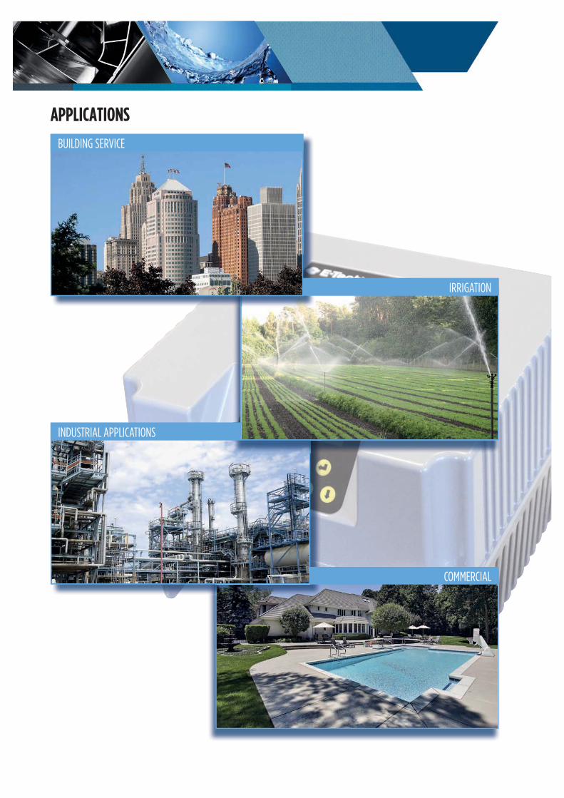
APPLICATIONS
BUILDING SERVICE
COMMERCIAL
IRRIGATION
INDUSTRIAL APPLICATIONS

DRIVE-TECH - A NEW GENERATION OF VFD
DRIVE-TECH
The new line of VFD DrivE-Tech has been designed and developed to optimize, control and protect pumping systems built with different kind of pumps like vertical multistage, centrifugal and submersible.
DrivE-Tech can work in applications like domestic, water supply, irrigation, commercial, HVAC, washing and more – it is suitable to operate in most of new or existing systems.
The installation of a DrivE-Tech allows the user to gain important benefits like:Reduced energy consumption with remarkable cost savingLonger life of pumping systemGreater reliability of the complete unit
DrivE-Tech controls are uniquely compact, and plugged with most of the pumps available in the market they can ensure steady operation conditions in terms of pressure, flow and temperature.
DrivE-Tech delivers motor protection and monitoring, such as:overload and dry running protectionintegrated soft start and soft stop functions, extending the life of the systemand reducing peak variationinput current and supply voltagerecording running hours and login errors and alarms reported by the systemcontrolling a second or third pump at constant speed DOL (DOL: Direct On Line)connecting to other DrivE-Tech to get combined operation
DrivE-Tech enclosure is entirely made of die-cast aluminum and is very sturdy, lightweight, easy to cool down and very compact in size.
Protection degree of the panel is IP55 thus it can be installed in humid and dusty places.
A display placed on top of DrivE-Tech and a buzzer in case of alarm help to operate the VFD in the most efficient and easy conditions.
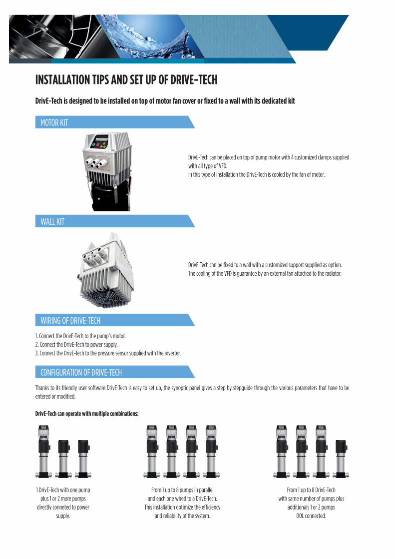
INSTALLATION TIPS AND SET UP OF DRIVE-TECH
DrivE-Tech is designed to be installed on top of motor fan cover or fixed to a wall with its dedicated kit
MOTOR KIT
WALL KIT
WIRING OF DRIVE-TECH
CONFIGURATION OF DRIVE-TECH
DrivE-Tech can be placed on top of pump motor with 4 customized clamps supplied with all type of VFD.In this type of installation the DrivE-Tech is cooled by the fan of motor.
DrivE-Tech can be fixed to a wall with a customized support supplied as option.The cooling of the VFD is guarantee by an external fan attached to the radiator.
1. Connect the DrivE-Tech to the pump’s motor.2. Connect the DrivE-Tech to power supply.3. Connect the DrivE-Tech to the pressure sensor supplied with the inverter.
From 1 up to 8 pumps in parallel and each one wired to a DrivE-Tech.
This installation optimize the efficiency and reliability of the system.
From 1 up to 8 DrivE-Tech with same number of pumps plus
additionals 1 or 2 pumps DOL connected.
1 DrivE-Tech with one pump plus 1 or 2 more pumps
directly conneted to power supply.
Thanks to its friendly user software DrivE-Tech is easy to set up, the synoptic panel gives a step by stepguide through the various parameters that have to be entered or modified.
DrivE-Tech can operate with multiple combinations:
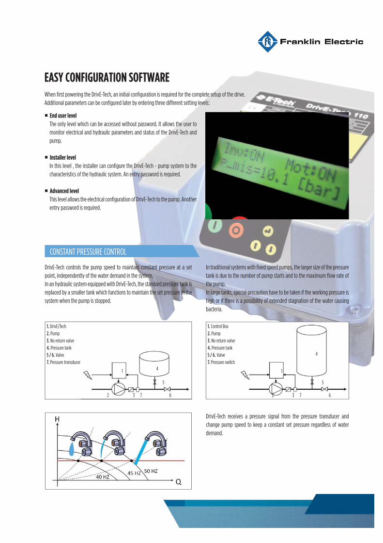
EASY CONFIGURATION SOFTWARE
CONSTANT PRESSURE CONTROL
When first powering the DrivE-Tech, an initial configuration is required for the complete setup of the drive.Additional parameters can be configured later by entering three different setting levels:
End user level
The only level which can be accessed without password. It allows the user tomonitor electrical and hydraulic parameters and status of the DrivE-Tech andpump.
Installer level
In this level , the installer can configure the DrivE-Tech - pump system to thecharacteristics of the hydraulic system. An entry password is required.
Advanced level This level allows the electrical configuration of DrivE-Tech to the pump. Another entry password is required.
DrivE-Tech controls the pump speed to maintain constant pressure at a set point, independently of the water demand in the system.In an hydraulic system equipped with DrivE-Tech, the standard pressure tank isreplaced by a smaller tank which functions to maintain the set pressure in the system when the pump is stopped.
1. DrivE/Tech2. Pump3. No return valve4. Pressure tank5 / 6. Valve7. Pressure transducer
1. Control Box2. Pump3. No return valve4. Pressure tank5 / 6. Valve7. Pressure switch
1 1
2 23 37 7
4
4
6 6
5 5
In traditional systems with fixed speed pumps, the larger size of the pressure tank is due to the number of pump starts and to the maximum flow rate of the pump.In large tanks, special precaution have to be taken if the working pressure is high or if there is a possibility of extended stagnation of the water causing bacteria.
DrivE-Tech receives a pressure signal from the pressure transducer and change pump speed to keep a constant set pressure regardless of water demand.

ELECTRONIC TAILORED FOR PUMPS
Minimum motor frequency
Stop function at zero water flow
Loss compensation proportional to the water flow
Settable carrier frequency between 2.5, 4, 8, 10, 12 kHz Several control modes available
Dry running signal via cos value V/f programmable curveMaximum and minimum pressure alarm
This parameter prevents the pump from running lower below a certain speed, avoiding the risk of damaging the thrust bearing in submersible pumps.Minimum motor frequency ramp
To prevent motor damage, the motor can accelerate quickly to reach the minimum motor frequency , and then is allowed to follow a lower start-up ramp.
After reaching the minimum frequency at zero flow (Fmin
Q=0) DrivE-Tech progressively slows the pump while monitoring the signal from the pressure transducer.If the pressure is close to the set pressure, DrivE-Tech stops the pump.
If the pressure sensor is placed near the pump, pressure value on the working point is lower than set pressure due to the loss proportional to the water flow.It is possible to vary the pressure set in a linear relation with respect to the frequency to compensate pressure loss in the pipes.
If pump runs dry, its cos value drops below a settable cos value and DrivE-Tech stops the pump after 2 seconds.DrivE-Tech will try to start the pump every 10, 20, 40, 80 and 160 minutes, after which it will declare an alarm and stop the pump if the condition persists.
If DrivE-Tech controls a submersible pump with long cables, it is possible to decrease the carrier frequency value to ensure longer motor life.
In addition to constant pressure control, DrivE-Tech allows other control modes such as fixed frequency, constant flow, constant temperature.
When the pressure rises above a certain settable pressure value, DrivE-Tech will stop the pump to prevent damages to the hydraulic components in the system.Similarly, if the pressure drops below a certain set pressure an alarms is declared and the pumpis stopped.
DrivE-Tech allows to choose between two different methods of torque control voltage versus pumps speed (frequency):
constant torque (linear V/f)quadratic variable torque (squared V/f)
For centrifugal pump, energy savings can beobtained by selecting squared V/f control.
181mm
227.5mm
181mm
180mm
260mm
260mm
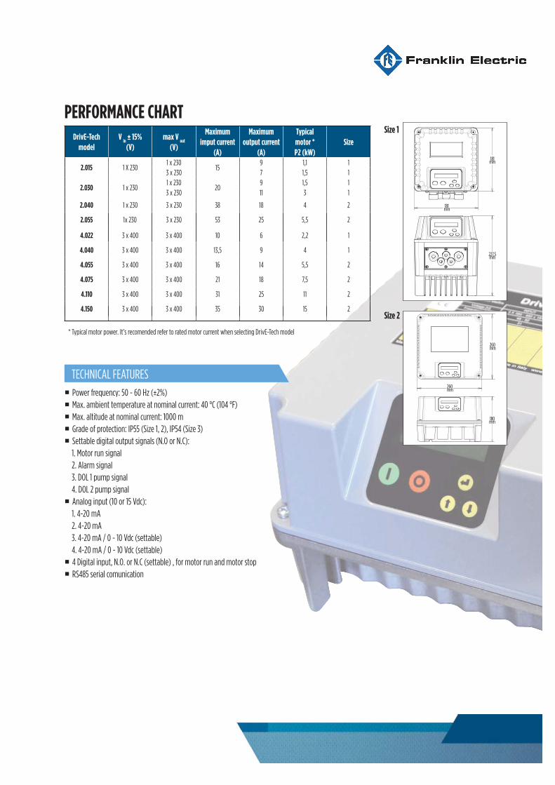
* Typical motor power. It’s recomended refer to rated motor current when selecting DrivE-Tech model
Power frequency: 50 - 60 Hz (±2%)Max. ambient temperature at nominal current: 40 °C (104 °F)Max. altitude at nominal current: 1000 mGrade of protection: IP55 (Size 1, 2), IP54 (Size 3)Settable digital output signals (N.O or N.C):1. Motor run signal2. Alarm signal3. DOL 1 pump signal4. DOL 2 pump signalAnalog input (10 or 15 Vdc):1. 4-20 mA2. 4-20 mA3. 4-20 mA / 0 - 10 Vdc (settable)4. 4-20 mA / 0 - 10 Vdc (settable)4 Digital input, N.O. or N.C (settable) , for motor run and motor stopRS485 serial comunication
PERFORMANCE CHART
DrivE-Tech
model
V in
± 15%
(V)
max V out
(V)
Maximum
imput current
(A)
Maximum
output current
(A)
Typical
motor *
P2 (kW)
Size
2.015 1 X 2301 x 230
159 1,1 1
3 x 230 7 1,5 1
2.030 1 x 2301 x 230
209 1,5 1
3 x 230 11 3 1
2.040 1 x 230 3 x 230 38 18 4 2
2.055 x 230 3 x 230 53 25 5,5 2
4.022 3 x 400 3 x 400 10 6 2,2 1
4.040 3 x 400 3 x 400 13,5 9 4 1
4.055 3 x 400 3 x 400 16 14 5,5 2
4.075 3 x 400 3 x 400 21 18 7,5 2
4.110 3 x 400 3 x 400 31 25 11 2
4.150 3 x 400 3 x 400 35 30 15 2
TECHNICAL FEATURES
Size 1
Size 2
FE1182_ 05/2018
Franklin Electric (Australia) Pty. Ltd.106-110 Micro Circuit, Dandenong South, (Victoria) Australia
Phone. +61 3 9799 5000 - Fax. +61 3 9799 5050Contacts: [email protected]
Franklin Electric S.r.l. Via Asolo, 7 - 36031 Dueville (Vicenza) Italy
Single member - Company subject to the control and coordination of Franklin Electric Co., Inc.
NOTE: Franklin Electric s.r.l. reserves the right to amend specification without prior notice