vehicle in the loop - mathworks€¢ realistic “real time” vehicle dynamics model why “vehicle...
TRANSCRIPT

Vehicle in the Loop
An integrated approach for Chassis Systems development
November, 4th 2014
E. Raffone, C. Rei, M. Ieluzzi, P.P. Paravizzini, P. Turco
CHASSIS & Vehicle Dynamics
Vehicle in the Loop:
an integrated approach for Chassis Systems development
This document contains information which are proprietary of CRF. Neither this document nor the information contained herein shall be used, duplicated nor communicated by any means to any third party, in whole or in part, except with the prior written consent of CRF
4-11-2014
Public
Agenda
2
� System set-up for ABS/ESC application
o Software Architecture (RapidPro ECU sw)
o Open loop testing functionality
o Basic 3D environment
� Model Based Development Process: Main Design & Validation step
o Vehicle Dynamics Modelling
o Software in the Loop - Example of “fault injection”
o Vehicle Experimental Development & Performances Validation
� Vehicle in the Loop concept idea
� VIL - System Architecture & Preliminary Realization
� CRF’s V.I.L. Laboratory
� Conclusion & Next Steps

Vehicle in the Loop:
an integrated approach for Chassis Systems development
This document contains information which are proprietary of CRF. Neither this document nor the information contained herein shall be used, duplicated nor communicated by any means to any third party, in whole or in part, except with the prior written consent of CRF
4-11-2014
Public
Model-Based Development Process
Integration of different experiences & skills
3
System ValidationSystem DesignReq. & Constrains
System Control Design
CIL (Component In the Loop)
HIL (Hardware In the Loop)
Safety assessment
(eg. Fault injection)
System Calibration &
Perform. Assessment
On Vehicle System
Validation & Develop.
Safety
Requirements
(PHA,FMEA,..)
Performance Requirements
(eg.Target Setting)
Constraints
(Cost, Power,...)
Functional Requirements
Design Flow
“Rapid Prototyping” Code generation
Target ECU
Code Generation
(fixed point, ..
(Software In
the Loop)
IO-62-DV
IO-63-DV
Bench Test
Validation & Develop.
2008-10B-IO-001
2008-10B-IO-001
Architecture & System Design
Modeling & Identification
IO-60-DV
IO-61-DV
Diagnosis DesignRevision phase
SIL
Recovery Design
Vehicle Dynamics
Virtual Analysis
Chassis Systems
V.D. Performances
Development & Evaluation

Vehicle in the Loop:
an integrated approach for Chassis Systems development
This document contains information which are proprietary of CRF. Neither this document nor the information contained herein shall be used, duplicated nor communicated by any means to any third party, in whole or in part, except with the prior written consent of CRF
4-11-2014
Public
Model Based Development
Main Design & Validation step
4
Hardware in the Loop • Real Hardware;
• Real-time Vehicle Model
Vehicle Development & ValidationObjective & Subjective “on Track” Assessment
Revision phase
Revision phase
Vehicle model
Active systems model
Systems ValidationSystems Design
Revision phase Vehicle simulator
COMPONENTE DA TESTARE
Attuatore
Emulazione Sensori
Output simulatore
Seganli di misura Comandi
Input simulatore
Software Real-Time
SensoriHDW to SFW
AttuazioneHARDWARE
SOFTWARE DI
SIMULAZIONE
Software in the Loop• System Hardware Model;
• Vehicle Model.
H2IL
BBW_System Simulink Model
Vehicle Simulink Model
Libreria CAE diSistemi Controllo Autotelaio
From WorkSpace:
• Simulazione manovre;
• Simulazioni Fault;
To WorkSpace:
• Risultati;

Vehicle in the Loop:
an integrated approach for Chassis Systems development
This document contains information which are proprietary of CRF. Neither this document nor the information contained herein shall be used, duplicated nor communicated by any means to any third party, in whole or in part, except with the prior written consent of CRF
4-11-2014
Public
Model Based Development
Vehicle Dynamics Modelling
-40 -30 -20 -10 0 10 20 30 400
100
200
300
400
500
600
Angolo ruote (δruote) [deg]
Angolo
vola
nte
( δ
vol)
[deg]
Tau = 13
sx
dx
-40 -30 -20 -10 0 10 20 30 400
100
200
300
400
500
600
Angolo ruote (δruote) [deg]
Angolo
vola
nte
( δ
vol)
[deg]
Tau = 13
sx
dx
-100 -50 0 50 100-2
-1.5
-1
-0.5
0
0.5
1
1.5
2
-360
-90-4504590
360
Scuotimento ∆x [mm]
∆ ε
= f
( ∆x, δ
ruote
) [d
eg]
TAMPONAMENTO RIMBALZO
-100 -50 0 50 100-2
-1.5
-1
-0.5
0
0.5
1
1.5
2
-360
-90-4504590
360
Scuotimento ∆x [mm]
∆ ε
= f
( ∆x, δ
ruote
) [d
eg]
TAMPONAMENTO RIMBALZO
Suspension & Steer elastic & kinematics
characteristics
Vehicle Inertial & geometric properties
Vehicle Models
0 10 20 300
2000
4000
6000
scorrimento [%]
Fx [
N]
Fz = 1 KN
Pneumatici Posteriori = Mich_ENXH1_185_65_15
Fz = 2 KN
Fz = 3 KN
Fz = 4 KN
Fz = 5 KN
0 5 10 150
2000
4000
6000
deriva [deg]
Fy [
N]
Fz = 1 KN
Fz = 2 KN
Fz = 3 KN
Fz = 4 KN
Fz = 5 KN
0 5 10 15-100
-50
0
50
deriva [deg]
Mz [
Nm
]
Fz = 1 KNFz = 2 KN
Fz = 3 KN
Fz = 4 KN
Fz = 5 KN0 50 100
0
50
100
mux [%]
mu
y [
%]
alfa = 2°
Fz = 4 KN
alfa = 4°
Fz = 4 KN
alfa = 6°
Fz = 4 KNalfa = 8°
Fz = 4 KN
Tyre characteristics
From detailed data (multi-body model) . . .
. . . to functional “real time” model
5

Vehicle in the Loop:
an integrated approach for Chassis Systems development
This document contains information which are proprietary of CRF. Neither this document nor the information contained herein shall be used, duplicated nor communicated by any means to any third party, in whole or in part, except with the prior written consent of CRF
4-11-2014
Public
Model Based Development
Software in the Loop - Example of “fault injection”
45 degree Step steer input @ 100 kph
No faultNO Diagnosis
Diagnostic
Isolation
Fault: primary Steer sensor � 0°
Effect = Yaw Disturbances
Fault
Steering Wheel angle fault
Steer by WireECU Model &
Control Strategy
Actuator Model Sensors modelVehicle Model
6

Vehicle in the Loop:
an integrated approach for Chassis Systems development
This document contains information which are proprietary of CRF. Neither this document nor the information contained herein shall be used, duplicated nor communicated by any means to any third party, in whole or in part, except with the prior written consent of CRF
4-11-2014
Public
Model Based Development
Vehicle Experimental Development & Performances Validation
Vehicle “tuning”
Test plan definition
& vehicle setup
1 2 3 4 5 6 7 8 9 10Hz
Vehicle A
Vehicle B
Vehicle C
Experimental data analysis
Objective & Subjective Assessment
Revision phase
Output for the
7

Vehicle in the Loop:
an integrated approach for Chassis Systems development
This document contains information which are proprietary of CRF. Neither this document nor the information contained herein shall be used, duplicated nor communicated by any means to any third party, in whole or in part, except with the prior written consent of CRF
4-11-2014
Public
Model Based Development
Main Design & Validation step
8
Hardware in the Loop • Real Hardware;
• Real-time Vehicle Model
Vehicle Development & ValidationObjective & Subjective “on Track” Assessment
Revision phase
Revision phase
Vehicle model
Active systems model
Systems ValidationSystems Design
Revision phase Vehicle simulator
COMPONENTE DA TESTARE
Attuatore
Emulazione Sensori
Output simulatore
Seganli di misura Comandi
Input simulatore
Software Real-Time
SensoriHDW to SFW
AttuazioneHARDWARE
SOFTWARE DI
SIMULAZIONE
Software in the Loop• System Hardware Model;
• Vehicle Model.
H2IL
Vehicle in the Loop
BBW_System Simulink Model
Vehicle Simulink Model
Libreria CAE diSistemi Controllo Autotelaio
From WorkSpace:
• Simulazione manovre;
• Simulazioni Fault;
To WorkSpace:
• Risultati;

Vehicle in the Loop:
an integrated approach for Chassis Systems development
This document contains information which are proprietary of CRF. Neither this document nor the information contained herein shall be used, duplicated nor communicated by any means to any third party, in whole or in part, except with the prior written consent of CRF
4-11-2014
Public
Vehicle in the Loop concept idea
RT model & Bench control
BenchElectronics
Visualization & Data acq.
Workshop car lifter
Pc projector
• Simple and robust HIL for in workshop usage
• Complete active system HW & E/E architecture
• Standard interface for Human interaction
• Realistic “Real Time” Vehicle Dynamics Model
Why “Vehicle in the Loop” ?
� It’s based on the same commercial tools normally used by car engineer
� We built cars & ViL approach is the development tool closer to the real cars
� It’s a simple way to apply HIL techniques in day-by-day workshop usage
� It’s a portable system. Simple to be used close to the test track
9

Vehicle in the Loop:
an integrated approach for Chassis Systems development
This document contains information which are proprietary of CRF. Neither this document nor the information contained herein shall be used, duplicated nor communicated by any means to any third party, in whole or in part, except with the prior written consent of CRF
4-11-2014
Public
Vehicle in the Loop
System Architecture & Preliminary Realization
Real-Time
Vehicle
Model
Visualization
&
Data Acq.
Chassis
Systems
& HMI
Analog & Digital SignalsEmulated Measurements
& Expected CAN Signals
Auxiliary
CAN Network
1st Preliminary Realization
Steering
Sensor
Master
Cylinder
Pressure
Gas Pedal
Position
Brake
Switch
Clutch
Switch
…e.g.
Gyro
Engine
Signals
Wheel
Sensors
…
Visualization
PC Gas Pedal
Brake Pedal
Real-Time
Vehicle Model
Steering
CAR Visualization
10
Vehicle in the Loop:
an integrated approach for Chassis Systems development
This document contains information which are proprietary of CRF. Neither this document nor the information contained herein shall be used, duplicated nor communicated by any means to any third party, in whole or in part, except with the prior written consent of CRF
4-11-2014
Public
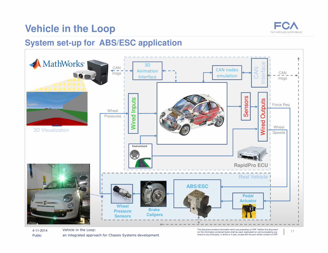
Vehicle in the Loop
System set-up for ABS/ESC application
Sensors
ABS/ESC
PedalActuator
Wired Inputs
Wired O
utp
uts
CAN nodes
emulation CA
N
Inte
rface
Real Vehicle
Force Req
Wheel
Speeds
Wheel
Pressures
CAN
msgs
3D
Animation
Interface
RapidPro ECU
CAN
msgs
3D Visualization
Wheel PressureSensors
Brake Calipers
11
Vehicle in the Loop:
an integrated approach for Chassis Systems development
This document contains information which are proprietary of CRF. Neither this document nor the information contained herein shall be used, duplicated nor communicated by any means to any third party, in whole or in part, except with the prior written consent of CRF
4-11-2014
Public
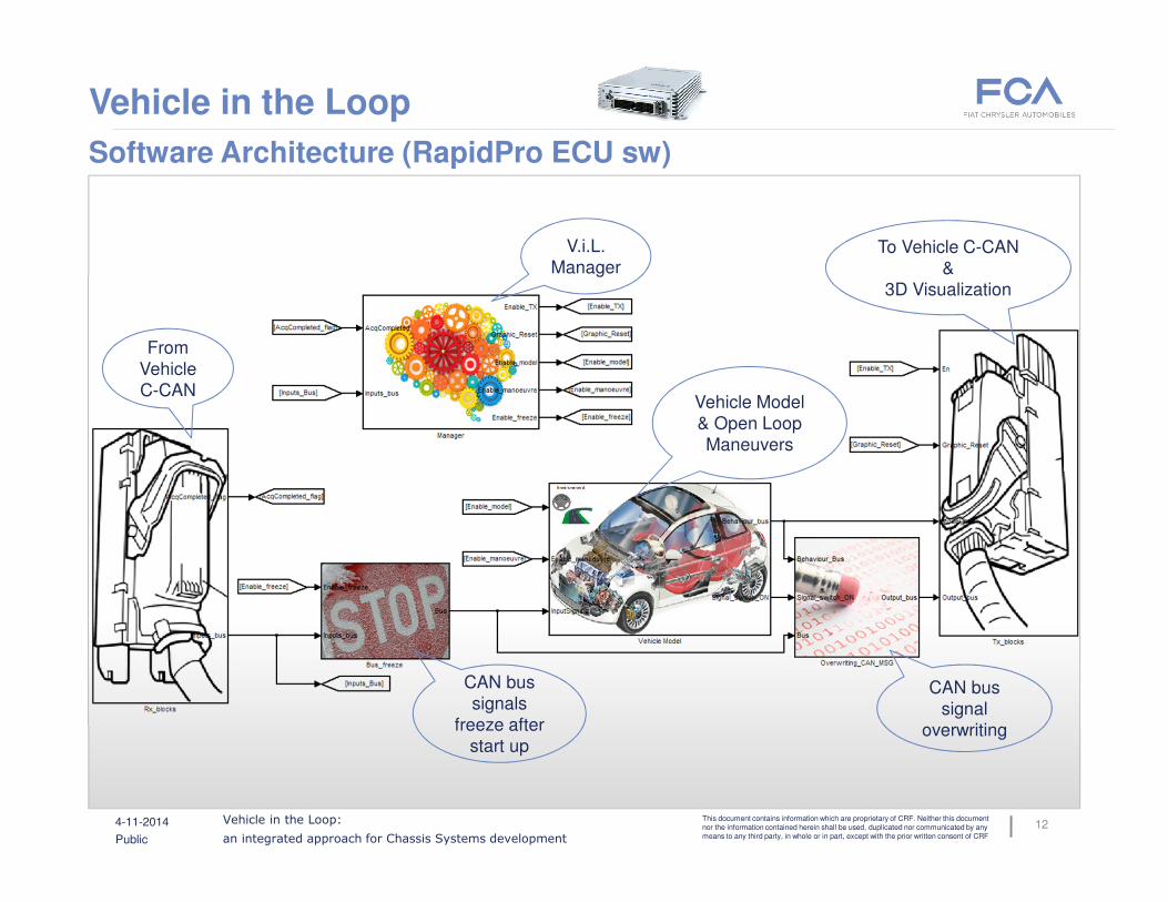
Vehicle in the Loop
Software Architecture (RapidPro ECU sw)
V.i.L.
Manager
CAN bus
signal
overwriting
CAN bus
signals
freeze after
start up
Vehicle Model
& Open Loop
Maneuvers
From
Vehicle
C-CAN
To Vehicle C-CAN
&
3D Visualization
12

Vehicle in the Loop:
an integrated approach for Chassis Systems development
This document contains information which are proprietary of CRF. Neither this document nor the information contained herein shall be used, duplicated nor communicated by any means to any third party, in whole or in part, except with the prior written consent of CRF
4-11-2014
Public
Vehicle in the Loop
Open loop testing functionalities
M
e
r
g
e
Emulated input
Applied
input
0 2 4 6 8 100
20
40
60
80
100
120
140
160
180Steering-wheel angle
time [s]
[deg]
0 1 2 3 4 5 6 70
10
20
30
40
50
60
70
80
90Steering-wheel angle
time [s]
[deg]
0 5 10 15 20 25 30-40
-30
-20
-10
0
10
20
30
40Steering-wheel angle
time [s]
[deg
]
Open-loop commands profile
Maneuvers manager
Robot driver
13

Vehicle in the Loop:
an integrated approach for Chassis Systems development
This document contains information which are proprietary of CRF. Neither this document nor the information contained herein shall be used, duplicated nor communicated by any means to any third party, in whole or in part, except with the prior written consent of CRF
4-11-2014
Public
Vehicle in the Loop
Open loop testing results – emulated input
0 1 2 3 4 5 6 7-4
-2
0
2
4
6
8
10
Tempo [s]
[m/s
2],
[deg]
& [
km
/h]
Vel*Psip
Ay
Beta
Dfmedio
Vel/10
0 1 2 3 4 5 6 70
50
100
[deg]
Steering wheel angle
0 1 2 3 4 5 6 70
20
40
60Gas Pedal
time [s]
[%]
0 1 2 3 4 5 6 70
50
100
[deg]
Steering wheel angle
0 1 2 3 4 5 6 70
20
40
60Gas Pedal
time [s]
[%]
Steer step manoeuvre
14

Vehicle in the Loop:
an integrated approach for Chassis Systems development
This document contains information which are proprietary of CRF. Neither this document nor the information contained herein shall be used, duplicated nor communicated by any means to any third party, in whole or in part, except with the prior written consent of CRF
4-11-2014
Public
Vehicle in the Loop
Basic 3D environment based on MathWorks Toolboxes
Visualization
&
Data Acq.
From Vehicle
Model
Visualization
Sink
15

Vehicle in the Loop:
an integrated approach for Chassis Systems development
This document contains information which are proprietary of CRF. Neither this document nor the information contained herein shall be used, duplicated nor communicated by any means to any third party, in whole or in part, except with the prior written consent of CRF
4-11-2014
Public
Vehicle in the Loop
CRF’s V.I.L. Laboratory
16

Vehicle in the Loop:
an integrated approach for Chassis Systems development
This document contains information which are proprietary of CRF. Neither this document nor the information contained herein shall be used, duplicated nor communicated by any means to any third party, in whole or in part, except with the prior written consent of CRF
4-11-2014
Public
Vehicle in the Loop
ABS in action on Vehicle in low µ
0 5 10 15 20 250
50
100
150
200
Time [sec]
Pre
ssu
re [b
ar]
Master Cylinder Pressure
0 5 10 15 20 25-50
0
50
100
150
Fro
nt
Wh
ee
l P
res
su
re [
ba
r]
0 5 10 15 20 250
50
100
150
Re
ar
Wh
ee
l Pre
ss
ure
[b
ar]
Time [s]
sx
dx
0 5 10 15 20 25-50
0
50
100
150
Wh
ee
l Sp
ee
d [K
m/h
]
Time [s]
Front Left Wheel
VG
Wheel
0 5 10 15 20 25-50
0
50
100
150
Wh
ee
l Sp
ee
d [K
m/h
]
Time [s]
Front Right Wheel
VG
Wheel
0 5 10 15 20 25-50
0
50
100
150
Wh
ee
l Sp
ee
d [K
m/h
]
Time [s]
Rear Left Wheel
VG
Wheel
0 5 10 15 20 25-50
0
50
100
150
Wh
ee
l Sp
ee
d [K
m/h
]
Time [s]
Rear Right Wheel
VG
Wheel
Wheel Pressure Sensors
Brake Calipers
Brake action
Master Cylinder Pressure Sensors
Wheel Speed Signals
ABS/ESC
17
Vehicle in the Loop:
an integrated approach for Chassis Systems development
This document contains information which are proprietary of CRF. Neither this document nor the information contained herein shall be used, duplicated nor communicated by any means to any third party, in whole or in part, except with the prior written consent of CRF
4-11-2014
Public
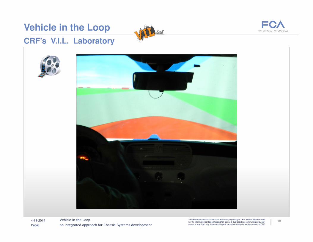
Vehicle in the Loop
CRF’s V.I.L. Laboratory
18

Vehicle in the Loop:
an integrated approach for Chassis Systems development
This document contains information which are proprietary of CRF. Neither this document nor the information contained herein shall be used, duplicated nor communicated by any means to any third party, in whole or in part, except with the prior written consent of CRF
4-11-2014
Public
Conclusion & Next Steps
Next Steps
� VIL approach extension to all Chassis Systems
� Automation of “Robot driver” / Emulated input testing
� VIL system integration with CRF’s Virtual Reality Lab
Conclusion
� A new approach to support Chassis System development has been shown
� VIL approach is a flexible, cheap and close to the real cars
� VIL is portable and robust. Simple to be moved closer to vehicle testing area
� VIL is based on the same commercial tools normally used by car engineer
� MATLAB/Simulink toolboxes cover the main part of VIL approach needs
� 1st test case applied to ABS/ESC system has showed big potentiality
19

Vehicle in the Loop:
an integrated approach for Chassis Systems development
This document contains information which are proprietary of CRF. Neither this document nor the information contained herein shall be used, duplicated nor communicated by any means to any third party, in whole or in part, except with the prior written consent of CRF
4-11-2014
Public
Thanks for your kind attention
P. Turco - CHASSIS & Vehicle Dynamics
Tel.: +39 011 9083.826 E-mail: [email protected]
Enrico RAFFONE
Michele IELUZZI Claudio REI
Pier Paolo PARAVIZZINI
20