verification of safety properties for relay interlocking...
TRANSCRIPT

Verification of Safety Properties forRelay Interlocking Systems
Louise Elmose Eriksen and Boe Pedersen
Kongens Lyngby 2010IMM-M.Sc.-2010-57

Technical University of DenmarkInformatics and Mathematical ModellingBuilding 321, DK-2800 Kongens Lyngby, DenmarkPhone +45 45253351, Fax +45 [email protected]
IMM-M.Sc.: ISSN 0909-3192

Summary
Many people travel by train, and thus rely on trains being a safe means oftransportation. BaneDanmark, who is responsible for most of the Danish railwaynetwork, uses relay based interlocking systems to ensure that no trains collideand no trains derail.
The goal of this project is to develop a method for deriving safety propertiesfrom a given relay interlocking system and for specifying how the interlockingsystem can be verified in relation to the safety properties.
In order to derive and formalise safety properties it has been decided that amodel of relay interlocking systems should be developed. The model has beenspecified in the formal specification language Maude which additionally can beused for model verification as it provides a model checking tool. LTL (LinearTemporal Logic) is used to formalise the safety properties, thus enabling thatthe safety properties can be verified using the Maude model checking tool.
The behaviour of interlocking systems as well as the methods for deriving safetyproperties from a model and verifying a given model in relation to these safetyproperties, has been specified in a generic way, to support any given interlockingsystem. Additionally, some tools have been developed to ease the specificationof a model given the documentation of an interlocking system.
The method has been successfully applied to a number of smaller interlockingsystems and partly to the more complex system of Stenstrup station.

ii

Resume
Mange mennesker rejser med tog og forventer at dette er en sikker made at blivetransporteret pa. BaneDanmark, som er ansvarlig for de danske jernbaner,bruger relæsikringsanlæg til at sikre, at der hverken kan forekomme togkolli-sioner eller togafkørsler.
Malet med dette projekt er, at udvikle en metode til at udlede sikkerhed-segenskaber ud fra et givent relæsikringsanlæg og til at specificere, hvordanet sikringsanlæg kan verificeres i forhold til disse sikkerhedsegenskaber.
For at kunne udlede og formalisere sikkerhedsegenskaber, har vi valgt, at derskal udvikles en model for relæsikringsanlæg. Denne model er specificeret i detformelle specifikationssprog Maude som yderligere kan bruges til at verificeremodellen, da Maude har et værktøj til at model checke. LTL (Linear TemporalLogic) er brugt til at formalisere sikkerhedsegenskaberne, og derved gøres detmuligt, at sikkerhedsegenskaberne kan verificeres ved brug af Maude’s modelchecker værktøj.
Savel sikringsanlægs opførserl som metoder til at udlede sikkerhedsegenskaberfra en model og til at verificere en given model i forhold til disse udledte sikker-hedsegenskaber, er blevet specificeret pa generisk vis, sa det kan anvendes paet hvilket som helst sikringsanlæg. Ydermere er der blevet udviklet en rækkeværktøjer, der givet dokumentationen for et sikringsanlæg, simplificerer speci-fikationen af en model.
Denne metode er med succes blevet anvendt pa en række mindre sikringsanlægog pa delvist Stenstrup stations mere komplekse system.

iv

Preface
This master thesis was prepared at the Department of Informatics and Math-ematical Modelling, the Technical University of Denmark in fulfilment of therequirements for acquiring the MSc degree in Computer Science and Engineer-ing.
The objective is to use formal methods to model and verify a part of the Danishrailway network based on documentation from BaneDanmark.
The thesis supervisor is Associate Professor Anne E. Haxthausen, Departmentof Informatics and Mathematical Modelling, Technical University of Denmark.
Lyngby, August 2010
Louise Elmose Eriksen (s042150) Boe Pedersen (s042229)

vi

Acknowledgements
We would like to thank our supervisor Anne Haxthausen for her inspirationalenthusiasm and her valuable advice and ideas.
We would also like to express our gratitude to Kokichi Futatsugi for inviting usto the JAIST advanced school on formal specification and systems verification.Furthermore we want to thank all the lecturers on the advanced school, espe-cially Kokichi Futatsugi and Jose Meseguer, for providing insight in CafeOBJand Maude.
Finally, we would like to thank Francisco Duran for assisting us with Maudespecific issues.

viii

Contents
Summary i
Resume iii
Preface v
Acknowledgements vii
1 Introduction 1
1.1 Motivation . . . . . . . . . . . . . . . . . . . . . . . . . . . . . . 1
1.2 Goal and Method . . . . . . . . . . . . . . . . . . . . . . . . . . . 2
1.3 Chapter Overview . . . . . . . . . . . . . . . . . . . . . . . . . . 3
1.4 Reader Assumptions . . . . . . . . . . . . . . . . . . . . . . . . . 4
2 Domain 5
2.1 Creating an Interlocking System . . . . . . . . . . . . . . . . . . 6
2.2 Track Layout . . . . . . . . . . . . . . . . . . . . . . . . . . . . . 7
2.3 Train Route Table . . . . . . . . . . . . . . . . . . . . . . . . . . 9
2.4 Circuit . . . . . . . . . . . . . . . . . . . . . . . . . . . . . . . . . 15
2.5 Trains . . . . . . . . . . . . . . . . . . . . . . . . . . . . . . . . . 23
2.6 Normal State of an Interlocking System . . . . . . . . . . . . . . 23
2.7 Using an Interlocking System . . . . . . . . . . . . . . . . . . . . 24
3 Modelling Language 27
3.1 Considered Specification Languages . . . . . . . . . . . . . . . . . 28
3.2 What is Maude . . . . . . . . . . . . . . . . . . . . . . . . . . . . 30
3.3 Introduction to Maude . . . . . . . . . . . . . . . . . . . . . . . . 34
x CONTENTS
4 Method Overview 574.1 Specifying the Model . . . . . . . . . . . . . . . . . . . . . . . . . 594.2 Deriving Safety Properties . . . . . . . . . . . . . . . . . . . . . . 604.3 Verification . . . . . . . . . . . . . . . . . . . . . . . . . . . . . . 60
5 Specifying the Model 615.1 Scope and Assumptions . . . . . . . . . . . . . . . . . . . . . . . 625.2 Modelling Components . . . . . . . . . . . . . . . . . . . . . . . . 645.3 Modelling Current . . . . . . . . . . . . . . . . . . . . . . . . . . 825.4 Modelling a Kripke Structure of an Interlocking System . . . . . 855.5 Modelling Behaviour . . . . . . . . . . . . . . . . . . . . . . . . . 945.6 Conditions for a Sound Result . . . . . . . . . . . . . . . . . . . . 1125.7 Size of the Kripke Structure . . . . . . . . . . . . . . . . . . . . . 1195.8 Performance . . . . . . . . . . . . . . . . . . . . . . . . . . . . . . 130
6 Deriving Safety Properties 1356.1 Train Route Table Safety Properties . . . . . . . . . . . . . . . . 1366.2 General Safety Properties . . . . . . . . . . . . . . . . . . . . . . 145
7 Verification 1497.1 Initial State . . . . . . . . . . . . . . . . . . . . . . . . . . . . . . 1507.2 Test . . . . . . . . . . . . . . . . . . . . . . . . . . . . . . . . . . 1517.3 Well-Formedness . . . . . . . . . . . . . . . . . . . . . . . . . . . 1537.4 Confidence Conditions . . . . . . . . . . . . . . . . . . . . . . . . 1547.5 Safety Properties . . . . . . . . . . . . . . . . . . . . . . . . . . . 1557.6 Results . . . . . . . . . . . . . . . . . . . . . . . . . . . . . . . . . 156
8 Auxilliary Tools 1698.1 Extended Simulator . . . . . . . . . . . . . . . . . . . . . . . . . 1698.2 Tester . . . . . . . . . . . . . . . . . . . . . . . . . . . . . . . . . 170
9 Related Work 1719.1 Simulation of Relay Interlocking Systems . . . . . . . . . . . . . 1719.2 Modelling Interlocking Systems for Railway Stations . . . . . . . 1729.3 Verification of Safety Properties for Relay Interlocking Systems . 173
10 Future Work 179
11 Conclusion 181
A Terms 183
B How to use Maude 187B.1 Installing Maude on Unix . . . . . . . . . . . . . . . . . . . . . . 187B.2 Interacting with Maude . . . . . . . . . . . . . . . . . . . . . . . 188

CONTENTS xi
C Module structure 189
D Maude Built-In Modules 191D.1 CONFIGURATION . . . . . . . . . . . . . . . . . . . . . . . . . 191D.2 QID . . . . . . . . . . . . . . . . . . . . . . . . . . . . . . . . . . 192D.3 NAT . . . . . . . . . . . . . . . . . . . . . . . . . . . . . . . . . . 192D.4 BOOL . . . . . . . . . . . . . . . . . . . . . . . . . . . . . . . . . 194D.5 EXT-BOOL . . . . . . . . . . . . . . . . . . . . . . . . . . . . . . 195D.6 MODEL-CHECKER . . . . . . . . . . . . . . . . . . . . . . . . . 195D.7 LTL . . . . . . . . . . . . . . . . . . . . . . . . . . . . . . . . . . 196D.8 LTL-SIMPLIFIER . . . . . . . . . . . . . . . . . . . . . . . . . . 198D.9 SATISFACTION . . . . . . . . . . . . . . . . . . . . . . . . . . . 200
E Model and Verification Maude Modules 201E.1 Model . . . . . . . . . . . . . . . . . . . . . . . . . . . . . . . . . 201E.2 Verification Modules . . . . . . . . . . . . . . . . . . . . . . . . . 224
F Maude Example Modules 247F.1 PERSON3 . . . . . . . . . . . . . . . . . . . . . . . . . . . . . . . 247F.2 PERSON3-QID . . . . . . . . . . . . . . . . . . . . . . . . . . . . 249F.3 PERSON3-SAT . . . . . . . . . . . . . . . . . . . . . . . . . . . . 250
G Point Solution 253
H Test 259H.1 Creating and Running New Tests . . . . . . . . . . . . . . . . . . 259H.2 Running Existing Tests . . . . . . . . . . . . . . . . . . . . . . . 262H.3 Functional Tests . . . . . . . . . . . . . . . . . . . . . . . . . . . 262
I CD Content 287I.1 /auxilliaryTools . . . . . . . . . . . . . . . . . . . . . . . . . . . . 287I.2 /maudeModules . . . . . . . . . . . . . . . . . . . . . . . . . . . . 287I.3 /report . . . . . . . . . . . . . . . . . . . . . . . . . . . . . . . . 288I.4 /stenstrup . . . . . . . . . . . . . . . . . . . . . . . . . . . . . . . 288I.5 /test . . . . . . . . . . . . . . . . . . . . . . . . . . . . . . . . . . 288I.6 /verification . . . . . . . . . . . . . . . . . . . . . . . . . . . . . . 289
J Designing and Verifying an Interlocking System 291J.1 Designing an Interlocking System . . . . . . . . . . . . . . . . . . 291J.2 Verifying an Interlocking System . . . . . . . . . . . . . . . . . . 292
K Manuals for Auxiliary Tools 293K.1 Extended Simulator . . . . . . . . . . . . . . . . . . . . . . . . . 293K.2 Tester . . . . . . . . . . . . . . . . . . . . . . . . . . . . . . . . . 296

xii CONTENTS
Bibliography 299

Chapter 1
Introduction
1.1 Motivation
Railway systems are highly safety-critical systems which means a failure of oper-ation could result in deaths or serious injuries. Various kinds of railway systemscan be used to control signals, points etc. to make railway traffic safe by ensuringthat no collisions nor derailings can happen.
The railway systems that are mainly used in Denmark are relay interlockingsystems. BaneDanmark, who is responsible for most of the Danish railway net-work, has not formally proved or verified whether the relay interlocking systemsare safe meaning neither collisions nor derailings can happen.
BaneDanmark documents relay interlocking systems on paper. Currently, theonly way to verify that relay interlocking systems behave as expected is to manu-ally analyse this documentation. As relay interlocking systems are very complexeven for simple stations with few platforms, a manual verification process wouldbe very difficult and cumbersome.

2 Introduction
1.2 Goal and Method
The goal of this project is to develop a method for deriving safety propertiesfrom a given relay interlocking system and for specifying how the interlockingsystem can be verified in relation to the safety properties.
The main approach can be seen in figure 1.1. Given the documentation of a
Figure 1.1: The main approach to achieve the goal of this project is to find methods to1) translate the documentation of a given station to a model in a specification language,2) derive safety properties from the model and 3) verify whether the model satisfies thederived safety properties.
relay interlocking system, it should somehow be possible to specify a model ofthis system using a specification language. Having such a model, the safetyproperties related to the associated interlocking system should be genericallyderived from the model. Finally, a generic method for how to verify whether agiven model satisfies the derived safety properties should be developed.
The safety properties can be split up in to two categories:
1. General safety properties. These safety properties apply to all railwaysystems and define that collisions and derailings must never take place.
2. Train route table safety properties. These safety properties are related torelay interlocking systems. The interlocking systems use certain means toensure safety on stations by introducing the concept of train routes, whichare used to ensure that the system behaves as expected. These propertiesare also called derived safety properties.
However, if the methods are successfully applied and a model of a relay inter-locking system is verified to satisfy the train route table safety properties one canonly conclude that the relay interlocking system behaves as expected in relationto the documentation. If the verification succeeds and some unsafe situations

1.3 Chapter Overview 3
have been overlooked when designing the system, these are not identified byonly verifying the train route table safety properties. For this reason it makessense to also formalise the general safety properties and describe how these canbe verified.
If the verification of the derived safety properties succeeds and the verificationof the general safety properties fails, one can conclude that either the documen-tation of the relay interlocking system is erroneous, or that relay interlockingsystems in general do not ensure safety.
In order to be able to verify that a model of a given interlocking system satisfiesa number of properties a suitable modelling language as well as a verificationmethod must be chosen. When a modelling language has been chosen, a modelof an interlocking system must be constructed. After this it must be decidedhow to derive the safety properties from the documentation and finally a methodfor verifying the model must be developed.
1.3 Chapter Overview
Chapter 2 describes the domain of this project, i.e. the domain of relay inter-locking systems. Extensive documentation of the domain already exists in[5, 1] and for this reason the chapter will be limited to describe only theareas of the domain that are strictly necessary in order to understand thework and considerations of this project.
Chapter 3 discusses modelling languages that have been considered for mod-elling and verifying the domain, and gives an introduction to the chosenlanguage.
Chapter 4 provides an overview of the method used for modelling and verifyingan interlocking system.
Chapter 5 explains how a model of an interlocking system has been specified.
Chapter 6 defines how safety properties can be derived from the requirementsspecification of the domain as well as how they and the general safetyproperties (no collision and no derailing) will be specified.
Chapter 7 describes how a model of an interlocking system can be verified inrelation to the derived safety properties and the general safety properties.
Chapter 8 lists the auxiliary tools that have been created during this project inorder to ease the process of developing a model of an interlocking system.

4 Introduction
Chapter 9 gives an overview of the previous work done in the domain of relayinterlocking systems and points out what exactly this project contributeswith.
Chapter 10 lists a number of suggestions for how the work done during thisproject can be continued in order to improve the results.
Chapter 11 summarises the work done during this project and presents theconclusions.
Appendices A to K contains among other things the code and tests of themodel, an overview of the content of the CD handed in with the reportand manuals for how to use the developed tools.
1.4 Reader Assumptions
It is assumed that the reader of this report has basic knowledge of the followingareas:
� A specification language, e.g. the Raise Specification Language (RSL) [25].
� State diagrams
� Temporal logic
� Model checking
� Basic data structures, e.g. sets, lists and graphs.

Chapter 2
Domain
In this section the project domain i.e. a subset of the Danish railway network,will be explained. As there already exists detailed documentation of the domainin [5, 1], only the parts that are strictly necessary for understanding the consid-erations of modelling and verifying an interlocking system are explained in thissection. Due to the thorough documentation that already exists some parts ofthis section will overlap with [5, 1], but the reason for including the material isto make the report independent of previous work.
There are many different types of railway systems that each have a differentmethod of ensuring that neither collisions nor derailings can happen. In thissection we will only describe the railway system of interest which is called arelay interlocking system. The method used by a relay interlocking system toensure safety properties will be explained in detail in the following sections.
One type of interlocking system covers the open track between stations, whileanother covers the station itself. In this thesis we are only concerned with thesystem at the stations as this is by far the most complicated and thus interestingsystem to model. From this point on we will refer to relay interlocking systemsfor stations merely as interlocking systems.
In the following section the general process of creating a new station and thus aninterlocking system will be described. In the sections after that each main area

6 Domain
of an interlocking system will be described, whereafter a scenario on a stationwill be described in order to give an overall idea of how an interlocking systemworks.
2.1 Creating an Interlocking System
When a new station is to be designed by BaneDanmark, the following generalsteps are taken in order to establish an interlocking system:
1. The first step is to decide how many platforms and tracks are neededon the station. In this step the combination of all the components thatare visible to a passenger on a station is designed, i.e. tracks and signals.This area of an interlocking system is called the track layout and will beexplained further in section 2.2.
2. In the next step it is decided how trains can drive on the station in a safemanner with the given track layout. This is achieved by defining a numberof train routes, which is an abstract term that defines routes on the stationfor the trains to follow. The safety properties are meant to be satisfied bydefining conditions that 1) need to be fulfilled in order for a train to usea certain train route and 2) conditions for when a signal will be green. Atrain route table describes all the train routes of an interlocking systemand will be explained further in section 2.3.
3. The final step is to construct an electrical circuit that enforces the require-ments of the train route table given the track layout for the station. Thecircuit will be explained further in section 2.4.
Each of the following sections describe the above mentioned areas of an interlock-ing system: the track layout, the train route table and the circuit. Furthermorethe functionality of a train will be explained in section 2.5.
The track layout and the circuit both consist of physical components that in-fluence how the interlocking system works, whereas the train route table is arequirements specification of how the interlocking system is expected to work.

2.2 Track Layout 7
2.2 Track Layout
A track layout defines how physical components are put together to form a trainstation. In the following sections each of the components related to the tracklayout, i.e. track sections and signals, will be explained. The section after thatwill show an example of a station that uses all of these components and a train,and finally it will be explained how BaneDanmark documents track layouts.
2.2.1 Track Sections
Each track on a station consists of several track sections which have been con-secutively connected.
The reason why tracks are divided into track sections is related to the electricalcircuit of an interlocking system and will be explained in section 2.4.
Track sections can have different lengths. There are two different kinds of tracksections; points and linear track sections.
2.2.1.1 Points
Points are track sections that branch such that trains can drive to differentplatforms. If it is switched to the right position seen from the stem, we say thepoint is in the plus position, and if the point is switched to the left position, wesay the point is in the minus position. When the point is neither in the plus norin the minus position, we say it is in the intermediate position, see figure 2.1.
2.2.1.2 Linear Track Sections
Linear track sections are track sections with no branches, hence only allowingtrains to drive in one direction, see figure 2.2.
2.2.2 Signals
Signals are used by the interlocking system to provide train drivers with varioustypes of information. A signal has two or more lamps. The type of information

8 Domain
Figure 2.1: Points in different positions. The plus position is to the right when seenfrom the stem of the point, and the minus position is to the left. If a point is neitherin the plus nor minus position, we say it is in the intermediate position.
Figure 2.2: Linear track sections of different lengths.
signalled to a train driver depend on how many lamps are on at a time and thecolour of the lamps. In this project we will only distinguish between two typesof information; whether it is safe to enter a track section (we say the signal hasa drive aspect) or whether it is not safe to enter a track section (we say thesignal has a stop aspect) as in [1], see figure 2.3.
Figure 2.3: The left and middle signals both inform the driver of a train that it issafe to continue driving, i.e. they both display the drive aspect. The signal to the rightdisplays a stop aspect which informs the driver of a train that it is not safe to continuedriving. The vertical lines on the signals indicate which direction the signals are facing;a line to the left indicates the signal is facing left and a line to the right indicates thesignal is facing right.
2.3 Train Route Table 9
2.2.3 Combining the Components to a Track Layout
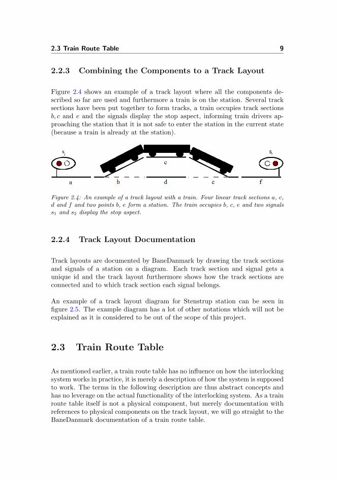
Figure 2.4 shows an example of a track layout where all the components de-scribed so far are used and furthermore a train is on the station. Several tracksections have been put together to form tracks, a train occupies track sectionsb, c and e and the signals display the stop aspect, informing train drivers ap-proaching the station that it is not safe to enter the station in the current state(because a train is already at the station).
Figure 2.4: An example of a track layout with a train. Four linear track sections a, c,d and f and two points b, e form a station. The train occupies b, c, e and two signalss1 and s2 display the stop aspect.
2.2.4 Track Layout Documentation
Track layouts are documented by BaneDanmark by drawing the track sectionsand signals of a station on a diagram. Each track section and signal gets aunique id and the track layout furthermore shows how the track sections areconnected and to which track section each signal belongs.
An example of a track layout diagram for Stenstrup station can be seen infigure 2.5. The example diagram has a lot of other notations which will not beexplained as it is considered to be out of the scope of this project.
2.3 Train Route Table
As mentioned earlier, a train route table has no influence on how the interlockingsystem works in practice, it is merely a description of how the system is supposedto work. The terms in the following description are thus abstract concepts andhas no leverage on the actual functionality of the interlocking system. As a trainroute table itself is not a physical component, but merely documentation withreferences to physical components on the track layout, we will go straight to theBaneDanmark documentation of a train route table.

10 Domain
Figure 2.5: The track layout for Stenstrup station. From left to right the track layouthas 4 linear track sections with id A12, 02, 04, B12, 2 points with id 01, 03, and 8signals with id a, A, E, F, G, H, B and b.

2.3 Train Route Table 11
2.3.1 Train Route Table Documentation
A train route table is a table where each row describes a single train route. Anexample of a train route table of Stenstrup station can be seen in figure 2.61.
The concept of a train route is the key idea behind an interlocking system; it isused to determine when and where trains can drive on a station. At first, wewill discuss some general concepts for train routes whereafter each column in atrain route table will be described.
2.3.1.1 Train Route Concepts
A train route is a description of:
� a set of track sections on a station that combined defines the route throughthe station that can be used by a train,
� conditions for locking the route,
� conditions for releasing the route,
� conditions for when signals can display the drive aspect and thus informtrain drivers that it is safe to enter a station.
When a route is locked and the signal displays the drive aspect, it means thata train can travel along the route safely i.e. the safety properties will not beviolated. When the train has reached the end of the route, the route is released.It is possible to lock several routes at a time if they are not conflicting. Twotrain routes are said to be conflicting if locking them at the same time potentiallyleads to a collision or a derailing.
BaneDanmark thus attempts to ensure that no collision nor derailing can happenby ensuring that no conflicting train routes are locked at the same time. Asmentioned in the introduction BaneDanmark has never formally verified whetherthe latter implies the former.
1BaneDanmark has two different definitions of what the plus and minus directions of pointsare – for more details see [5, 1]. The train route table has been slightly modified to use themost recent definition, which is used throughout this project.

12 Domain
Figure 2.6: Train route table of Stenstrup station.

2.3 Train Route Table 13
2.3.1.2 Train Route Table Columns
The meaning of the columns of a train route table will now be explained withthe fifth row in figure 2.6 as an example reference:
Togveje (Train routes) The nr sub column defines the id of the train route.Theid for the train route in the fifth row is thus 7. The next sub column withno header describes from which direction the train route will be entered orto which direction the train route will be exited, and furthermore whetherthe train route is an exit (Udk) or entry (Indk) route. Train route 7 isan exit route heading for Odense (til Odense). The column Spor defineswhich platform a train using the route is heading for, if it is an entryroute, or which platform the train is starting from, if it is an exit route.Trains on train route 7 are starting from platform 1 which is track section02 according to the track layout for Stenstrup in figure 2.5. The columnforløb defines whether the train route has a safety distance. A safetydistance is an additional track section that is added to the route to takeinto consideration that the train might not be able to break in time tostop at the platform. If the field has the value strækn a safety distanceis added, and if the field is empty there is no safety distance for the trainroute. Train route 7 does not have a safety distance.
Signaler (Signals) This column has a sub column for each signal on the station.For each train route it will be defined whether there are any requirementsfor the different signals. If the field for the signal is empty there are norequirements to which aspect the signal must display. Otherwise, the fieldwill contain the colour which the signal is required to display after thetrain route has been locked and all track sections used in the specific trainroute are free. For train route 7 it is required that signal E is green (gr)and F is red (rø) when the train route has been locked and track sectionsA12 and 01 are free.
Sporskifter (Points) This column has a sub column for each point on thestation. For each train route it will be defined whether there are anyrequirements for the point. If the field for the point is empty there areno requirements to which position the point must be in. Otherwise, if thefield contains a plus or a minus sign the point must be in either the plusor minus position respectively, in order for the train route to be locked.For train route 7 to be locked it is required that point 01 is in the plusposition2.
2Point S1/S2 is a point on a sidetrack of the station and as explained earlier this part ofthe domain is left out, as it is out of the score of this project.

14 Domain
Sporisolationer (Track sections) This column has a sub column for each tracksection on the station. A sub column is empty if there is no requirementfor the track section in order to allow a train to enter the train route.Otherwise, the symbol ↑ indicates that the track section must be free, i.e.not occupied by a train, in order for the associated signal to display thedrive aspect and allow a train to enter the train route. For train route 7it is required that track sections A12 and 01 are free.
Ovk (Crossings) This column has a sub column for each crossing on the station.If the field for a crossing is empty there is no requirement for the crossing.If the field has the value “Ja”, then the crossing must be free in order forthe train route to be locked. We consider crossings as being out of thescope of this project.
Stop fald (Stop drive aspect) This column defines that a signal must displaythe stop aspect when a specific track section is occupied. Occupied isdefined with ↓. For train route 7 signal E must display the stop signalwhen track section 01 is occupied.
Togvejsopl (Train route release) This column has two sub columns Indl andOpl. Indl defines the condition for when the release of the train routeis initiated, by defining a track section that must be occupied (↓) and atrack section that must be free (↑). Opl defines the condition for when therelease of the train route is finalised, by defining a track section that mustbe occupied and a track section that must be free. For train route 7 thecondition for initiating the release of the train route is that track section01 is occupied and track section A12 is free. The condition for finalisingthe release of the train route is that track section A12 is occupied andtrack section 01 is free.
Gensidige spærringer (Mutually conflicting train routes) This column de-fines which train routes are mutually conflicting. Figure 2.7 shows howthe conflicting train routes for train route 7. Fields containing a circlespecify that the train routes having the numbers to the right and abovethe field are conflicting, whereas empty fields specify train routes that arenot conflicting. Train routes conflicting with train route 7 are identified bylooking at the red boxes on figure 2.7. Train route 7 is mutually conflictingwith train routes 2, 3, 6 and 8.
The method used by BaneDanmark to ensure that the general safety propertiesare satisfied is thus to define a number of routes on a station and only allowtrains to use these routes if certain conditions are satisfied, such that the trainscan use the routes in a safe manner.

2.4 Circuit 15
Figure 2.7: This part of the train route table of Stenstrup station specifies which trainroutes are mutually conflicting. Fields containing a circle specify that the train routeshaving the numbers to the right and above the field are conflicting, whereas empty fieldsspecify train routes that are not conflicting. Train route 7 is mutually conflicting withtrain routes 2, 3, 6 and 8.
As previously mentioned the description of a train route table has no effect onhow an interlocking system actually works. Given a track layout an electricalcircuit must implement the requirements of a train route table such that therequirements are satisfied by the interlocking system. The electrical circuit willbe explained in the following section.
2.4 Circuit
The circuit of an interlocking system consists of a number of different types ofelectrical components connected with wires. The following sections will intro-duce the electrical components in the circuit, i.e. resistors, fuses, lamps, buttons,wires, relays and relay contacts.
2.4.1 Resistors
The purpose of resistors is to keep the circuit from short-circuiting.

16 Domain
2.4.2 Fuses
The purpose of fuses is to limit the damage made to a circuit in case of excessivecurrent.
2.4.3 Lamps
The lamps in the circuit are visible on the station via the signals on the tracklayout. The purpose of the lamps is thus to indicate to the drivers of the trainswhether it is safe to enter a station or not.
2.4.4 Buttons
When trains are approaching a station BaneDanmark personnel must be ableto inform the interlocking system which train routes should be locked suchthat they can control the train movements on the station. For this purposeBaneDanmark uses an operator’s panel, which displays the track layout of astation and has buttons used to switch points and to initiate the locking of trainroutes3. The operator’s panel for Stenstrup station can be seen in figure 2.8.Notice that the operator’s panel shows the track layout rotated 180◦ in relationto figure 2.5. This is presumably to display the station to the operator as seenfrom the physical location of the operator’s panel.
When a button on the operator’s panel is pushed, current can pass through thepart of the circuit which the button is connected to.
2.4.5 Wires
Wires connect the electrical components of a circuit. For each resistor, fuse,lamp, button, relay and relay contact at most 4 wires can be connected. Thepositive and negative poles can have any number of wires connected.
3Nowadays the push and release of buttons is automated.

2.4 Circuit 17
Figure 2.8: The operator’s panel from Stenstrup station. The thick lines are the tracksections of Stenstrup station and the circles on the black lines are buttons. There areeight buttons. For each track section connected to the open track there are two buttons“U” and “I” for exiting and entering the station. For each point there are two buttons“+” and “–” for the plus and minus position. The two platform buttons “T” are out ofthe scope of this project. For how to operate the buttons see section 2.7.
2.4.6 Relays and Relay Contacts
Relays are the most important components in a relay interlocking system. Be-sides being an electrical component itself it has a number of contacts that arealso electrical components. There are two types of contacts, upper contacts andlower contacts referring to their physical position on the relay. A relay has twosettings, drawn or dropped respectively. If a relay is drawn current can passthrough the upper contacts (we say the contacts are closed), but not throughthe lower contacts (we say the contacts are open). See [5] for a detailed descrip-tion of how a relay works. Vice versa, if a relay is dropped the lower contactsare closed and the upper contacts are open. It is possible for several relays todraw/drop at a time. According to Kirsten Mark Hansen from BaneDanmark amaximum of 5 relays can drop/draw at the same time in an interlocking systemdesigned by BaneDanmark.
Each relay in an interlocking system can be thought of as representing a booleanvariable. The value of the boolean variable is set to true when the relay is drawn,and false when the relay is dropped. The value of the boolean variable is readby using the contacts of the relay. Upper contacts read the value of the variablewhereas lower contacts read the negated value. Assume a relay A representsthe statement green lamp l is on. When A is drawn the lamp is on and anupper contact will represent this state, whereas a lower contact will representthe negated state. The same principle holds for when A is dropped.
There are two types of relays which will be explained in the following sections.
18 Domain
2.4.6.1 Regular Relays
When no current passes through a regular relay it is dropped. But when currentgoes through the relay it will change from dropped to drawn. When currentagain is cut from the relay it will change from drawn to dropped.
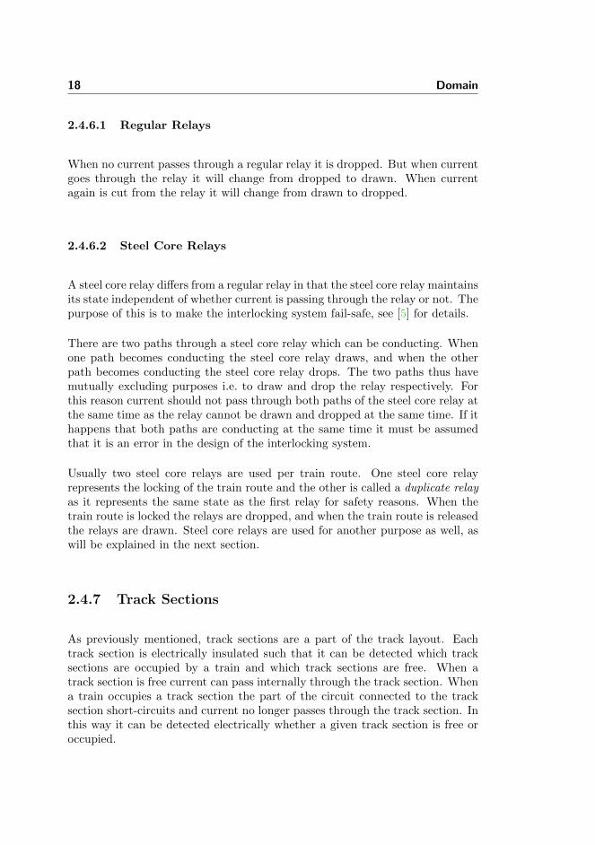
2.4.6.2 Steel Core Relays
A steel core relay differs from a regular relay in that the steel core relay maintainsits state independent of whether current is passing through the relay or not. Thepurpose of this is to make the interlocking system fail-safe, see [5] for details.
There are two paths through a steel core relay which can be conducting. Whenone path becomes conducting the steel core relay draws, and when the otherpath becomes conducting the steel core relay drops. The two paths thus havemutually excluding purposes i.e. to draw and drop the relay respectively. Forthis reason current should not pass through both paths of the steel core relay atthe same time as the relay cannot be drawn and dropped at the same time. If ithappens that both paths are conducting at the same time it must be assumedthat it is an error in the design of the interlocking system.
Usually two steel core relays are used per train route. One steel core relayrepresents the locking of the train route and the other is called a duplicate relayas it represents the same state as the first relay for safety reasons. When thetrain route is locked the relays are dropped, and when the train route is releasedthe relays are drawn. Steel core relays are used for another purpose as well, aswill be explained in the next section.
2.4.7 Track Sections
As previously mentioned, track sections are a part of the track layout. Eachtrack section is electrically insulated such that it can be detected which tracksections are occupied by a train and which track sections are free. When atrack section is free current can pass internally through the track section. Whena train occupies a track section the part of the circuit connected to the tracksection short-circuits and current no longer passes through the track section. Inthis way it can be detected electrically whether a given track section is free oroccupied.

2.4 Circuit 19
2.4.7.1 Track Sections and Regular Relays
When connecting a regular relay to the electrical path from a track section, therelay can be used as a variable monitoring whether current passes through thetrack section i.e. whether the track section is free. The contacts of the relaycan be used to read the state of the relay and thus of the track section. In aninterlocking system every track section is connected to a regular relay in thisway to be able to monitor the state of the track section.
2.4.7.2 Points and Relays
Two steel core relays are associated with each point, one for the plus positionand one for the minus position. If one of the steel core relays is drawn then thepoint is in the respective position. Additionally there are two regular relays, onefor the plus position and one for the minus position. These relays are duplicaterelays and they reflect the state of the steel core relays. If none of these fourrelays are drawn the point is in the intermediate position.
2.4.8 Circuit Documentation
The circuit of an interlocking system is quite complex and even a somewhatsimple station as Stenstrup station has a circuit that is documented on severaldiagrams. In figure 2.9 a part of one of the diagrams of Stenstrup station can beseen. The two relays are depicted with different symbols4. Likewise the contactsare depicted in different ways. This has no functional influence but is merelymeant to make the circuit more easy to read. The downwards arrows to the leftof the relays indicate that they are both dropped. A drawn relay will have anupwards arrow to the left.
In figure 2.9 it can be seen that the two relays have the same name, i.e. A. Theunique id of relays and contacts are made up of numbers denoted next to them.Figure 2.10 depicts how these numbers are combined to construct a unique idfor a relay. The relay in figure 2.11 will thus have id A-370 using the conventionof figure 2.10.
An example of a steel core relay from BaneDanmark’s diagrams can be seen infigure 2.13. The contact on the left of the diagram which does not have an id
4The reason for this is that the relays have different purposes. One symbol is used forrelays monitoring the state of a track section, one symbol for relays monitoring whether lampsare on etc. More information on the different symbols can be found in [5].

20 Domain
Figure 2.9: A part of the circuit documentation for Stenstrup station. The grey linesare wires, and the components not marked with an arrow are all contacts.
as normal contacts is contact number 1 on the steel core relay. Contact 1 of asteel core relay is always connected to the relay in this way. The component inthe path drawn to the left on the diagram is the dropping component whereasthe component in the path drawn to the right is a drawing component. To theleft side of the relay only contact 1 of the relay can be connected, whereas oneor two contacts can be connected to the right of the relay.

2.4 Circuit 21
Figure 2.10: The numbers uniquely identifying a relay have been replaced with lettersto show how the numbers should be combined to construct a compressed id for a relay.When combining the letters the unique id is name-hk1 if i = 1 ∧ j = 2 and name-hk0if i = 3 ∧ j = 4.
Figure 2.11: The unique id of the relay is A-370 when combining the numbers aroundthe relay as illustrated with figure 2.10.
Figure 2.12: An example of how a contact is documented by BaneDanmark. Thecontact is physically positioned on the relay in figure 2.11 which can be seen from thefact that the contact has the same id as the relay namely A-370. Additionally thecontact id is denoted next to the contact, here marked with a square, i.e. this contacthas id 1.
Figure 2.13: An example of how a steel core relay is documented by BaneDanmark.The electrical path to the left of the relay is the dropping path, and the electrical pathto the right of the relay is the drawing path.
22 Domain
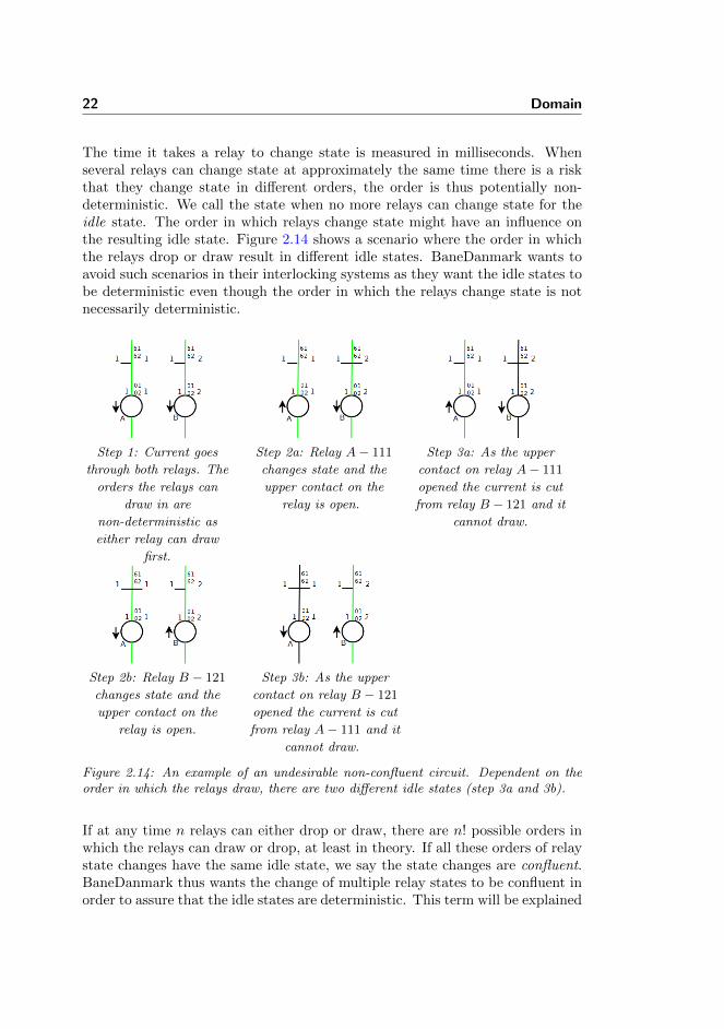
The time it takes a relay to change state is measured in milliseconds. Whenseveral relays can change state at approximately the same time there is a riskthat they change state in different orders, the order is thus potentially non-deterministic. We call the state when no more relays can change state for theidle state. The order in which relays change state might have an influence onthe resulting idle state. Figure 2.14 shows a scenario where the order in whichthe relays drop or draw result in different idle states. BaneDanmark wants toavoid such scenarios in their interlocking systems as they want the idle states tobe deterministic even though the order in which the relays change state is notnecessarily deterministic.
Step 1: Current goes
through both relays. The
orders the relays can
draw in are
non-deterministic as
either relay can draw
first.
Step 2a: Relay A− 111
changes state and the
upper contact on the
relay is open.
Step 3a: As the upper
contact on relay A− 111
opened the current is cut
from relay B − 121 and it
cannot draw.
Step 2b: Relay B − 121
changes state and the
upper contact on the
relay is open.
Step 3b: As the upper
contact on relay B − 121
opened the current is cut
from relay A− 111 and it
cannot draw.
Figure 2.14: An example of an undesirable non-confluent circuit. Dependent on theorder in which the relays draw, there are two different idle states (step 3a and 3b).
If at any time n relays can either drop or draw, there are n! possible orders inwhich the relays can draw or drop, at least in theory. If all these orders of relaystate changes have the same idle state, we say the state changes are confluent.BaneDanmark thus wants the change of multiple relay states to be confluent inorder to assure that the idle states are deterministic. This term will be explained

2.5 Trains 23
further in section 3.2.1.2.
2.5 Trains
Trains occupy and free track sections when driving through a station. Differ-ent trains can have different lengths and can thus occupy different numbers oftrack sections depending on the length of the train and the lengths of the tracksections, see figure 2.15.
Figure 2.15: Trains can occupy different numbers of track sections depending on thelength of the train and the lengths of the track sections.
2.6 Normal State of an Interlocking System
In BaneDanmark’s documentation of an interlocking system, the electrical com-ponents are always depicted in their normal state. The following list describesthe normal state of each component in an interlocking system:
Linear track sections are free.

24 Domain
Points are free and in the plus position.
Trains are not present on a station.
Signals are not displaying a drive aspect5.
Resistors cannot change state.
Fuse cannot change state.
Lamps have different normal states depending on their colour and purpose. Asthe normal state of signals is to not display the drive aspect, the greenlamps are turned off and the rest of the lamps are turned on.
Buttons are released.
Wires can be either conducting or non conducting in the normal state, depend-ing on whether the components it is connected to are conducting.
Regular relays are dropped if they are not conducting and drawn it they areconducting.
Steel core relays are all drawn in the normal state except steel core relaysfor the minus position of points. The reason for this is that a drawn steelcore relay for a point position indicates that the point is currently in thatposition, and as a point cannot be in both the plus and minus position atthe same time, only one of the steel core relays can be drawn at a time.
2.7 Using an Interlocking System
In this section an example of a scenario on Stenstrup station will be explainedin order to combine the different areas of an interlocking explained so far.
In the scenario a BaneDanmark operator wants to allow a train to enter Sten-strup station from Odense and to drive to platform 2. For this example it isassumed that the interlocking system is initially in the normal state and thateach track section and the train has length N . The steps in this process aredenoted in chronological order below:
1. Select the relevant train route:
5The phrasing not displaying a drive aspect is deliberately used instead of the phrasingdisplaying a stop aspect as only a yellow lamp will be on in some signals in the normal state.As mentioned previously we only consider drive and stop aspects though.

2.7 Using an Interlocking System 25
Actor BaneDanmark operator.
Reference Train route table figure 2.6 on page 12.
Result There are two train routes that use the track sections from Odenseto platform 2, i.e. entry train route 3 and exit train route 8 as seen inthe train route table. As the train is going to enter the station onlytrain route 3 applies.
2. Switch points to the relevant positions:
Actor BaneDanmark operator.
Reference Train route table figure 2.6 on page 12 and operator’s panelfigure 2.8 on page 17.
Result In the description of train route table 3 it is noted that point 01should be switched to the minus position and point 03 to the plusposition. In order to switch the points the corresponding buttons onthe operator’s panel are pushed, i.e. the – button for point 01 andthe + button for point 03.Relays in the interlocking system change state because the buttonswere pushed. The relay state changes cause the points to switch tothe relevant positions.
3. Initiate locking of the relevant train route:
Actor BaneDanmark operator.
Reference Operators panel figure 2.8 on page 17.
Result An entry or exit button (see section 2.4.4 for a description of op-erator’s panel buttons) must be pushed to initiate the locking of atrain route. In this way the operator has indicated where the trainenters or exits the station. The BaneDanmark operator pushes inthis case the entry button at the track section connected to the opentrack from Odense.Relays in the interlocking system change because a button was pushed.The relay state changes cause a train route to be locked.
4. Enter Stenstrup station:
Actor A train entering Stenstrup station from Odense.
Reference Track layout figure 2.5.
Result Track section A12 is occupied by the train.Relays in the interlocking system change state due to the occupationof a track section. The relay state changes cause signal A to dis-play the stop aspect. This will indicate to other trains approachingStenstrup from Odense that it is not safe to enter the station.

26 Domain
5. Drive further into Stenstrup station:
Actor The train that occupies track section A12.
Reference Track layout figure 2.5.
Result Track section 01 is occupied by the train and track section A12is free again.Relays in the interlocking system change state due to the occupationand freeing of track sections. The relay state changes initiates therelease of the train route.
6. Drive further into Stenstrup station:
Actor The train that occupies track section 01.
Reference Track layout figure 2.5.
Result Track section 04 is occupied by the train and track section 01 isfree again.Relays in the interlocking system change state due to the occupationand freeing of track sections. The relay state changes finalise therelease of the train route.

Chapter 3
Modelling Language
In order to be able to specify a model of a relay interlocking system and subse-quently verify certain safety properties of this model, the first task is to decideon the modelling language to use.
Section 3.1 discusses three different languages suitable for this project and listssome pros and cons of each language. The section ends with a discussion onwhich language is picked and why.
Section 3.2 describes the theory behind the chosen modelling language.
Section 3.3 goes into detail with a technical introduction and guide to how thelanguage is used. This section should provide the reader with enough knowledgeabout the modelling language to understand the remaining parts of the reportwhere the language is used. Chapter 5 describes how the language is used tospecify a model of a interlocking system and chapter 7 explains how model-checking is performed on the final model.

28 Modelling Language
3.1 Considered Specification Languages
When deciding which specification language to use a number of considerationsneed to be made. What type of system is the specification language goingto model? What requirements are there to the system and model? How canthe the model be handled, checked or verified? The rest of this section andthe following sections describe how we have answered these questions, whichspecification language we have chosen and why.
The system that we are going to model in this project is highly safety critical.The main purpose is, as described earlier, to verify a number of safety prop-erties of the system. It is highly advisable when modelling such safety criticalsystems to model them using formal methods [21]. One of the strengths of for-mal specification languages is that they provide the ability to specify systems atan abstract level and then check whether certain properties hold or not. Mainlybecause of these reasons, we have chosen to use a formal specification languagefor modelling and verifying interlocking systems.
Three specification languages have been considered for modelling interlockingsystems, i.e. the RAISE Specification Language (RSL) [25], CafeOBJ [6, 16] andMaude [3, 20]. In the following sections the strengths and weaknesses of eachof these languages will be discussed briefly and based in this the specificationlanguage for the domain will be chosen.
3.1.1 RSL
The reason RSL seems natural to consider for this domain is that the authors areacquainted with RSL and because a part of the railway network has successfullybeen modelled using this language [1]. The possibility here is then to extendthe existing work by modelling the remaining parts of the network.
RSL provides the ability to specify systems on different abstraction levels. Inthe lowest abstraction level RSL is very expressive. This is very useful whenone wants to formalise a detailed system or when a highly expressive formallanguage is needed, e.g. to specify existential or universal quantifiers, as theseoperators are not supported by all relevant formal languages.
The RSL-SAL tool provides model checking facilities for RSL specifications [8].An advantage of this tool is that it allows the verification of properties in theearly states of developing the model. Some of the disadvantages with this tool isthat it is does not allow recursive or iterative functions and there is a restriction

3.1 Considered Specification Languages 29
of which data structures are allowed.
3.1.2 CafeOBJ
CafeOBJ is not nearly as expressive as RSL. CafeOBJ is the first of two termrewriting systems [26] that we will consider in this chapter. In short a rewritingsystem is a reduction system that is built-up using variables, constants andrewriting equations. These equations rewrite terms and values when certainrequirements are satisfied. Furthermore, CafeOBJ uses ordered sorts by sub-typing, which is very powerful [16, 4]. This means that a number of sorts canbe declared to represent different “types”. These sorts can then afterwards berelated to each other by specifying that one sort is included in another sort, etc.E.g. a sort cars is included in another sort vehicles.
The strength of CafeOBJ lies in its ability to exploit its rewriting system toperform inductive proofs. Examples of this can be seen in [22]. The languageprovides the possibility to specify proof scores. A proof score is a sequence ofsub proofs, which combined make up a proof [6]. If we choose to use CafeOBJwe have the option to specify the relay interlocking system in a generic way,which probably will be fairly difficult. If managing to do so though, it wouldbe possible with one proof to determine whether every relay interlocking systemmeeting the specified requirements would be safe or not.
3.1.3 Maude
Just like CafeOBJ, Maude is a term rewriting system supporting ordered sortsby sub-typing and the syntax and use of the language is almost identical toCafeOBJ. This is mainly because both languages originate from the same lan-guage, OBJ. Some of the main differences are the more powerful rewriting engineof Maude, Maude’s ability to work on objects and CafeOBJ’s theorem provingvs. Maude’s model checking techniques [17].
When one wants to represent a state of a system it can be done in Maude by acollection of objects each having a number of attributes and values. This makesit easy to specify (and read) a state. Additionally, Maude supports recursiveequations and provides a number of built-in modules e.g. modules to performmodel checking using LTL formulae.
As opposed to CafeOBJ, the main purpose of Maude is not to execute proofscores. Maude is more focused on model checking. This means that by choosing

30 Modelling Language
Maude we would not be able to prove that something holds for all relay inter-locking systems meeting certain requirements but rather whether a given relayinterlocking system satisfies the safety properties.
3.1.4 Making the Choice
As we are acquainted with RSL and this language has been used in anotherproject related to this [1], choosing RSL would be rather obvious. But as moreformal languages have been developed and have different pros and cons we de-cided to have a look at these languages in order to find out which languages aresuited for this task and project.
As both CafeOBJ and Maude are fairly new to us, we participated in an ad-vanced school on Formal Specification and Systems verification and looked intowhat features these languages could provide us with in relation to e.g. RSL. Af-terwards, we spend some time on getting acquainted with the two new languagesto be able to make a reasoned and factual choice of modelling language. Whenconsidering the possible outcomes of using either of these languages, CafeOBJwould allow us to create a generic specification and use proof scores to verifywhether every station is safe or not, but at the cost of time, as this process isvery time consuming. On the other hand, Maude would allow us to model checka specific station and verify whether this station is safe or not, but this processshould be less time consuming than the one for CafeOBJ.
The previous sections explained briefly which advantages and drawbacks thethree languages have. Even though we have a fairly good knowledge about RSLand only limited knowledge about how CafeOBJ and Maude work, we expectthat Maude will have some advantages to the other languages, e.g. in havingthe option to specify objects and built-in support for model checking with LTLformulae. For this reason we decided to use Maude as our modelling language.
3.2 What is Maude
In section 3.1.3 we very briefly explained Maude along with some advantages anddrawbacks of using this language. In this section we will give more theoreticalintroduction to what Maude is, to prepare the reader for the more technicalintroduction given in section 3.3.

3.2 What is Maude 31
3.2.1 Term Rewriting System
As mentioned Maude is a term rewriting system (from now on abbreviated toTRS). The TRS contains a set of axioms of the form x→ y. A subset of theseaxioms are simplification rules or rewrite rules. Some axioms can be conditional(of the form x→ y if c, meaning that some guard c must be true in order for theaxiom to be applicable. For an axiom to qualify as a simplification or rewriterule two conditions must hold:
1. Every variable occurring in y or c must exist in x. If this condition is notfulfilled, a rewrite sequence might not necessarily reduce terms as they canbecome non-ground. A ground term is a term containing only constantsand operators (i.e. no variables).
2. x may not be a single variable. If this condition is not fulfilled, everyterm will be able to match x, and thus the rewrite sequence will neverterminate.
The order in which simplification and rewrite rules are applied is non-deterministic.For the TRS to be sound it is required that it is terminating and Church-Rosser [2]. That a TRS is Church-Rosser means that it is confluent and sort-decreasing. These terms will be explained in the following sections.
3.2.1.1 Terminating
The meaning of the term “terminating” is as in the usual interpretation of theword, i.e. a TRS is terminating if no infinite sequence of simplification rulesexist. Inversely, a TRS is said to be non-terminating if a term exists, which canbe rewritten infinitely many times.
3.2.1.2 Confluence
A TRS is said to be confluent if any two rewrites of a term can always be unifiedby further rewriting, regardless of the order in which the simplification rules areapplied. Another explanation is that “no matter how two paths diverge from acommon ancestor, the paths are joining at some common successor”according to[27]. Figure 3.1 shows terms and rewrites as a graph, where the nodes (letters)are terms and the arrows are rewrites. If term a can be rewritten to any termb in one rewrite sequence and to any term c in another rewrite sequence, then

32 Modelling Language
for a to be confluent, it must be possible to unify b and c by further rewriting.This property is very important for TRSs as we have no control over the orderin which the applicable simplification rules are applied.
Figure 3.1: Letters symbolise terms and arrows symbolise rewrites. For a to be con-fluent, any term rewritten from a must unify to a term d by further rewrites. The *indicates there may be any number of rewrites between the terms.
3.2.1.3 Sort-Decreasing
Sort-decreasing means that any sort, Sx, has only a finite number of sub sorts,i.e. the sort declarations cannot be cyclic [19].
S0 < . . . < Sx−1 < Sx < . . .
Sub sorting is explained in section 3.3.2.
3.2.2 Verification
Maude provides several types of verification methods such as e.g. theorem prov-ing and model checking. Theorem proving provides the option to verify whetherall stations are safe. Though, this would require a generic description of inter-locking systems and such a description does not exist at the current point.
The model checking tool in Maude generates a Kripke structure from the Maudespecification whereafter properties of the system can be verified by model check-ing LTL (Linear Temporal Logic) formulae in the Kripke structure. Section3.2.2.1 will give a formal definition of a Kripke structure and section 3.2.2.2 will

3.2 What is Maude 33
give a formal definition of LTL. Further details of how model checking works inMaude will be given in section 3.3.10.
3.2.2.1 Kripke Structures
A Kripke structure is a non-deterministic finite state machine.
Formally a Kripke structure is a 4-tuple [14]:
M = (S, I,R, L)
where S is a finite set of states, I is a set of initial states, R is a transitionrelation and L is a labelling function. Furthermore I ⊆ S, R ⊆ S × S andL : S → 2AP where AP is a set of atomic propositions. As seen from thedefinition L will, for each state, return a set of atomic propositions that holdin the state. Propositions that are not in a set of propositions for a given stateare implicitly assumed not to hold in the state. A Kripke structure must becomplete, i.e. each state must have an outbound transition.
How a Kripke structure M = (S, I,R, L) is specified in Maude will now beoutlined and thereafter elaborated by the following sections. In Maude the setof states S is defined by specifying a sort to represent the states. Sorts aredescribed in section 3.3.2. The set of initial states I is not explicitly defined,but when performing a model check with the modelCheck operator, as describedin section 3.3.10.3, the state from which the LTL verification starts is defined.The transition relation is defined with rules as described in section 3.3.6 andthe labelling function L is defined with an equation for satisfaction, see section3.3.10.1.
3.2.2.2 LTL
LTL (Linear Temporal Logic) reasons about linear models [7]. The opera-tors of LTL presented here are ©(next-time operator), 3(sometime operator),2(always operator), ∪ (until operator) and R (release operator).
The formal grammar of LTL is [7]:
ϕ ::= false|true|p| ∼ ϕ|ϕ ∧ ϕ|ϕ ∨ ϕ| © ϕ|3ϕ|2ϕ|ϕ ∪ ϕ
where p is an atomic proposition representing a boolean statement e.g. “thesun is shining” . The release operator is defined in terms of the until operatorϕ1Rϕ2 ::=∼ (∼ ϕ1∪ ∼ ϕ2).

34 Modelling Language
The notation σ, i |= ϕ will be used to denote that ϕ holds in state i in thestructure σ. As Maude verifies LTL formulae in a Kripke structure, σ representsthe Kripke structure ϕ will be verified in, starting from state i. The set ofpossible atomic propositions is denoted AP.
The formal definition of the operators are:
σ, i |= p iff p ∈ σ(i), for every p ∈ AP,
σ, i |=∼ ϕ iff σ, i 6|= ϕ,
σ, i |= ϕ1 ∧ ϕ2 iff σ, i |= ϕ1 and σ, i |= ϕ2,
σ, i |= ϕ1 ∨ ϕ2 iff σ, i |= ϕ1 or σ, i |= ϕ2,
σ, i |=©ϕ iff σ, i+ 1 |= ϕ,
σ, i |= 3ϕ iff there is a j ≥ i such that σ, j |= ϕ,
σ, i |= 2ϕ iff for all j ≥ i, we have σ, j |= ϕ,
σ, i |= ϕ1 ∪ ϕ2 iff there is a j ≥ i such that σ, k |= ϕ1 and σ, j |= ϕ2 for all i ≤ k < j
E.g.©ϕ holds in state i iff ϕ holds in state i+1. Implication is defined in termsof negation and disjunction: σ, i |= ϕ1 → ϕ2 iff σ, i |=∼ ϕ1 ∨ ϕ2.
3.3 Introduction to Maude
This section gives a technical introduction to the parts of Maude used in thisproject, i.e. to the syntax of Maude, how Maude is used to specify states andhow rewriting, searching and model checking is performed on a model. Maudeit self is rather extensive and contains a lot of options and possibilities whenspecifying a model.
Maude exists in two “versions”, Core Maude and Full Maude. Core Maudespecifies all the basic functionality whereas Full Maude is an extension to CoreMaude. This extension is written solely in Core Maude. As this project onlyuses the functionality available in Core Maude, only Core Maude is explained inthis report. In the remainder of this report Core Maude will simply be referredto as Maude.
Some of the topics discussed in the following subsections are the building blocksof a specification (modules), the types of variables and constants (sorts), simpli-fication rules (operators and equations) and transition rules (rules). The finalsubsections describe how all of this can be used to create a specification anddetermine whether certain properties are satisfied or not.

3.3 Introduction to Maude 35
3.3.1 Modules
A specification in Maude is composed by one or more building blocks calledmodules. Below two very simple and shortened modules NAT and COUNTER arespecified. The first module, NAT,
mod NAT is
*** Sorts , operators , equations , rules , etc.
endm
contains the code needed to perform basic operations on natural numbers, e.g.addition and multiplication. The possible content of modules is explained later.These basic operations might be needed by other modules, and instead of havingto copy the content of NAT into every module that uses natural numbers, Maudesupports inclusion. Note that -- or *** indicates that the rest of the line is acomment and is ignored by Maude. The second module, COUNTER,
mod COUNTER is
pr NAT .
*** Sorts , operators , equations , rules , etc.
endm
needs natural numbers and operations on them when counting numbers, andhence it includes (or protects) the module NAT. A module cannot be instanti-ated. One could then argue why modules are needed at all. To some extentthey are not necessary, except that we need at least one module containing ourspecification. Then it would be possible to specify everything within one mod-ule. But dividing a large specification up into multiple modules will make itmuch more readable and easier to modify/replace parts of it.
Note, that every specification line within a module must be succeeded by a blankcharacter and a dot to end the line.
Maude provides a large number of built-in modules. The ones used in thisproject or mentioned in the report can be found in appendix D.
3.3.2 Sorts
Instead of having types Maude provides sorts. Sorts can be understood as acollection of implicit and unknown values. In the following snippet of the NAT

36 Modelling Language
module the sorts Nat, Zero and NzNat (non-zero nat) are declared:
sort Nat .
sorts Zero NzNat .
A single sort is declared by preceding it with the keyword sort and multiplesorts can be declared on the same line using the keyword sorts and separatingeach sort by blanks. It does not make any difference whether sorts are declaredin one or the other way.
When sorts are declared one can specify one or more of the sorts to be subsortsof other sorts using the keywords subsort or subsorts. The following snippetspecifies that Zero and NzNat are subsorts of Nat:
subsorts Zero NzNat < Nat .
The above snippet does however not specify any relation between Zero andNzNat. Another way of specifying the exact same subsorts is:
subsort Zero < Nat .
subsort NzNat < Nat .
Figure 3.2 shows a graphical representation of three sorts and their relations.One advantage of having one sort subsort another sort is that every operator
Figure 3.2: A Venn diagram showing the relations between sorts. “Vehicle” is thesupersort of both “Car” and “Bus”. No relation is specified between “Car” and “Bus”which makes these sorts disjoint by definition.
taking the supersort as argument also accepts the subsort, as all (implicit) valuesof the subsort are also contained in the supersort. This is exemplified by theexplanation of a variable (V@Relay) on page 84.

3.3 Introduction to Maude 37
Consider the module snippets in section 3.3.1. Every sort declared in moduleNAT can be used and subsorted in both NAT and COUNTER as NAT is included inCOUNTER.
3.3.3 Variables
When sorts have been declared in the specification one can easily specify vari-ables. These variables can be used in equations (see section 3.3.5) and rules (seesection 3.3.6).
The following snippet declares variables N1 and N2 of sort Nat and variable NzN
of sort NzNat:
vars N1 N2 : Nat .
var NzN : NzNat .
The keywords var and vars are succeeded with a blank separated list of variablenames. Variables cannot be instantiated or manually given a value. They areused when matching and are automatically assigned to the matched values byMaude. The following sections will go further into detail with how this works.
Every variable is visible and usable only within the module it is declared. Alter-natively, variables can be declared on-the-fly like “N1:Nat” where N1 is the vari-able of sort Nat. Wherever an on-the-fly variable is used it has to be declared.Every on-the-fly variable is only usable within the same operator, equation,command, etc. it is declared.
3.3.4 Operators
Maude allows declaration of operators. The syntax of an operator is
op 〈Name〉 : 〈Sort1〉 . . . 〈Sortk〉 -> 〈Sort〉 [〈Attributes〉] .
〈Name〉 specifies the name of the operator and 〈Sort1〉 . . . 〈Sortk〉 specify thearity (i.e. the sorts of the arguments) of the operator. The final sort 〈Sort〉specifies the coarity (the sort of the result) of the operator. When specifyingoperators it is optional to specify the 〈Attributes〉. These are used to e.g. informMaude on how this operator should be interpreted. See section 3.3.7 for furtherinformation on these attributes.
38 Modelling Language
In Maude operators can be specified as prefix, infix, postfix or a combination ofthese (mixfix) operators. This is done by indicating with underscores where inthe name of the operator the different arguments should appear. When doingso, the number of underscores must match the arity of the operator. An exampleof this could be the following signature of addition:
op _+_ : Nat Nat -> Nat [assoc comm] .
This mixfix notation can be used to improve readability and comprehensibilityof the specification.
If one needs to specify multiple operators with the same signature this can bedone by specifying multiple almost identical lines, like the one above, or on oneline by exchanging op with ops and listing all operator names before the colon.These need not all be of the same type (prefix, mixfix, etc.), but can be of anytype of operator.
Operators with an arity of 0 (no arguments) are called constants. An exampleof a constant is:
op 0 : -> Zero .
This makes the term 0 a constant of the sort Zero. Before this operator decla-ration 0 would not be recognised as a term.
3.3.5 Equations
As mentioned in section 3.3.4 simplification rules are in Maude called equations.The syntax of an equation is:
eq 〈Term1〉 = 〈Term2〉 [〈Attributes〉] .
In order for an equation to be executable by Maude (as mentioned in section3.2.1) any variables appearing on the right hand side of the equation must bespecified on the left hand side. 〈Attributes〉 is optional and more informationon what this specifies can be found in section 3.3.7. An example of an equationis:
var N : Nat .
eq N + 0 = N .

3.3 Introduction to Maude 39
This equation specifies that an addition between any number, N, and our con-stant 0 can be rewritten to N. Remember that in order for this equation tobe valid and understandable by Maude, the variable N must be declared as avariable (see section 3.3.3).
Equations can also be specified as conditional equations if one wants a guardprotecting the equation. The syntax of such a conditional equation is verysimilar to the one of a regular equation:
ceq 〈Term1〉 = 〈Term2〉 if 〈Guard〉 [〈Attributes〉] .
The keyword eq has been replaced by ceq and following the second term is thekeyword if succeeded by the boolean guards (〈Guard〉) of the equation. Anexample of a conditional equation is the following equation to find the largestof two natural numbers:
vars N M : Nat .
op _max_ : Nat Nat -> Nat .
ceq N max M = N if N >= M .
ceq N max M = M if N < M .
3.3.6 Rules
In Maude rules are used to describe possible transitions between states. Thesyntax of a rule is:
rl [〈Label〉] : 〈Term1〉 => 〈Term2〉 [〈Attributes〉] .
The part“[〈Label〉] :”does not provide any functional effect and can be omitted.Labelling rules is very useful for tracing searches though which is mentioned insection 3.3.10. Note that equations are always prioritised to rules, such that ifany rewriting can be applied to a term this is done prior to applying any rule. Arule can be applied if 〈Term1〉 matches a part of the current state of the system(or the entire state). If this is the case and the rule is applied, the matchedfragment is replaced by 〈Term2〉 of the fragment.
The syntax of equations and rules is almost identical. The difference lies in theway Maude uses equations and rules to rewrite terms. One interesting differenceis that Maude always simplifies a term as much as possible (using equations)before applying any rules. This means that if at any time both an equation anda rule applies to a term, the equation will be applied prior to the rule. Anotherinteresting difference is that if more equations apply to the same term, Maude

40 Modelling Language
only applies one of them. Note that, as described in section 3.2.1, a specificationin Maude is only sound if it is confluent, and thus regardless of which orderthe equations are applied on a term by Maude, the rewritings should at somepoint unify to the same resulting term. On the other hand, rules define thepossible transitions between states, and therefore whenever two or more rulesare applicable, both rules will be applied. For this reason rules are not requiredto be confluent.
The following PERSON module is a simple example of a module with rules:
mod PERSON is
sort Location .
ops atHome atShop atWork : -> Location .
rl [gotoWork] : atHome => atWork .
rl [doWork] : atWork => atWork .
rl [leaveWork] : atWork => atHome .
rl [gotoShop] : atHome => atShop .
rl [doShop] : atShop => atShop .
rl [leaveShop] : atShop => atHome .
endm
The sort Location is used to represent the states of the system. The modulespecifies three states, atHome, atShop and atWork, and six transitions betweenthese states. The corresponding Kripke structure can be seen in figure 3.3.
Figure 3.3: The Kripke structure corresponding to the PERSON module.
Just as equations, rules can also be conditional. The syntax for conditional rulesis:
crl [〈Label〉] : 〈Term1〉 => 〈Term2〉 if 〈Guard〉 [〈Attributes〉] .
The only differences between the unconditional and conditional rules are thereplacing of rl with crl and the succeeding if keyword and 〈Guard〉 term.When Maude tries to apply a rule it starts out by matching 〈Term1〉 with thecurrent state. If this matches it evaluates the guard, and only if this can berewritten to the boolean term true, 〈Term1〉 is replaced by 〈Term2〉. Thelabel of a conditional rule is optional as it is for the unconditional rule. Thefollowing module PERSON2 is almost equal to the module PERSON except that the

3.3 Introduction to Maude 41
person can earn money by working (the doWork rule) and in order to buy itemsin the shop (the doShop rule) the person needs money.
mod PERSON2 is
pr INT .
sorts Location Bag .
ops atHome atShop atWork : -> Location .
op bag : Int Int -> Bag .
op _&_ : Location Bag -> Location .
vars C I : Int .
rl [gotoWork] : atHome => atWork .
rl [doWork] : atWork & bag(C, I) => atWork & bag(C + 1, I
) .
rl [leaveWork] : atWork => atHome .
rl [gotoShop] : atHome => atShop .
crl [doShop] : atShop & bag(C, I) => atShop & bag(C - 1,
I + 1) if C > 0 .
rl [leaveShop] : atShop => atHome .
endm
The bag operator takes two integers as arguments. The first is the amount ofcoins in the bag and the second argument is the amount of items in the bag.The rule doWork has been extended to require having a bag of C coins and I
items. As these are variables they can match any integer. If this rule is appliedthe person stays atWork but gets the bag updated to have one more coin (C+ 1) and the same amount of items (I). But the more interesting part is thedoShop rule which has been converted to a conditional rule. In order for the ruleto apply two conditions must be fulfilled. Firstly, the person must be atShop
and have a bag containing C coins and I items. Secondly, the condition C > 0
must be true. This means in words, that the person must have at least 1 coinin the bag in order to buy an item. If this condition can be rewritten by Maudeto evaluate to the boolean term true, the bag is updated to have one less coinin it (C - 1) and one more item (I + 1).
When having a specification like this it is possible to have Maude check if itgiven a specific state is possible to reach another state or to check if certainpropositions hold in every subsequent state etc. This can be done using some ofMaude’s built-in commands combined with the built-in modules SATISFACTIONand LTL. All of this is described in sections 3.3.9 and 3.3.10.

42 Modelling Language
3.3.7 Attributes
Maude provides many attributes, but only the ones used in this project arementioned below. The following attribute applies to equations:
[owise] Equations with this attribute are only executed by the rewrite engineif no other equation applies. Sometimes, equations can easily be definedfor some cases whereas others are more difficult or cumbersome to define.Then it might make sense to define an equation with the owise attributeto specify that this equation should only apply if no other applies. Anexample of this is:
var N : Nat .
op s : Nat -> NzNat .
op even : Nat -> Bool .
eq even(s(s(N))) = even(N) .
eq even (0) = true .
eq even(N) = false [owise] .
The s operator should be understood as defining the successor of a givennatural number. By using the last equation the operator even is definedfor all possible values.
The following attributes apply to operators:
[assoc] Declares that the arguments of the operator are associative.
[comm] Declares that the arguments of the operator are commutative.
[ctor] Specifies that the operator is a constructor. It is rather complicatedto determine which operators should be specified as constructors. Moreinformation on the attribute can be found in [3] and [20].
[id: 〈Term〉] This attribute declares that 〈Term〉 is the identity element ofthe operator. It is used in e.g. the built-in module SET where the constantempty is the identity element of the operator concatenating elements orsets to a new set.
[gather (〈Seq〉)] This attribute is used to restrict the precedence of the ar-guments of the operator. 〈Seq〉 is a sequence of either E, e or & and thelength of the sequence must exactly match the number of arguments ofthe operator. The first element in the sequence restricts the first argumentetc. The elements have the following meaning:

3.3 Introduction to Maude 43
� E means that the precedence of the argument must be lower than orequal to the precedence of the operator.
� e means that the precedence of the argument must be strictly lowerthan the precedence of the operator.
� & means that the argument can have any precedence.
[memo] The purpose of this attribute is to improve performance of the rewrit-ing engine by trading off memory for time. For an operator having thisattribute, whenever Maude encounters a subterm having this operator atthe top it stores the canonical form of the subterm along with the canoni-cal form of the result of rewriting the subterm. “On top” means the outermost operator on a term, e.g. the top most operator on
(3 + 4) max 6
is the _max_ operator. Whenever Maude then encounters the same sub-term it looks up whether a result has been stored for this subterm and ifso this result is used and not recalculated. This saves a number of rewritesas equational simplification need not be done more than once for the samecanonical subterm having this operator at the top.
3.3.8 Configurations
Maude provides a built-in module CONFIGURATION that allows for specifyingobjects. The most interesting part of the module is:
mod CONFIGURATION is
sorts Attribute AttributeSet .
sorts Oid Cid Object Configuration .
subsorts Attribute < AttributeSet .
subsorts Object < Configuration .
op none : -> AttributeSet [ctor] .
op _‘,_ : AttributeSet AttributeSet -> AttributeSet [
assoc comm id: none ctor] .
op <_:_|_> : Oid Cid AttributeSet -> Object [ctor] .
op none : -> Configuration [ctor] .
op __ : Configuration Configuration -> Configuration [
assoc comm id: none ctor] .
endm
A configuration is a multiset of objects that could represent a state of a system.A configuration has the form none or o1 o2 · · · on where n ≥ 1 and oi is an

44 Modelling Language
object (of sort Object). Each object is specified using the operator <_:_|_>.The first argument of this operator is the object identifier (of sort Oid), thesecond argument is the class identifier (of sort Cid) and the last argument is aset of attributes (of sort AttributeSet). An attribute set has the form none ora1 a2 · · · an where n ≥ 1 and ai is an attribute (of sort Attribute).
For each individual specification, specific constructors for the object id, class idand attributes must be given. Imagine that we want to redefine the PERSON2
module from section 3.3.6 and instead want to have persons represented as ob-jects. An advantage of this is that we can now have multiple persons representedin our state and each one has an associated amount of coins and items. Such amodule could look like this:
mod PERSON3 is
pr CONFIGURATION .
pr INT .
sort Location .
ops atHome atShop atWork : -> Location .
op Person : -> Cid .
ops p1 p2 : -> Oid .
op location :_ : Location -> Attribute .
op coins :_ : Int -> Attribute .
op items :_ : Int -> Attribute .
*** Rules are described below
endm
The first change is that the module includes the CONFIGURATION module. Thenext changes are on lines 6 and 7 which specify the constants Person (of sortCid) and p1 and p2 (of sort Oid). The following three lines specify the attributesused to store information on the location of the person and the amount of coinsand items that the person carries around.
After having specified this module, a person staying at home and having zerocoins and items can be specified as:
< p1 : Person | location : atHome , coins : 0, items : 0 >
Now, the only things we need to update in PERSON3 are the rules. They need tobe updated to handle the configurations. The following shows three of the sixupdated rules. The rest of the rules can be seen in appendix F.1.
var P : Oid .

3.3 Introduction to Maude 45
vars C I : Int .
rl [gotoWork] :
< P : Person | location : atHome , coins : C, items : I >
=>
< P : Person | location : atWork , coins : C, items : I >
.
rl [doWork] :
< P : Person | location : atWork , coins : C, items : I >
=>
< P : Person | location : atWork , coins : (C + 1), items
: I > .
crl [doShop] :
< P : Person | location : atShop , coins : C, items : I >
=>
< P : Person | location : atShop , coins : (C - 1), items
: (I + 1) >
if C > 0 .
The first rule, gotoWork, shows how an unconditional rule on configurationscan be specified. In order for the rule to be applicable the configuration mustcontain an object of a person having the location value atHome and any numberof coins and items. When the rule is applied, the person object is replaced bya new person object identical to the first one except that the location value hasbeen changed to atWork.
For the second rule, doWork, to be applicable the configuration must containa person who is at work (location : atWork). When the rule is applied theperson object is replaced by a new person object having an incremented amountof coins.
The third and final rule, doShop, is applicable if the configuration contains aperson P who is at the shop. This is a conditional rule and is only applicable ifthe condition (C > 0) rewrites to the boolean term true. The result of applyingthis rule is, as with the first two rules, that the person object is replaced by anew updated person object.
Every object created must have an id (Oid) to identify the specific object. Inthe above examples constants are used as the id. A disadvantage of this is thatin order to add a new object and thus a new Oid of the object, a new constantmust be declared. An alternative way to create these id is to use the built-inmodule QID (short for quoted id) by rewriting the PERSON3 module to:

46 Modelling Language
mod PERSON3 -QID is
pr CONFIGURATION .
pr INT .
pr QID .
sort Location .
subsort Qid < Oid .
ops atHome atShop atWork : -> Location .
op Person : -> Cid .
op location :_ : Location -> Attribute .
op coins :_ : Int -> Attribute .
op items :_ : Int -> Attribute .
*** Rules left out for simplicity
endm
The new lines in this module specify that the module QID is included (or ratherprotected), the sort Qid from the QID module is declared as a subsort of Oid
and no Oid constants are declared. This means that any term starting with aquote (’) are accepted as an Oid and the following configuration is valid eventhough ’p1 and ’p2 have not been declared as constants:
< ’p1 : Person | location : atHome , coins : 0, items : 0 >
< ’p2 : Person | location : atHome , coins : 2, items : 3 >
The entire module PERSON3-QID can be seen in appendix F.2
3.3.9 Commands
Maude provides a number of commands that can be used to either load modulesinto Maude or to work with previously defined modules. The following sectionsdescribe the most interesting ones and the ones used in this project. All of themcan be used after having installed and started Maude as described in section B.
3.3.9.1 Reduce
The command reduce (abbreviated red) is one of the most simple commandsfor interacting with Maude. The syntax for this command is:
red in 〈Mod〉 : 〈Term〉 .

3.3 Introduction to Maude 47
where red is the command and “in 〈Mod〉 :” is optional. If omitted, the com-mand is performed in the last module handled by Maude. When the commandis executed on a term (〈Term〉) it evaluates the term by rewriting it using equa-tions. It does so by applying equations until the term becomes ground and nofurther rewriting can be done. An example of a simple reduction is:
red in BOOL : false or true implies false xor true .
When executing this reduction, Maude gives the following reply:
Maude > red in BOOL : false or true implies false xor true .
reduce in BOOL : true or false implies true xor false .
rewrites: 10 in 0ms cpu (0ms real) (~ rewrites/second)
result Bool: true
The first line is the line we type in to instruct Maude. The second line is thefirst line of the output and here Maude repeats the command executed. Thenext line shows how many rewrites Maude has performed and the time spendto find a result. The last line shows the result of the reduction. It tells that theresult is of sort Bool and our term could be reduced to the term true.
3.3.9.2 Search
Another very useful command is the search command. This command uses abreadth first strategy to search for any path leading from one term to another.This command is deterministic. The syntax of search is:
search [n,m] in 〈Mod〉 : 〈Term1〉 〈Arrow〉 〈Term2〉 such that 〈Condition〉 .
This command can be split up into 7 parts:
� search is the command and thus mandatory.
� “[n,m]” is optional. n denotes an upper bound on the number of solutionsto find and m denotes the maximum depth (number of rules applied) tosearch for solutions.
� “in 〈Mod〉 :” is optional and has the same function as for the red com-mand. 〈Mod〉 specifies the name of the module to search in. If omitted,the search is based on the previously handled module.

48 Modelling Language
� 〈Term1〉 is mandatory and defines the state in which to start the search.I.e. this is the state on which Maude initially tries to match a rule.
� 〈Arrow〉 is mandatory and specifies the form of the search. It can besubstituted with any of the following:
– =>+ is used to specify that the solution(s) should be found in one ormore steps.
– =>* is used to specify that the solution(s) should be found in none,one or more steps.
– =>1 is used to specify that the solution(s) should be found in exactlyone step. This yields the same result as using =>+ and setting themaximum search depth (m) to 1.
– =>! is used to find terminal (canonical) solutions, i.e. solutions thatcannot be further rewritten.
� 〈Term2〉 is mandatory and defines the term for Maude to search for. Thiscan be an explicit term or contain variables declared on-the-fly, as men-tioned in section 3.3.3.
� “such that 〈Condition〉” is optional and if used it should be possible forMaude to rewrite 〈Condition〉 to a boolean term. It can be used to statedifferent conditions about the term searching for (〈Term2〉). This couldbe if 〈Term2〉 contains variables, then the condition might state someconstraints on these variables.
An example of using this search command is on the PERSON2 module specifiedon page 41. The following shows a search from a state where a person is athome and having no coins or items in the bag to a state where the person ishome and has 0 coins and 2 items in the bag:
Maude > search [1 ,10] atHome & bag(0,0) =>* atHome & bag(0,2)
.
search [1, 10] in PERSON2 : atHome & bag(0, 0) =>* atHome &
bag(0, 2) .
Solution 1 (state 31)
states: 32 rewrites: 71 in 0ms cpu (0ms real) (~ rewrites/
second)
empty substitution
The result shows that one solution is found and the search command has searched32 different states to find the solution. The last line (empty substitution) tells

3.3 Introduction to Maude 49
us that no variables have been substituted. If we update the search to searchfor a state where the person is not at the shop but still has a bag with 0 coinsand 2 items, the search and result would look like this:
Maude > search [1,10] atHome & bag(0,0) =>* L:Location & bag
(0,2) such that L:Location =/= atHome .
search [1, 10] in PERSON2 : atHome & bag(0, 0) =>* L:
Location & bag(0, 2) such that L:Location =/= atHome =
true .
Solution 1 (state 22)
states: 23 rewrites: 52 in 4ms cpu (0ms real) (13000
rewrites/second)
L:Location --> atShop
Here we use a variable for the location of the person in the end state and setthe condition to check that the person cannot be at home. Maude now finds asolution after having searched 23 states. As we used a variable (L) in 〈Term2〉Maude tells us what the value of this variable is in the state of the solution.
When having performed a search and found one or more solutions, it is possibleto track which rules are applied and in which order they are applied to get to eachsolution. A number of commands can be used for this. Three of these are “showpath 〈StateNo〉”, “show path labels 〈StateNo〉” and “show search graph”,where 〈StateNo〉 refers to the state number given by Maude along with thesolution. In the first search result, the number was 31 and in the second searchresult is was 22. For more information about these commands please consult[3].
3.3.10 Model Checking
Maude has a number of built-in modules which are used for model checking pur-poses. The central module is MODEL-CHECKER. This module includes two othermodules, which are necessary for this module to work, namely SATISFACTION
and LTL. These modules are not preloaded when starting Maude. This moduleneeds to be loaded manually as described in appendix B.2. The file to load(model-checker.maude) contains all modules and is located in the same folder asthe Maude executable. For information on installing Maude, please see appendixB.
Each of these modules requires a short introduction in order to understand howto perform model checking in Maude. The following sections explain the three

50 Modelling Language
modules and the final section gives examples on performing model checking inMaude. All the modules can be found in appendix D.
3.3.10.1 SATISFACTION
This module is very simple. Except from protecting the module BOOL, it onlydeclares two sorts and one operator. Even though it is a tiny module, it is veryimportant as it enables model checking of propositions as the next sections willdescribe.
The body of the module is:
sorts State Prop .
op _|=_ : State Prop -> Bool .
Here we see that the module declares two sorts; State and Prop. The formershould (as the name implies) be used as a supersort of the state of the model.When looking back at section 3.3.8 and the examples based on module PERSON3
on page 44 we specified a state to be of the sort Configuration having a numberof persons in the state. In order to use this module with the SATISFACTION
module we need to make the sort Configuration a subsort of State:
subsort Configuration < State .
The second sort declared in SATISFACTION is Prop, which is a sort for specifyingpropositions. Section 3.3.10.3 describes how this sort can be used in modelchecking.
Other than the two sorts, this module also declares an operator on double turn-stile known as the satisfaction operator. For each proposition it must then bespecified for which states the proposition evaluates to true and for which statesthe proposition evaluates to false. An example of this referring to modulePERSON3 is the module PERSON3-SAT:
subsort Configuration < State .
var CONF : Configuration .
var P : Oid .
var I : Int .
var ATTS : AttributeSet .
op hasItems : Oid -> Prop .

3.3 Introduction to Maude 51
eq ((< P : Person | items : I, ATTS > CONF) |= hasItems(P))
= (I > 0) .
The full module can be found in appendix F.3. This part of the module makesit possible to check in a given state whether person P has any items. A fewthings are worth noting. In order to find a person in the configuration with theid equal to the argument of hasItems we explicitly state that such an objectmust exists in the state and have I items. As we do not care about the restof the attributes of the object, we create the ATTS variable that matches theremainder of the attributes. Remember that the order of attributes is irrelevantas attributes of an attribute set are commutative. If we omitted this variable theperson object would not match as it also has the location attribute. Finally, asthe first argument of the double turnstile operator (of sort State) must matchthe entire state, we use the variable CONF to match the part of the configurationwe do not have any restrictions on.
3.3.10.2 LTL
As mentioned in a previous section Maude provides a module for linear temporallogics (the LTL module) and this module can be used when model checking.
The most interesting part of the LTL module is the sort and operator declarationswhich are shown below. The entire module can be found in appendix D.7.
sorts Formula .
ops True False : -> Formula .
op ~_ : Formula -> Formula .
op _/\_ : Formula Formula -> Formula .
op _\/_ : Formula Formula -> Formula .
op O_ : Formula -> Formula .
op _U_ : Formula Formula -> Formula .
op _R_ : Formula Formula -> Formula .
op <>_ : Formula -> Formula .
op ‘[‘]_ : Formula -> Formula .
The list below specifies for each of these operators which operator they corre-spond to in the mathematical notation of LTL.
� ~_ corresponds to the negation operator (∼) of LTL.
� _/\_ corresponds to the conjunction operator (∧) of LTL.

52 Modelling Language
� _\/_ corresponds to the disjunction operator (∨) of LTL.
� O_ corresponds to the next operator (©) of LTL.
� _U_ corresponds to the until operator (∪) of LTL.
� _R_ corresponds to the release operator (R) of LTL.
� <>_ corresponds to the finally operator (3) of LTL.
� ‘[‘]_ corresponds to the globally operator (2) of LTL.
An important thing to remember when using LTL formulae is the precedingimplicit universal quantifier. This means that e.g. the term <>p is interpretedas ∀3p; p must eventually be true in every path of the kripke structure leadingfrom the current state.
Further information in these LTL operators can be found in figure 3.2 in [1].
The next section gives an example of model checking LTL formulae with propo-sitions which have been defined with the satisfaction operator.
3.3.10.3 MODEL-CHECKER
The module MODEL-CHECKER is relatively simple and can be found in appendixD.6. The following five lines are the most interesting in the module:
including SATISFACTION .
including LTL .
subsorts Prop < Formula .
subsorts Bool < ModelCheckResult .
op modelCheck : State Formula -> ModelCheckResult .
The third line combines the two previously mentioned modules by making Prop
a sub sort of Formula. This makes it possible to use propositions in formulaeand thereby check e.g. if a proposition is eventually true. The last line definesthe operator that should be used when model checking. It takes as the firstargument the state (of sort State) in which the model check is started. This isthe sort that was declared in the SATISFACTION module. The second argument(of sort Formula, which is declared in LTL) is the formula that will be modelchecked on the states. The fourth line specifies that the result of the modelCheckoperator (of sort ModelCheckResult) is a supersort of Bool.

3.3 Introduction to Maude 53
In order to actually get a result of using the modelCheck operator it needs tobe reduced. This can be done by using the red command described in section3.3.9.1. The modelCheck operator will be reduced to true if the formula (thesecond argument) is true for the given state (the first argument). If the formulais not true in any of the reachable states, the operator will be reduced to aterm having the operator counterexample at the top. The arguments of thisoperator specify the sequence of the rules applied to achieve the counterexamplethat proves that the formula does not hold. It also specifies what the stateslook like when the rules are applied. Later in this section the arguments of thecounterexample are exemplified. Chapter 8 describes a few separately developedtools for formatting and simplifying such counterexamples, as Maude does notprovide a clear formatting of these for large states.
The state space defined by the specification needs to be finite to ensure thatMaude terminates at some point. This means that model checking cannot beexemplified with the PERSON2 or PERSON3 modules as the states contains integervalues that could be infinitely incremented. Instead we exemplify model checkingwith the following module, that is based on the module PERSON on page 40:
mod PERSON -CHECK is
pr MODEL -CHECKER .
pr PERSON .
subsort Location < State .
var L : Location .
op isAtHome : -> Prop .
eq atHome |= isAtHome = true .
eq L |= isAtHome = false [owise] .
endm
This module declares the sort Location as a subsort of State such that thelocation of the person can be used to specify the state. Besides this, the moduledeclares the proposition isAtHome, which returns true if the states match thelocation atHome. Otherwise, (if the state matches the variable L, which everystate of sort Location does) the result is false.
The following shows what happens if one wants to check the model for whetherthe person eventually is not at home:
Maude > red in PERSON -CHECK : modelCheck(atHome , <> ~
isAtHome) .
reduce in PERSON -CHECK : modelCheck(atHome , <> ~ isAtHome) .
rewrites: 10 in 0ms cpu (0ms real) (~ rewrites/second)
result Bool: true

54 Modelling Language
The output states that the term is reduced to true. This means that the LTLformula <> ~isAtHome is true in the state atHome.
This means that model checking that a person is always at home must give acounterexample which is seen below:
Maude > red in PERSON -CHECK : modelCheck(atHome , [] isAtHome)
.
reduce in PERSON -CHECK : modelCheck(atHome , [] isAtHome) .
rewrites: 12 in 1ms cpu (0ms real) (12000 rewrites/second)
result ModelCheckResult: counterexample ({atHome ,’gotoWork} {
atWork ,’leaveWork} {atHome ,’gotoShop}, {atShop ,’doShop })
The first argument of the counterexample operator
{atHome ,’gotoWork} {atWork ,’leaveWork} {atHome ,’gotoShop}
specifies the path that should be followed once from the start state (atHome).The path contains three steps:
1. The person starts in the atHome state and the gotoWork rule is applied.
2. Afterwards, the person is in the atWork state and the leaveWork rule isapplied.
3. Finally, the person is in the atHome state and the gotoShop rule is applied.
The second argument of the counterexample operator
{atShop ,’doShop}
specifies the cyclic path from the first argument (the atShop state) to the nextstate given by the transition specified in the second argument (’doShop). Thisexample specifies a path where the doShop rule is applied in infinity causing theperson to stay in the atShop state.
The counterexample is illustrated in figure 3.4.
We would have been satisfied by having just gotten the first step, as this wouldlead to a state in which the proposition was not true. Maude has to identify afinite path to finish the reduction though. Also, model checking in Maude does

3.3 Introduction to Maude 55
Figure 3.4: A graphical representation of the counterexample given by Maude whenreducing a model check with a formula that does not hold.
not necessarily find the shortest path. A way of finding the shortest path toa state satisfying certain criteria is to use the search command explained insection 3.3.9.2.
Further information on the MODEL-CHECKER module and the operators can befound in [3].
3.3.11 Profiling
Analysing how many times each equation and rule is executed is called profilingin Maude and can be activated by issuing the command set profile on beforerunning a search or reduce command. Afterwards the results of the profiling canbe analysed, by looking at the results with the command show profile.

56 Modelling Language

Chapter 4
Method Overview
This chapter gives an overview of how to achieve the goal of this project, i.e. howto model an interlocking system and verify that the model satisfies the safetyproperties of the system.
An interlocking system, as described in section 2.1, can be thought of as twomain areas consisting of the physical components (circuit and track layout) andthe abstract requirements (train route table) specifying the desired propertiesof the system.
The safety properties of an interlocking system are to be derived from the re-lated train route table. We need to choose a method for modelling interlockingsystems, a method for deriving safety properties, and finally we must choose amethod for verifying the model.
Figure 4.1 gives a graphical overview of the overall process going from an in-terlocking system documented on paper by BaneDanmark to (A) a model ofthe interlocking system in Maude, (B) a derivation of safety properties fromthe model, and finally to (C) a verification of the model in relation to the de-rived safety properties. The squares depict data structures of an interlockingsystem and the ellipses depict translations from one data structure to another.The grey circles mark the scope of this project, and the remaining parts depicteither documentation by BaneDanmark or work finished in a previous project

58 Method Overview
Figure 4.1: The squares depict data structures of an interlocking system and the el-lipses depict translations from one data structure to another. The figure gives anoverview of the overall process going from an interlocking system documented on paperby BaneDanmark to (A) a model of the interlocking system in Maude, (B) a derivationof safety properties from the model, and finally to (C) a verification of the model inrelation to the derived safety properties. The grey circles A, B and C mark the scopeof this project, and the remaining parts depict either documentation by BaneDanmarkor work finished in a previous project.
[5].
In the previous project we developed a Simulator tool which allows digitisationof the paper documentation of an interlocking system and simulation of currentin the electrical circuit and trains on the track layout. As there is no needto reinvent the wheel, we want to take advantage of already having this tool

4.1 Specifying the Model 59
for digitising the documentation, and reuse it to automatically translate thedigitised interlocking system in Java to an interlocking system in Maude. Thismeans that the Simulator has to be modified to make it possible to specify theadditional information needed to translate the interlocking system. For moreinformation on the extended Simulator see chapter 8.
The following three sections introduce the three parts of this project, denotedby the grey circles in figure 4.1. Section 4.1 introduces part A concerning howto specify an interlocking system in Maude. Section 4.2 introduces part B abouthow to automatically derive safety properties from the model and finally section4.3 introduces part C related to how the model can be verified using these safetyproperties.
4.1 Specifying the Model
The first development step in this project is depicted by the grey circle A infigure 4.1. In this step we need to decide on how to specify the interlockingsystem as a model in Maude.
In order for Maude to verify the modelled interlocking system, we need to de-fine a Kripke structure as described in section 3.2.2, i.e. we must explicitlydefine what the states, transitions and predicates of the modelled system are.The states must define the combined states of the individual components, e.g.whether a relay is drawn or a button is pushed, etc. The transitions from onestate to another must be defined by determining and specifying the behaviour ofeach type of component along with the triggers and guards of these transitions.As described in section 3.3.6 this means we need to define the transitions of theKripke structure as rules in Maude. The predicates of the system should allowus to derive the information from a state that we are interested in verifying, e.g.whether a collision takes place in the state.
Chapter 5 describes how an interlocking system is modelled as a Kripke structurein Maude and how the states, transitions and predicates are specified to allowthe modelled interlocking system to comply with the behaviour of the physicalinterlocking system as precisely as possible.

60 Method Overview
4.2 Deriving Safety Properties
The second development step (B in figure 4.1) is concerned with identifying andderiving the safety properties of an interlocking system.
As mentioned in section 2.3 BaneDanmark uses train route tables to specify therequirements to the interlocking system. These state which properties must holdin order to allow a train to enter or leave the station. An example of a propertyis that in order for a signal to show the drive aspect and allow a train to entera train route, the train route must be locked and all related track sections mustbe free.
Chapter 6 describes and explains all the properties that can be derived from atrain route table and how these properties along with the general safety prop-erties (no collision nor derailing can happen) are specified for later verification.
4.3 Verification
The final development step (C in figure 4.1) is concerned with verifying the safetyproperties derived and specified in chapter 6. Section 3.3 described how Maudecan be used to perform model checking and thereby determine whether modelsatisfies some properties. Model checking is performed by specifying a model andthen checking whether certain properties hold in one or more of the states. Thistechnique of model checking will be used to verify whether the derived safetyproperties and the general safety properties hold for the interlocking systemmodelled in chapter 5.
Chapter 7 describes how a model of an interlocking system can be verified andstates the results of such a verification of the interlocking system at Stenstrupstation.

Chapter 5
Specifying the Model
Put very roughly the main goal of this project is to derive safety propertiesfrom a model of an interlocking system and describe how the model can beverified in relation to these safety properties. As previously mentioned it willfurthermore be described how a model can be verified in relation to the generalsafety properties. In order to be able to derive the safety properties in a genericway it is necessary to create a model of an interlocking system. This chapterwill describe how the model has been specified using Maude.
Section 5.1 defines the scope of this project as well as which assumptions havebeen made. Next section 5.2 will identify objects and attributes in the domainand explain how these will be modelled, whereafter section 5.3 defines howcurrent will be modelled. At this point the basic knowledge has been establishedsuch that section 5.4 can outline how a Kripke structure for an interlockingsystem can be modelled whereafter the details of the model will be explained insection 5.5. Section 5.6 will define which conditions must be fulfilled in orderfor the result of the verification to be sound whereafter the size of the statespace will be discussed in section 5.7 and finally some performance issues willbe discussed in section 5.8 .

62 Specifying the Model
5.1 Scope and Assumptions
As the project is bound by time restrictions and the domain of interlockingsystems is quite extensive only a subset of the entire domain will be modelled.The following areas of the domain cf. chapter 2 on page 5 will be consideredoutside the scope of this project:
1. Crossings.
2. Shunts.
3. The interpretation of all lamp combinations for signals. As mentionedin section 2.2.2 there are many different types og lamp combinations sig-nalling different types of information to a train driver. As mentioned inthat section we only interpret two types of signal aspects, the drive andstop aspects, even though all aspects can be modelled by our solution.
4. Electrical resistance.
5. Open track, i.e. track sections between stations, including signals guardingthem.
Figure 5.1 shows that the scope of this project limits the model to a subset of allpossible interlocking systems. IS is the set of all possible interlocking systemswhereas ISWF is the set of well-formed interlocking systems and finally ISM
is the set of well-formed interlocking systems excluding the areas in above list.Section 5.6.2 explains what makes an interlocking system well-formed.
Figure 5.1: IS is the set of all possible interlocking systems whereas ISWF is the set ofwell-formed interlocking systems and finally ISM is the set of well-formed interlockingsystems limited to the scope of this project.

5.1 Scope and Assumptions 63
The set ISM contains all the interlocking systems for which the model gives asound verification result, see section 5.6 for more details on when the result isconsidered sound. We are interested in making ISM as big as possible.
The list of assumptions below will limit the state space of the interlocking sys-tems in ISM :
1. All train drivers respect the signal aspects displayed on a station, meaningwhen the drivers observe a signal displaying the stop aspect, the driverwill not pass the signal. In future formulations of whether a train may orcan enter a track section it is meant whether a signal displays the driveaspect.
2. No physical components will malfunction.
3. Track sections on a track layout are occupied according to the movementof trains only. In reality an object falling onto a track section can causethe track section to be conducting cf. section 2.4.7 on page 18 and thusthe track section falsely appears to be occupied.
4. Every track section must be connected to at least one other track sectionon the station, i.e. it can be connected to at most one track section on theopen track.
5. Trains only drive in one direction on a station, i.e. a train can enter astation at any track section connected to the open track, and stop atany position, but when the station is entered, the train cannot changedirection.
6. The time interval between external events are relatively much larger thanthe time interval between internal events. External events are eventstriggered by BaneDanmark operators pushing/releasing buttons and bytrains occupying/freeing a track section, whereas the internal events arethe drawing/dropping of relays. The time it takes from a train entersa track section until the train exits the same track section is e.g. muchlonger than the time it takes for a relay to draw/drop. As mentioned insection 2.4.6 the maximum number of relays that can draw/drop in anygiven state should be 5. Thus it is very realistic to assume that the time ittakes for 5 relays to change state is less than the time it takes for a trainto enter and exit a track section.
7. There is more than one linear track section on a track layout for an inter-locking system.

64 Specifying the Model
Assumptions 1 - 3 are considered not to limit the capability of an interlockingsystem though because they merely remove states from the state space thatdefinitely violates the safety properties. For assumption 1, the violating stateexists if e.g. a driver does not obey the signals, as the train then could collidewith any train already at the station. For assumption 2 the violating stateoccurs if e.g. a relay for a track section malfunctions and does not drop when atrack section is occupied, which could lead to collision as the signal for a trainroute including the occupied track section would be able to display the driveaspect and thus allow a train to enter an occupied track section.
If objects can randomly occupy and free track sections in relation to item 3, it iseasy to find a scenario that would cause a collision (although this behaviour isvery unlikely to happen). For example the random track section behaviour couldaccidentally occupy and release the track sections which initiate and finalise therelease of the train route and thus cause a collision or derailing as a train routeis released too early.
The reason for introducing the assumption in item 4 has to do with how themovement of a train is modelled which will be explained in section 5.5.4.
Assumption 5 is made to limit the behaviour of trains as the behaviour of trainsis very complex to model. We have chosen to model some of the more complexbehaviour such as train lengths though which will be described in section 5.5.4.
Item 6 will be modelled via the concept of idle which will be explained in section5.5.1.1.
5.2 Modelling Components
In the following sections each of the entities identified in chapter 2 will be dis-cussed in relation to which objects and attributes are necessary to model thedomain as accurately as possible while still keeping focus on the main goal i.e.to verify that a model of a given interlocking system satisfies the derived andgeneral safety properties.
The general idea is to use configurations as described in section 3.3.8 to representan interlocking system. The following sections describe the specifications ofobjects which form this configuration.
The term object state will be used in the following sections to refer to a possiblevalue assignment of the attributes of an object. Assume an object A has n at-

5.2 Modelling Components 65
tributes {a1, a2, . . . , an} where each attribute has vi possible value assignments,i.e. attribute a1 has v1 possible value assignments etc. Then the object A hasv1 · v2 · . . . · vn object states. An object with three boolean attributes will thushave 2 · 2 · 2 object states. If an object has no attributes it has one object statenamely the object in itself.
5.2.1 Electrical Component
The common denominator for resistors, fuses, lamps, buttons, wires, relays, re-lay contacts and track sections is that they all have the ability to be conducting.For this reason a sort ElectricalComponent is created and each of the afore-mentioned components are subsorts of ElectricalComponent. There will beno objects of the sort ElectricalComponent because an electrical component isnot a physical object but a concept.
Whether the subsorts of sort ElectricalComponent are conducting can eitherbe modelled as the value of an attribute or it can be computed with Maudeequations. The advantage of saving a value in an attribute instead of computingit is to save computational effort while the advantage of computing a value overstoring it is to reduce redundant information and to avoid possible discrepanciesbetween the stored value and the actual value. As the ability for a componentto be conducting changes frequently (e.g. by continuously pushing and releasinga button) we have chosen the non-redundant solution of computing the valueinstead of having it as an attribute.
The signature of the conducting operator is:
op conducting : Qid Configuration -> Bool .
A detailed explanation of how this works as well as examples will be given insection 5.3.
5.2.2 Relay
Relays are the key electrical component of an interlocking system. The relevantinformation about a relay is whether the relay is dropped or drawn. This cannotbe computed from other information, e.g. from whether the relay is conductingor not, as a relay that e.g. is dropped in state si and becomes conducting in

66 Specifying the Model
state si+1 will not draw until state si+2 (or later if other relays can draw/drop).Therefore the information will be stored in an attribute:
sort Relay .
subsort Relay < ElectricalComponent .
op Relay : -> Relay [ctor] .
op drawn :_ : Bool -> Attribute [ctor] .
When the drawn attribute is true the relay is drawn, and when the attribute isfalse the relay is dropped.
There are no objects of sort Relay because physical relays are either regularrelays or steel core relays. The sort Relay represents a concept.
5.2.2.1 Regular Relay
A regular relay is specified as a subsort of the sort Relay:
sort RegularRelay .
subsort RegularRelay < Relay .
op RegularRelay : -> RegularRelay [ctor] .
The object for the regular relay in figure 2.11 on page 21 is then:
< ’A-370 : RegularRelay | drawn : false >
5.2.2.2 Steel Core Relay
As mentioned in section 2.4.6.2 on page 18 current must pass through one pathof a steel core relay to draw and through another path to drop. This informationwill be stored as attributes on the steel core relay objects as it is necessary toknow whether the relay should drop or draw:
sort SteelCoreRelay .
subsort SteelCoreRelay < Relay .

5.2 Modelling Components 67
op SteelCoreRelay : -> SteelCoreRelay [ctor] .
op droppingComponent :_ : Qid -> Attribute [ctor] .
op drawingComponents :_ : QidSet -> Attribute [ctor gather (
e)] .
This specification is in consistency with the domain as there can only be onedropping component (Qid) and at the most two drawing components (QidSet)c.f. section 2.4.8 on page 19.
The object for the steel core relay in figure 2.13 on page 21 is thus:
< ’IA -231 : SteelCoreRelay | drawn : true , droppingComponent
: ’IA -231-c1, drawingComponents : (’IAdub -470-c3) >
5.2.2.3 Contact
The relevant information about a contact in relation to modelling an interlockingsystem is whether the contact is closed or open, i.e. whether it is able to beconducting or not. This information depends on the object state of the relaywhich the contact belongs to. This means a reference is necessary either fromthe relay to the contacts on it, or from each contact to the relay it belongs to.As each relay can have 20 contacts we have chosen to put a reference on eachcontact to the relay it belongs to, see section 5.8 for why it is not desirable tohave “a lot” of attributes for an object.
As mentioned in section 5.2.1 the ability for a component to be conducting hasbeen decided to be computed in order to reduce redundant information. Twopieces of information are necessary to compute whether a contact is open orclosed, i.e. which relay the contact belongs to and whether the contact is anupper or lower contact (see chapter 2 on page 5 for details), which leads us tothe specification:
sort Contact .
subsort Contact < ElectricalComponent .
op Contact : -> Contact [ctor] .
op relay :_ : Qid -> Attribute [ctor] .
op upper :_ : Bool -> Attribute [ctor] .
If the contact is an upper contact the upper attribute is true and if the contactis a lower contact the attribute is false. The object for the contact in figure 2.12

68 Specifying the Model
on page 21 is then:
< ’A-370-c1 : Contact | relay : ’A-370, upper : true >
5.2.3 Resistor and Fuse
In an electrically accurate model of the domain each electrical component wouldprovide resistance and parts of a circuit could be exposed to excessive current.This means resistors and fuses would be able have more than one object stateas e.g. a fuse could blow. In this project the main focus is on verifying modelsof interlocking systems though and therefore the task of implementing a com-pletely electrically accurate model is considered as out of scope of this projectas mentioned in section 5.1.
As excessive current is not modelled resistor and fuse objects have only oneobject state as there are no attributes. For this reason it could be argued thatthey are not necessary to include in the model. Introducing resistors and fusesin the model has a practical use though. As mentioned in section 2.4.5 onpage 16 there can be at the most four wires connected to each resistor, fuse,lamp, button, relay and relay contact. Contact A-111-c1 in figure 5.2 has fourconnected wires and fuse 1 has three connected wires. If fuse 1 was removed, thealternative solution would be to connect a total of five wires to contact A-111-c1which would not be an acceptable solution in the real world.
For this reason resistors and fuses are included in the model. The specificationof a fuse is:
sort Fuse .
subsort Fuse < ElectricalComponent .
op Fuse : -> Fuse [ctor] .
which means the object for e.g. the fuse in figure 5.2 is:
< ’f1 : Fuse | none >
where the empty attribute set none has been defined as a constant in the built-inCONFIGURATION module, cf. section 3.3.8. The specification for the resistor issimilar to the specification of fuse.

5.2 Modelling Components 69
Figure 5.2: The circuit shows two buttons (b-1 and b-2), two contacts (A-111-c1 andB-110-c6) and one fuse (f-1). Contact A-111-c1 has four connected wires, fuse f-1 hasthree connected wires. If fuse f-1 were to be removed contact A-111-c1 would insteadhave five connected wires which is in conflict with the definition of the domain (cf.section 2.4.5 on page 16).
5.2.4 Button
A button can be in one of two object states: pushed or released. The specifica-tion of a button is thus:
sort Button .
subsort Button < ElectricalComponent .
op Button : -> Button [ctor] .
op pushed :_ : Bool -> Attribute [ctor] .
The boolean property pushed is set to true when the button is pushed and falsewhen the button is released. The object for the button to the left in figure 5.2is:
< ’b1 : Button | pushed : false >

70 Specifying the Model
5.2.5 Wire
The two initial solutions considered for representing the connections betweenelectrical components in a circuit are:
� Representing the circuit connections as a graph. Each electrical compo-nent has references to its neighbours. In a circuit satisfying the require-ments of the domain each component will have between one and fourneighbours, except the positive and negative poles which can have an un-limited number of connections cf. section 2.4.5.
� Representing the circuit connections as a collection of unique linear pathsfrom the positive pole to the negative pole. The circuit in figure 5.2 hasfour unique paths from the positive pole + to the negative pole -:
1. +, wire, b1, wire, -
2. +, wire, f1, wire, A-111-c1, wire, -
3. +, wire, f1, wire, B-110-c6, wire, -
4. +, wire, b2, wire, -
In common for both solutions is the fact that introducing a wire object seemsredundant. As each wire object would have only one object state namely theobject itself and the practical use of the wire, i.e. connecting two electricalcomponents, can be modelled in a different way, a Wire object is not includedin the model. The connection between electrical components will instead bededuced, see section 5.3 on page 82 for further details.
The advantage of the graph solution compared to the path solution is that theamount of redundant information for larger circuits is reduced in the graphsolution. For the small circuit in figure 5.2 the fuse component is e.g. referencedin two paths, and for circuits with many components and branches one objectwill be referenced many times. The graph solution on the other hand requiresmore fine grained modelling as in [5] where the smallest component was a pin, asfuses, buttons, relays, relay contacts etc. each consists of two pins. This meansthat the amount of electrical component objects would double.
We have chosen to represent the circuit as a collection of unique linear pathsand not as objects, see section 5.3 for more details.

5.2 Modelling Components 71
5.2.6 Lamp
The relevant information about a lamp in relation to modelling an interlockingsystem is the colour of the lamp, as this determines whether a train may entera track section or not cf. assumption 1 in section 5.1. A lamp can have one ofthree colours: green, yellow or red. The specification of a lamp is thus:
sorts Lamp Color .
subsort Lamp < ElectricalComponent .
op Lamp : -> Lamp [ctor] .
op color :_ : Color -> Attribute [ctor] .
op green : -> Color .
op yellow : -> Color .
op red : -> Color .
As the colour of the lamp depicted as a cross in figure 5.3 is yellow (deducedfrom the Danish abbreviation “gu” ), the object of the lamp is:
< ’gu : Lamp | color : yellow >
Figure 5.3: The cross on the wire depicts a lamp. The name of the lamp will indicatethe colour, in this case it is a yellow lamp (“gu”).
5.2.7 Signal
A signal is merely a collection of lamps so the only relevant information inrelation to modelling a signal in an interlocking system is the definition of whichlamps are associated with the signal.
72 Specifying the Model
The specification of a signal is:
sort Signal .
subsort Signal < Cid .
op Signal : -> Signal [ctor] .
op lamps :_ : QidSet -> Attribute [ctor] .
As “gr” corresponds to green and “roe” to red, the object for signal S1 in figure2.4 is then:
< ’s1 : Signal | lamps : (’gr, ’roe) >
5.2.8 Track Section
A track section is associated with a lot of information about an interlockingsystem that is considered to be necessary in order to model an interlockingsystem properly. The following list describes what all track sections (i.e. lineartrack sections and points) have in common:
� Every track section is connected to at least one other track section. Thisinformation implicitly defines how track sections are combined to form atrack layout and thus which possible train routes there are on a station.
� Every track section may have a signal for each connected track section(neighbour) that informs the train drivers whether the train may safelyoccupy the track section when coming from the respective neighbouringtrack section. See figure 5.4 for a graphical representation of this.
� Every track section has a length which is used to determine how manytrack sections a train can occupy at a time.
� Every track section is connected to a relay that is drawn if the track sectionis free and dropped in the track section is occupied. This information isused to determine if a given train route can be locked or not.
In order for track sections to be occupied, trains must be specified in the model,see section 5.2.9. From these specifications it will be possible to deduce whethera specific track section is occupied or not, and for this reason the explicit repre-sentation of a track sections occupancy is not stored in the specification of thetrack section.

5.2 Modelling Components 73
Figure 5.4: The linear track section tsb has two signals, which inform train driverswhether trains may enter and occupy the track section. Signal sa is used to informtrain drivers approaching from track section tsa, whereas signal sc is used to informtrain drivers approaching from track section tsc.
There will be no objects of sort TrackSection as the sort represents the func-tionality which is in common for linear track sections and points.
As each of the items above define necessary information to determine the stateof a track section, the specification of a track section is:
sort TrackSection .
subsort TrackSection < Cid .
op TrackSection : -> TrackSection [ctor] .
op relay :_ : Qid -> Attribute [ctor] .
op length :_ : Nat -> Attribute [ctor] .
op neighbour1 :_ : Qid -> Attribute [ctor] .
op neighbour2 :_ : Qid -> Attribute [ctor] .
op signal1 :_ : Qid -> Attribute [ctor] .
op signal2 :_ : Qid -> Attribute ctor] .
The numbers on the neighbour and signal attributes will be explained in thefollowing sections for linear track section and point.
In order to be able to distinguish the track sections that are connected to theopen track, a constant is defined to represent the open track
op outsideStation : -> Qid [ctor] .
and similarly a constant is defined for a non-existing signal
op noSignal : -> Qid .

74 Specifying the Model
The two types of track sections (i.e. linear track sections and points) have all ofthe above attributes and will be specified further in the following sections.
5.2.8.1 Linear Track Section
A linear track section is specified as a subsort of the sort TrackSection. Inaddition to the attributes defined for TrackSection a new attribute platform
is introduced to determine whether the linear track section is a platform or not.As will be explained in section 6.1.9 this attribute is necessary for defining atrain route table safety property:
sort LinearTrackSection .
subsort LinearTrackSection < TrackSection .
op LinearTrackSection : -> LinearTrackSection [ctor] .
op platform :_ : Bool -> Attribute [ctor] .
The numbers on the neighbour and signal attributes introduced for the tracksection sort denote the location of the neighbours and signals respectively inrelation to the track section as seen in figure 5.5. The neighbour and signalrepresented by the attributes neighbour1 and signal1 are thus located at thesame place on the track section and so are the neighbour and signal representedby the attributes neighbour2 and signal2.
Figure 5.5: The neighbour and signal represented by the attributes neighbour1 andsignal1 are located to the left on a linear track section. The neighbour and signalrepresented by the attributes neighbour2 and signal2 are located to the right on alinear track section.
If linear track section a in figure 2.4 on page 9 is 20 meters long and the asso-ciated relay is a− 111, the object for this track section will be:
< ’a : TrackSection | relay : ’a-111, length : 20,
neighbour1 : outsideStation , neighbour2 : ’b, signal1 : ’
s1, signal2 : noSignal , platform : false >

5.2 Modelling Components 75
5.2.8.2 Point
A point section is specified as a subsort of the sort TrackSection. Besides theattributes from TrackSection a point has an additional neighbour and signal,and two relays for determining whether the point is in the plus, minus or inter-mediate position as mentioned in section 2.4.7.2 on page 19. The specificationof a point is:
sort Point .
sort Position .
subsort Point < TrackSection .
op Point : -> Point [ctor] .
op neighbour3 :_ : Qid -> Attribute [ctor] .
op signal3 :_ : Qid -> Attribute [ctor] .
op relay+ :_ : Qid -> Attribute [ctor] .
op relay - :_ : Qid -> Attribute [ctor] .
The numbers on the neighbour and signal attributes introduced for the tracksection and the additional attributes for the point denote the location of theneighbours and signals respectively in relation to the point as seen in figure 5.6.
Figure 5.6: The neighbour track section (represented by the neighbour1 attribute) isconnected to the stem of the point (marked 1) as well as the signal (represented by thesignal1 attribute) is located at the stem. Likewise, neighbour2 and signal2 refer tothe track section and signal at the plus position of the point (marked 2) and neighbour3
and signal3 refer to the track section and signal at the minus position of the point(marked 3).
Assuming point b in figure 2.4 on page 9 is 20 meters long the object for thepoint is:
< ’b : Point | relay : ’b-111, relay+ : ’b-110, relay - : ’b
-121, length : 20, neighbour1 : ’a, neighbour2 : ’d,
signal1 : noSignal , signal2 : noSignal , neighbour3 : ’c,
signal3 : noSignal >
76 Specifying the Model
The relay IDs have been randomly chosen as they are not visible in the figure.
5.2.9 Train
The relevant information about a train in relation to an interlocking system isthe length of the train as well as the position of the train on the track layout ifany. The length is used to determine which track sections a train can occupyat a given time, and the position of the train is e.g. used to determine if tracksections are free or occupied. If a train occupies more than one track sectionthe direction of the train can be deduced by looking at the track sections thetrain occupies if these are represented as a list. If the train only occupies onetrack section this deduction is not possible. For this reason the direction of thetrain will be represented with an attribute lastVisited. The specification fora train is:
sort Train .
subsort Train < Cid .
op Train : -> Train [ctor] .
op lastVisited :_ : Qid -> Attribute [ctor] .
op occupiedSections :_ : QidList -> Attribute [ctor] .
op trainLength :_ : Nat -> Attribute [ctor] .
Assuming a train occupying track sections b, c and e in figure 2.4, entered thestation from the left, and that the train is 60 meters long, the object of the trainis:
< ’t1 : Train | lastVisited : ’a, occupiedSections : (’e ’c
’b), trainLength : 60 >
See section 5.5.4 for a detailed description of the train solution.
5.2.10 Garage
In order to prevent state explosion trains are allowed to only have certain lengthsdefined by the person designing the interlocking system. The reasons behindthis decision are described in section 5.5.4.3. In order to keep track of theselengths they have to be specified somewhere. For this to be possible a Garage

5.2 Modelling Components 77
object is defined with this specification:
sort Garage .
subsort Garage < Cid .
op Garage : -> Garage [ctor] .
op trainLengths :_ : NeNatSet -> Attribute [ctor] .
Zero or one Garage objects should be specified for each interlocking system.The following object exemplifies a station where trains of lengths 10, 30 and 45meters are allowed:
< ’garage : Garage | trainLengths : (10, 30, 45) >
5.2.11 Train Route
As mentioned, a train route table is a set of train routes describing the re-quirements to an interlocking system. As a train route table is simply a set oftrain routes, there will not be an object for a train route table. Instead, eachtrain route will be represented as an object in the configuration, and the trainroutes of a train route table will implicitly be all the train route objects in aconfiguration.
For each of the train route table columns explained in section 2.3.1.2 the follow-ing list explains whether the information in the column needs to be modelled.
nr (number) is a unique identification of a train route. It is implicitly modelledby the unique object id of the train route object.
Spor (Platforms) denotes which platform is used by the train route. As therealready is a platform attribute defined for a track section the informationabout which platform a train route uses is implicitly defined by the setof track sections for the train route. To avoid redundancy the platforminformation will thus not be represented with an attribute on the trainroute object.
forløb (Safety distance) denotes whether track sections are added to the trainroute after the platform track section to make sure no accidents happen ifthe train cannot break in time. The forløb column does not specify anyrelevant information, as the safety distance track section is already definedin the track section part of the train route.

78 Specifying the Model
Signaler (Signals) This information is necessary for the later verification ofthe model and is therefore included as the attribute signals of typeSignalPairSet. The SignalPairSet data structure is a set of SignalPairs,where a SignalPair relates a signal to a colour, describing the require-ments to which lamps must be on in which signals when the train routehas been locked and the relevant track sections are free.
Sporskifter (Points) This information is necessary for the later verification ofsafety properties and is therefore included in the model as the attributepoints of type PointPairSet. The PointPairSet data structure is a setof PointPairs, where a PointPair relates a point to a position, describingthe required positions of certain points.
Sporisolationer (Track sections) This information is necessary for the laterverification of safety properties and is therefore included in the model asthe attribute trackSections which is a set of Qids.
Ovk (Crossings) As mentioned in section 5.1 crossings are out of the scopeof this project and the requirement to position of crossings are thus notmodelled.
Stop fald (Stop drive aspect) This column specifies a track section as well asa signal on the track section that must display the stop aspect when thetrack section is occupied. The track section will be defined as an attributedisplayStop for a train route, but the signal information is redundant asonly one signal on the track section should show the stop signal when thetrack section is occupied. This means the information about which signalshould display the stop aspect can be deduced from the displayStop
attribute.
Indl (Initiate train route release) This information is necessary for the laterverification of the model and is therefore included as the attribute lockingof type LockingPair. The LockingPair is a data structure for a pair oftrack sections, defining the two track sections for initiating and finalisingthe train route release.
Opl (Finalise train route release) This column is always the reverse of the Indlcolumn. If Indl specifies that track section ts1 must be occupied and ts2must be free in order for the train route release to initiate, then Opl willalways specify that ts1 must be free and ts2 must be occupied when thetrain route release is finalised. For this reason there is no attribute forOpl, the information is deduced from the Indl attribute LockingPair.
Gensidige spærringer (Mutually conflicting train routes) This information isnecessary for the later verification of the model and is therefore includedas the attribute conflicting. The attribute sort is a set of Qids.

5.2 Modelling Components 79
The specification of a train route is thus:
sort TrainRoute .
subsort TrainRoute < Cid .
op TrainRoute : -> TrainRoute [ctor] .
op lockRelay :_ : Qid -> Attribute [ctor] .
op signals :_ : SignalPairSet -> Attribute [ctor] .
op points :_ : PointPairSet -> Attribute [ctor] .
op trackSections :_ : QidSet -> Attribute [ctor] .
op displayStop :_ : Qid -> Attribute [ctor] .
op locking :_ : LockingPair -> Attribute [ctor] .
op conflicting :_ : QidSet -> Attribute [ctor] .
The lockRelay attribute is additional in relation to the train route definition byBaneDanmark. The attribute relates a train route to the steel core relay, whichdefines when the train route is locked, i.e. if the steel core relay is dropped thenthe train route is locked.
An object for train route 7 in the train route table from Stenstrup station infigure 2.6 is:
< ’tr7 : TrainRoute | lockRelay : ’UAdub -511, signals : ([’E
x green], [’F x red]), points : ([’01 x plus]),
trackSections : (’entryA , ’A12 , ’01), displayStop : ’01,
locking : [’01 x ’A12], conflicting : (’tr2 , ’tr3 , ’tr6 ,
’tr7 , ’tr8) >
5.2.12 Sort Overview
In the previous sections a number of sorts were defined in order to specify theobjects of the model. Figure 5.7 gives an overview of the relationship betweenthe sorts.
The relationship between the sorts is the most useful information in relation tounderstanding what the modelling ideas behind the Maude modules are. Eachmodule in itself is merely a collection of operators, equations and rules; in realityall Maude code could have been written in a single module. In general, we haveused one module for each sort such that operators, equations and rules aregrouped in a logical way.

80 Specifying the Model
Figure 5.7: The relationship between the sorts used in the model. An arrow from B toA means B is a subsort of A. Sorts which have no corresponding object instantiations,are written in italics, i.e. EletricalComponent, Relay and TrackSection. The Cid
sort is declared in the built-in CONFIGURATION module, see section 3.3.8.

5.2 Modelling Components 81
As mentioned in section 3.3.1 a module using a sort or an operator definedin another module must include that module. Figure 5.8 shows the overallinclusion relationship between the modules of the model. The stippled squaresdepict composites areas, each consisting of several modules.
Figure 5.8: The inclusion relationship between the modules used in the model. Anarrow from B to A means B includes the A module. The stippled rectangles depict acomposite area consisting of several modules, see figure C.1 on page 190 for a detailedinclusion relationship between these modules.
Figure C.1 in appendix C depicts the inclusion relationship for the modules ofthese composite areas.
The grey squares in figure shows how the modules for verification can be sep-arated from the model such that, if desired, the model can be verified withdifferent types of verification methods.
5.2.13 Start State
In section 2.6 on page 23 the normal state of an interlocking system was defined.In this section we introduce the new term start state. The start state can besaid to be the state of an interlocking system where all components have justbeen connected but the power has not yet been switched on. The start state

82 Specifying the Model
should thus after a number of transitions (as some relays draw) turn into thenormal state.
It is now discussed what the values of the object attributes should be in thestart state. The only objects that have attributes that can change values arethe relays, buttons and trains.
A regular relay is dropped when it is not conducting and since the start state isthe state where the power is not yet switched on it makes sense to set the startstate of a relay to dropped:
< ’R-110 : RegularRelay | drawn : false >
Steel core relays on the other hand are drawn in the start state except the steelcore relays for the minus position of point as mentioned in 2.6. As a steel corerelay can maintain its state cf. section 2.4.6.2 on page 18 the relay can be ina drawn state even though it is not conducting. On the circuit diagrams fromBaneDanmark all steel core relays, except the ones for the point minus position,are drawn even though there is no conducting path through the relays. For thisreason the start state for all steel core relays is drawn:
< ’S-111 : SteelCoreRelay | drawn : true , droppingComponent
: ’S-111-c1, drawingComponents : (’S-111-c10) >
Buttons are released in the start state as well as the normal state:
< ’1 : Button | pushed : false >
The train attributes lastVisited and occupiedSections can have differentvalues, but as no trains should not be on the station in neither the start nor thenormal state, train objects have no start nor normal state. For more informationabout the train specification see section 5.5.
5.3 Modelling Current
As mentioned in section 5.2.5 wires of the electrical circuit are not modelled asobjects in the state. As current is the backbone of an interlocking system it needsto be specified somehow though. This section specifies the chosen solution. Seesection 7.6.3.2 for alternative solutions and the reasons for not choosing them.

5.3 Modelling Current 83
Basically, wires of a circuit specify how the components are connected andwhether they are conducting or not. In this project the entire electrical cir-cuit is split up into unique linear paths between the positive and negative polesas mentioned in section 5.2.5. One advantage of doing this is that the compo-nents in a linear path can be modelled commutatively such that it is easier tomatch single elements in a path. Every path is specified with the operator.
op pathX : Configuration -> Bool .
where X is a consecutive number distinguishing the different paths. Imagine apath X between the positive and negative pole going through
� a regular relay with id ’r,
� an upper contact with id ’c,
� a fuse with id ’f,
� a track section with id ’ts1 and
� a button with id ’b.
In order for this path to be conducting, the contact must be closed, the tracksection must be free and the button must be pushed. The states of the relayand the fuse do not affect whether the path is conducting, as they are alwaysable to be conducting. The path would then be modelled with the equation
vars R T : Qid .
vars TSs1 TSs2 : QidList .
var D : Bool .
var V@Relay : Relay .
vars ATTS1 ATTS2 ATTS3 : AttributeSet .
var CONF : Configuration .
ceq pathX(< ’b : Button | pushed : true >
< ’c : Contact | relay : R, upper : D >
< R : V@Relay | drawn : D, ATTS1 >
< ’ts : V@TrackSection | ATTS2 >
CONF) = true
if not isOccupied(’ts,
< ’b : Button | pushed : true >
< ’c : Contact | relay : R, upper : D >
1As mentioned in section 2.4.7 track sections are part of the electrical circuit.

84 Specifying the Model
< R : V@Relay | drawn : D, ATTS1 >
< ’ts : V@TrackSection | ATTS2 >
CONF) .
The V@Relay variable is of sort Relay, which is the supersort of both theRegularRelay and SteelCoreRelay sorts. This ensures that the rule appliesto both regular relays and steel core relay objects2. The same principle is usedwith V@TrackSection to have it match both Point and LinearTrackSection.
The conditional equation is specified in a way that it is only applicable if thestate contains the necessary objects (and these have specific attribute values)for the path to be conducting. It states explicitly that the attribute pushed ofthe specific button must be true. In order to verify that the contact is closedthough it is necessary to know about the relay to which the contact belongs.This is done by the R variable which means that the value of the contact’srelay attribute must be identical to the object id of the relay object. If thecontact is an upper contact (the value of upper is true) then the contact isclosed if the relay is drawn (the value of drawn is true) and open if the relay isdropped (the value of drawn is false), and vice versa for a lower contact. Havingthis knowledge one can tell that if the values of the two attributes upper anddrawn are identical, the contact is closed, hence they are both matched withthe variable D. The track section is free if it is not occupied by a train which isspecified with the operator isOccupied in the condition of the equation.
The remaining components of the path are ignored as they do not affect whetherthe path is conducting or not. If the state matches the argument of the equa-tion and the condition rewrites to true the path is conducting. Otherwise, theconfiguration matches
eq pathX(CONF) = false [owise] .
meaning that the path is non-conducting.
As it is now possible to determine whether given paths are conducting it shouldalso be possible to determine which components are conducting. This is doneusing the following operator:
op conducting : Qid Configuration -> Bool .
2Note that @ is not a special character in Maude. In this case the character is used for asemantic purpose; to inform the reader that the variable is of sort Relay and is used to matchany subsort of Relay, i.e. RegularRelay and SteelCoreRelay.

5.4 Modelling a Kripke Structure of an Interlocking System 85
For each of the components in a path an equation will be added to determinewhether this component is conducting in this path or not. The following equa-tion matches and is rewritten to true if the relay (with id ’r) is conducting inpath X:
var CONF : Configuration .
ceq conducting(’r, CONF) = true if pathX(CONF) .
For each component in the circuit an equation like this is created for every paththe component is a part of. Though, the components which conducting statedoes not change (e.g. fuses and resistors) need no conducting equations. To makesure that the operator conducting can be rewritten to false if no conductingpath exists the following equation is added:
var C : Qid .
var CONF : Configuration .
eq conducting(C, CONF) = false [owise] .
As previously mentioned, knowing whether a component is conducting is thebackbone of interlocking systems and therefore this information about conduc-tivity is needed very frequently when modelling an interlocking system. By usingthis solution for modelling current, memory is traded off for performance.
5.4 Modelling a Kripke Structure of an Inter-locking System
As mentioned, the main goal of this project is to verify a model in relation tothe safety properties derived from a train route table. The method chosen toperform this verification is model checking. In order to model check the model,we need to represent it as a Kripke structure.
In section 3.2.2 the mathematical definition of a Kripke structure as a non-deterministic finite state machine was given. The following section will describehow an interlocking system is represented as a Kripke structure by describingthe general mapping from the mathematical terms to the domain. After this itwill be explained how this applies more specifically to the track layout, trains,train route table and circuit respectively.

86 Specifying the Model
5.4.1 From Interlocking System to Kripke Structure
As mentioned in section 3.2.2 a Kripke structure is a 4-tuple M = (S, I,R, L).The following sections will describe what S, I, R and L correspond to in aninterlocking system.
5.4.1.1 States S
In section 5.2 the components of an interlocking system were specified as objectsof a configuration. We define that a configuration is a state in the Kripkestructure by specifying the sort Configuration as a subsort of the sort State.
By combining all the objects into a configuration, a state is defined. Assume asimple interlocking system is only defined by a button ’b, a relay ’r-111 anda contact ’r-111-c6, then the initial state of the model can be defined as aconstant initState:
op initState : -> Configuration .
eq initState =
{
< ’r-111 : RegularRelay | drawn : false >
< ’r-111-c6 : Contact | relay : ’r-111, upper : false >
< ’b : Button | pushed : false >
} .
The curly brackets are included for technical reasons. If the curly brackets werenot used to delimit the interlocking system configuration, the following rulewould not match a configuration as we would like it to:
var R : Qid .
var CONF : Configuration .
crl [draw] :
< R : RegularRelay | drawn : false > CONF
=>
< R : RegularRelay | drawn : true > CONF
if *** certain conditions hold
We would like the rule to match the initState constant such that when R ismatched with ’r-111 then CONF is matched with the remaining objects, i.e. :

5.4 Modelling a Kripke Structure of an Interlocking System 87
< ’r-111-c6 : Contact | relay : ’r-111, upper : false >
< ’b : Button | pushed : false >
The reason why we want CONF to match the remainder of the configuration isthat some conditions in the rule might be falsely satisfied and vice versa if someobjects are left out.
The problem is that the term A in a rule of the form rl A => B, does not needto match the entire configuration. When the variable R is matched with ’r-111
the CONF variable will be matched with:
� none
� < ’r-111-c6 : Contact | relay : ’r-111 & upper : false >
� < ’b : Button | pushed : false >
� < ’r-111-c6 : Contact | relay : ’r-111 & upper : false >
< ’b : Button | pushed : false >
respectively. This means a configuration of n objects will for each match of R
in the above rule match CONF a total of 2(n−1) times.
We need to avoid the exponential running time, which can be achieved by spec-ifying the following operator:
op {_} : Configuration -> Configuration .
and by updating the rule to require this operator at the top of the configuration:
var R : Qid .
var CONF : Configuration .
crl [draw] :
{ < R : RegularRelay | drawn : false > CONF }
=>
{ < R : RegularRelay | drawn : true > CONF }
if *** conditions
In this way the rule is forced to match CONF with the remainder of the statebecause the brackets are used as delimiters. This means only one match isattempted for each regular relay object in the state. In this case CONF matchesthe button and the contact objects from the initState constant defined above.

88 Specifying the Model
5.4.1.2 Initial States I
The initial states I are a subset of all the states of the Kripke structure. Inthe domain of interlocking systems it makes sense to have only one initial statewhich should be either the start or the normal state of an interlocking system.The reason for this is that we want to model check formulae in a state from whichas many of the states in the Kripke structure as possible can be reached. If adifferent initial state was chosen it might mean that some states of the Kripkestructure could not be reached and any verification result would thus only holdfor a subset of the scenarios that can take place in the physical interlockingsystem. The discussion of whether the initial state should be the start or thenormal state is described in section 7.1.
5.4.1.3 The Transition Relation R
The transition relation R defines how and if one can go from one state in theKripke structure to another. In Maude the transition relation is defined withrules which will be described thoroughly in section 5.5.
5.4.1.4 The Labelling Function L
The labelling function defines which atomic propositions hold in the differentstates. The propositions are defined in Maude with the satisfaction operator asdescribed in section 3.3.10.1. When e.g. specifying:
eq A |= B = true .
it is defined that B holds (true) in state A.
5.4.2 Track Layout Kripke Structure
The state of a track layout is defined by the state of the linear track sections,points and signals on a track layout, as well as the related relays as describedin chapter 2. There is no transition relation for the objects in the track layout,as the states of these objects are changed by other objects, i.e. trains occupyingtrack sections or by the operator pushing or releasing buttons to switch thepoints, followed by some relays that drop or draw. These rules are introduced

5.4 Modelling a Kripke Structure of an Interlocking System 89
in section 5.4.5 and explained more thoroughly in section 5.5.4. The labellingfunction for the track layout determining which propositions hold in the differentstates is:
aspect This proposition is true when a lamp with a given colour belongs to agiven signal and is on, and false otherwise.
inPosition This proposition is true when a given point is switched to a givenposition, and false otherwise.
The position of inPosition is specified in the following way:
vars P R : Qid .
var A : Bool .
var POS : Position .
var ATTS : AttributeSet .
var CONF : Configuration .
op inPosition : Qid Position -> Prop .
eq { < P : Point | relay+ : R, ATTS > < R : RegularRelay |
drawn : A > CONF } |= inPosition(P, plus) = A .
eq { < P : Point | relay - : R, ATTS > < R : RegularRelay |
drawn : A > CONF } |= inPosition(P, minus) = A .
eq { < P : Point | relay - : R, ATTS > < R : RegularRelay |
drawn : A > CONF } |= inPosition(P, intermediate) = A .
eq { CONF } |= inPosition(P, POS) = false [owise] .
The other proposition can be found in appendix E.2.2.
The diagrams that document how the part of the circuit, that controls theswitching and locking of points, are extremely complicated to understand andmodel. For this reason we have decided to simplify this part of the circuit tobe able to model the main functionality of points. But even this simplifiedsubcircuit is fairly complex and for this reason the description of this solutionis described in appendix G instead.
5.4.3 Train Kripke Structure
The state of a train is described with the attributes of the train, i.e. the tracksection that was last occupied by the rear of the train (lastVisited), all thetrack sections currently occupied by the train (occupiedSections) and thelength of the train (trainLength).

90 Specifying the Model
The following list describes the behaviour modelled in relation to trains:
� A train enters the station (insertTrain).
� A train leaves the station (removeTrain).
� A train moves forward and occupies the next track section (moveFront).
� A train moved forward and frees a track section (moveRear).
The rules modelling this behaviour, i.e. the transfer function, is described indetail in section 5.5.4.
The labelling function, i.e. the set of propositions of the train Kripke structure,is:
isOccupied This proposition is true if a given track section is occupied by atrain, and false otherwise.
hasCollision This proposition is true if the occupied sections of two trains hasat least one track section in common, and false otherwise.
hasDerailing This proposition is true if a point is in the intermediate positionor switches position while being occupied by a train, or if a train entersthe point from the plus or minus position while the point is in the minusor plus position, respectively.
The proposition of isOccupied is specified in the following way:
vars T TS : Qid .
vars L1 L2 : QidList .
var V@TrackSection : TrackSection .
vars ATTS0 ATTS1 : AttributeSet .
var CONF : Configuration .
op isOccupied : Qid -> Prop .
eq { < T : Train | occupiedSections : (L1 TS L2), ATTS0 > <
TS : V@TrackSection | ATTS1 > CONF } |= isOccupied(T) =
true .
eq isOccupied(TS, CONF) = false [owise] .
The remaining two propositions can be found in appendix E.2.2.

5.4 Modelling a Kripke Structure of an Interlocking System 91
Figure 5.9: An example of a track layout.
As a small example, the Kripke structure for the train behaviour in relation tothe track layout in figure 5.9 is shown in figure 5.10. To keep the example andfigures simple, the circuit behind the track layout of this example ensures thatthe point is locked, no trains can enter track section ts2 and at most one traincan be present at any time. There are two routes for a train through this tracklayout, (ts1, p1, ts3) and (ts3, p1, ts1).
No train object is present in the initial state. A Train object is added to theconfiguration when the rule insertTrain is applied, and the object is removedwhen the rule removeTrain is applied.
Figure 5.10: The Kripke structure of the train behaviour for the track layout in figure5.9. The train and all track sections have the same length. The internal events areleft out for the sake of simplicity. Propositions that are not satisfied in a state areimplicitly assumed not to hold.

92 Specifying the Model
5.4.4 Train Route Table Kripke Structure
The information in a train route table is, as previously mentioned, the require-ments to an interlocking system. The information is static and does not changestate and for this reason there will not be defined a Kripke structure for a trainroute table.
Instead we need to derive a number of safety properties from the train routetable which will used when verifying the model. The derivation of the propertieswill be described in section 6.
5.4.5 Circuit Kripke Structure
A configuration of a circuit defines all the electrical components and the valuesof their attributes. The transition relation is the set of rules of the circuit whichwill be explained in detail in sections 5.5.2 and 5.5.3.
The following list describes the behaviour modelled in relation to the circuit:
� A relay is drawn (drawRelay).
� A relay is dropped (dropRelay).
� A button is pushed (pushButton).
� A button is released (releaseButton).
The rules modelling this behaviour, i.e. the transfer function, is described indetail in sections 5.5.2 and 5.5.3.
The labelling function determines which propositions hold in the different states.The circuit propositions are:
conducting This proposition is true when a given electrical component is con-ducting, and false otherwise.
isDrawn This proposition is true when a given relay is drawn, and false other-wise.
isPushed This proposition is true when a given button is pushed, and falseotherwise.

5.4 Modelling a Kripke Structure of an Interlocking System 93
The proposition isDrawn is specified in the following way:
var R : Qid .
var A : Bool .
var V@Relay : Relay .
var ATTS : AttributeSet .
var CONF : CONFiguration .
op isDrawn : Qid -> Prop .
eq { < R : V@Relay | drawn : A, ATTS > CONF } |= isDrawn(R)
= A .
The other two propositions can be found in appendix E.2.2.
As can be seen the proposition is true if the value of the drawn attribute is trueand false if the attribute is false.
Next, a small example will be given on how the above definitions let us go froman interlocking system to a Kripke structure. The circuit in figure 5.11 showsan example of a small circuit.
Figure 5.11: An example of a circuit.
The configuration of the circuit is:
{ < ’r-111 : RegularRelay | drawn : false >
< ’s-110 : SteelCoreRelay | drawn : true ,
droppingComponent : ’s-110-c1, drawingComponents : (’s

94 Specifying the Model
-110-c7) >
< ’s-110-c1 : Contact | relay : ’s-110, upper : true >
< ’r-111-c6 : Contact | relay : ’r-111, upper : false >
< ’s-110-c7 : Contact | relay : ’s-110, upper : false >
< ’b : Button | pushed : false > }
Figure 5.12 shows the Kripke model of the circuit.
Figure 5.12: The Kripke structure of the circuit in figure 5.11. Propositions that arenot satisfied in a state are implicitly assumed not to hold.
5.5 Modelling Behaviour
In this section it will be explained how the behaviour of the model is specified.In the first section some important overall guards will be explained whereafterthe rules that determine how relays, buttons and trains behave will be explained.
5.5.1 Guards
In this section two general concepts idle and valid will be explained as they willbe used as guards in the rules that will be defined in the sections to follow.

5.5 Modelling Behaviour 95
5.5.1.1 Idle
In section 5.1 item 6 it was mentioned that an external event is more timeconsuming than an internal event. One of the reasons for this requirement isthat a relay that monitors a track section must reflect that the track section hasbeen occupied/freed before the train moves again.
It is necessary to find a solution for how this restriction should be specifiedin the model. On page 20 the term idle was introduced to identify the stateswhere no relays can drop or draw. The idle concept can now be used to put arestriction on when external events are allowed, namely that an external eventcan only take place if the system is idle as suggested by [1].
Figure 5.13 shows an example of how occupation of track sections can onlyhappen when the interlocking system is idle. After a train has occupied track
Figure 5.13: An example of how external events such as e.g. occupying track sectionsonly are allowed when the interlocking system is in an idle state i.e. states s1 and s3.When a proposition e.g. idle is absent in a state it is implied that the proposition doesnot hold.
section ts the system is not idle because relay r can drop. As the system is notidle in state s2 the train cannot occupy (or free) track sections in this state.After r drops no other relays can change state in state s3 and thus the systemis once more idle causing external events to occur.
Besides modelling the difference on the time consumption of external vs. internalevents, the idle restriction prevents two buttons from being pushed concurrently,which if possible could cause a race condition [1]. Using the idle restriction thepush of a button will cause relays that can change state to change state beforeany other button can be pushed or released.
Idle has been modelled in the following way:
var R : Qid .
var V@Relay : Relay .
var ATTS : AttributeSet .

96 Specifying the Model
var CONF : Configuration .
op idle : Configuration -> Bool .
ceq idle(< R : V@Relay | drawn : true , ATTS > CONF) = false
if canDrop(R, (< R : V@Relay | drawn : true , ATTS > CONF)) .
ceq idle(< R : V@Relay | drawn : false , ATTS > CONF) = false
if canDraw(R, (< R : V@Relay | drawn : false , ATTS > CONF))
.
eq idle(CONF) = true [owise] .
The two conditional equations state that if the configuration contains eitheran object of a drawn relay, for which the conditions for dropping the relay aresatisfied, or an object of a dropped relay, for which the conditions for drawingthe relay are satisfied, the idle operator is rewritten to false. If no such objectexists in the configuration, idle rewrites to true.
5.5.1.2 Valid
An interlocking system is said to be in a valid state if there are no collisions andno derailings in the state, i.e. if the general safety properties hold. Requiringthat states are valid is used to restrict the behaviour of the model.
Verifying whether the model satisfies the general safety properties will determinewhether an interlocking system has collisions or derailings. We will call theresult of this verification for the answer to the safety question, i.e. the questionof whether a given interlocking system is safe. If it is established that a modelof the system has a collision or a derailing in a state the safety question hasbeen answered and there is thus no reason to continue modelling the behaviourof the model, as there is no further information of interest to derive from themodel. The restriction of the behaviour is an advantage when model checkingthe model, as it reduces the amount of states to check. See section 5.7.4.1 formore information on this reduction.
Valid has been modelled in the following way:
var CONF : Configuration .
op valid : Configuration -> Bool .

5.5 Modelling Behaviour 97
ceq valid(CONF) = false
if hasCollision(CONF) or-else hasDerailing(CONF) .
eq valid(CONF) = true [owise] .
The conditional equation simply states that if the configuration represents astate with a collision or derailing, valid rewrites to false. Otherwise, validrewrites to true. The operators hasCollision and hasDerailing are describedin sections 6.2.1 and 6.2.2.
5.5.2 Relays
Section 5.2.2 explained how relays are represented in the model. This section willexplain how the relay behaviour is modelled. To briefly summarise, whenever arelay is conducting and dropped it will in some later state be drawn and viceversa. This section describes how the relays change state, i.e. how the drawsand drops of relays are modelled.
The behaviour of drawing a relay is modelled by the rule drawRelay:
var R : Qid .
var V@Relay : Relay .
var ATTS : AttributeSet .
var CONF : Configuration .
crl [drawRelay] :
{ < R : V@Relay | drawn : false , ATTS > CONF }
=>
{ < R : V@Relay | drawn : true , ATTS > CONF }
if *** Condition 1
and -then *** Condition 2
For this rule to be applicable the current state must contain an object of a relaythat is not drawn and two conditions must be met. The drawn attribute stateswhether the relay is drawn or dropped. The first condition
*** Condition 1
valid(< R : V@Relay | drawn : false , ATTS > CONF)
is used in every rule for external as well as internal behaviour. See section 5.5.1.2for more information. The second condition
98 Specifying the Model
*** Condition 2
canDraw(R, (< R : V@Relay | drawn : false , ATTS > CONF))
evaluates to true if the relay can draw. This property is specified separately forregular relays and steel core relays. A regular relay can draw if it is dropped andconducting, and a steel core relay can draw if it is dropped and if the drawingpart of the relay is conducting, as described in section 5.2.2.2. The completemodule specifying this behaviour can be seen in appendix E.1.1.2.
The rule dropRelay modelling the behaviour of dropping a relay
var R : Qid .
var V@Relay : Relay .
var ATTS : AttributeSet .
var CONF : Configuration .
crl [dropRelay] :
{ < R : V@Relay | drawn : true , ATTS > CONF }
=>
{ < R : V@Relay | drawn : false , ATTS > CONF }
if *** Condition 1
and -then *** Condition 2
looks very similar to drawRelay. It differs in that the relay in question mustnow be drawn for the rule to apply. The first condition
*** Condition 1
valid(< R : V@Relay | drawn : true , ATTS > CONF)
is the same as for drawRelay. The second condition
*** Condition 2
canDrop(R, (< R : V@Relay | drawn : true , ATTS > CONF))
now checks that the relay can actually drop. A regular relay can drop if it isdrawn and not conducting, and a steel core relay can drop if it is drawn and thedropping part of the relay is conducting, as described in section 5.2.2.2.

5.5 Modelling Behaviour 99
5.5.3 Buttons
Section 5.2.4 describes the object used to model a button. This section describeshow the button behaviour is modelled. The first rule pushButton
var B : Qid .
var CONF : Configuration .
crl [pushButton] :
{ < B : Button | pushed : false > CONF }
=>
{ < B : Button | pushed : true > CONF }
if *** Condition 1
and -then *** Condition 2
models the behaviour of pushing a button. The minimum requirement for push-ing a button and this rule to be applicable is that a button must exist in thestate and the button must not already be pushed. Beside this, two conditionsmust be met. The first condition
*** Condition 1
idle(< B : Button | pushed : false > Conf)
is common to all rules modelling external behaviour. In order for this to be true,the system must be in an idle state (see section 5.5.1.1). The second condition
*** Condition 2
valid(< B : Button | pushed : false > Conf)
is equivalent to the first condition of the drawRelay rule. The model needs tobe in a valid state to perform any rule. For more information on this, see section5.5.1.2.
The second rule releaseButton
var B : Qid .
var CONF : Configuration .
crl [releaseButton] :
{ < B : Button | pushed : true > CONF }
=>
{ < B : Button | pushed : false > CONF }

100 Specifying the Model
if *** Condition 1
and -then *** Condition 2
models the behaviour of releasing a button. The only difference between thisrule and pushButton is that the button must be pushed for this rule to beapplicable. Both conditions
*** Condition 1
idle(< B : Button | pushed : true > Conf)
and
*** Condition 2
valid(< B : Button | pushed : true > Conf)
are equivalent to the conditions of pushButton.
5.5.4 Trains
Section 5.2.9 briefly introduced the Train object as part of a state. This sectiongives a more thorough introduction to and insight into the decisions taken whendesigning this object, its attributes and the transitions related to trains.
The following topics should be addressed:
� Should a fixed number of trains be included in the model or should trainsbe added/removed as they enter/leave the station?
� Should there be a restriction on how many trains can enter the station?
� Should a train have a specific length or should a train be able to grow/shrinkwhen being on a station (at one time occupy only one track section andanother time occupy four)?
� How should it be specified where on a station a specific train is?
� How should it be modelled how a train enter and leave the station?
� How should a train be able to advance on a station?

5.5 Modelling Behaviour 101
These topics are discussed in the following sections. The sections will providefragments of the final TRAIN module. The entire module can be found in ap-pendix E.1.1.2.
5.5.4.1 Representation of a Train
Trains can be modelled and represented implicitly or explicitly. One implicit wayof representing a train could be to represent which track sections are occupiedand which are not, which could easily be added by e.g. adding an occupied
attribute to each track section. This has the advantage of not adding additionalobjects to a state. A disadvantage is that the direction of a train cannot bederived and if two consecutive track sections are occupied, there is no way ofknowing whether it is occupied by one or two trains. This information couldbe modelled by adding additional attributes to existing objects, but such asolution would make it more complicated to interpret a given state as the traininformation is scattered.
One way of explicitly representing trains could be to add new objects to thestate of a system. Either one object representing all trains on the station ora separate object for each train. The advantage of the first solution is thatthe number of objects representing a station is finite and does not change fromstate to state. Some advantages of representing each train with a separateobject are that each state is easier to interpret and it is easier to check trainproperties. One risk of the latter solution is that it could cause the state spaceto be infinite if train objects are added to the state in infinity. Furthermorestates representing the same scenario can be perceived as different states if trainobjects have unique IDs; imagine one state where train 1 occupies track section1 and train 2 occupies track section 2 and another state where train 1 occupiestrack section 2 and train 2 occupies track section 1. As trains should have thesame properties and we do not want to distinguish between trains these twostates should be interpreted as one. Though, this could be avoided by makingthe train objects identical in the way that the only difference between any twotrain objects is where the trains are located. The representation of the locationof a train is explained in section 5.5.4.4.
As evident from section 5.2.9 we have decided to use the explicit representationof trains and have an object for each train. The following sections describe howthese objects are used to model train behaviour and what has been done toavoid state explosion and redundant states.

102 Specifying the Model
5.5.4.2 Number of Trains
In order to avoid state explosion, as mentioned in the previous section, it isnecessary to limit the number of trains in a state and the number of objectstates for each train. As described earlier, the definition of a collision is whena track section is occupied by more than one train. States succeeding statescontaining a collision are irrelevant and thus we need not consider such states.This means that the number of train objects in a state is bound by the numberof track sections on the station, as each train has to occupy at least one tracksection.
5.5.4.3 Train Length
If the length of a train is not modelled in some way, many unrealistic situationscould occur as trains could grow or shrink by e.g. at one point in time a traincould span 15 meters and at another time span 40 meters. In the domain everytrack section and train has a fixed length and it is thus deterministic whether atrain advances to the next track section before the rear of the train leaves therear-most occupied track section. This has been modelled by having a length
attribute on every track section and train object. The values of these attributesare used when specifying the movement of a train. This behaviour is explainedin sections 5.5.4.6 and 5.5.4.7.
Two ways of defining this length could be to either randomly generate lengthsor to have some predefined lengths of which Maude randomly chooses one whenintroducing a new train object. The first solution could introduce an infinitestate space if the length of trains could be any natural number. The secondsolution might limit the number of reachable states too much. When takingthe domain into account trains cannot have arbitrary lengths. Trains usuallyconsist of a number of fixed length carriages and thus only trains of a limitednumber of lengths are realistic. Because of this the Garage object describedin section 5.2.10 is introduced. This object defines the set of natural numbersthat corresponds to the possible lengths of trains. Whenever a train enters thestation a number from this object is chosen by Maude and set as the lengthof the train. The person designing the interlocking system can thus set thelength values on the Garage object to the relevant values for the station. For adescription of how the length of a specific train is specified, see section 5.5.4.5.

5.5 Modelling Behaviour 103
5.5.4.4 Representation of Train Location
Depending on the lengths of the track sections and the length of a train, thetrain might occupy several track sections at the same time. These track sectionsdefine the location of the train and the location can be specified in different ways.One could be to specify the front-most and rear-most track sections occupied bythe train. This limits the information stored about the location to only two tracksections but the solution has a few issues. In situations where a train occupiesonly one track section it is impossible to determine which track section is thenext to occupy. Likewise, it is hard to deduce the next value of the attributestating the rear-most occupied track section and hard to check whether a pointswitches position while being occupied by a train.
An alternative solution could be to have an attribute in every train object,storing a list of the track sections occupied by the train. This would makeit easy to leave the rear-most track section, determine the next track sectionto occupy when the train moves forward (if it occupies more than one tracksection) and to detect collisions and derailings. If a train occupies exactly onetrack section, this solution has the same problem as the former solution bynot stating which direction the train is moving. This could be dealt with byintroducing an additional attribute (lastVisited) stating which track sectionwas left the latest by the train, i.e. the track section just behind the train. Theattributes are mentioned in section 5.2.9. In a situation where the list of occupiedtrack sections only contains one track section, in order to determine which tracksection to occupy when moving the train forward, Maude could check whichof the track sections connected to the one currently occupied by the train thatis not equal to the one behind the train (the value of lastVisited). Section5.5.4.7 gives a more formal explanation of this and shows how the correspondingrules are specified.
5.5.4.5 Enter a Station
For a train to be able to enter a station certain requirements must be met.The following shows the rule insertTrain used to model a train entering thestation:
vars G NEXT : Qid .
var N : Nat .
var Ns : NatSet .
var V@TrackSection : TrackSection .
var ATTS : AttributeSet .
104 Specifying the Model
var CONF : Configuration .
crl [insertTrain] :
{ < G : Garage | trainLengths : (N, Ns) >
< NEXT : V@TrackSection | ATTS >
CONF }
=>
{ < G : Garage | trainLengths : (N, Ns) >
< NEXT : V@TrackSection | ATTS >
< ’tr : Train | lastVisited : outsideStation ,
occupiedSections : NEXT , trainLength : N >
CONF }
if *** Condition 1 (explained below)
and -then *** Condition 2 (explained below)
and -then *** Condition 3 (explained below)
and -then *** Condition 4 (explained below)
When this rule is applied it adds an object of a train. The id of the train (’tr)is the same for every train inserted to avoid situations as described in section5.5.4.1 where Maude differs between the trains. We do not want to distinguishbetween trains, as we are just concerned with how many trains exist. The initialvalue of the lastVisited attribute is set to outsideStation to illustrate thatthe track section just behind the train is somewhere outside the station on theopen track. The value of the attribute occupiedSections is set to contain theid of the track section (NEXT) on which the train enters the station. The finalattribute trainLength is set to any value allowed by the Garage object. Thisobject is described in section 5.2.10.
Besides being able to match the state to contain a garage and a track sectionfour conditions must also evaluate to true for the rule to be applicable. The firstcondition
*** Condition 1
idle(< G : Garage | trainLengths : (N, Ns) >
< NEXT : V@TrackSection | ATTS >
CONF)
is equivalent to the first condition of pushButton and is explained in section5.5.1.1. The second condition
*** Condition 2
valid(< G : Garage | trainLengths : (N, Ns) >
< NEXT : V@TrackSection | ATTS >
CONF)

5.5 Modelling Behaviour 105
is equivalent to the first condition of drawRelay and explained in section 5.5.1.2.The third condition
*** Condition 3
N > 0
simply checks that the size of the inserted train must have a length larger than0. The fourth and final condition
*** Condition 4
canEnterNext(outsideStation , NEXT ,
(< G : Garage | trainLengths : (N, Ns) >
< NEXT : V@TrackSection | ATTS >
CONF))
checks whether the track section with id NEXT is a valid track section for thetrain to enter (i.e. one of the ends of the track section has to be connected to atrack section outside the station – outsideStation). Additionally, the operatorchecks if there is a signal guarding the track section. If so the aspect of thissignal has to allow the train to pass in order for this operator to be rewrittento true.
5.5.4.6 Leave a Station
As a rule has been specified for modelling that a train enters a station, it mustalso be possible to model when a train leaves the station. The following showsthe rule (removeTrain) that models this behaviour:
vars T TS LAST : Qid .
var ATTS : AttributeSet .
var CONF : Configuration .
crl [removeTrain] :
{ < T : Train | occupiedSections : TS, lastVisited : LAST
, ATTS >
CONF }
=>
{ CONF }
if *** Condition 1 (explained below)
and -then *** Condition 2 (explained below)
and -then *** Condition 3 (explained below)
and -then *** Condition 4 (explained below)

106 Specifying the Model
The minimum requirement for this rule to be applicable is that there must bea train on the station. For a train to match, the train must occupy exactly onetrack section, i.e. the value of the occupiedSections attribute must containthe id of exactly one track section. Additionally, the id of the track section justbehind the train is stored in the lastVisited attribute. Note that if the ruleis applied, the train object is removed from the configuration.
But before the rule can be applied, four conditions have to be met. The twofirst conditions
*** Condition 1
idle(< T : Train | occupiedSections : TS, lastVisited : LAST
, ATTS > CONF)
and
*** Condition 2
valid(< T : Train | occupiedSections : TS, lastVisited :
LAST , ATTS > CONF)
are equivalent with the rule for a train entering a station. The third condition
*** Condition 3
LAST =/= outsideStation
checks that the track section behind the train is a track section on the stationand not outside the station. This is needed to avoid the situation where a trainchanges direction and leaves the station immediately after having entered it.The fourth and final condition
*** Condition 4
outsideStation == nextTrackSection(< T : Train |
occupiedSections : TS, lastVisited : LAST , ATTS0 >, CONF)
checks that the next track section (the one in front of the train) is outside thestation.
5.5 Modelling Behaviour 107
5.5.4.7 Movement on a Station
When a train has entered the station it should be possible for it to advance tothe next track section on the station and eventually leave the rear-most occupiedtrack section. Whether the next possible event is to advance to the next tracksection or to leave the rear-most track section depends on the length of the trainand track sections. This section describes when each of these events are possibleand specifies the two associated rules, moveFront and moveRear.
Firstly, moveFront is described. The rule looks like:
vars T NEXT HEAD TAIL : Qid .
var L : Nat .
var V@TrackSection : TrackSection .
vars ATTS0 ATTS1 : AttributeSet .
var CONF : Configuration .
crl [moveFront] :
{ < T : Train | occupiedSections : (HEAD TAIL),
trainLength : L, ATTS0 >
< NEXT : V@TrackSection | ATTS1 >
CONF }
=>
{ < T : Train | occupiedSections : (NEXT HEAD TAIL),
trainLength : L, ATTS0 >
< NEXT : V@TrackSection | ATTS1 >
CONF }
if *** Condition 1 (explained below)
and -then *** Condition 2 (explained below)
and -then ( *** Condition 3a (explained below)
or-else *** Condition 3b (explained below)
)
and -then *** Condition 4 (explained below)
and -then *** Condition 5 (explained below)
Figure 5.14 depicts a train moving from left to right, where NEXT = TS3, HEAD= TS2, TAIL = TS1 and L = 60. The lastOccupied attribute for the trainis outsideStation. The minimum requirements for this rule to be applicableis that the state must contain an object for the train and an object for thetrack section to advance to (NEXT). Other than that, the train has to have alength (L). If this rule is applied the value of the occupiedSections attributeis updated to also contain the id of the track section to advance to. Remember,this value is an ordered list of track section occupied by the train. The first idof the list identifies the front-most occupied track section and the last id of the

108 Specifying the Model
Figure 5.14: In this situation a train occupies track sections TS1 and TS2 and isdriving from left to right, i.e. the train is about to move on to track section TS3. ThemoveFront rule matches such that NEXT = TS3, HEAD = TS2, TAIL = TS1 and L = 60.The lastOccupied attribute for the train is outsideStation.
list identifies the rear-most occupied track section.
As this rule is conditional some conditions have to be met in order for the ruleto be applicable. The two first conditions
*** Condition 1
idle(< T : Train | occupiedSections : (HEAD TAIL),
trainLength : L, ATTS0 >
< NEXT : V@TrackSection | ATTS1 >
CONF)
and
*** Condition 2
valid(< T : Train | occupiedSections : (HEAD TAIL),
trainLength : L, ATTS0 >
< NEXT : V@TrackSection | ATTS1 >
CONF)
are identical to the ones defined in the rule insertTrain. The third conditionis a disjunctive condition consisting of two parts. For the first part
*** Condition 3a
size(TAIL) == 0
to rewrite to true, the train must only occupy one track section, i.e. HEAD, andthus TAIL set must be empty. TAIL is a list of all the track sections occupied

5.5 Modelling Behaviour 109
by the train except the front-most occupied track section. If this first part doesnot hold, the second part
*** Condition 3b
L > lengthOf ((HEAD front(TAIL)),
(< T : Train | occupiedSections : (HEAD TAIL),
trainLength : L, ATTS0 >
< NEXT : V@TrackSection | ATTS1 >
CONF))
must hold. This holds if the length of the train (L) is longer than the totallength of the track sections occupied by the train except the rear-most occupiedtrack section. This is because that if the train should be allowed to move on tothe next track section it has to be able to span all the occupied track sections.Imagine a train having a length of 40 meters and it occupies three track sectionseach having a length of 20 meters. Remember that a track section is said to beoccupied if a train covers even a very little part of the track section. Wheneverthe train has just moved onto the next track section and covers it by ε meters,the length of the rest of the train (40− ε) is strictly less than 40 meters whichmeans that it cannot occupy all of the three track sections it occupied beforeadvancing the front of the train onto the next track section.
The fourth condition
*** Condition 4
NEXT == nextTrackSection(< T : Train | occupiedSections : (
HEAD TAIL), trainLength : L, ATTS0 >,
(< NEXT : V@TrackSection | ATTS1 > CONF))
checks that the track section with the id NEXT is the track section onto whichthe train is about to move. The fifth and final condition
*** Condition 5
canEnterNext(HEAD , NEXT ,
(< T : Train | occupiedSections : (HEAD TAIL),
trainLength : L, ATTS0 >
< NEXT : V@TrackSection | ATTS1 >
CONF))
is identical to the fourth condition of the insertTrain rule. It checks that thetrain is allowed to move on to the next track section, i.e. that the track sectionswith id HEAD and NEXT are connected and that the aspect of the signal (if any)protecting the next track section allows the train to enter.

110 Specifying the Model
The last rule related to train behaviour is the moveRear rule and looks like:
vars T REAR PREV : Qid .
var FRONT : QidSet .
var L : Nat .
var ATTS : AttributeSet .
var CONF : Configuration .
crl [moveRear] :
{ < T : Train | occupiedSections : (FRONT REAR),
lastVisited : PREV , trainLength : L, ATTS >
CONF }
=>
{ < T : Train | occupiedSections : (FRONT), lastVisited :
REAR , trainLength : L, ATTS >
CONF }
if *** Condition 1 (explained below)
and -then *** Condition 2 (explained below)
and -then *** Condition 3 (explained below)
and -then ( *** Condition 4a (explained below)
or-else *** Condition 4b (explained below)
)
Relating to figure 5.15 depicting a train moving from left to right, FRONT = (TS3
Figure 5.15: In this situation a train occupies track sections TS1, TS2 and TS3 andis driving from left to right, i.e. the train is about to leave track section TS1.
TS2), REAR = TS1, PREV = outsideStation and L = 60. As mentioned earlier inthis section this rules models the behaviour of a train leaving a track section.For this rule to be applicable the state must contain an object for the train tomove. Note that the id of the track section to move away from (REAR) is the lastelement in the list of occupied track sections in the train object. Additionally,the train has to have a length (L).

5.5 Modelling Behaviour 111
This rule specifies four explicit conditions that must be met for the rule to beapplicable. The two first conditions
*** Condition 1
idle(< T : Train | occupiedSections : (FRONT LAST),
lastVisited : PREV , trainLength : L, ATTS > CONF)
and
*** Condition 2
valid(< T : Train | occupiedSections : (FRONT LAST),
lastVisited : PREV , trainLength : L, ATTS > CONF)
are the same as for insertTrain. The third condition
*** Condition 3
FRONT =/= nil
checks that the train has to occupy more than one track section. FRONT is alist of the id of all track sections occupied by the train except the rear-mostoccupied track section. The fourth condition is a disjunctive condition. Thefirst part
*** Condition 4a
L <= lengthOf(FRONT ,
(< T : Train | occupiedSections : (FRONT LAST),
lastVisited : PREV , trainLength : L, ATTS >
CONF))
states that the length of the train must be at most as long as all track sectionsoccupied by the train except the rear-most occupied track section. This isbecause that after the rule is applied and the rear-most occupied track sectionhas been freed, the train must still be able to fit onto the reduced amountof track sections is now occupies. Alternatively, when the train is leaving thestation. Then part two
*** Condition 4b
outsideStation == nextTrackSection(< T : Train |
occupiedSections : (FRONT REAR), lastVisited : PREV ,
trainLength : L, ATTS >, CONF)

112 Specifying the Model
of the condition must hold. It does so when the front of the train has reachedan end of the station and the next track section to advance to is outside thestation on the open track.
The four rules specifying the behaviour of trains have now been described. If nosignal is guarding the outer-most track sections (the ones new trains can enterthe station via) of the station or the aspect of the signal allows a train to enterthe station, rule insertTrain can be applied to add a new train to the stateof the system. As soon as a train has entered the station, at any time at mostone of the remaining three rules apply to the train. When the train has reachedthe end of the station and only occupies one track section rule removeTrain
can apply, and only then. When the train is somewhere else on the stationoccupying a number of track sections at most one of moveFront and moveRear
can apply. This can easily be seen by the conditions where the length of thetrain is compared with the length of the track sections occupied by the train.In both cases the length of all the track sections except the rear-most one iscalculated and compared with the length of the train. If the train is strictlylarger than the length of these track sections only moveFront might apply andif the train is at most as long as the length of the track sections only moveRear
might apply.
5.6 Conditions for a Sound Result
Section 5.5 explained the details of how the behaviour of the model has beenspecified and section 5.4 defined how the model of an interlocking system ismapped to a Kripke structure.
In this section a number of conditions will be listed which must hold for a modelin order to be able to guarantee that the verification result is sound.
The first condition is that the definition of whether the model of an interlockingsystem is well-formed and the second condition is that certain confidence con-ditions hold. These conditions will be defined in the following sections and inchapter 7 it will be explained how the conditions can be verified.
5.6.1 CTL vs. LTL
The well-formed properties and the confidence conditions in sections 5.6.2 and5.6.3 as well as the train route table safety properties in chapter 6 are all initially

5.6 Conditions for a Sound Result 113
defined in CTL. The reason for this is that CTL seems to be more expressivethan LTL for the model of an interlocking system. The reason for this is thatLTL, as mentioned in section 3.2.2.2, reasons about linear models and not tree-like structures as CTL does. Remember that when modelling an interlocking,some states might have several outbound transitions, e.g. when more than onerelay can change state at a time.
LTL thus cannot express ∀ or ∃ in relation to which branch from a state theformula reasons about. But how does 3p apply to a branching model? Theformula 3p is true when p eventually holds in all branches which means LTLformulae can be perceived as having ∀ as an implicit prefix.
As safety properties in general are on the form 2 ∼ p which should hold for allbranches the implicit ∀ is not a problem. For other purposes, such as test withLTL formulae, some CTL expressions are difficult to express though, see section7.2.
5.6.2 Well-Formed
The results of verifying the model in relation to the safety properties are onlysound if the given configuration is well-formed and if the confidence conditionsin section 5.6.3 hold.
A model of an interlocking system is said to be well-formed if the followingnumber of static properties hold for the initial state of the configuration:
1. The related circuit is well-formed, defined by:
(a) The contacts in the circuit are placed on specified relay objects.
(b) The dropping component on a steel core relay is an upper contact onthe steel core relay.
(c) The drawing components are specified electrical component objectsand there are at the most two drawing components.
2. The related track layout is well-formed, defined by:
(a) The lengths of the track sections are larger than zero.
(b) The track sections are connected to other existing track section ob-jects.
(c) The track sections are mutually connected. If track section ts1 isconnected to track section ts2, then track section ts2 is also connectedto track section ts1.

114 Specifying the Model
(d) There is no track section which is connected to the open track morethan once.
(e) The relays reflecting whether track sections are occupied or not existas relay objects.
(f) The relays reflecting the position of points are existing relay objects.
(g) The signals specified on track sections are existing signal objects.
(h) The lamps in the signals are existing lamp objects.
3. The related trains are well-formed, defined by:
(a) There are no train objects, hence in the initial state there should beno trains on the station.
4. The related train route table is well-formed iff the related train routes arewell-formed, defined by:
(a) The related locking relay is an existing steel core relay object.
(b) The track sections for the stop condition and for initiating and final-ising the release of the train route (see section 2.3.1.2) are specifiedtrack sections in the track section route.
(c) The track section which is specified to make a signal display the stopaspect when occupied, must have exactly one signal which is specifiedin the train route as required to being green.
(d) The track sections in the route must be existing track section objects.
(e) The signals in the signal set must be existing signal objects, and thesesignals must have lamps with the colour required by the train route.
(f) The train routes in the conflicting train route set must be existingtrain route objects.
(g) Train routes must be mutually conflicting. If train route tr1 is inthe conflicting train route set of train route tr2, then tr2 is in theconflicting train route set of tr1.
(h) The track sections specified in a track section route must be connectedin relation to the track layout such that they form a route. Potentialpoints in the route must be specified to be in specific positions suchthat the route can be travelled by a train.
(i) The track sections for initiating and finalising the release of a trainroute must be connected.
5. In addition to the above requirements to the objects it must furthermorehold that:
(a) Each object has a unique Qids.

5.6 Conditions for a Sound Result 115
(b) Each object has the expected number and correct type of attributes3.
Item 1a is specified in Maude in the following way:
vars R C : Qid .
vars Cs : QidSet .
var V@Relay : Relay .
vars ATTS1 ATTS2 : AttributeSet .
var CONF : Configuration .
op wfContacts : Configuration -> Bool .
eq wfContacts(CONF) = wfContact(allContacts(CONF), CONF) .
op wfContact : QidSet Configuration -> Bool .
eq wfContact ((C, Cs), (< C : Contact | relay : R, ATTS1 > <
R : V@Relay | ATTS2 > CONF)) = wfContact(Cs, (< R :
V@Relay | ATTS2 > CONF)) .
eq wfContact(empty , CONF) = true .
eq wfContact(Cs, CONF) = false [owise] .
where allContacts(Conf) returns a set of all contacts in the configuration.
The equation wfContacts takes a configuration as input and returns a booleandetermining whether the contacts of a configuration are well-formed or not.wfContacts rewrites to equation wfContact which recursively validates thatthere exists a specified Relay object for each contact in the configuration. Thisis done by matching the Qid of the relay (using variable R) with the value of therelay attribute on the Contact object. All the other Maude specifications ofthe above well-formed properties can be seen in appendix E.2.1
5.6.3 Confidence Conditions
Whereas the well-formed properties are verified statically for the initial state ofan interlocking system, confidence conditions must be verified dynamically asthey depend on the dynamic behaviour of the model.
There are three confidence conditions which will be explained in the followingsections.
3This would be implicitly verified in other languages e.g. Java. In Maude attributes arenot strictly bound to an object which means fewer or incorrect attributes can be used whenspecifying an object (“incorrect attributes” being attributes defined for another object).

116 Specifying the Model
5.6.3.1 Steel Core Relay
The informal description of the confidence condition for a steel core relay is:
Current must not pass through the drawing and dropping components of a steelcore relay at the same time.
In CTL this condition is expressed as:
∀2 ∼ drawAndDropSteelCoreRelay
As mentioned in section 2.4.6.2 it is considered a design error if current passesthrough the drawing and dropping components of a steel core relay at the sametime, as the future behaviour of the interlocking system would be unstable.
The proposition drawAndDropSteelCoreRelay is specified in the following way:
var A : Bool .
vars Cs : QidSet .
vars C S : Qid .
var CONF : Configuration .
op drawAndDropSteelCoreRelay : -> Prop .
eq {
< S : SteelCoreRelay | drawn : A, droppingComponent :
C, drawingComponents : Cs >
CONF
} |= drawAndDropSteelCoreRelay =
conducting(S, (< S : SteelCoreRelay | drawn : A,
droppingComponent : C, drawingComponents : Cs >
CONF))
and -then
conducting(C, (< S : SteelCoreRelay | drawn : A,
droppingComponent : C, drawingComponents : Cs >
CONF))
and -then
anyConducting(Cs, (< S : SteelCoreRelay | drawn : A,
droppingComponent : C, drawingComponents : Cs >
CONF)) .
eq { CONF } |= drawAndDropSteelCoreRelay = false [owise] .
If the equation is matched it means the steel core relay S, the dropping com-ponent on the steel core relay C and the drawing components on the steel corerelay Cs are all conducting in the same state.

5.6 Conditions for a Sound Result 117
5.6.3.2 Relay Confluence
The informal description of the confidence condition for verifying internal tran-sitions are confluent is:
If the conditions for dropping/drawing a relay hold in a given state, the con-ditions must hold until the relay has dropped/drawn.
In CTL this condition is expressed as:
∀2(canDraw(R)→©(∼ canDraw(R)→ isDrawn(R)))
∀2(canDrop(R)→©(∼ canDrop(R)→∼ isDrawn(R)))
where R is a relay.
Figure 2.14 on page 22 shows how a race condition can cause a circuit to endup in two different idle states dependent on the order in which the relays draw.BaneDanmark wants to avoid such scenarios as they want all their interlockingsystems to be deterministic.
The propositions canDraw and canDrop are specified in the following way:
var A : Bool .
vars R : Qid .
var V@Relay : Relay .
var ATTS : AttributeSet .
var CONF : Configuration .
op canDraw : Qid -> Prop .
eq { < R : V@Relay | drawn : A, ATTS > CONF } |= canDraw(R)
= canDraw(R, (< R : V@Relay | drawn : A, ATTS > CONF)) .
eq { CONF } |= canDraw(R) = false [owise] .
op canDrop : Qid -> Prop .
eq { < R : V@Relay | drawn : A, ATTS > CONF } |= canDrop(R)
= canDrop(R, < R : V@Relay | drawn : A, ATTS > CONF) .
eq { CONF } |= canDrop(R) = false [owise] .
The equations matches if the boolean equations canDraw and canDrop rewritesto true. For the specification of these equations see appendix E.1.1.7 andE.1.1.10.

118 Specifying the Model
5.6.3.3 Internal Transition Cycles
The informal description of the confidence condition for verifying there are nointernal transition cycles is:
Internal transitions, i.e. dropping and drawing relays, may not be cyclic.
In CTL this condition is expressed as:
∀23idle
Any cyclic internal transitions must be considered as unintended by the designerof the interlocking system if e.g. two relays change state in infinity. This mightcause lamps to continuously be turned on and off, and in the model it will notbe possible for an operator or a train to interact with the circuit. An exampleof a circuit that cause cyclic internal transitions is depicted in figure 5.16. Thecorresponding Kripke structure can be seen in figure 5.17.
Figure 5.16: An example of a circuit for which the corresponding Kripke structure infigure 5.17 has a cycle for internal transitions.
The proposition idle is specified in the following way:
var CONF : Configuration .
op idle : -> Prop .
eq { CONF } |= idle = idle(CONF) .
The equation matches if the boolean equation idle rewrites to true, the speci-fication of idle(CONF) can be seen in section 5.5.1.1.

5.7 Size of the Kripke Structure 119
Figure 5.17: The Kripke structure for the circuit in figure 5.16 which shows the initialstate. The Kripke structure depicts how the circuit cause a cycle of internal transitions.The verification of confidence condition 5.6.3.3 will determine whether such undesiredstructures exist in the Kripke structure for a given interlocking system.
5.7 Size of the Kripke Structure
In order to be able to verify whether the model of an interlocking system satisfiescertain LTL formulae, the Kripke structure of the model must be finite as men-tioned in section 3.3.10.3. Section 5.7.1 will provide informal arguments whichwill show that the Kripke structure of a well-formed model is finite, whereaftersection 5.7.2 will describe how the number of states in a Kripke structure of awell-formed model is computed. Finally, section 5.7.3 explains how many statesare actually reachable and section 5.7.4 will discuss how the amount of reachablestates can be reduced.
5.7.1 Finite Kripke Structure
There are two ways in which the configurations of a model can cause the numberof states in the Kripke structure to be infinite:
1. continuously adding new objects to the configuration, or
2. continuously setting the value of an object attribute to a value not usedbefore.
The following two sections will informally argue why these scenarios are notpresent in our Maude model.

120 Specifying the Model
5.7.1.1 Adding New Objects
Item 1 is a risk when adding train objects to the configuration. According to thespecification for inserting trains, see section 5.5.4, a train can only be insertedon a station when:
Condition 1 the interlocking system is idle,
Condition 2 the signal of a track section connected to the open track displaysa drive aspect, and
Condition 3 there are no train collisions or derailings.
Assume train objects are added infinitely to the configuration. This must meanthat all three conditions above are continuously occasionally true in the samestates. For a well-formed model a relay will drop when a track section becomesoccupied or draw when it is freed, which means the model is idle when a tracksection can be occupied or freed and not idle in the following state. So the firstcondition is in fact always at some point true.
One scenario that makes the second condition continuously eventually true isthe case where the requirements of the train route table have not been properlyimplemented in the circuit such that all signals always display the drive aspect.
The third condition will constantly be true if trains on the station never collideor derail. But both condition two and three cannot be true in an infinite amountof states as trains will eventually collide if all signals always display the driveaspect. By proof of contradiction we have now shown that train objects are notadded to the configuration infinitely many times.
Therefore the maximum number of trains allowed on the station and thus themaximum number of train objects added to the configuration is ts+ 1 where tsis the number of track sections in the configuration. The reason is that whentrain number ts+ 1 enters the station there will be a collision which makes thefirst condition false and thus contradicts our initial assumption. Less than ts+1trains can cause a collision when the length of a train is larger than the lengthof a track section.
5.7.1.2 Setting Attribute Values
Risk 2 is a risk if an attribute value can be changed by the model and if thepossible values of the attribute type is without bounds. We call the attributes

5.7 Size of the Kripke Structure 121
which have values that cannot be changed by the model static attributes, andattributes that can be changed by the model dynamic attributes.
The dynamic attributes of the model will be listed below as well as their set ofpossible values, as only the dynamic attributes can cause the risk described initem 2:
Relay, drawn : Bool A boolean attribute can only be one of two values; trueor false and thus there are two possible values for the drawn attribute.
Button, pushed : Bool With the same arguments as above the pushed at-tribute has two possible values.
Train, lastVisited : Qid As it is assumed the configuration is well-formed,all Qids in the configuration are Qids of existing objects. The rules thatchange the value of the lastVisited attribute assure that the value isa Qid of a track section or outsideStation. Thus, the value set of thelastVisited attribute is the Qids of the track sections in the configurationand outsideStation.
Train, occupiedSections : QidList In theory this data type is “dangerous”in relation to possibly creating an infinite amount of states in the Kripkestructure because the same elements can be added to the list in infinity. Inpractice, Maude will at some point reach a limit where no more elementscan be added to a list though, but we consider this limit to be high enoughto produce a Kripke structure that might not be infinite, but definitely toobig. According to the specification of how a train moves, see section 5.5.4for details, the longest list will be made when the train is as long or longerthan all the track sections. The possible values of the occupiedSections
list is thus all the track sections in the order decided by their connectionin the track layout. When the train reaches a track section connectedto the open track and starts leaving the station, the list will be reduced.The value set of the occupiedSections attribute is thus all the possiblecombinations of how a train can occupy subsets of track sections on astation.
We have now argued why the above attribute values have bounds and thus whythe Kripke structure of the model is finite.
5.7.2 Computing the Size
Figure 5.18 is used to introduce new terms for discussing the number of statesfor a given model. The states of a model are computed by combining all the

122 Specifying the Model
Figure 5.18: The reachable states of a model are a subset of the states with all possiblecombinations of the values of the dynamic attributes, which again is a subset of thestates with all possible combinations of the values of all attributes.
possible values of the attributes of the model objects. The dynamic states arestates with all possible combinations of the values of the dynamic attributes. Thereachable states are a sub set of the dynamic states as not all value combinationsof dynamic attributes are possible in the model.
In this section the number of dynamic states will be computed. Below, theobjects with dynamic attributes will be listed. For each of the objects, thedynamic attribute and its value set will be listed as well as the total number ofunique states for all objects of that type. For notation we use the number ofrelays r, the number of buttons b and the maximum number of trains tr = ts+1determined by the number of track sections ts as mentioned in the previoussection.
1. Relays
Attribute: drawn : Bool
Value set: {true, false}Unique states for r relays: 2r
2. Buttons
Attribute: pushed : Bool
Value set: {true, false}Unique states for b buttons: 2b
3. Trains
Attribute: lastVisited : Qid
Value set: Qidts = {Qidts1 , Qidts2 , · · · , Qidtsts} where |Qidts| = ts.

5.7 Size of the Kripke Structure 123
Unique states for tr trains: tstr
4. Trains
Attribute: occupiedSections : QidList
Value set:
os = {[Qidts1 ], [Qidts1 , Qid
ts2 ], [Qidts2 , Qid
ts1 ], · · · ,
[Qidtsts, Qidts−12 , · · · , Qidts1 ], [Qidts1 , Qid
ts2 , · · · , Qidtsts]
}
where |os| = ts+ 2(∑ts−1
i=1 (ts− i))
.
Unique states for tr trains: |os|tr
The set of unique states for occupiedSections is calculated based on the worst-case scenario where the length of occupiedSections is as big as possible, i.e.when the route through a station is ts long as seen in figure 5.19. For such astation the set os is:
os = {a, b, c, d, ab, ba, bc, cb, cd, dc,abc, cba, bcd, dcb, abcd, dcba}
The size of os is calculated by observing that the possible combinations of thetrack sections according to the track layout are a, b, c, d, ab, bc, cd, abc, bcdand abcd where all elements except a, b, c and d must be multiplied by two, ase.g. the track sections ab can be occupied in the order ab as well as ba becausea train can enter and exit the station in two places.
Figure 5.19: An example of a station that can make the set os as big as possibleassuming there is a train of length a + b + c + d. The longest (and here only) routethrough the station uses all track sections of the station. The set os is smaller for e.g.the station in figure 2.4 as no route use all track sections.
By multiplying all the numbers of unique states, the formula for computing theamount of dynamic states is:
2r · 2b · tstr · tr(ts+2(∑ts−1
i=1 (ts−i)))

124 Specifying the Model
If there for example are r = 4 relays and b = 2 buttons in a configuration thenthe number of dynamic states is 2r · 2b = 24 · 22 = 64.
For Stenstrup station, the number of dynamic states is:
2r · 2b · tstr · tr(ts+2(∑ts−1
i=1 (ts−i)))
2r · 2b · ts(ts+1) · (ts+ 1)(ts+2(∑ts−1
i=1 (ts−i)))
282 · 28 · 89 · 9(8+2(∑7
i=1(8−i)))
≈ 9, 4 · 1061
5.7.3 Reachable States
The number of dynamic states computed in the previous section is very high andmost likely includes a number of states not reachable from a given start state.This section describes how the number of reachable states can be computed.
In order to calculate the number of reachable states, figure 5.20 will be used.It depicts the general structure of a Kripke structure for a well-formed inter-locking system. Except from the start state, internal events (intEvents) suchas drawing/dropping relays are always caused by external events (extEvent)such as pushing/releasing buttons, occupying/freeing track sections. The draw-ing/dropping of relays change the state of the interlocking system allowing otherbuttons to be pushed/released or other track sections to be occupied/freed whichagain causes internal events.
The squares in figure 5.20 depict sub structures of the internal events (intEvents)which have been collapsed for the sake of overview. Figure 5.21 shows an ex-ample of a sub structure of one of the intEvents squares from figure 5.20 in thecase where three relays initially can draw. Figure 5.21 has 2r = 23 = 8 states asthree relays can draw from the initial state. There are 2r − 2 = 6 internal eventstates as the initial and idle states are not included in the number of internalevent states.
If there are i idle states and maximum e possible external transitions from eachidle state in a Kripke structure then the set of reachable states will contain atotal of i · e · |intEvents| = i · e · (2r − 2) states. e is the number of possibleexternal transitions corresponding to the number of outbound arrows in eachidle state in figure 5.20. e = b+ (ts+ 1) as only one rule applies for buttons andtrains respectively in each state, see section 5.5.4, and the number of reachable

5.7 Size of the Kripke Structure 125
Figure 5.20: The Kripke structure of a well-formed interlocking system. Externalevents cause internal events, which changes the state of the interlocking system allowingother external events to take place. The structure is cyclic but finite depicted by thestate to the right that leads to the normal state. Each square depicts a number ofinternal events as seen in figure 5.21.
states is thus: i·(b+(ts+1))·(2r−2). i can be computed by Maude by searchingfor idle states in the entire Kripke structure:
search in VERIFICATION : initState =>+ S:State such that
idle(confOf(S:State)) .
As mentioned in section 2.4.6 there will at the most be five relays that can drawor drop after an external event has taken place in an interlocking system designedby BaneDanmark which means the upper bound for the amount of reachablestates for a properly designed interlocking system will be i · (b+ (ts+ 1)) · 25− 2at the most.
5.7.4 Reducing the Amount of Reachable States
Reducing the amount of reachable states is an interesting subject to discussin general as interlocking systems contain many objects, and it is especiallyinteresting when attempting to verify Stenstrup station as described in section

126 Specifying the Model
Figure 5.21: An example of how the Kripke structure of an internal events square infigure 5.20 is if there are three relays that can draw. The initial state is the statebefore an internal event square and the idle state is the state after an internal eventssquare, the state where the interlocking system becomes idle. The Kripke structure ofan interlocking system thus has an initial and an idle state for each internal eventssquare.
7.6.
Section 5.7.4.1 will describe what we consider to be irrelevant states of theKripke structure and how they are disregarded when model checking. Next,section 5.7.4.2 will describe a general method of equational abstraction, as de-scribed in [18], whereafter section 5.7.4.3 will outline how the the number ofstates of an interlocking system model could be reduced based on the structureof the domain and bi-simulation theory [15].
5.7.4.1 Irrelevant States
Section 5.5.1.2 explained how a guard valid is introduced to ensure that thereare no outbound transitions from the states violating the general safety prop-erties, i.e. the state with a collision or derailing. This guard ensures that thestates following a situation having a collision or derailing are not generated. Onecould say that these states should still be reachable, as e.g. buttons can still bepushed even though a train derails. But as one of the goals of this project isrelated to verifying safety, any state following an unsafe state is irrelevant toinvestigate in this project.
5.7 Size of the Kripke Structure 127
5.7.4.2 Equational Abstraction
The method of equational abstraction is a method used to reduce infinite orlarge state systems. The method uses the theory of bi-simulation [15] for theatomic propositions. The overall idea is to identify equivalence classes based onthe atomic propositions, and then specify these equivalence classes by addingequations to the original Maude module. In this way states in the infinite/largestate system are collapsed producing a finite/smaller state system. The moduleODD-EVEN below defines a model of an infinite state system.
mod ODD -EVEN is
pr MODEL -CHECKER .
pr SATISFACTION .
sort Number .
subsort Number < State .
op 0 : -> Number .
op next : Number -> Number .
var N : Number .
op isEven : Number -> Bool .
eq isEven(next(next(N))) = isEven(N) .
eq isEven (0) = true .
eq isEven(N) = false [owise] .
ops even odd : -> Prop .
eq N |= even = isEven(N) .
eq N |= odd = not isEven(N) .
rl [next] : N => next(N) .
endm
The module defines a simple state system where each state Number is a number,and the transition from one state to another updates the state to the nextnumber, i.e. the next operator is a successor operation. This means the statesystem is infinite. Two atomic propositions are defined: even, which holdsin the states with even numbers, and odd which holds in the states with oddnumbers. When model checking for the property defined by the LTL formula2(even → ©odd) Maude crashes as the state system is infinite. Part of theinfinite state system is depicted as a Kripke structure in figure 5.22.

128 Specifying the Model
Figure 5.22: The infinite state system for the module ODD-EVEN on page 127.
In order to reduce the infinite state system the equivalence classes in relation toatomic propositions are defined by grouping the states where the same atomicpropositions hold and which have the same transitions:
EQeven = {s0, s2, s4, . . .}EQodd = {s1, s3, s5, . . .}
where the states s1, s2, s3, . . . are defined in figure 5.22.
The equivalence classes are specified in Maude by adding the following equationto the ODD-EVEN module:
eq next(next(N)) = N .
which reduces the Kripke structure as the states of the original state system arecollapsed to two states as depicted in figure 5.23.
Figure 5.23: The infinite state system for the module ODD-EVEN as seen in figure 5.22is reduced to a finite state system by adding an equation to the module which definesthe equivalence classes of the original state system.
Tools associated with Maude must now be used to formally prove whether thenew state system is finite, that the equations of the altered module are groundChurch-Rosser (see section 3.2.1) and terminating and that the rules are stillground coherent. This of course is more relevant for larger specifications. Theproofs are not trivial even for simple modules though, see [18] for more details.Due to the complexity of applying equational abstraction combined with the fact

5.7 Size of the Kripke Structure 129
that minimizing the number of states is not the main goal of this project, thespecification of equational abstraction is considered out of scope of this project.
5.7.4.3 Domain and Bisimulation
In this section we present a method for reducing the state system of an inter-locking system. The method is tailored for interlocking systems and is based onbi-simulation theory [15].
The proposed method exploits the fact that the internal events must be conflu-ent. If the internal events are in fact confluent then there is no need to draw ordrop relays one at a time, as no matter in which order the relays are dropped ordrawn there is only one possible idle state. This means all the internal eventssquares in figure 5.20 can be replaced by a single transition and thus the numberof state of the model is reduced.
In order to estimate how many states are collapsed we will use the computationsfrom section 5.7.2. The number of collapsed states is thus i·2r−2 where i denotesthe number of idle states in the original model and r denotes the number of relaysin the interlocking system.
Below the solution for implementing the system reduction is suggested:
1. Automate a method for determining whether all internal events squaresof an interlocking system are confluent:
(a) Extract all states of the Kripke structure after an external event toa set S. This is all the gray states in figure 5.20. Add the start stateto S.
(b) Disable external events by manually setting idle to false in the Maudemodel.
(c) For each state initialStatei in S determine whether the orders inwhich the relays can be drawn or dropped are confluent by using theMaude search command, see section 3.3.9.2:
search [2] initialState1 =>! ST:State .
The command searches for two idle states from state initialState1
by searching for two states with no outbound transitions as externalevents are disabled. If the orders of drawing or dropping relays areconfluent there will only be one solution. If there are more than one

130 Specifying the Model
solution the system is not confluent, and must thus be altered to fulfilBaneDanmark’s requirements to internal events before proceedingwith reducing the number of state of the model.
2. When it has been established that all orders of internal events are conflu-ent, it has been determined that for each internal events square there isonly one idle state. This means the internal events squares can be replacedwith a single transition.
3. Update the rules of the Maude model such that all relays draw or dropin one state such that the internal events squares of figure 5.20 can bereplaced by one transition and thus reducing the number of states of themodel.
Step 1b and 1c have been attempted for the start state of Stenstrup station, seesection 7.6.
5.8 Performance
As will be further clarified in chapter 7 safety properties are of the form ∼ 3ϕwhich is equivalent to 2 ∼ ϕ where ϕ is an expression describing an undesiredstate that evaluates to either true or false. This means the expression ∼ ϕ mustbe verified in all states of the Kripke structure, i.e. it will be verified for allstates whether the LTL formula satisfies the model.
Considering that one state for Stenstrup station consists of more than 400 ob-jects it is obvious that a lot of computational power is needed to verify themodel. For this reason it is necessary to make the model as efficient as possi-ble. In the following sections the guidelines we have discovered and used aredescribed.
5.8.1 Lazy Evaluation
Boolean expressions of the form A1 ∧ A2 ∧ · · · ∧ An or B1 ∨ B2 ∨ · · · ∨ Bn areoften computed in the model. The standard definitions of ∧ and ∨ in Maude(and and or) do not use lazy evaluation but Maude provides a built-in extendeddefinition of these operators with lazy evaluation in the module EXT-BOOL, i.e.the operators and-also and or-else. By using lazy evaluation in all booleanexpressions, the number of necessary rewrites can be reduced as e.g. the rewritingof Ai+1, Ai+2, . . . , An is skipped if Ai evaluates to false.

5.8 Performance 131
For example the conditional rules of the model explained in section 5.5 are onlyapplicable if a boolean expression of conjunctive form is true, and therefore itis advantageous to use lazy evaluation.
An additional optimisation is to arrange the order of the conditions in the con-junctive expression using certain rules of thumb. The condition that most oftenis evaluated to false should be one of the first conditions in the conjunctive ex-pression. In this way it is determined as soon as possible if the rule cannot beapplied. Furthermore conditions that require a lot of rewrites should be one ofthe last conditions in the expression. For the sake of efficiency we want Maudeto do as few rewrites as possible. For example, the condition that the system isidle is the first condition in the conjunctive expression as it often evaluated tofalse.
5.8.2 Conditional Rules and Equations
As described in section 3.3.6 conditional rules in Maude are of the form:
crl [〈Label〉] : 〈Term1〉 => 〈Term2〉 if 〈Guard〉 [〈Attributes〉] .
To determine whether any rule is applicable in a given state, Maude starts bychecking whether 〈Term1〉 matches either the entire state or a part of the state.If so, Maude evaluates 〈Guard〉 to determine whether this condition is true. Ifthis succeeds, the rule can be applied.
To determine whether 〈Guard〉 evaluates to true, Maude has to perform a po-tentially large number of rewrites. In states where this rule is not applicable,it is therefore desirable to specify as many restrictions as possible in 〈Term1〉rather than in 〈Guard〉. This reduces the amount of times 〈Guard〉 is evaluated(and thus reduce the number of needed rewrites).
Recall the rule pushButton on page 99. This rule has been optimised to restrictas much as possible as soon as possible, which the following alternative way ofspecifying the rule shows:
var A : Bool .
var B : Qid .
var CONF : Configuration .
crl [pushButton] :
{ < B : Button | pushed : A > CONF }
=>
{ < B : Button | pushed : true > CONF }

132 Specifying the Model
if A == false
and -then *** Condition 1
and -then *** Condition 2
Instead of having the rule match only buttons that are not pushed, it matchesany buttons (pushed : A) and then the condition A == false checks whetherthe value of 〈Term1〉 is false. This causes some unnecessary rewrites.
This is a very simple example of how performance can be improved very easily byrestricting as much as possible when matching a state. Some conditions cannotbe matched in the state but have to be evaluated by rewriting and thereforeconditions cannot be completely avoided.
This technique for conditional rules applies to conditional equations as well,which as explained in section 3.3.5, are of the form:
ceq 〈Term1〉 = 〈Term2〉 if 〈Guard〉 [〈Attributes〉] .
To reduce the amount of rewrites needed to check the applicability of the equa-tions, as many restrictions as possible should be specified in 〈Term1〉 ratherthan in 〈Guard〉.
This performance improvement has been applied on all rules and equations inthis project.
5.8.3 Memo Operators
As mentioned in section 3.3.7 Maude provides a built-in attribute memo, whichcan be used when execution time is prioritised over memory.
The attribute was used in one of the previous versions of the model on an oper-ator that determined which paths of the circuit were conducting. When modelchecking that version of the model Maude crashed. After consulting FranciscoDuran of the Maude developer team it was discovered that this attribute ismainly designed to be used with operators that take few and small argumentsand whose results are difficult to obtain. The attribute creates a table mappingeach argument of the operator to the corresponding result and thus many largeand different arguments might cause memo to run out of memory and thus causeto Maude crash.

5.8 Performance 133
5.8.4 Profiling
The profiling option mentioned in section 3.3.11 has been used to evaluate whichequations are executed most often. The following Maude commands were usedto gather data on how many times each equation and rule are applied:
set profile on .
search [, 5] in PROFILING : initState =>* S:State .
The command thus searches for all states in depth five.
By executing the command show profile the results are obtained. The threenon-built in equations that are used the most are:
conducting – 73382 rewrites, 4.5% of all rewrites.
canDraw – 66084 rewrites, 4.1% of all rewrites.
canDrop – 22658 rewrites, 1.4% of all rewrites.
It makes sense that these are the equations that are used the most; in eachstate it needs to be determined for each relay whether it can draw or drop. Theconducting operator is used to compute whether a relay can drop or draw;it can drop if all components in one path with a relay is conducting or if allcomponents in all paths are not conducting.
The issue with the memo attribute mentioned in section 5.8.3 was discoveredwhen it was applied to the conducting operator. An attempt has been made toapply the memo attribute to the canDraw and canDrop operators instead, seesection 7.6 for more information.
5.8.5 Associative and Commutative Operators
As described in section 3.3.7, Maude provides the operator attributes assoc andcomm, which can be used when declaring binary operators with both argumentshaving the same sort as the coarity. This is used i.a. in the following twooperators of the built-in CONFIGURATION module:
op __ : Configuration Configuration -> Configuration [assoc
comm id: none] .

134 Specifying the Model
op _‘,_ : AttributeSet AttributeSet -> AttributeSet [assoc
comm id: none] .
The advantage of making these operators associative and commutative, is thatwe do not need to care about the order in which the objects or attributes arespecified and in which order the equations match them.
Associative-commutative rewriting is NP-complete [3], but even though Maudeuses some patterns to make the matching more efficient, an extensive use ofthese attributes would cause performance issues.
An example of where it causes problems is in the wfObject equations whereobjects and their attributes are matched. When matching an object with morethan nine attributes of an object we experienced that a single reduction of thisequation did not finish within a minute. Imagine if one wants to match an objecthaving X attributes with an argument of an equation specifying Y attributes.The following example shows an object with five attributes (X = 5):
< o : O | a : ’a, b : ’b, c : ’c, d : ’d, e : ’e >
and an equation matching to an object having three arguments (Y = 3):
eq match(< o : O | a : ’a, b : ’b, ATTS >) = true .
If no pattern is used to improve the matching, the following equation shows themaximum number of possible matches needed to determine whether the objectcan rewrite to true:
X!
(X − Y )!
For the above example the upper bound of needed matches would be:
5!
(5− 3)!= 60
Now imagine an object having 10 attributes needed to be matched to an objecthaving 10 attributes, the number would me much higher:
10!
(10− 10)!= 3628800

Chapter 6
Deriving Safety Properties
In order to achieve the goal of this project, the safety properties must some-how be specified. As described in chapter 2, BaneDanmark uses train routetables to specify how they expect the interlocking system to behave and whatrequirements must be met in order for one or more trains to enter the station,and ultimately to ensure that neither collisions nor derailings can occur. Trainroute tables are explained in section 2.3. Section 6.1 will describe how safetyproperties can be derived from a train route table using the train route tablein figure 2.6) as an example, whereafter Maude code examples will define theproperties generically.
As explained in chapter 1, the model might satisfy the safety properties derivedfrom the train route table even though collisions or derailings could occur insome state. In order to be able to verify whether this is the case, section 6.2 willspecify the general safety properties, i.e. that no collision nor derailing couldoccur.
When all safety properties have been specified it will be verified whether themodel of the interlocking system satisfies all the safety properties. This is ex-plained in chapter 7.

136 Deriving Safety Properties
6.1 Train Route Table Safety Properties
Section 2.3 describes how a train route table should be interpreted. The follow-ing sections describe for each column in a train route table which, if any, safetyproperties can be derived and how this is done. Each section provides a shortdescription of the purposes of the column followed by an informal descriptionof the corresponding safety property and finally a formal example of a derivedsafety property is specified in CTL. This example is based on train route 7 ofthe train route table in figure 2.6 on page 12. CTL is not directly supported inMaude, but, as described in section 5.6.1, most of the CTL formulae specifiedin the following sections can be specified in LTL and the rest can be checked inMaude using other techniques. These transformations are described in chapter7.
6.1.1 Togveje (Train Routes)
This column describes information about a train route that has no importancein relation to specifying safety properties such as the id of the train route, fromwhich open track a train enters the station etc. No safety related properties canbe derived from this column.
6.1.2 Signaler (Signals)
This column specifies what the aspects of each signal must be in relation towhen a train route is locked, i.e.:
1. when train route 7 is locked, signal F must be red and
2. when train route 7 is locked and track sections A12 and 01 are free, signalE must be green.
Informally, the first derived property from this column is:
If a train route is locked in state i and not in state i − 1, then in state i thesignals, not specified to display the drive aspect, must display the aspect as spec-ified in the train route table.
And a formal example of this derived property:

6.1 Train Route Table Safety Properties 137
∀2(isLocked(route7) → aspect(F,red))
In Maude an equation safetyPropSignals1 is specified for deriving the aboveproperty:
var TR : Qid .
var SPS : SignalPairSet .
var ATTS : AttributeSet .
var CONF : Configuration .
op safetyPropSignals1 : Configuration -> Formula .
eq safetyPropSignals1(< TR : TrainRoute | signals : SPS ,
ATTS > CONF ) =
(isLocked(TR) -> (allSignalsNotGreen(SPS))) /\
safetyPropSignals1(CONF) .
eq safetyPropSignals1(CONF) = True [owise] .
The operator generically constructs the formula for each train route in the con-figuration. As all the properties defined in this chapter are prefixed with the 2
operator, the operator will be added as a prefix on the conjunction of all theproperties in the end to decrease the number of LTL simplifications rewritesMaude needs to perform on the final formula.
The equation allSignalsRed is used to construct the sub LTL formula for thesignals that must display a colour other than green, as this number of signalscan vary from train route to train route:
var S : Qid .
var C : Color .
var SPS : SignalPairSet .
op allSignalsNotGreen : SignalPairSet -> Formula .
eq allSignalsNotGreen (([S x green], SPS)) =
allSignalsNotGreen(SPS) .
eq allSignalsNotGreen (([S x C], SPS)) =
aspect(S, C) /\ allSignalsNotGreen(SPS) [owise] .
eq allSignalsNotGreen(empty) = True .
As seen from the specification the signal which must be green is not included inthe sub LTL formula.
Informally, the second derived property from this column is:

138 Deriving Safety Properties
If a train route is locked, all the track sections related to the train route (from thetrack sections column) are free and the system is idle, then the signal specifiedto display the drive aspect, must display this aspect.
It makes sense to say that the aspect should change immediately after the trainroute is locked and the track sections are freed. Multiple relays might drop ordraw as a consequence of the train route being locked and track sections gettingfreed though and the order of these events is unknown. The interlocking systemis thus not required to display the aspect in the next state, but only to changethe aspect before the next external event can occur. A formal example of thisderived property:
∀2((isLocked(route7) ∧ ∼isOccupied(A12) ∧ ∼isOccupied(01) ∧ idle) → as-pect(E,green))
The Maude equation safetyPropSignals2 specifies the above property for eachtrain route in the configuration:
var TR TS : Qid .
var TSS : QidSet .
var ATTS : AttributeSet .
var CONF : Configuration .
op safetyPropSignals2 : Configuration -> Formula .
eq safetyPropSignals2 ((< TR : TrainRoute | trackSections :
TSS , ATTS > CONF)) =
(( isLocked(TR) /\ (allTrackSectionsFree(TSS)) /\ idle) ->
aspect(getStopSignal(TR , (< TR : TrainRoute |
trackSections : TSS , ATTS > CONF )), green)) /\
safetyPropSignals2(CONF) .
eq safetyPropSignals2(CONF) = True [owise] .
The equation allTrackSectionsFree constructs the sub formula for the tracksections of the train route as the number of track section requirements differsfrom train route to train route:
var TS : Qid .
var TSS : QidSet .
op allTrackSectionsFree : QidSet -> Formula [memo] .
eq allTrackSectionsFree ((TS, TSS)) = isOccupied(TS) /\
allTrackSectionsFree(TSS) .
eq allTrackSectionsFree(empty) = True .

6.1 Train Route Table Safety Properties 139
6.1.3 Sporskifter (Points)
This column specifies which positions the points must be in when a train routeis locked. Informally, the derived property from this column is:
If a train route is locked then the points in the train route must be in the requiredpositions.
And a formal example of a derived property:
∀2((isLocked(route7)→ inPosition(01, plus))
The Maude specification constructs the above property for each of the trainroutes in the configuration:
var TR : Qid .
var PPS : PointPairSet .
var ATTS : AttributeSet .
var CONF : Configuration .
op safetyPropPoints : Configuration -> Formula .
eq safetyPropPoints(< TR : TrainRoute | points : PPS , ATTS >
CONF ) =
(isLocked(TR) -> (points(PPS))) /\ safetyPropPoints(CONF)
.
eq safetyPropPoints(CONF) = True [owise] .
The points equation constructs a sub formula describing the required positionsof the points, as the number of points varies from train route to train route:
vars P : Qid .
var POS : Position .
var PPS : PointPairSet .
op points : PointPairSet -> Formula .
eq points (([P x POS], PPS)) =
inPosition(P, POS) /\ points(PPS) .
eq points(empty) = True .

140 Deriving Safety Properties
6.1.4 Sporisolationer (Track Sections)
This part of the train route table specifies which track sections must be free fora signal to display the drive aspect and allow a train to enter the track section.This information is used in the second property derived from the signals column,and thus no additional safety properties can be extracted from this column.
6.1.5 Ovk (Crossing)
This column is concerned with rail road crossings, which could be consideredrelevant in respect to safety properties (e.g. no car-train collisions). As men-tioned in section 5.1 crossings are out of the scope of this project though and isthus disregarded.
6.1.6 Stop fald (Show Stop Aspect)
This column specifies when the aspect of a specific signal should change to thestop aspect. Informally, the derived property from this column is:
When a train route is locked, the track section specified in the train route table isoccupied and the system is idle, then the related signal must show the stop aspect.
It makes sense to say that the aspect should change immediately after the tracksection gets occupied, but as explained in section 6.1.2 the interlocking systemis only required to display the correct aspect at latest when the next externalevent can occur. A formal example of a derived property:
∀2((isLocked(route7) ∧ isOccupied(01) ∧ idle) → aspect(E,red))
For each train route in the configuration the equation safetyPropStop con-structs the above formula in Maude:
vars TR TS : Qid .
var ATTS : AttributeSet .
var CONF : Configuration .
op safetyPropStop : Configuration -> Formula .
eq safetyPropStop(< TR : TrainRoute | displayStop : TS, ATTS
> CONF ) =

6.1 Train Route Table Safety Properties 141
(( isLocked(TR) /\ isOccupied(TS) /\ idle) -> aspect(
getStopSignal(TR, (< TR : TrainRoute | displayStop :
TS, ATTS > CONF )), red)) /\ safetyPropStop(CONF) .
eq safetyPropStop(CONF) = True [owise] .
The getStopSignal derives which signal should display the stop aspect.
6.1.7 Togvejsopl. (Release of Train Route)
This column is split up into two columns which specify when the train routeshould be released; Indl that tells when the release is initiated and Opl thattells when the release should be finalised.
As these columns have distinct safety properties associated with them, they areexplained separately in the following sections.
6.1.7.1 Indl (Initiating Train Route Release)
This column specifies two track sections used to initiate the release of a trainroute. When a train route is locked it must remain locked at least until therelease of the train route is initiated. Informally, the derived property from thiscolumn is:
If a train route is locked in state i and not in state i − 1, then the train routeremains locked forever or at least until the first track section in “Indl” is occupiedand the other track section is free.
A scenario where a train route is locked forever is of course not desirable but atleast it is a fail-safe scenario. Formally the derived property is:
∀2((∼isLocked(route7) ∧©isLocked(route7))→©((isOccupied(01) ∧ ∼isOccupied(A12))R isLocked(route7)))
For each of the train routes in the configuration the following Maude specifica-tion constructs the formula:
vars TR FIRST SECOND : Qid .
var ATTS : AttributeSet .
var CONF : Configuration .

142 Deriving Safety Properties
op safetyPropReleaseInit : Configuration -> Formula .
eq safetyPropReleaseInit(< TR : TrainRoute | locking : [
FIRST x SECOND], ATTS > CONF ) =
((~ isLocked(TR) /\ O isLocked(TR)) -> O (isOccupied(
FIRST) /\ ~ isOccupied(SECOND) R isLocked(TR))) /\
safetyPropReleaseInit(CONF) .
eq safetyPropReleaseInit(CONF) = True [owise] .
6.1.7.2 Opl (Finalising Train Route Release)
This column specifies two track sections used to complete the release of a trainroute, i.e.:
1. if the release of a train route is initiated, then the train route must remainlocked from until the release is finalised and
2. if a train route becomes unlocked, the requirements for finalising the re-lease of the train route must be satisfied.
Informally, the first derived property from this column is:
If a train route is locked and the release of the train route is initiated, thenthe train route must remain locked until the release is finalised (the first tracksection is free and the second is occupied).
A formal example of this property is:
∀2((isLocked(route7) ∧ isOccupied(01) ∧ ∼isOccupied(A12))→ ((∼isOccupied(01)∧ isOccupied(A12)) R isLocked(route7)))
For each of the train routes in the configuration the following Maude specifica-tion constructs the formula:
vars TR FIRST SECOND : Qid .
var ATTS : AttributeSet .
var CONF : Configuration .
op safetyPropInitToFina : Configuration -> Formula .
eq safetyPropInitToFina(< TR : TrainRoute | locking : [FIRST
x SECOND], ATTS > CONF ) =

6.1 Train Route Table Safety Properties 143
(( isLocked(TR) /\ isOccupied(FIRST) /\ ~ isOccupied(
SECOND)) -> (~ isOccupied(FIRST) /\ isOccupied(SECOND)
R isLocked(TR))) /\ safetyPropInitToFina(CONF) .
eq safetyPropInitToFina(CONF) = True [owise] .
Informally, the second derived property from this column is:
If a train route is not locked in state i and locked in state i− 1, then in state ithe first track section must be free and the second must be occupied.
A formal example of this property is:
∀2((isLocked(route7) ∧ ©∼isLocked(route7)) → (∼isOccupied(01) ∧ isOccu-pied(A12)))
For each of the train routes in the configuration the following Maude specifica-tion constructs the formula:
vars TR FIRST SECOND : Qid .
var ATTS : AttributeSet .
var CONF : Configuration .
op safetyPropReleaseFina : Configuration -> Formula .
eq safetyPropReleaseFina(< TR : TrainRoute | locking : [
FIRST x SECOND], ATTS > CONF ) =
(( isLocked(TR) /\ O ~ isLocked(TR)) -> (~ isOccupied(
FIRST) /\ isOccupied(SECOND))) /\
safetyPropReleaseFina(CONF) .
eq safetyPropReleaseFina(CONF) = True [owise] .
6.1.8 Gensidige spærringer (Conflicting Train Routes)
This column simply specifies which train routes are conflicting and thus the trainroutes must not be locked at the same time. Informally, the derived propertyfrom this column is:
If a train route is locked, then none of the conflicting train routes must be locked.
A formal example of a derived property for train route 7 is:
∀2(isLocked(route7)→∼(isLocked(route2) ∨ isLocked(route3) ∨ isLocked(route6)∨ isLocked(route8)))

144 Deriving Safety Properties
The equation safetyPropNoMutLock defines the above property in Maude:
var TR : Qid .
var TRS : QidSet .
var ATTS : AttributeSet .
var CONF : Configuration .
op safetyPropNoMutLock : Configuration -> Formula .
eq safetyPropNoMutLock(< TR : TrainRoute | conflicting : TRS
, ATTS > CONF ) =
(isLocked(TR) -> ~ (locked(TRS))) /\ safetyPropNoMutLock(
CONF) .
eq safetyPropNoMutLock(CONF) = True [owise] .
The equation locked constructs the sub formula for which train routes cannotbe locked while TR is locked:
var TR : Qid .
var TRS : QidSet .
op locked : QidSet -> Formula .
eq locked ((TR, TRS)) =
isLocked(TR) \/ locked(TRS) .
eq locked(empty) = False .
6.1.9 Non-Column Related Safety Property
As mentioned in section 2.3.1 the idea of introducing the concept of train routesis to be able to control when and where trains drive on stations. This meansimplicitly that trains are not allowed to occupy any track section on a stationif the relevant train route has not been locked in advance. The only exceptionfrom this is the track sections which are platforms. If an entry train route hasbeen locked and a train drives to the platform related to the train route, thenthe it must be possible to lock the exit train route even though the platformtrack section is occupied. If this was not the case the train would not be ableto leave the station. The informal definition of the safe property is thus:
If a train is occupying a track section then the track section is a platform orthe relevant train route is locked.
A formal example of a derived property if a train is occupying point 03 onStenstrup station is:

6.2 General Safety Properties 145
∀2(hasTrain(03) → (isPlatform(03) ∨ (isLocked(route2) ∨ isLocked(route3) ∨isLocked(route5) ∨ isLocked(route6) ∨ isLocked(route9) ∨ isLocked(route10))))
The operator safetyPropUnauthTrain specifies the property in Maude:
op safetyPropUnauthTrain : Configuration -> Bool .
ceq safetyPropUnauthTrain(
< T : Train | occupiedSections : (TSs1 TS TSs2), ATTS >
< TS : LinearTrackSection | platform : false , ATTS1 >
CONF) = true
if inNoLockedTrainRoute(TS, CONF) .
eq safetyPropUnauthTrain(CONF) = false [owise] .
i.e. a train is unauthorised on a track section if the track section is not a platform(platform : false) and if the operator inNoLockedTrainRoute rewrites totrue. The operator inNoLockedTrainRoute is defined as:
op inNoLockedTrainRoute : Qid Configuration -> Bool .
eq inNoLockedTrainRoute(TS,
(< TR : TrainRoute | lockRelay : S, trackSections : (TS,
TSS), ATTS2 >
< S : SteelCoreRelay | drawn : false , ATTS3 >
CONF)) = false .
eq inNoLockedTrainRoute(TS, CONF) = true [owise] .
which is true if no train routes using the track section is locked.
6.2 General Safety Properties
As explained in the beginning of this chapter the model might satisfy the safetyproperties derived from the train route table even though the general safetyproperties are not satisfied. In order to verify whether collision or derailing ispossible given an interlocking system, we have added two properties for whethera state contains a collision or a derailing. The following two sections describehow these properties can be specified in CTL. The sections also provides thefragments of the Maude code specifying the properties.

146 Deriving Safety Properties
6.2.1 Collisions
The informal definition of a collision never taking place is:
It is never the case that two trains occupy the same track section at the sametime.
A formal specification of the safety property that no collisions must take place is:
∀2(∼hasCollision)
The hasCollision operator and associated equations are specified below:
vars TS T1 T2 : Qid .
vars L1 L2 L3 L4 : QidList .
vars ATTS0 ATTS1 : AttributeSet .
var CONF : Configuration .
op hasCollision : Configuration -> Bool .
eq hasCollision(
< T1 : Train | occupiedSections : (L1 TS L2), ATTS0 >
< T2 : Train | occupiedSections : (L3 TS L4), ATTS1 >
CONF) = true .
eq hasCollision(CONF) = false [owise] .
The only way that this operator can rewrite to true is if the configuration con-tains two distinct train objects both occupying the same track section (TS).Otherwise, the operator rewrites to false.
6.2.2 Derailings
The informal definition of a derailing never taking place is:
It is never the case that a train runs off the track.
A formal specification of the safety property that no derailings must take place is:
∀2(∼hasDerailing)
In order to more precisely specify this safety property, the definition of a derail-ing must be split up into three parts. The first part can informally be described

6.2 General Safety Properties 147
in this way:
A point is in the intermediate position while being occupied by a train.
The hasDerailing operator and the associated equation related to this firstpart are specified below:
vars T P TS R+ R- : Qid .
vars L1 L2 : QidList .
vars ATTS0 ATTS1 : AttributeSet .
var CONF : Configuration .
op hasDerailing : Configuration -> Bool .
eq hasDerailing(
< T : Train | occupiedSections : (L1 P L2), ATTS0 >
< P : Point | relay+ : R+, relay - : R-, ATTS1 >
< R+ : RegularRelay | drawn : false >
< R- : RegularRelay | drawn : false >
CONF) = true .
For this equation to rewrite to true, a train object and the point object itoccupies must exist in the configuration. Additionally, the two regular relayobjects monitoring the position of the point must exist as well and they mustboth be dropped to illustrate that the point is in the intermediate position.
An informal description of the second part is:
A train occupies a point and the track section that is connected to the plusdirection of the point, but the point is not in the plus position.
The hasDerailing equations related to this second part are specified below:
*** Train moving toward the stem
eq hasDerailing(
< T : Train | occupiedSections : (L1 P TS L2), ATTS0 >
< P : Point | relay+ : R+, neighbour2 : TS, ATTS1 >
< R+ : RegularRelay | drawn : false >
CONF) = true .
*** Train moving from the stem
eq hasDerailing(
< T : Train | occupiedSections : (L1 TS P L2), ATTS0 >
< P : Point | relay+ : R+, neighbour2 : TS, ATTS1 >
< R+ : RegularRelay | drawn : false >
CONF) = true .

148 Deriving Safety Properties
The two equations are almost identical. The only difference between them isthe direction in which the train is moving. In the first equation the train ismoving toward the stem of the point, whereas in the second equation the trainentered the point from the stem. For either of these equations to match andrewrite to true, a train object and the point object it occupies must exist inthe configuration. The track section connected to the plus direction of thepoint (neighbour2 : TS) must also occur in the train’s list of occupied tracksections. Additionally, the regular relay object monitoring whether the point isin the plus position or not must exist as well and this relay must be dropped,indicating that the position of the point is not in the plus position, i.e. either inthe intermediate or minus position.
An informal description of the third and final part is:
A train occupies a point and the track section that is connected to the minusdirection of the point, but the point is not in the minus position.
The hasDerailing equations related to this final part are specified below:
*** Train moving toward the stem
eq hasDerailing(
< T : Train | occupiedSections : (L1 P TS L2), ATTS0 >
< P : Point | relay - : R-, neighbour3 : TS, ATTS1 >
< R- : RegularRelay | drawn : false >
CONF) = true .
*** Train moving from the stem
eq hasDerailing(
< T : Train | occupiedSections : (L1 TS P L2), ATTS0 >
< P : Point | relay - : R-, neighbour3 : TS, ATTS1 >
< R- : RegularRelay | drawn : false >
CONF) = true .
These equations are almost identical to the ones specified for the second part.The first of two differences is that these equations specify that the track sectionmust be connected to the minus position of the point (neighbour3 : TS). Thesecond difference is that the regular relay object monitoring whether the pointis in the minus position must exist. This relay must be dropped to indicatethat the position of the point is not in the minus position, i.e. either in theintermediate or plus position.
Now, the only thing left to specify is that the operator must rewrite to false ifno derailing takes place. This is done in the usual way with this equation:
eq hasDerailing(CONF) = false [owise] .

Chapter 7
Verification
The previous chapter defined how the implicit safety properties of train routetables are derived from the tables and made explicit.
In this chapter the various types of verification performed in Maude will bediscussed; the most important being verification of the model in relation to thesafety properties.
At first, section 7.1 will consider from which initial state the Kripke structureshould be generated; the start state or the normal state of an interlocking system.
Section 7.2 will briefly describe the level of testing performed during the devel-opment of the specification.
Section 7.3 will define how the well-formedness of the initial state of the inter-locking system model is verified, i.e. whether the number of static propertiesdescribed in section 5.6.2 hold.
Next, section 7.4 will explain how the confidence conditions listed in section5.6.3 are verified dynamically. If the confidence conditions do not hold for agiven model of an interlocking system or if the model is not well-formed theverification result is not sound.

150 Verification
The final type of verification is the most important one, i.e. the verificationof whether the train route table safety properties as well as the general safetyproperties satisfies the model. How these properties are verified is described insection 7.5.
Finally in section 7.6 the results of verifying a model of Stenstrup station willbe discussed.
7.1 Initial State
Section 5.4.1.2 discussed whether the initial state of the Kripke structure shouldbe the start or the normal state.
The advantage of starting from the normal state is that the set of reachablestates is reduced by “a lot” of states, and thus model checking will be moreefficient. For e.g. a somewhat simple station as Stenstrup 30 relays1 will haveto draw before the normal state is reached. The upper limit for the amount ofstates is 230 as each relay can be dropped or drawn.
Starting from the normal state has a few negative sides as well though:
� The normal state could be configured incorrectly by BaneDanmark’s per-sonnel as it has been computed manually. The result of verifying thestation might thus be based on an incorrect starting point.
� It removes the opportunity to verify whether the Kripke structure fromthe start to the normal state is confluent, see section 3.2.1.2.
For these reasons the initial state of a Kripke structure for an interlocking systemshould be the start state even though a model check of a formula can start inany state.
As it turns out, there are some performance issues with generating the Kripkestructure when the initial state of Stenstrup station is the start state, see section7.6 for details.
1This seems to contradict the statement from Kirsten Mark Hansen described in section5.1, that a maximum of 5 relays can draw in a given state. The start state is an exception ofthis rules though as the state the interlocking system is only in this state once i.e. when thestation has just been built and the power has been switched on.

7.2 Test 151
7.2 Test
Approximately 460 tests have been made to verify that the Maude model worksas expected. We have chosen to give the testing of the model a high priorityas an incorrect specification would cause the verification result of the model toincorrect.
Some of the tests check that the structure of the Kripke structure is as expectedand for this purpose the Maude model has been tested by model checking itwith LTL formulae. If e.g. one wants to test whether an LTL formula 3p wherep is a proposition, satisfies the model in state initState which specifies theconfiguration of a given interlocking system, then the command executed inMaude is:
reduce in VERIFICATION : modelCheck(initState , <> p) .
Most of the tests are focused on determining that a certain proposition p holdsin at least one state, e.g. that a train at some point enters the station. In CTLthis is easily expressed as ∃3p which cannot be expressed in LTL though. Asmentioned in section 5.6.1, LTL formulae can be perceived as a formula with ∀as an implicit prefix, which means that model checking using the LTL formula3p corresponds to checking whether 3p holds for all branches of the model, i.e.∀3p. So in order to model check an LTL formula which is equivalent to theCTL formula ∃3p we need to rewrite the CTL formula:
∃3p = true
∼ ∃3p = false
∀2 ∼ p = false
This means that the above formula can be expressed in LTL as 2 ∼ p = falsedue to the implicit ∀ in LTL. As section 3.3.10.3 explains Maude will returna counterexample when the proposition being model checked does not hold.Therefore it will not be tested whether the above expression returns false, butrather whether it returns a counterexample. For this purpose an operator isintroduced:
*** A workaround for the implicit all quantifier prefixing
LTL formulas
vars T1 T2 : TransitionList .
var RESULT : ModelCheckResult .
op hasCounterExample : ModelCheckResult -> Bool .

152 Verification
eq hasCounterExample(counterexample(T1 , T2)) = true .
eq hasCounterExample(RESULT) = false [owise] .
The operator hasCounterExample takes as input a ModelCheckResult and re-turns a boolean. If the result is a counterexample the equation rewrites to true,if not the equation rewrites to false.
When we want to model check using formulae of the CTL form ∃3p, it will thusbe model checked by rewriting:
reduce in VERIFICATION : hasCounterExample(modelCheck(
initState , [] ~ p)) .
From this it is seen that both positive and negative tests are specified such thatthe rewritten result should evaluate to true.
The overall procedure for testing the model is:
1. Plan which tests are necessary for testing the functionality of the model.If the Kripke structure is to be tested an LTL formula is defined andotherwise the relevant terms are rewritten.
2. Define interlocking systems which have the relevant components for thetests. For this purpose an extended version of the Simulator developed in[5] is used (see section 8.1 for a description of the extended Simulator).
3. The interlocking system from the Simulator is automatically converted toa Maude specification of the interlocking system.
4. The Maude specification of the interlocking system is loaded in Maudeand the test term is model checked or terms are reduced.
For example it would be relevant to test that in a model of a poorly designedinterlocking system collisions will occur. As there are no trains on a station inthe normal state temporal logic is relevant to use for this test. This test is anexample of a test on the form ∃3p where p is hasCollision. We cannot test ∀3pas not all branches from the initial state will have a collision (e.g. the scenario atrain drives through the station following the route ts1, ts2 and ts3 ). In Maudethe test is thus:
reduce in VERIFICATION : hasCounterExample(modelCheck(
initState , []~ hasCollision)) .

7.3 Well-Formedness 153
Figures 7.12 and 7.2 show screen dumps of the interlocking system created inthe extended Simulator.
Figure 7.1: The track layout for the small interlocking system for testing that trainscollide if the interlocking system design is incorrect. The signals are not displayed.The signals cannot be seen in the screen dumps as the definition of the signals is notgraphical but written in the description field of the track sections, see the Simulatormanual in appendix K.1 for details. A signal with a green lamp has been defined forts1 and ts3 has a signal with a lamp. The lamps are always on as seen from the circuitin figure 7.2 which causes a collision.
Figure 7.2: The circuit of the small interlocking system used to test that collisions willoccur if the interlocking system is incomplete.
The corresponding Maude specification as well as a detailed description of howtests are run in Maude can be seen in appendix H. The test evaluates to true,as do all the specified test cases.
As mentioned in chapter 8, a test tool has been developed which makes it pos-sible to easily run different subsets of tests and get an overview of the results.Combining the tool and the tests have made it easy to continuously run all testsduring the development of the Maude model.
7.3 Well-Formedness
In order to verify that the initial state of an interlocking system is well-formedeach of the properties described in section 5.6.2 has been specified in Maude.As mentioned in that section, a model of an interlocking system is well-formediff:
2The signals cannot be seen in the screen dumps as the definition of the signals is notgraphical but written in the description field of the track sections, see the Simulator manualin appendix K.1 for details.

154 Verification
1. The related circuit is well-formed.
2. The related track layout is well-formed.
3. The related trains are well-formed.
4. The related train route table is well-formed.
5. All objects have unique Qids.
6. Each object has the expected number and correct type of attributes.
Each well-formed check in the list above is defined as an operator in the modelnamely wfCircuit, wfTrackLayout, wfTrain, wfTrainRouteTable, wfIds
and wfObjects. For each of these operators a proposition is specified. TheirMaude implementation can be seen in appendix E.2.1.
Each of the well-formed equations are evaluated by using the reduce commandin Maude. An example of this is:
***> Verifying whether the circuit is well -formed
reduce in VERIFICATION : wfCircuit .
Notice that the well-formed properties are static and thus only verified for theinitial state of the configuration. The reason for reducing each equation insteadof reducing a conjunction of the equations is to provide more information in casesome area of the configuration is not well-formed. Instead of getting one overallresult false it is easier to pinpoint the problem by having several reductions.
7.4 Confidence Conditions
The verification result of the model in relation to the train route table andgeneral safety properties is only sound if the confidence conditions hold for themodel and if the initial state is well-formed as described in section 7.3.
The confidence conditions listed in section 5.6.3 will be verified via model check-ing as the confidence conditions must be verified dynamically.
The CTL formulae described in section 5.6.3 are easily converted to LTL formu-lae, as all the formulae are specified using the ∀ quantifier. When a CTL formulais of the form ∀l, where l is expressed in LTL form, then the corresponding LTLformula is l.

7.5 Safety Properties 155
In order to verify three of the confidence conditions, the Maude model checkingtool, described in sections 3.2.2 and 3.3.10, will be used. The fourth one isspecified using the search command, described in section 3.3.9.2. Search can beused instead of model checking if the LTL formula does not have any nestedtemporal operators. The confidence conditions from section 5.6.3 are modelchecked in the following way:
***> Verifying confidence condition: a relay that can drop
will be able to drop until it drops
reduce in VERIFICATION : modelCheck(initState , [] <> idle) .
***> Verifying confidence condition: a relay that can drop
will be able to drop until it drops
reduce in VERIFICATION : modelCheck(initState , []
drawConfidenceCondition) .
***> Verifying confidence condition: there are no cycles in
internal transitions
reduce in VERIFICATION : modelCheck(initState , []
dropConfidenceCondition) .
***> Verifying confidence condition: a steel core relay will
never be able to drop or drop at the same time
search [1] in VERIFICATION : initState =>* S:State such that
S:State |= drawAndDropSteelCoreRelay .
where initState is the initial state of the interlocking system configuration.
7.5 Safety Properties
In chapter 6 it was described how safety properties are derived from train routetables. Furthermore the general safety properties of no collision and no derailingwere formalised. In this section it will be explained how Maude is used to verifythe model in relation to the safety properties.
As for the confidence conditions, the eight safety properties derived from thetrain route table are to be verified dynamically by reducing a model check inMaude. An example of how, e.g. the safety property for signals (see section6.1.2) is verified, is:
reduce in VERIFICATION : modelCheck(initState ,
signalProperties) .

156 Verification
The general safety properties are verified by searching for one solution whichviolates the general safety properties:
***> Checking for existance of collisions
search [1] in VERIFICATION : initState =>* S:State such that
S:State |= hasCollision .
***> Checking for existance of derailings
search [1] in VERIFICATION : initState =>* S:State such that
S:State |= hasDerailing .
In this way, not necessarily all states of the model is searched, but only a neces-sary subset to be able to answer the safety question. If the search is successful,i.e. if there exists a state with a collision or derailing, then it is possible to extractvarious types of useful information from the result. This could be the traversedstates from the initial state to the resulting state as well as the transitions takenfrom the initial to the resulting state as mentioned in section 3.3.9.2 on page 47.This makes it easier to determine exactly what caused the collision or derailingand where the problem is in the design of the interlocking system.
7.6 Results
In this section various obtained results will be discussed. At first the test en-vironment will be described whereafter the details of Stenstrup station will bestated as it will be used as an example of a proper interlocking system which hasbeen defined by BaneDanmark (as opposed to the minor interlocking systemsused for testing mentioned in section 7.2). After that, a number of differentmodels for interlocking systems are introduced, and finally various verificationresults will be described.
7.6.1 Test Environment
All verifications have been run with the following software and hardware speci-fications:
Software
Maude Version 2.5

7.6 Results 157
Operating system Ubuntu release 10.4 (lucid).
Hardware
CPU Intel(R) Core(TM)2 Duo CPUE8400 @ 3.00GHz
Memory 3.2GB
Notice that Maude does not support multi threading and thus only uses oneCPU core at a time.
7.6.2 Stenstrup Station
The diagrams documenting Stenstrup station has been presented in chapter 2.The track layout and train route table in figures 2.5 and 2.6 as well as thecircuit diagrams for Stenstrup station can be found on the CD in the /sten-strup/baneDanmark folder.
The model of the interlocking system for Stenstrup station contains a total of470 objects and 612 unique linear paths of current.
7.6.3 Model Modifications
Late in the development process it was discovered that when using the Maudesearch or red modelCheck commands to search the states or verify the modelof Stenstrup station the number of states and, the number of rewrites are toohigh in order to compute a verification result for Stenstrup station (at least inless than 1 day and 20 hours). There are several possible approaches to solvingthis problem, e.g. modifying the existing model, reducing the number of statesof the model or specifying a new model.
As mentioned, the problem was discovered late in the development process andtherefore testing and verifying a totally new model would not be possible withinthe time limits of this project. As mentioned in section 5.7.4.2, the applicationof equational abstraction is somewhat complex and again considering the lim-ited remaining time of the project the method will not be applied. Instead weconsidered how the model at hand can be modified to improve performance.
When profiling the model with the Maude profiler, briefly described in section5.8.4, it is seen that the equations that are applied the most are the equations

158 Verification
for computing which components are conducting. The reason for this is that inevery state it is necessary to determine e.g. which relays can drop or draw. Arelay can drop if it is drawn and all paths through the relay are non-conducting,and a relay can draw if it is dropped and at least one path through the relayis conducting. This means the paths of the model are evaluated repeatedly fora single state. The functionality modelling current cannot be removed fromthe model, but the required number of rewrites and states might be possible toreduce.
The following sections will describe the various model modifications made inorder to increase performance by reducing the number of required rewrites orstates. The modelling of current, described in section 5.3, is the one correspond-ing to Model Version 3.
7.6.3.1 Model Version 1
Our initial solution specified each unique path as a separate object in the state.The following shows the path object structure:
sort Path .
subsort Path < Cid .
op Path : -> Path [ctor] .
op components :_ : QidSet -> Attribute [ctor gather (e)] .
This makes it possible to specify a path of components having the id ’r, ’c, ’f,’ts and ’b as the object with id ’pX:
< ’pX : Path | components : (’r, ’c, ’f, ’ts, ’b) >
When one wants to check whether e.g. the component having ’r as id is con-ducting, Maude would have to find all path objects containing this id in the listof components and for each of these objects check the state of every componentin the list, i.e. contacts must be closed, button must be pressed, track sectionsmust be occupied, etc.
The drawback of this solution is performance. The information of whether aspecific component is conducting or not is needed very frequently and it requiresquite a lot of rewrites just to determine whether a single component is conductingor not. This makes the total number of required rewrites for searching the statespace too high for Maude to handle.

7.6 Results 159
7.6.3.2 Model Version 2
Model Version 2 is similar to Model Version 3 which is the version described inthis report in section 5.3. Model Version 2 uses only the conducting equationsthough. Basically, the conducting equations are made non-conditional and thesecond argument is changed from matching every state (with the CONF variable)to match the same restricting state as the pathX equation does on page 83. Byapplying Model Version 2 on the example in section 5.3 on page 82, we get thefollowing equation which checks whether the relay (with id ’r) is conducting:
vars R T : Qid .
vars TSs1 TSs2 : QidList .
var D : Bool .
var V@Relay : Relay .
vars ATTS1 ATTS2 ATTS3 : AttributeSet .
var CONF : Configuration .
eq conducting(’r, < ’b : Button | pushed : true >
< ’c : Contact | relay : R, upper : D >
< R : V@Relay | drawn : D, ATTS1 >
< ’ts : V@TrackSection | ATTS2 >
< T : Train | occupiedSections : (TSs1 ’ts TSs2), ATTS3 >
CONF) = true .
The equation can be rewritten to true if the state matches the second argumentof the equation. Every component now has one associated equation like this forevery path it exists in. This reduces the number of equations by eliminatingthe pathX equations. The drawback of this solution though is that for eachcomponent in every path an equation needs to be specified, having the firstargument match the id of the component and the second argument match theobjects of the specific path.
When the model was loaded into Maude, it crashed shortly after loading, andthe solution is thus not applicable. We suspect that it is the huge number ofequations matching a number of objects in the configuration that makes Maudecrash.
7.6.3.3 Model Version 3 (Report Version)
The solution on Model Version 3, as explained in section 5.3, is similar to ModelVersion 2 but it reduces the huge number of equations that need to match manyobjects. Model Version 2 was not a usable solution as it caused Maude to crash

160 Verification
right after loading the model, but the number of rewrites from Model Version 1to Model Version 3 have been reduced dramatically.
There are 219 reachable states from the start state of the model of Stenstrupstation to depth two of the Kripke structure. Using Model Version 1, more than14 million rewrites were needed to examine these 219 states, whereas the currentsolution requires only 3000 rewrites.
Even though the number of required rewrites has been reduced more than 4600times, the entire model of Stenstrup station cannot be fully verified.
7.6.3.4 Model Version 4
In this version of the model we considered how to reduce the size of the modelstates. As mentioned in section 5.7.1.2 there are only four objects that havedynamic attributes; regular relays, steel core relays, buttons and trains. Forthis reason it makes sense to remove the static objects from the definition of theKripke structure states such that as little memory as possible is used to savethe states.
This solution removes the 353 static objects from the state definition of themodel. Furthermore, fuse and resistor objects can be removed completely fromthe specification. The reason for this is that after having discarded Model Ver-sion 1, the resistor and fuse objects are no longer components in paths becausethe solutions from Model Version 2 and onwards ignore fuses and resistors asthey are always able to be conducting.
Unfortunately, the results of this model modification was slower than ModelVersion 3. We suspect the reason for this is that the idea is not fully exploited asall static objects cannot be removed from the states due to the current structureof the model. If the model were to be written from scratch using this idea, itmight pay off though.
7.6.3.5 Model Version 5
As a final attempt to improve performance it was decided to reduce the amountof states with the solution suggested in 5.7.4.3, i.e. to remove the rewriting rulesof internal transitions and replace them with equations. In this way the numberof states will decrease. Before model checking or searching such a reduced Kripkestructure it must be verified that the internal transitions of the model are in fact

7.6 Results 161
confluent though, otherwise replacing the rules with equations will not producea sound verification result.
In order to ensure that the model of a given interlocking system is confluentbefore reducing the model, a tool would need to be developed. If such anautomated tool is not made it would be too immeasurable to verify confluence.The idea of the tool has been described in section 5.7.4.3. It should automate theverification process of confluence for all internal transitions. If such a verificationis successful the internal transition rules can be replaced with equations, whichwould reduce the number of states and thus verification of the model of Stenstrupstation might be possible in reasonable time.
Due to the fact that a tool needs to be developed to verify confluence andthe limited remaining time at this point, it has been decided to keep ModelVersion 3 and instead spend the remaining time to focus on obtaining the resultsthat are possible to achieve. The different verification types (well-formedness,confidence conditions and safety properties) can be executed successfully forsimpler interlocking systems. Results for the partial model of Stenstrup stationcan be achieved as well which, even though the properties cannot be proven tohold for the entire model, still provide some interesting information.
The following sections will describe some results obtained for Model Version 3.
7.6.4 Number of Reachable States
In order to determine the number of reachable states in the model of Stenstrupstation, the following Maude command would be intuitive to use:
search in VERIFICATION : initState =>+ S:State .
The problem is as mentioned that the entire model cannot be searched/verifiedas the system runs out of memory with the following message:
terminate called after throwing an instance of ’std::
bad_alloc ’
what(): St9bad_alloc
Aborted
whereafter Maude crashes. This means no commands can be used afterwardsto derive information about the searched states, and no end result is given onhow many states have been searched.

162 Verification
In order to be able to monitor how many states have been searched the com-mand:
search in VERIFICATION : initState =>+ S:State such that
idle(confOf(S:State)) .
is used instead. It writes the solutions that match the criteria, in this case theidle states, to the console as well as the amount of states searched to get to thesolution each time an idle state is found. This means that when Maude crashesit can still be determined approximately how many states have been searched.
When running the above search command it was determined that 2490 states hadbeen searched after more than six hours. In order to improve the performance wedecided to apply the memo attribute as mentioned in section 3.3.7 even thoughit turned out the attribute is not designed to handle many large and differentarguments, cf. section 5.8.3 for Model Version 1.
7.6.5 Applying memo
In order to be able to evaluate the relative performance of memo the command:
search in VERIFICATION : initState =>+ S:State such that
idle(confOf(S:State)) .
is executed for the model with and without the memo attribute. In section5.8.4 it was determined that that the equations for conducting, canDraw andcanDrop were used the most in the model. As mentioned in section 5.8.3 theapplication of the memo attribute on the conducting operator is not optimal.For this reason we will only put the memo attribute on the canDraw and canDrop
operators.
The results for running the above command on the model with and withoutmemo show that the model using the memo attribute searches 11 times as manystates in a given time compared to the model not using the attribute. This itmostly because of the reduced amount of rewrites needed to search the statespace. An example is the rewrites needed to reach state 10.000: without memoabout 100 million rewrites are needed, whereas by using memo on canDraw andcanDrop “only” about 18 million rewrites are needed. The problem with usingthe memo attribute though is that after approx. 3 hours and 13 minutes Maudecrashes with the aforementioned message:
7.6 Results 163
terminate called after throwing an instance of ’std::
bad_alloc ’
what(): St9bad_alloc
Aborted
which means that the system ran out of memory. Slightly more than 41.000states were searched. By only applying the memo attribute to the canDraw
operator more than 57.000 states were searched before the system ran out ofmemory. The drawback of only applying it to the canDraw operator is thesubstantial amount of additional time it takes Maude to search these states. Forthis reason the remaining verifications will be performed when memo is appliedto both operators, i.e. the verification is applied to the first 41.000 states of themodel.
Due to the performance factor between using memo and not using memo, itmeans that the model not using the memo attribute would have to run forseveral days to search 41.000, and even more days to possibly search the entiremodel. As a lot of effort has been put into modifying the model to achieve betterperformance, see section 7.6.3, the search command has been run on variousversions of the model. The longest time a search has been running on a versionof the model without the memo attribute is 1 day and 20 hours. The question iswhether the search will terminate if given enough time. If it does then it mustbe assumed that verifying the model in relation to confidence conditions andsafety properties requires more time than simply searching the model though, seesection 7.6.7 for a rough comparison of the search and modelCheck commands.
In order to roughly estimate how “far” 41.000 states is from the total number ofstates of the model we decided to try to disable the train behaviour next to seeif the entire model can be searched in this case.
7.6.6 No Train
When searching for idle states after having disabled the train behaviour but stillusing memo on the canDraw and canDrop operators, we get the same result asbefore. Maude crashes due to fact that the system is out of memory, and thenumber of searched states is the same.
This must mean that there are “a lot” more states than 41.000 if the trainbehaviour is included and trains can enter the station at some point in time.

164 Verification
7.6.7 search vs. modelCheck
Searching for a state with a collision compared to model checking that collisionsnever occurs, indicates that searching is the most efficient command, at leastfor the model of interlocking systems.
This has been tested by using the model of Stenstrup station and removed signala from the station such that a collision could occur. When searching for a statewith a collision (using the search command), a state containing a collision wasfound after 45 minutes, whereas by model checking it took more than 2,5 hoursto find a solution. This might be due to the fact that the model check does notterminate immediately as a state satisfying the condition is found, as describedin section 3.3.10.3.
7.6.8 Well-Formed
The model of Stenstrup station is well-formed on all the required areas listed insection 5.6.2.
7.6.9 Confidence Conditions
Due to the performance problems of performing model checking on the modelof Stenstrup station, see section 7.6.7, the three confidence conditions requiringmodel checking have not been verified. That the fourth confidence condition forsteel core relays satisfies the model for the first 41.000 states can be seen fromthe following:
search in VERIFICATION : initState =>* S:State such that S:
State |= drawAndDropSteelCoreRelay = true .
terminate called after throwing an instance of ’std::
bad_alloc ’
what(): St9bad_alloc
Aborted
The search shows that no state has been found in which a steel core relay canboth drop and draw at the same time (if so, the state configuration(s) wouldhave been written to the console). The error message means that the systemran out of memory, which we previously have determined happens when around41.000 states have been searched.

7.6 Results 165
7.6.10 Safety Properties
In this section the obtained results for verifying that a given model satisfiescertain safety properties will be described.
7.6.10.1 Train Route Table Safety Properties
It takes approximately 3,5 hours to determine whether a given property holds inthe 41.000 states of the model of Stenstrup station that can be searched beforethe system runs out of memory. Due to time limitations it has not been verifiedwhether the model of Stenstrup station satisfy all the train route table safetyproperties.
In the following it will be verified whether the train route table safety propertymentioned in section 6.1.9 satisfies the model of the interlocking system at Sten-strup station. The result is as follows:
search in VERIFICATION : initState =>* {C:Configuration}
such that safetyPropUnauthTrain(C:Configuration) = true .
terminate called after throwing an instance of ’std::
bad_alloc ’
what(): St9bad_alloc
Aborted
i.e. there is no state in the first 41.000 states where a train occupies a tracksection that is not a platform without a train route has been locked.
If signal a and A are removed from Stenstrup station, and we search for a statewith an unauthorised train, we get the following results:
search in VERIFICATION : initState =>* {C:Configuration}
such that safetyPropUnauthTrain(C:Configuration) = true .
Solution 1 (state 9)
states: 10 rewrites: 2810 in 680ms cpu (698ms real) (4132
rewrites/second)
i.e. it is determined in less than a second that state 9 contains an unauthorisedtrain.

166 Verification
7.6.10.2 General Safety Properties
It has been successfully verified by searching that the first 41.000 reachable statesof the model for Stenstrup station (before the system runs out of memory) haveno collisions:
search in VERIFICATION : initState =>* {C:Configuration}
such that hasCollision(C:Configuration) = true .
terminate called after throwing an instance of ’std::
bad_alloc ’
what(): St9bad_alloc
Aborted
and no derailing:
search in VERIFICATION : initState =>* {C:Configuration}
such that hasDerailing(C:Configuration) = true .
terminate called after throwing an instance of ’std::
bad_alloc ’
what(): St9bad_alloc
Aborted
The searches abort with the out of memory error message, but as no test re-sults have been printed to the console before the error message, no states withcollisions have been found.
To show that the model behaves as expected even though Stenstrup stationcannot be fully verified signal a was removed from Stenstrup station and a searchfor a state with a collision determined that a train collision on the modifiedStenstrup station occurs in state 77:
search in VERIFICATION : initState =>* {C:Configuration}
such that hasCollision(C:Configuration) = true .
Solution 1 (state 77)
states: 78 rewrites: 76331 in 10056ms cpu (10173 ms real)
(7590 rewrites/second)
C:Configuration --> *** Left out for simplicity
The configuration of state 77 is included in the result as well but left out forthe sake of overview. It can be seen in the file test1.out in folder /verificationon the CD. Different Maude commands as described in section 3.3.9 could now

7.6 Results 167
be used to determine the transitions taken in order for the collision to happen.We expected the collision though and therefore the debugging process will notbe described further here.
In order to positively test that a state with a derailing can be detected, signalsa and A have been removed from Stenstrup station. It was successfully verifiedthat this modified model contains a state with a derailing:
search in VERIFICATION : initState =>* {C:Configuration}
such that hasDerailing(C:Configuration) = true .
Solution 1 (state 11243)
states: 11244 rewrites: 21214232 in 2631904 ms cpu (2632584
ms real) (8060 rewrites/second)
C:Configuration --> *** Left out for simplicity
i.e. state 11243. Again the state configuration has been left out for the sakeof overview. See the result in the file test11.out in folder /verification on theCD. On smaller test interlocking systems in the folder /test on the CD it hasfurthermore been successfully been verified for entire models that the generalsafety properties satisfy the model.
7.6.11 Confluence for Internal Transitions
In this section an example is given on how it can been verified whether inter-nal transitions from a given a state with an inbound external transition areconfluent.
In order to establish that the internal transitions are confluent it must be verifiedthat the internal transitions have a final state (therefore external transitionsare disabled when searching for the final state) and that there are no internaltransitions cycles, see section 5.7.4.3 for details.
The example is based on the model of Stenstrup station. At first, the searchcommand has been used to find the explicit state after the following transitions:
State 1 Button ’b-1-Minus is pushed to switch point 03 to the minus position.
State 2 Regular relay ’button-1-Minus draws34.
3The events from state 2 to state 8 are internal events that cause the point to switch, seeappendix G for a description of how the switching of a point works.
4The fact that seven internal transitions take place in a row is not in contradiction with

168 Verification
State 3 Steel core relay ’scr-1-Plus drops.
State 4 Regular relay ’button-1-Minus draws.
State 5 Regular relay ’button-1-Minus draws
State 6 Steel core relay ’scr-1-Plus drops.
State 7 Regular relay ’button-1-Minus draws.
State 8 Regular relay ’button-1-Minus draws.
State 9 Button ’b-1 is pushed to lock train route 2.
In order to verify whether the orders of the relay changes from state 9 areconfluent we search for a final state (=>!):
search in TEST12 : state9 =>! S:State .
Solution 1 (state 8)
states: 9 rewrites: 12734 in 2564ms cpu (2563ms real) (4966
rewrites/second)
S:State --> *** Left out for simplicity
and verify whether from all states an idle state is eventually reached (23idle),i.e. that there are no cycles:
reduce in TEST12 : modelCheck(state9 , []<> idle) .
rewrites: 4855 in 296ms cpu (295ms real) (16400 rewrites/
second)
result Bool: true
As there is only one final state (Solution 1) and as the model check confirmsthat all states eventually leads to an idle state, the internal transitions fromstate 9 are confluent.
Kirsten Mark Hansens statement that a maximum of five relays can change state in a row,because the point solution is an interpretation we made in order to model points, see sectionG.

Chapter 8
Auxilliary Tools
During this project period we found it necessary to implement some auxiliarytools. These tools are described in the following sections.
The executable jar files for these tools can be found in the /auxilliaryTools folderon the CD.
8.1 Extended Simulator
As part of our bachelor thesis [5] a Simulator tool was developed. This tool hasa graphical user interface which allows the user to draw the circuit diagrams andthe track layout of an interlocking systems to digitise the documentation pro-vided by BaneDanmark. When this is done the tool can, as the name indicates,simulate the behaviour of the interlocking system as buttons are pressed, whentrains enter the station, etc. As this tool provides a way to quite easily digitisemost of an interlocking system, there is no reason to reinvent the wheel, andthus we have chosen to reuse and extend the existing functionality. Firstly wewant to make it possible to specify the remainder of the interlocking system, i.e.signals, track section and train lengths and train route tables, and secondly toadd a converter to have it export the data as a Maude module. The generated

170 Auxilliary Tools
module includes an equation that defines the start state of the interlocking sys-tem and equations stating when the different components are conducting. Thismade it possible to more easily specify and change larger models in Maude andthereby making the process less error-prone. A manual on using this updatedSimulator can be found in appendix K.1.
8.2 Tester
This tool with a graphical user interface is developed from scratch to ease testingthe Maude modules while designing them and implementing the behaviour ofinterlocking systems. Within the tool the user specifies the files containing themodel to test and the files containing the tests to load. The tool then loads thefiles into Maude and runs the tests one after the other. As the tests finish, theuser can keep track of which tests pass and which fail along with information one.g. how long time Maude spend on the individual tests, how many rewrites wereneeded, etc. For the tests that fail, besides displaying the raw counterexample,which is not formatted at all, the tool provides a few ways of formatting thisoutput. One way is a simple formatting with line breaks, tabs, etc. to makethe counterexamples easier to read and understand. But as the states becomelarger or the sequences of states in the counterexamples become longer, it will beextremely difficult and cumbersome to detect the differences between the states.For this reason the second formatting analyses the states and only outputs thelabels of the rules applied and the id of the objects changed in every state. Thissimplifies the output heavily and eases the necessary analysis of the result. Amanual on using this tool can be found in appendix K.2.
With relatively few modifications this tool can be modified to work as a testtool for Maude specifications in general.
Simple standalone tools are implemented using these formatting ideas to allowthe user to easily paste a counterexample into a window to have it automaticallyformatted. These tools are not further described as they provide no additionalfunctionality.

Chapter 9
Related Work
A lot of previous work has been done on the area of modelling and verifyingrailway systems, e.g. [10, 13, 9, 24, 23, 12, 11]. In this section we will focus on thework done in the bachelor project “Simulation of Relay Interlocking Systems”[5] and the MSc. thesis “Modelling Interlocking Systems for Railway Stations”[1], as it is closely related to this project. The overall achievements of theseprojects will be introduced in sections 9.1 and 9.2, whereafter section 9.3 willclarify what this project contributes with.
9.1 Simulation of Relay Interlocking Systems
In this bachelor project an application was developed which allows BaneDan-mark’s personnel to design interlocking systems via a graphical user interface.Step by step the application simulates the behaviour of an interlocking systemby graphically displaying which components are conducting and what their cur-rent state is. If the static Stenstrup diagrams are drawn in the Simulator, theSimulator makes the dynamic behaviour of Stenstrup available to the designer.The application thus provides a tool that gives an overview of a given interlock-ing system and via the simulation it is easier for a designer of a system to see ifthe current design produces the expected behaviour.

172 Related Work
Figure 9.11 depicts how BaneDanmark’s personnel could use the applicationmade in the project.
Figure 9.1: The process for using the Simulator created in [5] to design an interlockingsystem and review the dynamic behaviour of an interlocking system.
9.2 Modelling Interlocking Systems for RailwayStations
In this MSc. thesis a model of an interlocking system is created and verified inrelation to some safety properties. Figure 9.2 depicts the process of specifyingand verifying the model. BaneDanmark diagrams are manually translated intoan XML file, which via a Java tool is converted into an RSL-SAL specificationof the internal behaviour of an interlocking system. RSL-SAL specifications forthe external behaviour and for the safety properties from a train route tableare created manually. Next, all the RSL-SAL specifications are used to createa SAL specification using the RSLTC tool. Finally, the SAL model checker isused to model check the SAL specification, which gives the result true or acounterexample.
1The figures in this chapter are similar to sequence diagrams but they do not adhere tothe formal rules for sequence diagrams, e.g. the loops on BaneDanmark personnel lifeline.

9.3 Verification of Safety Properties for Relay Interlocking Systems 173
Figure 9.2: The process process described in [1] for model checking an interlockingsystem with the SAL model checker.
9.3 Verification of Safety Properties for RelayInterlocking Systems
In the current project the Simulator from [5] has been extended in order toconvert interlocking systems created in the Simulator to a file in Maude syn-tax. This file is the input to the Maude model which specifies the internal andexternal behaviour and which based on the input generically defines the safetyproperties to be model checked. Finally, the model is model checked and theresult is either true or a counterexample. This process can be seen in figure9.3.
The following section will explicitly list what this project contributes with.

174 Related Work
Figure 9.3: The process of specifying and verifying a model of an interlocking systemin this project. An extended version of the Simulator from [5] is used to generate a filedescribing an interlocking system in Maude syntax. This file is then used as an inputin Maude where the safety properties are automatically derived and the model is modelchecked.
9.3.1 New Contributions
The above project summaries are very superficial, compared to how comprehen-sive the projects are, see [5, 1] for all the details.
As in [1] this project provides a model of an interlocking system, and verifiesthe model in relation to some safety properties, whereas [5] does not attemptany verification of interlocking systems. The following list provides a detailedoverview of what this project more precisely contributes with in relation tothe existing work. For each contribution listed below, a comparison will bemade to the two projects. We will use SIM to refer to Simulation of RelayInterlocking Systems and MOD to refer to Modelling Interlocking Systems forRailway Stations:
� A model of an interlocking system in the specification language Maudeproviding an example of how Maude can be used to model and verify asafety-critical system.
SIM N/A
MOD N/A

9.3 Verification of Safety Properties for Relay Interlocking Systems 175
� Automatic generation of external behaviour and safety properties as de-scribed in chapters 5 and 6.
SIM External behaviour can be simulated by the user but no Kripkestructure for the behaviour of an interlocking system is generated.Train route tables cannot be specified by the user in this project.
MOD Generic patterns for how to define external behaviour and safetyproperties are described, but the actual definitions of the externalbehaviour and safety properties must be generated manually by e.g.BaneDanmark personnel.
� The modelling and verification is made in the same language.
SIM N/A.
MOD The RSL-SAL specification for internal behaviour and confidenceconditions is generated by a Java tool which implements the specifi-cation made in RSL. This means that it needs to be proven that thegenerated transition system is correct in relation to the RSL model.An incorrect Java implementation in relation to the RSL specificationwould mean that the result of the verification could not be trusted.Such a proof is not necessary for the Maude model specified in thisobject as modelling as wells as verification is specified in Maude.
� The possibility of verifying whether the internal events, i.e. dropping ordrawing relays, are confluent2. As mentioned on page 20 the fact thatinternal events are confluent is a very important property of an interlock-ing system. See section 7.6.11 for obtained results for Stenstrup stationregarding confluence and section 5.7 on page 119 for a discussion on howto potentially reduce the size of the Kripke structure by taking advantageof confluent internal events.
SIM The different orders in which relays can change state cannot besimulated in this project. All relays that can change state in a givenstate are simulated to change state simultaneously.
MOD By proving that the confidence conditions hold, it is implicitlyproven that the internal events are confluent.
� Combination of a graphical user interface for designing an interlockingsystem with a method for verifying the model in relation to some safetyproperties.
SIM This project only contains the graphical user interface for designingan interlocking system.
2External events are per definition not confluent as the Kripke structure for external eventscan be cyclic, e.g. the cycle of infinitely pushing and releasing a button.

176 Related Work
MOD This project only contains the verification of safety properties ofan interlocking system. The model must be specified by manually,writing an XML file which for Stenstrup station is approximately1400 lines.
� A model of an interlocking system with any number of trains without anyrestrictions on the length of the trains, see section 5.5.4.
SIM Only one train can be inserted at a station at a time. The traincan be of any length though as the front and rear of the train can bemoved independently. This means that a train can “grow” or “shrink”as there is no length restricting when a the front and rear of the traincan move forwards.
MOD Any number of trains can be inserted at a station at a time, but atrain can at no time occupy more than two track sections.
� A model for which there exists a state where more than one button is ina pushed state at the same time. Each button push is a single transitionin the state space though.
SIM Buttons can be simulated to be pushed simultaneously, but there isno state space with these states.
MOD Only one button can be in a pushed state at a time. A requirementfor the system to become idle is that no buttons are in a pushed state.
� A more accurate model of how a point works, see a detailed description ofpoint functionality in appendix G.
SIM A model abstraction is made from the real point control. When apoint is switched in the Simulator the state of the associated relayschange state immediately, ignoring the state where the point hasswitched but the relay has not yet drawn/dropped.
MOD A model abstraction is made from the real point control.
� A safety property specifying that the points defined in the train routetable must remain in their positions as long as the associated train routeis locked.
SIM N/A
MOD A safety property specifying that the points defined in the trainroute table must be locked in the state where the associated trainroute is being locked. There is thus no safety property that specifiesthat the points must remain in their positions in all the states wherethe train route is locked.

9.3 Verification of Safety Properties for Relay Interlocking Systems 177
� A safety property specifying that the signals displaying aspects, other thanthe drive aspect, must display these aspects while the corresponding trainroute is locked.
SIM N/A
MOD This project does not specify a safety property that is related tothe signals requested to display other aspects than the drive aspect.
� A safety property specifying that a locked train route must remain lockedfrom the release of the train route is initiated until it is finalised.
SIM N/A
MOD One safety property states that a train route must remain lockedfrom the train route is locked and until the release of the train routeis initiated. Another specifies that when a train route is unlocked,the conditions for finishing the release of the train route must besatisfied. This means that no safety property checks that the trainroute remains locked from the release of train route is initiated untilit is finished.
9.3.2 Comparing Results
In this section the verification results for Stenstrup station achieved in thisproject, as described in section 7.6, will be compared with the verification resultsfrom [1]. This project will be referenced with [VER] and [1] will be referencedas [MOD] as in the previous section.
As mentioned in chapter 2 the domain of relay interlocking systems is verycomplex. In both projects mentioned above a subset of the domain has beenmodelled. This means that only a subset of the diagrams from Stenstrup stationhas been modelled and before we compare the results we will compare the twospecifications of Stenstrup station:
Component [VER] [MOD]Regular relay 70 38Steel core relay 12 8Buttons 8 4
The results are:
Confidence conditions

178 Related Work
VER Four generic confidence conditions were defined. Section 7.6 de-scribes that the search through the Kripke structure gets abortedafter having searched about 50.000 states. All of these states havebeen verified in relation to the confidence conditions, and none ofthem violated the conditions.
MOD The report describes that 102 non-generic and automatically gen-erated confidence conditions were defined. It was verified that themodel satisfied the confidence conditions.
Train route table safety properties
VER Eight train route table safety properties are automatically derivedfrom each train route in the train route table of a given interlock-ing system. This means 64 train route table properties are derivedfrom Stenstrup station. All 50.000 states are successfully verified inrelation to the derived safety properties.
MOD The report describes six safety properties per train route table.According to the result section, 28 manually specified train routetable safety properties were verified.
General safety properties The general safety properties are no collision andno derailing.
VER The two safety properties have been specified generically. The50.000 states of Stenstrup station are verified and no collision norderailing can take place.
MOD The safety properties are not specified generically, there are 12manually specified safety properties which have been verified in rela-tion to Stenstrup station.

Chapter 10
Future Work
In chapter 9 the previous work related to the area of relay interlocking systemswas summarised and the exact contributions of the current project were clarified.
The suggestions for future work in relation to verification of whether a modelof a relay interlocking systems in Maude satisfies certain safety conditions are:
1. Embed the verification of a model in the extended Simulator. This will re-duce the amount of tools BaneDanmark’s personnel would have to use andmake the process of designing and verifying interlocking systems more userfriendly. This improvement can easily be implemented as the functional-ity of running Maude is already developed in the test tool mentioned inchapter 8. As seen in figure 10.1, this extended work would mean that per-sonnel from BaneDanmark would only need to interact with the Simulatorin order to design, simulate and formally verify an interlocking system.
2. Convert Maude state configurations to .ris files for the Simulator. If theverification of a model of an interlocking system determines that the givenstation is not safe, BaneDanmark needs to figure out what causes this.For this purpose it would be advantageous if state output from Maudecould be converted back to the Simulator, such that it is possible to see agraphical representation of states from Maude and thus easing the processof troubleshooting the interlocking system.
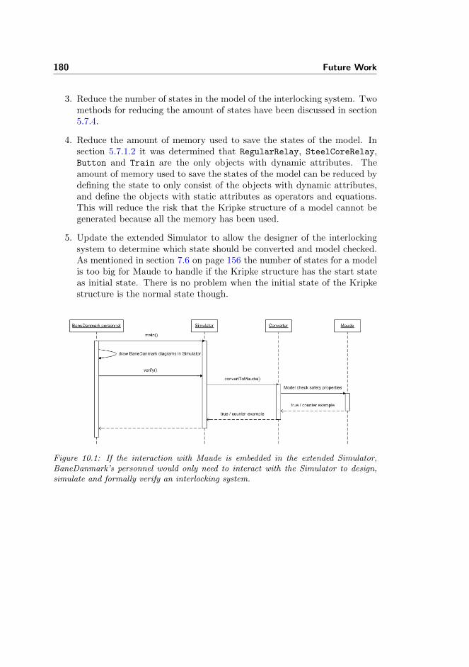
180 Future Work
3. Reduce the number of states in the model of the interlocking system. Twomethods for reducing the amount of states have been discussed in section5.7.4.
4. Reduce the amount of memory used to save the states of the model. Insection 5.7.1.2 it was determined that RegularRelay, SteelCoreRelay,Button and Train are the only objects with dynamic attributes. Theamount of memory used to save the states of the model can be reduced bydefining the state to only consist of the objects with dynamic attributes,and define the objects with static attributes as operators and equations.This will reduce the risk that the Kripke structure of a model cannot begenerated because all the memory has been used.
5. Update the extended Simulator to allow the designer of the interlockingsystem to determine which state should be converted and model checked.As mentioned in section 7.6 on page 156 the number of states for a modelis too big for Maude to handle if the Kripke structure has the start stateas initial state. There is no problem when the initial state of the Kripkestructure is the normal state though.
Figure 10.1: If the interaction with Maude is embedded in the extended Simulator,BaneDanmark’s personnel would only need to interact with the Simulator to design,simulate and formally verify an interlocking system.

Chapter 11
Conclusion
The goal of this project has been achieved, as a method has been developed forhow safety properties are derived from a given interlocking system, and how itcan be verified whether the derived safety properties hold.
In addition to the overall goal of this project we decided that a model of relayinterlocking systems should be specified such that the safety properties can begenerically derived from the model. Different modelling languages were consid-ered for the purpose of modelling an interlocking system, whereafter the spec-ification language Maude was selected. A model of an interlocking system hassuccessfully been specified in Maude and models how trains of different lengthsdrive on a station, how operators use buttons to switch points and lock trainroutes and finally how the circuit responds the these actions.
Besides the train route table safety properties that have been derived from agiven model, general safety properties defining that collisions and derailings mustnever happen have been formalised as well. All safety properties are formalisedas LTL formulae which makes it possible to use the Maude model checker toverify the model.
The model has successfully been tested thoroughly on different test interlockingsystems. Furthermore the method for verifying a model in relation to safetyproperties was applied to a model of the interlocking system of Stenstrup station.

182 Conclusion
It turned out that the number of states of this model was too big to produceresults for the entire model. After having searched approximately 41.000 statesMaude ran out of memory. For these states, it has been verified that there areno collisions and no derailings at Stenstrup station. Furthermore, the modelhas been verified in relation to a confidence condition and a train route tablesafety property. When modifying the Stenstrup interlocking system by removingcomponents from the station, the verification process showed that collisions andderailings occurred and that the model did not satisfy the train route tablesafety property.
BaneDanmark requests that all internal events (dropping and drawing of relays)are confluent. A method for testing whether the internal transitions of a modelof an interlocking system are confluent has been developed and tested for a stateon the model of Stenstrup station.
Finally, some auxiliary tools have been developed with two purposes in mind.One is to ease the testing of the Maude specification. Another and more inter-esting purpose is to make it possible to specify a model of a given interlockingsystem in Maude without having any knowledge about Maude.
When we were to decide on the specification language to use, we did not havemuch insight into the strengths and weaknesses of Maude, but during the projectperiod we have gotten much more experienced in how Maude should be used,what to avoid and what to aim for when specifying a model. Having had thisknowledge when starting the project, we might have designed the model inanother way. However, it has been very interesting to get acquainted with anew specification language and we have learned a lot by having to teach ourselfhow to use this language throughout the project period.

Appendix A
Terms
This section is in general based on [3] and our own definitions of terms in thedomain.
Bi-simulation Bi-simulation is a binary equivalence relation between statetransition systems. Bi-simulation is used to determine whether two sys-tems behave in the same way even though the systems are not identical.
Church-Rosser A term rewriting system is Church-Rosser if it is confluentand sort-decreasing, see section 3.2.1.
Component Component is a common term in the domain of interlocking sys-tems for electrical components, track sections and signals.
Computational tree logic CTL is a branching time temporal logic which rea-sons about time in branching models.
Confluence A set of equations E is confluent when any two rewritings can beunified by further rewriting, i.e. the set is confluent if any two rewritingswill always result in the same rewriting. For a thorough definition and anexample see section 3.2.1.2.
CTL see computational tree logic.

184 Terms
Diagram ”Diagram” refers to the BaneDanmark documentation of the circuitof an interlocking system. A circuit diagram documents the electricalcomponents of a circuit and how they are connected with wires.
Electrical component Electrical component is a common term in the domainof interlocking systems for components that can be conducting, i.e. relays(regular- and steel core relays), contacts, buttons, lamps, fuses, resistorsand track sections.
External events External events are actions that taken can happen externallyto an interlocking system circuit, i.e. a train occupying/freeing a tracksection or an operator pushing/releasing a button.
General safety properties The term “general safety properties” refers to theto safety properties of any railway system i.e. that it must never be thecase that there are collisions and derailings.
Idle An interlocking system can be idle or not idle as defined by [1]. An inter-locking system is idle when no more relays can drop or draw.
Initial state An initial state is meant as a relative description of a state in aKripke structure. Which state the initial state is depends on the Kripkestructure being explained but typically the initial state is the state thathas no inbound transitions. The initial state of a model for an interlockingsystem can be either the start or normal state depending on whether theconfiguration given to the Maude system describes the start or normalstate.
Interlocking system Interlocking systems are the domain of the project. Theterm “interlocking system” is a common term for the circuit and tracklayout. See chapter 2 or [5, 1] for a more detailed description.
Kripke structure A Kripke structure is a non-deterministic finite state ma-chine formally defined as a four-tuple M = (S, I,R, L), see section 3.2.2.1.
Linear Temporal Logic LTL is a logic which reasons about time in linearmodels, see section 3.2.2.2.
Linear Track Section A linear track section is a non-branching track sectionas opposed to a point.
LTL See linear temporal logic.
Model The term “model” refers to all the modules in Maude that specifies thebehaviour of an interlocking system, i.e. the circuit, track layout, train andthe train route table. Furthermore the model includes the specification ofthe initial state of a given interlocking system. Figure 5.8 on page 81depicts what the term “model” covers.

185
Normal state The normal state is a state after a number of transitions fromthe start state of an interlocking system. The normal state is the statewhere the interlocking system is idle and no external transitions have takenplace yet.
Object state Each object has a number of object states, i.e. possible valueassignments depending on the type and number of attributes of the object.Assume an object A has n attributes {a1, a2, · · · , an} where each attributehas vi possible value assignments, i.e. attribute a1 has v1 possible valueassignments etc. In this case the object A has v1 · v2 · · · · · vn object states.
Point A point is a branching track section as opposed to a linear track section.
Rewrite theory A rewrite theory in Maude is specified by a system module.The rewrite theory thus consists of sorts, kinds, operators and three kindsof arguments; equations, memberships and rules.
Relay interlocking system See interlocking system.
Safety question The safety question is the question of whether the generalsafety properties as well as the train route table safety properties hold fora given station.
Sort-decreasing Sorts are sort-decreasing if the sort declarations not are cyclic,see section 3.2.1.3.
Start state The start state of an interlocking system is the state where thepower has not yet been switched on. When the power has been switchedon and all internal events have changed state the interlocking system is inthe normal state.
Track Section ”Track section” is the common term for linear track sectionsand points in relation to a track layout in an interlocking system.
Train route table safety properties In a relay interlocking system a trainroute table implicitly defines a number of safety properties. It is desiredby BaneDanmark that these safety properties hold for the interlockingsystem, and that if the train route table properties hold it implies thatthe general safety properties hold as well. Whether it is actually the casethat if the train route table safety properties hold then the general safetyproperties hold is unknown. By verifying a given interlocking system thisquestion can be answered for the given station.
Valid States in which a collision or a derailing has occurred are consideredinvalid states, as well as all states after a collision or a derailing.

186 Terms

Appendix B
How to use Maude
Maude is free software for Linux, MacOS X and Windows and can easily bedownloaded from the official web page: http://maude.cs.uiuc.edu. This webpage includes simple installation instructions and further documentation on howto use Maude. Additionally, the Maude team provides a number of Maudeapplications and supplementary tools for Maude specifications.
B.1 Installing Maude on Unix
Even though Maude runs on Windows as well, Maude is primarily made forUnix. The performance on Unix is also much better than on Windows. For thisreason we will focus on how to get Maude installed on Unix:
1. Download the maude.tar.gz file from the Maude homepagehttp://maude.cs.uiuc.edu.
2. Open a shell, navigate to the folder with the maude.tar.gz file.
3. Issue the following commands:gunzip maude.tar.gz
tar -xvf maude.tar

188 How to use Maude
4. A maude directory is generated containing a number of files, includingmaude.linux, maude.linux64, model-checker.maude and prelude.maude.The former two files are the executables, which allows you to start upMaude.
B.2 Interacting with Maude
When Maude is installed it can be run as a command line program as seen infigure B.1. At this stage the user can either type in the specification directly inMaude or load pre-written modules.
Figure B.1: This is how Maude looks when it is launched and ready to load modulesetc.
Maude provides a large number of predefined modules. If one wants to overwritethese modules or add new ones it can either be done by typing them directly intoMaude’s command line or by loading them from a file. If modules are defined bytyping them into the command line the first line has to start with mod 〈Name〉is, where 〈Name〉 is the name of the module, and the last line has to end withendm for Maude to read the input as a module.
Alternatively, if the modules are defined in files, firstly navigate to the specificfolder using standard Unix commands (like cd, cd .., pwd, etc.) and thensecondly type either“in 〈File〉”or“load 〈File〉”where 〈File〉 is the name of thefile. The only difference between these commands is whether certain comments(lines starting with --> or ***>) are written to the console. The first commandprints the comments whereas the second command suppresses the comments.

Appendix C
Module structure
Figure C.1 shows the inclusion relationship between the Maude modules spec-ifying the model of an interlocking system. A more abstract description ofthe overall inclusion relationship can be seen in figure 5.8 on page 81. Thedashed squares Circuit, Track Layout, Train and Train Route Table in figure5.8 on page 81 corresponds to the modules CIRCUIT, TRACK-LAYOUT, TRAIN andTRAIN-ROUTE-TABLE and all the modules they include respectively in figure C.1.

190 Module structure
Figure C.1: The inclusion relationship of the modules used in the interlocking systemmodel. An arrow from A to B means that module A includes module B. The mod-ules CIRCUIT, TRACK-LAYOUT, TRAIN and TRAIN-ROUTE-TABLE and all the modules theyinclude respectively correspond to the dashed rectangles in figure 5.8.

Appendix D
Maude Built-In Modules
In this section the Maude built-in modules which are used by the model devel-oped in this project will be listed.
D.1 CONFIGURATION
The CONFIGURATION module is used to define objects of an interlocking systemas well as states in the corresponding Kripke structure:
mod CONFIGURATION is
sorts Attribute AttributeSet .
sorts Oid Cid Object Msg Portal Configuration .
subsorts Attribute < AttributeSet .
subsorts Object Msg Portal < Configuration .
op none : -> AttributeSet [ctor] .
op _‘,_ : AttributeSet AttributeSet -> AttributeSet [
assoc comm id: none ctor] .
op <_:_|_> : Oid Cid AttributeSet -> Object [obj ctor] .
op none : -> Configuration [ctor] .
op __ : Configuration Configuration -> Configuration [
assoc comm config id: none ctor] .
op <> : -> Portal [ctor] .

192 Maude Built-In Modules
endm
D.2 QID
The QID module is used to define the IDs of the objects:
fmod QID is
protecting STRING .
sorts Qid .
op <Qids > : -> Qid [special (
id-hook QuotedIdentifierSymbol ())] .
op string : Qid -> String [special (
id-hook QuotedIdentifierOpSymbol (string)
op-hook quotedIdentifierSymbol (<Qids > : ~> Qid)
op-hook stringSymbol (<Strings > : ~> String))] .
op qid : [String] -> [Qid] [special (
id-hook QuotedIdentifierOpSymbol (qid)
op-hook quotedIdentifierSymbol (<Qids > : ~> Qid)
op-hook stringSymbol (<Strings > : ~> String))] .
endfm
D.3 NAT
The NAT module defines a natural number which is used e.g. when defining thelength of trains or track sections.
fmod NAT is
protecting BOOL .
sorts Zero NzNat Nat .
subsorts Zero NzNat < Nat .
op 0 : -> Zero [ctor] .
op s_ : Nat -> NzNat [iter ctor special (
id-hook SuccSymbol ()
term -hook zeroTerm (0))] .
op _+_ : NzNat Nat -> NzNat [assoc comm prec 33 special (
id-hook ACU_NumberOpSymbol (+)
op-hook succSymbol (s_ : Nat ~> NzNat))] .
op _+_ : Nat Nat -> Nat [ditto] .
op sd : Nat Nat -> Nat [comm special (
id-hook CUI_NumberOpSymbol (sd)
op-hook succSymbol (s_ : Nat ~> NzNat))] .

D.3 NAT 193
op _*_ : NzNat NzNat -> NzNat [assoc comm prec 31 special
(
id-hook ACU_NumberOpSymbol (*)
op-hook succSymbol (s_ : Nat ~> NzNat))] .
op _*_ : Nat Nat -> Nat [ditto] .
op _quo_ : Nat NzNat -> Nat [prec 31 gather (E e) special
(
id-hook NumberOpSymbol (quo)
op-hook succSymbol (s_ : Nat ~> NzNat))] .
op _rem_ : Nat NzNat -> Nat [prec 31 gather (E e) special
(
id-hook NumberOpSymbol (rem)
op-hook succSymbol (s_ : Nat ~> NzNat))] .
op _^_ : Nat Nat -> Nat [prec 29 gather (E e) special (
id-hook NumberOpSymbol (^)
op-hook succSymbol (s_ : Nat ~> NzNat))] .
op _^_ : NzNat Nat -> NzNat [ditto] .
op modExp : [Nat] [Nat] [NzNat] -> [Nat] [special (
id-hook NumberOpSymbol (modExp)
op-hook succSymbol (s_ : Nat ~> NzNat))] .
op gcd : NzNat Nat -> NzNat [assoc comm special (
id-hook ACU_NumberOpSymbol (gcd)
op-hook succSymbol (s_ : Nat ~> NzNat))] .
op gcd : Nat Nat -> Nat [ditto] .
op lcm : NzNat NzNat -> NzNat [assoc comm special (
id-hook ACU_NumberOpSymbol (lcm)
op-hook succSymbol (s_ : Nat ~> NzNat))] .
op lcm : Nat Nat -> Nat [ditto] .
op min : NzNat NzNat -> NzNat [assoc comm special (
id-hook ACU_NumberOpSymbol (min)
op-hook succSymbol (s_ : Nat ~> NzNat))] .
op min : Nat Nat -> Nat [ditto] .
op max : NzNat Nat -> NzNat [assoc comm special (
id-hook ACU_NumberOpSymbol (max)
op-hook succSymbol (s_ : Nat ~> NzNat))] .
op max : Nat Nat -> Nat [ditto] .
op _xor_ : Nat Nat -> Nat [assoc comm prec 55 special (
id-hook ACU_NumberOpSymbol (xor)
op-hook succSymbol (s_ : Nat ~> NzNat))] .
op _&_ : Nat Nat -> Nat [assoc comm prec 53 special (
id-hook ACU_NumberOpSymbol (&)
op-hook succSymbol (s_ : Nat ~> NzNat))] .
op _|_ : NzNat Nat -> NzNat [assoc comm prec 57 special (
id-hook ACU_NumberOpSymbol (|)
op-hook succSymbol (s_ : Nat ~> NzNat))] .
op _|_ : Nat Nat -> Nat [ditto] .
op _>>_ : Nat Nat -> Nat [prec 35 gather (E e) special (

194 Maude Built-In Modules
id-hook NumberOpSymbol (>>)
op-hook succSymbol (s_ : Nat ~> NzNat))] .
op _<<_ : Nat Nat -> Nat [prec 35 gather (E e) special (
id-hook NumberOpSymbol (<<)
op-hook succSymbol (s_ : Nat ~> NzNat))] .
op _<_ : Nat Nat -> Bool [prec 37 special (
id-hook NumberOpSymbol (<)
op-hook succSymbol (s_ : Nat ~> NzNat)
term -hook trueTerm (true)
term -hook falseTerm (false))] .
op _<=_ : Nat Nat -> Bool [prec 37 special (
id-hook NumberOpSymbol (<=)
op-hook succSymbol (s_ : Nat ~> NzNat)
term -hook trueTerm (true)
term -hook falseTerm (false))] .
op _>_ : Nat Nat -> Bool [prec 37 special (
id-hook NumberOpSymbol (>)
op-hook succSymbol (s_ : Nat ~> NzNat)
term -hook trueTerm (true)
term -hook falseTerm (false))] .
op _>=_ : Nat Nat -> Bool [prec 37 special (
id-hook NumberOpSymbol (>=)
op-hook succSymbol (s_ : Nat ~> NzNat)
term -hook trueTerm (true)
term -hook falseTerm (false))] .
op _divides_ : NzNat Nat -> Bool [prec 51 special (
id-hook NumberOpSymbol (divides)
op-hook succSymbol (s_ : Nat ~> NzNat)
term -hook trueTerm (true)
term -hook falseTerm (false))] .
endfm
D.4 BOOL
The BOOL module is used to define and evaluate boolean expressions:
fmod BOOL is
protecting TRUTH .
op _and_ : Bool Bool -> Bool [assoc comm prec 55] .
op _or_ : Bool Bool -> Bool [assoc comm prec 59] .
op _xor_ : Bool Bool -> Bool [assoc comm prec 57] .
op not_ : Bool -> Bool [prec 53] .
op _implies_ : Bool Bool -> Bool [prec 61 gather (e E)] .
vars A B C : Bool .

D.5 EXT-BOOL 195
eq true and A = A .
eq false and A = false .
eq A and A = A .
eq false xor A = A .
eq A xor A = false .
eq A and (B xor C) = A and B xor A and C .
eq not A = A xor true .
eq A or B = A and B xor A xor B .
eq A implies B = not (A xor A and B) .
endfm
D.5 EXT-BOOL
The EXT-BOOL module is used to enforce lazy evaluation of boolean expressionsin order to optimise the performance of the Maude model as mentioned in section5.8.1:
fmod EXT -BOOL is
protecting BOOL .
op _and -then_ : Bool Bool -> Bool [strat (1 0) prec 55
gather (e E)] .
op _or -else_ : Bool Bool -> Bool [strat (1 0) prec 59
gather (e E)] .
var B : [Bool] .
eq true and -then B = B .
eq false and -then B = false .
eq true or-else B = true .
eq false or-else B = B .
endfm
D.6 MODEL-CHECKER
The MODEL-CHECKER module is used when model checking LTL formulae in aKripke structure of an interlocking system:
fmod MODEL -CHECKER is
protecting QID .
including SATISFACTION .
including LTL .
sorts RuleName Transition TransitionList ModelCheckResult
.

196 Maude Built-In Modules
subsorts Prop < Formula .
subsorts Qid < RuleName .
subsorts Transition < TransitionList .
subsorts Bool < ModelCheckResult .
ops unlabeled deadlock : -> RuleName .
op ‘{_‘,_‘} : State RuleName -> Transition [ctor] .
op nil : -> TransitionList [ctor] .
op __ : TransitionList TransitionList -> TransitionList [
assoc id: nil ctor] .
op counterexample : TransitionList TransitionList ->
ModelCheckResult [ctor] .
op modelCheck : [State] [Formula] -> [ModelCheckResult] [
special (
id-hook ModelCheckerSymbol ()
op-hook trueSymbol (True : ~> Formula)
op-hook falseSymbol (False : ~> Formula)
op-hook notSymbol (~_ : Formula ~> Formula)
op-hook nextSymbol (O_ : Formula ~> Formula)
op-hook andSymbol (_/\_ : Formula Formula ~> Formula)
op-hook orSymbol (_\/_ : Formula Formula ~> Formula)
op-hook untilSymbol (_U_ : Formula Formula ~> Formula)
op-hook releaseSymbol (_R_ : Formula Formula ~>
Formula)
op-hook satisfiesSymbol (_|=_ : State Formula ~> Bool)
op-hook qidSymbol (<Qids > : ~> Qid)
op-hook unlabeledSymbol (unlabeled : ~> RuleName)
op-hook deadlockSymbol (deadlock : ~> RuleName)
op-hook transitionSymbol ({_, _} : State RuleName ~>
Transition)
op-hook transitionListSymbol (__ : TransitionList
TransitionList ~> TransitionList)
op-hook nilTransitionListSymbol (nil : ~>
TransitionList)
op-hook counterexampleSymbol (counterexample :
TransitionList TransitionList ~> ModelCheckResult)
term -hook trueTerm (true))] .
endfm
D.7 LTL
The LTL module is used when defining LTL formulae to be model checked in aKripke structure of an interlocking system:
fmod LTL is

D.7 LTL 197
protecting BOOL .
sorts Formula .
ops True False : -> Formula [ctor format (g o)] .
op ~_ : Formula -> Formula [ctor prec 53 format (r o d)]
.
op _/\_ : Formula Formula -> Formula [comm ctor prec 55
gather (E e) format (d r o d)] .
op _\/_ : Formula Formula -> Formula [comm ctor prec 59
gather (E e) format (d r o d)] .
op O_ : Formula -> Formula [ctor prec 53 format (r o d)]
.
op _U_ : Formula Formula -> Formula [ctor prec 63 format
(d r o d)] .
op _R_ : Formula Formula -> Formula [ctor prec 63 format
(d r o d)] .
op _->_ : Formula Formula -> Formula [prec 65 gather (e E
) format (d r o d)] .
op _<->_ : Formula Formula -> Formula [prec 65 format (d
r o d)] .
op <>_ : Formula -> Formula [prec 53 format (r o d)] .
op ‘[‘]_ : Formula -> Formula [prec 53 format (r d o d)]
.
op _W_ : Formula Formula -> Formula [prec 63 format (d r
o d)] .
op _|->_ : Formula Formula -> Formula [prec 63 format (d
r o d)] .
op _=>_ : Formula Formula -> Formula [prec 65 gather (e E
) format (d r o d)] .
op _<=>_ : Formula Formula -> Formula [prec 65 format (d
r o d)] .
vars f g : Formula .
eq f -> g = ~ f \/ g .
eq f <-> g = (f -> g) /\ (g -> f) .
eq <> f = True U f .
eq [] f = False R f .
eq f W g = (f U g) \/ [] f .
eq f |-> g = [] (f -> (<> g)) .
eq f => g = [] (f -> g) .
eq f <=> g = [] (f <-> g) .
eq ~ True = False .
eq ~ False = True .
eq ~ ~ f = f .
eq ~ (f \/ g) = ~ f /\ ~ g .
eq ~ (f /\ g) = ~ f \/ ~ g .
eq ~ O f = O ~ f .
eq ~ (f U g) = (~ f) R (~ g) .
eq ~ (f R g) = (~ f) U (~ g) .

198 Maude Built-In Modules
endfm
D.8 LTL-SIMPLIFIER
The LTL-SIMPLIFIER module is an extension of the LTL module which providesequations for simplifying LTL formulae:
fmod LTL -SIMPLIFIER is
including LTL .
sorts TrueFormula FalseFormula PureFormula PE-Formula PU-
Formula .
subsorts TrueFormula FalseFormula < PureFormula < PE-
Formula PU-Formula < Formula .
op True : -> TrueFormula [ctor ditto] .
op False : -> FalseFormula [ctor ditto] .
op _/\_ : PE-Formula PE-Formula -> PE-Formula [ctor ditto
] .
op _/\_ : PU-Formula PU-Formula -> PU-Formula [ctor ditto
] .
op _/\_ : PureFormula PureFormula -> PureFormula [ctor
ditto] .
op _\/_ : PE-Formula PE-Formula -> PE-Formula [ctor ditto
] .
op _\/_ : PU-Formula PU-Formula -> PU-Formula [ctor ditto
] .
op _\/_ : PureFormula PureFormula -> PureFormula [ctor
ditto] .
op O_ : PE-Formula -> PE-Formula [ctor ditto] .
op O_ : PU-Formula -> PU-Formula [ctor ditto] .
op O_ : PureFormula -> PureFormula [ctor ditto] .
op _U_ : PE-Formula PE-Formula -> PE-Formula [ctor ditto]
.
op _U_ : PU-Formula PU-Formula -> PU-Formula [ctor ditto]
.
op _U_ : PureFormula PureFormula -> PureFormula [ctor
ditto] .
op _U_ : TrueFormula Formula -> PE-Formula [ctor ditto] .
op _U_ : TrueFormula PU-Formula -> PureFormula [ctor
ditto] .
op _R_ : PE-Formula PE-Formula -> PE-Formula [ctor ditto]
.
op _R_ : PU-Formula PU-Formula -> PU-Formula [ctor ditto]
.
op _R_ : PureFormula PureFormula -> PureFormula [ctor
ditto] .

D.8 LTL-SIMPLIFIER 199
op _R_ : FalseFormula Formula -> PU-Formula [ctor ditto]
.
op _R_ : FalseFormula PE-Formula -> PureFormula [ctor
ditto] .
vars p q r s : Formula .
var pe : PE-Formula .
var pu : PU-Formula .
var pr : PureFormula .
op _<=_ : Formula Formula -> Bool [prec 75] .
eq (p U r) /\ (q U r) = (p /\ q) U r .
eq (p R r) \/ (q R r) = (p \/ q) R r .
eq (p U q) \/ (p U r) = p U (q \/ r) .
eq (p R q) /\ (p R r) = p R (q /\ r) .
eq True U (p U q) = True U q .
eq False R (p R q) = False R q .
eq p U pe = pe .
eq p R pu = pu .
eq O pr = pr .
eq O p /\ O q = O (p /\ q) .
eq O p \/ O q = O (p \/ q) .
eq O p U O q = O (p U q) .
eq O p R O q = O (p R q) .
eq True U O p = O (True U p) .
eq False R O p = O (False R p) .
eq (False R (True U p)) \/ (False R (True U q)) = False R
(True U (p \/ q)) .
eq (True U (False R p)) /\ (True U (False R q)) = True U
(False R (p /\ q)) .
eq p <= p = true .
eq False <= p = true .
eq p <= True = true .
ceq p <= (q /\ r) = true if (p <= q) /\ (p <= r) .
ceq p <= (q \/ r) = true if p <= q .
ceq (p /\ q) <= r = true if p <= r .
ceq (p \/ q) <= r = true if (p <= r) /\ (q <= r) .
ceq p <= (q U r) = true if p <= r .
ceq (p R q) <= r = true if q <= r .
ceq (p U q) <= r = true if (p <= r) /\ (q <= r) .
ceq p <= (q R r) = true if (p <= q) /\ (p <= r) .
ceq (p U q) <= (r U s) = true if (p <= r) /\ (q <= s) .
ceq (p R q) <= (r R s) = true if (p <= r) /\ (q <= s) .
ceq p /\ q = p if p <= q .
ceq p \/ q = q if p <= q .
ceq p /\ q = False if p <= ~ q .
ceq p \/ q = True if ~ p <= q .
ceq p U q = q if p <= q .
ceq p R q = q if q <= p .

200 Maude Built-In Modules
ceq p U q = True U q if p =/= True /\ ~ q <= p .
ceq p R q = False R q if p =/= False /\ q <= ~ p .
ceq p U (q U r) = q U r if p <= q .
ceq p R (q R r) = q R r if q <= p .
endfm
D.9 SATISFACTION
The SATISFACTION module is used when defining predicates for the Kripke struc-ture of an interlocking system:
fmod SATISFACTION is
protecting BOOL .
sorts State Prop .
op _|=_ : State Prop -> Bool [frozen (1 2)] .
endfm

Appendix E
Model and VerificationMaude Modules
The following sections will list the Maude modules which have been specifiedfor modelling and verifying an interlocking system.
E.1 Model
This section provides the most important Maude modules developed in thisproject. The following sections will list the specified Maude modules alphabet-ically for each of the main areas of the model i.e. the circuit, the track layout,the train and the train route table.
E.1.1 Circuit Modules
This section contains all the Maude modules specified for the circuit of an in-terlocking system.

202 Model and Verification Maude Modules
E.1.1.1 BUTTON
mod BUTTON is
pr ELECTRICAL -COMPONENT .
sort Button .
subsort Button < ElectricalComponent .
op Button : -> Button [ctor] .
op pushed :_ : Bool -> Attribute [ctor gather (&)] .
var A : Bool .
var B : Qid .
eq wfObject(< B : Button | pushed : A >) = true .
endm
E.1.1.2 CIRCUIT
mod CIRCUIT is
pr FUSE .
pr LAMP .
pr RESISTOR .
pr BUTTON .
pr CONTACT .
pr REGULAR -RELAY .
pr STEEL -CORE -RELAY .
vars B R : Qid .
var V@Relay : Relay .
var ATTS : AttributeSet .
var CONF : Configuration .
*** ******************************************
*** Button behaviour
*** ******************************************
crl [pushButton] :
{ < B : Button | pushed : false > CONF }
=>
{ < B : Button | pushed : true > CONF }
if
idle(< B : Button | pushed : false > CONF)
and -then
valid(< B : Button | pushed : false > CONF) .
crl [releaseButton] :

E.1 Model 203
{ < B : Button | pushed : true > CONF }
=>
{ < B : Button | pushed : false > CONF }
if
idle(< B : Button | pushed : true > CONF)
and -then
valid(< B : Button | pushed : true > CONF) .
*** ******************************************
*** Relay behaviour
*** ******************************************
crl [drawRelay] :
{ < R : V@Relay | drawn : false , ATTS > CONF }
=>
{ < R : V@Relay | drawn : true , ATTS > CONF }
if
valid(< R : V@Relay | drawn : false , ATTS > CONF)
and -then
canDraw(R, (< R : V@Relay | drawn : false , ATTS >
CONF)) .
crl [dropRelay] :
{ < R : V@Relay | drawn : true , ATTS > CONF }
=>
{ < R : V@Relay | drawn : false , ATTS > CONF }
if
valid(< R : V@Relay | drawn : true , ATTS > CONF)
and -then
canDrop(R, (< R : V@Relay | drawn : true , ATTS >
CONF)) .
endm
E.1.1.3 CONTACT
mod CONTACT is
pr RELAY .
sort Contact .
subsort Contact < ElectricalComponent .
op Contact : -> Contact [ctor] .
var B : Bool .
vars C R : Qid .

204 Model and Verification Maude Modules
eq wfObject(< C : Contact | relay : R, upper : B >) =
true .
endm
E.1.1.4 ELECTRICAL-COMPONENT
mod ELECTRICAL -COMPONENT is
pr COMMON .
pr QID -SET .
sort ElectricalComponent .
subsort ElectricalComponent < Cid .
var C : Qid .
var CS : QidSet .
var Conf : Configuration .
*** ******************************************
--- Checks whether all electrical components
--- associated with the ids in QidSet
--- are conducting.
---
--- Qid:
--- The id of the component to check.
--- Configuration:
--- The configurations to look up in.
--- -> Bool:
--- True if the component is conducting;
--- alse otherwise.
*** ******************************************
op conducting : Qid Configuration -> Bool .
eq conducting(C, Conf) = false [owise] .
op anyConducting : QidSet Configuration -> Bool .
eq anyConducting ((C, CS), Conf) = conducting(C, Conf) or-
else anyConducting(CS, Conf) .
eq anyConducting(empty , Conf) = false .
endm
E.1.1.5 FUSE
mod FUSE is
pr ELECTRICAL -COMPONENT .
sort Fuse .
subsort Fuse < ElectricalComponent .

E.1 Model 205
op Fuse : -> Fuse [ctor] .
var F : Qid .
eq wfObject(< F : Fuse | none >) = true .
endm
E.1.1.6 LAMP
mod LAMP is
pr ELECTRICAL -COMPONENT .
sorts Lamp Color .
subsort Lamp < ElectricalComponent .
op Lamp : -> Lamp [ctor] .
op color :_ : Color -> Attribute [ctor gather (&)] .
op green : -> Color .
op yellow : -> Color .
op red : -> Color .
vars L P : Qid .
var Cs Ls : QidSet .
var ATTS@0 : AttributeSet .
var C : Color .
var Conf : Configuration .
eq wfObject(< L : Lamp | color : C >) = true .
op shines : QidSet Configuration -> Bool .
ceq shines ((L, Ls), Conf) = shines(L, Conf) or-else
shines(Ls, Conf) if Ls =/= empty .
eq shines(L, Conf) = conducting(L, Conf) .
eq shines(empty , Conf) = false .
endm
E.1.1.7 REGULAR-RELAY
mod REGULAR -RELAY is
pr RELAY .
sort RegularRelay .
subsort RegularRelay < Relay .

206 Model and Verification Maude Modules
op RegularRelay : -> RegularRelay [ctor] .
var B : Bool .
var R : Qid .
var CONF : Configuration .
eq canDraw(R, (< R : RegularRelay | drawn : false > CONF)
) =
conducting(R, (< R : RegularRelay | drawn : false >
CONF)) .
eq canDrop(R, (< R : RegularRelay | drawn : true > CONF))
=
not conducting(R, (< R : RegularRelay | drawn : true >
CONF)) .
eq wfObject(< R : RegularRelay | drawn : B >) = true .
endm
E.1.1.8 RELAY
mod RELAY is
pr ELECTRICAL -COMPONENT .
sort Relay .
subsort Relay < ElectricalComponent .
op Relay : -> Relay [ctor] .
op drawn :_ : Bool -> Attribute [ctor gather (&)] .
var B : Bool .
var R : Qid .
var V@Relay : Relay .
var ATTS : AttributeSet .
var CONF : Configuration .
ops canDraw canDrop : Qid Configuration -> Bool [memo] .
eq canDraw(R, CONF) = false [owise] .
eq canDrop(R, CONF) = false [owise] .
ceq idle(< R : V@Relay | drawn : false , ATTS > CONF) =
false
if canDraw(R, (< R : V@Relay | drawn : false , ATTS > CONF
)) .
ceq idle(< R : V@Relay | drawn : true , ATTS > CONF) =
false

E.1 Model 207
if canDrop(R, (< R : V@Relay | drawn : true , ATTS > CONF)
) .
op isDrawn : Qid Configuration -> Bool .
eq isDrawn(R, < R : V@Relay | drawn : B > CONF) = B .
endm
E.1.1.9 RESISTOR
mod RESISTOR is
pr ELECTRICAL -COMPONENT .
sort Resistor .
subsort Resistor < ElectricalComponent .
op Resistor : -> Resistor [ctor] .
var R : Qid .
eq wfObject(< R : Resistor | none >) = true .
endm
E.1.1.10 STEEL-CORE-RELAY
mod STEEL -CORE -RELAY is
pr RELAY .
sort SteelCoreRelay .
subsort SteelCoreRelay < Relay .
op SteelCoreRelay : -> SteelCoreRelay [ctor] .
op droppingComponent :_ : Qid -> Attribute [ctor gather
(&)] .
op drawingComponents :_ : QidSet -> Attribute [ctor
gather (e)] .
var B : Bool .
vars C S : Qid .
var Cs : QidSet .
var ATTS : AttributeSet .
var CONF : Configuration .
eq canDraw(S, (< S : SteelCoreRelay | drawn : false ,
drawingComponents : Cs, ATTS > CONF)) =
conducting(S, (< S : SteelCoreRelay | drawn : false ,
drawingComponents : Cs, ATTS > CONF))

208 Model and Verification Maude Modules
and -then
anyConducting(Cs, (< S : SteelCoreRelay | drawn :
false , drawingComponents : Cs, ATTS > CONF)) .
eq canDrop(S, (< S : SteelCoreRelay | drawn : true ,
droppingComponent : C, ATTS > CONF)) =
conducting(S, (< S : SteelCoreRelay | drawn : true ,
droppingComponent : C, ATTS > CONF))
and -then
conducting(C, (< S : SteelCoreRelay | drawn : true ,
droppingComponent : C, ATTS > CONF)) .
op isSteelCoreRelay : Qid Configuration -> Bool .
eq isSteelCoreRelay(S, (< S : SteelCoreRelay | ATTS >
CONF )) = true .
eq isSteelCoreRelay(S, CONF) = false [owise] .
eq wfObject(< S : SteelCoreRelay | drawn : B,
droppingComponent : C, drawingComponents : Cs >) =
true .
endm

E.1 Model 209
E.1.2 Track Layout Modules
This subsection contains all the Maude modules specified for the track layoutof an interlocking system.
E.1.2.1 LINEAR-TRACK-SECTION
mod LINEAR -TRACK -SECTION is
pr TRACK -SECTION .
sort LinearTrackSection .
subsort LinearTrackSection < TrackSection .
op LinearTrackSection : -> LinearTrackSection [ctor] .
op platform :_ : Bool -> Attribute [ctor gather (&)] .
var B : Bool .
vars R S1 S2 TS TSN1 TSN2 : Qid .
var L : Nat .
var T : Qid .
eq wfObject(< TS : LinearTrackSection | relay : R,
platform : B, length : L, neighbour1 : TSN1 ,
neighbour2 : TSN2 , signal1 : S1, signal2 : S2 >) =
true .
endm
E.1.2.2 NAT-SET
mod NAT -SET is
protecting SET{Nat} * (sort NeSet{Nat} to NeNatSet , sort
Set{Nat} to NatSet) .
endm
E.1.2.3 POINT
mod POINT is
pr TRACK -SECTION .
sort Point .
sort Position .
subsort Point < TrackSection .
op Point : -> Point [ctor] .

210 Model and Verification Maude Modules
*** neighbour1 -> stem
*** neighbour2 -> plus
*** neighbour3 -> minus
op neighbour3 :_ : Qid -> Attribute [ctor gather (&)] .
op relay+ :_ : Qid -> Attribute [ctor gather (&)] .
op relay - :_ : Qid -> Attribute [ctor gather (&)] .
*** signal1 -> stem
*** signal2 -> plus
*** signal3 -> minus
op signal3 :_ : Qid -> Attribute [ctor gather (&)] .
op intermediate : -> Position .
op plus : -> Position .
op minus : -> Position .
vars P TSN1 TSN2 TSN3 S1 S2 S3 R+ R- R : Qid .
var N : Nat .
vars ATTS : AttributeSet .
op wfPointAtts : AttributeSet -> Bool .
eq wfPointAtts(relay : R, relay+ : R+, relay - : R-,
length : N) = true .
eq wfPointAtts(ATTS) = false [owise] .
ceq wfObject(< P : Point | neighbour1 : TSN1 , neighbour2
: TSN2 , neighbour3 : TSN3 , signal1 : S1 , signal2 : S2,
signal3 : S3, ATTS >) = true if wfPointAtts(ATTS) .
endm
E.1.2.4 SIGNAL
mod SIGNAL is
pr CIRCUIT .
sort Signal .
subsort Signal < Cid .
op Signal : -> Signal [ctor] .
op lamps :_ : QidSet -> Attribute [ctor gather (e)] .
op noSignal : -> Qid .
vars S L1 L2 : Qid .
vars Ls : QidSet .
var C : Color .
var CONF : Configuration .
eq wfObject(< S : Signal | lamps : Ls >) = true .

E.1 Model 211
op noGreenLamps : QidSet Configuration -> Bool .
eq noGreenLamps ((L1, Ls), CONF) = noGreenLamps(L1, CONF)
and -then noGreenLamps(Ls, CONF) .
eq noGreenLamps(L1, (< L1 : Lamp | color : C > CONF)) =
not (C == green and -then conducting(L1, CONF)) .
eq noGreenLamps(empty , CONF) = true .
eq noGreenLamps(Ls, CONF) = false [owise] .
op colorShines : Qid Color Configuration -> Bool .
eq colorShines(S, C,(< S : Signal | lamps : (L1, Ls) > <
L1 : Lamp | color : C > CONF)) =
conducting(L1, (< S : Signal | lamps : (L1 , Ls) > < L1
: Lamp | color : C > CONF)) .
eq colorShines(S, C, CONF) = false [owise] .
*** At least one greeen
op go : Qid Configuration -> Bool .
eq go(S, (< S : Signal | lamps : (L1, Ls) > < L1 : Lamp |
color : green > CONF)) =
shines(L1, < S : Signal | lamps : (L1, Ls) > < L1 :
Lamp | color : green > CONF) .
eq go(noSignal , CONF) = true .
eq go(S, CONF) = false [owise] .
*** Drive (one green)
op drive : Qid Configuration -> Bool .
eq drive(S, (< S : Signal | lamps : (L1, Ls) > < L1 :
Lamp | color : green > CONF)) =
shines(L1, (< S : Signal | lamps : (L1, Ls) > < L1 :
Lamp | color : green > CONF))
and -then
not shines(Ls, (< S : Signal | lamps : (L1, Ls) > < L1
: Lamp | color : green > CONF)) .
*** Drive through (two greens)
op driveThrough : Qid Configuration -> Bool .
eq driveThrough(S, (< S : Signal | lamps : (L1, L2, Ls) >
< L1 : Lamp | color : green > < L2 : Lamp | color :
green > CONF)) =
shines(L1, (< S : Signal | lamps : (L1, Ls) > < L1 :
Lamp | color : green > < L2 : Lamp | color : green
> CONF))
and -then
shines(L2, (< S : Signal | lamps : (L1, Ls) > < L1 :
Lamp | color : green > < L2 : Lamp | color : green
> CONF))
212 Model and Verification Maude Modules
and -then
not shines(Ls, (< S : Signal | lamps : (L1, Ls) > < L1
: Lamp | color : green > < L2 : Lamp | color :
green > CONF)) .
op yellow : Qid Configuration -> Bool .
eq yellow(S, (< S : Signal | lamps : (L1, Ls) > < L1 :
Lamp | color : yellow > CONF)) =
shines(L1, (< S : Signal | lamps : (L1, Ls) > < L1 :
Lamp | color : yellow > CONF))
and -then
not shines(Ls, (< S : Signal | lamps : (L1, Ls) > < L1
: Lamp | color : yellow > CONF)) .
op yellowGreen : Qid Configuration -> Bool .
eq yellowGreen(S, (< S : Signal | lamps : (L1, L2, Ls) >
< L1 : Lamp | color : yellow > < L2 : Lamp | color :
green > CONF)) =
shines(L1, (< S : Signal | lamps : (L1, L2, Ls) > < L1
: Lamp | color : yellow > < L2 : Lamp | color :
green > CONF))
and -then
shines(L2, (< S : Signal | lamps : (L1, L2, Ls) > < L1
: Lamp | color : yellow > < L2 : Lamp | color :
green > CONF))
and -then
not shines(Ls, (< S : Signal | lamps : (L1, L2, Ls) >
< L1 : Lamp | color : yellow > < L2 : Lamp | color
: green > CONF)) .
op red : Qid Configuration -> Bool .
eq red(S, (< S : Signal | lamps : (L1, Ls) > < L1 : Lamp
| color : red > CONF)) =
shines(L1, (< S : Signal | lamps : (L1, Ls) > < L1 :
Lamp | color : red > CONF))
and -then
not shines(Ls, (< S : Signal | lamps : (L1, Ls) > < L1
: Lamp | color : red > CONF)) .
endm
E.1.2.5 TRACK-LAYOUT
mod TRACK -LAYOUT is
pr NAT -SET .
pr LINEAR -TRACK -SECTION .
pr POINT .
pr SIGNAL .

E.1 Model 213
endm
E.1.2.6 TRACK-SECTION
mod TRACK -SECTION is
pr QID -LIST .
pr CIRCUIT .
sort TrackSection .
subsort TrackSection < ElectricalComponent .
op outsideStation : -> Qid [ctor] .
endm

214 Model and Verification Maude Modules
E.1.3 Train
This subsection contains all the Maude modules specified for the train of aninterlocking system.
E.1.3.1 GARAGE
mod GARAGE is
pr COMMON .
pr NAT -SET .
sort Garage .
subsort Garage < Cid .
op Garage : -> Garage [ctor] .
op trainLengths :_ : NeNatSet -> Attribute [ctor gather (
e)] .
var G : Qid .
var Ns : NatSet .
eq wfObject(< G : Garage | trainLengths : Ns >) = true .
endm
E.1.3.2 TRAIN
mod TRAIN is
pr TRACK -LAYOUT .
pr GARAGE .
pr QID -LIST .
pr NAT -SET .
sort Train .
subsort Train < Cid .
op Train : -> Train [ctor] .
op lastVisited :_ : Qid -> Attribute [ctor gather (&)] .
op occupiedSections :_ : QidList -> Attribute [ctor
gather (&)] .
op trainLength :_ : Nat -> Attribute [ctor gather (&)] .
vars NEXT HEAD SND REAR LAST PREV G P R R+ R- S S1 S2 T
T1 T2 T3 TS TSN1 TSN2 TSN3 : Qid .
vars FRONT TAIL L1 L2 L3 L4 TSs : QidList .
E.1 Model 215
vars L N : Nat .
var Ns : NatSet .
vars A B : Bool .
vars ATTS ATTS0 ATTS1 ATTS2 ATTS3 : AttributeSet .
var V@TrackSection : TrackSection .
var V@Relay : Relay .
var CONF : Configuration .
eq wfObject(< T : Train | lastVisited : TS,
occupiedSections : TSs , trainLength : N >) = true .
op isOccupied : Qid Configuration -> Bool .
eq isOccupied(TS, (< TS : V@TrackSection | ATTS0 > < T :
Train | occupiedSections : (L1 TS L2), ATTS1 > CONF))
= true .
eq isOccupied(TS, CONF) = false [owise] .
op hasCollision : Configuration -> Bool .
eq hasCollision(
< T1 : Train | occupiedSections : (L1 TS L2), ATTS0
>
< T2 : Train | occupiedSections : (L3 TS L4), ATTS1
>
CONF) = true .
eq hasCollision(CONF) = false [owise] .
op hasDerailing : Configuration -> Bool .
--- In intermediate position
eq hasDerailing(
< T : Train | occupiedSections : (L1 P L2), ATTS0 >
< P : Point | relay+ : R+, relay - : R-, ATTS1 >
< R+ : RegularRelay | drawn : false >
< R- : RegularRelay | drawn : false >
CONF) = true .
--- Train on point and plus neighbour and point is not in
plus (train moving towards stem)
eq hasDerailing(
< T : Train | occupiedSections : (L1 P TS L2), ATTS0 >
< P : Point | relay+ : R+, neighbour2 : TS, ATTS1 >
< R+ : RegularRelay | drawn : false >
CONF) = true .
--- Train on point and plus neighbour and point is not in
plus (train moving from stem)
eq hasDerailing(
< T : Train | occupiedSections : (L1 TS P L2), ATTS0 >
< P : Point | relay+ : R+, neighbour2 : TS, ATTS1 >
< R+ : RegularRelay | drawn : false >

216 Model and Verification Maude Modules
CONF) = true .
--- Train on point and minus neighbour and point is not
in minus (train moving towards stem)
eq hasDerailing(
< T : Train | occupiedSections : (L1 P TS L2), ATTS0 >
< P : Point | relay - : R-, neighbour3 : TS, ATTS1 >
< R- : RegularRelay | drawn : false >
CONF) = true .
--- Train on point and minus neighbour and point is not
in minus (train moving from stem)
eq hasDerailing(
< T : Train | occupiedSections : (L1 TS P L2), ATTS0 >
< P : Point | relay - : R-, neighbour3 : TS, ATTS1 >
< R- : RegularRelay | drawn : false >
CONF) = true .
--- Otherwise
eq hasDerailing(CONF) = false [owise] .
ceq valid(CONF) = false if hasCollision(CONF) or-else
hasDerailing(CONF) .
op lengthOf : QidList Configuration -> Nat .
ceq lengthOf ((TS TAIL), CONF) = lengthOf(TS, CONF) +
lengthOf(TAIL , CONF) if TAIL =/= nil .
eq lengthOf(TS, (< TS : V@TrackSection | length : L,
ATTS0 > CONF)) = L .
eq lengthOf(nil , CONF) = 0 .
op trainOccupies : Configuration -> QidList .
eq trainOccupies ((< T : Train | occupiedSections : TSs ,
ATTS0 > CONF)) = TSs trainOccupies(CONF) .
eq trainOccupies(CONF) = nil [owise] .
op nextTrackSection : Object Configuration -> Qid .
eq nextTrackSection(< T : Train | occupiedSections : (
HEAD SND TAIL), ATTS0 >,
(< HEAD : V@TrackSection | neighbour1 : TSN1 ,
neighbour2 : TSN2 , ATTS1 >
CONF))
= if (SND == TSN1) then TSN2 else TSN1 fi .
eq nextTrackSection(< T : Train | occupiedSections : TS,
lastVisited : LAST , ATTS0 >,
(< TS : V@TrackSection | neighbour1 : TSN1 , neighbour2
: TSN2 , ATTS1 >
CONF))
= if (TSN1 == LAST) then TSN2 else TSN1 fi .

E.1 Model 217
ceq nextTrackSection(< T : Train | occupiedSections : (
HEAD SND TAIL), ATTS0 >,
(< HEAD : Point | neighbour1 : TSN1 , neighbour2 : TSN2
, neighbour3 : TSN3 , relay+ : R+, relay - : R-,
ATTS1 >
< R+ : V@Relay | drawn : A, ATTS2 >
< R- : V@Relay | drawn : B, ATTS3 >
CONF))
= if (SND == TSN2 or-else SND == TSN3) then TSN1 else
if (A) then TSN2 else TSN3 fi
fi
if A or-else B .
ceq nextTrackSection(< T : Train | occupiedSections : TS,
lastVisited : LAST , ATTS0 >,
(< P : Point | neighbour1 : TSN1 , neighbour2 : TSN2 ,
neighbour3 : TSN3 , relay+ : R+, relay - : R-, ATTS1
>
< R+ : V@Relay | drawn : A, ATTS2 >
< R- : V@Relay | drawn : B, ATTS3 >
CONF))
= if (LAST == TSN2 or-else LAST == TSN3) then TSN1
else
if (A) then TSN2 else TSN3 fi
fi
if A or-else B .
op canEnterNext : Qid Qid Configuration -> Bool .
eq canEnterNext(HEAD , NEXT ,
(< NEXT : V@TrackSection | neighbour1 : HEAD , signal1
: S, ATTS0 >
CONF))
= go(S,
(< NEXT : V@TrackSection | neighbour1 : HEAD ,
signal1 : S, ATTS0 >
CONF)) .
eq canEnterNext(HEAD , NEXT ,
(< NEXT : V@TrackSection | neighbour2 : HEAD , signal2
: S, ATTS0 >
CONF))
= go(S,
(< NEXT : V@TrackSection | neighbour2 : HEAD ,
signal2 : S, ATTS0 >
CONF)) .
eq canEnterNext(HEAD , NEXT ,
(< NEXT : Point | neighbour3 : HEAD , signal3 : S,
ATTS0 >

218 Model and Verification Maude Modules
CONF))
= go(S,
(< NEXT : Point | neighbour3 : HEAD , signal3 : S,
ATTS0 >
CONF)) .
*** ******************************************
--- Insert/remove train behaviour
*** ******************************************
*** Manually occupies track section to avoid multiple
trains from being inserted before signal changes to
red.
crl [insertTrain] :
{ < G : Garage | trainLengths : (N, Ns) >
< NEXT : V@TrackSection | ATTS >
CONF }
=>
{ < G : Garage | trainLengths : (N, Ns) >
< NEXT : V@TrackSection | ATTS >
< ’tr : Train | lastVisited : outsideStation ,
occupiedSections : NEXT , trainLength : N >
CONF }
if idle(< G : Garage | trainLengths : (N, Ns) >
< NEXT : V@TrackSection | ATTS >
CONF)
and -then valid(< G : Garage | trainLengths : (N, Ns) >
< NEXT : V@TrackSection | ATTS >
CONF)
and -then N > 0
and -then canEnterNext(outsideStation , NEXT ,
(< G : Garage | trainLengths : (N, Ns) >
< NEXT : V@TrackSection | ATTS >
CONF)) .
crl [removeTrain] :
{ < T : Train | occupiedSections : TS, lastVisited :
LAST , ATTS0 >
CONF }
=>
{ CONF }
if idle(< T : Train | occupiedSections : TS ,
lastVisited : LAST , ATTS0 >
CONF)
and -then valid(< T : Train | occupiedSections : TS,
lastVisited : LAST , ATTS0 >
CONF)

E.1 Model 219
and -then LAST =/= outsideStation
and -then outsideStation == nextTrackSection(< T :
Train | occupiedSections : TS, lastVisited : LAST ,
ATTS0 >, CONF) .
*** ******************************************
--- Move train behaviour
*** ******************************************
crl [moveFront] :
{ < T : Train | occupiedSections : (HEAD TAIL),
trainLength : L, ATTS0 >
< NEXT : V@TrackSection | ATTS1 >
CONF }
=>
{ < T : Train | occupiedSections : (NEXT HEAD TAIL),
trainLength : L, ATTS0 >
< NEXT : V@TrackSection | ATTS1 >
CONF }
if idle(< T : Train | occupiedSections : (HEAD TAIL),
trainLength : L, ATTS0 >
< NEXT : V@TrackSection | ATTS1 >
CONF)
and -then valid(< T : Train | occupiedSections : (HEAD
TAIL), trainLength : L, ATTS0 >
< NEXT : V@TrackSection | ATTS1 >
CONF)
and -then ( size(TAIL) == 0
or-else
L > lengthOf ((HEAD front(TAIL)),
(< T : Train | occupiedSections : (HEAD TAIL),
trainLength : L, ATTS0 >
< NEXT : V@TrackSection | ATTS1 >
CONF)))
and -then NEXT == nextTrackSection(
< T : Train | occupiedSections : (HEAD TAIL),
trainLength : L, ATTS0 >,
(< NEXT : V@TrackSection | ATTS1 >
CONF))
and -then canEnterNext(HEAD , NEXT ,
(< T : Train | occupiedSections : (HEAD TAIL),
trainLength : L, ATTS0 >
< NEXT : V@TrackSection | ATTS1 >
CONF)) .
crl [moveRear] :

220 Model and Verification Maude Modules
{ < T : Train | occupiedSections : (FRONT REAR),
lastVisited : PREV , trainLength : L, ATTS >
CONF }
=>
{ < T : Train | occupiedSections : (FRONT),
lastVisited : REAR , trainLength : L, ATTS >
CONF }
if idle(< T : Train | occupiedSections : (FRONT REAR),
lastVisited : PREV , trainLength : L, ATTS >
CONF)
and -then valid(< T : Train | occupiedSections : (FRONT
REAR), lastVisited : PREV , trainLength : L, ATTS >
CONF)
and -then FRONT =/= nil
and -then (L <= lengthOf(FRONT ,
(< T : Train | occupiedSections : (FRONT REAR),
lastVisited : PREV , trainLength : L, ATTS >
CONF))
or-else
outsideStation == nextTrackSection(
< T : Train | occupiedSections : (FRONT REAR),
lastVisited : PREV , trainLength : L, ATTS >,
CONF)) .
endm

E.1 Model 221
E.1.4 Train Route Table Modules
This subsection contains all the Maude modules specified for the train routetable of an interlocking system.
E.1.4.1 PAIR
fmod PAIR{X :: TRIV , Y :: TRIV} is
sort Pair{X, Y} .
op [_x_] : X$Elt Y$Elt -> Pair{X, Y} .
endfm
E.1.4.2 POINT-PAIR
mod POINT -PAIR is
pr PAIR{Qid ,Position}
* (sort Pair{Qid ,Position} to PointPair) .
endm
E.1.4.3 SIGNAL-PAIR
mod SIGNAL -PAIR is
pr PAIR{Qid ,Color}
* (sort Pair{Qid ,Color} to SignalPair) .
endm
E.1.4.4 TRAIN-ROUTE
mod TRAIN -ROUTE is
pr TRAIN .
pr QID -LIST .
pr PAIR{Qid ,Qid}
* (sort Pair{Qid ,Qid} to LockingPair) .
pr SET{SignalPair}
* (sort NeSet{SignalPair} to NeSignalPairSet ,
sort Set{SignalPair} to SignalPairSet) .
pr SET{PointPair}
* (sort NeSet{PointPair} to NePointPairSet ,
sort Set{PointPair} to PointPairSet) .
sort TrainRoute .
subsort TrainRoute < Cid .

222 Model and Verification Maude Modules
op TrainRoute : -> TrainRoute [ctor] .
op lockRelay :_ : Qid -> Attribute [ctor gather (&)] .
op signals :_ : SignalPairSet -> Attribute [ctor gather (
e)] .
op points :_ : PointPairSet -> Attribute [ctor gather (e)
] .
op trackSections :_ : QidSet -> Attribute [ctor gather (e
)] .
op displayStop :_ : Qid -> Attribute [ctor gather (&)] .
op locking :_ : LockingPair -> Attribute [ctor gather (&)
] .
*** Input: a set of train route IDs
op conflicting :_ : QidSet -> Attribute [ctor gather (&)]
.
vars TS S S2 TR LOCK_RELAY STOP BEGIN END : Qid .
var SIGNAL_SET : SignalPairSet .
var POINT_SET : PointPairSet .
var TRACKSECTION_ROUTE : QidSet .
var TRAIN_ROUTE_SET : QidSet .
var ATTS : AttributeSet .
var CONF : Configuration .
op wfTrainRouteAtts : AttributeSet -> Bool .
eq wfTrainRouteAtts(displayStop : STOP , locking : [BEGIN
x END], conflicting : TRAIN_ROUTE_SET) = true .
eq wfTrainRouteAtts(ATTS) = false [owise] .
ceq wfObject(< TR : TrainRoute | lockRelay : LOCK_RELAY ,
signals : SIGNAL_SET , points : POINT_SET ,
trackSections : TRACKSECTION_ROUTE , ATTS >) = true if
wfTrainRouteAtts(ATTS).
*** Given the track section for "Stop fald" the operator
returns the signal that should display red
op getStopSignal : Qid Configuration -> Qid .
eq getStopSignal(TR, (< TR : TrainRoute | signals :
SIGNAL_SET , points : POINT_SET , displayStop : STOP ,
ATTS > CONF)) = getStopSignal(STOP , SIGNAL_SET ,
POINT_SET , CONF) .
op getStopSignal : Qid SignalPairSet PointPairSet
Configuration -> Qid .
eq getStopSignal(TS, ([S x green], SIGNAL_SET), POINT_SET
, (< TS : LinearTrackSection | signal1 : S, signal2 :
S2, ATTS > CONF)) = S .

E.1 Model 223
eq getStopSignal(TS, ([S x green], SIGNAL_SET), POINT_SET
, (< TS : LinearTrackSection | signal1 : S2, signal2 :
S, ATTS > CONF)) = S .
eq getStopSignal(TS, ([S x green], SIGNAL_SET), ([TS x
minus], POINT_SET), (< TS : Point | signal3 : S, ATTS
> CONF)) = S .
eq getStopSignal(TS, ([S x green], SIGNAL_SET), ([TS x
plus], POINT_SET), (< TS : Point | signal2 : S, ATTS >
CONF)) = S .
eq getStopSignal(TS, ([S x green], SIGNAL_SET), POINT_SET
, (< TS : Point | signal1 : S, ATTS > CONF)) = S .
eq getStopSignal(TS, SIGNAL_SET , POINT_SET , CONF) = ’null
[owise] .
endm
E.1.4.5 TRAIN-ROUTE-TABLE
mod TRAIN -ROUTE -TABLE is
pr TRAIN -ROUTE .
endm
E.1.4.6 VIEW-COLOR
view Color from TRIV to LAMP is
sort Elt to Color .
endv
E.1.4.7 VIEW-POINT-PAIR
view PointPair from TRIV to POINT -PAIR is
sort Elt to PointPair .
endv
E.1.4.8 VIEW-POSITION
view Position from TRIV to POINT is
sort Elt to Position .
endv
E.1.4.9 VIEW-SIGNAL-PAIR
view SignalPair from TRIV to SIGNAL -PAIR is
sort Elt to SignalPair .
endv

224 Model and Verification Maude Modules
E.2 Verification Modules
In this section the modules from the verification layer in figure 5.8 on page 81will be listed.
E.2.1 WELL-FORMED
mod WELL -FORMED is
pr INIT -STATE .
vars B C R R+ R- S S1 S2 S3 T TR TS LTS P N N1 N2 N3 :
Qid .
vars G1 G2 : Cid .
vars Cs Ss Ls : QidSet .
var Ns : QidList .
var L : Nat .
var O : Object .
var V@ElectricalComponent : ElectricalComponent .
var V@TrackSection : TrackSection .
var V@Relay : Relay .
vars ATTS1 ATTS2 ATTS3 : AttributeSet .
vars CONF CONF2 : Configuration .
var Pos : Position .
vars LAMP TS2 TS3 TS4 TR2 LOCK_RELAY STOP BEGIN END : Qid
.
var SIGNAL_SET : SignalPairSet .
var POINT_SET : PointPairSet .
var COL : Color .
var TRACKSECTION_ROUTE : QidSet .
vars TS_SET1 TS_SET2 LS TRAIN_ROUTE_SET : QidSet .
*** ******************************************
--- Unique id
*** ******************************************
op wfIds : -> Bool .
eq wfIds = wfIds(confOf(initState)) .
op wfIds : Configuration -> Bool .
ceq wfIds(< C : G1 | ATTS1 > < C : G2 | ATTS2 > CONF) =
false if not (G1 == Train and G2 == Train) .
eq wfIds(CONF) = true [owise] .
*** ******************************************
--- Correct amount and type of attributes

E.2 Verification Modules 225
*** ******************************************
op wfObjects : -> Bool .
eq wfObjects = wfObjects(confOf(initState)) .
op wfObjects : Configuration -> Bool .
eq wfObjects(O CONF) = wfObject(O) and -then wfObjects(
CONF) .
eq wfObjects(none) = true .
eq wfObjects(CONF) = false [owise] .
*** ******************************************
**** WELL -FORMED CIRCUIT ****
*** ******************************************
op wfCircuit : -> Bool .
eq wfCircuit = wfContacts and -then wfSteels .
*** ******************************************
---- Contacts ----
*** ******************************************
op wfContacts : -> Bool .
eq wfContacts = wfContacts(allContacts , allRelays) .
op wfContacts : Configuration Configuration -> Bool .
eq wfContacts ((< C : Contact | relay : R, ATTS1 > CONF),
(< R : V@Relay | ATTS2 > CONF2)) = wfContacts(CONF , (<
R : V@Relay | ATTS2 > CONF2)) .
eq wfContacts(none , CONF2) = true .
eq wfContacts(CONF , CONF2) = false [owise] .
*** ******************************************
---- Steel core relays ----
*** ******************************************
op wfSteels : -> Bool .
eq wfSteels = wfSteels(allSteelCoreRelays , allContacts) .
op wfSteels : Configuration Configuration -> Bool .
ceq wfSteels((< S : SteelCoreRelay | droppingComponent :
C, drawingComponents : Cs , ATTS1 > CONF), (< C :
Contact | upper : true , ATTS2 > CONF2)) =
wfSteels(CONF , (< C : Contact | upper : true , ATTS2 >
CONF2))
if | Cs | < 3
and -then
componentsExist(Cs, CONF2) .
226 Model and Verification Maude Modules
eq wfSteels(none , CONF2) = true .
eq wfSteels(CONF , CONF2) = false [owise] .
*** ******************************************
**** WELL -FORMED TRACK LAYOUT ****
*** ******************************************
op wfTrackLayout : -> Bool .
eq wfTrackLayout = wfTrackSectionLengths
and -then wfTrackSectionConnections
and -then wfTrackSectionLooseEnds
and -then wfOccupyRelays
and -then wfPointRelays
and -then wfTrackSectionSignals
and -then wfSignalLampsExist .
*** ******************************************
---- Track Section Lengths ----
*** ******************************************
op wfTrackSectionLengths : -> Bool .
eq wfTrackSectionLengths = wfTrackSectionLengths(
allLinearTrackSections) .
op wfTrackSectionLengths : Configuration -> Bool .
ceq wfTrackSectionLengths(< LTS : LinearTrackSection |
length : L, ATTS1 > CONF) =
wfTrackSectionLengths(CONF)
if (L > 0) .
eq wfTrackSectionLengths(none) = true .
eq wfTrackSectionLengths(CONF) = false [owise] .
*** ******************************************
---- Track Section Connections ----
*** ******************************************
op wfTrackSectionConnections : -> Bool .
eq wfTrackSectionConnections = wfTrackSectionConnections(
allTrackSections , allTrackSections) .
op wfTrackSectionConnections : Configuration
Configuration -> Bool .
ceq wfTrackSectionConnections ((< LTS : LinearTrackSection
| neighbour1 : N1, neighbour2 : N2 , ATTS1 > CONF),
CONF2) =
wfTrackSectionConnections(CONF , CONF2)
if wfTrackSectionConnected(N1, LTS , CONF2)

E.2 Verification Modules 227
and -then wfTrackSectionConnected(N2, LTS , CONF2) .
eq wfTrackSectionConnections(none , CONF2) = true .
ceq wfTrackSectionConnections ((< P : Point | neighbour1 :
N1, neighbour2 : N2 , neighbour3 : N3, ATTS1 > CONF),
CONF2) =
wfTrackSectionConnections(CONF , CONF2)
if wfTrackSectionConnected(N1, P, CONF2)
and -then wfTrackSectionConnected(N2, P, CONF2)
and -then wfTrackSectionConnected(N3, P, CONF2) .
eq wfTrackSectionConnections(none , CONF2) = true .
eq wfTrackSectionConnections(CONF , CONF2) = false [owise]
.
op wfTrackSectionConnected : Qid Qid Configuration ->
Bool .
eq wfTrackSectionConnected(outsideStation , N, CONF2) =
true .
eq wfTrackSectionConnected(TS, N, < TS :
LinearTrackSection | neighbour1 : N1, neighbour2 : N2,
ATTS1 > CONF2) = (N == N1) or-else (N == N2) .
eq wfTrackSectionConnected(TS, N, < TS : Point |
neighbour1 : N1, neighbour2 : N2 , neighbour3 : N3,
ATTS1 > CONF2) = (N == N1) or-else (N == N2) or-else (
N == N3) .
eq wfTrackSectionConnected(TS, N, CONF) = false [owise] .
*** ******************************************
---- Track Section Loose Ends ----
*** ******************************************
op wfTrackSectionLooseEnds : -> Bool .
eq wfTrackSectionLooseEnds = wfTrackSectionLooseEnds(
allTrackSections) .
op wfTrackSectionLooseEnds : Configuration -> Bool .
ceq wfTrackSectionLooseEnds(< TS : LinearTrackSection |
neighbour1 : N1, neighbour2 : N2 , ATTS1 > CONF) =
wfTrackSectionLooseEnds(CONF)
if countOutsideStation(N1 N2) < 2 .
ceq wfTrackSectionLooseEnds(< P : Point | neighbour1 : N1
, neighbour2 : N2, neighbour3 : N3 , ATTS1 > CONF) =
wfTrackSectionLooseEnds(CONF)
if countOutsideStation(N1 N2 N3) < 2 .
eq wfTrackSectionLooseEnds(none) = true .
eq wfTrackSectionLooseEnds(CONF) = false [owise] .

228 Model and Verification Maude Modules
op countOutsideStation : QidList -> Nat .
eq countOutsideStation(Ns) = countOutsideStation(Ns, 0) .
op countOutsideStation : QidList Nat -> Nat .
eq countOutsideStation(N Ns, L) = if N == outsideStation
then countOutsideStation(Ns, L + 1) else
countOutsideStation(Ns, L) fi .
eq countOutsideStation(nil , L) = L .
*** ******************************************
---- Occupy Relays ----
*** ******************************************
op wfOccupyRelays : -> Bool .
eq wfOccupyRelays = wfOccupyRelays(allTrackSections ,
allRegularRelays) .
op wfOccupyRelays : Configuration Configuration -> Bool .
eq wfOccupyRelays ((< TS : V@TrackSection | relay : R,
ATTS1 > CONF), (< R : RegularRelay | ATTS2 > CONF2)) =
wfOccupyRelays(CONF , CONF2) .
eq wfOccupyRelays(none , CONF2) = true .
eq wfOccupyRelays(CONF , CONF2) = false [owise] .
*** ******************************************
---- Point Relays ----
*** ******************************************
op wfPointRelays : -> Bool .
eq wfPointRelays = wfPointRelays(allPoints ,
allRegularRelays) .
op wfPointRelays : Configuration Configuration -> Bool .
eq wfPointRelays ((< P : Point | relay+ : R+, relay - : R-,
ATTS1 > CONF),
( < R+ : RegularRelay | ATTS2 > < R- : RegularRelay |
ATTS3 > CONF2)) = wfPointRelays(CONF , CONF2) .
eq wfPointRelays(none , CONF2) = true .
eq wfPointRelays(CONF , CONF2) = false [owise] .
*** ******************************************
---- Track Section Signals ----
*** ******************************************
op wfTrackSectionSignals : -> Bool .
eq wfTrackSectionSignals = wfTrackSectionSignals(
allTrackSections , allSignals) .

E.2 Verification Modules 229
op wfTrackSectionSignals : Configuration Configuration ->
Bool .
ceq wfTrackSectionSignals ((< LTS : LinearTrackSection |
signal1 : S1, signal2 : S2, ATTS1 > CONF), CONF2) =
wfTrackSectionSignals(CONF , CONF2)
if signalsExist ((S1, S2), CONF2) .
ceq wfTrackSectionSignals ((< P : Point | signal1 : S1,
signal2 : S2, signal3 : S3, ATTS1 > CONF), CONF2) =
wfTrackSectionSignals(CONF , CONF2)
if signalsExist ((S1, S2, S3), CONF2) .
eq wfTrackSectionSignals(none , CONF) = true .
eq wfTrackSectionSignals(CONF , CONF2) = false [owise] .
*** ******************************************
---- Signal Lamps Exist ----
*** ******************************************
op wfSignalLampsExist : -> Bool .
eq wfSignalLampsExist = wfSignalLampsExist(allSignals ,
allLamps) .
op wfSignalLampsExist : Configuration Configuration ->
Bool .
ceq wfSignalLampsExist ((< S : Signal | lamps : Cs > CONF)
, CONF2) = wfSignalLampsExist(CONF , CONF2)
if componentsExist(Cs, CONF2) .
eq wfSignalLampsExist(none , CONF2) = true .
eq wfSignalLampsExist(CONF , CONF2) = false [owise] .
*** ******************************************
**** WELL -FORMED TRAIN ****
*** ******************************************
op wfTrain : -> Bool .
eq wfTrain = allTrains == none .
*** ******************************************
**** WELL -FORMED TRAIN ROUTE ****
*** ******************************************
op wfTrainRouteTable : -> Bool .
eq wfTrainRouteTable = wfTrainRoutes(allTrainRoutes ,
confOf(initState)) .
op wfTrainRoutes : Configuration Configuration -> Bool .

230 Model and Verification Maude Modules
eq wfTrainRoutes(< TS : TrainRoute | ATTS1 > CONF , CONF2)
= wfTrainRoute(< TS : TrainRoute | ATTS1 >, CONF2)
and -then wfTrainRoutes(CONF , CONF2) .
eq wfTrainRoutes(none , CONF2) = true .
eq wfTrainRoutes(CONF , CONF2) = false [owise] .
op wfTrainRoute : Object Configuration -> Bool .
eq wfTrainRoute(< TR : TrainRoute | lockRelay :
LOCK_RELAY , signals : SIGNAL_SET , points : POINT_SET ,
trackSections : TRACKSECTION_ROUTE , displayStop : STOP
, locking : [BEGIN x END], conflicting :
TRAIN_ROUTE_SET >, CONF) =
componentsExist(LOCK_RELAY , allSteelCoreRelays) and -
then
inRoute ((STOP , BEGIN , END , getPoints(POINT_SET)),
TRACKSECTION_ROUTE) and -then
wfDisplayStop(TR, CONF) and -then
trackSectionsExist(TRACKSECTION_ROUTE ,
allTrackSections) and -then
signalsAndLampsExist(SIGNAL_SET , allSignals allLamps)
and -then
wfConflicting(TR, TRAIN_ROUTE_SET , allTrainRoutes) and
-then
wfPoints(POINT_SET , TRACKSECTION_ROUTE) and -then
wfRoute(outsideStation , TRACKSECTION_ROUTE , POINT_SET ,
allTrainRoutes allTrackSections) and -then
wfLocking ([BEGIN x END], POINT_SET , allTrainRoutes
allTrackSections) .
eq wfTrainRoute(CONF , CONF2) = false [owise] .
op getPoints : PointPairSet -> QidSet .
eq getPoints (([P x Pos], POINT_SET)) = P, getPoints(
POINT_SET) .
eq getPoints(empty) = empty .
op inRoute : QidSet QidSet -> Bool .
eq inRoute ((TS, TS_SET1), TRACKSECTION_ROUTE) = TS in
TRACKSECTION_ROUTE and -then inRoute(TS_SET1 ,
TRACKSECTION_ROUTE) .
eq inRoute(empty , TRACKSECTION_ROUTE) = true .
eq inRoute(TS_SET1 , TRACKSECTION_ROUTE) = false [owise] .
op wfDisplayStop : Qid Configuration -> Bool .
ceq wfDisplayStop(TR, (
< TR : TrainRoute | signals : SIGNAL_SET , displayStop
: STOP , ATTS1 >

E.2 Verification Modules 231
< STOP : LinearTrackSection | signal1 : S1, signal2 :
S2, ATTS2 >
CONF)) = true if
(green(S1, SIGNAL_SET) and -then not green(S2 ,
SIGNAL_SET))
or-else
(green(S2, SIGNAL_SET) and -then not green(S1 ,
SIGNAL_SET)) .
ceq wfDisplayStop(TR, (
< TR : TrainRoute | signals : SIGNAL_SET , displayStop
: STOP , ATTS1 >
< STOP : Point | signal1 : S1, signal2 : S2 , signal3 :
S3, ATTS2 >
CONF)) = true if
(green(S1 , SIGNAL_SET) and -then not green(S2 ,
SIGNAL_SET) and -then not green(S3, SIGNAL_SET))
or-else
(green(S2 , SIGNAL_SET) and -then not green(S1 ,
SIGNAL_SET) and -then not green(S3, SIGNAL_SET))
or-else
(green(S3 , SIGNAL_SET) and -then not green(S1 ,
SIGNAL_SET) and -then not green(S2, SIGNAL_SET)) .
eq wfDisplayStop(TR, CONF) = false [owise] .
*** One and only one green aspect must be required on the
track section that is specified to swich to the stop
aspect when being occupied
op green : Qid SignalPairSet -> Bool .
eq green(S, ([S x green], SIGNAL_SET)) = true .
eq green(S, SIGNAL_SET) = false [owise] .
*** Verifies a given Qid exists as a track section/point
object x a given configuration
op trackSectionsExist : QidSet Configuration -> Bool .
eq trackSectionsExist ((TS, TRACKSECTION_ROUTE), (< TS :
V@TrackSection | ATTS1 > CONF)) = trackSectionsExist(
TRACKSECTION_ROUTE , CONF) .
eq trackSectionsExist(empty , CONF) = true .
eq trackSectionsExist(TRACKSECTION_ROUTE , CONF) = false [
owise] .
op signalsAndLampsExist : SignalPairSet Configuration ->
Bool .
eq signalsAndLampsExist (([S x COL], SIGNAL_SET), (< S :
Signal | lamps : (LAMP , LS) > < LAMP : Lamp | color :
COL > CONF)) = signalsAndLampsExist(SIGNAL_SET , (< S :
Signal | lamps : (LAMP , LS) > CONF)) .

232 Model and Verification Maude Modules
eq signalsAndLampsExist(empty , CONF) = true .
eq signalsAndLampsExist(SIGNAL_SET , CONF) = false [owise]
.
*** A train route is always x its own list of conflicting
train routes
*** Input:
*** Qid : the train route being validated for well -
formedness
*** QidSet : the list of conflicting train routes for Qid
*** Configuration : the configuration of the whole
interlocking system
op wfConflicting : Qid Configuration -> Bool .
eq wfConflicting(TR, (< TR : TrainRoute | conflicting :
TRAIN_ROUTE_SET , ATTS1 > CONF)) = wfConflicting(TR,
TRAIN_ROUTE_SET , (< TR : TrainRoute | conflicting :
TRAIN_ROUTE_SET , ATTS1 > CONF)) .
op wfConflicting : Qid QidSet Configuration -> Bool .
eq wfConflicting(TR, TRAIN_ROUTE_SET , CONF) =
conflictingExist(TRAIN_ROUTE_SET , CONF) and -then
mutuallyConfl(TR, TRAIN_ROUTE_SET , CONF) .
*** Verifies a given Qid exists as a train route object x
a given configuration
op conflictingExist : QidSet Configuration -> Bool .
eq conflictingExist ((TR, TRAIN_ROUTE_SET), (< TR :
TrainRoute | ATTS1 > CONF)) = conflictingExist(
TRAIN_ROUTE_SET , (< TR : TrainRoute | ATTS1 > CONF)) .
eq conflictingExist(empty , CONF) = true .
eq conflictingExist(TRAIN_ROUTE_SET , CONF) = false [owise
] .
*** When train route A has B x its list of conflicting
train routes then A is x the list of conflicting train
routes of B
op mutuallyConfl : Qid QidSet Configuration -> Bool .
eq mutuallyConfl(TR, (TR2 , TRAIN_ROUTE_SET), CONF) = TR
in getConflicting(TR2 , CONF) and -then mutuallyConfl(TR
, TRAIN_ROUTE_SET , CONF) .
eq mutuallyConfl(TR, empty , CONF) = true .
eq mutuallyConfl(TR, TRAIN_ROUTE_SET , CONF) = false [
owise] .
op getConflicting : Qid Configuration -> QidSet .
eq getConflicting(TR, (< TR : TrainRoute | conflicting :
TRAIN_ROUTE_SET , ATTS1 > CONF)) = TRAIN_ROUTE_SET .
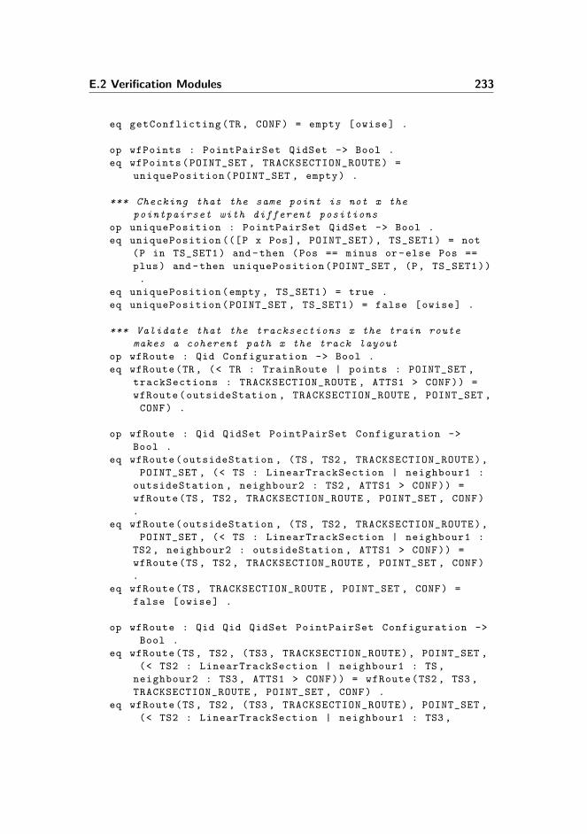
E.2 Verification Modules 233
eq getConflicting(TR, CONF) = empty [owise] .
op wfPoints : PointPairSet QidSet -> Bool .
eq wfPoints(POINT_SET , TRACKSECTION_ROUTE) =
uniquePosition(POINT_SET , empty) .
*** Checking that the same point is not x the
pointpairset with different positions
op uniquePosition : PointPairSet QidSet -> Bool .
eq uniquePosition (([P x Pos], POINT_SET), TS_SET1) = not
(P in TS_SET1) and -then (Pos == minus or-else Pos ==
plus) and -then uniquePosition(POINT_SET , (P, TS_SET1))
.
eq uniquePosition(empty , TS_SET1) = true .
eq uniquePosition(POINT_SET , TS_SET1) = false [owise] .
*** Validate that the tracksections x the train route
makes a coherent path x the track layout
op wfRoute : Qid Configuration -> Bool .
eq wfRoute(TR, (< TR : TrainRoute | points : POINT_SET ,
trackSections : TRACKSECTION_ROUTE , ATTS1 > CONF)) =
wfRoute(outsideStation , TRACKSECTION_ROUTE , POINT_SET ,
CONF) .
op wfRoute : Qid QidSet PointPairSet Configuration ->
Bool .
eq wfRoute(outsideStation , (TS, TS2 , TRACKSECTION_ROUTE),
POINT_SET , (< TS : LinearTrackSection | neighbour1 :
outsideStation , neighbour2 : TS2 , ATTS1 > CONF)) =
wfRoute(TS , TS2 , TRACKSECTION_ROUTE , POINT_SET , CONF)
.
eq wfRoute(outsideStation , (TS, TS2 , TRACKSECTION_ROUTE),
POINT_SET , (< TS : LinearTrackSection | neighbour1 :
TS2 , neighbour2 : outsideStation , ATTS1 > CONF)) =
wfRoute(TS , TS2 , TRACKSECTION_ROUTE , POINT_SET , CONF)
.
eq wfRoute(TS, TRACKSECTION_ROUTE , POINT_SET , CONF) =
false [owise] .
op wfRoute : Qid Qid QidSet PointPairSet Configuration ->
Bool .
eq wfRoute(TS, TS2 , (TS3 , TRACKSECTION_ROUTE), POINT_SET ,
(< TS2 : LinearTrackSection | neighbour1 : TS,
neighbour2 : TS3 , ATTS1 > CONF)) = wfRoute(TS2 , TS3 ,
TRACKSECTION_ROUTE , POINT_SET , CONF) .
eq wfRoute(TS, TS2 , (TS3 , TRACKSECTION_ROUTE), POINT_SET ,
(< TS2 : LinearTrackSection | neighbour1 : TS3 ,

234 Model and Verification Maude Modules
neighbour2 : TS, ATTS1 > CONF)) = wfRoute(TS2 , TS3 ,
TRACKSECTION_ROUTE , POINT_SET , CONF) .
eq wfRoute(TS, TS2 , (TS3 , TRACKSECTION_ROUTE), ([TS2 x
minus], POINT_SET), (< TS2 : Point | neighbour1 : TS3 ,
neighbour3 : TS, ATTS1 > CONF)) = wfRoute(TS2 , TS3 ,
TRACKSECTION_ROUTE , POINT_SET , CONF) .
eq wfRoute(TS, TS2 , (TS3 , TRACKSECTION_ROUTE), ([TS2 x
plus], POINT_SET), (< TS2 : Point | neighbour1 : TS3 ,
neighbour2 : TS, ATTS1 > CONF)) = wfRoute(TS2 , TS3 ,
TRACKSECTION_ROUTE , POINT_SET , CONF) .
eq wfRoute(TS, TS2 , (TS3 , TRACKSECTION_ROUTE), ([TS2 x
minus], POINT_SET), (< TS2 : Point | neighbour1 : TS,
neighbour3 : TS3 , ATTS1 > CONF)) = wfRoute(TS2 , TS3 ,
TRACKSECTION_ROUTE , POINT_SET , CONF) .
eq wfRoute(TS, TS2 , (TS3 , TRACKSECTION_ROUTE), ([TS2 x
plus], POINT_SET), (< TS2 : Point | neighbour1 : TS,
neighbour2 : TS3 , ATTS1 > CONF)) = wfRoute(TS2 , TS3 ,
TRACKSECTION_ROUTE , POINT_SET , CONF) .
eq wfRoute(TS, TS2 , empty , POINT_SET , CONF) = true .
eq wfRoute(TS, TS2 , TRACKSECTION_ROUTE , POINT_SET , CONF)
= false [owise] .
op wfLocking : Qid Configuration -> Bool .
eq wfLocking(TR, (< TR : TrainRoute | points : POINT_SET ,
locking : [BEGIN x END], ATTS1 > CONF)) = wfLocking ([
BEGIN x END], POINT_SET , CONF) .
*** The locking pair is two track sections next to each
other
op wfLocking : LockingPair PointPairSet Configuration ->
Bool .
eq wfLocking ([BEGIN x END], POINT_SET , (< BEGIN :
LinearTrackSection | neighbour1 : TS, neighbour2 : TS2
, ATTS1 > CONF)) = TS == END or-else TS2 == END .
eq wfLocking ([BEGIN x END], ([ BEGIN x Pos], POINT_SET),
(< BEGIN : Point | neighbour1 : TS , neighbour2 : TS2 ,
neighbour3 : TS3 , ATTS1 > CONF)) = (TS == END) or-else
(TS2 == END and -then Pos == plus) or-else (TS3 == END
and -then Pos == minus) .
eq wfLocking ([BEGIN x END], POINT_SET , CONF) = false [
owise] .
*** ******************************************
**** AUXILIARY OPERATORS ****
*** ******************************************
op allRelays : -> Configuration .

E.2 Verification Modules 235
eq allRelays = relays(confOf(initState)) .
op relays : Configuration -> Configuration .
eq relays(< R : V@Relay | ATTS1 > CONF) = < R : V@Relay |
ATTS1 > relays(CONF) .
eq relays(CONF) = none [owise] .
op allRegularRelays : -> Configuration .
eq allRegularRelays = regularRelays(confOf(initState)) .
op regularRelays : Configuration -> Configuration .
eq regularRelays(< R : RegularRelay | ATTS1 > CONF) = < R
: RegularRelay | ATTS1 > regularRelays(CONF) .
eq regularRelays(CONF) = none [owise] .
op allSteelCoreRelays : -> Configuration .
eq allSteelCoreRelays = steelCoreRelays(confOf(initState)
) .
op steelCoreRelays : Configuration -> Configuration .
eq steelCoreRelays(< S : SteelCoreRelay | ATTS1 > CONF) =
< S : SteelCoreRelay | ATTS1 > steelCoreRelays(CONF)
.
eq steelCoreRelays(CONF) = none [owise] .
op allContacts : -> Configuration .
eq allContacts = contacts(confOf(initState)) .
op contacts : Configuration -> Configuration .
eq contacts(< C : Contact | ATTS1 > CONF) = < C : Contact
| ATTS1 > contacts(CONF) .
eq contacts(CONF) = none [owise] .
op allLamps : -> Configuration .
eq allLamps = lamps(confOf(initState)) .
op lamps : Configuration -> Configuration .
eq lamps(< C : Lamp | ATTS1 > CONF) = < C : Lamp | ATTS1
> lamps(CONF) .
eq lamps(CONF) = none [owise] .
op allButtons : -> Configuration .
eq allButtons = buttons(confOf(initState)) .
op buttons : Configuration -> Configuration .
eq buttons(< B : Button | ATTS1 > CONF) = < B : Button |
ATTS1 > buttons(CONF) .
eq buttons(CONF) = none [owise] .
op allSignals : -> Configuration .
eq allSignals = signals(confOf(initState)) .
op signals : Configuration -> Configuration .

236 Model and Verification Maude Modules
eq signals(< S : Signal | ATTS1 > CONF) = < S : Signal |
ATTS1 > signals(CONF) .
eq signals(CONF) = none [owise] .
op allLinearTrackSections : -> Configuration .
eq allLinearTrackSections = linearTrackSections(confOf(
initState)) .
op linearTrackSections : Configuration -> Configuration .
eq linearTrackSections(< TS : LinearTrackSection | ATTS1
> CONF) = < TS : LinearTrackSection | ATTS1 >
linearTrackSections(CONF) .
eq linearTrackSections(CONF) = none [owise] .
op allTrackSections : -> Configuration .
eq allTrackSections = trackSections(confOf(initState)) .
op trackSections : Configuration -> Configuration .
eq trackSections(< TS : V@TrackSection | ATTS1 > CONF) =
< TS : V@TrackSection | ATTS1 > trackSections(CONF) .
eq trackSections(CONF) = none [owise] .
op allPoints : -> Configuration .
eq allPoints = points(confOf(initState)) .
op points : Configuration -> Configuration .
eq points(< P : Point | ATTS1 > CONF) = < P : Point |
ATTS1 > points(CONF) .
eq points(CONF) = none [owise] .
op allTrains : -> Configuration .
eq allTrains = trains(confOf(initState)) .
op trains : Configuration -> Configuration .
eq trains(< T : Train | ATTS1 > CONF) = < T : Train |
ATTS1 > trains(CONF) .
eq trains(CONF) = none [owise] .
op allTrainRoutes : -> Configuration .
eq allTrainRoutes = trainRoutes(confOf(initState)) .
op trainRoutes : Configuration -> Configuration .
eq trainRoutes(< TR : TrainRoute | ATTS1 > CONF) = < TR :
TrainRoute | ATTS1 > trainRoutes(CONF) .
eq trainRoutes(CONF) = none [owise] .
op componentsExist : QidSet Configuration -> Bool .
eq componentsExist ((C, Cs), (< C : V@ElectricalComponent
| ATTS1 > CONF)) = componentsExist(Cs, CONF) .
eq componentsExist(empty , CONF) = true .
eq componentsExist(Cs, CONF) = false [owise] .

E.2 Verification Modules 237
op signalsExist : QidSet Configuration -> Bool .
eq signalsExist ((S, Ss), (< S : Signal | lamps : Ls >
CONF)) = signalsExist(Ss, CONF) .
eq signalsExist ((noSignal , Ss), CONF) = signalsExist(Ss,
CONF) .
eq signalsExist(empty , CONF) = true .
eq signalsExist(Ss, CONF) = false [owise] .
endm
E.2.2 PREDICATES
mod PREDICATES is
pr WELL -FORMED .
inc SATISFACTION .
subsort Configuration < State .
vars TR TR1 TR2 S S1 S2 C R L R+ R- P T : Qid .
vars LS Cs TRs1 TRs2 : QidSet .
var A : Bool .
var COL : Color .
var POS : Position .
vars ATTS ATTS1 ATTS2 ATTS3 ATTS4 : AttributeSet .
var CONF : Configuration .
*** *****************************************************
*** ****** COMMON *********
*** *****************************************************
op idle : -> Prop .
eq { CONF } |= idle = idle(CONF) .
*** *****************************************************
*** ****** CIRCUIT *********
*** *****************************************************
--------------------------------------------------------
--- Specifies whether any steel core relay at any time
--- carries drawing as well as dropping current.
--- (illegal state)
--------------------------------------------------------
op drawAndDropSteelCoreRelay : -> Prop .
ceq {
< S : SteelCoreRelay | drawn : A, droppingComponent
: C, drawingComponents : Cs >
CONF
} |= drawAndDropSteelCoreRelay = true

238 Model and Verification Maude Modules
if conducting(S, (< S : SteelCoreRelay | drawn : A,
droppingComponent : C, drawingComponents : Cs > CONF))
and -then conducting(C, (< S : SteelCoreRelay | drawn : A,
droppingComponent : C, drawingComponents : Cs > CONF)
)
and -then anyConducting(Cs, (< S : SteelCoreRelay | drawn
: A, droppingComponent : C, drawingComponents : Cs >
CONF)) .
eq { CONF } |= drawAndDropSteelCoreRelay = false [owise]
.
--------------------------------------------------------
--- Specifies whether the relay associated with the
--- id is drawn.
--------------------------------------------------------
op isDrawn : Qid -> Prop .
eq { CONF } |= isDrawn(R) = isDrawn(R, CONF) .
--------------------------------------------------------
--- Specifies whether a relay can draw
--------------------------------------------------------
op canDraw : Qid -> Prop .
eq { CONF } |= canDraw(R) = canDraw(R, CONF) .
--------------------------------------------------------
--- Specifies whether a relay can drop
--------------------------------------------------------
op canDrop : Qid -> Prop .
eq { CONF } |= canDrop(R) = canDrop(R, CONF) .
*** *****************************************************
*** ****** TRACK LAYOUT *********
*** *****************************************************
--------------------------------------------------------
--- Specifies whether a given signal is displaying a
given color
--------------------------------------------------------
op aspect : Qid Color -> Prop .
ceq {
< S : Signal | lamps : (L, LS) >
< L : Lamp | color : COL >
CONF
} |= aspect(S, COL) = true
if
shines(L, (< S : Signal | lamps : (L, LS) > < L :
Lamp | color : COL > CONF))

E.2 Verification Modules 239
and -then
not shines(LS, (< S : Signal | lamps : (L, LS) > <
L : Lamp | color : COL > CONF)) .
eq { CONF } |= aspect(S, COL) = false [owise] .
--------------------------------------------------------
--- Specifies whether a given point is in the given
--- position
--------------------------------------------------------
op inPosition : Qid Position -> Prop .
eq { < P : Point | relay+ : R+, ATTS > < R+ :
RegularRelay | drawn : true > CONF } |= inPosition(P,
plus) = true .
eq { < P : Point | relay - : R-, ATTS > < R- :
RegularRelay | drawn : true > CONF } |= inPosition(P,
minus) = true .
eq { < P : Point | relay+ : R+, relay - : R-, ATTS > < R+
: RegularRelay | drawn : false > < R- : RegularRelay |
drawn : false > CONF } |= inPosition(P, intermediate)
= true .
eq { CONF } |= inPosition(P, POS) = false [owise] .
*** *****************************************************
*** ****** TRAIN *********
*** *****************************************************
--------------------------------------------------------
--- Specifies whether an external event can occur
--------------------------------------------------------
op idle : -> Prop .
eq { CONF } |= idle = idle(CONF) .
--------------------------------------------------------
--- Specifies whether a collision takes place , i.e.
--- whether two trains occupy the same track section
--- at the same time
--------------------------------------------------------
op hasCollision : -> Prop .
eq { CONF } |= hasCollision = hasCollision(CONF) .
--------------------------------------------------------
--- Specifies whether a derailing takes place , i.e.
--- a train occupies a point and the point is in the
--- intermediate position
--------------------------------------------------------
op hasDerailing : -> Prop .
eq { CONF } |= hasDerailing = hasDerailing(CONF) .

240 Model and Verification Maude Modules
--------------------------------------------------------
--- Specifies whether a track section is occupied
--------------------------------------------------------
op isOccupied : Qid -> Prop .
eq { CONF } |= isOccupied(T) = isOccupied(T, CONF) .
*** *****************************************************
*** ****** TRAIN ROUTE TABLE *********
*** *****************************************************
--------------------------------------------------------
--- Determines if a train route is locked
--------------------------------------------------------
op isLocked : Qid -> Prop .
eq { < TR : TrainRoute | lockRelay : S, ATTS1 > < S :
SteelCoreRelay | drawn : A, ATTS2 > CONF } |= isLocked
(TR) = not A .
eq { CONF } |= isLocked(TR) = false [owise] .
--------------------------------------------------------
--- Determines if two conflicting train routes
--- are locked
--------------------------------------------------------
op conflictingLocked : -> Prop .
eq {
< TR1 : TrainRoute | lockRelay : S1, conflicting : (
TR2 TRs1), ATTS1 >
< S1 : SteelCoreRelay | drawn : false , ATTS2 >
< TR2 : TrainRoute | lockRelay : S2, conflicting : (
TR1 TRs2), ATTS3 >
< S2 : SteelCoreRelay | drawn : false , ATTS4 >
CONF } |= conflictingLocked = true .
eq { CONF } |= conflictingLocked = false [owise] .
endm
E.2.3 CONFIDENCE-CONDITIONS
mod CONFIDENCE -CONDITIONS is
pr PREDICATES .
pr MODEL -CHECKER .
pr LTL -SIMPLIFIER .
var A : Bool .
var R : Qid .
var V@Relay : Relay .
var ATTS : AttributeSet .

E.2 Verification Modules 241
var CONF : Configuration .
op drawConfidenceCondition : -> Prop .
eq drawConfidenceCondition = [] drawCondition(confOf(
initState)) .
op drawCondition : Configuration -> Prop .
eq drawCondition ((< R : V@Relay | drawn : A, ATTS > CONF)
) = (canDraw(R) -> O (~ canDraw(R) -> isDrawn(R))) /\
drawCondition(CONF) .
eq drawCondition(CONF) = True [owise] .
op dropConfidenceCondition : -> Prop .
eq dropConfidenceCondition = [] (dropCondition(confOf(
initState))) .
op dropCondition : Configuration -> Prop .
eq dropCondition ((< R : V@Relay | drawn : A, ATTS > CONF)
) = (canDrop(R) -> O (~ canDrop(R) -> ~ isDrawn(R)))
/\ dropCondition(CONF) .
eq dropCondition(CONF) = True [owise] .
endm
E.2.4 VERIFICATION
mod VERIFICATION is
pr SAFETY -PROPERTIES .
vars T1 T2 : TransitionList .
var modelCheckResult : ModelCheckResult .
op hasCounterExample : ModelCheckResult -> Bool .
eq hasCounterExample(counterexample(T1, T2)) = true .
eq hasCounterExample(modelCheckResult) = false [owise] .
endm
E.2.5 SAFETY-PROPERTIES
mod SAFETY -PROPERTIES is
pr CONFIDENCE -CONDITIONS .
var C : Color .
vars R P S T TR TS FIRST SECOND : Qid .
vars TRS TSS : QidSet .
vars TSs1 TSs2 : QidList .
var POS : Position .
var SPS : SignalPairSet .

242 Model and Verification Maude Modules
var PPS : PointPairSet .
vars ATTS ATTS1 ATTS2 ATTS3 : AttributeSet .
var CONF : Configuration .
vars F1 F2 : Formula .
*** *****************************************************
*** All safety properties
*** *****************************************************
op allSafetyProp : Configuration -> Formula .
eq allSafetyProp(CONF) = [] (
safetyPropSignals1(CONF) /\ safetyPropSignals2(CONF)
/\ safetyPropPoints(CONF) /\
safetyPropStop(CONF) /\ safetyPropReleaseInit(CONF) /\
safetyPropInitToFina(CONF) /\
safetyPropReleaseFina(CONF) /\ safetyPropNoMutLock(
CONF)) .
*** *****************************************************
*** Safety properties for signals
*** *****************************************************
op safetyPropSignals1 : -> Formula .
eq safetyPropSignals1 = [] (safetyPropSignals1(confOf(
initState))) .
op safetyPropSignals1 : Configuration -> Formula .
eq safetyPropSignals1(< TR : TrainRoute | signals : SPS ,
ATTS > CONF ) =
(isLocked(TR) -> (allSignalsNotGreen(SPS))) /\
safetyPropSignals1(CONF) .
eq safetyPropSignals1(CONF) = True [owise] .
op allSignalsNotGreen : SignalPairSet -> Formula .
eq allSignalsNotGreen (([S x green], SPS)) =
allSignalsNotGreen(SPS) .
eq allSignalsNotGreen (([S x C], SPS)) =
aspect(S, C) /\ allSignalsNotGreen(SPS) [owise] .
eq allSignalsNotGreen(empty) = True .
op safetyPropSignals2 : -> Formula .
eq safetyPropSignals2 = [] (safetyPropSignals2(confOf(
initState))) .
op safetyPropSignals2 : Configuration -> Formula .
eq safetyPropSignals2 ((< TR : TrainRoute | trackSections
: TSS , ATTS > CONF)) =
(( isLocked(TR) /\ (allTrackSectionsFree(TSS)) /\ idle)
-> aspect(getStopSignal(TR, (< TR : TrainRoute |

E.2 Verification Modules 243
trackSections : TSS , ATTS > CONF )), green)) /\
safetyPropSignals2(CONF) .
eq safetyPropSignals2(CONF) = True [owise] .
op allTrackSectionsFree : QidSet -> Formula [memo] .
eq allTrackSectionsFree ((TS, TSS)) = isOccupied(TS) /\
allTrackSectionsFree(TSS) .
eq allTrackSectionsFree(empty) = True .
*** *****************************************************
*** Safety properties for points
*** *****************************************************
op safetyPropPoints : -> Formula .
eq safetyPropPoints = [] (safetyPropPoints(confOf(
initState))) .
op safetyPropPoints : Configuration -> Formula .
eq safetyPropPoints(< TR : TrainRoute | points : PPS ,
ATTS > CONF ) =
(isLocked(TR) -> (points(PPS))) /\ safetyPropPoints(
CONF) .
eq safetyPropPoints(CONF) = True [owise] .
op points : PointPairSet -> Formula .
eq points (([P x POS], PPS)) =
inPosition(P, POS) /\ points(PPS) .
eq points(empty) = True .
*** *****************************************************
*** Safety properties for display stop signal
*** *****************************************************
op safetyPropStop : -> Formula .
eq safetyPropStop = [] (safetyPropStop(confOf(initState))
) .
op safetyPropStop : Configuration -> Formula .
eq safetyPropStop(< TR : TrainRoute | displayStop : TS,
ATTS > CONF ) =
(( isLocked(TR) /\ isOccupied(TS) /\ idle) -> aspect(
getStopSignal(TR, (< TR : TrainRoute | displayStop
: TS, ATTS > CONF )), red)) /\ safetyPropStop(CONF)
.
eq safetyPropStop(CONF) = True [owise] .
*** *****************************************************
*** Safety properties for initiating the train
*** route release

244 Model and Verification Maude Modules
*** *****************************************************
op safetyPropReleaseInit : -> Formula .
eq safetyPropReleaseInit = [] (safetyPropReleaseInit(
confOf(initState))) .
op safetyPropReleaseInit : Configuration -> Formula .
eq safetyPropReleaseInit(< TR : TrainRoute | locking : [
FIRST x SECOND], ATTS > CONF ) =
((~ isLocked(TR) /\ O isLocked(TR)) -> O (isOccupied(
FIRST) /\ ~ isOccupied(SECOND) R isLocked(TR))) /\
safetyPropReleaseInit(CONF) .
eq safetyPropReleaseInit(CONF) = True [owise] .
*** *****************************************************
*** Safety properties for lock of train route from
*** initiate to finalisatation of release
*** *****************************************************
op safetyPropInitToFina : -> Formula .
eq safetyPropInitToFina = [] (safetyPropInitToFina(confOf
(initState))) .
op safetyPropInitToFina : Configuration -> Formula .
eq safetyPropInitToFina(< TR : TrainRoute | locking : [
FIRST x SECOND], ATTS > CONF ) =
(( isLocked(TR) /\ isOccupied(FIRST) /\ ~ isOccupied(
SECOND)) -> (~ isOccupied(FIRST) /\ isOccupied(
SECOND) R isLocked(TR))) /\ safetyPropInitToFina(
CONF) .
eq safetyPropInitToFina(CONF) = True [owise] .
*** *****************************************************
*** Safety properties for finalising the train
*** route release
*** *****************************************************
op safetyPropReleaseFina : -> Formula .
eq safetyPropReleaseFina = [] (safetyPropReleaseFina(
confOf(initState))) .
op safetyPropReleaseFina : Configuration -> Formula .
eq safetyPropReleaseFina(< TR : TrainRoute | locking : [
FIRST x SECOND], ATTS > CONF ) =
(( isLocked(TR) /\ O ~ isLocked(TR)) -> (~ isOccupied(
FIRST) /\ isOccupied(SECOND))) /\
safetyPropReleaseFina(CONF) .
eq safetyPropReleaseFina(CONF) = True [owise] .
*** *****************************************************

E.2 Verification Modules 245
*** Safety properties for mutually conflicting
*** train routes
*** *****************************************************
op safetyPropNoMutLock : -> Formula .
eq safetyPropNoMutLock = [] (safetyPropNoMutLock(confOf(
initState))) .
op safetyPropNoMutLock : Configuration -> Formula .
eq safetyPropNoMutLock(< TR : TrainRoute | conflicting :
TRS , ATTS > CONF ) =
(~ isLocked(TR) \/ (locked(TRS))) /\
safetyPropNoMutLock(CONF) .
eq safetyPropNoMutLock(CONF) = True [owise] .
op locked : QidSet -> Formula [memo] .
eq locked ((TR, TRS)) =
~ isLocked(TR) /\ locked(TRS) .
eq locked(empty) = True .
*** *****************************************************
*** A train occupies a track section outside a
*** locked TR
*** *****************************************************
op safetyPropUnauthTrain : -> Prop .
eq {CONF} |= safetyPropUnauthTrain =
safetyPropUnauthTrain(CONF) .
op safetyPropUnauthTrain : Configuration -> Bool .
ceq safetyPropUnauthTrain(
< T : Train | occupiedSections : (TSs1 TS TSs2), ATTS
>
< TS : LinearTrackSection | platform : false , ATTS1 >
CONF) = true
if inNoLockedTrainRoute(TS, CONF) .
eq safetyPropUnauthTrain(CONF) = false [owise] .
op inNoLockedTrainRoute : Qid Configuration -> Bool .
eq inNoLockedTrainRoute(TS,
(< TR : TrainRoute | lockRelay : S, trackSections : (
TS, TSS), ATTS2 >
< S : SteelCoreRelay | drawn : false , ATTS3 >
CONF)) = false .
eq inNoLockedTrainRoute(TS, CONF) = true [owise] .
endm

246 Model and Verification Maude Modules

Appendix F
Maude Example Modules
In this section the modules used to explain how Maude works in chapter 3 arelisted.
F.1 PERSON3
This module is used in section 3.3.8
mod PERSON3 is
pr CONFIGURATION .
pr INT .
sort Location .
ops atHome atShop atWork : -> Location .
op Person : -> Cid .
ops p1 p2 : -> Oid .
op location :_ : Location -> Attribute .
op coins :_ : Int -> Attribute .
op items :_ : Int -> Attribute .
var P : Oid .
vars C I : Int .

248 Maude Example Modules
var ATTS : AttributeSet .
rl [gotoWork] :
< P : Person | location : atHome , coins : C, items : I
>
=>
< P : Person | location : atWork , coins : C, items : I
> .
rl [doWork] :
< P : Person | location : atWork , coins : C, items : I
>
=>
< P : Person | location : atWork , coins : (C + 1),
items : I > .
rl [leaveWork] :
< P : Person | location : atWork , coins : C, items : I
>
=>
< P : Person | location : atHome , coins : C, items : I
> .
rl [gotoShop] :
< P : Person | location : atHome , coins : C, items : I
>
=>
< P : Person | location : atShop , coins : C, items : I
> .
crl [doShop] :
< P : Person | location : atShop , coins : C, items : I
>
=>
< P : Person | location : atShop , coins : (C - 1),
items : (I + 1) >
if C > 0 .
rl [leaveShop] :
< P : Person | location : atShop , coins : C, items : I
>
=>
< P : Person | location : atHome , coins : C, items : I
> .
op s : -> Configuration .
eq s =

F.2 PERSON3-QID 249
< p1 : Person | location : atHome , coins : 0, items :
0 >
< p2 : Person | location : atHome , coins : 1, items :
3 > .
endm
search [,20] s =>* < p1 : Person | location : atHome , coins
: C:Int , items : I:Int > C:Configuration such that I > 2
.
search [,20] s =>* < p1 : Person | location : atHome , coins
: C:Int , items : I:Int > C:Configuration such that I > 1
.
F.2 PERSON3-QID
This module is used in section 3.3.8
mod PERSON3 -QID is
pr CONFIGURATION .
pr INT .
pr QID .
sort Location .
subsort Qid < Oid .
ops atHome atShop atWork : -> Location .
op Person : -> Cid .
op location :_ : Location -> Attribute .
op coins :_ : Int -> Attribute .
op items :_ : Int -> Attribute .
var P : Qid .
vars C I : Int .
var ATTS : AttributeSet .
rl [gotoWork] :
< P : Person | location : atHome , coins : C, items : I
>
=>
< P : Person | location : atWork , coins : C, items : I
> .
rl [doWork] :
< P : Person | location : atWork , coins : C, items : I
>
250 Maude Example Modules
=>
< P : Person | location : atWork , coins : (C + 1),
items : I > .
rl [leaveWork] :
< P : Person | location : atWork , coins : C, items : I
>
=>
< P : Person | location : atHome , coins : C, items : I
> .
rl [gotoShop] :
< P : Person | location : atHome , coins : C, items : I
>
=>
< P : Person | location : atShop , coins : C, items : I
> .
crl [doShop] :
< P : Person | location : atShop , coins : C, items : I
>
=>
< P : Person | location : atShop , coins : (C - 1),
items : (I + 1) >
if C > 0 .
rl [leaveShop] :
< P : Person | location : atShop , coins : C, items : I
>
=>
< P : Person | location : atHome , coins : C, items : I
> .
endm
F.3 PERSON3-SAT
This module is used in section 3.3.10.1
mod PERSON3 -SAT is
pr PERSON3 .
pr SATISFACTION .
subsort Configuration < State .
var Conf : Configuration .
F.3 PERSON3-SAT 251
var P : Oid .
var I : Int .
var ATTS : AttributeSet .
op hasItems : Oid -> Prop .
eq < P : Person | items : I, ATTS > Conf |= hasItems(P) =
I > 0 .
op s : -> Configuration .
eq s =
< p1 : Person | location : atHome , coins : 0, items :
0 >
< p2 : Person | location : atHome , coins : 2, items :
3 > .
endm

252 Maude Example Modules

Appendix G
Point Solution
This appendix briefly summarises our solution for modelling the fragment of thecircuit which controls points. In the domain the switching of a point is controlledby the circuit. In this project we have focused on obtaining an accurate modelof the point behaviour, and for this reason we have chosen to model the pointbehaviour with circuit functionality in accordance with the domain. The circuitfrom BaneDanmark describing the point behaviour is very complex though andfor this reason we have simplified it. The modelling of a point is still much moreaccurate than e.g. the solution made in [5], see section 9.3.1.
Three figures are used in the description of this solution. Each figure correspondsto the state when the associated point is in the plus position.
For each point on a station three subcircuits consisting of two buttons, fourregular relays, two steel core relays and eight contacts are created. Figure G.1shows the first subcircuit. The subcircuit has two buttons which are used toswitch the position of the point. Button b1-Minus is used to switch the pointinto the minus position and button b1-Plus is used to switch the point intothe plus position. The two contacts in figure G.1 are contacts of steel corerelay representing the states of two train routes. For each train route, thatrequires this point to be in a specific position when being locked, an uppercontact is added to the sequence of contacts before the buttons. This ensuresthat whenever one of the train routes is locked (and the associated steel core

254 Point Solution
Figure G.1: For each point, a subcircuit consisting two buttons and two relays moni-toring the buttons is created. The buttons are used to control the position of the point.The two contacts belong to two steel core relays stating whether train routes 1 and 3 arelocked. If either of the train routes are locked, and thus the steel core relay is dropped,the corresponding contact is open and current cannot pass form the positive pole to thebuttons. For each train route this point is part of, a related contact is added to thesequence of contacts. This ensures that points can only be switched if no train route,that has requirements to this point, is locked.
relay is dropped) current cannot propagate to the buttons and thus the pointcannot change. Each button is connected to a regular relay that is used tomonitor whether the buttons are pushed or not. The reason for this is that forthe solution to work, current must be cut from some components if a buttonis pushed, while it must allow current to propagate through other components.This is illustrated in the subcircuit in figure G.2.
The four contacts in the top part of figure G.2 reads the state of the two buttons.The combination of the contacts makes sure that only one of the paths leadingfrom the positive poles can be conducting at a time and only if exactly one ofthe buttons is pushed. In the bottom part of the subcircuit we see the two steelcore relays depicting the position of the point. If scr-1-Minus is drawn, thepoint is in the minus position, if scr-1-Plus is drawn, the point is in the plusposition, and finally, if neither relay is drawn, the point is in the intermediateposition. The drawing part of each of the steel core relays is guarded by a lowercontact of a regular relay mirroring the state of the other steel core relay. Thisensures that if one of the steel core relays are drawn, current cannot propagateto the drawing path of the other steel core relay. Even in the states where bothrelays are dropped, current cannot propagate through the drawing parts of bothrelays. This is restricted by the combination of the contacts in the top of the

255
Figure G.2: The subcircuit of a point consisting of contacts of the relays monitoringthe buttons and the steel core relays defining the position of the point. As the relay“scr-1-Plus” is drawn, the associated point is in the plus position.
figure.
When the button for the minus position is pushed, and the associated relay(button-) is drawn, current can only propagate through the dropping part of therelay for the plus position (scr-1-Plus) to have it (and the mirroring relay, plus)drop, and subsequently cut the current from the dropping part of the relay, asrequested by the domain1. When both the steel core relay and regular relay forthe plus position are dropped, current can only propagate through the drawingpart of the steel core relay for the minus position (scr-1-Minus) to have it (andthe mirroring relay, minus) draw. In this state, nothing else can happen, untilthe button for the minus position is released and the button for the plus position(button+) is pushed.
Figure G.3 shows the third and final subcircuit of the point solution. Thisfigure simply shows the regular relays mirroring the states of the steel corerelays in figure G.2. They provide no additional functionality to the point,except monitoring the position of the relay.
Figure 5.9 shows an example of a track layout containing a point and three
1Current must be cut from the dropping part of a steel core relay, when this is dropped.This is a requirement as the steel core relay can be damaged if it is continuously demagnetised.

256 Point Solution
Figure G.3: The subcircuit of a point consisting of two relays and two contacts. Theserelays are used to monitor the state of the steel core relays, representing the positionof the point. As the point is in the plus position, the associated regular relay “plus” isdrawn to mirror the state of the steel core relay “scr-1-Plus”.
connected track sections. The objects created to model this simple track layoutcan be seen below:
*** Track sections
< ’ts1 : LinearTrackSection | relay : ’ts1 -111, length : 30,
neighbour1 : outsideStation , neighbour2 : ’p1, signal1 :
noSignal , signal2 : noSignal >
< ’ts2 : LinearTrackSection | relay : ’ts2 -311, length : 30,
neighbour1 : ’p1, neighbour2 : outsideStation , signal1 :
noSignal , signal2 : noSignal >
< ’ts3 : LinearTrackSection | relay : ’ts3 -310, length : 30,
neighbour1 : ’p1, neighbour2 : outsideStation , signal1 :
noSignal , signal2 : noSignal >
< ’p1 : Point | relay : ’p1 -110, relay+ : ’p1 -211, relay - :
’p1 -210, length : 30, neighbour1 : ’ts1 , neighbour2 : ’
ts3 , signal1 : noSignal , signal2 : noSignal , neighbour3 :
’ts2 , signal3 : noSignal >
*** Relays for monitoring whether track sections are
occupied
< ’ts1 -111 : RegularRelay | drawn : false >
< ’ts2 -311 : RegularRelay | drawn : false >
< ’ts3 -310 : RegularRelay | drawn : false >
< ’p1 -110 : RegularRelay | drawn : false >
*** Contacts for monitoring the state of the train routes
< ’tr1 -410-c2 : Contact | relay : ’tr1 -410 upper : true >
< ’tr3 -411-c2 : Contact | relay : ’tr3 -411 upper : true >
*** Relays for monitoring the position of the point
< ’p1 -211 : RegularRelay | drawn : false >

257
< ’p1 -210 : RegularRelay | drawn : false >
*** Objects for the point solution
< ’scr -1-Plus : SteelCoreRelay | drawn : true ,
droppingComponent : ’scr -1-Plus -c1, drawingComponents :
(’p1 -210-c6) >
< ’scr -1-Minus : SteelCoreRelay | drawn : false ,
droppingComponent : ’scr -1-Minus -c1, drawingComponents :
(’p1 -211-c6) >
< ’button -1-Plus : RegularRelay | drawn : false >
< ’button -1-Minus : RegularRelay | drawn : false >
< ’button -1-Minus -c1 : Contact | relay : ’button -1-Minus ,
upper : true >
< ’button -1-Plus -c6 : Contact | relay : ’button -1-Plus ,
upper : false >
< ’button -1-Minus -c6 : Contact | relay : ’button -1-Minus ,
upper : false >
< ’button -1-Plus -c1 : Contact | relay : ’button -1-Plus ,
upper : true >
< ’p1 -211-c6 : Contact | relay : ’p1 -211, upper : false >
< ’p1 -210-c6 : Contact | relay : ’p1 -210, upper : false >
< ’scr -1-Plus -c1 : Contact | relay : ’scr -1-Plus , upper :
true >
< ’scr -1-Plus -c2 : Contact | relay : ’scr -1-Plus , upper :
true >
< ’scr -1-Minus -c1 : Contact | relay : ’scr -1-Minus , upper :
true >
< ’scr -1-Minus -c2 : Contact | relay : ’scr -1-Minus , upper :
true >
< ’b-1-Plus : Button | pushed : false >
< ’b-1-Minus : Button | pushed : false >

258 Point Solution

Appendix H
Test
This section will describe how tests of the model has been executed in thisproject. Originally a test tool was developed for this purpose, see section 8.2but as the various versions of the model have been created when it was discoveredthat the Kripke structure of the model was too big, the tool has unfortunatelynot been updated.
Tests have been executed for different subsets of interlocking systems. Thetests are executed by specifying the subset of an interlocking system in theMaude module INIT-STATE and then executing reduce commands in Maude.The following sections will describe how this is done when a test is made fromscratch and when an existing test is to be executed.
H.1 Creating and Running New Tests
The following steps describe how an interlocking system is designed and howit can be tested afterwards. The test mentioned in section 7.2 is used as anexample below.
1. Copy the content of the /maudeModules folder on the CD to a folder on

260 Test
your computer.
2. Run Maude as described in appendix B, navigate to the folder from item1.
3. Design a test scenario in the extended Simulator as described in appendixK.1.
4. Export the interlocking system project to Maude as explained in ap-pendix K.1, this creates a file containing the specification of the inter-locking system in Maude. The exported file should overwrite the fileinitState.maude in the folder from item 1. The configuration for thesmall interlocking system defined in section 7.2 can be seen on page 260.
5. Load the file noChecks.maude in Maude:load noChecks.maude
6. Enter the test command in Maude and execute it. For the test examplementioned in section 7.2 the test would be:
reduce in VERIFICATION : hasCounterExample(modelCheck(
initState , []~ hasCollision)) .
The result of the test is:
reduce in VERIFICATION : hasCounterExample(modelCheck(
initState , []~ hasCollision)) .
rewrites: 228 in 0ms cpu (0ms real) (~ rewrites/second)
result Bool: true
The Maude configuration of the small interlocking system defined in section 7.2is:
mod INIT -STATE is
pr TRAIN -ROUTE -TABLE .
op initState : -> Configuration .
op path1 : Configuration -> Bool .
op path2 : Configuration -> Bool .
op path3 : Configuration -> Bool .
op path4 : Configuration -> Bool .
op path5 : Configuration -> Bool .
var Conf : Configuration .

H.1 Creating and Running New Tests 261
var V@TrackSection : TrackSection .
vars R1 : Qid .
vars D1 : Bool .
vars ATTS : AttributeSet .
vars V1@Relay : Relay .
ceq path1(< ’ts3 : V@TrackSection | ATTS > Conf) = true
if not isOccupied(’ts3 , < ’ts3 : V@TrackSection | ATTS
> Conf) .
eq path1(Conf) = false [owise] .
ceq conducting(’ts3 -211, Conf) = true if path1(Conf) .
ceq path2(< ’ts2 : V@TrackSection | ATTS > Conf) = true
if not isOccupied(’ts2 , < ’ts2 : V@TrackSection | ATTS
> Conf) .
eq path2(Conf) = false [owise] .
ceq conducting(’ts2 -110, Conf) = true if path2(Conf) .
ceq path3(< ’ts1 : V@TrackSection | ATTS > Conf) = true
if not isOccupied(’ts1 , < ’ts1 : V@TrackSection | ATTS
> Conf) .
eq path3(Conf) = false [owise] .
ceq conducting(’ts1 -111, Conf) = true if path3(Conf) .
*** Path 4
eq path4(Conf) = true .
eq path4(Conf) = false [owise] .
ceq conducting(’gr, Conf) = true if path4(Conf) .
*** Path 5
eq path5(Conf) = true .
eq path5(Conf) = false [owise] .
ceq conducting(’roe , Conf) = true if path5(Conf) .
eq initState =
{
< ’ts3 -211 : RegularRelay | drawn : true >
< ’ts2 -110 : RegularRelay | drawn : true >
< ’ts1 -111 : RegularRelay | drawn : true >
< ’s2 : Signal | lamps : (’roe) >
< ’s1 : Signal | lamps : (’gr) >
< ’ts3 : LinearTrackSection | relay : ’ts3 -211, length
: 30, platform : false , neighbour1 : ’ts2 ,
neighbour2 : outsideStation , signal1 : noSignal ,
signal2 : ’s2 >

262 Test
< ’ts2 : LinearTrackSection | relay : ’ts2 -110, length
: 30, platform : true , neighbour1 : ’ts1 ,
neighbour2 : ’ts3 , signal1 : noSignal , signal2 :
noSignal >
< ’ts1 : LinearTrackSection | relay : ’ts1 -111, length
: 30, platform : false , neighbour1 :
outsideStation , neighbour2 : ’ts2 , signal1 : ’s1 ,
signal2 : noSignal >
< ’gr : Lamp | color : green >
< ’roe : Lamp | color : red >
< ’garage : Garage | trainLengths : ((5 ,10)) >
} .
endm
H.2 Running Existing Tests
In order to run tests for interlocking systems for which the .ris and .maude
files have already been created, (see section I.5 for an overview of the tests), thefollowing steps should be taken:
1. Copy the .maude test file from the relevant folder and override the fileinitState.maude mentioned in item 4 in section H.1.
2. Follow steps 5 and 6 in the list in section H.1 to run a test on the modelof the interlocking system.
H.3 Functional Tests
This section lists the tests used to verify the functionality of the model. Notethat the tests have not been updated for use with the latest version of the model.
H.3.1 Circuit
mod CIRCUIT -TESTS is
pr TEST -TEMPLATE .

H.3 Functional Tests 263
ops circuitTests test1001 test1002 test1003 test1004
test1005 test1006 test1007 test1008 test1009 test1010
test1011 test1012 test1013 test1014 test1015 test1016
test1017 test1018 test1019 test1020 test1021 test1022
test1023 test1024 test1025 test1026 test1027 test1028
test1029 test1030 test1031 test1032 test1033 test1034
test1035 test1036 test1037 test1038 test1039 test1040
test1041 test1042 test1043 test1044 test1045 test1046
test1047 test1048 test1049 test1050 test1051 test1052
test1053 test1054 test1055 test1056 test1057 test1058
test1059 test1060 test1101 test1102 test1103 test1104
test1105 test1106 test1107 test1108 test1109 test1110
test1111 test1112 test1113 test1114 test1115 test1116
test1117 test1118 test1119 test1120 test1121 test1122
test1123 test1124 test1125 test1126 test1127 test1128
test1129 test1130 test1131 test1132 test1133 test1134
test1135 test1136 test1137 test1138 test1139 test1140
test1141 test1142 test1143 test1144 test1145 test1146
test1147 test1148 test1149 test1150 test1151 test1152
test1153 : -> ModelCheckResult .
eq test1001 = modelCheck(init1001 , <> ([] (isDrawn(’r
-111)))) .
eq test1002 = modelCheck(init1005 , <> ([] (~ isDrawn(’r1
-111)))) .
eq test1003 = | pathsContainingAll(’r2 -110, (’path1 , ’
path2 , ’path3), confOf(init1007)) | == 2 .
eq test1004 = not anyConductingPath ((’path4), confOf(
init1007)) .
eq test1005 = not conducting ((’r1 -111 , ’r2 -110-c1),
confOf(init1007)) .
eq test1006 = modelCheck(init1002 , <> ([] (isDrawn(’r1
-111) /\ isDrawn(’r2 -110)))) .
eq test1007 = modelCheck(init1003 , <> ([] (isDrawn(’r1
-111) /\ isDrawn(’r2 -110)))) .
eq test1008 = modelCheck(init1004 , <> ([] (isDrawn(’r1
-111) /\ (~ isDrawn(’r2 -110)))) ) .
eq test1009 = modelCheck(init1006 , [] (isDrawn(’r1 -111)
-> (<> (~ isDrawn(’r1 -111)))) /\ [] ((~ isDrawn(’r1
-111)) -> (<> isDrawn(’r1 -111))) ) .
eq test1010 = true modelCheck(init1006 , [] (~
invalidConducting)) .
eq test1011 = modelCheck(init1008 , [] ((( isDrawn(’s1 -111)
/\ isPushed(’b)) -> (drawAndDropSteelCoreRelay)))) .
eq test1012 = modelCheck(init1009 , [] ((<> isPushed(’b))
/\ (<> (~ isPushed(’b)))) ).

264 Test
eq test1013 = modelCheck(init1010 , conducting ((’R1 -110-c6
, ’S1 -111-c1, ’S1 -111, ’R1 -110)) /\ ~ conducting ((’R1
-110-c1, ’S1 -111, ’R1 -110))) .
eq test1014 = modelCheck(init1010 , isDrawn(’S1 -111) /\ ~
isDrawn(’R1 -110)).
eq test1015 = modelCheck(init1012 , O (( isDrawn(’S1) /\
isDrawn(’R1 -111)) \/ (~ isDrawn(’S1) /\ ~ isDrawn(’R1
-111)))) .
eq test1016 = modelCheck(init1012 , O (O ( (isDrawn(’S1
-111) /\ isDrawn(’R1 -110)) \/ (~ isDrawn(’S1 -111) /\
isDrawn(’R1 -110))))) .
eq test1017 = modelCheck(init1012 , <> [] (isDrawn(’S1
-111) /\ isDrawn(’R1 -110))) .
eq test1018 = modelCheck(init1012 , <> [] (~ conducting ((’
R1 -110-c6 , ’S1 -111-c1, ’S1 -111, ’R1 -110)) /\
conducting ((’R1 -110-c1, ’S1 -111, ’R1 -110)))) .
eq test1019 = modelCheck(init1010 , ~ (<> (conducting ((’R1
-111-c1, ’S1, ’R1 -111)) /\ conducting ((’R1 -111-c6, ’S1
-c1, ’S1, ’R1 -111))))) .
eq test1020 = modelCheck(init1011 , <> (conducting ((’r1
-111-c1, ’r1 -111)))) .
eq test1021 = modelCheck(init1011 , <> (conducting ((’r1
-111-c6, ’r1 -111)))) .
eq test1022 = modelCheck(init1011 , ~(<> (conducting ((’R1
-111-c5, ’R1 -111))))) .
eq test1023 = modelCheck(init1011 , ~ (<> (conducting ((’R1
-111-c1, ’R1 -111)) /\ conducting ((’R1 -111-c6, ’R1 -111)
)))) .
eq test1024 = modelCheck(init1011 , O (isDrawn(’r1 -111)))
.
eq test1025 = modelCheck(init1011 , O (conducting ((’r1
-111-c1, ’r1 -111)))) .
eq test1026 = modelCheck(init1011 , ~ conducting ((’R1 -111-
c1, ’R1 -111))) .
eq test1027 = modelCheck(init1011 , conducting ((’r1 -111-c6
, ’r1 -111))) .
eq test1028 = modelCheck(init1011 , ~ isDrawn(’R1 -111)) .
eq test1029 = modelCheck(init1011 , [] conducting(’r1 -111)
) .
eq test1030 = modelCheck(init1011 , ~ conducting(’R1 -111-
c1)) .
eq test1031 = modelCheck(init1012 , <> [] conducting ((’R1
-110-c1))) .
eq test1032 = modelCheck(init1012 , <> [] conducting ((’S1
-111))) .
eq test1033 = | pathsContainingAll ((’r1 -111, ’r2 -110), (’
path1 , ’path2 , ’path3 , ’path4 , ’path5 , ’path6),

H.3 Functional Tests 265
confOf(init1007)) | == 2 .
eq test1034 = | pathsContainingEither(’r1 -111, (’path1 ,
’path2 , ’path3 , ’path4 , ’path5 , ’path6), confOf(
init1007)) | == 3 .
eq test1035 = | pathsContainingEither ((’r1 -111, ’r2 -110),
(’path1 , ’path2 , ’path3 , ’path4 , ’path5 , ’path6),
confOf(init1007)) | == 5 .
eq test1036 = modelCheck(init1014 , <> ~ isDrawn(’s1)) .
eq test1037 = modelCheck(init1014 , [] <> ~ isDrawn(’s1))
.
eq test1038 = modelCheck(init1015 , [] conducting(’f)) .
eq test1039 = modelCheck(init1015 , <> [] isDrawn(’r-111))
.
eq test1040 = modelCheck(init1010 , <> (~ conducting ((’R1
-110-c1, ’S1 -111, ’R1 -110)) /\ conducting ((’R1 -110-c6 ,
’S1 -111-c1, ’S1 -111, ’R1 -110)))) .
eq test1041 = modelCheck(init1010 , isDrawn(’R1 -110) => (
conducting ((’R1 -110-c1, ’S1 -111, ’R1 -110)) /\ ~
conducting ((’R1 -110-c6, ’S1 -111-c1, ’S1 -111, ’R1 -110))
)) .
eq test1042 = modelCheck(init1010 , (<> [] (( isDrawn(’R1
-110) /\ isDrawn(’S1 -111)) \/ (~ isDrawn(’R1 -110) /\ ~
isDrawn(’S1 -111))))) .
eq test1043 = hasCounterExample(modelCheck(init1010 , (<>
[] ((~ isDrawn(’R1 -110) /\ ~ isDrawn(’S1 -111)))))).
eq test1044 = hasCounterExample(modelCheck(init1010 , (<>
[] (( isDrawn(’R1 -110) /\ isDrawn(’S1 -111)))))).
eq test1045 = modelCheck(init1017 , [] ~
drawAndDropSteelCoreRelay) .
eq test1046 = modelCheck(init1017 , [] (isDrawn(’s1 -111)
-> <> (~ isDrawn(’s1 -111)))) .
eq test1047 = modelCheck(init1017 , [] ((~ isDrawn(’s1
-111)) -> <> isDrawn(’s1 -111))) .
eq test1048 = modelCheck(init1016 ,
drawAndDropSteelCoreRelay) .
eq test1049 = modelCheck(init1018 , [] (( isPushed(’b) /\
(~ isDrawn(’r-111))) -> O (isDrawn(’r-111)))) .
eq test1050 = modelCheck(init1018 , [] (((~ isPushed(’b))
/\ isDrawn(’r-111)) -> O (~ isDrawn(’r-111)))) .
eq test1051 = modelCheck(init1019a , [] (( isPushed(’b1) /\
isDrawn(’s -111)) -> O (~ isDrawn(’s -111)))) .
eq test1052 = modelCheck(init1019a , [] (( isPushed(’b2) /\
(~ isDrawn(’s-111))) -> O isDrawn(’s-111))) .
eq test1057 = not idle(confOf(init1018a)) .
eq test1058 = not idle(confOf(init1018b)) .
eq test1059 = idle(confOf(init1018c)) .
eq test1060 = idle(confOf(init1018d)) .

266 Test
*** ***************************************************
--- Test of well -formed operations
*** ***************************************************
eq test1101 = pathsAreWf(confOf(init1001)) .
eq test1102 = wfContacts(confOf(init1001)) .
eq test1103 = wfSteels(confOf(init1001)) .
eq test1104 = wfCircuit(confOf(init1001)) .
eq test1105 = pathsAreWf(confOf(init1002)) .
eq test1106 = wfContacts(confOf(init1002)) .
eq test1107 = wfSteels(confOf(init1002)) .
eq test1108 = wfCircuit(confOf(init1002)) .
eq test1109 = pathsAreWf(confOf(init1003)) .
eq test1110 = wfContacts(confOf(init1003)) .
eq test1111 = wfSteels(confOf(init1003)) .
eq test1112 = wfCircuit(confOf(init1003)) .
eq test1113 = pathsAreWf(confOf(init1004)) .
eq test1114 = wfContacts(confOf(init1004)) .
eq test1115 = wfSteels(confOf(init1004)) .
eq test1116 = wfCircuit(confOf(init1004)) .
eq test1117 = pathsAreWf(confOf(init1005)) .
eq test1118 = wfContacts(confOf(init1005)) .
eq test1119 = wfSteels(confOf(init1005)) .
eq test1120 = wfCircuit(confOf(init1005)) .
eq test1121 = pathsAreWf(confOf(init1006)) .
eq test1122 = wfContacts(confOf(init1006)) .
eq test1123 = wfSteels(confOf(init1006)) .
eq test1124 = wfCircuit(confOf(init1006)) .
eq test1125 = pathsAreWf(confOf(init1007)) .
eq test1126 = wfContacts(confOf(init1007)) .
eq test1127 = wfSteels(confOf(init1007)) .
eq test1128 = wfCircuit(confOf(init1007)) .
eq test1129 = pathsAreWf(confOf(init1008)) .
eq test1130 = wfContacts(confOf(init1008)) .
eq test1131 = wfSteels(confOf(init1008)) .
eq test1132 = wfCircuit(confOf(init1008)) .
eq test1133 = pathsAreWf(confOf(init1009)) .
eq test1134 = wfContacts(confOf(init1009)) .
eq test1135 = wfSteels(confOf(init1009)) .
eq test1136 = wfCircuit(confOf(init1010)) .
eq test1137 = wfCircuit(confOf(init1011)) .
eq test1138 = wfCircuit(confOf(init1012)) .
eq test1139 = wfCircuit(confOf(init1013)) .
eq test1140 = wfCircuit(confOf(init1014)) .
eq test1141 = wfCircuit(confOf(init1015)) .
eq test1142 = wfCircuit(confOf(init1016)) .
eq test1143 = wfCircuit(confOf(init1017)) .

H.3 Functional Tests 267
eq test1144 = wfCircuit(confOf(init1018)) .
eq test1145 = wfCircuit(confOf(init1019)) .
eq test1146 = not pathsAreWf(confOf(init1020a)) .
eq test1147 = not wfContacts(confOf(init1021a)) .
eq test1148 = not wfSteels(confOf(init1022a)) .
eq test1149 = not wfSteels(confOf(init1023a)) .
eq test1150 = pathsAreWf(confOf(init -stenstrup -extended -
circuit)) .
eq test1151 = wfContacts(confOf(init -stenstrup -extended -
circuit)) .
eq test1152 = wfSteels(confOf(init -stenstrup -extended -
circuit)) .
eq test1153 = wfCircuit(confOf(init -stenstrup -extended -
circuit)) .
endm
H.3.2 Track Layout
mod TRACK -LAYOUT -TESTS is
pr TEST -TEMPLATE .
ops trackLayoutTests test2001 test2002 test2003 test2004
test2005 test2006 test2007 test2008 test2009 test2010
test2011 test2012 test2013 test2014 test2015 test2016
test2017 test2018 test2019 test2020 test2021 test2022
test2023 test2024 test2025 test2026 test2027 test2028
test2029 test2030 test2031 test2032 test2033 test2034
test2035 test2036 test2037 test2038 test2039 test2040
test2041 test2042 test2043 test2044 test2045 test2100
test2101 test2102 test2103 test2104 test2105 test2106
test2107 test2108 test2109 test2110 test2111 test2112
test2113 test2114 test2115 test2116 test2140 test2141
test2142 test2143 test2144 test2145 test2146 test2147
test2148 test2149 test2200 test2201 test2202 test2203
test2204 test2205 test2206 test2207 test2208 test2209
test2210 test2211 test2212 test2213 test2214 test2215
test2216 test2217 test2218 test2219 test2220 test2221
test2222 test2223 test2224 test2225 test2226 test2227
test2228 test2229 test2230 test2231 test2232 test2233
test2234 test2235 test2236 test2237 test2238 test2239
test2240 test2241 test2242 test2243 test2244 test2245
test2246 test2247 test2248 test2249 test2250 test2251
test2252 test2253 test2254 test2255 test2256 test2257
test2258 test2300 test2301 test2302 test2303 test2304
test2305 test2306 test2307 test2308 test2309 test2310
test2311 test2312 test2313 test2314 test2315 test2316
test2317 test2318 test2319 test2350 test2351 test2352

268 Test
test2353 test2354 test2355 test2320 test2321 test2322
test2323 test2324 test2325 test2326 test2327 test2328
test2329 test2330 : -> ModelCheckResult .
*** ***************************************************
*** Test of track section
*** ***************************************************
eq test2005 = modelCheck(init2001 , [] (hasSignal(’ts1 , ’
s2))) .
eq test2006 = modelCheck(init2001 , [] ~ (hasSignal(’ts1 ,
’s1))) .
eq test2007 = modelCheck(init2001 , [] (hasSignal(’ts1 ,
noSignal))) .
eq test2008 = modelCheck(init2003 , [] (hasNeighbour(’ts1 ,
outsideStation))) .
eq test2009 = modelCheck(init2003 , [] (hasNeighbour(’ts2 ,
’ts1) /\ hasNeighbour(’ts2 , ’ts3))) .
eq test2010 = modelCheck(init2003 , [] (hasNeighbour(’ts3 ,
outsideStation) /\ hasNeighbour(’ts3 , ’ts2))) .
eq test2011 = wfTrackLayout(confOf(init2004)) .
eq test2012 = (allTrackSections(confOf(init2003)) == (’
ts1 , ’ts2 , ’ts3)) .
eq test2013 = (allTrackSections(confOf(init2004)) == (’
ts1 , ’ts2 , ’ts3 , ’ts4 , ’p1, ’p2)) .
eq test2014 = wfTrackSectionsConnected ((’ts1 ,
outsideStation), confOf(init2004)) .
eq test2015 = wfTrackSectionsConnected ((’ts1 , ’p1),
confOf(init2004)) .
eq test2016 = wfTrackSectionsConnected ((’ts2 , ’p1),
confOf(init2004)) .
eq test2017 = wfTrackSectionsConnected ((’ts2 , ’p2),
confOf(init2004)) .
eq test2018 = wfTrackSectionsConnected ((’ts3 , ’p1),
confOf(init2004)) .
eq test2019 = wfTrackSectionsConnected ((’ts3 , ’p2),
confOf(init2004)) .
eq test2020 = wfTrackSectionsConnected ((’ts4 , ’p2),
confOf(init2004)) .
eq test2021 = wfTrackSectionsConnected ((’ts4 ,
outsideStation), confOf(init2004)) .
eq test2022 = wfTrackSectionsConnected ((’p1, ’ts1),
confOf(init2004)) .
eq test2023 = wfTrackSectionsConnected ((’p1, ’ts2),
confOf(init2004)) .
eq test2024 = wfTrackSectionsConnected ((’p1, ’ts3),
confOf(init2004)) .

H.3 Functional Tests 269
eq test2025 = wfTrackSectionsConnected ((’p2, ’ts2),
confOf(init2004)) .
eq test2026 = wfTrackSectionsConnected ((’p2, ’ts3),
confOf(init2004)) .
eq test2027 = wfTrackSectionsConnected ((’p2, ’ts4),
confOf(init2004)) .
eq test2028 = wfTrackSectionConnected(’ts1 , confOf(
init2004)) .
eq test2029 = wfTrackSectionConnected(’ts2 , confOf(
init2004)) .
eq test2030 = wfTrackSectionConnected(’ts3 , confOf(
init2004)) .
eq test2031 = wfTrackSectionConnected(’ts4 , confOf(
init2004)) .
eq test2032 = wfTrackSectionConnected(’p1, confOf(
init2004)) .
eq test2033 = wfTrackSectionConnected(’p2, confOf(
init2004)) .
eq test2034 = wfOccupyRelays(confOf(init2004)) .
eq test2035 = wfPointRelays(confOf(init2004)) .
eq test2036 = wfTrackSectionSignals(confOf(init2004)) .
eq test2037 = wfSignalLampsExist(confOf(init2004)) .
eq test2038 = wfTrackSectionLengths(confOf(init -stenstrup
-extended -tl )) .
eq test2039 = wfTrackSectionConnections(confOf(init -
stenstrup -extended -tl )) .
eq test2040 = wfOccupyRelays(confOf(init -stenstrup -
extended -tl )) .
eq test2041 = wfPointRelays(confOf(init -stenstrup -
extended -tl )) .
eq test2042 = wfTrackSectionSignals(confOf(init -stenstrup
-extended -tl )) .
eq test2043 = wfSignalLampsExist(confOf(init -stenstrup -
extended -tl )) .
eq test2044 = wfTrackLayout(confOf(init -stenstrup -
extended -tl )) .
eq test2045 = not wfIds(confOf(init2008)) .
*** ***************************************************
*** Test of point
*** ***************************************************
eq test2100 = modelCheck(init2004 , [] ~ (
inIllegalPosition(’p1) \/ inIllegalPosition(’p2))) .
eq test2101 = modelCheck(init2004 , [] (inPlusPosition(’p1
) \/ inMinusPosition(’p1) \/ inIntermediatePosition(’
p1))) .

270 Test
eq test2102 = modelCheck(init2004 , [] (inPlusPosition(’p2
) \/ inMinusPosition(’p2) \/ inIntermediatePosition(’
p2))) .
eq test2106 = modelCheck(init2004 , [] (hasNeighbour(’ts1 ,
outsideStation) /\ hasNeighbour(’ts1 , ’p1))) .
eq test2107 = modelCheck(init2004 , [] (hasNeighbour(’p1,
’ts1) /\ hasNeighbour(’p1, ’ts2) /\ hasNeighbour(’p1,
’ts3))) .
eq test2108 = modelCheck(init2004 , [] (hasNeighbour(’ts2 ,
’p1) /\ hasNeighbour(’ts2 , ’p2))) .
eq test2109 = modelCheck(init2004 , [] (hasNeighbour(’p2,
’ts2) /\ hasNeighbour(’p2, ’ts3) /\ hasNeighbour(’p2,
’ts4))) .
eq test2110 = modelCheck(init2004 , [] (hasNeighbour(’ts4 ,
’p2) /\ hasNeighbour(’ts4 , outsideStation))) .
eq test2111 = not isOccupied(’p, confOf(init200a)) .
eq test2112 = isOccupied(’p, confOf(init200b)) .
*** ***************************************************
*** Test of signal
*** ***************************************************
eq test2200 = modelCheck(init2001 , ~ <> (aspect(noSignal ,
green) \/ aspect(noSignal ,yellow) \/ aspect(noSignal ,
red))) .
eq test2201 = modelCheck(init2001 , ~ <> (aspect(’s2,green
) \/ aspect(’s2,yellow) \/ aspect(’s2,red))) .
eq test2203 = modelCheck(init2002 , [] (hasLamp(’s1, ’g1)
/\ hasLamp(’s1, ’r1) /\ hasLamp(’s2, ’g2) /\ hasLamp(’
s2, ’r2))) .
eq test2204 = modelCheck(init2002 , [] (lampHasColor(’g1,
green) /\ lampHasColor(’g2, green) /\ lampHasColor(’r1
, red) /\ lampHasColor(’r2, red))) .
eq test2205 = modelCheck(init2002 , [] (inPath(’g1) /\
inPath(’g2) /\ inPath(’r1) /\ inPath(’r2))) .
eq test2206 = modelCheck(init2002 , [] (( aspect(’s1, green
) \/ aspect(’s1, red)) /\ (aspect(’s2, green) \/
aspect(’s2, red)))) .
eq test2207 = modelCheck(init2002 , [] ((~ isDrawn(’ts1
-111)) -> (aspect(’s1, red) /\ aspect(’s2, red)))) .
eq test2212 = modelCheck(init2005 , aspect(’s1, green) /\
~( aspect(’s1, yellow) \/ aspect(’s1, red))) .
eq test2213 = modelCheck(init2005 , [] ~ aspect(’s1,
yellow)) .
eq test2214 = modelCheck(init2005 , goSignal(’s1) /\ <> []
stopSignal(’s1)) .
eq test2215 = modelCheck(init2005 , aspect(’s1, green) /\
<> [] aspect(’s1, red)) .

H.3 Functional Tests 271
eq test2216 = modelCheck(init2005 , conducting ((’r1 -110-c6
, ’l1)) /\ hasLamp(’s1, ’l1) /\ lampHasColor(’l1,
green) /\ inPath(’l1)) .
eq test2218 = modelCheck(init2005 , [] ~ (aspect(’s1,
green) /\ aspect(’s1, red))) .
eq test2219 = modelCheck(init2005 , [] (aspect(’s1, green)
\/ aspect(’s1, red))) .
eq test2220 = modelCheck(init2005 , [] (goSignal(’s1) \/
stopSignal(’s1))) .
eq test2221 = modelCheck(init2005 , ~ <> (goSignal(’s1) /\
stopSignal(’s1))) .
eq test2222 = modelCheck(init2005 , [] (( isDrawn(’r1 -110)
-> stopSignal(’s1)))) .
eq test2223 = modelCheck(init2006 , [] ~ (aspect(’s1,
green) /\ aspect(’s1, red))) .
eq test2224 = modelCheck(init2006 , [] (( aspect(’s1, green
) )) -> goSignal(’s1)) .
eq test2225 = hasCounterExample(modelCheck(init2006 , ~
<>(isDrawn(’p1 -210) /\ isDrawn(’ts1 -111) /\ isDrawn(’
p1 -211) /\ isDrawn(’ts2 -110)))) .
eq test2226 = modelCheck(init2006 , [] (( isDrawn(’p1 -210)
/\ isDrawn(’ts1 -111) /\ isDrawn(’p1 -211) /\ isDrawn(’
ts2 -110)) -> aspect(’s1 , green))) .
eq test2227 = hasCounterExample(modelCheck(init2006 , ~
<>(isDrawn(’p1 -311) /\ isDrawn(’ts1 -111) /\ isDrawn(’
p1 -211) /\ isDrawn(’ts3 -310)))) .
eq test2228 = modelCheck(init2006 , [](( isDrawn(’p1 -311)
/\ isDrawn(’ts1 -111) /\ isDrawn(’p1 -211) /\ isDrawn(’
ts3 -310)) -> conducting ((’p1 -311-c1, ’ts1 -111-c2 , ’p1
-211-c2, ’ts3 -310-c1, ’f-1, ’l1)))) .
eq test2229 = modelCheck(init2006 , []((~( isDrawn(’p1 -210)
/\ isDrawn(’ts1 -111) /\ isDrawn(’p1 -211) /\ isDrawn(’
ts2 -110)) /\ ~( isDrawn(’p1 -311) /\ isDrawn(’ts1 -111)
/\ isDrawn(’p1 -211) /\ isDrawn(’ts3 -310)) -> ~ aspect
(’s1 , green)))) .
eq test2230 = modelCheck(init2006 , [] (( isDrawn(’p1 -311)
/\ isDrawn(’ts1 -111) /\ isDrawn(’p1 -211) /\ isDrawn(’
ts3 -310)) -> (goSignal(’s1)))) .
eq test2231 = modelCheck(init2006 , [] (conducting ((’p1
-311-c1, ’ts1 -111-c2, ’p1 -211-c2, ’ts3 -310-c1, ’f-1, ’
l1)) -> aspect(’s1 , green))) .
eq test2232 = hasCounterExample(modelCheck(init2006 , ~
<>(~ isDrawn(’p1 -210) /\ ~ isDrawn(’p1 -311)))) .
eq test2233 = modelCheck(init2006 , ~ <>(isDrawn(’p1 -311)
/\ ~ isDrawn(’ts3 -310))) .
eq test2234 = hasCounterExample(modelCheck(init2006 , ~
<>(isDrawn(’p1 -210) /\ ~ isDrawn(’ts2 -110)))) .

272 Test
eq test2235 = hasCounterExample(modelCheck(init2006 , ~
<>(~ isDrawn(’ts1 -111)))) .
eq test2236 = hasCounterExample(modelCheck(init2006 , ~
<>(~ isDrawn(’p1 -211)))) .
eq test2237 = modelCheck(init2006 , [] ((~ isDrawn(’p1
-210) /\ ~ isDrawn(’p1 -311)) -> stopSignal(’s1))) .
eq test2238 = modelCheck(init2006 , [] (( isDrawn(’p1 -311)
/\ ~ isDrawn(’ts3 -310)) -> stopSignal(’s1))) .
eq test2239 = modelCheck(init2006 , [] (( isDrawn(’p1 -210)
/\ ~ isDrawn(’ts2 -110)) -> stopSignal(’s1))) .
eq test2240 = modelCheck(init2006 , [] ((~ isDrawn(’ts1
-111)) -> stopSignal(’s1))) .
eq test2241 = modelCheck(init2006 , [] ((~ isDrawn(’p1
-211)) -> stopSignal(’s1))) .
eq test2242 = modelCheck(init2006 , [] ((~(~ isDrawn(’p1
-210) /\ ~ isDrawn(’p1 -311)) /\ ~ (isDrawn(’p1 -311) /\
~ isDrawn(’ts3 -310)) /\ ~ (isDrawn(’p1 -210) /\ ~
isDrawn(’ts2 -110)) /\ ~ (~ isDrawn(’ts1 -111)) /\ ~ (~
isDrawn(’p1 -211))) -> ~ stopSignal(’s1))) .
eq test2243 = modelCheck(init2006 , [] ((~ isDrawn(’p1
-210) /\ ~ isDrawn(’p1 -311)) -> stopSignal(’s1))) .
eq test2257 = modelCheck(init2007 , <> ( ~ isDrawn(’r1
-211) /\ ~ isDrawn(’r2 -210) /\ ~ isDrawn(’ts1 -111) /\
~ isDrawn(’ts2 -110)) ) .
endm
H.3.3 Train
mod TRAIN -TESTS is
pr TEST -TEMPLATE .
ops trainTests test3001 test3002 test3003 test3004
test3005 test3006 test3007 test3008 test3009 test3010
test3100 test3101 test3102 test3103 test3104 test3105
test3106 test3107 test3108 test3109 test3110 test3111
test3112 test3113 test3114 test3115 test3116 test3140
test3141 test3142 test3143 test3144 test3145 test3146
test3147 test3148 test3149 test3150 test3151 test3152
test3153 test3154 test3155 test3156 test3157 test3158
test3159 test3160 test3161 test3162 test3163 test3164
test3165 test3166 test3167 test3168 test3169 test3170
test3171 test3172 test3173 test3174 test3175 test3176
test3177 test3178 test3179 test3180 test3181 test3182
test3183 test3184 test3185 test3186 test3187 test3188
test3189 test3190 test3191 test3192 test3193 test3194
test3195 test3196 test3197 test3198 test3199 test3200
test3201 test3202 test3203 test3204 test3205 test3206

H.3 Functional Tests 273
test3207 test3208 test3209 test3210 test3211 test3212
test3213 test3214 test3215 test3216 test3217 test3218
test3219 test3220 test3221 test3222 test3223 test3224
test3225 test3226 test3227 test3228 test3229 test3230
test3231 test3232 test3233 test3234 test3235 test3236
test3237 test3238 test3239 test3240 test3241 test3242
test3243 test3244 test3245 test3246 test3247 test3248
test3249 test3250 test3251 test3252 test3253 test3254
test3255 test3256 test3257 test3258 test3300 test3301
test3302 test3303 test3304 test3305 test3306 test3307
test3308 test3309 test3310 test3311 test3312 test3313
test3314 test3315 test3316 test3317 test3318 test3319
test3350 test3351 test3352 test3353 test3354 test3355
test3320 test3321 test3322 test3323 test3324 test3325
test3326 test3327 test3328 test3329 test3330 test3400
test3401 test3402 test3403 test3404 test3405 test3406
test3407 test3408 test3409 test3410 test3700 test3701
test3702 test3703 test3704 test3705 test3706 test3707
test3708 test3709 test3710 test3711 test3712 test3713
test3714 test3715 test3716 test3717 test3718 test3719
test3720 test3721 test3722 test3723 test3724 test3725
test3726 test3727 test3728 test3729 test3730 test3731
test3732 test3733 test3734 test3735 test3736 test3737
test3738 test3739 test3740 test3741 test3742 test3743
test3744 test3745 test3746 test3747 test3748 test3749
test3750 test3751 test3752 test3753 test3754 test3755
test3756 test3757 test3758 test3759 test3760 test3761
test3762 test3763 test3764 test3765 test3766 test3767
test3768 test3769 : -> ModelCheckResult .
eq test3208 = modelCheck(init3002 , [] ((~ hasTrain /\
isDrawn(’ts1 -111)) -> aspect(’s1, green) /\ aspect(’s2
, green))) .
eq test3210 = hasCounterExample(modelCheck(init3002 , []
hasTrain)) .
eq test3211 = modelCheck(init3002 , [] (( hasTrain /\ ~
isDrawn(’ts1 -111)) -> (aspect(’s1 ,red) /\ aspect(’s2,
red)))) .
*** ***************************************************
*** Test of track section
*** ***************************************************
eq test3001 = modelCheck(init3001 , [] (isOccupied(’ts1)
-> ~ conducting(’ts1))) .
eq test3002 = modelCheck(init3001 , [] (~ isOccupied(’ts1)
-> conducting(’ts1))) .

274 Test
eq test3003 = modelCheck(init3001 , [] (isOccupied(’ts1)
-> (~ idle) U ~ isDrawn(’ts1 -111))) .
eq test3004 = modelCheck(init3001 , [] (~ isOccupied(’ts1)
-> (~ idle) U isDrawn(’ts1 -111))) .
*** ***************************************************
*** Test of point
*** ***************************************************
eq test3103 = hasCounterExample(modelCheck(init3004 , [] ~
isOccupied(’p1))) .
eq test3104 = hasCounterExample(modelCheck(init3004 , [] (
isOccupied(’p1) -> ~ inIntermediatePosition(’p1)))) .
eq test3105 = hasCounterExample(modelCheck(init3004 , [] ~
(( inIntermediatePosition(’p1) /\ isOccupied(’p1)))))
.
eq test3111 = hasCounterExample(modelCheck(init3004 , [] ~
(( inIntermediatePosition(’p1) /\ isOccupied(’p1)))))
.
eq test3112 = hasCounterExample(modelCheck(init3004 , [] ~
isOccupied(’ts2))) .
eq test3113 = hasCounterExample(modelCheck(init3004 , [] ~
isOccupied(’p1))) .
eq test3114 = hasCounterExample(modelCheck(init3004 , [] ~
isOccupied(’ts1))) .
eq test3115 = hasCounterExample(modelCheck(init3004 , [] ~
isOccupied(’ts2))) .
eq test3116 = hasCounterExample(modelCheck(init3004 , [] ~
isOccupied(’ts3))) .
*** ***************************************************
*** Test of train
*** ***************************************************
eq test3140 = nextTrackSection(’tr, confOf(init3900a -r))
== ’p .
eq test3141 = nextTrackSection(’tr, confOf(init3900a -l))
== outsideStation .
eq test3142 = nextTrackSection(’tr, confOf(init3900air))
== ’p .
eq test3143 = nextTrackSection(’tr, confOf(init3900ail))
== outsideStation .
eq test3144 = nextTrackSection(’tr, confOf(init3900a+r))
== ’p .
eq test3145 = nextTrackSection(’tr, confOf(init3900a+l))
== outsideStation .

H.3 Functional Tests 275
eq test3146 = nextTrackSection(’tr, confOf(init3900b -r))
== ’ts3 .
eq test3147 = nextTrackSection(’tr, confOf(init3900b -l-))
== outsideStation .
eq test3148 = nextTrackSection(’tr, confOf(init3900b -l+))
== outsideStation .
eq test3149 = nextTrackSection(’tr, confOf(init3900bir))
== NONE
eq test3150 = nextTrackSection(’tr, confOf(init3900bil -))
== outsideStation .
eq test3151 = nextTrackSection(’tr, confOf(init3900bil +))
== outsideStation .
eq test3152 = nextTrackSection(’tr, confOf(init3900b+r))
== ’ts2 .
eq test3153 = nextTrackSection(’tr, confOf(init3900b+l-))
== outsideStation .
eq test3154 = nextTrackSection(’tr, confOf(init3900b+l+))
== outsideStation .
eq test3155 = nextTrackSection(’tr, confOf(init3900c -r))
== outsideStation .
eq test3156 = nextTrackSection(’tr, confOf(init3900c -l))
== outsideStation .
eq test3157 = nextTrackSection(’tr, confOf(init3900cir))
== outsideStation .
eq test3158 = nextTrackSection(’tr, confOf(init3900cil))
== outsideStation .
eq test3159 = nextTrackSection(’tr, confOf(init3900c+r))
== outsideStation .
eq test3160 = nextTrackSection(’tr, confOf(init3900c+l))
== outsideStation .
eq test3161 = nextTrackSection(’tr, confOf(init3900d -r))
== outsideStation .
eq test3162 = nextTrackSection(’tr, confOf(init3900d -l))
== outsideStation .
eq test3163 = nextTrackSection(’tr, confOf(init3900dir))
== outsideStation .
eq test3164 = nextTrackSection(’tr, confOf(init3900dil))
== outsideStation .
eq test3165 = nextTrackSection(’tr, confOf(init3900d+r))
== outsideStation .
eq test3166 = nextTrackSection(’tr, confOf(init3900d+l))
== outsideStation .
eq test3167 = nextTrackSection(’tr, confOf(init3900e -r))
== ’ts3 .

276 Test
eq test3168 = nextTrackSection(’tr, confOf(init3900e -l-))
== ’ts1 .
eq test3169 = nextTrackSection(’tr, confOf(init3900e -l+))
== ’ts1 .
eq test3170 = nextTrackSection(’tr, confOf(init3900eir))
== NONE
eq test3171 = nextTrackSection(’tr, confOf(init3900eil -))
== NONE
eq test3172 = nextTrackSection(’tr, confOf(init3900eil +))
== NONE
eq test3173 = nextTrackSection(’tr, confOf(init3900e+r))
== ’ts2 .
eq test3174 = nextTrackSection(’tr, confOf(init3900e+l-))
== ’ts1 .
eq test3175 = nextTrackSection(’tr, confOf(init3900e+l+))
== ’ts1 .
eq test3176 = nextTrackSection(’tr, confOf(init3900f -r))
== outsideStation .
eq test3177 = nextTrackSection(’tr, confOf(init3900f -l))
== ’ts1 .
eq test3178 = nextTrackSection(’tr, confOf(init3900fir))
== outsideStation .
eq test3179 = nextTrackSection(’tr, confOf(init3900fil))
== NONE
eq test3180 = nextTrackSection(’tr, confOf(init3900f+r))
== outsideStation .
eq test3181 = nextTrackSection(’tr, confOf(init3900f+l))
== ’ts1 .
eq test3182 = nextTrackSection(’tr, confOf(init3900g -r))
== outsideStation .
eq test3183 = nextTrackSection(’tr, confOf(init3900g -l))
== ’ts1 .
eq test3184 = nextTrackSection(’tr, confOf(init3900gir))
== outsideStation .
eq test3185 = nextTrackSection(’tr, confOf(init3900gil))
== NONE
eq test3186 = nextTrackSection(’tr, confOf(init3900g+r))
== outsideStation .
eq test3187 = nextTrackSection(’tr, confOf(init3900g+l))
== ’ts1 .
eq test3188 = nextTrackSection(’tr, confOf(init3900h -r))
== outsideStation .
eq test3189 = nextTrackSection(’tr, confOf(init3900h -l))
== ’p .
H.3 Functional Tests 277
eq test3190 = nextTrackSection(’tr, confOf(init3900hir))
== outsideStation .
eq test3191 = nextTrackSection(’tr, confOf(init3900hil))
== ’p .
eq test3192 = nextTrackSection(’tr, confOf(init3900h+r))
== outsideStation .
eq test3193 = nextTrackSection(’tr, confOf(init3900h+l))
== ’p .
eq test3194 = nextTrackSection(’tr, confOf(init3900i -r))
== outsideStation .
eq test3195 = nextTrackSection(’tr, confOf(init3900i -l))
== ’p .
eq test3196 = nextTrackSection(’tr, confOf(init3900iir))
== outsideStation .
eq test3197 = nextTrackSection(’tr, confOf(init3900iil))
== ’p .
eq test3198 = nextTrackSection(’tr, confOf(init3900i+r))
== outsideStation .
eq test3199 = nextTrackSection(’tr, confOf(init3900i+l))
== ’p .
eq test3200 = canEnterNext(’ts1 , ’p, confOf(init3900a -r))
.
eq test3201 = go(noSignal , confOf(init3900a -r)) .
eq test3300 = modelCheck(init3003 , <> hasTrain) .
eq test3301 = modelCheck(init3003 , <> isOccupied(’ts2)) .
eq test3302 = ’ts2 == nextTrackSection(’tr, confOf(
init3003a)) .
eq test3303 = ’ts2 == nextTrackSection(’tr, confOf(
init3003b)) .
eq test3304 = true .
eq test3305 = canEnterNext(’ts1 , ’ts2 , confOf(init3003b))
.
eq test3306 = 25 > lengthOf(tail(’ts1), confOf(init3003b)
) .
--- Train
eq test3307 = modelCheck(init3003 , (<> hasTrain) /\ ([] (
hasTrain -> <> (~ hasTrain)))) .
eq test3308 = modelCheck(init3003 , [] (isOccupied(’ts1)
-> <> (~ isOccupied(’ts1)))) .
eq test3309 = passes(modelCheck(init3004 , <> isOccupied(’
ts1))) .
eq test3310 = modelCheck(init3004 , <> hasTrain) .

278 Test
eq test3311 = modelCheck(init3004 , (<> hasTrain) /\ ([] (
hasTrain -> <> (~ hasTrain)))) .
eq test3312 = not idle(confOf(init3003)) .
eq test3313 = componentInConductingPath(’ts1 -111, confOf(
init3003)) .
eq test3314 = go(’s1, confOf(init3004)) .
eq test3315 = hasCollision(confOf(init3009)) .
eq test3350 = hasCounterExample(modelCheck(init3004 , [] ~
isOccupied(’ts1))) .
eq test3351 = hasCounterExample(modelCheck(init3004 , [] ~
isOccupied(’ts2))) .
eq test3352 = hasCounterExample(modelCheck(init3004 , [] ~
isOccupied(’ts3))) .
eq test3353 = hasCounterExample(modelCheck(init3004 , [] ~
isOccupied(’ts4))) .
eq test3354 = hasCounterExample(modelCheck(init3004 , [] ~
isOccupied(’p1))) .
eq test3355 = hasCounterExample(modelCheck(init3004 , [] ~
isOccupied(’p2))) .
*** ***************************************************
*** Test of Signal
*** ***************************************************
eq test3202 = hasCounterExample(modelCheck(init3002 , [] ~
hasTrain)) .
eq test3217 = modelCheck(init3005 , ~ <> (isOccupied(’ts1)
/\ aspect(’s1, green))) .
eq test3244 = modelCheck(init3006 , [] (( isOccupied(’ts1)
/\ ~ isDrawn(’ts1 -111)) -> stopSignal(’s1))) .
eq test3245 = modelCheck(init3006 , [] (( isOccupied(’ts1)
/\ ~ isDrawn(’ts1 -111)) -> stopSignal(’s1))) .
eq test3246 = hasCounterExample(modelCheck(init3007 , ~
<>(~ isOccupied(’ts1) /\ ~ isOccupied(’ts2) /\ isDrawn
(’r1 -211) /\ isDrawn(’r2 -210) /\ isDrawn(’ts1 -111) /\
isDrawn(’ts2 -110)))) .
eq test3247 = modelCheck(init3007 , [] ((~ isOccupied(’ts1
) /\ ~ isOccupied(’ts2) /\ isDrawn(’r1 -211) /\ isDrawn
(’r2 -210) /\ isDrawn(’ts1 -111) /\ isDrawn(’ts2 -110))
-> (goSignal(’s1) /\ driveThrough(’s1) /\ goSignal(’s2
) /\ yellowGreen(’s2)))) .
eq test3248 = hasCounterExample(modelCheck(init3007 , ~
<>(~ isOccupied(’ts1) /\ isOccupied(’ts2) /\ isDrawn(’
r1 -211) /\ ~ isDrawn(’r2 -210) /\ isDrawn(’ts1 -111) /\
~ isDrawn(’ts2 -110)))) .
eq test3249 = modelCheck(init3007 , [] ((~ isOccupied(’ts1
) /\ isOccupied(’ts2) /\ isDrawn(’r1 -211) /\ ~ isDrawn
(’r2 -210) /\ isDrawn(’ts1 -111) /\ ~ isDrawn(’ts2 -110))

H.3 Functional Tests 279
-> (goSignal(’s1) /\ ~ driveThrough(’s1) /\
stopSignal(’s2) /\ ~ yellowGreen(’s2)))) .
eq test3250 = hasCounterExample(modelCheck(init3007 , ~
<>(isOccupied(’ts1) /\ ~ isOccupied(’ts2) /\ ~ isDrawn
(’r1 -211) /\ isDrawn(’r2 -210) /\ ~ isDrawn(’ts1 -111)
/\ isDrawn(’ts2 -110)))) .
eq test3251 = modelCheck(init3007 , [] (( isOccupied(’ts1)
/\ ~ isOccupied(’ts2) /\ ~ isDrawn(’r1 -211) /\ isDrawn
(’r2 -210) /\ ~ isDrawn(’ts1 -111) /\ isDrawn(’ts2 -110))
-> (stopSignal(’s1) /\ ~ goSignal(’s1) /\ ~
driveThrough(’s1) /\ goSignal(’s2) /\ ~ goSignal(’s2)
/\ ~ yellowGreen(’s2)))) .
eq test3252 = hasCounterExample(modelCheck(init3007 , ~
<>(isOccupied(’ts1) /\ isOccupied(’ts2) /\ ~ isDrawn(’
r1 -211) /\ ~ isDrawn(’r2 -210) /\ ~ isDrawn(’ts1 -111)
/\ ~ isDrawn(’ts2 -110)))) .
eq test3253 = modelCheck(init3007 , [] (( isOccupied(’ts1)
/\ isOccupied(’ts2) /\ ~ isDrawn(’r1 -211) /\ ~ isDrawn
(’r2 -210) /\ isDrawn(’ts1 -111) /\ isDrawn(’ts2 -110))
-> (stopSignal(’s1) /\ ~ goSignal(’s1) /\ ~
driveThrough(’s1) /\ stopSignal(’s2) /\ ~ goSignal(’s2
) /\ ~ yellowGreen(’s2)))) .
eq test3254 = modelCheck(init3007 , [] ((~ isOccupied(’ts1
) /\ ~ isOccupied(’ts2) /\ isDrawn(’r1 -211) /\ isDrawn
(’r2 -210) /\ isDrawn(’ts1 -111) /\ isDrawn(’ts2 -110))
-> (goSignal(’s1)))) .
eq test3255 = hasCounterExample(modelCheck(init3007 , ~
<>(isOccupied(’ts1)))) .
eq test3256 = hasCounterExample(modelCheck(init3007 , ~ <>
isOccupied(’ts2))) .
eq test3258 = modelCheck(init3007 , <> (isOccupied(’ts1)
/\ isOccupied(’ts2) )) .
--- Aux
eq test3330 = modelCheck(init3003 , [] (isOccupied(’ts1)
-> <> idle)) .
eq test3400 = hasCounterExample(modelCheck(init3008 , ~ <>
isDrawn(’ts1 -111))) .
eq test3401 = hasCounterExample(modelCheck(init3008 , ~ <>
aspect(’ts1_s1 , green))) .
eq test3402 = hasCounterExample(modelCheck(init3008 , ~ <>
hasTrain)) .
eq test3403 = hasCounterExample(modelCheck(init3008 , ~ <>
isOccupied(’ts1))) .
eq test3404 = hasCounterExample(modelCheck(init3008 , ~ <>
isOccupied(’p))) .
eq test3405 = hasCounterExample(modelCheck(init3008 , ~ <>
(idle))) .

280 Test
eq test3406 = modelCheck(init3008 , []( hasTrain ->
canEnterNext(’ts1))) .
eq test3407 = trainOccupies(confOf(init3008)) == nil .
eq test3408 = colorShines(’ts1_s1 , green , confOf(init3008
)) .
eq test3409 = shines(’ts1_g , confOf(init3008)) .
eq test3410 = shines(’ts3_r , confOf(init3008)) .
*** ***************************************************
*** Test of derailing
*** ***************************************************
eq test3700 = not hasDerailing(confOf(init3900a -r)) .
eq test3701 = not hasDerailing(confOf(init3900a -l)) .
eq test3702 = not hasDerailing(confOf(init3900air)) .
eq test3703 = not hasDerailing(confOf(init3900ail)) .
eq test3704 = not hasDerailing(confOf(init3900a+r)) .
eq test3705 = not hasDerailing(confOf(init3900a+l)) .
eq test3706 = not hasDerailing(confOf(init3900b -r)) .
eq test3707 = not hasDerailing(confOf(init3900b -l-)) .
eq test3708 = not hasDerailing(confOf(init3900b -l+)) .
eq test3709 = hasDerailing(confOf(init3900bir)) .
eq test3710 = hasDerailing(confOf(init3900bil -)) .
eq test3711 = hasDerailing(confOf(init3900bil +)) .
eq test3712 = not hasDerailing(confOf(init3900b+r)) .
eq test3713 = not hasDerailing(confOf(init3900b+l-)) .
eq test3714 = not hasDerailing(confOf(init3900b+l+)) .
eq test3715 = not hasDerailing(confOf(init3900c -r)) .
eq test3716 = not hasDerailing(confOf(init3900c -l)) .
eq test3717 = hasDerailing(confOf(init3900cir)) .
eq test3718 = hasDerailing(confOf(init3900cil)) .
eq test3719 = hasDerailing(confOf(init3900c+r)) .
eq test3720 = hasDerailing(confOf(init3900c+l)) .
eq test3721 = hasDerailing(confOf(init3900d -r)) .
eq test3722 = hasDerailing(confOf(init3900d -l)) .
eq test3723 = hasDerailing(confOf(init3900dir)) .
eq test3724 = hasDerailing(confOf(init3900dil)) .
eq test3725 = not hasDerailing(confOf(init3900d+r)) .
eq test3726 = not hasDerailing(confOf(init3900d+l)) .
eq test3727 = not hasDerailing(confOf(init3900e -r)) .
eq test3728 = not hasDerailing(confOf(init3900e -l-)) .
eq test3729 = not hasDerailing(confOf(init3900e -l+)) .
eq test3730 = hasDerailing(confOf(init3900eir)) .
eq test3731 = hasDerailing(confOf(init3900eil -)) .
eq test3732 = hasDerailing(confOf(init3900eil +)) .
eq test3733 = not hasDerailing(confOf(init3900e+r)) .
eq test3734 = not hasDerailing(confOf(init3900e+l-)) .
eq test3735 = not hasDerailing(confOf(init3900e+l+)) .
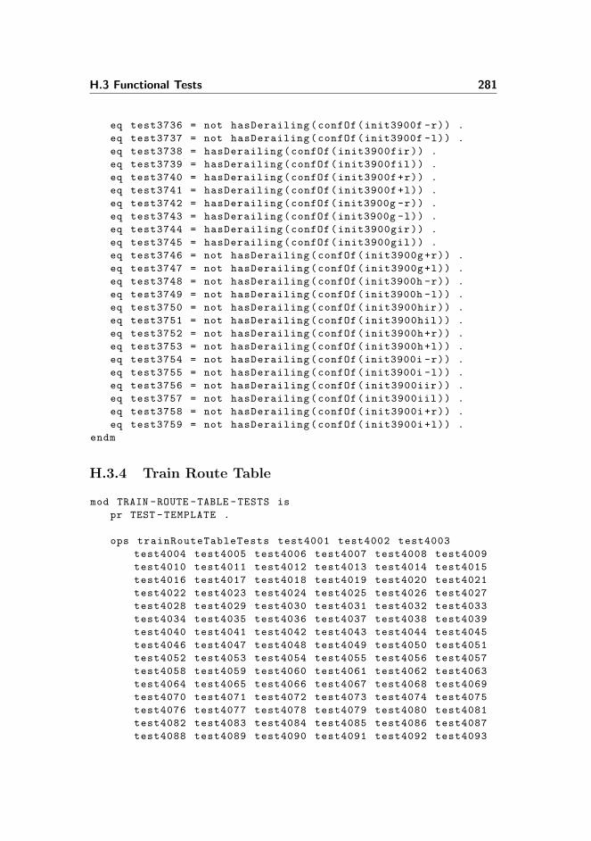
H.3 Functional Tests 281
eq test3736 = not hasDerailing(confOf(init3900f -r)) .
eq test3737 = not hasDerailing(confOf(init3900f -l)) .
eq test3738 = hasDerailing(confOf(init3900fir)) .
eq test3739 = hasDerailing(confOf(init3900fil)) .
eq test3740 = hasDerailing(confOf(init3900f+r)) .
eq test3741 = hasDerailing(confOf(init3900f+l)) .
eq test3742 = hasDerailing(confOf(init3900g -r)) .
eq test3743 = hasDerailing(confOf(init3900g -l)) .
eq test3744 = hasDerailing(confOf(init3900gir)) .
eq test3745 = hasDerailing(confOf(init3900gil)) .
eq test3746 = not hasDerailing(confOf(init3900g+r)) .
eq test3747 = not hasDerailing(confOf(init3900g+l)) .
eq test3748 = not hasDerailing(confOf(init3900h -r)) .
eq test3749 = not hasDerailing(confOf(init3900h -l)) .
eq test3750 = not hasDerailing(confOf(init3900hir)) .
eq test3751 = not hasDerailing(confOf(init3900hil)) .
eq test3752 = not hasDerailing(confOf(init3900h+r)) .
eq test3753 = not hasDerailing(confOf(init3900h+l)) .
eq test3754 = not hasDerailing(confOf(init3900i -r)) .
eq test3755 = not hasDerailing(confOf(init3900i -l)) .
eq test3756 = not hasDerailing(confOf(init3900iir)) .
eq test3757 = not hasDerailing(confOf(init3900iil)) .
eq test3758 = not hasDerailing(confOf(init3900i+r)) .
eq test3759 = not hasDerailing(confOf(init3900i+l)) .
endm
H.3.4 Train Route Table
mod TRAIN -ROUTE -TABLE -TESTS is
pr TEST -TEMPLATE .
ops trainRouteTableTests test4001 test4002 test4003
test4004 test4005 test4006 test4007 test4008 test4009
test4010 test4011 test4012 test4013 test4014 test4015
test4016 test4017 test4018 test4019 test4020 test4021
test4022 test4023 test4024 test4025 test4026 test4027
test4028 test4029 test4030 test4031 test4032 test4033
test4034 test4035 test4036 test4037 test4038 test4039
test4040 test4041 test4042 test4043 test4044 test4045
test4046 test4047 test4048 test4049 test4050 test4051
test4052 test4053 test4054 test4055 test4056 test4057
test4058 test4059 test4060 test4061 test4062 test4063
test4064 test4065 test4066 test4067 test4068 test4069
test4070 test4071 test4072 test4073 test4074 test4075
test4076 test4077 test4078 test4079 test4080 test4081
test4082 test4083 test4084 test4085 test4086 test4087
test4088 test4089 test4090 test4091 test4092 test4093

282 Test
test4094 test4095 test4096 test4097 test4098 test4099
test4100 test4101 test4102 test4103 test4104 test4105
test4106 test4107 test4108 test4109 test4110 test4111
test4112 test4113 test4114 test4115 test4116 test4117
test4118 test4119 test4120 test4121 test4122 test4123
test4124 : -> ModelCheckResult .
eq test4001 = not wfTrainRoute(’nonExisting , confOf(
init4101)) .
eq test4002 = not wfTrainRoute(’tr2 , confOf(init4101)) .
eq test4003 = conflictingExist ((’tr2), confOf(init4101))
.
eq test4004 = not trackSectionsExist ((’entryA , ’entryB ,
’01, ’02, ’03, ’A12 , ’B12), confOf(init4101)) .
eq test4005 = not trackSectionsExist(’entryA , confOf(
init4101)) .
eq test4006 = not signalsAndLampsExist (([’a x green], [’A
x green]), confOf(init4101)) .
eq test4007 = not wfTrainRoute(’nonExisting , confOf(
init4102)) .
eq test4008 = not wfTrainRoute(’tr2 , confOf(init4102)) .
eq test4009 = conflictingExist(’tr2 , confOf(init4102)) .
eq test4010 = not trackSectionsExist ((’entryA , ’entryB ,
’01, ’02, ’03, ’A12 , ’B12), confOf(init4102)) .
eq test4011 = trackSectionsExist(’entryA , confOf(init4102
)) .
eq test4012 = not signalsAndLampsExist (([’a x green], [’A
x green]), confOf(init4102)) .
eq test4013 = not wfTrainRoute(’nonExisting , confOf(
init4103)) .
eq test4014 = not wfTrainRoute(’tr2 , confOf(init4103)) .
eq test4015 = conflictingExist(’tr2 , confOf(init4103)) .
eq test4016 = not trackSectionsExist ((’entryA , ’entryB ,
’01, ’02, ’03, ’A12 , ’B12), confOf(init4103)) .
eq test4017 = trackSectionsExist ((’entryA , ’entryB),
confOf(init4103)) .
eq test4018 = not signalsAndLampsExist (([’a x green], [’A
x green]), confOf(init4103)) .
eq test4019 = signalsAndLampsExist ([’a x green], confOf(
init4103)) .
eq test4020 = not wfTrainRoute(’nonExisting , confOf(
init4104)) .
eq test4021 = not wfTrainRoute(’tr2 , confOf(init4104)) .
eq test4022 = conflictingExist(’tr2 , confOf(init4104)) .
eq test4023 = not trackSectionsExist ((’entryA , ’entryB ,
’01, ’02, ’03, ’A12 , ’B12), confOf(init4104)) .

H.3 Functional Tests 283
eq test4024 = trackSectionsExist ((’entryA , ’entryB),
confOf(init4104)) .
eq test4025 = signalsAndLampsExist ([’a x green], confOf(
init4104)) .
eq test4026 = not signalsAndLampsExist ([’A x green],
confOf(init4104)) .
eq test4027 = not wfTrainRoute(’nonExisting , confOf(
init4105)) .
eq test4028 = not wfTrainRoute(’tr2 , confOf(init4105)) .
eq test4029 = conflictingExist(’tr2 , confOf(init4105)) .
eq test4030 = not trackSectionsExist ((’entryA , ’entryB ,
’01, ’02, ’03, ’A12 , ’B12), confOf(init4105)) .
eq test4031 = trackSectionsExist ((’entryA , ’entryB),
confOf(init4105)) .
eq test4032 = signalsAndLampsExist (([’a x green], [’A x
green]), confOf(init4105)) .
eq test4033 = not wfTrainRoute(’nonExisting , confOf(
init4106)) .
eq test4034 = not wfTrainRoute(’tr2 , confOf(init4106)) .
eq test4035 = conflictingExist(’tr2 , confOf(init4106)) .
eq test4036 = not trackSectionsExist ((’entryA , ’entryB ,
’01, ’02, ’03, ’A12 , ’B12), confOf(init4106)) .
eq test4037 = trackSectionsExist ((’entryA , ’entryB , ’01,
’03), confOf(init4106)) .
eq test4038 = signalsAndLampsExist (([’a x green], [’A x
green]), confOf(init4106)) .
eq test4039 = trackSectionsExist ((’01, ’03), confOf(
init4106)) .
eq test4040 = not wfTrainRoute(’nonExisting , confOf(
init4106)) .
eq test4041 = wfTrainRoute(’tr2 , confOf(init4107)) .
eq test4042 = conflictingExist(’tr2 , confOf(init4107)) .
eq test4043 = trackSectionsExist ((’entryA , ’entryB , ’01,
’02, ’03, ’A12 , ’B12), confOf(init4107)) .
eq test4044 = conflictingExist(’tr2 , confOf(init4107)) .
eq test4045 = signalsAndLampsExist (([’a x green], [’A x
green]), confOf(init4107)) .
eq test4046 = trackSectionsExist ((’01, ’03), confOf(
init4107)) .
eq test4047 = not wfTrainRoute(’nonExisting , confOf(
init4108)) .
eq test4048 = wfTrainRoute(’tr2 , confOf(init4108)) .
eq test4049 = not wfTrainRoute(’tr3 , confOf(init4108)) .
eq test4050 = conflictingExist(’tr2 , confOf(init4108)) .
eq test4051 = conflictingExist(’tr3 , confOf(init4108)) .
eq test4052 = trackSectionsExist ((’entryA , ’entryB , ’01,
’02, ’03, ’A12 , ’B12), confOf(init4108)) .

284 Test
eq test4053 = trackSectionsExist ((’entryA , ’entryB , ’01,
’03), confOf(init4108)) .
eq test4054 = signalsAndLampsExist (([’a x green], [’A x
green]), confOf(init4108)) .
eq test4055 = trackSectionsExist ((’01, ’03), confOf(
init4108)) .
eq test4056 = not conflictingExist(’nonExisting , confOf(
init4108)) .
*** Conflicting is well formed
eq test4060 = conflIsConfl(’tr2 , (’tr2 , ’tr3), confOf(
init4109)) .
eq test4061 = conflIsConfl(’tr3 , (’tr3 , ’tr9), confOf(
init4109)) .
eq test4062 = not conflIsConfl(’tr31 , ’tr9 , confOf(
init4109)) .
eq test4063 = mutuallyConfl(’tr2 , (’tr2 , ’tr3), confOf(
init4109)) .
eq test4064 = mutuallyConfl(’tr3 , (’tr3 , ’tr9), confOf(
init4109)) .
eq test4065 = not mutuallyConfl(’tr30 , (’tr9), confOf(
init4109)) .
eq test4066 = wfConflicting(’tr2 , (’tr2 , ’tr3), confOf(
init4109)) .
eq test4067 = wfConflicting(’tr3 , (’tr2 , ’tr3 , ’tr9),
confOf(init4109)) .
eq test4068 = wfConflicting(’tr9 , (’tr3 , ’tr9), confOf(
init4109)) .
eq test4069 = not wfConflicting(’tr30 , (’tr9 , ’tr30 , ’
tr31), confOf(init4109)) .
eq test4070 = not wfConflicting(’tr31 , (’tr30 , ’tr31),
confOf(init4109)) .
*** Points are well formed
eq test4071 = uniquePosition (([’p1 in plus], [’p2 in
minus], [’p3 in plus], [’p4 in minus]), empty) .
eq test4072 = uniquePosition (([’p1 in plus], [’p2 in
minus], [’p3 in plus], [’p1 in plus]), empty) .
eq test4073 = not uniquePosition (([’p1 in plus], [’p2 in
minus], [’p3 in plus], [’p1 in minus]), empty) .
eq test4074 = wfRoute(’tr2 , confOf(init4110)) .
eq test4075 = not wfRoute(’tr3 , confOf(init4110)) .
eq test4076 = not wfRoute(’tr4 , confOf(init4110)) .
eq test4077 = wfPoints (([’01 in plus], [’03 in minus]),
(’entryA , ’entryB , ’01, ’02, ’03, ’A12 , ’B12), confOf(
init4110)) .
eq test4078 = not wfPoints (([’01 in minus], [’01 in plus
]), (’entryA , ’entryB , ’01, ’02, ’03, ’A12 , ’B12),
confOf(init4110)) .

H.3 Functional Tests 285
*** Route is well formed
eq test4079 = wfRoute(’tr1 , confOf(init4111)) .
eq test4080 = not wfRoute(’tr2 , confOf(init4111)) .
eq test4081 = wfRoute(’tr3 , confOf(init4111)) .
eq test4082 = wfRoute(’tr4 , confOf(init4111)) .
eq test4083 = not wfRoute(’tr5 , confOf(init4111)) .
*** The locking pair is well formed
eq test4084 = not wfLocking(’tr1 , confOf(init4111)) .
eq test4085 = wfLocking(’tr2 , confOf(init4111)) .
eq test4086 = not wfLocking(’tr3 , confOf(init4111)) .
eq test4087 = not wfLocking(’tr4 , confOf(init4111)) .
eq test4088 = wfLocking(’tr6 , confOf(init4111)) .
*** Deduce signal that should stop displaying green when
track section from "Stop fald" is occupied
eq test4089 = getStopSignal(’tr2 , confOf(init4120)) == ’A
.
eq test4090 = getStopSignal(’tr3 , confOf(init4120)) == ’A
.
eq test4091 = getStopSignal(’tr5 , confOf(init4120)) == ’B
.
eq test4092 = getStopSignal(’tr6 , confOf(init4120)) == ’B
.
eq test4093 = getStopSignal(’tr7 , confOf(init4120)) == ’E
.
eq test4094 = getStopSignal(’tr8 , confOf(init4120)) == ’F
.
eq test4095 = getStopSignal(’tr9 , confOf(init4120)) == ’G
.
eq test4096 = getStopSignal(’tr10 , confOf(init4120)) == ’
H .
*** Stenstrup train route table overall
eq test4097 = not relaysExist(’IAdub -470, confOf(init4101
)) .
eq test4098 = relaysExist(’IAdub -470, confOf(init4120)) .
eq test4099 = wfTrainRoute(’tr5 , confOf(init4120)) .
eq test4100 = wfTrainRouteTable(confOf(init4120)) .
*** Stenstrup circuit , track layout and train route table
overall
eq test4101 = wfTrainRouteTable(confOf(initStenstrup)) .
*** eq test4102 = allSafetyProperties(confOf(
initStenstrup)) .
eq test4103 = wfTrainRoute(’tr9 , confOf(initStenstrup)) .
eq test4104 = wfTrainRoute(’tr10 , confOf(initStenstrup))
.
eq test4105 = wfTrainRouteTable(confOf(init -stenstrup -
extended -trt)) . *** false

286 Test
eq test4106 = relaysExist(’IAdub -470, confOf(init -
stenstrup -extended -trt)) .
eq test4107 = isSteelCoreRelay(’IAdub -470, confOf(init -
stenstrup -extended -trt)) .
eq test4108 = inRoute(’tr7 , confOf(init -stenstrup -
extended -trt)) .
eq test4109 = trackSectionsExist(’tr7 , confOf(init -
stenstrup -extended -trt)) .
eq test4110 = signalsAndLampsExist( ([’E x green], [’F x
red]), confOf(init -stenstrup -extended -trt)) .
eq test4111 = wfConflicting(’tr7 , confOf(init -stenstrup -
extended -trt)) .
eq test4112 = wfPoints(’tr7 , confOf(init -stenstrup -
extended -trt)) .
eq test4113 = wfRoute(’tr7 , confOf(init -stenstrup -
extended -trt)) .
eq test4114 = wfLocking(’tr7 , confOf(init -stenstrup -
extended -trt)) .
eq test4115 = wfTrainRoute(’tr2 , confOf(init -stenstrup -
extended -trt)) .
eq test4116 = wfTrainRoute(’tr3 , confOf(init -stenstrup -
extended -trt)) .
eq test4117 = wfTrainRoute(’tr5 , confOf(init -stenstrup -
extended -trt)) .
eq test4118 = wfTrainRoute(’tr6 , confOf(init -stenstrup -
extended -trt)) .
eq test4119 = wfTrainRoute(’tr7 , confOf(init -stenstrup -
extended -trt)) . *** false
eq test4120 = wfTrainRoute(’tr8 , confOf(init -stenstrup -
extended -trt)) . *** false
eq test4121 = wfTrainRoute(’tr9 , confOf(init -stenstrup -
extended -trt)) . *** false
eq test4122 = wfTrainRoute(’tr10 , confOf(init -stenstrup -
extended -trt)) . *** false
eq test4123 = wfDisplayStop(’tr7 , confOf(init -stenstrup -
extended -trt)) . *** false
eq test4124 = wfIds(confOf(init -stenstrup -extended -trt))
.
endm

Appendix I
CD Content
A CD with material was enclosed with this report. This section will provide anoverview of the content on the CD by describing the content of each folder inthe root of the CD.
I.1 /auxilliaryTools
This folder contains all the JAR files to the auxiliary tools developed in thisproject, see chapter 8 for a description of the tools or appendix K for a manualon how to use the tools. Unfortunately, only the extended Simulator has beenupdated to support the final version of the specified model. The reasons for thisis explained in section 7.6.3.
I.2 /maudeModules
This folder contains all the Maude modules and files that define the model ofan interlocking system developed in this project. The modules are split into fivesub folders:

288 CD Content
/maudeModules/circuit contains the modules specifying the circuit.
/maudeModules/trackLayout contains the modules specifying the tracklayout.
/maudeModules/train contains the modules specifying the train.
/maudeModules/trainRouteTable contains the modules specifying the trainroute table.
/maudeModules/verification contains the modules and other files used forverification of the model.
I.3 /report
This folder contains two PDF-files of the report. One for printing and onecontaining hyperlinks for easier navigation while reading the report.
I.4 /stenstrup
This folder contains all files associated with Stenstrup station. The sub foldersare:
/stenstrup/baneDanmark contains scanned TIF files of the paper docu-mentation from BaneDanmark.
/stenstrup/extendedSimulator contains the .ris file specifying the inter-locking system at Stenstrup station. In relation to the .ris file made in [5]the new .ris file contains additional diagrams from Stenstrup station andthe additional information for this project describing signals, track sectionlengths and train routes.
/stenstrup/maude contains the .maude file specifying the interlocking sys-tem at Stenstrup station.
I.5 /test
This folder contains the test interlocking systems which have been used to testthe model. The tests are split into the four main areas of the domain:

I.6 /verification 289
/test/circuit contains the .ris and .maude files for the interlocking systemsmade for testing the circuit.
/test/trackLayout contains the .ris and .maude files for the interlocking sys-tems made for testing the track layout.
/test/train contains the .ris and .maude files for the interlocking systemsmade for testing the train.
/test/trainRouteTable contains the .ris and .maude files for the interlockingsystems made for testing the train route table.
I.6 /verification
This folder contains all the verification output, as mentioned in section 7.6.

290 CD Content

Appendix J
Designing and Verifying anInterlocking System
In this section the process of designing and verifying an interlocking systemusing the tool created in [5] and this project will be described.
J.1 Designing an Interlocking System
In this section it will be described how an interlocking system is designed. Byfollowing the steps described below an interlocking system will be designed inthe extended Simulator tool and the design will be saved in a .ris file. The .risfile can be opened and edited in the extended Simulator at any time. When theinterlocking system has been designed it can be exported as a Maude module.
The next section will describe how this Maude module is used in the process ofverifying the designed interlocking system.
1. Run the extended Simulator application by navigating to the folder /aux-illiaryTools on the CD and run the JAR file.

292 Designing and Verifying an Interlocking System
2. Design an interlocking system. Information on how this tool is used canbe found in appendix K.1 and [5].
3. Export the designed interlocking system to a .maude file.
J.2 Verifying an Interlocking System
In this section it will be described how, given a Maude file specifying the ini-tial state of an interlocking system configuration, the model of the interlockingsystem will be verified.
1. Copy the Maude files developed in this project to a folder on your com-puter.
2. Run MaudeSee appendix B for how to install and run Maude.
3. Navigate to the folder which the Maude files where copied to.
4. Load the specified Maude module by executing the following command inMaude:load verify.maude
See sections 3 and B.2 for more details on how to interact with Maude.
As mentioned in section 7.6 the Kripke structure of the model for Stenstrupstation is currently too big to verify whether a given formula satisfies the model.If the test is run an error message will eventually be displayed, indicating thatMaude has run out of memory. If the verification terminates though, the resultswill be written to the Maude console as described e.g. in section H.1.

Appendix K
Manuals for Auxiliary Tools
This appendix provides manuals for the most important auxiliary tools imple-mented as part of this project, i.e. the extended Simulator originally developedin [5] and the Tester.
K.1 Extended Simulator
The report [5] provides a manual for how to use the basic functionality of thistool, e.g. how to create relay, add contacts to a diagram, connect components,push buttons and switch points. The help menu in the extended Simulator alsocontains a user’s guide explaining most of the functionality. The rest of thissection provides a brief manual on which extensions have been made and howthe remaining parts of an interlocking system can be defined in the application.Note that the focus of this extension of the Simulator has been on providing atool for automating the specification of an interlocking system in Maude. Theusability has thus not been given the pride of place.
For each lamp it must be defined which colour it has such that it can be deter-mined which aspect a given signal displays. For this to be possible the specificcolour must be specified. By right clicking the lamp component in the diagram

294 Manuals for Auxiliary Tools
and choosing Properties a dialog containing a text field opens. The chosencolour of the lamp should be specified in this text field as in figure K.1.
Figure K.1: Lamps must be specified to have one of three possible colours: “green”,“yellow” or “red”. The name of the colour must be specified in the properties of thelamp, by right clicking the component and choosing “Properties”.
The track layout in the original Simulator does not provide the option to specifythe signals guarding the different track sections. Figure K.2 shows an exampleof how signals signal2 and signal3 are specified for point 01. On linear tracksections signal1 is placed to the left on the track section and signal2 is placedto the right, see figure 5.5 on page 74. On points, signal1 is at the stem, signal2is at the plus position of the point (to the right when entering the point fromthe stem) and signal3 is at the minus position of the point (to the left, whenentering the point from the stem), see figure 5.6. Along with every signal, anid of the signal must be specified as well as which lamps the signal consists of.In the figure, signal2 has the id E and two lamps, Eroe and Egr. In the samefield the length of a track section can be specified. If e.g. the length of a tracksection should be 20 meters it is specified by writing length=20. If no length isspecified as in figure K.2 the length of the track section is set to 30.
The next (and probably most important) addition in the extended Simulatoris the ability to specify train routes for a given station. Figure K.3 shows howthe interface for specifying this information looks. The upper-most text fieldis used to specify which (if any) track sections are platforms on the station.The next text field allows the user to specify lengths of the trains allowed to

K.1 Extended Simulator 295
Figure K.2: By right clicking a track section in the track layout, it is possible to specifyan id of the signal and which signals (and lamps of each signal) should be associatedwith the given track section.
Figure K.3: This dialog is access by clicking the “TL & TRT” button in the toolbar.The dialog allows the user to specify the platforms of the system, the allowed lengthsof train on this station and the train routes of the station. More information on howto specify this information can be found by clicking the “Help” buttons.
enter this station, and finally, the bottom text field is used for specifying trainroutes of a train route table. Each line in this field corresponds to a single trainroute. The three Help buttons provide more information on the syntax used inthese fields and in which order the information must be specified to be valid and

296 Manuals for Auxiliary Tools
understandable for the Simulator. This dialog is opened by clicking the TL &TRT button on the toolbar in top of the Simulator window.
The final addition to this extended Simulator is the option to export the project(diagrams, track layout, train route table, etc.) to Maude. Figure K.4 showshow this is done. When the project is exported to Maude, the Simulator createsa .maude file containing a module with the objects of the specified interlockingsystem. Each component in the Simulator and the state of the component is
Figure K.4: When the interlocking system has been designed in the extended Simulator,it can be exported to a .maude file specifying the model.
exported to the file as the initial state of the system. Note, that if the systemis in the normal state in the Simulator when exporting, the initial state of thesystem in the Maude file reflects this state, i.e. the normal state of the system.
K.2 Tester
Another very useful tool is the Tester, explained in section 8.2. Figure K.5 showshow this application looks. The text field Model files is used to specify the filescontaining the model to test, i.e. the files to load into Maude before running thetests. Test files is used to specify the files containing the tests to be run on themodel. When these files have been specified the tests can be loaded into theapplication by clicking the Load tests button. In order for the application to beable to extract the tests from the test files, each test must be specified in the

K.2 Tester 297
Figure K.5: The “Tester” application provides a framework for running multiple se-quential tests on a model and have the results presented in a structured way.
following way:eq test 〈No〉 = 〈Query〉 .
〈No〉 must be a unique number identifying the specific test, and 〈Query〉 is theactual test that should be fed to Maude. When running the tests, the Testerfeeds Maude with this command:
reduce 〈Query〉 .
Before the tests are executed it is possible to select or deselect tests such thatonly the tests of interest at the time are run. When this is done, the Run testsbutton is clicked and the tests are fed to Maude “behind the scenes”. As Maudefinishes the individual tests, the colour of the associates test changes to green orred depending on whether the test returned true (for success) or anything else(interpreted as a failure). The Show button gets activated and by clicking this,the text fields on the Results tab get updated with the results of this specific

298 Manuals for Auxiliary Tools
test. The Results tab provides the options to have the output of Maude tobe formatted in different ways, e.g. display the raw output, format the outputby applying line breaks/tabs and finally, the Tester can analyse the output andonly display the rules applied by Maude and specify which objects have changedas a consequence of applying this rule.

Bibliography
[1] Marie Le Bliguet and Andreas A. Kjær. Modelling Interlocking Systemsfor Railway Stations. Technical Report IMM-M.Sc.-2008-68, Informaticsand Mathematical Modelling, Technical University of Denmark, RichardPetersens Plads, Building 321, DK-2800 Kgs. Lyngby, 2008. Master thesissupervised by Anne Haxthausen.
[2] Jouannaud J.-P. Meseguer J. Bouhoula, A. Specification and proof in mem-bership equational logic, 35-132. Theoretical Computer Science 236, 2000.
[3] Manuel Clavel, Francisco Duran, Steven Eker, Patrick Lincoln, NarcisoMartı-Oliet, Jose Meseguer, and Carolyne Talcott. All About Maude - AHigh-Performance Logical Framework. Lecture Notes in Computer Science.Springer, 2007.
[4] Razvan Diaconescu and Kokichi Futatsugi. CafeOBJ Report : The Lan-guage, Proof Techniques, and Methodologies for Object-Oriented AlgebraicSpecification. Amast Series in Computing. World Scientific Publishing,1998.
[5] Louise E. Eriksen and Boe Pedersen. Simulation of Relay Interlocking Sys-tems. Technical Report IMM-M.Sc.-2007-04, Informatics and Mathemati-cal Modelling, Technical University of Denmark, Richard Petersens Plads,Building 321, DK-2800 Kgs. Lyngby, 2007. Bachelor thesis supervised byAnne Haxthausen and Hubert Baumeister.
[6] Kokichi Futatsugi et al. Cafeobj user’s manual, version 1.4.
[7] Valentin Goranko. Lecture notes on temporal logics for specification andverification, 2009.

300 BIBLIOGRAPHY
[8] RAISE Tool User Guide.http://www.iist.unu.edu/newrh/III/3/1/docs/rsltc/user_guide/
html/ug_0.html.
[9] Anne E. Haxthausen. A Domain-specific Framework for Automated Con-struction and Verification of Railway Control Systems. In B. Buth, G. Rabe,and T. Seyfarth, editors, Proceedings of 28th International Conference onComputer Safety, Reliability, and Security, SAFECOMP 2009, number5775 in Lecture Notes in Computer Science, pages 1–3. Springer, 2009.Invited paper.
[10] Anne E. Haxthausen. Developing a Domain Model for Relay Circuits.International Journal of Software and Informatics, 3(2–3):241–272, 2009.
[11] Anne E. Haxthausen, Nikolaj Christensen, and Rasmus Dyhrberg. FromDomain Model to Domain-specific Language for Railway Control Systems.In Proceedings of Formal Methods for Automation and Safety in Railwayand Automotive Systems (FORMS/FORMAT 2004)), Braunschweig, Ger-many, 2004.
[12] Anne E. Haxthausen and Jan Peleska. A Domain-oriented, Model-basedApproach for Construction and Verification of Railway Control Systems.In Cliff B. Jones, Zhiming Liu, and Jim Woodcock, editors, Formal Meth-ods and Hybrid Real-Time Systems : Essays in Honour of Dines Bjørnerand Zhou Chaochen on Occasion of their 70th Birthdays, number 4700 inLecture Notes in Computer Science, pages 320–348. Springer, 2007. Invitedpaper.
[13] Anne E. Haxthausen, Jan Peleska, and Sebastian Kinder. A Formal Ap-proach for the Construction and Verification of Railway Control Systems.Formal Aspects of Computing, online first 2009. Special issue in Honour ofDines Bjørner and Zhou Chaochen on Occasion of their 70th Birthdays.
[14] Keijo Heljanko. Lecture slides from universitat stuttgart on KripkeStructures and Automatahttp://www.fmi.uni-stuttgart.de/szs/teaching/ws0304/nets/
slides7.pdf, 2003.
[15] Holger Hermanns. Interactive Markov chains: and the quest for quantifiedquality. Springer, 2002.
[16] CafeOBJ homepage.http://cseweb.ucsd.edu/~goguen/sys/obj.html#CafeOBJ.
[17] Official homepage of the OBJ Family languages.http://cseweb.ucsd.edu/~goguen/sys/obj.html.
BIBLIOGRAPHY 301
[18] Miguel Palomino Jose Meseguer and Narciso Martı-Oliet. Equational ab-stractions, 2008.
[19] Timo Lepisto and Arto Salomaa. Automata, Languages and Programming:15th International Colloquium, Tampere, Finland. Springer, 1988.
[20] Theodore McCombs. Maude 2.0 Primer. 2003.
[21] Langley Formal Methods NASA.http://shemesh.larc.nasa.gov/fm/fm-what.html.
[22] Kazuhiro Ogata. Proof score writing for qlock in ots/cafeobj, 2010. LectureNote 05b, CafeOBJ Team for JAIST-FSSV2010.
[23] Jan Peleska, Daniel Große, Anne E. Haxthausen, and Rolf Drechsler. Au-tomated Verification for Train Control Systems. In Proceedings of FormalMethods for Automation and Safety in Railway and Automotive Systems(FORMS/FORMAT 2004)), Braunschweig, Germany, 2004.
[24] Jan Peleska and Anne E. Haxthausen. Object Code Verification for Safety-Critical Railway Control Systems. In Proceedings of Formal Methods forAutomation and Safety in Railway and Automotive Systems (FORMS/-FORMAT 2007), Braunschweig, Germany. GZVB e.V., 2007. ISBN 13:978-3-937655-09-3.
[25] The RAISE Language Group. The RAISE Specification Language. TheBCS Practitioners Series. Prentice Hall Int., 1992.
[26] Wolfram Research.http://mathworld.wolfram.com/TermRewritingSystem.html.
[27] Wikipedia.org: Term rewriting.http://en.wikipedia.org/wiki/Term_rewriting.