verisketch: synthesizing secure hardware designs with ... · verisketch: synthesizing secure...
TRANSCRIPT
VeriSketch: Synthesizing Secure Hardware Designs withTiming-Sensitive Information Flow PropertiesArmaiti Ardeshiricham
University of California, San [email protected]
Yoshiki TakashimaUniversity of California, San Diego
Sicun GaoUniversity of California, San Diego
Ryan KastnerUniversity of California, San Diego
ABSTRACTWepresent VeriSketch, a security-oriented program synthesis frame-work for developing hardware designs with formal guarantee offunctional and security specifications. VeriSketch defines a synthe-sis language, a code instrumentation framework for specifying andinferring timing-sensitive information flow properties, and uses spe-cialized constraint-based synthesis for generating HDL code that en-forces the specifications. We show the power of VeriSketch throughsecurity-critical hardware design examples, including cache con-trollers, thread schedulers, and system-on-chip arbiters, with formalguarantee of security properties such as absence of timing side-channels, confidentiality, and isolation.
ACM Reference Format:Armaiti Ardeshiricham, Yoshiki Takashima, Sicun Gao, and Ryan Kastner.2019. VeriSketch: Synthesizing Secure Hardware Designs with Timing-Sensitive Information Flow Properties. In 2019 ACM SIGSAC Conference onComputer and Communications Security (CCS ’19), November 11–15, 2019,London, United Kingdom. ACM, New York, NY, USA, 16 pages. https://doi.org/10.1145/3319535.3354246
1 INTRODUCTIONThe prevalent way of designing digital circuits uses register-transferlevel (RTL) hardware description languages (HDLs). It requiresdesigners to fully specify micro-architectural features on a cycle-by-cycle basis. The verbosity and complexity of RTL HDLs opensthe door for security vulnerabilities. With the growing number andseverity of hardware security-related attacks [11, 16, 28, 31], weurgently need better tools for detecting and mitigating securityvulnerabilities for hardware designs.
We propose the VeriSketch program synthesis framework fordeveloping secure-by-construction hardware designs. VeriSketchfrees hardware designers from exactly specifying cycle-by-cyclebehaviors. Instead, the designer provides an RTL sketch, a set ofsecurity and functional specifications, and an optional set of softconstraints. VeriSketch outputs complete Verilog programs that
Permission to make digital or hard copies of all or part of this work for personal orclassroom use is granted without fee provided that copies are not made or distributedfor profit or commercial advantage and that copies bear this notice and the full citationon the first page. Copyrights for components of this work owned by others than ACMmust be honored. Abstracting with credit is permitted. To copy otherwise, or republish,to post on servers or to redistribute to lists, requires prior specific permission and/or afee. Request permissions from [email protected] ’19, November 11–15, 2019, London, United Kingdom© 2019 Association for Computing Machinery.ACM ISBN 978-1-4503-6747-9/19/11. . . $15.00https://doi.org/10.1145/3319535.3354246
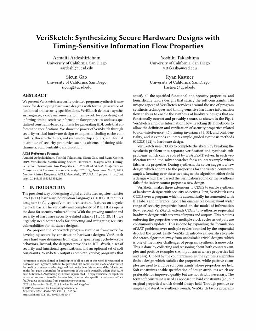
satisfy all the specified functional and security properties, andheuristically favors designs that satisfy the soft constraints. Theunique aspect of VeriSketch revolves around the use of programsynthesis techniques and timing-sensitive hardware informationflow analysis to enable the synthesis of hardware designs that arefunctionally correct and provably secure, as shown in the Fig. 1.VeriSketch employs Information Flow Tracking (IFT) methods toallow the definition and verification of security properties relatedto non-interference [46], timing invariance [3, 53], and confiden-tiality, and it extends counterexample-guided synthesis methods(CEGIS) [42] to hardware design.
VeriSketch uses CEGIS to complete the sketch by breaking thesynthesis problem into separate verification and synthesis sub-problems which can be solved by a SAT/SMT solver. In each ver-ification round, the solver searches for a counterexample whichfalsifies the properties. During synthesis, the solver suggests a newdesign which adheres to the properties for the visited counterex-amples. Iterating over these two stages, the algorithm either findsa design which has passed the verification round or the synthesisfails if the solver cannot propose a new design.
VeriSketch makes three extensions to CEGIS to enable synthesisof hardware designs with security objectives. First, VeriSketch runsCEGIS over a program which is automatically instrumented withIFT labels and inference logic. This enables reasoning about widerrange of security properties based on the model of informationflow. Second, VeriSketch extends CEGIS to synthesize sequentialhardware designs with streams of inputs and outputs. This requiresenforcing the properties over multiple clock cycles as outputs arecontinuously updated. This is done by expanding the formulationof SAT problems over multiple cycles bounded by the sequentialdepth of the circuit. Lastly, VeriSketch introduces heuristics to guidethe search algorithm away from undesirable trivial designs, whichis one of the major challenges of program synthesis frameworks.This is done by collecting and reasoning about both counterexam-ples and positive examples (i.e., input traces where properties failand pass). Guided by the counterexamples, the synthesis algorithmfinds a design which satisfies the properties, while positive exam-ples are used to enforce soft constraints where properties are held.Soft constraints enable specification of design attributes which arepreferable for improved quality but are not strictly necessary. Theterm soft constraint is used as opposed to hard constraints (i.e., ouroriginal properties) which should always hold. Through positive ex-amples and iterative synthesis rounds, VeriSketch favors programs
Exploration
Synthesis
Verification
SMT Solver
1) Sketch and Specification 2) Instrumentation 3) Program Synthesis 4) Secure and Correct Hardware DesignSketch: Incomplete Verilog Design Verilog Instrumented with Security Labels Constraint-based Synthesis (CEGIS) Verified Verilog
SAT
if(pid == i && preload[addr]) assume (index_s == High);
if(pid != i) assert (rd_dat_proc == Low);
try (!skip && lru_update);
Functional and Security Properties, and Soft Constraints
Modify Sketch and/or Properties UN
SAT
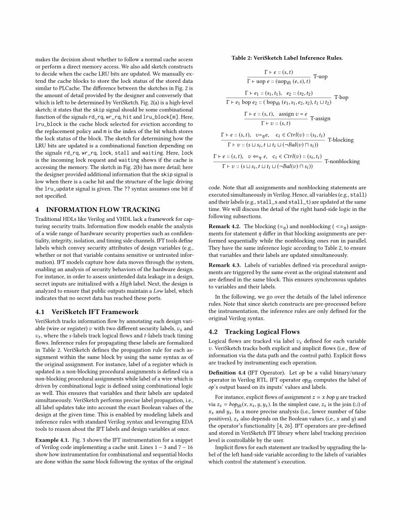
Figure 1: VeriSketch accepts as input an incomplete hardware design (i.e., a “sketch”) and a set of functional and securityproperties and soft constraints. VeriSketch leverages hardware information flow tracking and program synthesis to build aVerilog design that satisfies the properties.
where soft constraints are held without changing the satisfiabilityof the synthesis problem.
We use VeriSketch to generate hardware units that adhere tovarious properties from sketches with different levels of detailsspelled out by the programmer. We synthesize a cache controllerwhich is provably resilient against access-based timing side channelattacks. We design fixed point arithmetic units such that they areproven to run in constant time. Furthermore, we generate multipleSoC arbiters and hardware thread schedulers that enforce non-interference, timing predictability, and access control policies.
In all, we make the following contributions and organize thepaper as follows. We introduce the VeriSketch framework for semi-automated synthesis of RTL hardware designs that enforce timing-sensitive information flow policies. Section 3 introduces the for-mal language definitions and main components of VeriSketch ata high-level. Next, we demonstrate how IFT analysis can be usedto complete information flow constraints in Section 4. Section 5focuses on introducing new program synthesis techniques that ex-tend CEGIS for the synthesis based on information flow properties,sequential circuits with bounded depth, and soft constraints. Wediscuss the synthesized designs in Section 6.
2 BACKGROUND AND RELATEDWORKVeriSketch adopts and extends techniques from program synthesisand repair, as well as hardware information flow tracking systems.Here, we briefly review the related work in each of these domains.
2.1 Program SynthesisConstraint-based synthesis is modeled as ∃p∀x . ϕ(x ,p) where ϕdenotes the design and specification, x is the design inputs and pis the synthesis parameter encoding the undefined portion of thedesign. The synthesizer’s goal is to find parameter p such that theproperties in ϕ are satisfied for all inputs x . CEGIS [2, 42, 43] intro-duces a method for breaking down the exists-forall quantificationto iterations between verification and synthesis procedures that canbe solved by SAT/SMT solvers. The verification phase at each roundi fixes the parameter p to pi and attempts to verify the universalconditions on all input combinations. The verification problemcan be written as ∃x . ¬ϕ(x , pi ), which asks the solver to find a
case where properties are violated for the program synthesized byparameter pi . Unsatisfiability here indicates that properties holdsfor all input cases. Thus, pi is a valid solution and the synthesisflow ends successfully. If satisfiable, the solver provides a coun-terexample xi which falsifies the properties. The synthesis stagelooks for a new parameter that satisfies the properties for all thepreviously visited counterexamples. This problem in round i canbe modeled as: ∃p. ∧x j ∈ CE ϕ(x j , p), whereCE is the set of visitedcounterexamples. If the solver fails to find a solution, the synthesisflow terminates unsuccessfully indicating that the properties areunsatisfiable for the given sketch.
Synthesis techniques are widely used to automate difficult soft-ware engineering tasks [17, 22, 27, 37, 43]. Program synthesis havebeen employed in different domains such as data processing [41, 51],data completion [18, 47], databases [52, 54], and more recently insecurity applications [24, 38]. In the HDL domain, Sketchilog [6, 7]translates partially written Verilog code to complete ones by di-rectly solving the exists-forall problem employing a QBF solver.Sketchilog can only synthesize small combinatorial circuits, andis not scalable due to the limitations of QBF solvers. Furthermore,Sketchilog does not support expressive properties as high levelspecifications. VeriSketch extends CEGIS to enable synthesis ofcombinational and sequential circuits written in HDLs from highlevel specifications. Our problem statement is similar to that ofprogram repair techniques for automatically generating patchesfor security-critical programs [20, 21, 23, 44]. Our work is uniquefrom these previous works because we enforce security and func-tional properties while synthesizing incomplete hardware designs.Counterexample guided algorithms have been used to automaticallysynthesize device drivers [39, 40] and generate abstraction modelsfor SoCs [45] and ISAs [25]. Similar techniques have been used atthe gate level to automatically modify a netlist when errors aredetected late in the design flow [10, 50]. VeriSketch uses CEGIS ata higher level of abstraction to complete partial HDLs with respectto security properties and acquaint the traditional hardware designflow with automated policy enforcement.
2.2 Information Flow ControlVeriSketch leverages hardware-level information flow analysis toreason about security properties. Hardware IFT tools can be broadly
divided into two categories based on whether they introduce newHDLs enabling definition of security labels [29, 30, 53] or rely onautomated label inference rules [3, 4, 46]. Here, we take the lat-ter approach in order to enable integration of flow tracking withsketching and synthesis. The structure of common HDLs facilitateprecise analysis of information flow policies and detection of tim-ing leakage (refer to Remarks 4.8, 4.11 and 4.13). VeriSketch adoptsthe approach from Clepsydra [3] which provides a sound labelingsystem for precisely capturing timing flows in RTL designs andverifying timing invariance properties. We extend and formalizeClepsydra’s label inference rules and integrate them with programsynthesis techniques to automatically enforce timing-sensitive in-formation flow policies.
2.3 Motivating ExampleTo illustrate the challenges of secure hardware design, we takedesign of a cache that is resilient to timing side channel attack asan example, and show how it is done via the traditional hardwaredesign flow versus by using VeriSketch. Unfortunately, modifyinghardware designs according to security requirements is often nottrivial; even the foremost hardware security experts canmake errorsas we discuss in the following.
2.3.1 Threat Model. We consider the Percival attack model [36]where the adversary runs concurrently with the victim process ona Simultaneous Multi-Threading processor. The adversary is anunprivileged user process which is isolated from the victim process,i.e., it does not share the address space with the victim. The attackeraims to learn information about the addresses which the victim usesto access the cache. The attack relies on the fact that in certain RSAimplementations parts of the encryption key is used to look up a pre-computed table in the cache. Hence, by observing the cache accesspattern of the victim process, the adversary could gain knowledgeabout the key. While the Percival attack originally targeted theOpenSSL implementation of the RSA algorithm, similar attackscan target different applications where the cache index is drivenfrom secret data [28]. In order to launch the attack, the adversaryrepeatedly fills the cache with its own data and measures eachaccess time. Once the victim accesses some cache line, it evicts theattacker’s data from that line. This eviction increases the attacker’saccess time in the following round.
2.3.2 Traditional Secure Hardware Design Flow. Assume that thedesigners decide to implement the partition locked cache (PLCache)mitigation technique [53] to secure the cache against the describedattack model. PLCache enables processes to preload and lock sen-sitive data in the cache to avoid eviction and timing variations.It extends a “normal” cache controller with logic that arbitratesaccess to the cache based on the security requirements. As a proofof concept, we created a Verilog design of the PLCache based uponthe details in their paper. We instrumented it and verified it againstthe IFT properties modeling cache timing leakage (described inExample 4.17), and the security verification failed. Analyzing thecounterexample trace given by the verification tool, we discoveredthat the side channel manifests itself through the cache metadata re-lated to the cache replacement policy. PLCache uses a least recentlyused (LRU) policy even for the locked data: in case of a cache hit,
normal cache access is performed. This introduces a subtle timingside channel that can be exploited by extending the Percival attack(described in Section 6.3.1). This shows that even the foremost secu-rity experts can create mitigation strategies that have flaws that goundiscovered for more than a decade. And even worse, the designeris now stuck with developing a new strategy to fix this flaw. In thiswork, we show how we use VeriSketch to synthesize a cache whichis provably resilient against the described attack model.
3 THE VERISKETCH FRAMEWORKVeriSketch synthesizes incomplete hardware designs that adhereto the specified security and functional properties. It targets de-signs at the register transfer level (RTL) abstraction. RTL remainsthe prevalent way of specifying hardware designs and it has therequired information to precisely analyze timing-sensitive infor-mation flow properties and identify timing side channels. We firstgive an overview of the main components of VeriSketch and thendescribe the details of the language design.
3.1 Main ComponentsFig. 1 describes the VeriSketch framework, which converts an RTLsketch and a set of hard and soft constraints into a complete Verilogdesign. All inputs are written in the VeriSketch language, which ex-tends Verilog with sketch and IFT specification syntax (see Table 1).As we show in the rest of this section, the VeriSketch languagefacilitates the modeling of security properties and a partial descrip-tion of the hardware. The sketch is first translated to a Verilogdesign which contains synthesis parameters. The Verilog design isthen instrumented with IFT analysis logic. This step (discussed inSection 4) enables reasoning about security properties alongsidethe functional ones. The instrumented design is given to the syn-thesis engine (described in Section 5) which uses constraint-basedsynthesis to resolve the parameters. If the synthesis succeeds (i.e.,a parameter is found), the post-processor fills out the initial sketchbased on the parameters values and discards the IFT instrumenta-tion. Otherwise, the programmer has to repeat the process afterrelaxing the specifications or modifying the sketch.
3.2 VeriSketch LanguageVeriSketch extends the standard Verilog language [13] with sketchconstructs and security property specifications. The formal syntaxis shown in Table 1.
3.2.1 Sketch Syntax. Sketches are language constructs that facil-itate writing partial programs [43]. VeriSketch enables users todescribe a partial hardware design by combining low-level andhigh-level sketch constructs with the original Verilog syntax. Withlow-level sketches, the designer can define unknown n-bit con-stants (n(??)), operation select (e1 (bop1, . . . , bopm ) e2), operandselect (sel(e1, . . . , em )), or choose the value of a variable from anyof n previous cycles (step?(v,n)). To facilitate higher level sketch-ing, VeriSketch introduces hardware-specific sketch constructs fordescribing arbitrary combinational (y = comb(x1, . . . ,xm )) andsequential circuits (y = seq(x1, . . . , xm )) with inputs x1, . . . ,xm ,and procedural statements with unknown control flow (v ?= e0).The original Verilog language supports two types of assignments:continuous and procedural assignments. Continuous assignments
are specified by the keyword assign and are used to specify com-binational logic. Procedural assignments are only activated whenthey are triggered (e.g., by each rising edge of the clock signal)and are used to describe complex timing behaviour. Proceduralassignments can be either blocking (=) or non-blocking (<=) whichindicates if the statements are executed sequentially or in parallel.VeriSketch allows sketches of procedural assignments with un-specified control logic using the v ?= e0 [e1, ..., em ] syntax. Thisis synthesized to a blocking or non-blocking assignment where afunction of [e1, ..., em ] signals is used as the control logic. The listof control variables [e1, ..., em ] can be defined separately for eachstatement or for the whole design.
3.2.2 Pre-Processing. Sketch constructs are compiled to synthesisparameters in the pre-processing round. The unknown constantsare directly replaced by parameters. Operand and operation selectsare modeled as multiplexers where control lines are parameters.step?(v,n) is mapped to a shift-register where one of its n slotsis selected by a synthesis parameter. v ?= e0 [e1, . . . , em ] is trans-lated into a block where assignment of e0 to v is guarded withan unknown control signal defined by comb(e1, . . . , em ). The combconstruct is compiled to a Binary Decision Diagram (BDD) tem-plate where the nodes are the inputs to the comb function. Theleaves of the tree are replaced by synthesis parameters. Hence,y = comb (x1, . . . , xm ) is translated to y = (p1 ∧ x1 ∧ . . . xm ) ∨. . . ∨ (p2m ∧ ¬x1 ∧ . . .¬xm ) where {p1, . . . ,p2m } are synthesis pa-rameters. The seq construct generates a finite state machine withbinary encoded states where all state transitions are parametersdriven by the inputs. Thus, seq (x1, . . . , xm ) is mapped to an FSMwhere transitions from any state si to unknown state pi j are con-ditioned on “{x1, . . . , xm } = qj ” where pi j and qj are synthesisparameters. The template FSM receives its caller reset and clocksignals.
While high-level constructs (i.e., comb, seq and ?=) greatly sim-plify sketching by providing generic templates for combinationaland sequential circuits and procedural statements, they adverselyaffect synthesis time since the parameter size grows exponentiallyaccording to the number of data and control inputs. Consequently,these templates should be used sparingly if possible, e.g., to synthe-size small but critical parts of the design.
3.2.3 Specification Syntax. Property specifications are logical for-mulas which express an implementation-agnostic relationship be-tween design variables and describe a desired invariant in the de-sign’s behavior. VeriSketch introduces syntax for specifying proper-ties using an information flow model and also supports propertieswritten in the System Verilog Assertion language. VeriSketch usestwo labels (s and t ) corresponding to logical and timing flows forspecifying information flow properties. These labels are binaryvalues similar to design variables (i.e., L ∈ {Low, Hiдh}). Securityproperties are expressed by initializing labels of the input variablesand constraining the labels of the output or intermediate variables.Alternatively, information flow properties can be more abstractlystated by↛ and↛t operators. These operators indicate absence oflogical and timing flows from left hand-side to right hand-side. Prop-erties written over the security labels or the design variables formthe specification using assume, assert, or try keywords. assumerestricts the analysis to cases where the inner expression is true
Table 1: VeriSketch Syntax.
v ∈ Vars Variablen ∈ Nums Constant
e ::= v | n | uop e | e1 bop e2 | Expressionn (??) | step? (v, n) |sel (e1, . . . , em ) |e1 (bop1, . . . , bopm ) e2 |(uop1, . . . , uopm ) e |comb (e1, . . . , em ) | seq (e1, . . . , em )
a ::= assign v = e; ContinuousAssignment
s ::=v = e; | v ⇐ e; | if (e) s1 else s2 | Proceduralbegin s1 . . .sm end | for (v = n1 : n2) s; Assignmentv ?= e0 [e1, . . . , em ]
γ ::= posedge clk | negedge clk | * | ®v TriggerB ::= always@ (γ ) s | a BlockM ::= B1 . . . Bm ModuleS ::=M1 . . .Mm Sketch
L ::= vs | vt Labelp ::= v | uop v | v1 bop v2 | Property
L | uop L | L1 bop L2 |v ↛ v | v ↛t v
C ::= assume (p) | assert (p) | try (p) Spec.
while assert causes the verification to fail once the inner expres-sion is false. try is unique to VeriSketch and is used to model softconstraints.
module Sketch_Cache(…); assign skip = comb(rd_rq,wr_rq,hit,lru_block[m]);
assign lru_update = comb(rd_rq,wr_rq,lock,stall,waiting);
always @ (posedge clk) if(!skip) //cache rd/wr if(lru_update) //update LRU else //direct memory accessendmodule
(a)
module Sketch_Cache(…); assign skip = !hit & comb(rd_rq,wr_rq,lru_block[m]);
assign lru_update = (c_rd | c_wr) && lock == ?? && stall ==??; always @ (posedge clk) if(!skip) //cache rd/wr if(lru_update) //update LRU else //direct memory accessendmodule
(b)
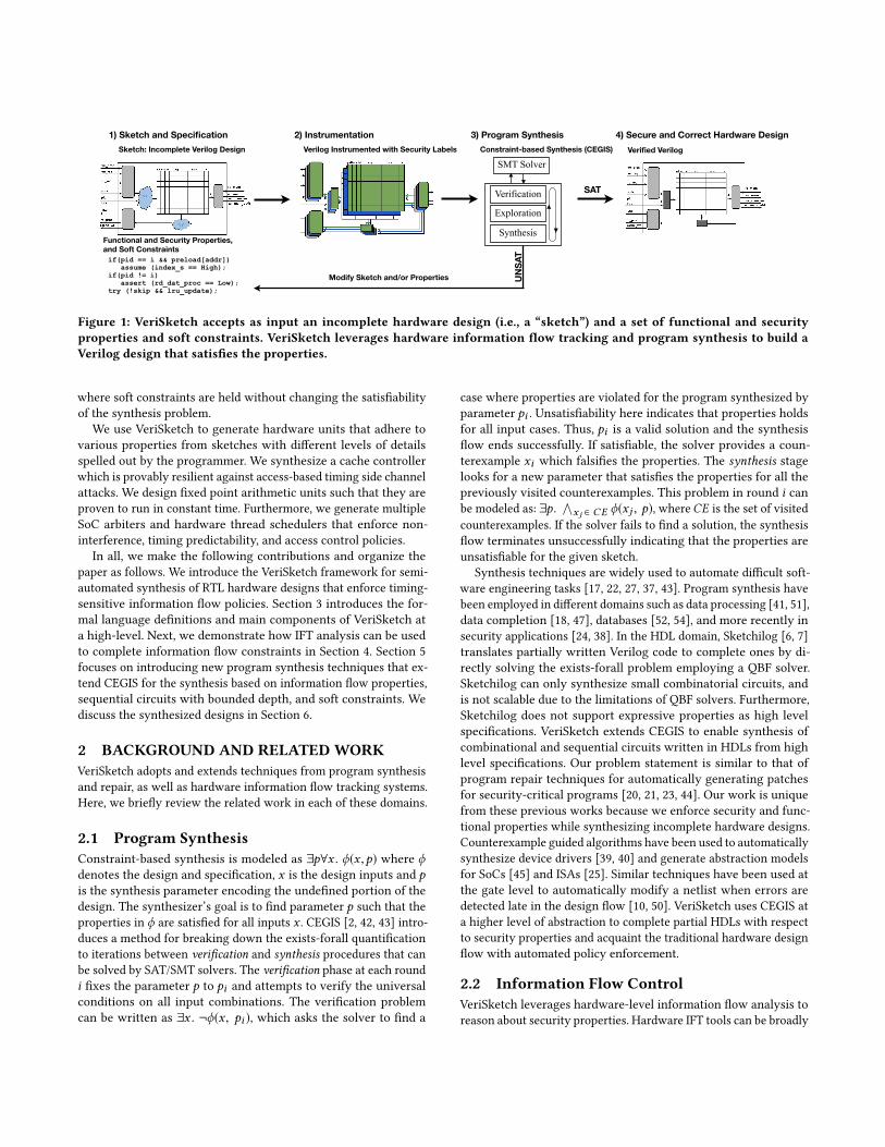
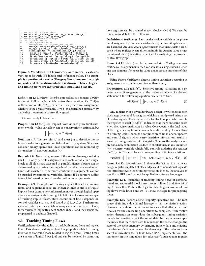
Figure 2: Sketching the control logic for a modified and se-cure version of PLCache. (a) A high-level sketch written inVeriSketch. comb denotes a combinational circuit where theimplementation is totally unspecified. (b) Another sketchfor the same design with more provided details.
Example 3.1 (Sketching a Secure Cache). Fig. 2 shows two exam-ple sketches for designing the locking strategy similar to PLCachebut eliminating the metadata timing side channel (and any othersecurity flaws). We define the structural connections between theelements of the secure cache similar to a “normal cache” and leavethe tricky control and arbitration logic for VeriSketch to decide. Onemajor aspect of the partitioning mitigation technique is specifyingthe logic for the skip signal which we leave as undefined. skip
makes the decision about whether to follow a normal cache accessor perform a direct memory access. We also add sketch constructsto decide when the cache LRU bits are updated. We manually ex-tend the cache blocks to store the lock status of the stored datasimilar to PLCache. The difference between the sketches in Fig. 2 isthe amount of detail provided by the designer and conversely thatwhich is left to be determined by VeriSketch. Fig. 2(a) is a high-levelsketch; it states that the skip signal should be some combinationalfunction of the signals rd_rq, wr_rq, hit and lru_block[m]. Here,lru_block is the cache block selected for eviction according tothe replacement policy and m is the index of the bit which storesthe lock status of the block. The sketch for determining how theLRU bits are updated is a combinational function depending onthe signals rd_rq, wr_rq, lock, stall and waiting. Here, lockis the incoming lock request and waiting shows if the cache isaccessing the memory. The sketch in Fig. 2(b) has more detail; herethe designer provided additional information that the skip signal islow when there is a cache hit and the structure of the logic drivingthe lru_update signal is given. The ?? syntax assumes one bit ifnot specified.
4 INFORMATION FLOW TRACKINGTraditional HDLs like Verilog and VHDL lack a framework for cap-turing security traits. Information flow models enable the analysisof a wide range of hardware security properties such as confiden-tiality, integrity, isolation, and timing side channels. IFT tools definelabels which convey security attributes of design variables (e.g.,whether or not that variable contains sensitive or untrusted infor-mation). IFT models capture how data moves through the system,enabling an analysis of security behaviors of the hardware design.For instance, in order to assess unintended data leakage in a design,secret inputs are initialized with a High label. Next, the design isanalyzed to ensure that public outputs maintain a Low label, whichindicates that no secret data has reached these ports.
4.1 VeriSketch IFT FrameworkVeriSketch tracks information flow by annotating each design vari-able (wire or register) v with two different security labels, vs andvt , where the s-labels track logical flows and t-labels track timingflows. Inference rules for propagating these labels are formalizedin Table 2. VeriSketch defines the propagation rule for each as-signment within the same block by using the same syntax as ofthe original assignment. For instance, label of a register which isupdated in a non-blocking procedural assignments is defined via anon-blocking procedural assignments while label of a wire which isdriven by combinational logic is defined using combinational logicas well. This ensures that variables and their labels are updatedsimultaneously. VeriSketch performs precise label propagation, i.e.,all label updates take into account the exact Boolean values of thedesign at the given time. This is enabled by modeling labels andinference rules with standard Verilog syntax and leveraging EDAtools to reason about the IFT labels and design variables at once.
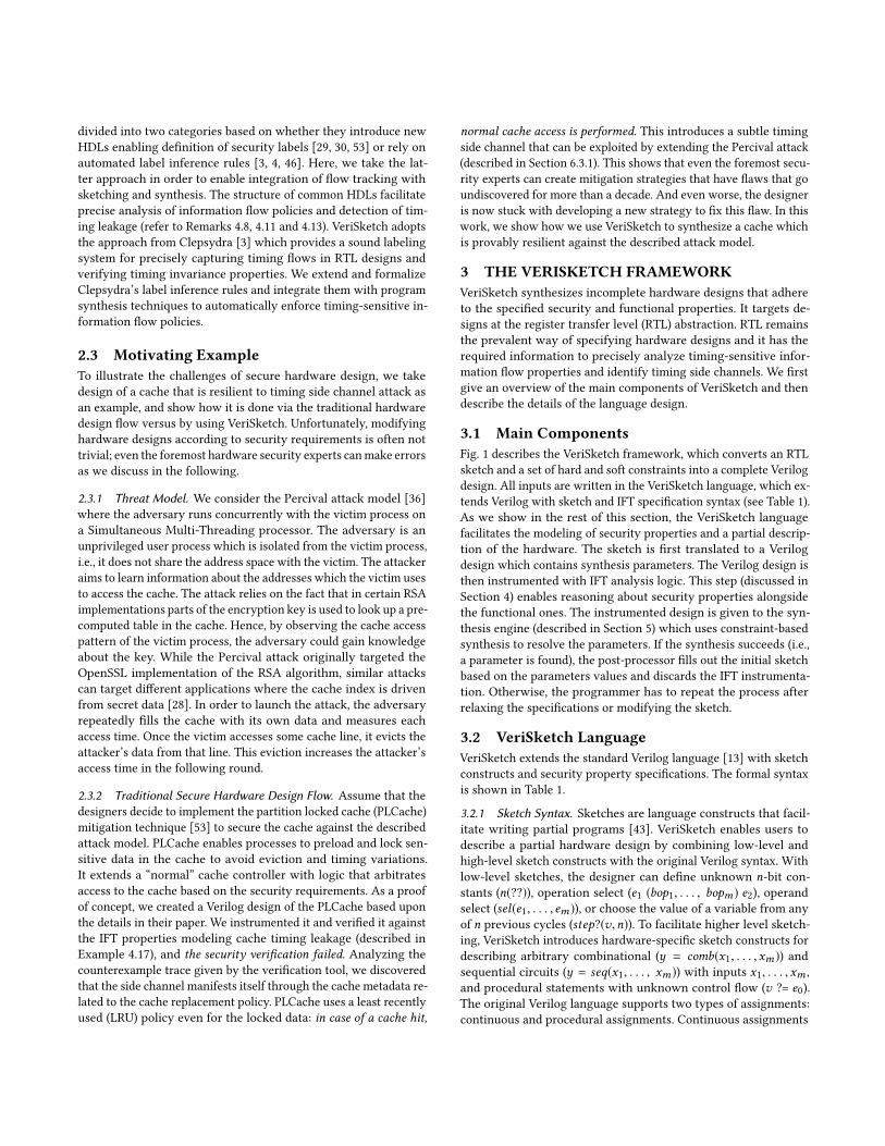
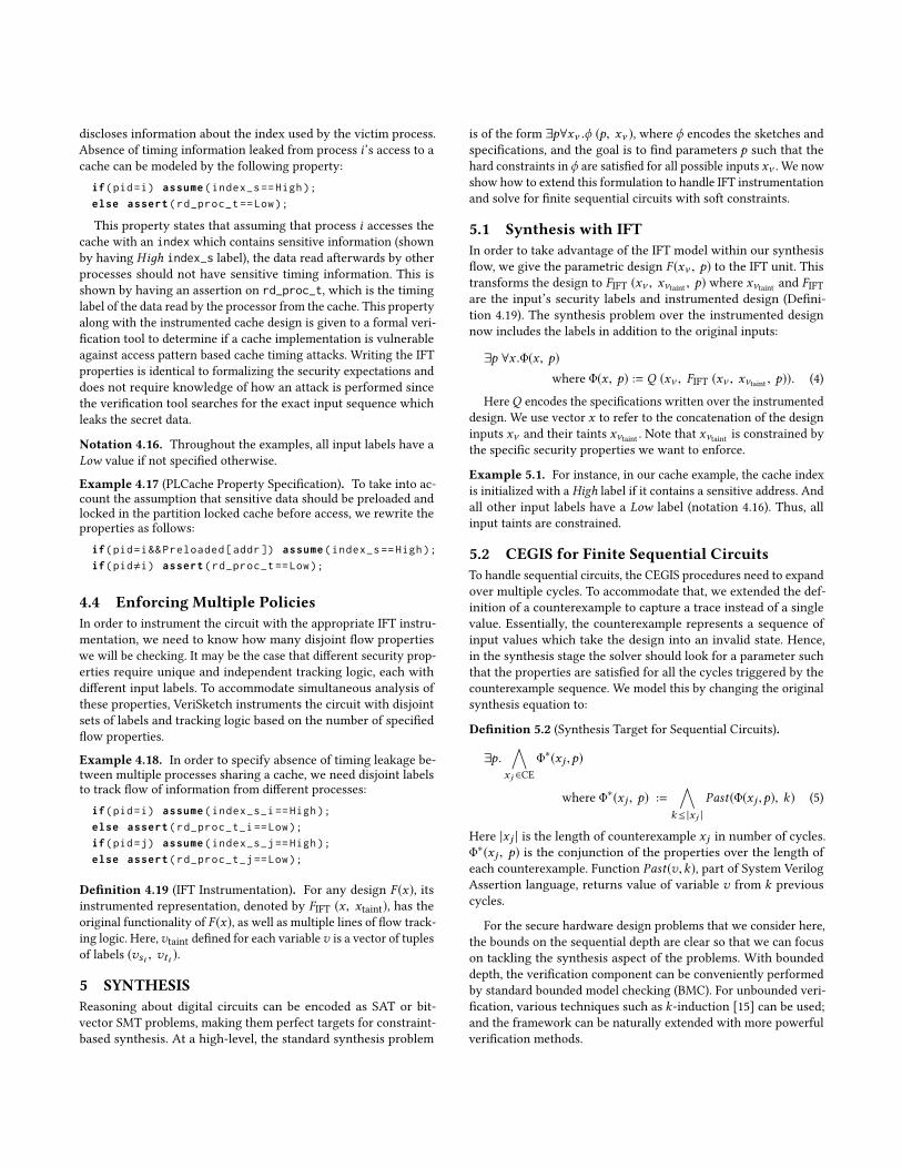
Example 4.1. Fig. 3 shows the IFT instrumentation for a snippetof Verilog code implementing a cache unit. Lines 1 − 3 and 7 − 16show how instrumentation for combinational and sequential blocksare done within the same block following the syntax of the original
Table 2: VeriSketch Label Inference Rules.
Γ ⊢ e :: (s, t)T-uop
Γ ⊢ uop e :: (uopift (e, s), t)
Γ ⊢ e1 :: (s1, t1), e2 :: (s2, t2) T-bopΓ ⊢ e1 bop e2 :: ( bopift (e1, s1, e2, s2), t1 ⊔ t2)
Γ ⊢ e :: (s, t), assign v = eT-assign
Γ ⊢ v :: (s, t)
Γ ⊢ e :: (s, t), v=ηe , ci ∈ Ctrl(v) :: (si , ti )T-blocking
Γ ⊢ v :: (s ⊔ si , t ⊔ ti ⊔ (¬Bal(v) ⊓ si ))
Γ ⊢ e :: (s, t), v ⇐η e , ci ∈ Ctrl(v) :: (si , ti )T-nonblocking
Γ ⊢ v :: (s ⊔ si , t ⊔ ti ⊔ (¬Bal(v) ⊓ si ))
code. Note that all assignments and nonblocking statements areexecuted simultaneously in Verilog. Hence, all variables (e.g., stall)and their labels (e.g., stall_s and stall_t) are updated at the sametime. We will discuss the detail of the right hand-side logic in thefollowing subsections.
Remark 4.2. The blocking (=η ) and nonblocking ( <=η ) assign-ments for statement η differ in that blocking assignments are per-formed sequentially while the nonblocking ones run in parallel.They have the same inference logic according to Table 2, to ensurethat variables and their labels are updated simultaneously.
Remark 4.3. Labels of variables defined via procedural assign-ments are triggered by the same event as the original statement andare defined in the same block. This ensures synchronous updatesto variables and their labels.
In the following, we go over the details of the label inferencerules. Note that since sketch constructs are pre-processed beforethe instrumentation, the inference rules are only defined for theoriginal Verilog syntax.
4.2 Tracking Logical FlowsLogical flows are tracked via label vs defined for each variablev . VeriSketch tracks both explicit and implicit flows (i.e., flow ofinformation via the data path and the control path). Explicit flowsare tracked by instrumenting each operation.
Definition 4.4 (IFT Operator). Let op be a valid binary/unaryoperator in Verilog RTL. IFT operator opift computes the label ofop’s output based on its inputs’ values and labels.
For instance, explicit flows of assignment z = x bop y are trackedvia zs = bopift(x ,xs ,y,ys ). In the simplest case, zs is the join (⊔) ofxs and ys . In a more precise analysis (i.e., lower number of falsepositives), zs also depends on the Boolean values (i.e., x and y) andthe operator’s functionality [4, 26]. IFT operators are pre-definedand stored in VeriSketch IFT library where label tracking precisionlevel is controllable by the user.
Implicit flows for each statement are tracked by upgrading the la-bel of the left hand-side variable according to the labels of variableswhich control the statement’s execution.
1. assign stall = rq && miss;2. assign stall_s = and_ift (rq, rq_s, miss, miss_s);3. assign stall_t = rq_t || miss_t;4. always @ (posedge clk) begin5. if(rd_rq && stall) 6. if(stall_cycles == N)7. cache[index] <= {rd_data_mem,tag,pid};8. cache_s[index] <= {rd_data_mem_s,tag_s,pid_s} |9. rd_rq_s | stall_s | stall_cycles_s | index_s;10. cache_t[index] <= {rd_data_mem_t,tag_t,pid_t} |11. rd_rq_t | stall_t | stall_cycles_t | index_t |12. ((rd_rq_s | stall_s | stall_cycles_s | index_s)13. &&!Bal(cache[index]) && !((!rd_rq_s & Full(rd_rq,14. cache[index]))|(!stall_s & Full(stall, cache[index]))15. |(!stall_cycles_s & Full(stall_cycles, cache[index]))16. |(!index_s & Full(index, cache[index]))));
(a)
Figure 3: VeriSketch IFT framework automatically extendsVerilog code with IFT labels and inference rules. The exam-ple is a portion of a cache. The gray lines here are the origi-nal code and the instrumentation is shown in black. Logicaland timing flows are captured via s-labels and t-labels.
Definition 4.5 (Ctrl(v)). Let η be a procedural assignment.Ctrl(η)is the set of all variables which control the execution of η. Ctrl(v)is the union of all Ctrl(ηi ) where ηi is a procedural assignmentwhere v is the l-value variable. Ctrl(v) is determined statically byanalyzing the program control flow graph.
It immediately follows that:
Proposition 4.6 (c.f. [34]). Implicit flows via each procedural state-ment η with l-value variable v can be conservatively estimated by:⊔
{cis : ci ∈ Ctrl(v)} (1)
Notation 4.7. We use join (⊔) and meet (⊓) to describe the in-ference rules in a generic multi-level security system. Since weconsider binary operations, these operations can be replaced bydisjunction (∨) and conjunction (∧).
Remark 4.8. Note that grammar of the Verilog language and sim-ilar HDLs only permits assignments to each variable in a singleblock as all blocks are executed in parallel. Hence, Ctrl(v) can bedetermined by analyzing the single block in which v is used as lefthand-side variable. Furthermore, continuous assignments cannotbe guarded by conditional variables. Hence, IFT operators sufficeto track information flow through continuous assignments.
Example 4.9. Examples of tracking explicit flows for combina-tional and sequential code are shown in lines 2 and 8 of Fig. 3.Explicit flows capture how information moves through logical oper-ations and assignments from right to left. Line 9 shows an exampleof tracking implicit flows. Here, execution of line 7 depends oncontrol variables rd_req, stall, and stall_cycles. Furthermore,value of index specifies which memory element is accessed. Hence,these variables implicitly affect cache[index] and their labels arepropagated to cache_s[index].
4.3 Tracking Timing FlowsVeriSketch provides the ability to track both timing flows and logicalflows. This allows the designer to define properties related to timinginvariance alongside those related to logical flows. Timing flowsare a subset of logical flows [34] and can be modeled by capturing
how registers can be updated at each clock cycle [3]. We describethis in more detail in the following.
Definition 4.10 (Bal(v)). Letv be the l-value variable in the proce-dural assignment η. Boolean variable Bal(v) declares if updates tovare balanced. An unbalanced update means that there exists a clockcycle where register v can either maintain its current value or getreassigned. Bal(v) is statically decided by analyzing the programcontrol flow graph.
Remark 4.11. Bal(v) can be determined since Verilog grammarconfines all assignments to each variable v to a single block. Hence,one can compute if v keeps its value under certain branches of thatblock.
Using Bal(v) VeriSketch detects timing variation occurring atassignments to variable v and tracks them via vt .
Proposition 4.12 (c.f. [3]). Sensitive timing variations in a se-quential circuit are generated at the l-value variable v of a clockedstatement if the following equation evaluates to true:
¬Bal(v) ⊓⊔{cis : ci ∈ Ctrl(v)} (2)
Any register v in a given hardware design is written to at eachclock edge by a set of data signals which are multiplexed using a setof control signals. The existence of a feedback loop which connectsthe register to itself (¬Bal(v)) indicates that there are some caseswhen the register maintains its value. Consequently, the final valueof the register may become available at different cycles resultingin a timing leak. Hence, the conjunction of unbalanced updatesand control signals which carry sensitive information results insensitive timing variation at the register. To make the analysis moreprecise, a new conjunction is added to check if there is any untainted(¬cis ) control variable which fully controls updating the register(Full(v, ci )). This enables safe downgrading of timing variations:
¬Bal(v) ⊓⊔
cis ⊓ ¬⊔(¬cis ⊓ Full(v, ci )) : ci ∈ Ctrl(v) (3)
Remark 4.13. Proposition 4.12 relies on the fact that in a hardwaredesign registers updated at clock edges and combinational logic donot introduce cycle-level timing variation. Hence, the analysis isspecific to HDLs and cannot be applied to software languages.
Example 4.14. Examples of tracking timing flows in combina-tional and sequential blocks are shown in lines 3 and 10 − 16 ofFig. 3. Lines 12 − 16 show the logic for detecting occurrence of tim-ing flows while lines 3 and 10 − 11 show the logic for propagatingthem.
Example 4.15 (Secure Cache Property Specification). The rootcause of timing side channel leakage is that the victim’s actionchanges the state of the hardware in a way that affects the timeit takes for the succeeding operations to complete. If the victimaction depends on secret data, the subsequent timing variationreveals information about the secret data. In the cache example,the index that the victim uses to read from the cache changes thestate of the cache memory by bringing in new data and evictingthe adversary’s data to the next level memory. If the index containssecret information (as in table-based RSA implementation), theincrement in the time taken for adversary’s subsequent request
discloses information about the index used by the victim process.Absence of timing information leaked from process i’s access to acache can be modeled by the following property:
if(pid=i) assume(index_s ==High);
else assert(rd_proc_t ==Low);
This property states that assuming that process i accesses thecache with an index which contains sensitive information (shownby having Hiдh index_s label), the data read afterwards by otherprocesses should not have sensitive timing information. This isshown by having an assertion on rd_proc_t, which is the timinglabel of the data read by the processor from the cache. This propertyalong with the instrumented cache design is given to a formal veri-fication tool to determine if a cache implementation is vulnerableagainst access pattern based cache timing attacks. Writing the IFTproperties is identical to formalizing the security expectations anddoes not require knowledge of how an attack is performed sincethe verification tool searches for the exact input sequence whichleaks the secret data.
Notation 4.16. Throughout the examples, all input labels have aLow value if not specified otherwise.
Example 4.17 (PLCache Property Specification). To take into ac-count the assumption that sensitive data should be preloaded andlocked in the partition locked cache before access, we rewrite theproperties as follows:
if(pid=i&& Preloaded[addr]) assume(index_s ==High);
if(pid,i) assert(rd_proc_t ==Low);
4.4 Enforcing Multiple PoliciesIn order to instrument the circuit with the appropriate IFT instru-mentation, we need to know how many disjoint flow propertieswe will be checking. It may be the case that different security prop-erties require unique and independent tracking logic, each withdifferent input labels. To accommodate simultaneous analysis ofthese properties, VeriSketch instruments the circuit with disjointsets of labels and tracking logic based on the number of specifiedflow properties.
Example 4.18. In order to specify absence of timing leakage be-tween multiple processes sharing a cache, we need disjoint labelsto track flow of information from different processes:
if(pid=i) assume(index_s_i ==High);
else assert(rd_proc_t_i ==Low);
if(pid=j) assume(index_s_j ==High);
else assert(rd_proc_t_j ==Low);
Definition 4.19 (IFT Instrumentation). For any design F (x), itsinstrumented representation, denoted by FIFT (x , xtaint), has theoriginal functionality of F (x), as well as multiple lines of flow track-ing logic. Here,vtaint defined for each variablev is a vector of tuplesof labels (vsi , vti ).
5 SYNTHESISReasoning about digital circuits can be encoded as SAT or bit-vector SMT problems, making them perfect targets for constraint-based synthesis. At a high-level, the standard synthesis problem
is of the form ∃p∀xν .ϕ (p, xν ), where ϕ encodes the sketches andspecifications, and the goal is to find parameters p such that thehard constraints in ϕ are satisfied for all possible inputs xν . We nowshow how to extend this formulation to handle IFT instrumentationand solve for finite sequential circuits with soft constraints.
5.1 Synthesis with IFTIn order to take advantage of the IFT model within our synthesisflow, we give the parametric design F (xν , p) to the IFT unit. Thistransforms the design to FIFT (xν , xνtaint , p) where xνtaint and FIFTare the input’s security labels and instrumented design (Defini-tion 4.19). The synthesis problem over the instrumented designnow includes the labels in addition to the original inputs:
∃p ∀x .Φ(x , p)where Φ(x , p) := Q (xν , FIFT (xν , xνtaint , p)). (4)
HereQ encodes the specifications written over the instrumenteddesign. We use vector x to refer to the concatenation of the designinputs xν and their taints xνtaint . Note that xνtaint is constrained bythe specific security properties we want to enforce.
Example 5.1. For instance, in our cache example, the cache indexis initialized with a High label if it contains a sensitive address. Andall other input labels have a Low label (notation 4.16). Thus, allinput taints are constrained.
5.2 CEGIS for Finite Sequential CircuitsTo handle sequential circuits, the CEGIS procedures need to expandover multiple cycles. To accommodate that, we extended the def-inition of a counterexample to capture a trace instead of a singlevalue. Essentially, the counterexample represents a sequence ofinput values which take the design into an invalid state. Hence,in the synthesis stage the solver should look for a parameter suchthat the properties are satisfied for all the cycles triggered by thecounterexample sequence. We model this by changing the originalsynthesis equation to:
Definition 5.2 (Synthesis Target for Sequential Circuits).
∃p.∧
x j ∈CEΦ∗(x j ,p)
where Φ∗(x j , p) :=∧
k≤ |x j |
Past(Φ(x j ,p), k) (5)
Here |x j | is the length of counterexample x j in number of cycles.Φ∗(x j , p) is the conjunction of the properties over the length ofeach counterexample. Function Past(v,k), part of System VerilogAssertion language, returns value of variable v from k previouscycles.
For the secure hardware design problems that we consider here,the bounds on the sequential depth are clear so that we can focuson tackling the synthesis aspect of the problems. With boundeddepth, the verification component can be conveniently performedby standard bounded model checking (BMC). For unbounded veri-fication, various techniques such as k-induction [15] can be used;and the framework can be naturally extended with more powerfulverification methods.
5.3 CEGIS for Soft ConstraintsCEGIS could potentially suggest any programwhich does not falsifythe formal properties. Thus, the properties should effectively elimi-nate all undesirable programs. This makes property specification amajor challenge. For example, consider the cache example whereIFT properties similar to Example 4.17 are in place to eliminateside-channel leakage and synthesize the sketch from Fig. 2(a). Atrivial implementation that results from this sketch and satisfiesthe IFT properties is a design that skips all cache accesses. Whilethis satisfies the security properties, it is not what the designer in-tended to get. However, it is not clear how to formalize the propertybeing violated in this case. The designer can potentially get aroundthis issue by providing input/output (I/O) pairs which should begenerated by the synthesized design, extending the formal prop-erties, or shrinking the sketch such that undesirable programs areunreachable. However, all these approaches require non-trivial ef-fort from the designer. Instead, we take an automated approach toheuristically guide the search algorithm to avoid recommendingundesirable designs. We introduce soft constraints for specifyingproperties which may not hold for all cases but it is desirable ifthey do. Soft constraints are particularly beneficial for modelingperformance attributes.
Definition 5.3 (Soft Constraint). Soft constraints are logical for-mulas that model properties which are preferably true. We showsoft constraints for the design being synthesized by T (x , p).
Example 5.4. A soft constraint for synthesizing the secure cachecan be defined by indicating that that having a low value for theskip signal and a high value for the lru_update signal (from Fig. 2)are desirable.While this constraint cannot be strictly enforced if onewants to eliminate timing side channel, we use it to guide CEGIS tofind a design which does not skip cache writes and updates the LRUif possible. Using the try keyword to model the soft constraints, werewrite the properties for synthesizing a secure cache as follows:
if(pid=i&& Preloaded[addr]) assume(index_s ==High);
if(pid,i) assert(rd_proc_t ==Low);
try(!skip && lru_update );
In order to enforce soft constraints via synthesis, we extend theCEGIS algorithm to further explore the input space by searchingfor positive examples.
Definition 5.5 (Positive Example). Positive example pe for thedesign synthesized with p = pi is any input trace which satisfiesthe specification Φ∗(x , pi ).
Positive examples represent cases where the design is workingcorrectly according to the hard constraints. Positive examples aregathered after each verification round by searching the input spacesurrounding the newly found counterexample.
Definition 5.6 (Exploration). The exploration round computesthe set of positive examples PE by searching the design space sur-rounding each counterexample x . Exploration can be modeled bythe following SAT problem for xm ∈ x :
∃a. Φ∗(a, pi ) ∧∧
x j ∈x∧j,m
(aj = x j ) (6)
While the original CEGIS algorithm tries to fix the design byenforcing hard constraints on the counterexamples, we direct it tofurther enforce soft constraints on the collected positive examples.This is done by modifying the synthesis round to find a design suchthat soft constraints are held for the maximum possible number ofcollected positive examples while hard constraints are held for allvisited counterexamples. This new synthesis problem is defined by:
Definition 5.7 (Synthesis Target for Soft Constraints T ).
∃p.∧
x j ∈CEΦ∗(x j , p) ∧
∑xi ∈PE
T ∗(xi , p) = n
where T ∗(xi , p) :=∧
k≤ |xi |
Past(T (xi , p), k) (7)
The synthesis round iteratively solves Eq.7 and decreases n from|PE | to zero if unsatisfiable.
Theorem 5.8. If satisfiable, CEGIS with soft constraints finds theprogram which enforces soft constraints on the maximum numberof collected positive examples.
Proof Outline. Each synthesis round solves Eq.7 by setting n :=|PE | initially and decrease n if unsatisfiable. Hence, if satisfiable,parameter p represents the design where soft constraints are heldfor maximum n ≤ |PE |. □
ALGORITHM 1: Given sketch F (x), hard constraints C(x),and soft constraints C ′(x), VeriSketch generates Fsyn(x).Input :F (x),C (x), C ′ (x) : VeriSketchOutput :Fsyn (x) s.t. ∀x . C(x) : Verilog
1 F (x ,p) ← pre-processing (F (x))2 FIFT (x , xtaint, p) ← instrumentation (F (x ,p),C(x))3 P ← CEGIS (FIFT (x , xtaint, p), C(x), C ′(x))4 if P , unsat then5 Fsyn(x) ← post-processing (F (x ,p), P)6 return Fsyn7 else return unsat
Soft constraints are ignored in the verification round since theydo not necessarily hold for all input traces. This means that theequisatisfiability of the synthesis problem does not change as softconstraints are added. Hence, one can add soft constraints withoutworrying about making the problem unsatisfiable.
Theorem 5.9. Soft constraints do not impact satisfiability of thesynthesis problem.
Proof Outline. The synthesis parameter, the verification equation,and hence the domain of valid programs remain the same by addingsoft constraints. Furthermore, the synthesis equation in each roundreduces to the original synthesis equation (i.e., Eq.5) in the worstcase. Thus, the satisfiability does not change. □
Synthesis by soft constraints combines techniques from property-based and example-based synthesis by automatically searching forexamples which should be generated by the synthesized design.
ALGORITHM 2: Counterexample guided inductive synthe-sis (CEGIS) for synthesizing sequential circuits with soft con-straintsInput :Φ (x , p), T (x , p)Output :pi s.t. ∀x . Φ(x ,pi )
1 Initial Stage:2 pi ← random assignment3 CE ← ∅
4 PE ← ∅
5 while 1 do6 Verification Phase:7 ce ← SAT (∃x . ¬Φ(x ,pi ))8 if ce = unsat then return pi9 else
10 CE ← CE ∪ ce
11 Exploration Phase:12 pem ← SAT (∃a.Φ∗(a, pi ) ∧ ∧
ce j ∈ce ∧ j,maj = ce j )
13 Φ∗(a, p) :=∧
k≤ |a |Past(Φ(a, p), k)
14 if pem , unsat then PE ← PE ∪ pem ;15 Synthesis Phase:16 for (l = |PE |; l ≥ 0; i = i − 1) do17 solution ← SAT ∃p. ∧
x j ∈CEΦ∗(x j ,p) ∧ (sumpe = l)
18 sumpe :=∑
x ′j ∈PET ∗(x
′
j ,p)
19 T ∗(x′
j ,p) :=∧
k≤ |x ′j |Past(T (x
′
j , p), k)
20 Φ∗(x j , p) :=∧
k≤ |x j |Past(Φ(x j , p), k)
21 if solution,unsat then pi ← solution; break22 else if l=0 then return unsat
23 end24 end
Alternatively, one can manually specify the positive examples; how-ever, defining traces of examples for sequential circuits may be chal-lenging itself. The overall VeriSketch flow and CEGIS algorithm forsynthesizing sequential circuits with soft constraints are shown inAlgorithm 1 and 2, respectively.
6 EXPERIMENTSWe now demonstrate four examples of security-critical hardwaredesigns that are successfully synthesized by VeriSketch.• Constant Time Arithmetic Units We implement fixedpoint arithmetic units which run in constant time. We useIFT specification to model constant time behaviour and non-synthesizable1 portion of the Verilog language to modelfunctional properties.• Leakage-free caches:We add sketch constructs (followingthe partition lock methodology [48]) to traditional cache
1Synthesizable in this case refers to the portion of the language that can be mapped toa gate-level netlist. Complex Verilog operators can only be used in simulation.
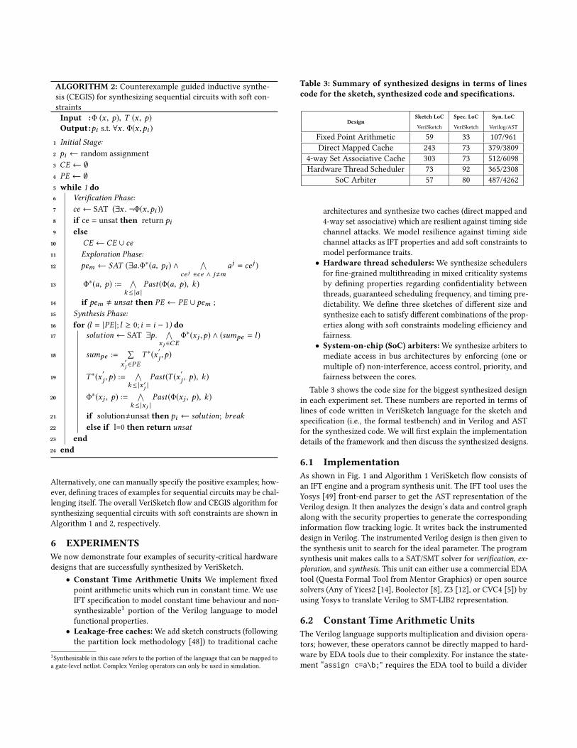
Table 3: Summary of synthesized designs in terms of linescode for the sketch, synthesized code and specifications.
DesignSketch LoC Spec. LoC Syn. LoC
VeriSketch VeriSketch Verilog/AST
Fixed Point Arithmetic 59 33 107/961Direct Mapped Cache 243 73 379/3809
4-way Set Associative Cache 303 73 512/6098Hardware Thread Scheduler 73 92 365/2308
SoC Arbiter 57 80 487/4262
architectures and synthesize two caches (direct mapped and4-way set associative) which are resilient against timing sidechannel attacks. We model resilience against timing sidechannel attacks as IFT properties and add soft constraints tomodel performance traits.• Hardware thread schedulers: We synthesize schedulersfor fine-grained multithreading in mixed criticality systemsby defining properties regarding confidentiality betweenthreads, guaranteed scheduling frequency, and timing pre-dictability. We define three sketches of different size andsynthesize each to satisfy different combinations of the prop-erties along with soft constraints modeling efficiency andfairness.• System-on-chip (SoC) arbiters:We synthesize arbiters tomediate access in bus architectures by enforcing (one ormultiple of) non-interference, access control, priority, andfairness between the cores.
Table 3 shows the code size for the biggest synthesized designin each experiment set. These numbers are reported in terms oflines of code written in VeriSketch language for the sketch andspecification (i.e., the formal testbench) and in Verilog and ASTfor the synthesized code. We will first explain the implementationdetails of the framework and then discuss the synthesized designs.
6.1 ImplementationAs shown in Fig. 1 and Algorithm 1 VeriSketch flow consists ofan IFT engine and a program synthesis unit. The IFT tool uses theYosys [49] front-end parser to get the AST representation of theVerilog design. It then analyzes the design’s data and control graphalong with the security properties to generate the correspondinginformation flow tracking logic. It writes back the instrumenteddesign in Verilog. The instrumented Verilog design is then given tothe synthesis unit to search for the ideal parameter. The programsynthesis unit makes calls to a SAT/SMT solver for verification, ex-ploration, and synthesis. This unit can either use a commercial EDAtool (Questa Formal Tool from Mentor Graphics) or open sourcesolvers (Any of Yices2 [14], Boolector [8], Z3 [12], or CVC4 [5]) byusing Yosys to translate Verilog to SMT-LIB2 representation.
6.2 Constant Time Arithmetic UnitsThe Verilog language supports multiplication and division opera-tors; however, these operators cannot be directly mapped to hard-ware by EDA tools due to their complexity. For instance the state-ment “assign c=a\b;" requires the EDA tool to build a divider
module div (clk, start, dividend, divisor, quotient, done, overflow); assign flag = reg_a (>=,>,<,=>) reg_b; always @(posedge clk) begin if( done && start) //initialize … reg_q[reg_count] ?= ??; reg_b ?= reg_b(>>, <<, <<<, >>>) ??; reg_a ?= reg_a - reg_b; quotient ?= reg_q; ctrl_vars = [start, done, count_done, flag]; //counter, overflow and sign logic …
assert (dividend, divisor -/->t quotient); assert (done && divisor!=0 |->(|quotient-((dividend << Q)/divisor)|<=1));
endmodule
module div (clk, start, dividend, divisor, quotient, done, overflow); assign flag = reg_a >= reg_b; always @(posedge clk) begin if(done && start) //initialize … if(!reg_done && !count_done && (reg_a >= reg_b)) reg_q [reg_count] <= 1; if(!reg_done) reg_b <= reg_b << 1; if(!reg_done && (reg_a >= reg_b)) reg_a <= reg_a - reg_b; if (!start & !done & count_done) quotient <= reg_q; //counter, overflow and sign logic …
endmodule (a) (b)
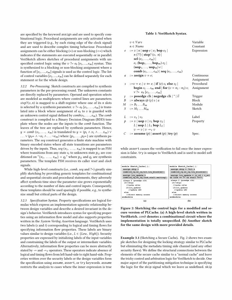
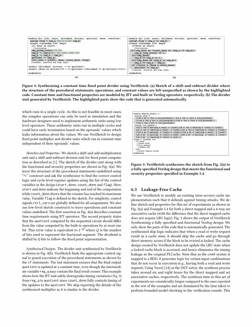
Figure 4: Synthesizing a constant time fixed point divider using VeriSketch. (a) Sketch of a shift-and-subtract divider wherethe structure of the procedural statements, operations, and constant values are left unspecified as shown by the highlightedcode. Constant time and functional properties are modeled by IFT and built-in Verilog operators, respectively. (b) The dividerunit generated by VeriSketch. The highlighted parts show the code that is generated automatically.
which runs in a single cycle. As this is not feasible in most cases,the complex operations can only be used in simulation and thehardware designers need to implement arithmetic units using lowlevel operators. These arithmetic units run in multiple cycles andcould have early termination based on the operands’ values whichleaks information about the values. We use VeriSketch to designfixed point multiplier and divider units which run in constant timeindependent of their operands’ values.
Sketches and Properties. We sketch a shift-and-add multiplicationunit and a shift-and-subtract division unit for fixed point computa-tion as described in [1]. The sketch of the divider unit along withthe functional and security properties are shown in Fig. 4(a). Weleave the structure of the procedural statements undefined using“?=” construct and ask the synthesizer to find the correct controllogic and cycle-level register updates using the list of the controlvariables in the design (start,done,count_done and flag). Here,start and done indicate the beginning and end of the computationwhile count_done shows that the counter has reached its maximumvalue. Variable flag is defined in the sketch. For simplicity, controlsignals ctrl_vars are globally defined for all assignments. We alsouse low-level sketch constructs to leave operations and constantvalues undefined. The first assertion in Fig. 4(a) describes constanttime requirements using IFT operators. The second property statesthat the quotient computed by the sequential circuit should differfrom the value computed by the built-in operations by at most onebit. This error value is equivalent to 2−Q where Q is the numberof bits used to represent the fractional segment. The dividend isshifted by Q bits to follow the fixed point representation.
Synthesized Designs. The divider unit synthesized by VeriSketchis shown in Fig. 4(b). VeriSketch finds the appropriate control sig-nal to guard execution of the procedural statements as shown bythe if statements. The last statement ensures that the final outputquotient is updated at a constant time, even though the intermedi-ate variable reg_qmay contain the final result sooner. This exampleshows how the IFT unit safely downgrades timing variations ( Eq. 3)from reg_q to quotient since count_done fully controls timing ofthe updates to the quotient. We skip reporting the details of thesynthesized multiplier as it is similar to the divider.
module Sketch_Cache(…); assign skip = (!rd & wr & !hit & lru_block[m])| (rd & !wr & !hit & lru_block[m]) |(!rd & !wr & hit & lru_block[m])|(!rd & !wr & !hit & lru_block[m])| (!rd & !wr & hit & !lru_block[m]); assign lru_update = (rd & !wr & waiting & stall & !lock)|(rd & !wr & waiting & !stall & !lock)| (rd & !wr & !waiting & stall & !lock)|(rd & !wr & !waiting & !stall & !lock)| (!rd & wr & waiting & !stall & !lock)|(!rd & wr & !waiting & stall & !lock)| (rd & wr & waiting & !stall & lock) |(rd & wr & waiting & !stall & !lock)| (rd & wr & !waiting & !stall & lock ); always @ (posedge clk) if(!skip) //cache rd/wr if(lru_update) //update LRU else //direct memory accessendmodule
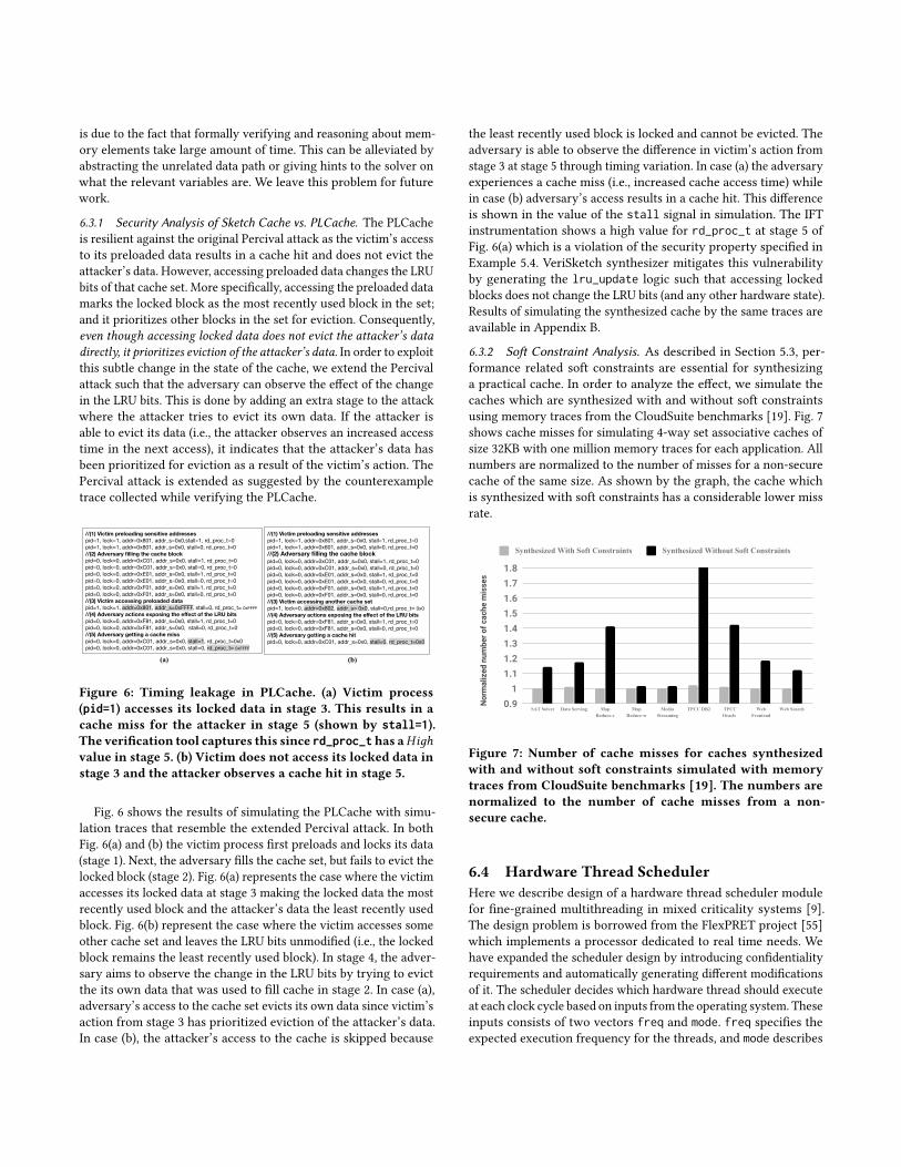
Figure 5: VeriSketch synthesizes the sketch from Fig. 2(a) toa fully specifiedVerilog design thatmeets the functional andsecurity properties specified in Example 5.4.
6.3 Leakage-Free CacheWe use VeriSketch to modify an existing (non-secure) cache im-plementation such that it defends against timing attacks. We de-fine sketch and properties for this set of experiments as shown inFig. 2(a) and Example 5.4 for both a direct mapped and a 4-way setassociative cache (with the difference that the direct mapped cachedoes not require LRU logic). Fig. 5 shows the output of VeriSketchSynthesizing a fully specified and functional Verilog design. Weonly show the parts of the code that is automatically generated. Thesynthesized skip logic indicates that when a read or write requestresult in a cache miss, it should skip the cache and go throughdirect memory access if the block to be evicted is locked. The cachedesign created by VeriSketch does not update the LRU state whena locked cache block is accessed, and hence eliminates the timingleakage in the original PLCache. Note that as the comb syntax ismapped to a BDD, it generates logic for certain input combinationsthat do not occur in execution (e.g., having both a read and writerequest). Using Yices2 [14] as the SMT solver, the synthesis processtakes around six and eight hours for the direct mapped and setassociative caches, respectively. The synthesis time in this set ofexperiments are considerably longer compared to the ones reportedin the rest of the examples and are dominated by the time taken toperform bounded model checking in the verification rounds. This
is due to the fact that formally verifying and reasoning about mem-ory elements take large amount of time. This can be alleviated byabstracting the unrelated data path or giving hints to the solver onwhat the relevant variables are. We leave this problem for futurework.
6.3.1 Security Analysis of Sketch Cache vs. PLCache. The PLCacheis resilient against the original Percival attack as the victim’s accessto its preloaded data results in a cache hit and does not evict theattacker’s data. However, accessing preloaded data changes the LRUbits of that cache set. More specifically, accessing the preloaded datamarks the locked block as the most recently used block in the set;and it prioritizes other blocks in the set for eviction. Consequently,even though accessing locked data does not evict the attacker’s datadirectly, it prioritizes eviction of the attacker’s data. In order to exploitthis subtle change in the state of the cache, we extend the Percivalattack such that the adversary can observe the effect of the changein the LRU bits. This is done by adding an extra stage to the attackwhere the attacker tries to evict its own data. If the attacker isable to evict its data (i.e., the attacker observes an increased accesstime in the next access), it indicates that the attacker’s data hasbeen prioritized for eviction as a result of the victim’s action. ThePercival attack is extended as suggested by the counterexampletrace collected while verifying the PLCache.
//(1) Victim preloading sensitive addresses pid=1, lock=1, addr=0x801, addr_s=0x0,stall=1, rd_proc_t=0pid=1, lock=1, addr=0x801, addr_s=0x0, stall=0, rd_proc_t=0//(2) Adversary filling the cache block pid=0, lock=0, addr=0xC01, addr_s=0x0, stall=1, rd_proc_t=0pid=0, lock=0, addr=0xC01, addr_s=0x0, stall=0, rd_proc_t=0pid=0, lock=0, addr=0xE01, addr_s=0x0, stall=1, rd_proc_t=0pid=0, lock=0, addr=0xE01, addr_s=0x0, stall=0, rd_proc_t=0pid=0, lock=0, addr=0xF01, addr_s=0x0, stall=1, rd_proc_t=0pid=0, lock=0, addr=0xF01, addr_s=0x0, stall=0, rd_proc_t=0//(3) Victim accessing preloaded data pid=1, lock=1, addr=0x801, addr_s=0xFFFF, stall=0, rd_proc_t= 0xFFFF//(4) Adversary actions exposing the effect of the LRU bits pid=0, lock=0, addr=0xF81, addr_s=0x0, stall=1, rd_proc_t=0pid=0, lock=0, addr=0xF81, addr_s=0x0, stall=0, rd_proc_t=0//(5) Adversary getting a cache miss pid=0, lock=0, addr=0xC01, addr_s=0x0, stall=1, rd_proc_t=0x0pid=0, lock=0, addr=0xC01, addr_s=0x0, stall=0, rd_proc_t= 0xFFFF
//(1) Victim preloading sensitive addresses pid=1, lock=1, addr=0x801, addr_s=0x0, stall=1, rd_proc_t=0pid=1, lock=1, addr=0x801, addr_s=0x0, stall=0, rd_proc_t=0//(2) Adversary filling the cache block pid=0, lock=0, addr=0xC01, addr_s=0x0, stall=1, rd_proc_t=0pid=0, lock=0, addr=0xC01, addr_s=0x0, stall=0, rd_proc_t=0pid=0, lock=0, addr=0xE01, addr_s=0x0, stall=1, rd_proc_t=0pid=0, lock=0, addr=0xE01, addr_s=0x0, stall=0, rd_proc_t=0pid=0, lock=0, addr=0xF01, addr_s=0x0, stall=1, rd_proc_t=0pid=0, lock=0, addr=0xF01, addr_s=0x0, stall=0, rd_proc_t=0//(3) Victim accessing another cache set pid=1, lock=0, addr=0x802, addr_s= 0x0, stall=0,rd_proc_t= 0x0//(4) Adversary actions exposing the effect of the LRU bits pid=0, lock=0, addr=0xF81, addr_s=0x0, stall=1, rd_proc_t=0pid=0, lock=0, addr=0xF81, addr_s=0x0, stall=0, rd_proc_t=0//(5) Adversary getting a cache hit pid=0, lock=0, addr=0xC01, addr_s=0x0, stall=0, rd_proc_t=0x0
(a) (b)
Figure 6: Timing leakage in PLCache. (a) Victim process(pid=1) accesses its locked data in stage 3. This results in acache miss for the attacker in stage 5 (shown by stall=1).The verification tool captures this since rd_proc_thas aHiдhvalue in stage 5. (b) Victim does not access its locked data instage 3 and the attacker observes a cache hit in stage 5.
Fig. 6 shows the results of simulating the PLCache with simu-lation traces that resemble the extended Percival attack. In bothFig. 6(a) and (b) the victim process first preloads and locks its data(stage 1). Next, the adversary fills the cache set, but fails to evict thelocked block (stage 2). Fig. 6(a) represents the case where the victimaccesses its locked data at stage 3 making the locked data the mostrecently used block and the attacker’s data the least recently usedblock. Fig. 6(b) represent the case where the victim accesses someother cache set and leaves the LRU bits unmodified (i.e., the lockedblock remains the least recently used block). In stage 4, the adver-sary aims to observe the change in the LRU bits by trying to evictthe its own data that was used to fill cache in stage 2. In case (a),adversary’s access to the cache set evicts its own data since victim’saction from stage 3 has prioritized eviction of the attacker’s data.In case (b), the attacker’s access to the cache is skipped because
the least recently used block is locked and cannot be evicted. Theadversary is able to observe the difference in victim’s action fromstage 3 at stage 5 through timing variation. In case (a) the adversaryexperiences a cache miss (i.e., increased cache access time) whilein case (b) adversary’s access results in a cache hit. This differenceis shown in the value of the stall signal in simulation. The IFTinstrumentation shows a high value for rd_proc_t at stage 5 ofFig. 6(a) which is a violation of the security property specified inExample 5.4. VeriSketch synthesizer mitigates this vulnerabilityby generating the lru_update logic such that accessing lockedblocks does not change the LRU bits (and any other hardware state).Results of simulating the synthesized cache by the same traces areavailable in Appendix B.
6.3.2 Soft Constraint Analysis. As described in Section 5.3, per-formance related soft constraints are essential for synthesizinga practical cache. In order to analyze the effect, we simulate thecaches which are synthesized with and without soft constraintsusing memory traces from the CloudSuite benchmarks [19]. Fig. 7shows cache misses for simulating 4-way set associative caches ofsize 32KB with one million memory traces for each application. Allnumbers are normalized to the number of misses for a non-securecache of the same size. As shown by the graph, the cache whichis synthesized with soft constraints has a considerable lower missrate.
Nor
mal
ized
num
ber o
f cac
he m
isse
s
0.91
1.11.21.31.41.51.61.71.8
SAT Solver Data Serving Map Reduce-c
Map Reduce-w
Media Streaming
TPCC DB2 TPCC Oracle
Web Frontend
Web Search
Synthesized With Soft Constraints Synthesized Without Soft Constraints
Figure 7: Number of cache misses for caches synthesizedwith and without soft constraints simulated with memorytraces from CloudSuite benchmarks [19]. The numbers arenormalized to the number of cache misses from a non-secure cache.
6.4 Hardware Thread SchedulerHere we describe design of a hardware thread scheduler modulefor fine-grained multithreading in mixed criticality systems [9].The design problem is borrowed from the FlexPRET project [55]which implements a processor dedicated to real time needs. Wehave expanded the scheduler design by introducing confidentialityrequirements and automatically generating different modificationsof it. The scheduler decides which hardware thread should executeat each clock cycle based on inputs from the operating system. Theseinputs consists of two vectors freq and mode. freq specifies theexpected execution frequency for the threads, and mode describes
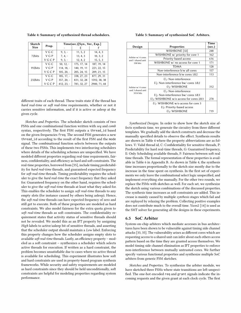
Table 4: Summary of synthesized thread schedulers.
SketchSize Prop. Time(sec.)[Syn., Ver., Exp.]
- E F
72bitsV G C 9, 3, - 11, 5, 2 14, 4, 3V G P 7, 4, - 13, 4, 3 10, 3, 2V G C P 9, 3, - 12, 4, 2 15, 5, 3
192bitsV G C 50, 12, - 175, 17, 14 187, 19, 14V G P 114, 18, - 140, 19, 11 221, 22, 15V G C P 105, 20, - 205, 24, 15 209, 21, 15
232bitsV G C 185, 17, - 338, 27, 23 877, 29, 31V G P 357, 20, - 831, 32, 28 1592, 38, 38V G C P 412, 23, - 781, 32, 27 2900, 71, 44
different traits of each thread. These traits state if the thread hashard real-time or soft real-time requirements, whether or not itcarries sensitive information, and if it is active or asleep at thegiven cycle.
Sketches and Properties. The scheduler sketch consists of twoFSMs and one combinational function written with seq and combsyntax, respectively. The first FSM outputs a thread_id basedon the given frequencies freq. The second FSM generates a newthread_id according to the result of the first FSM and the modesignal. The combinational function selects between the outputsof these two FSMs. This implements two interleaving schedulerswhere details of the scheduling schemes are unspecified. We havemodeled different properties regarding real-time requirements, fair-ness, confidentiality, and efficiency as hard and soft constraints. Thereal-time properties, borrowed from [55], include timing predictabil-ity for hard real-time threads, and guaranteed expected frequencyfor soft real-time threads. Timing predictability requires the sched-uler to give the hard real-time the exact frequency that they askedfor. Guaranteed frequency on the other hand, requires the sched-uler to give the soft real-time threads at least what they asked for.This enables the scheduler to assign soft real-time threads to anyempty slots (for instance caused by others being asleep). Hence,the soft real-time threads can have expected frequency of zero andstill get to execute. Both of these properties are modeled as hardconstraints. We also model fairness for the extra quota given tosoft real-time threads as soft constraints. The confidentiality re-quirement states that activity status of sensitive threads shouldnot be revealed. We model this as an IFT property by assigningHigh labels to active/asleep bit of sensitive threads, and assertingthat the scheduler output should maintain a Low label. Enforcingthis property changes how the scheduler assigns empty slots toavailable soft real-time threads. Lastly, an efficiency property – mod-eled as a soft constraint – synthesizes a scheduler which selectsactive threads for execution. If written as a hard constraint, theproblem becomes unsatisfiable due to cases where no active threadis available for scheduling. This experiment illustrates how softand hard constraints are used in property-based program synthesisframeworks. While security and safety requirements are modeledas hard constraints since they should be held unconditionally, softconstraints are helpful for modeling properties regarding systemperformance.
Table 5: Summary of synthesized SoC Arbiters.
Design PropertiesTime(sec.)
Arbiter w/ 4 coresand 1 shared unit
338 bits
WISHBONE [32] 248WISHBONE w/ priority for core 1 162
Priority-based access 616WISHBONE w/ no access for core 1 171
TDMA 128Non-interference b/w all cores 157Non-interference b/w cores 1&2 113
Arbiter w/ 4 coresand 3 shared unit
1014 bits
U1: Non-interferenceU2: Non-interference bw/ cores 1&2
U3: WISHBONE 312U1: Non-interference
U2: Non-interference bw/ cores 1&3U3: WISHBONE w/o access for cores 2&3 278U1: WISHBONE w/o access for core 3
U2: Priority-based accessU3: WISHBONE 719
Synthesized Designs. In order to show how the sketch size af-fects synthesis time, we generate the circuitry from three differenttemplates. We gradually add the sketch constructs and decrease themanually specified details to observe the effect. Synthesis resultsare shown in Table 4 where the property abbreviations are as fol-lows. V: Valid thread id, C: Confidentiality for sensitive threads, P:Predictability for hard real-time threads, G: Guaranteed frequency,E: Only Scheduling available threads, F: Fairness between soft realtime threads. The formal representation of these properties is avail-able in Table 6 in Appendix B. As shown in Table 4, the synthesistime increases proportionally to the sketch size mostly due to theincrease in the time spent on synthesis. In the first set of experi-ments we only leave the combinational select logic unspecified, andimplement everything else manually. For the other two rounds, wereplace the FSMs with sketches as well. For each set, we synthesizethe sketch using various combinations of the discussed properties.The synthesis time increases as soft constraints are added. This in-crease is mainly caused by multiple synthesis stages which fail andare replayed by relaxing the problem. Collecting positive examplesdoes not contribute much to the overall time. Yices2 [14] is used asthe SMT solver for generating all the designs in these experiments.
6.5 SoC ArbiterSystem-on-chip arbiters which mediate accesses in bus architec-tures have been shown to be vulnerable against timing side channelattacks [33, 35]. The vulnerability arises as different cores which arerequesting access to a shared unit can infer about each others accesspattern based on the time they are granted access themselves. Wemodel timing side channel elimination as IFT properties to enforcenon-interference between mutually untrusted cores. We furtherspecify various functional properties and synthesize multiple SoCarbiters from generic FSM sketches.
Sketches and Properties. To synthesize the arbiter module, wehave sketched three FSMs where state transitions are left unspeci-fied. The one-hot encoded req and grant signals indicate the in-coming requests and the given grant at each clock cycle. The first

two FSMs are defined using seq syntax with different sets of inputs.The first one takes req and grant as inputs, and the second onemodels a smaller FSM where state transitions are independent ofthe incoming requests. While the second FSM models designs thatcan be generated by the first one, it can more quickly synthesize ar-biters where the scheduling is independent of the input (e.g., TDMApolicy). The third sketch models an FSM which groups differentcores in disjoint sets. Finally, we sketch a combinational logic whichselects one of the FSMs. We define two sets of sketches modelingan arbiter module which mediates between four cores sending re-quests to one and three shared units. We define properties regardingaccess control, non-interference, and priority-based scheduling tosynthesize different arbiters. The formal representation of theseproperties is available in Table 7 in Appendix B.
Synthesized Designs. Table 5 shows the result of synthesizingdifferent arbiters by combining different sets of properties. Notethat while the sketch includes multiple FSMs, only one of them ischosen and synthesized by CEGIS. Using this strategy, the sketchcan be automatically selected from a pool of available sketcheseliminating the need to explicitly determine a single template forsynthesis. The first four designs from Table 5 are synthesized bythe first most generic template. The next two designs are gener-ated from our second template. Lastly, adding non-interferenceproperties between two cores results in using the third templatewhere different cores are appropriately placed in separate groups.As we can see from the results, adding IFT properties speeds up thesynthesis procedure because these properties constrain the high-level structure of the design. In the next round of experiments, wereplicated the templates to synthesize an arbiter which mediatesaccesses to three shared units with distinct policies.Ui in the tablerefers to shared uint number i . The last column of Table 5 showsthe time taken for synthesis using Questa Formal Tool.
7 CONCLUSIONThiswork presents a semi-automated and security-orientedmethod-ology for designing hardware with formal proof of security. Theproposed design framework consists of language support for sketch-ing digital circuitry, and a set of techniques for translating partiallywrittenHDL codes into complete designs that provably complywiththe designers’ functional and security specifications. The proposedflow speeds up and simplifies the lengthy process of hardware de-sign and verification, and acquaints the traditional design flow withautomated enforcement of security properties. We have shown howcombining program synthesis techniques with the model of infor-mation flow enables generating hardware units which are correctand secure by construction.
ACKNOWLEDGMENTSThis material is based upon work supported by the National ScienceFoundation under grant no. CNS-1527631 and CNS-1563767.
REFERENCES[1] [n. d.]. The reference community for Free and Open Source gateware IP cores.
https://opencores.org/project,verilog_fixed_point_math_library.[2] Rajeev Alur, Rastislav Bodik, Garvit Juniwal, Milo MK Martin, Mukund
Raghothaman, Sanjit A Seshia, Rishabh Singh, Armando Solar-Lezama, Emina
Torlak, and Abhishek Udupa. 2013. Syntax-guided synthesis. In Formal Methodsin Computer-Aided Design (FMCAD), 2013. IEEE, 1–8.
[3] Armaiti Ardeshiricham, Wei Hu, and Ryan Kastner. [n. d.]. Clepsydra: ModelingTiming Flows in Hardware Designs. In International Conference on Computer-Aided Design (ICCAD), 2017.
[4] Armaiti Ardeshiricham, Wei Hu, Joshua Marxen, and Ryan Kastner. [n. d.]. Reg-ister Transfer Level Information Flow Tracking for Provably Secure HardwareDesign. In Proceedings of the 2017 Conference on Design, Automation & Test inEurope.
[5] Clark Barrett, Christopher L Conway, Morgan Deters, Liana Hadarean, DejanJovanović, Tim King, Andrew Reynolds, and Cesare Tinelli. 2011. Cvc4. InInternational Conference on Computer Aided Verification. Springer, 171–177.
[6] Andrew Becker, David Novo, and Paolo Ienne. [n. d.]. Automated circuit elabora-tion from incomplete architectural descriptions. In Signals, Systems and Comput-ers, 2013 Asilomar Conference on.
[7] Andrew Becker, David Novo, and Paolo Ienne. 2014. SKETCHILOG: Sketchingcombinational circuits. In Proceedings of the conference on Design, Automation &Test in Europe.
[8] Robert Brummayer and Armin Biere. 2009. Boolector: An efficient SMT solverfor bit-vectors and arrays. In International Conference on Tools and Algorithms forthe Construction and Analysis of Systems. Springer, 174–177.
[9] Alan Burns and Robert Davis. 2013. Mixed criticality systems-a review. (2013),1–69.
[10] Kai-Hui Chang, Igor L Markov, and Valeria Bertacco. [n. d.]. Fixing design errorswith counterexamples and resynthesis. In Design Automation Conference, 2007.Asia and South Pacific.
[11] Guoxing Chen, Sanchuan Chen, Yuan Xiao, Yinqian Zhang, Zhiqiang Lin, andTen H Lai. 2018. SGXPECTRE Attacks: Leaking Enclave Secrets via SpeculativeExecution. arXiv preprint arXiv:1802.09085 (2018).
[12] Leonardo De Moura and Nikolaj Bjørner. 2008. Z3: An efficient SMT solver. InInternational conference on Tools and Algorithms for the Construction and Analysisof Systems. Springer, 337–340.
[13] Jordan Dimitrov. 2001. Operational semantics for Verilog. In Software EngineeringConference, 2001. APSEC 2001. Eighth Asia-Pacific. IEEE, 161–168.
[14] Bruno Dutertre. 2014. Yices 2.2. In International Conference on Computer AidedVerification. Springer, 737–744.
[15] Niklas Eén and Niklas Sörensson. 2003. Temporal induction by incremental SATsolving. Electronic Notes in Theoretical Computer Science 89, 4 (2003), 543–560.
[16] Dmitry Evtyushkin, Ryan Riley, Nael CSE Abu-Ghazaleh, Dmitry Ponomarev,et al. 2018. BranchScope: A New Side-Channel Attack on Directional Branch Pre-dictor. In Proceedings of the Twenty-Third International Conference on ArchitecturalSupport for Programming Languages and Operating Systems. ACM, 693–707.
[17] Yu Feng, Ruben Martins, Osbert Bastani, and Isil Dillig. 2018. Program synthesisusing conflict-driven learning. In Proceedings of the 39th ACM SIGPLANConferenceon Programming Language Design and Implementation. ACM, 420–435.
[18] Yu Feng, Ruben Martins, Jacob Van Geffen, Isil Dillig, and Swarat Chaudhuri.2017. Component-based synthesis of table consolidation and transformationtasks from examples. ACM SIGPLAN Notices 52, 6 (2017), 422–436.
[19] Michael Ferdman, Almutaz Adileh, Onur Kocberber, Stavros Volos, MohammadAlisafaee, Djordje Jevdjic, Cansu Kaynak, Adrian Daniel Popescu, AnastasiaAilamaki, and Babak Falsafi. 2012. Clearing the Clouds: A Study of Emerging Scale-out Workloads on Modern Hardware. Proceedings of the Seventeenth InternationalConference on Architectural Support for Programming Languages and OperatingSystems (2012). http://infoscience.epfl.ch/record/173764
[20] Matthew Fredrikson, Richard Joiner, Somesh Jha, Thomas Reps, Phillip Porras,Hassen Saïdi, and Vinod Yegneswaran. 2012. Efficient runtime policy enforcementusing counterexample-guided abstraction refinement. In International Conferenceon Computer Aided Verification. Springer, 548–563.
[21] Vinod Ganapathy, Trent Jaeger, and Somesh Jha. 2006. Retrofitting legacy codefor authorization policy enforcement. IEEE.
[22] Sumit Gulwani, Susmit Jha, Ashish Tiwari, and Ramarathnam Venkatesan. 2011.Synthesis of loop-free programs. ACM SIGPLAN Notices 46, 6 (2011), 62–73.
[23] William R Harris, Somesh Jha, and Thomas Reps. 2010. DIFC programs byautomatic instrumentation. In Proceedings of the 17th ACM conference on Computerand communications security. ACM, 284–296.
[24] William R Harris, Somesh Jha, Thomas W Reps, and Sanjit A Seshia. 2017. Pro-gram synthesis for interactive-security systems. Formal Methods in System Design51, 2 (2017), 362–394.
[25] Stefan Heule, Eric Schkufza, Rahul Sharma, and Alex Aiken. 2016. Stratifiedsynthesis: automatically learning the x86-64 instruction set. In ACM SIGPLANNotices, Vol. 51. ACM, 237–250.
[26] Wei Hu, Andrew Becker, Armita Ardeshiricham, Yu Tai, Paolo Ienne, Dejun Mu,and Ryan Kastner. 2016. Imprecise security: quality and complexity tradeoffs forhardware information flow tracking. In Computer-Aided Design (ICCAD), 2016IEEE/ACM International Conference on. IEEE, 1–8.
[27] Susmit Jha, Sumit Gulwani, Sanjit A Seshia, and Ashish Tiwari. 2010. Oracle-guided component-based program synthesis. In Proceedings of the 32nd ACM/IEEEInternational Conference on Software Engineering-Volume 1. ACM, 215–224.
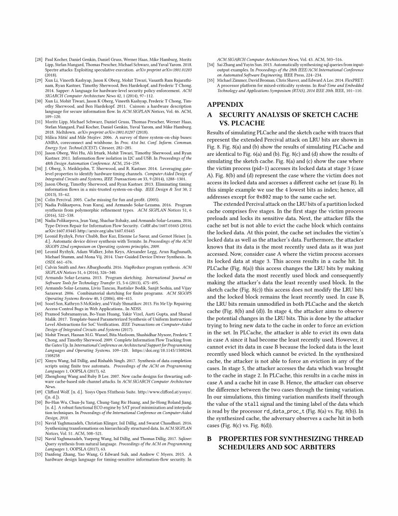
[28] Paul Kocher, Daniel Genkin, Daniel Gruss, Werner Haas, Mike Hamburg, MoritzLipp, StefanMangard, Thomas Prescher, Michael Schwarz, and Yuval Yarom. 2018.Spectre attacks: Exploiting speculative execution. arXiv preprint arXiv:1801.01203(2018).
[29] Xun Li, Vineeth Kashyap, Jason K Oberg, Mohit Tiwari, Vasanth Ram Rajarathi-nam, Ryan Kastner, Timothy Sherwood, Ben Hardekopf, and Frederic T Chong.2014. Sapper: A language for hardware-level security policy enforcement. ACMSIGARCH Computer Architecture News 42, 1 (2014), 97–112.
[30] Xun Li, Mohit Tiwari, Jason K Oberg, Vineeth Kashyap, Frederic T Chong, Tim-othy Sherwood, and Ben Hardekopf. 2011. Caisson: a hardware descriptionlanguage for secure information flow. In ACM SIGPLAN Notices, Vol. 46. ACM,109–120.
[31] Moritz Lipp, Michael Schwarz, Daniel Gruss, Thomas Prescher, Werner Haas,Stefan Mangard, Paul Kocher, Daniel Genkin, Yuval Yarom, and Mike Hamburg.2018. Meltdown. arXiv preprint arXiv:1801.01207 (2018).
[32] Milica Mitić and Mile Stojčev. 2006. A survey of three system-on-chip buses:AMBA, coreconnect and wishbone. In Proc. 41st Int. Conf. Inform. Commun.Energy Syst. Technol.(ICEST). Citeseer, 282–285.
[33] Jason Oberg, Wei Hu, Ali Irturk, Mohit Tiwari, Timothy Sherwood, and RyanKastner. 2011. Information flow isolation in I2C and USB. In Proceedings of the48th Design Automation Conference. ACM, 254–259.
[34] J. Oberg, S. Meiklejohn, T. Sherwood, and R. Kastner. 2014. Leveraging gate-level properties to identify hardware timing channels. Computer-Aided Design ofIntegrated Circuits and Systems, IEEE Transactions on 33, 9 (2014), 1288–1301.
[35] Jason Oberg, Timothy Sherwood, and Ryan Kastner. 2013. Eliminating timinginformation flows in a mix-trusted system-on-chip. IEEE Design & Test 30, 2(2013), 55–62.
[36] Colin Percival. 2005. Cache missing for fun and profit. (2005).[37] Nadia Polikarpova, Ivan Kuraj, and Armando Solar-Lezama. 2016. Program
synthesis from polymorphic refinement types. ACM SIGPLAN Notices 51, 6(2016), 522–538.
[38] Nadia Polikarpova, Jean Yang, Shachar Itzhaky, and Armando Solar-Lezama. 2016.Type-Driven Repair for Information Flow Security. CoRR abs/1607.03445 (2016).arXiv:1607.03445 http://arxiv.org/abs/1607.03445
[39] Leonid Ryzhyk, Peter Chubb, Ihor Kuz, Etienne Le Sueur, and Gernot Heiser. [n.d.]. Automatic device driver synthesis with Termite. In Proceedings of the ACMSIGOPS 22nd symposium on Operating systems principles, 2009.
[40] Leonid Ryzhyk, Adam Walker, John Keys, Alexander Legg, Arun Raghunath,Michael Stumm, and Mona Vij. 2014. User-Guided Device Driver Synthesis.. InOSDI. 661–676.
[41] Calvin Smith and Aws Albarghouthi. 2016. MapReduce program synthesis. ACMSIGPLAN Notices 51, 6 (2016), 326–340.
[42] Armando Solar-Lezama. 2013. Program sketching. International Journal onSoftware Tools for Technology Transfer 15, 5-6 (2013), 475–495.
[43] Armando Solar-Lezama, Liviu Tancau, Rastislav Bodik, Sanjit Seshia, and VijaySaraswat. 2006. Combinatorial sketching for finite programs. ACM SIGOPSOperating Systems Review 40, 5 (2006), 404–415.
[44] Sooel Son, Kathryn S McKinley, and Vitaly Shmatikov. 2013. Fix Me Up: RepairingAccess-Control Bugs in Web Applications.. In NDSS.
[45] Pramod Subramanyan, Bo-Yuan Huang, Yakir Vizel, Aarti Gupta, and SharadMalik. 2017. Template-based Parameterized Synthesis of Uniform Instruction-Level Abstractions for SoC Verification. IEEE Transactions on Computer-AidedDesign of Integrated Circuits and Systems (2017).
[46] Mohit Tiwari, Hassan M.G. Wassel, Bita Mazloom, Shashidhar Mysore, Frederic T.Chong, and Timothy Sherwood. 2009. Complete Information Flow Tracking fromthe Gates Up. In International Conference on Architectural Support for ProgrammingLanguages and Operating Systems. 109–120. https://doi.org/10.1145/1508244.1508258
[47] Xinyu Wang, Isil Dillig, and Rishabh Singh. 2017. Synthesis of data completionscripts using finite tree automata. Proceedings of the ACM on ProgrammingLanguages 1, OOPSLA (2017), 62.
[48] Zhenghong Wang and Ruby B Lee. 2007. New cache designs for thwarting soft-ware cache-based side channel attacks. In ACM SIGARCH Computer ArchitectureNews.
[49] Clifford Wolf. [n. d.]. Yosys Open SYnthesis Suite. http://www.clifford.at/yosys/.([n. d.]).
[50] Bo-Han Wu, Chun-Ju Yang, Chung-Yang Ric Huang, and Jie-Hong Roland Jiang.[n. d.]. A robust functional ECO engine by SAT proof minimization and interpola-tion techniques. In Proceedings of the International Conference on Computer-AidedDesign, 2010.
[51] Navid Yaghmazadeh, Christian Klinger, Isil Dillig, and Swarat Chaudhuri. 2016.Synthesizing transformations on hierarchically structured data. In ACM SIGPLANNotices, Vol. 51. ACM, 508–521.
[52] Navid Yaghmazadeh, Yuepeng Wang, Isil Dillig, and Thomas Dillig. 2017. Sqlizer:Query synthesis from natural language. Proceedings of the ACM on ProgrammingLanguages 1, OOPSLA (2017), 63.
[53] Danfeng Zhang, Yao Wang, G Edward Suh, and Andrew C Myers. 2015. Ahardware design language for timing-sensitive information-flow security. In
ACM SIGARCH Computer Architecture News, Vol. 43. ACM, 503–516.[54] Sai Zhang and Yuyin Sun. 2013. Automatically synthesizing sql queries from input-
output examples. In Proceedings of the 28th IEEE/ACM International Conferenceon Automated Software Engineering. IEEE Press, 224–234.
[55] Michael Zimmer, David Broman, Chris Shaver, and Edward A Lee. 2014. FlexPRET:A processor platform for mixed-criticality systems. In Real-Time and EmbeddedTechnology and Applications Symposium (RTAS), 2014 IEEE 20th. IEEE, 101–110.
APPENDIXA SECURITY ANALYSIS OF SKETCH CACHE
VS. PLCACHEResults of simulating PLCache and the sketch cache with traces thatrepresent the extended Percival attack on LRU bits are shown inFig. 8. Fig. 8(a) and (b) show the results of simulating PLCache andare identical to Fig. 6(a) and (b). Fig. 8(c) and (d) show the results ofsimulating the sketch cache. Fig. 8(a) and (c) show the case wherethe victim process (pid=1) accesses its locked data at stage 3 (caseA). Fig. 8(b) and (d) represent the case where the victim does notaccess its locked data and accesses a different cache set (case B). Inthis simple example we use the 4 lowest bits as index; hence, alladdresses except for 0x802 map to the same cache set.
The extended Percival attack on the LRU bits of a partition lockedcache comprises five stages. In the first stage the victim processpreloads and locks its sensitive data. Next, the attacker fills thecache set but is not able to evict the cache block which containsthe locked data. At this point, the cache set includes the victim’slocked data as well as the attacker’s data. Furthermore, the attackerknows that its data is the most recently used data as it was justaccessed. Now, consider case A where the victim process accessesits locked data at stage 3. This access results in a cache hit. InPLCache (Fig. 8(a)) this access changes the LRU bits by makingthe locked data the most recently used block and consequentlymaking the attacker’s data the least recently used block. In thesketch cache (Fig. 8(c)) this access does not modify the LRU bitsand the locked block remains the least recently used. In case B,the LRU bits remain unmodified in both PLCache and the sketchcache (Fig. 8(b) and (d)). In stage 4, the attacker aims to observethe potential changes in the LRU bits. This is done by the attackertrying to bring new data to the cache in order to force an evictionin the set. In PLCache, the attacker is able to evict its own datain case A since it had become the least recently used. However, itcannot evict its data in case B because the locked data is the leastrecently used block which cannot be evicted. In the synthesizedcache, the attacker is not able to force an eviction in any of thecases. In stage 5, the attacker accesses the data which was broughtto the cache in stage 2. In PLCache, this results in a cache miss incase A and a cache hit in case B. Hence, the attacker can observethe difference between the two cases through the timing variation.In our simulations, this timing variation manifests itself throughthe value of the stall signal and the timing label of the data whichis read by the processor rd_data_proc_t (Fig. 8(a) vs. Fig. 8(b)). Inthe synthesized cache, the adversary observes a cache hit in bothcases (Fig. 8(c) vs. Fig. 8(d)).
B PROPERTIES FOR SYNTHESIZING THREADSCHEDULERS AND SOC ARBITERS
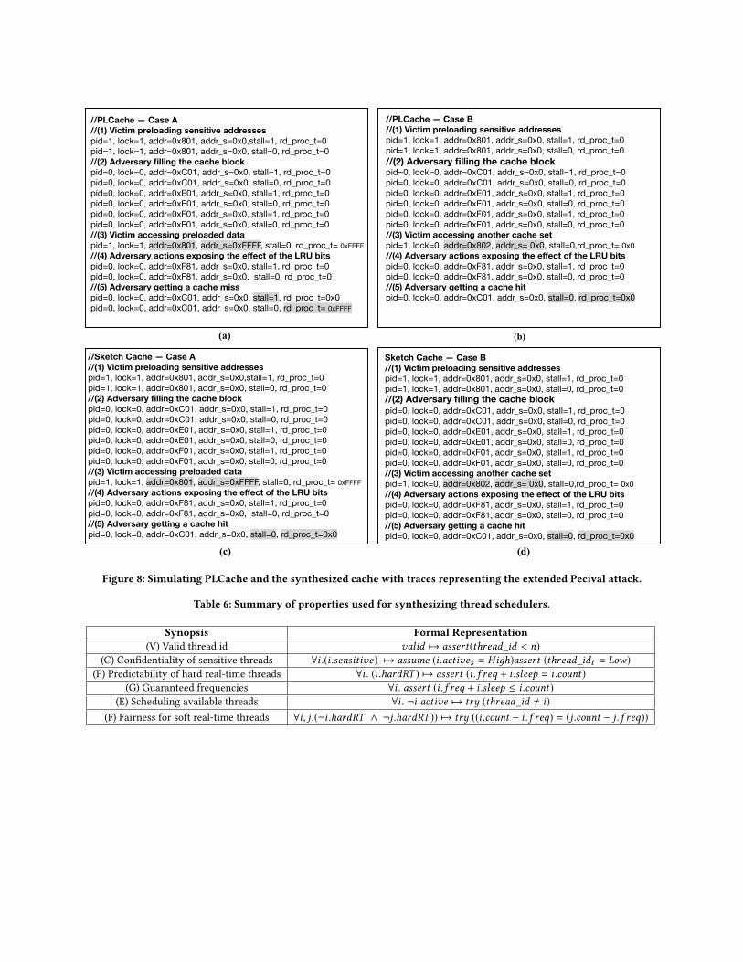
//Sketch Cache — Case A //(1) Victim preloading sensitive addresses pid=1, lock=1, addr=0x801, addr_s=0x0,stall=1, rd_proc_t=0pid=1, lock=1, addr=0x801, addr_s=0x0, stall=0, rd_proc_t=0//(2) Adversary filling the cache block pid=0, lock=0, addr=0xC01, addr_s=0x0, stall=1, rd_proc_t=0pid=0, lock=0, addr=0xC01, addr_s=0x0, stall=0, rd_proc_t=0pid=0, lock=0, addr=0xE01, addr_s=0x0, stall=1, rd_proc_t=0pid=0, lock=0, addr=0xE01, addr_s=0x0, stall=0, rd_proc_t=0pid=0, lock=0, addr=0xF01, addr_s=0x0, stall=1, rd_proc_t=0pid=0, lock=0, addr=0xF01, addr_s=0x0, stall=0, rd_proc_t=0//(3) Victim accessing preloaded data pid=1, lock=1, addr=0x801, addr_s=0xFFFF, stall=0, rd_proc_t= 0xFFFF//(4) Adversary actions exposing the effect of the LRU bits pid=0, lock=0, addr=0xF81, addr_s=0x0, stall=1, rd_proc_t=0pid=0, lock=0, addr=0xF81, addr_s=0x0, stall=0, rd_proc_t=0//(5) Adversary getting a cache hit pid=0, lock=0, addr=0xC01, addr_s=0x0, stall=0, rd_proc_t=0x0
Sketch Cache — Case B //(1) Victim preloading sensitive addresses pid=1, lock=1, addr=0x801, addr_s=0x0, stall=1, rd_proc_t=0pid=1, lock=1, addr=0x801, addr_s=0x0, stall=0, rd_proc_t=0//(2) Adversary filling the cache block pid=0, lock=0, addr=0xC01, addr_s=0x0, stall=1, rd_proc_t=0pid=0, lock=0, addr=0xC01, addr_s=0x0, stall=0, rd_proc_t=0pid=0, lock=0, addr=0xE01, addr_s=0x0, stall=1, rd_proc_t=0pid=0, lock=0, addr=0xE01, addr_s=0x0, stall=0, rd_proc_t=0pid=0, lock=0, addr=0xF01, addr_s=0x0, stall=1, rd_proc_t=0pid=0, lock=0, addr=0xF01, addr_s=0x0, stall=0, rd_proc_t=0//(3) Victim accessing another cache set pid=1, lock=0, addr=0x802, addr_s= 0x0, stall=0,rd_proc_t= 0x0//(4) Adversary actions exposing the effect of the LRU bits pid=0, lock=0, addr=0xF81, addr_s=0x0, stall=1, rd_proc_t=0pid=0, lock=0, addr=0xF81, addr_s=0x0, stall=0, rd_proc_t=0//(5) Adversary getting a cache hit pid=0, lock=0, addr=0xC01, addr_s=0x0, stall=0, rd_proc_t=0x0
(c) (d)
//PLCache — Case A //(1) Victim preloading sensitive addresses pid=1, lock=1, addr=0x801, addr_s=0x0,stall=1, rd_proc_t=0pid=1, lock=1, addr=0x801, addr_s=0x0, stall=0, rd_proc_t=0//(2) Adversary filling the cache block pid=0, lock=0, addr=0xC01, addr_s=0x0, stall=1, rd_proc_t=0pid=0, lock=0, addr=0xC01, addr_s=0x0, stall=0, rd_proc_t=0pid=0, lock=0, addr=0xE01, addr_s=0x0, stall=1, rd_proc_t=0pid=0, lock=0, addr=0xE01, addr_s=0x0, stall=0, rd_proc_t=0pid=0, lock=0, addr=0xF01, addr_s=0x0, stall=1, rd_proc_t=0pid=0, lock=0, addr=0xF01, addr_s=0x0, stall=0, rd_proc_t=0//(3) Victim accessing preloaded data pid=1, lock=1, addr=0x801, addr_s=0xFFFF, stall=0, rd_proc_t= 0xFFFF//(4) Adversary actions exposing the effect of the LRU bits pid=0, lock=0, addr=0xF81, addr_s=0x0, stall=1, rd_proc_t=0pid=0, lock=0, addr=0xF81, addr_s=0x0, stall=0, rd_proc_t=0//(5) Adversary getting a cache miss pid=0, lock=0, addr=0xC01, addr_s=0x0, stall=1, rd_proc_t=0x0pid=0, lock=0, addr=0xC01, addr_s=0x0, stall=0, rd_proc_t= 0xFFFF
//PLCache — Case B //(1) Victim preloading sensitive addresses pid=1, lock=1, addr=0x801, addr_s=0x0, stall=1, rd_proc_t=0pid=1, lock=1, addr=0x801, addr_s=0x0, stall=0, rd_proc_t=0//(2) Adversary filling the cache block pid=0, lock=0, addr=0xC01, addr_s=0x0, stall=1, rd_proc_t=0pid=0, lock=0, addr=0xC01, addr_s=0x0, stall=0, rd_proc_t=0pid=0, lock=0, addr=0xE01, addr_s=0x0, stall=1, rd_proc_t=0pid=0, lock=0, addr=0xE01, addr_s=0x0, stall=0, rd_proc_t=0pid=0, lock=0, addr=0xF01, addr_s=0x0, stall=1, rd_proc_t=0pid=0, lock=0, addr=0xF01, addr_s=0x0, stall=0, rd_proc_t=0//(3) Victim accessing another cache set pid=1, lock=0, addr=0x802, addr_s= 0x0, stall=0,rd_proc_t= 0x0//(4) Adversary actions exposing the effect of the LRU bits pid=0, lock=0, addr=0xF81, addr_s=0x0, stall=1, rd_proc_t=0pid=0, lock=0, addr=0xF81, addr_s=0x0, stall=0, rd_proc_t=0//(5) Adversary getting a cache hit pid=0, lock=0, addr=0xC01, addr_s=0x0, stall=0, rd_proc_t=0x0
(a) (b)
Figure 8: Simulating PLCache and the synthesized cache with traces representing the extended Pecival attack.
Table 6: Summary of properties used for synthesizing thread schedulers.
Synopsis Formal Representation(V) Valid thread id valid 7→ assert(thread_id < n)
(C) Confidentiality of sensitive threads ∀i .(i .sensitive) 7→ assume (i .actives = Hiдh)assert (thread_idt = Low)
(P) Predictability of hard real-time threads ∀i . (i .hardRT ) 7→ assert (i . f req + i .sleep = i .count)
(G) Guaranteed frequencies ∀i . assert (i . f req + i .sleep ≤ i .count)
(E) Scheduling available threads ∀i . ¬i .active 7→ try (thread_id , i)(F) Fairness for soft real-time threads ∀i, j .(¬i .hardRT ∧ ¬j .hardRT )) 7→ try ((i .count − i . f req) = (j .count − j . f req))
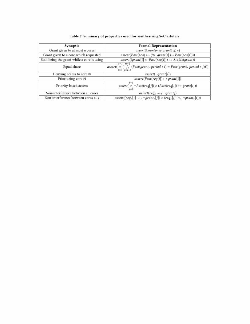
Table 7: Summary of properties used for synthesizing SoC arbiters.
Synopsis Formal RepresentationGrant given to at most n cores assert(Countones(дrant) ≤ n)
Grant given to a core which requested assert(Past(req) 7→ (∀i . дrant[i] 7→ Past(req[i])))
Stabilizing the grant while a core is using assert((дrant[i] ∧ Past(req[i])) 7→ Stable(дrant))
Equal share assert(n−1∧i=0(n−2∧j=i+1(Past(дrant , period ∗ i) = Past(дrant , period ∗ j))))
Denying access to core #i assert(¬дrant[i])
Prioritizing core #i assert(Past(req[i]) 7→ дrant[i])
Priority-based access assert(i−1∧j=0¬Past(req[j]) ∧ (Past(req[i]) 7→ дrant[i]))
Non-interference between all cores assert(reqs ↛t ¬дrants )
Non-interference between cores #i, j assert((reqs [i]↛t ¬дrants [j]) ∧ (reqs [j]↛t ¬дrants [i]))