verlag moderne industrie technical elastomers - fst.com-d-,com/products/material...
TRANSCRIPT

VERLAG MODERNE INDUSTRIE
Technical Elastomers
Tec
hn
ica
l Ela
sto
me
rs
The basis of high-tech sealing andvibration control technology solutions
Freudenberg Sealing Technologies

verlag moderne industrie
Technical Elastomers
The basis of high-tech sealing and vibration control technology solutions
Meike Rinnbauer
ContentElastomer development 4From natural rubber to high-tech material .............................................. 4Basic principles ....................................................................................... 5
Elastomers and their properties 9The viscoelastic behavior of elastomers.................................................. 9The correlation between frequency and temperature .............................. 12The systematization of elastomers .......................................................... 13
Factors that influence material behavior 16Compound ingredients ............................................................................ 16The influence of the cross-link density ................................................... 19Physical and chemical action .................................................................. 22
Processing techniques 30Mixing technology .................................................................................. 30Molding processes................................................................................... 37Optimizing elastomer processing procedures ......................................... 43
Testing elastomers 46Testing during the production process..................................................... 46Estimating the working life ..................................................................... 48Component simulation using FEM ......................................................... 49
High-tech products made of technical elastomers 52
Outlook 63
Glossary 66
Bibliography 67
Appendix 68
The company behind this book 71
This book was produced with the technical collaboration of Freudenberg Sealing Technologies GmbH & Co. KG.
Translation: Flanagan Language Services, Aingeal Flanagan, Köln
© 2007 All rights reserved withsv corporate media GmbH, D-80992 Munich, Germanywww.sv-corporate-media.de
First published in Germany in the seriesDie Bibliothek der TechnikOriginal title: Technische Elastomerwerkstoffe© 2006 by sv corporate media GmbH
Illustrations: Freudenberg Sealing Technologies GmbH & Co. KG, WeinheimTypesetting: abavo GmbH, D-86807 BuchloePrinting and binding: Sellier Druck GmbH, D-85354 Freising
Basic principles 5
ogy. The increasing multi-functionality ofmodern elastomeric components means thatexpertise and a wealth of experience areneeded for targeted elastomeric development.
Basic principlesPolymers are very large molecules that areformed by the linkage of a large number ofvery small structural units (monomers). Themonomers are linked by means of functional,reactive groups, thereby creating compositesthat exhibit completely different properties tothe starting materials. The molecular structureof polymers can be linear, branched, or cross-linked. Depending on the orientation of themolecule chains, a differentiation is made be-tween polymers in an amorphous and a par-tially crystalline state. The degree of poly-merization – i.e. the number of monomers ina polymer chain – has a significant influenceon the mechanical properties of the polymers.As the crystallinity or density of the polymer
4
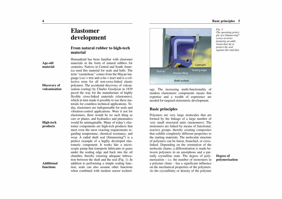
Elastomer developmentFrom natural rubber to high-techmaterialHumankind has been familiar with elastomermaterials in the form of natural rubbers forcenturies. Natives in Central and South Amer-ica used this material for seals and balls. Theterm “caoutchouc” comes from the Mayan lan-guage (cao = tree and ochu = tear) and is a col-lective term for all non-cross-linked elasticpolymers. The accidental discovery of vulcan-ization (curing) by Charles Goodyear in 1839paved the way for the manufacture of highlyflexible cross-linked materials (elastomers),which in turn made it possible to use these ma-terials for countless technical applications. To-day, elastomers are indispensable for seals andvibration-control applications. Were it not forelastomers, there would be no such thing ascars or planes, and hydraulics and pneumaticswould be unimaginable. Many of today’s elas-tomer components are high-tech products thatmeet even the most exacting requirements re-garding temperature, chemical resistance, andwear. A radial shaft seal (Simmerring®) is aperfect example of a highly developed elas-tomeric component. It works like a micro-scopic pump that transports lubricants or gasesunder the sealing edge and back into the oilchamber, thereby ensuring adequate lubrica-tion between the shaft and the seal (Fig. 1). Inaddition to performing a simple sealing func-tion, seals can also assume other functionswhen combined with modern sensor technol-
Fig. 1:The operating princi-ple of a Simmerring®
(cross-section) featuring an addi-tional dust lip to protect the sealagainst dirt and dust
Shaft surface
Lubricant
Sealing edgeGrease fillingDust lip
Age-old material
Discovery of vulcanization
High-tech products
Additional functions
Degree of polymerization
Basic principles 7
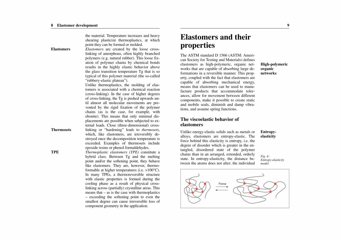
Polymer materials are categorized according totheir structure, their mechanical deformationbehavior and, correspondingly, their propertiesand areas of application (Fig. 3). Thermoplas-tics are made up of long and linear or looselybranched polymers that are not cross-linked.At room temperature they are in a state that issomewhere between glassy and ductile. Ther-moplastics can have amorphous or partiallycrystalline structures. In amorphous thermo-plastics, the polymer chains are arranged in arandom manner both in the molten and in thesolid state. Partially crystalline thermoplasticsare amorphous in the molten state. However,when solid, there are areas in which the poly-mer chains are arranged parallel to one an-other. The degree of crystallinity has a signifi-cant influence on the mechanical properties of
6 Elastomer development
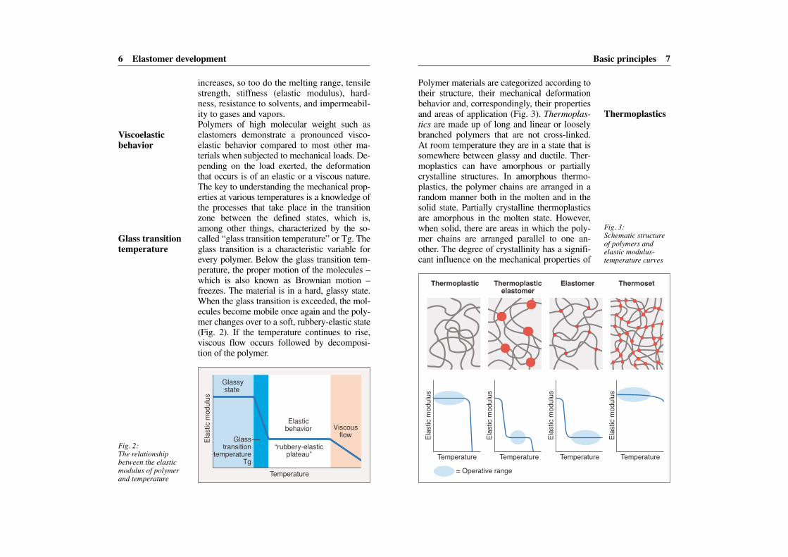
increases, so too do the melting range, tensilestrength, stiffness (elastic modulus), hard-ness, resistance to solvents, and impermeabil-ity to gases and vapors.Polymers of high molecular weight such aselastomers demonstrate a pronounced visco -elastic behavior compared to most other ma-terials when subjected to mechanical loads. De-pending on the load exerted, the deformationthat occurs is of an elastic or a viscous nature.The key to understanding the mechanical prop-erties at various temperatures is a knowledge ofthe processes that take place in the transitionzone between the defined states, which is,among other things, characterized by the so-called “glass transition temperature” or Tg. Theglass transition is a characteristic variable forevery polymer. Below the glass transition tem-perature, the proper motion of the molecules –which is also known as Brownian motion –freezes. The material is in a hard, glassy state.When the glass transition is exceeded, the mol-ecules become mobile once again and the poly-mer changes over to a soft, rubbery-elastic state(Fig. 2). If the temperature continues to rise,viscous flow occurs followed by decomposi-tion of the polymer.
Temperature
“rubbery-elastic plateau”
Ela
stic
mod
ulus
Viscous flow
Elastic behavior
Glassy state
Glass transition
temperature Tg
Fig. 2:The relationship between the elasticmodulus of polymerand temperature
Fig. 3:Schematic structureof polymers and elastic modulus-temperature curves
Elas
tic m
odulu
s
Elas
tic m
odulu
s
Elas
tic m
odulu
s
Elas
tic m
odulu
s
Thermoplastic Thermoplastic elastomer
Elastomer Thermoset
Temperature Temperature Temperature Temperature= Operative range
Viscoelastic behavior
Glass transitiontemperature
Thermoplastics
9
Elastomers and theirpropertiesThe ASTM standard D 1566 (ASTM: Ameri-can Society for Testing and Materials) defineselastomers as high-polymeric, organic net-works that are capable of absorbing large de-formations in a reversible manner. This prop-erty, coupled with the fact that elastomers arecapable of absorbing mechanical energy,means that elastomers can be used to manu-facture products that accommodate toler-ances, allow for movement between differentcomponents, make it possible to create staticand mobile seals, diminish and damp vibra-tions, and assume spring functions.
The viscoelastic behavior of elastomersUnlike energy-elastic solids such as metals oralloys, elastomers are entropy-elastic. Theforce behind this elasticity is entropy, i.e. thedegree of disorder which is greater in the en-tangled, disordered state of the polymerchains than in an arranged, extended, orderlystate. In entropy-elasticity, the distance be-tween the atoms does not alter; the individual
8 Elastomer development
the material. Temperature increases and heavyshearing plasticize thermoplastics, at whichpoint they can be formed or molded.Elastomers are created by the loose cross-linking of amorphous, often highly branchedpolymers (e.g. natural rubber). This loose fix-ation of polymer chains by chemical bondsresults in the highly elastic behavior abovethe glass transition temperature Tg that is sotypical of this polymer material (the so-called“rubbery-elastic plateau”).Unlike thermoplastics, the molding of elas-tomers is associated with a chemical reaction(cross-linking). In the case of higher degreesof cross-linking, the Tg is pushed upwards un-til almost all molecular movements are pre-vented by the rigid fixation of the polymerchains (as is the case, for example, withebonite). This means that only minimal dis-placements are possible when subjected to ex-ternal loads. Close (three-dimensional) cross-linking or “hardening” leads to thermosets,which, like elastomers, are irreversibly de-stroyed once the decomposition temperature isexceeded. Examples of thermosets includeepoxide resins or phenol formaldehydes.Thermoplastic elastomers (TPE) constitute ahybrid class. Between Tg and the meltingpoint and/or the softening point, they behavelike elastomers. They are, however, thermo-formable at higher temperatures (i.e. >100°C).In many TPEs, a thermoreversible structurewith elastic properties is formed during thecooling phase as a result of physical cross-linking across (partially) crystalline areas. Thismeans that – as is the case with thermoplastics– exceeding the softening point to even thesmallest degree can cause irreversible loss ofcomponent geometry in the application.
Fig. 4:Entropy-elasticitymodel
Force
Elastomers
Thermosets
TPE
High-polymericorganic networks
Entropy-elasticity
The viscoelastic behavior of elastomers 11
to creep, stress relaxation, or cold flow. Vis-cous flow can be suppressed to a great degreeby fixing the chains to one another (cross-linking). In other words, loose cross-linkingultimately causes typical rubbery-elastic (elas-tomeric) behavior. The viscoelasticity of elas-tomers results in a pronounced time- and tem-perature-dependency for a large number ofphysical and in particular mechanical proper-ties. In the case of steel, for example, there isa linear relationship between stress and strain,whereas with elastomer, there is a non-linearrelationship between the two. This non-linearrelationship is demonstrated among otherthings by the elastomer’s dependency on thedeformation speed (Fig. 6).The consequence of this dependency is thatelastomers react with great sensitivity tochanges in test conditions. This is why prob-lems are frequently encountered in practicaloperation when correlating simple physicaltest results with the actual prevailing loads ex-erted on an elastomer component in the instal-lation space (the complex of loads acting onthe component). This means that it is ab-solutely essential for exact specifications to be
10 Elastomers and their properties
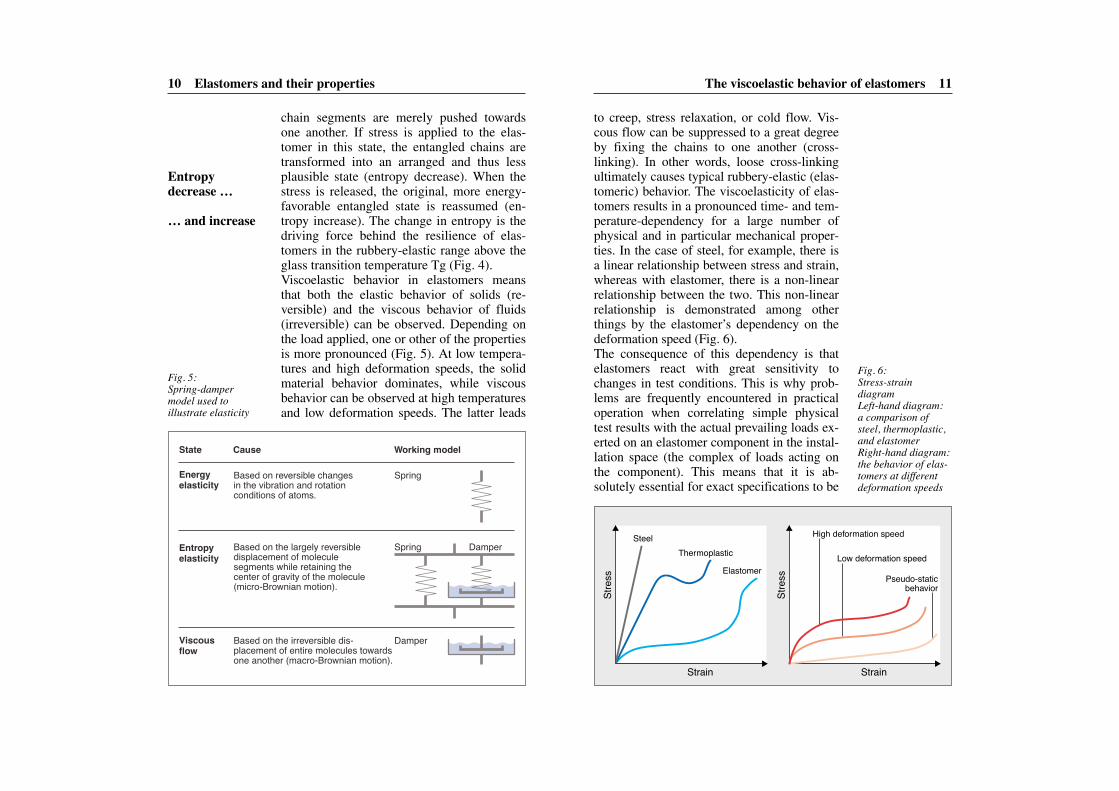
chain segments are merely pushed towardsone another. If stress is applied to the elas-tomer in this state, the entangled chains aretransformed into an arranged and thus lessplausible state (entropy decrease). When thestress is released, the original, more energy-favorable entangled state is reassumed (en-tropy increase). The change in entropy is thedriving force behind the resilience of elas-tomers in the rubbery-elastic range above theglass transition temperature Tg (Fig. 4).Viscoelastic behavior in elastomers meansthat both the elastic behavior of solids (re-versible) and the viscous behavior of fluids(irreversible) can be observed. Depending onthe load applied, one or other of the propertiesis more pronounced (Fig. 5). At low tempera-tures and high deformation speeds, the solidmaterial behavior dominates, while viscousbehavior can be observed at high temperaturesand low deformation speeds. The latter leads
Fig. 5:Spring-dampermodel used to illustrate elasticity
Based on reversible changes in the vibration and rotation conditions of atoms.
Based on the largely reversible displacement of molecule segments while retaining the center of gravity of the molecule (micro-Brownian motion).
Based on the irreversible dis- placement of entire molecules towards one another (macro-Brownian motion).
Spring
Spring Damper
Damper
State
Energy elasticity
Entropy elasticity
Viscous flow
Cause Working model
Fig. 6:Stress-strain diagramLeft-hand diagram: a comparison ofsteel, thermoplastic,and elastomerRight-hand diagram:the behavior of elas-tomers at differentdeformation speeds
Stre
ss
Stre
ss
Strain Strain
SteelThermoplastic
High deformation speed
Low deformation speed
Pseudo-static behavior
Elastomer
Entropy decrease …
… and increase
The systematization of elastomers 13
premature hardening of the material (increasein the dynamic modulus).This influence of relaxation, which dependson temperature and frequency, must thereforebe taken into account when designing compo-nents, especially dynamic seals.
The systematization of elastomersASTM D 1418 defines a systematization forelastomers and a set of abbreviations. The ab -
12 Elastomers and their properties
prepared for an elastomer component in orderto ensure that the most important properties ofthe product can be reproduced in tests.
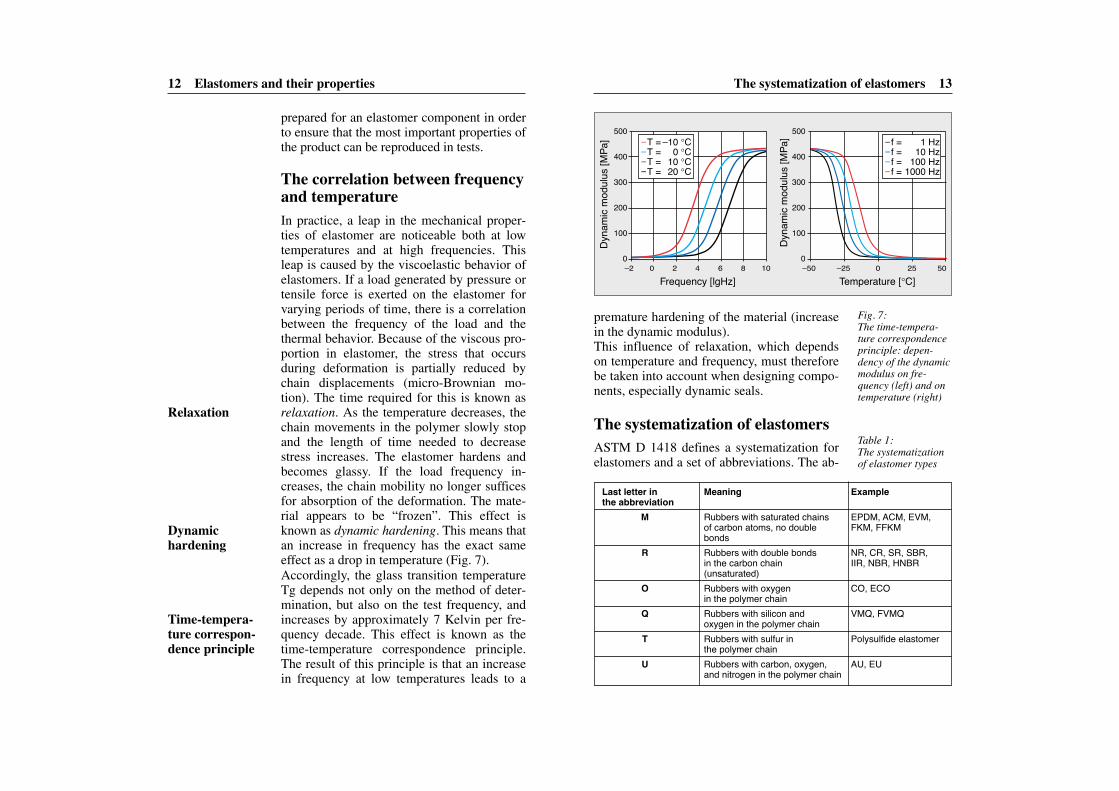
The correlation between frequencyand temperatureIn practice, a leap in the mechanical proper-ties of elastomer are noticeable both at lowtemperatures and at high frequencies. Thisleap is caused by the viscoelastic behavior ofelastomers. If a load generated by pressure ortensile force is exerted on the elastomer forvarying periods of time, there is a correlationbetween the frequency of the load and thethermal behavior. Because of the viscous pro-portion in elastomer, the stress that occursduring deformation is partially reduced bychain displacements (micro-Brownian mo-tion). The time required for this is known asrelaxation. As the temperature decreases, thechain movements in the polymer slowly stopand the length of time needed to decreasestress increases. The elastomer hardens andbecomes glassy. If the load frequency in-creases, the chain mobility no longer sufficesfor absorption of the deformation. The mate-rial appears to be “frozen”. This effect isknown as dynamic hardening. This means thatan increase in frequency has the exact sameeffect as a drop in temperature (Fig. 7).Accordingly, the glass transition temperatureTg depends not only on the method of deter-mination, but also on the test frequency, andincreases by approximately 7 Kelvin per fre-quency decade. This effect is known as thetime-temperature correspondence principle.The result of this principle is that an increasein frequency at low temperatures leads to a
Fig. 7:The time-tempera-ture correspondenceprinciple: depen-dency of the dynamicmodulus on fre-quency (left) and ontemperature (right)
Frequency [lgHz]
Dyna
mic
mod
ulus [
MPa
] T = –10 °CT = 0 °CT = 10 °CT = 20 °C
f = 1 Hzf = 10 Hzf = 100 Hzf = 1000 Hz
500
400
300
200
100
0–2
Temperature [°C]
Dyna
mic
mod
ulus [
MPa
] 500
400
300
200
100
0–50 –25 0 25 500 2 4 6 8 10
Last letter in Meaning Examplethe abbreviation
M Rubbers with saturated chains EPDM, ACM, EVM, of carbon atoms, no double FKM, FFKMbonds
R Rubbers with double bonds NR, CR, SR, SBR,in the carbon chain IIR, NBR, HNBR(unsaturated)
O Rubbers with oxygen CO, ECOin the polymer chain
Q Rubbers with silicon and VMQ, FVMQoxygen in the polymer chain
T Rubbers with sulfur in Polysulfide elastomerthe polymer chain
U Rubbers with carbon, oxygen, AU, EUand nitrogen in the polymer chain
Table 1:The systematizationof elastomer types
Relaxation
Dynamic hardening
Time-tempera-ture correspon-dence principle
The systematization of elastomers 15
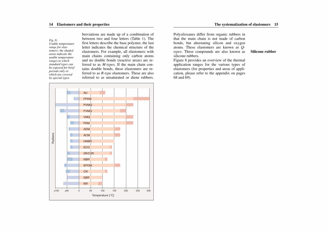
Polysiloxanes differ from organic rubbers inthat the main chain is not made of carbonbonds, but alternating silicon and oxygenatoms. These elastomers are known as Q-types. These compounds are also known assilicone rubbers.Figure 8 provides an overview of the thermalapplication ranges for the various types ofelastomers (for properties and areas of appli-cation, please refer to the appendix on pages68 and 69).
14 Elastomers and their properties
breviations are made up of a combination ofbetween two and four letters (Table 1). Thefirst letters describe the base polymer, the lastletter indicates the chemical structure of theelastomers. For example, all elastomers withmain chains containing only carbon atomsand no double bonds (reactive areas) are re-ferred to as M-types. If the main chain con-tains double bonds, these elastomers are re-ferred to as R-type elastomers. These are alsoreferred to as unsaturated or diene rubbers.
Rubb
ers
±100 ±50 0 50 100
Temperature [°C]
NR
SBR
CR
EPDM
NBR
IIR/CIIR
ECO
HNBR
ACM
AEM
FKM
VMQ
FVMQ
PVMQ
FFKM
AU
200 250 300150
Fig. 8:Usable temperaturerange for elas-tomers: the shadedareas indicate the usable temperatureranges to which standard types canbe exposed for brief periods only orwhich are covered by special types
Silicone rubber
Compound ingredients 17
The basic properties of an elastomeric com-pound are determined by the polymer and aredecisive for the performance of the seal. Forexample, although it is the polymer that de-termines the elastomer’s low-temperatureproperties, plasticizers can improve theseproperties within certain limits. However,when adding plasticizers, it is important totake into consideration that they can be ex-tracted from the elastomer through contactwith lubricating oils and can evaporate athigh temperatures. This is why it is importantat the development stage to take account ofthe operating conditions (e.g. temperatures)to which a seal will be exposed.So-called reinforcing fillers such as carbonblacks or silicas also have a significant influ-ence on the material properties of the elas-tomer. By varying the type and amount offillers used, the physical properties of theelastomer can be adapted to suit the intendedapplication. The specific surface, the struc-ture, and the surface activity of the fillerslargely determine the reinforcement effect.The principle is based on the interaction ofthe filler with the polymer matrix or – if thefiller content is sufficiently high – on the for-mation of filler networks that are superim-posed on the chemical polymer network. Re-inforcing fillers – in other words active fillers– have a particle diameter of between 10 and100 nm (nano particles); inactive fillers, onthe other hand, have a particle diameter of be-tween 500 and 1,000 nm. Carbon blacks areclassified using an ASTM code that charac-terizes the activity of the carbon blacks. Thesmaller the number, the greater the reinforc-ing effect of the carbon black. Because activecarbon blacks have a much greater influence
16
Factors that influencematerial behaviorElastomers are sensitive to light, ozone, hightemperatures, a large number of fluids andchemicals, and wear. This means that notonly the usable temperature range, but fre-quently also the elastomer’s chemical resis-tance and swelling behavior is of major sig-nificance when selecting a suitable sealingmaterial. It also explains why informationabout the range of application – e.g. the fluidor gaseous media with which the materialwill come in contact – plays a decisive role indetermining the functional capability of anelastomeric material. However, when devel-oping the elastomeric compound, not onlymust the chemical and physical factors of en-vironmental influences be taken into account,but also the processes of interaction that arecreated by the polymer and the compound in-gredients and which determine the overallphysical properties of the elastomer. To-gether, all of these factors have a significantinfluence on the life of the final component.
Compound ingredientsElastomers are multi-component systems inwhich each component has a very specificrole to play. When developing the compound,four main effects must be achieved: the rein-forcement of the elastomer by fillers, the im-provement of processability, the cross-linkingof rubber using curing agents, and the protec-tion of the elastomeric component againstdamaging external influences.
Knowledge ofthe range of application
Four main effects
Plasticizers
Reinforcingfillers
Active carbonblacks
The influence of the cross-link density 19
quality elastomeric product. This is why car-bon blacks that ensure good dispersibility andhigh processing reliability are now used inthe production of engineering elastomericmaterials.White fillers such as silicas exhibit similar re-inforcement potential to carbon blacks. How-ever, silicas have a marked tendency to ag-glomerate. They create strong filler networksthat are responsible for the reinforcement ef-fect in the polymer matrix. This is why com-pounds with active silicas are much more dif-ficult to process than compounds with thesame amount of carbon black fillers. More-over, because of their polarity, silicas disruptthe cross-linking with sulfur accelerator sys-tems, which in turn slows down the cross-linking process. Consequently, when replac-ing carbon blacks with silicas, the cross-link-ing chemistry must be adapted accordingly.
The influence of the cross-linkdensityCuring or cross-linking is the name given tothe production stage during which an elas-tomeric component is molded. During thisprocedure, chemical bonds are made thattransform the rubber compound into an elas-tomer with tailored properties. Curing gener-ally takes place under pressure and at in-creased temperatures (T >140°C) in speciallyconstructed tools.The cross-linking system determines the pro-cessing qualities, the chemical structure ofthe network, and the physical properties ofthe elastomers. This is why the cross-linkingsystem chosen during the development of theelastomer compound plays a decisive role in
18 Factors that influence material behavior
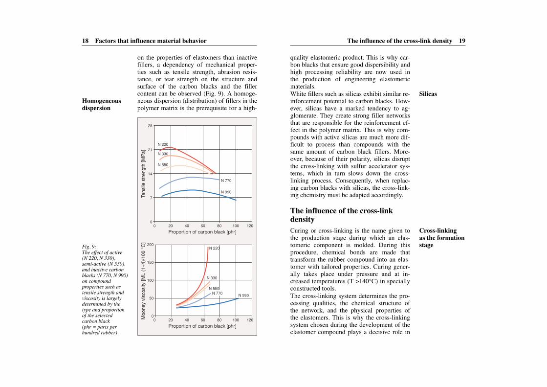
on the properties of elastomers than inactivefillers, a dependency of mechanical proper-ties such as tensile strength, abrasion resis-tance, or tear strength on the structure andsurface of the carbon blacks and the fillercontent can be observed (Fig. 9). A homoge-neous dispersion (distribution) of fillers in thepolymer matrix is the prerequisite for a high-
Proportion of carbon black [phr]
Tens
ile s
tren
gth
[MP
a]M
oone
y vi
scos
ity [M
L (1
+4)
/100
°C
]
N 770
N 990
N 220
N 330
N 550N 770 N 990
N 220
N 330
N 550
00
7
14
21
28
20 40 60 80 100 120
Proportion of carbon black [phr]0
0
50
100
150
200
20 40 60 80 100 120
Fig. 9:The effect of active(N 220, N 330),semi-active (N 550),and inactive carbonblacks (N 770, N 990)on compoundproperties such astensile strength andviscosity is largelydetermined by thetype and proportionof the selected carbon black (phr = parts per hundred rubber).
Homogeneousdispersion
Silicas
Cross-linking as the formationstage
The influence of the cross-link density 21
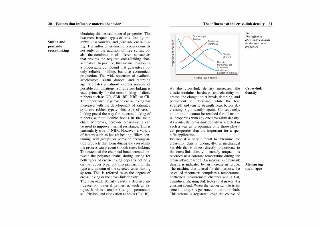
As the cross-link density increases, the elastic modulus, hardness, and elasticity in-crease, the elongation at break, damping, andpermanent set decrease, while the tearstrength and tensile strength peak before de-creasing significantly again. Consequently,an optimum cannot be reached for all mater-ial properties with any one cross-link density.As a rule, the cross-link density is selected insuch a way as to optimize only those physi-cal properties that are important for a spe-cific application.Because it is very difficult to determine thecross-link density chemically, a mechanicalvariable that is almost directly proportional tothe cross-link density – namely torque – isrecorded at a constant temperature during thecross-linking reaction. An increase in cross-linkdensity is indicated by an increase in torque.The machine that is used for this purpose, theso-called rheometer, comprises a temperature-controlled measurement chamber and a flat,cylindrical shearing disk (rotor) that moves at aconstant speed. When the rubber sample is in-serted, a torque is generated at the rotor shaft.This torque is registered over the course of
20 Factors that influence material behavior
obtaining the desired material properties. Thetwo most frequent types of cross-linking are:sulfur cross-linking and peroxide cross-link-ing. The sulfur cross-linking process consistsnot only of the addition of free sulfur, butalso the combination of different substancesthat ensures the required cross-linking char-acteristics. In practice, this means developinga processable compound that guarantees notonly reliable molding, but also economicalproduction. The wide spectrum of availableaccelerators, sulfur donors, and retardingagents creates an almost endless number ofpossible combinations. Sulfur cross-linking isused primarily for the cross-linking of dienerubbers such as NR, SBR, BR, NBR, or CR.The importance of peroxide cross-linking hasincreased with the development of saturatedsynthetic rubber types. This type of cross-linking paved the way for the cross-linking ofrubbers without double bonds in the mainchain. Moreover, peroxide cross-linking canbe used to improve thermal resistance. This isparticularly true of NBR. However, a varietyof factors such as hot-air heating, fillers con-taining acid groups, or peroxide decomposi-tion products that form during the cross-link-ing process can prevent smooth cross-linking.The extent of the chemical bonds created be-tween the polymer chains during curing forboth types of cross-linking depends not onlyon the rubber type, but also primarily on thetype and amount of the selected cross-linkingsystem. This is referred to as the degree ofcross-linking or the cross-link density.The cross-link density exerts a decisive in-fluence on material properties such as fa-tigue, hardness, tensile strength, permanentset, friction, and elongation at break (Fig. 10).
Prop
ertie
s of t
he cu
re
Cross-link density
Tear strengthFatigue
ResilienceHardness
Tensile strength
Damping Permanent setCoefficient of frictionElongation at break
Fig. 10:The influence of cross-link densityon the elastomerproperties
Sulfur and peroxide cross-linking
Cross-link density
Measuring the torque
Physical and chemical action 23
the loss of strength. These changes can takethe form of swelling, cracking, embrittle-ment, or discoloration of the elastomer. Anincrease in temperature accelerates the ageingprocesses considerably. The following rule ofthumb applies: for every 10°C increase intemperature, ageing accelerates by a factor of between 2 and 4. The life of the componentis shortened accordingly by the same factor.
Damage caused by oxygenSeals are exposed to a large number of envi-ronmental influences such as oxygen, ozone,UV light, or changing climatic conditions.The combination of oxygen in the air and in-creased temperatures damages the elastomermatrix. This damage can either lead to an ad-ditional cross-linking of polymer chains or adegradation of cross-linking points. These inturn lead to a loss of strength, hardening, orcharacteristic cracking, all of which can ulti-mately lead to the failure of the component.Diene rubbers such as NR, SBR, and NBRwhich still contain double bonds in the poly-mer chain are more sensitive to oxygen and,most particularly, ozone, than saturated rub-bers such as EPDM, ACM, ECO, etc.In order to retard or to halt the ageing processaltogether, antioxidants that have been se-lected to suit the elastomer type in questionare added to elastomer compounds (espe-cially diene rubbers). These antioxidantschemically neutralize the oxygen in the air sothat oxidation of the polymer chains is reli-ably prevented. Appropriate anti-ozonantsand waxes are used to prevent ozone-relateddamage. In the event of permanent deforma-tion – especially in the case of increased tem-peratures – chemical processes (chain degra-
22 Factors that influence material behavior
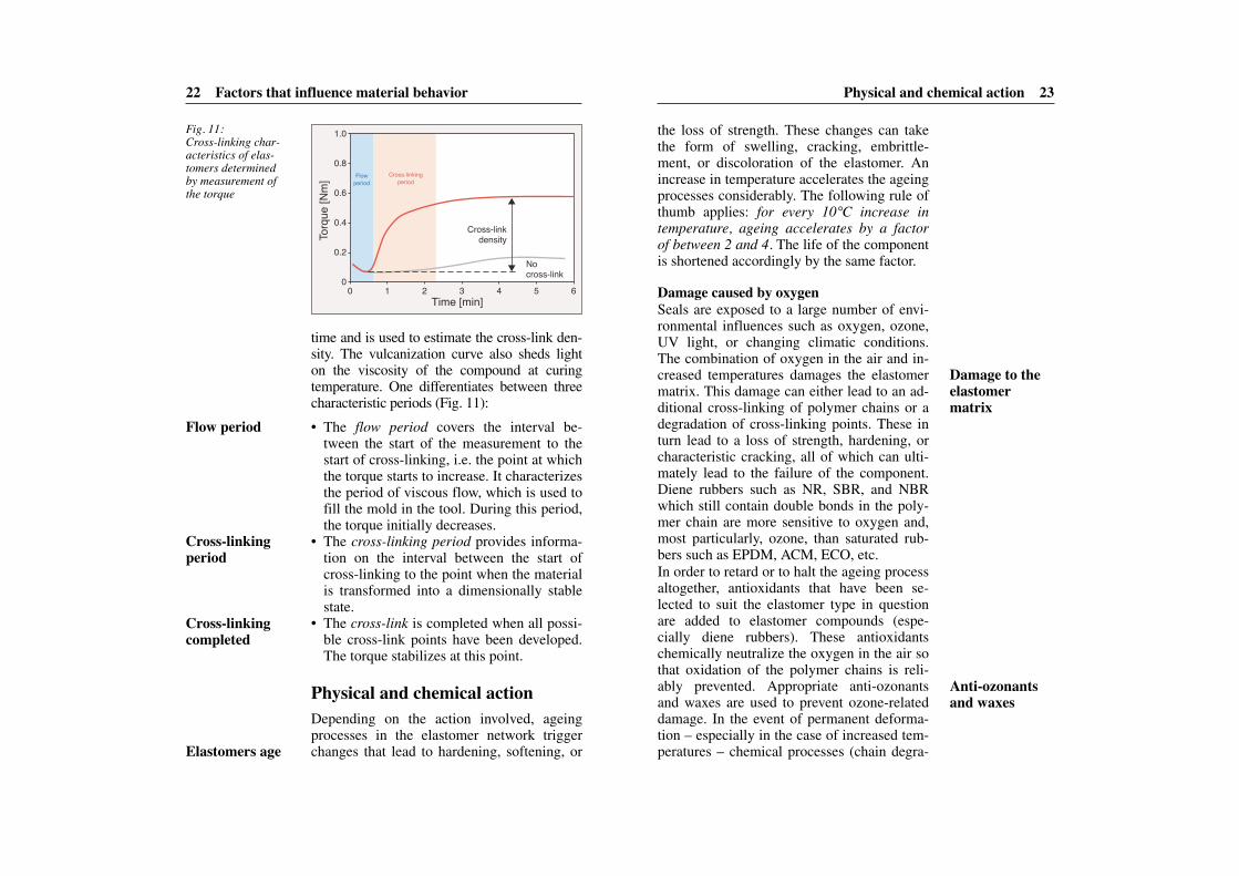
time and is used to estimate the cross-link den-sity. The vulcanization curve also sheds lighton the viscosity of the compound at curingtemperature. One differentiates between threecharacteristic periods (Fig. 11):
• The flow period covers the interval be-tween the start of the measurement to thestart of cross-linking, i.e. the point at whichthe torque starts to increase. It characterizesthe period of viscous flow, which is used tofill the mold in the tool. During this period,the torque initially decreases.
• The cross-linking period provides informa-tion on the interval between the start ofcross-linking to the point when the materialis transformed into a dimensionally stablestate.
• The cross-link is completed when all possi-ble cross-link points have been developed.The torque stabilizes at this point.
Physical and chemical actionDepending on the action involved, ageingprocesses in the elastomer network triggerchanges that lead to hardening, softening, or
00 1 2 3 4 5
Nocross-link
Cross-linkingperiod
Flowperiod
6
0.2
0.4
0.6
0.8
1.0
Time [min]To
rque
[Nm
]
Cross-linkdensity
Fig. 11:Cross-linking char-acteristics of elas-tomers determinedby measurement ofthe torque
Cross-linkingperiod
Flow period
Cross-linkingcompleted
Elastomers age
Damage to theelastomer matrix
Anti-ozonantsand waxes
Physical and chemical action 25
The best protection against ageing for anelastomer component depends largely on theoperating conditions for which the compo-nent is intended. Only in the most favorableof cases will a single antioxidant suffice. As arule, a combination of different antioxidantsis used.
The influence of the mediumWhenever media such as oils and greases actupon a material, two different processes oc-cur: physical swelling and chemical reaction.These processes can impair both the elas-tomer and its sealing function. The differencebetween the two processes is that in the latter,the influence of the media causes a chemicalreaction that irreversibly changes the chemi-cal structure of the material.In order to find out whether an elastomericmaterial is suitable for use in conjunctionwith a specific medium, it is stored in the
24 Factors that influence material behavior
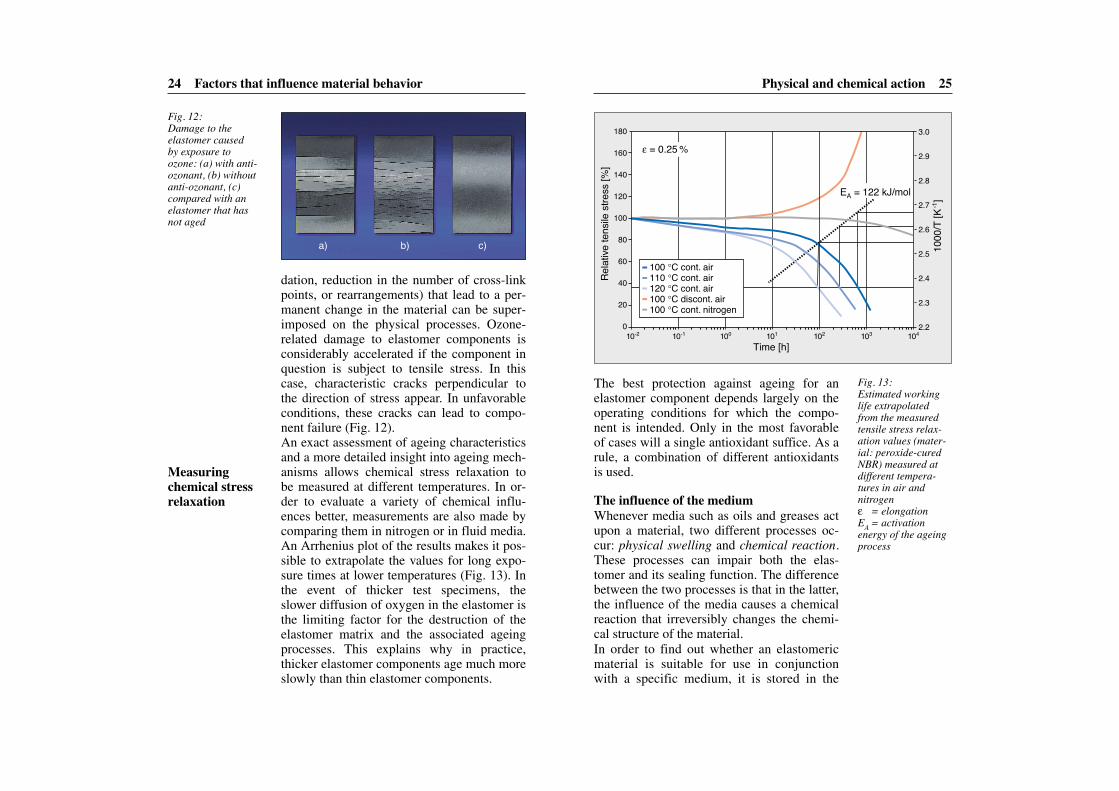
dation, reduction in the number of cross-linkpoints, or rearrangements) that lead to a per-manent change in the material can be super-imposed on the physical processes. Ozone-related damage to elastomer components isconsiderably accelerated if the component inquestion is subject to tensile stress. In thiscase, characteristic cracks perpendicular tothe direction of stress appear. In unfavorableconditions, these cracks can lead to compo-nent failure (Fig. 12).An exact assessment of ageing characteristicsand a more detailed insight into ageing mech-anisms allows chemical stress relaxation to be measured at different temperatures. In or-der to evaluate a variety of chemical influ-ences better, measurements are also made bycomparing them in nitrogen or in fluid media.An Arrhenius plot of the results makes it pos-sible to extrapolate the values for long expo-sure times at lower temperatures (Fig. 13). Inthe event of thicker test specimens, the slower diffusion of oxygen in the elastomer isthe limiting factor for the destruction of theelastomer matrix and the associated ageingprocesses. This explains why in practice,thicker elastomer components age much moreslowly than thin elastomer components.
Fig. 12:Damage to the elastomer caused by exposure toozone: (a) with anti-ozonant, (b) withoutanti-ozonant, (c)compared with anelastomer that hasnot aged
Fig. 13:Estimated workinglife extrapolated from the measuredtensile stress relax-ation values (mater-ial: peroxide-curedNBR) measured atdifferent tempera-tures in air and nitrogenε = elongationEA = activation energy of the ageingprocess
Time [h]
EA = 122 kJ/mol
ε = 0.25 %
100 °C cont. air 110 °C cont. air 120 °C cont. air 100 °C discont. air100 °C cont. nitrogen
010-2 10-1 100 101 102 103 104
2.2
2.3
2.4
2.5
2.6
2.7
2.8
2.9
3.0
20
40
60
80
100
120
140
160
180
Relat
ive te
nsile
stre
ss [%
]
1000
/T [K
-1]
a) b) c)
Measuringchemical stressrelaxation
Physical and chemical action 27
perature. This is why test runs under operat-ing conditions are an indispensable stepwhen evaluating a component. If the layoutof the sealing environment is suitable, minorvolume swelling does not pose a threat to thefunction of the elastomer seal. Volumeshrinkage, on the other hand, can impair thesealing function in that it can result in leak-age. Permeation occurs when the medium(gaseous or fluid) migrates through the ma-terial without penetrating the pores orcracks. This leads to micro leakage in theseal.The action of the media influences many ma-terial properties such as hardness, density,tear strength, and elongation as well as elec-trical and optical properties such as color andsurface structure. Consequently, the causes ofdamage are not necessarily exclusively attrib-utable to errors in seal production, but also toexternal influences such as the action of oils,greases, or gases which can change the elas-tomer both chemically and physically. In par-ticular, the high proportion of additives innew, fully synthetic oils can attack the sealingmaterial chemically and destroy it. This iswhy seal manufacturers must have a compre-hensive database of information that can beused to predict the performance and life spanof the seal as accurately as possible based oninterpretation of the interaction of the lubri-cant with the elastomer.There is no one elastomer that meets all requirements of oil resistance, thermal re -sistance, and low-temperature flexibilityequally. Consequently, it is essential to takeinto account both the surrounding mediumand the temperature conditions in the in-tended application when selecting a suitable
26 Factors that influence material behavior
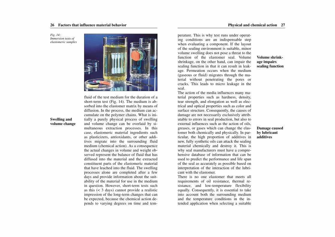
fluid of the test medium for the duration of ashort-term test (Fig. 14). The medium is ab-sorbed into the elastomer matrix by means ofdiffusion. In the process, the medium can ac-cumulate on the polymer chains. What is ini-tially a purely physical process of swellingand volume change can be overlaid by si-multaneous extraction processes. In thiscase, elastomeric material ingredients suchas plasticizers, antioxidants, or other addi-tives migrate into the surrounding fluidmedium (chemical action). As a consequencethe actual changes in volume and weight ob-served represent the balance of fluid that hasdiffused into the material and the extractedconstituent parts of the elastomeric materialthat have leached into the fluid. The swellingprocesses alone are completed after a fewdays and provide information about the suit-ability of the material for use in the mediumin question. However, short-term tests suchas this (< 3 days) cannot provide a realisticimpression of the long-term changes that canbe expected, because the chemical action de-pends to varying degrees on time and tem-
Fig. 14:Immersion tests ofelastomeric samples
Swelling andvolume change
Volume shrink-age impairs sealing function
Damage causedby lubricant additives
Physical and chemical action 29
tigue behavior of an elastomeric sealing mate-rial is of little use because both the shape ofthe test specimen and the test conditions exerta significant influence. For this reason, fin-ished parts are generally tested on testbenches under conditions that are very similarto those in the intended application (Fig. 16).
28 Factors that influence material behavior
sealing material. The following chemicalprinciple applies: “Similia similibus solvun-tur” (Latin: “Like dissolves like”). Thismeans that polar elastomers (e.g. NBR) swellconsiderably in polar media (e.g. glycol),while nonpolar elastomers (e.g. EPDM) arenot stable in nonpolar media (e.g. mineraloil) (Fig. 15). For more details about the suit-ability of elastomeric materials for use in se-lected media, please refer to the appendix inthis book (see p. 70).
Dynamic loadThe constant recurrence of deformationcauses inner friction, which damages elas-tomeric materials. Over time, this leads to theinternal heating of the elastomer and thereforeto the formation of cracks and the destructionof the material. This process is also known asfatigue. An investigation of the material’scharacteristics in an attempt to predict the fa-
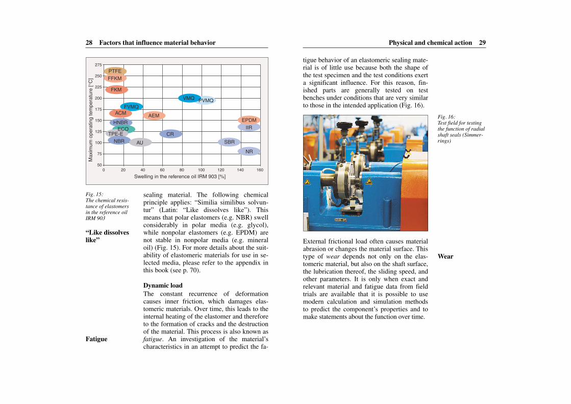
Fig. 15:The chemical resis-tance of elastomersin the reference oilIRM 903
Swelling in the reference oil IRM 903 [%]
NRSBR
IIREPDM
VMQ PVMQ
CR
AEM
AUNBR
PTFEFFKM
FKM
FVMQACM
HNBRECO
TPE-E
500 20 40 60 80 100 120 140 160
75
100
125
150
175
200
225
250
275
Max
imum
ope
ratin
g te
mpe
ratu
re [°
C]
Fig. 16:Test field for testingthe function of radialshaft seals (Simmer-rings)
External frictional load often causes materialabrasion or changes the material surface. Thistype of wear depends not only on the elas-tomeric material, but also on the shaft surface,the lubrication thereof, the sliding speed, andother parameters. It is only when exact andrelevant material and fatigue data from fieldtrials are available that it is possible to usemodern calculation and simulation methodsto predict the component’s properties and tomake statements about the function over time.
“Like dissolveslike”
Fatigue
Wear

Mixing technology 31
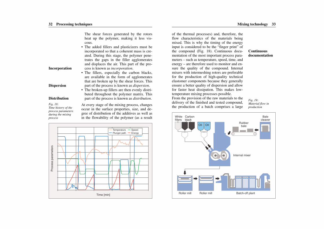
celerators). This so-called “spaghetti model”also highlights the demands that are made onthe mixing process. The art of mixing rubberlies in the breaking up of the various compo-nents and agglomerates and their even distrib-ution throughout the polymer matrix in orderto ensure the homogeneous quality of thecompound.As a rule, the various components cannot bemerged in a single operation. This is particu-larly true of compounds that use fine-particlecarbon blacks or natural rubber as their poly-mer base. The mixing process is generally di-vided into four stages:
• The cold raw polymer, which is fed into themixing chamber in bale form, must be bro-ken up in order to create sufficiently largesurfaces for the incorporation of the fillers.Two contradirectional rotors inside the mix -ing chamber are used for this purpose.
30
Processing techniquesPrerequisites for the production of compo-nents made of high-performance elastomermaterials include the reliability of the rawmaterial quality, exact raw material weightcontent, a controlled mixing process, and op-timized molding processes.
Mixing technologyElastomers are multi-component systems.The different raw materials with their varyingweight contents and consistencies must beprocessed in such a way as to create a homo-geneous compound. Rubber, for example, is delivered as a plastic polymer in bale orchip form and decreases in viscosity once itreaches processing temperature. Plasticizers,on the other hand, are generally delivered inoil form.
The mixing processThe objective of the mixing process is to dis-tribute all necessary raw materials evenly(distributive mixing) and to break up any ag-glomerates (dispersive mixing) in order toachieve an optimum connection between thefiller particles and the polymer. This is partic-ularly important because the interaction ofthe filler particles with the polymer matrixdetermines several properties, among themthe reinforcement of the elastomer. To illus-trate the different sizes of the compound in-gredients, figure 17 uses a strand of spaghettito illustrate the length and diameter of a rub-ber molecule and the dimensions of its com-ponents (carbon blacks, plasticizers, and ac-
Fig. 17:Using the so-called“spaghetti model” toillustrate the differ-ent sizes of the com-pound ingredients
Polymer tangle
Carbon black
aggregateZinc oxide
particle (segment)
Proportion model: spaghetti
Length Diameter Particle Length Diameter1±3 μm
50 nm190 nm320 nm
4 nm5 μm
0.8 nm
0.15 nm50 nm50 nm
180 nm2 nm5 μm
0.8 nm
Rubber molecule Polymer tangleCarbon black aggregate N330 Carbon black aggregate N990PlasticizerZinc oxideSulfur/accelerator
10±30 m0.5 m1.9 m3.2 m
40 mm50 m8 mm
15 mm0.5 m0.5 m1.8 m
20 mm50 m8 mm
Objective: creating a homogeneouscompound
Differently sizedcompound ingredients
Several operations
Mixing technology 33
of the thermal processes) and, therefore, theflow characteristics of the materials beingmixed. This is why the timing of the energyinput is considered to be the “finger print” ofthe compound (Fig. 18). Continuous docu-mentation of the most important process para-meters – such as temperature, speed, time, andenergy – are therefore used to monitor and en-sure the quality of the compound. Internalmixers with intermeshing rotors are preferablefor the production of high-quality technicalelastomer components because they generallyensure a better quality of dispersion and allowfor faster heat dissipation. This makes low-temperature mixing processes possible.From the provision of the raw materials to thedelivery of the finished and tested compound,the production of a batch comprises a large
32 Processing techniques
The shear forces generated by the rotorsheat up the polymer, making it less vis-cous.
• The added fillers and plasticizers must beincorporated so that a coherent mass is cre-ated. During this stage, the polymer pene-trates the gaps in the filler agglomeratesand displaces the air. This part of the pro-cess is known as incorporation.
• The fillers, especially the carbon blacks,are available in the form of agglomeratesthat are broken up by the shear forces. Thispart of the process is known as dispersion.
• The broken-up fillers are then evenly distri-buted throughout the polymer matrix. Thispart of the process is known as distribution.
At every stage of the mixing process, changesoccur in the surface properties, size, and de-gree of distribution of the additives as well asin the flowability of the polymer (as a result
Fig. 18:Time history of theprocess parametersduring the mixingprocess
Time [min]
Proc
ess p
aram
eter
s
TemperaturePlunger path
SpeedEnergy
Fig. 19:Material flow in production
Internal mixer
Roller mill Roller mill Batch-off plant
Rubber bale
Bale cleaver
White fillers
Carbon black
Oil Oil
Incorporation
Dispersion
Distribution
Continuous documentation
Mixing technology 35
break up filler agglomerates completely. Insuch cases, the compound moves through avery narrow roller gap (< 1 mm) with a si-multaneously high level of friction in an extraroller mill. This improves the quality of thecompound and is essential for compoundsthat require a high level of dispersion. This isthe case for safety components, pressureseals, and lip seals.
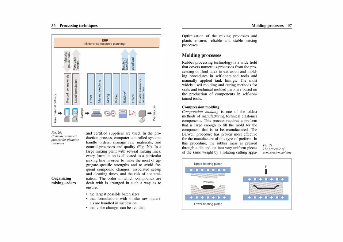
Quality aspects and process controlThe functional property and quality require-ments for parts delivered to companies in theautomotive and general industries have al-ready increased significantly in recent yearsand are set to increase even more in the fu-ture. Legal guidelines and the fact that cus-tomers are demanding higher quality meanthat continuous monitoring and documenta-tion of the raw material quality, compounds,and processes is a necessity. Systematic ad-vance quality planning ensures that all stagesof the process – from the design phase to thedevelopment and production of the com-pound that is ready for series production – arecarefully initiated and completed. During thedevelopment phase, for example, an FMEA(Failure Mode and Effects Analysis) is con-ducted in order to evaluate the compoundsand any risks involved in their production.In view of the fact that elastomer compoundsare “customized materials”, the manufactur-ers of technical elastomer products have tomanufacture and manage a large number ofdifferent compounds (up to 1,000). A corre-spondingly large number of raw materials isalso required for the production of the com-pounds. In order to ensure high-quality com-pounds, only raw materials from accepted
34 Processing techniques
number of different process stages. In order toensure the steady flow of material, a variety ofaggregates – from weighing equipment, balecleavers, internal mixer, and roller mill to thebatch-off plant – are needed (Fig. 19).
Using roller mills for homogenizationRoller mills generally have two rollers that arearranged one behind the other and run at dif-ferent speeds. The temperature at both rollerscan be controlled. The friction between theroller and the materials being mixed ensuresthat the flattened mixture (compound sheets)generally sticks to the slower front roller.The roller’s first task is to cool down the compound, the temperature of which can beas high as 150°C at the end of the mixingprocess in the internal mixer. The roller alsofurther homogenizes the compound. Themixing effect of the roller is based on severalfactors including the dispersion that occurs inthe roller gap as a result of the different rollerspeeds. The distribution of the compoundingredients is reinforced by cutting thecompound sheets and using auxiliary rollers,which are also known as stock blenders. Thesheeting-out of the compound is influenced by the width of the roller gap, the friction, and the temperature. If the formulation re -quires it, temperature-sensitive curing agentsand accelerators are added to the rolling mill after the cool-down phase. If the mixingline has two roller mills, there is more time for rolling during the internal mixer cycle. In order to ensure that processes can be repro-duced and repeated, the roller process is auto-matically monitored and documented.In exceptional cases, the compounds are sub-jected to very high shear forces in order to
Cooling and homogenization
Advance qualityplanning
High raw-material quality
Molding processes 37
Optimization of the mixing processes andplants ensures reliable and stable mixingprocesses.
Molding processesRubber processing technology is a wide fieldthat covers numerous processes from the pro-cessing of fluid latex to extrusion and mold-ing procedures in self-contained tools andmanually applied tank linings. The mostwidely used molding and curing methods forseals and technical molded parts are based onthe production of components in self-con-tained tools.
Compression moldingCompression molding is one of the oldestmethods of manufacturing technical elastomercomponents. This process requires a preformthat is large enough to fill the mold for thecomponent that is to be manufactured. TheBarwell procedure has proven most effectivefor the manufacture of this type of preform. Inthis procedure, the rubber mass is pressedthrough a die and cut into very uniform piecesof the same weight by a rotating cutting appa-
36 Processing techniques
and certified suppliers are used. In the pro-duction process, computer-controlled systemshandle orders, manage raw materials, andcontrol processes and quality (Fig. 20). In alarge mixing plant with several mixing lines,every formulation is allocated to a particularmixing line in order to make the most of ag-gregate-specific strengths and to avoid fre-quent compound changes, associated set-upand cleaning times, and the risk of contami-nation. The order in which compounds aredealt with is arranged in such a way as to ensure:
• the largest possible batch sizes• that formulations with similar raw materi-
als are handled in succession• that color changes can be avoided.
Fig. 20:Computer-assistedprocess for planningresources
Reco
rd ra
w m
ater
ials
Mat
erial
m
aste
r dat
a
Labe
l/form
ulatio
n
Quali
ty as
sura
nce
asse
ssm
ent
Feed
back
(w
eight
)
Batch
-off
(weig
hts)
good
/bad
Raw
mat
erial
deli
very
Stor
age
War
ehou
se
Chec
k
Batch
-off
Rollin
g
Mixi
ng
Man
ual w
eighin
g
Orde
r
ERP(Enterprise resource planning)
Fig. 21:The principle of compression molding
Upper heating platen
Lower heating platen
Preform
F
Organizing mixing orders

Molding processes 39
pressing the elastomer compound into themold cavity. Pressing the compound throughthe narrow channels ensures an intense ex-change of heat between the compound andthe wall of the tool. The flow speed also gen-erates high frictional heat. This must be takeninto account when developing the compoundformulation, because additional frictionalheat can lead to premature curing of the com-pound. The heating times for transfer mold-ing are much shorter than those required forcompression molding. Flash also forms in thetransfer molding procedure. However, it isgenerally thinner than the flash created bycompression molding. The transfer moldingprocedure allows molded parts to be manu-factured within tight tolerance limits, whichmeans that it is particularly good for the pro-duction of complex small parts.
Injection moldingInjection molding was used successfully inthe plastics industry for several years before
38 Processing techniques
ratus. The preform is subsequently inserted intothe component mold in the tool (mold cavity)and the press is closed. The heat generated bythe heated platen is transferred to the moldingcompound, thereby triggering the curingprocess (Fig. 21). Compression molding re-quires relatively long heating times. The reasonfor this is that the preform must be heated fromambient temperature to the curing temperature,which is somewhere between 150 and 180°C.In view of the fact that elastomers are poorconductors of heat, this process can take sev-eral minutes, especially in the case of thick-walled components. In order to avoid air en-trapments, the mold must be deventilated regu-larly by carefully opening the press severaltimes during the curing process. Any excessmaterial must also escape. The excess materialforms a rubber skin (flash) in the mold partingsurface of the two tool halves. This flash mustbe removed from the molded part in a separatefinishing process after vulcanization.
Transfer moldingThe transfer molding procedure is a refinedversion of compression molding and can es-sentially be performed using existing com-pression molding presses. Here, the upperhalf of the tool contains a cavity known as a“pot” into which the uncured compound is inserted in the form of a simple preform (Fig. 22). The pot in the upper half of the toolis connected to the mold cavity below by a se -ries of narrow channels. The most importantdifference between compression and transfermolding is that in transfer molding, the moldcavity is already closed when the pressprocess begins. When the press is closed, thetool pushes against an integral piston, thereby
Fig. 22:The principle oftransfer molding
Upper heating platen
Lower heating platen
Preform
F
Long heatingtimes
Molding usingchannels
Shorter heatingtimes

Molding processes 41
curing time in the injection molding processis shorter than that in all of the otherprocesses mentioned here. However, as a re-sult of the comparatively high investmentcosts associated with this process, injectionmolding is only suitable for larger productionseries.
Other technologiesThe problem of deflashing – or the avoidanceof the formation of flashes in the first place –has led to the development of new processesand tools. The surface of the tool can, for ex-ample, be modified in such a way that air, butnot elastomer, can escape from the mold cav-ity. This method is known as ready molding,or the flash-less process, and is particularlysuitable for the manufacture of high-precisionmolded parts.The combination of various moldingprocesses has also resulted in the develop-ment of other processes. As the name sug-gests, the injection ready molding process, forexample, combines the features of injectionand ready molding. Injection compressionmolding is used to manufacture small, flatmolded parts, especially O-rings. Thisprocess is based on the fact that a very tinygap remains open when the tool is closed.The required pre-plasticized compound isthen injected into this gap and the press isclosed. Flat, high-precision molded parts thatare largely flash-free can be manufactured us-ing this process.For the cold runner injection moldingprocess, the injection channels are kept ther-mally separate from the tool. Thanks to theoptimized design of the channel system andthe fact that the temperature is kept at the
40 Processing techniques
being introduced into the rubber industry. Thestructure of the tool used for injection mold-ing is similar to that used for transfer moldingwith the exception that the individual moldcavities in the latter are connected to the gate(injection point) by means of channels. Themolding process starts when the tool isclosed. The pre-plasticized compound is theninjected at high pressure through the injectionnozzle into the distribution channels and onto the mold cavities (Fig. 23). The preferredtype of injection molding used in the rubberindustry features screw pre-plasticization andplunger injection. Here, the plasticization andinjection procedures are kept separate,thereby ensuring that the full potential ofevery part of the plant can be exploited. As aresult of pre-plasticization, the compound isalmost at curing temperature when it entersthe mold cavity. This means that the actual
Fig. 23:The principle of injection molding
Screwpre-plasticization
Distributionchannels
Injectionplunger
Separate units
For larger production series
Injection readymolding
Injection compressionmolding
Cold runner in-jection molding

Optimizing elastomer processing procedures 43
processes such as the conventional injectionmolding or the injection ready moldingprocess, and allows for a high level of au-tomation.
Optimizing elastomer processingproceduresRegardless of the curing process in question,it is vitally important to know the rheologi-cal properties of the compounds in order tobe able to adjust process parameters to suitthe material. Rheology concerns itself withthe flow characteristics (viscosity) and shearbehavior of materials. When it comes to op-timizing production processes and savingcosts in the rubber-processing industry, rhe-ology and process simulation are inextrica-bly linked. A knowledge of cross-linkingreactions and their speeds helps the persondeveloping the compound to determine thereaction kinetics and the chemical engineerto determine the ideal heating time. It alsofacilitates quality assurance in production.Rheological data is used for flow or injec-tion simulations in injection molding in or-der to determine the dependency of the shearrate on viscosity and to use the results tocalculate the elastic proportion of the elas-tomer stress. The simulation of injectionprocesses is, therefore, an important aidwhen it comes to manufacturing defect-freecomponents. For example, the flow frontprogression and the position of flow lines orthe pressure required for selecting a suitableinjection molding unit can all be calculatedmathematically. This allows potential sourcesof error, such as entrapped air, to be iden -tified and eliminated at an early stage.
42 Processing techniques
right level, there is no loss of material as a re-sult of previously cured sprues (Fig. 24). Thissaves huge amounts of material, which is par-ticularly valuable when it comes to high-quality compounds. By cleverly designing thechannels, larger molded parts with smallcross-sections can be manufactured. Com-pounds with very high free-flowing charac-teristics are required for this process. Onepositive side effect of these good free-flowingcharacteristics is the fact that they allow foran increase in injection speed. Not only doesthis save time, it also means that channels nolonger have to be demolded and removedfrom the molded part. Cold runner injectionmolding can be combined with all molding
Fig. 24:The principle of cold runner injectionmolding
Cooling
InsulationUpper heating platen
Lower heating platen
Screwpre-plasticization
Injection plunger
Time and material savings
Flow or injec-tion simulations

Optimizing elastomer processing procedures 45
Simulation of the compression moldingprocess poses a particular challenge. In con-trast to injection molding simulation, wherethe time-varying flow front within a rigid area (fixed walls of the mold cavity) needs tobe calculated, not only does the flow front –and consequently the parameters – change inthe case of compression molding, but the twohalves of the tool also move towards eachother.The advantage of all process simulations isthat the parameters can be reliably altered,optimized, and checked on computer withindays or hours. The findings can be channeledinto the product and process design at anearly stage of development. Simulationmakes physical contexts and processes moretransparent, thereby allowing the user to im-prove his/her understanding of the product orprocess – something that is not the case withexclusively experimental examinations. Thismeans that optimization processes can beused in a targeted manner in places where thegreatest potential is visible. It also means thatmaximum development results can beachieved at minimum expense and effort.
44 Processing techniques
By supplementing universal flow simulationprograms with optimized material modelsthat describe cure kinetics, both the scorchindex (flow period, i.e. the time that elapsesbefore the elastomer starts to cross-link) andthe cross-link density during the injectionmolding of elastomer parts can be calcu-lated.An elastomer particle experiences fluctuatingshear and elongation deformation betweenthe time it is filled into the cylinder of the in-jection molding machine and the time itreaches its final position in the tool. Thestrong speed gradients at the side walls of theinjection channel and the narrow temperatureboundary layers must be taken into accountfor the simulation. Both special softwarepackages and considerable computing powerare needed to describe the complex, three-dimensional flow processes (Fig. 25).
Fig. 25:Injection simulationof a conical springillustrates complexflow processes.
Considerablecomputingpower
Early optimization
Calculating thescorch index
Testing during the production process 47
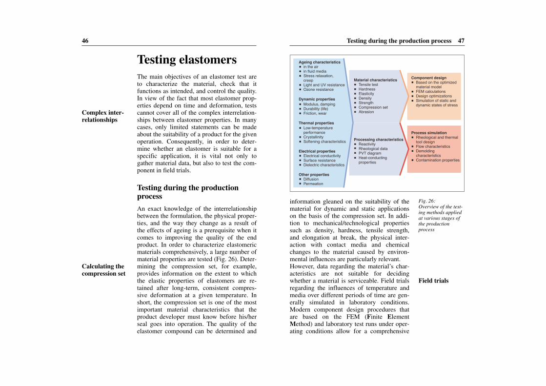
information gleaned on the suitability of thematerial for dynamic and static applicationson the basis of the compression set. In addi-tion to mechanical/technological propertiessuch as density, hardness, tensile strength,and elongation at break, the physical inter -action with contact media and chemicalchanges to the material caused by environ-mental influences are particularly relevant.However, data regarding the material’s char-acteristics are not suitable for decidingwhether a material is serviceable. Field trialsregarding the influences of temperature andmedia over different periods of time are gen-erally simulated in laboratory conditions.Modern component design procedures thatare based on the FEM (Finite ElementMethod) and laboratory test runs under oper-ating conditions allow for a comprehensive
46
Testing elastomersThe main objectives of an elastomer test areto characterize the material, check that itfunctions as intended, and control the quality.In view of the fact that most elastomer prop-erties depend on time and deformation, testscannot cover all of the complex interrelation-ships between elastomer properties. In manycases, only limited statements can be madeabout the suitability of a product for the givenoperation. Consequently, in order to deter-mine whether an elastomer is suitable for aspecific application, it is vital not only togather material data, but also to test the com-ponent in field trials.
Testing during the productionprocessAn exact knowledge of the interrelationshipbetween the formulation, the physical proper-ties, and the way they change as a result ofthe effects of ageing is a prerequisite when itcomes to improving the quality of the endproduct. In order to characterize elastomericmaterials comprehensively, a large number ofmaterial properties are tested (Fig. 26). Deter-mining the compression set, for example, provides information on the extent to whichthe elastic properties of elastomers are re-tained after long-term, consistent compres-sive deformation at a given temperature. Inshort, the compression set is one of the mostimportant material characteristics that theproduct developer must know before his/herseal goes into operation. The quality of theelastomer compound can be determined and
Fig. 26:Overview of the test-ing methods appliedat various stages ofthe productionprocess
Tensile testHardnessElasticityDensityStrengthCompression setAbrasion
Material characteristics Based on the optimized material modelFEM calculationsDesign optimizationsSimulation of static and dynamic states of stress
Component design
Rheological and thermal tool designFlow characteristicsDemolding characteristicsContamination properties
Process simulation
ReactivityRheological dataPVT diagramHeat-conductingproperties
Processing characteristics
in the airin fluid mediaStress relaxation, creepLight and UV resistanceOzone resistance
Ageing characteristics
Modulus, dampingDurability (life)Friction, wear
Dynamic properties
Low-temperature performanceCrystallinitySoftening characteristics
Thermal properties
Electrical conductivitySurface resistanceDielectric characteristics
Electrical properties
DiffusionPermeation
Other properties
Complex inter-relationships
Calculating thecompression set
Field trials

Component simulation using FEM 49
tests enhance numerical material models,thereby providing a comprehensive idea ofthe durability and, consequently, the workinglife of the elastomer seal.
Component simulation using FEMThe finite element method is used in indus-trial product development as a calculationprocedure for solving complex problemsrelating to statics, strength, dynamics, andthermodynamics. In order to ensure the bestpossible design, the shortest possible devel-opment times, and top product quality whendeveloping a technical elastomeric compo-nent, it is necessary to apply optimized meth-ods of calculating the non-linear behavior andthus to illustrate the behavior of the materialin the most accurate way possible. Non-linear FEM calculation models are indis-pensable when it comes to describing impor-tant phenomena such as the operating perfor-mance of elastomeric components, the processsimulation in forming technology, or the cal-
48 Testing elastomers
assessment of the function of components.Ideally, unambiguous statements about theserviceability of a material are based on theresults of field trials featuring componentprototypes.
Estimating the working lifeMechanical, thermal, and dynamic character-istic values are the basis for the developmentof material models, where not only the influ-ences of the compound and the environment,but also the behavior of the material underdynamic load are taken into consideration.Unlike other materials such as metals and ce-ramics, there is no linear relationship betweenstress and strain in elastomers. In addition tothis non-linear behavior, the stiffness of thematerial as a function of the deformationspeed must be taken into account. Optimizedmaterial models – so-called hyperelastic ma-terial models – demonstrate good correlationbetween the experimental data and remainvalid (Fig. 27) even in the event of consider-able material deformation (>150%).Evaluation of the ageing stability of elas-tomers is a particularly important criterionwhen it comes to assessing the durability ofseals. The tests generally take the form oftensile tests on aged samples. In this regard, itis important to note that short-term and sin-gle-point determinations can always lead tomisinterpretations. Observing ageing phe-nomena at different temperature and time in-tervals, on the other hand, can provide signif-icantly more meaningful results and allow thelong-term behavior of the elastomer to be es-timated. Additional information that is ob-tained from component analyses and ageing
Strain [%]
Stre
ss [M
Pa]
-1-50 0 50 100 200150
0
1
2
3
Experimental data Neo-HookeMooney-RivlinOptimized material model
Fig. 27:A comparison of different materialmodels and experi-mental data regardingstress-strain behavior
Hyperelasticmaterial models
Evaluating ageing stability
Non-linear FEM model
Component simulation using FEM 51
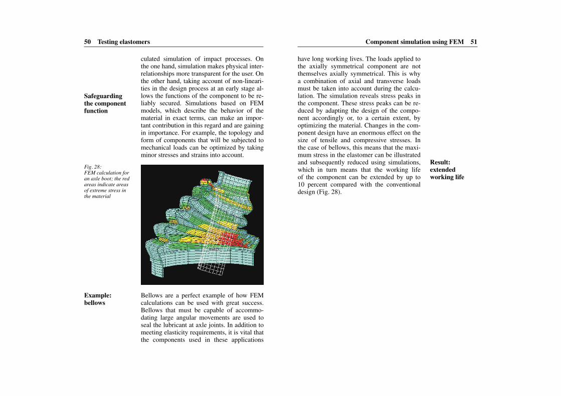
have long working lives. The loads applied tothe axially symmetrical component are notthemselves axially symmetrical. This is whya combination of axial and transverse loadsmust be taken into account during the calcu-lation. The simulation reveals stress peaks inthe component. These stress peaks can be re-duced by adapting the design of the compo-nent accordingly or, to a certain extent, byoptimizing the material. Changes in the com-ponent design have an enormous effect on thesize of tensile and compressive stresses. Inthe case of bellows, this means that the maxi-mum stress in the elastomer can be illustratedand subsequently reduced using simulations,which in turn means that the working life of the component can be extended by up to10 percent compared with the conventionaldesign (Fig. 28).
50 Testing elastomers
culated simulation of impact processes. Onthe one hand, simulation makes physical inter-relationships more transparent for the user. Onthe other hand, taking account of non-lineari-ties in the design process at an early stage al-lows the functions of the component to be re-liably secured. Simulations based on FEMmodels, which describe the behavior of thematerial in exact terms, can make an impor-tant contribution in this regard and are gainingin importance. For example, the topology andform of components that will be subjected tomechanical loads can be optimized by takingminor stresses and strains into account.
Fig. 28:FEM calculation foran axle boot; the redareas indicate areasof extreme stress inthe material
Bellows are a perfect example of how FEMcalculations can be used with great success.Bellows that must be capable of accommo-dating large angular movements are used toseal the lubricant at axle joints. In addition tomeeting elasticity requirements, it is vital thatthe components used in these applications
Safeguardingthe componentfunction
Example: bellows
Result: extended working life
High-tech products made of technical elastomers 53
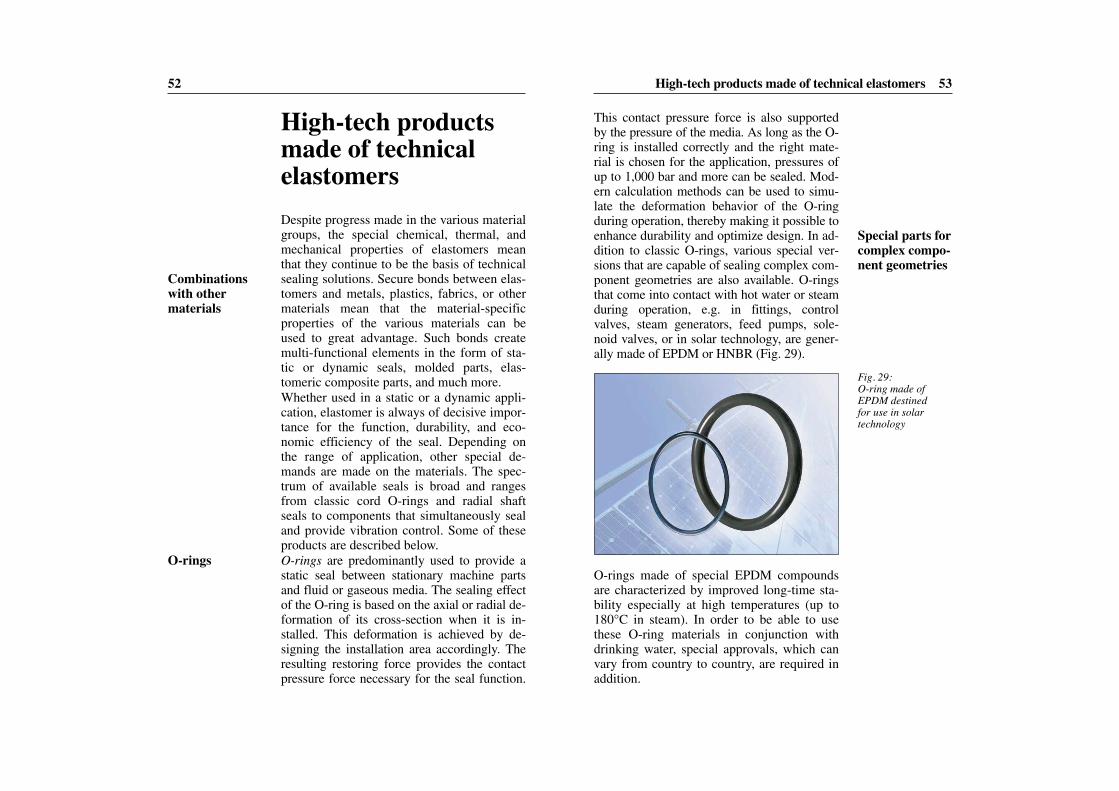
This contact pressure force is also supportedby the pressure of the media. As long as the O-ring is installed correctly and the right mate -rial is chosen for the application, pressures ofup to 1,000 bar and more can be sealed. Mod-ern calculation methods can be used to simu-late the deformation behavior of the O-ringduring operation, thereby making it possible toenhance durability and optimize design. In ad-dition to classic O-rings, various special ver-sions that are capable of sealing complex com-ponent geometries are also available. O-ringsthat come into contact with hot water or steamduring operation, e.g. in fittings, controlvalves, steam generators, feed pumps, sole-noid valves, or in solar technology, are gener-ally made of EPDM or HNBR (Fig. 29).
52
High-tech productsmade of technicalelastomersDespite progress made in the various materialgroups, the special chemical, thermal, andmechanical properties of elastomers meanthat they continue to be the basis of technicalsealing solutions. Secure bonds between elas-tomers and metals, plastics, fabrics, or othermaterials mean that the material-specificproperties of the various materials can beused to great advantage. Such bonds createmulti-functional elements in the form of sta-tic or dynamic seals, molded parts, elas-tomeric composite parts, and much more.Whether used in a static or a dynamic appli-cation, elastomer is always of decisive impor-tance for the function, durability, and eco-nomic efficiency of the seal. Depending onthe range of application, other special de-mands are made on the materials. The spec-trum of available seals is broad and rangesfrom classic cord O-rings and radial shaftseals to components that simultaneously sealand provide vibration control. Some of theseproducts are described below.O-rings are predominantly used to provide astatic seal between stationary machine partsand fluid or gaseous media. The sealing effectof the O-ring is based on the axial or radial de-formation of its cross-section when it is in-stalled. This deformation is achieved by de-signing the installation area accordingly. Theresulting restoring force provides the contactpressure force necessary for the seal function.
Fig. 29:O-ring made ofEPDM destined for use in solar technology
Combinationswith other materials
O-rings
Special parts forcomplex compo-nent geometries
O-rings made of special EPDM compoundsare characterized by improved long-time sta-bility especially at high temperatures (up to180°C in steam). In order to be able to usethese O-ring materials in conjunction withdrinking water, special approvals, which canvary from country to country, are required inaddition.
High-tech products made of technical elastomers 55
industry must also be highly resistant to steamand aggressive detergents. In other words theymust be suitable for use in CIP (cleaning inplace) and SIP (sterilization in place) proce-dures. By virtue of the fact that they come intocontact with foods, only harmless compoundingredients may be used in the elastomericcompounds for these applications. Moreover,these compound ingredients must complywith relevant legal guidelines (e.g. the recom-mendations of the BfR and FDA CFR 21 § 177.2600). New developments in this areainclude high-performance materials that arebased on EPDM, HNBR, FKM, and in specialcases, on FFKM. HNBR compounds, forexample, combine very good mechanicalstrength values with good frictional character-istics. In view of the fact that HNBR is highlyresistant to fats, waxes, and oils, these com-pounds are widely used in plants where thesemedia have to be blocked or controlled. Theoperating temperature range for HNBR butter-fly valve seals is –20°C to +140°C.Diaphragms are always used in applicationswhere components must be linked in a flexi-ble way, spaces between components sepa-rated, and at the same time a tight separatingwall ensured between them. In view of thewide range of possible diaphragm functions(transporting, adjusting, controlling, sealing,separating, storing), diaphragms can be usedin applications in the fields of mechanical engineering, automotive technology, spacetravel, and medical technology. In the major-ity of cases, customized solutions are neededto meet varying requirements with regard tomechanical, thermal, and chemical loads. Di-aphragms are used, for example, in pumpsthat transport fuel or lubricating media, or as
54 High-tech products made of technical elastomers
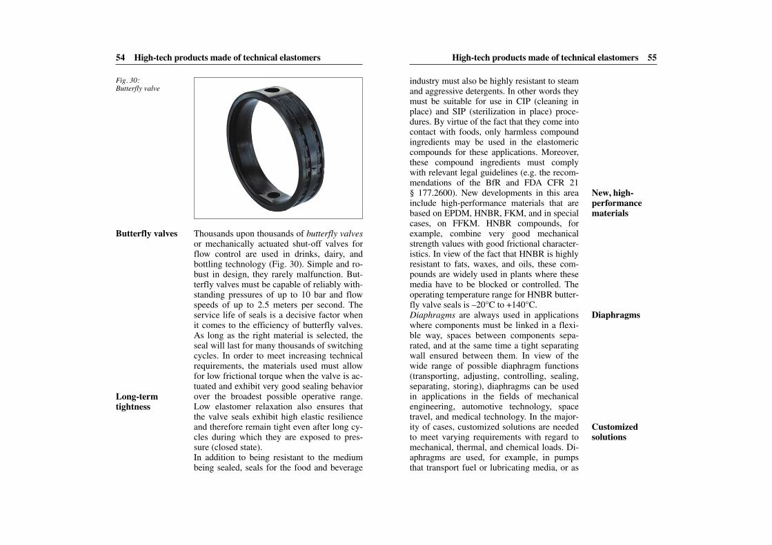
Thousands upon thousands of butterfly valvesor mechanically actuated shut-off valves forflow control are used in drinks, dairy, andbottling technology (Fig. 30). Simple and ro-bust in design, they rarely malfunction. But-terfly valves must be capable of reliably with-standing pressures of up to 10 bar and flowspeeds of up to 2.5 meters per second. Theservice life of seals is a decisive factor whenit comes to the efficiency of butterfly valves.As long as the right material is selected, theseal will last for many thousands of switchingcycles. In order to meet increasing technicalrequirements, the materials used must allowfor low frictional torque when the valve is ac-tuated and exhibit very good sealing behaviorover the broadest possible operative range.Low elastomer relaxation also ensures thatthe valve seals exhibit high elastic resilienceand therefore remain tight even after long cy-cles during which they are exposed to pres-sure (closed state).In addition to being resistant to the mediumbeing sealed, seals for the food and beverage
Fig. 30:Butterfly valve
Long-term tightness
New, high-performance materials
Diaphragms
Customized solutions
Butterfly valves
High-tech products made of technical elastomers 57
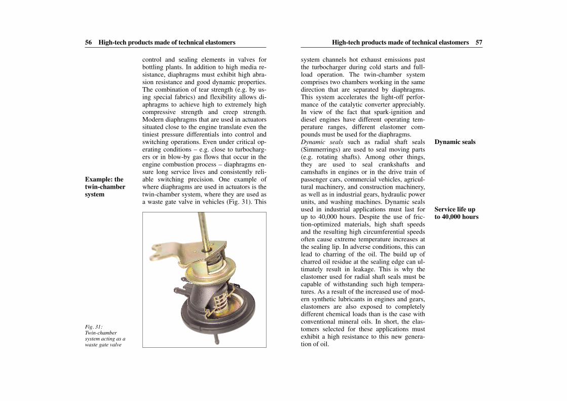
system channels hot exhaust emissions pastthe turbocharger during cold starts and full-load operation. The twin-chamber systemcomprises two chambers working in the samedirection that are separated by diaphragms.This system accelerates the light-off perfor-mance of the catalytic converter appreciably.In view of the fact that spark-ignition anddiesel engines have different operating tem-perature ranges, different elastomer com-pounds must be used for the diaphragms.Dynamic seals such as radial shaft seals(Simmerrings) are used to seal moving parts(e.g. rotating shafts). Among other things,they are used to seal crankshafts andcamshafts in engines or in the drive train ofpassenger cars, commercial vehicles, agricul-tural machinery, and construction machinery,as well as in industrial gears, hydraulic powerunits, and washing machines. Dynamic sealsused in industrial applications must last forup to 40,000 hours. Despite the use of fric-tion-optimized materials, high shaft speedsand the resulting high circumferential speedsoften cause extreme temperature increases atthe sealing lip. In adverse conditions, this canlead to charring of the oil. The build up ofcharred oil residue at the sealing edge can ul-timately result in leakage. This is why theelastomer used for radial shaft seals must becapable of withstanding such high tempera-tures. As a result of the increased use of mod-ern synthetic lubricants in engines and gears,elastomers are also exposed to completelydifferent chemical loads than is the case withconventional mineral oils. In short, the elas-tomers selected for these applications mustexhibit a high resistance to this new genera-tion of oil.
56 High-tech products made of technical elastomers
control and sealing elements in valves forbottling plants. In addition to high media re-sistance, diaphragms must exhibit high abra-sion resistance and good dynamic properties.The combination of tear strength (e.g. by us-ing special fabrics) and flexibility allows di-aphragms to achieve high to extremely highcompressive strength and creep strength.Modern diaphragms that are used in actuatorssituated close to the engine translate even thetiniest pressure differentials into control andswitching operations. Even under critical op-erating conditions – e.g. close to turbocharg-ers or in blow-by gas flows that occur in theengine combustion process – diaphragms en-sure long service lives and consistently reli-able switching precision. One example ofwhere diaphragms are used in actuators is thetwin-chamber system, where they are used asa waste gate valve in vehicles (Fig. 31). This
Fig. 31:Twin-chamber system acting as awaste gate valve
Example: thetwin-chambersystem
Dynamic seals
Service life upto 40,000 hours

High-tech products made of technical elastomers 59
form a sub-assembly. Without the need forboreholes, seals, and ducts, this multi-func-tional sealing system allows electrical signalsto be sent into or out of an area filled with amedium and/or subject to pressure. Given thesignificant design freedom allowed by thissystem, it can be used in a wide range of ap-plications in the automotive and consumergoods industries as well as for medical andtelecommunications technology. The minia-turization of this sealing system and the factthat the flexible printed circuit board can befolded mean that this is a space-saving com-ponent that can be installed in even the small-est installation areas.Bellows and dust boots are both used in theautomotive, construction machinery, and foodindustries as well as for electrotechnical ap-plications and medical technology. In cars,they are used to protect axles, transmissionsystems, shock absorbers, and steering sys-tems. Drive shafts, propshafts, ball joints intie rods, and stabilizers are all protectedagainst the infiltration of dirt and moisture byspecial elastomeric bellows. Elastomeric bel-lows used in drive shafts also prevent the loss
58 High-tech products made of technical elastomers
In order to identify functional difficulties ingood time, radial shaft seals can also be man-ufactured with additional functions such as aleakage sensor.If the seal’s sealing function diminishes oncethe product has reached a certain age, a leak-age collector absorbs any fluid that escapes.An integral sensor identifies the leakage andsends a signal that indicates when the systemwill need to be serviced and the seal replaced(Fig. 32). This helps avoid unscheduled ma-chine downtime.New ground is also being broken in the fieldsof control and sensor technology in order tomeet the requirements of low leakage rates(in the ppm range), reliability, and cost opti-mization. The combination of flexible printedcircuit board technology and elastomers inthe form of multi-functional sealing systemsforms the basis of products that are capableof simultaneously sealing and transferring in-terference-free electric signals without theneed for conventional cables (Fig. 33). Thissystem consists of a static seal with integratedsensor, a plug, and a flexible printed circuitboard that connects all the components to
Fig. 32:Simmerring® withleakage sensor
Fig. 33:Sealing solutionswith integral sensor,plug, and flexibleprinted circuit boardcan be manufacturedfor almost any kindof installation area.
Multi-functionalsealing systems
Space-saving solutions
Bellows anddust boots …
… protect sensi-tive components
Integral leakagesensor
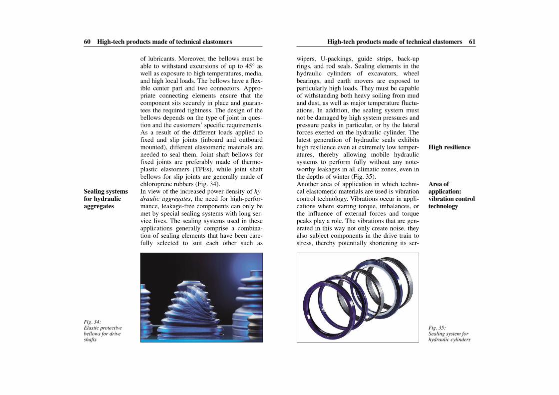
High-tech products made of technical elastomers 61
wipers, U-packings, guide strips, back-uprings, and rod seals. Sealing elements in thehydraulic cylinders of excavators, wheel bearings, and earth movers are exposed toparticularly high loads. They must be capableof withstanding both heavy soiling from mudand dust, as well as major temperature fluctu-ations. In addition, the sealing system mustnot be damaged by high system pressures andpressure peaks in particular, or by the lateralforces exerted on the hydraulic cylinder. Thelatest generation of hydraulic seals exhibitshigh resilience even at extremely low temper-atures, thereby allowing mobile hydraulicsystems to perform fully without any note-worthy leakages in all climatic zones, even inthe depths of winter (Fig. 35).Another area of application in which techni-cal elastomeric materials are used is vibrationcontrol technology. Vibrations occur in appli-cations where starting torque, imbalances, orthe influence of external forces and torquepeaks play a role. The vibrations that are gen-erated in this way not only create noise, theyalso subject components in the drive train tostress, thereby potentially shortening its ser-
60 High-tech products made of technical elastomers
of lubricants. Moreover, the bellows must beable to withstand excursions of up to 45° aswell as exposure to high temperatures, media,and high local loads. The bellows have a flex-ible center part and two connectors. Appro-priate connecting elements ensure that thecomponent sits securely in place and guaran-tees the required tightness. The design of thebellows depends on the type of joint in ques-tion and the customers’ specific requirements.As a result of the different loads applied tofixed and slip joints (inboard and outboardmounted), different elastomeric materials areneeded to seal them. Joint shaft bellows forfixed joints are preferably made of thermo-plastic elastomers (TPEs), while joint shaftbellows for slip joints are generally made ofchloroprene rubbers (Fig. 34).In view of the increased power density of hy-draulic aggregates, the need for high-perfor-mance, leakage-free components can only bemet by special sealing systems with long ser-vice lives. The sealing systems used in theseapplications generally comprise a combina-tion of sealing elements that have been care-fully selected to suit each other such as
Fig. 34:Elastic protectivebellows for driveshafts
Fig. 35:Sealing system forhydraulic cylinders
Sealing systemsfor hydraulic aggregates
High resilience
Area of application: vibration control technology
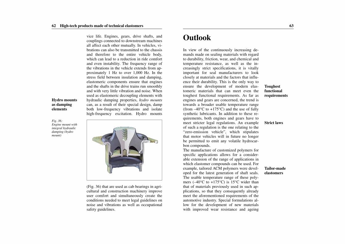
63
OutlookIn view of the continuously increasing de-mands made on sealing materials with regardto durability, friction, wear, and chemical andtemperature resistance, as well as the in-creasingly strict specifications, it is vitallyimportant for seal manufacturers to lookclosely at materials and the factors that influ-ence their durability. This is the only way toensure the development of modern elas-tomeric materials that can meet even thetoughest functional requirements. As far asengines and gears are concerned, the trend istowards a broader usable temperature range(from –40°C to +175°C) and the use of fullysynthetic lubricants. In addition to these re-quirements, both engines and gears have tomeet stricter legal regulations. An exampleof such a regulation is the one relating to the“zero-emission vehicle”, which stipulatesthat motor vehicles will in future no longerbe permitted to emit any volatile hydrocar-bon compounds.The manufacture of customized polymers forspecific applications allows for a consider-able extension of the range of applications inwhich elastomer compounds can be used. Forexample, tailored ACM polymers were devel-oped for the latest generation of shaft seals.The usable temperature range of these poly-mers (–40°C to +175°C) is 15°C wider thanthat of materials previously used in such ap-plications, so that they consequently alreadymeet the aforementioned requirements of theautomotive industry. Special formulations al-low for the development of new materialswith improved wear resistance and ageing
62 High-tech products made of technical elastomers
vice life. Engines, gears, drive shafts, andcouplings connected to downstream machinesall affect each other mutually. In vehicles, vi-brations can also be transmitted to the chassisand therefore to the entire vehicle body,which can lead to a reduction in ride comfortand even instability. The frequency range ofthe vibrations in the vehicle extends from ap-proximately 1 Hz to over 1,000 Hz. In thestress field between insulation and damping,elastomeric components ensure that enginesand the shafts in the drive trains run smoothlyand with very little vibration and noise. Whenused as elastomeric decoupling elements withhydraulic damping properties, hydro mountscan, as a result of their special design, dampboth low-frequency vibrations and isolatehigh-frequency excitation. Hydro mounts
Fig. 36:Engine mount withintegral hydraulicdamping (hydromount)
(Fig. 36) that are used as cab bearings in agri-cultural and construction machinery improveuser comfort and simultaneously create theconditions needed to meet legal guidelines onnoise and vibrations as well as occupationalsafety guidelines.
Hydro mountsas damping elements
Toughest functional requirements
Strict laws
Tailor-madeelastomers
Outlook 65
about a significant reduction in energy con-sumption and the emission of carbon dioxidesin the field of transport and energy supply.However, the requirements for seals used infuel cell systems are completely different tothose for seals used in conventional combus-tion engines. Here, for example, gas perme-ation or very tough requirements regardingchemical purity play a very important role.Accordingly, the seals used in these systemsmust be impermeable to gas and exhibit highchemical resistance to the reaction productsgenerated in the fuel cell.The trend towards multi-functional sealingmodules combined with modern processingtechnology makes it possible to produce com-ponents that are both delicate and complex.An in-depth understanding and knowledge ofmaterials and the use of ultra-modern calcula-tion processes such as FEM, and high-perfor-mance drawing and construction programssuch as CAD will further accelerate the de-velopment of innovative elastomeric materi-als that meet the high requirements of quality,performance, and durability.
64 Outlook
stability, which enhance the durability of thecomponent.As a result of the growing importance of electronics in general and the increased use ofelectric drives, new sealing concepts intowhich additional functions are integrated arebeing developed. These new designs renderindividual components superfluous, therebyreducing the required installation space, cut-ting weight, and ultimately simplifying instal-lation for the user. For example, radial shaftseals with elastomeric encoder elements andactive sensors for measuring vehicle speeds,especially in ABS systems, are already avail-able. These seals feature a magnetizable elas-tomer layer with encoded sectors (see coverphoto) that is attached either axially or radi-ally to the outer side of the seal. A field sen-sor registers the varying intensities along themagnetic field and uses this data to provide asignal that gives information about the speed.In future, more consideration must be givento another aspect, namely electromagneticshielding. The increase in the number of elec-tric systems used in vehicles causes electro-magnetic interference, which in turn cancause components to malfunction. The devel-opment of elastomers with increased electri-cal conductivity prevents electrostatic chargeand interference caused by the mutual inter-action of electrical components. Seals madeof such electrically conductive elastomericmaterials will in future be used in the field ofsensor technology or electronic communica-tions technology.The development of hydrogen and fuel celltechnology is considered to be an importantpillar of future development. It is ferventlyhoped that these technologies will bring
Integration of additional functions
Electrically conductiveelastomers
Fuel cell
Key to success:materials expertise
Glossary/Bibliography 67
Rheology The branch of science that deals with the deformation and flowbehavior of materials.
Rubber (Mayan language: cao = tree and ochu = tear) A collective term fornon-cross-linked, elastic polymers.
Scorch index The flow period, i.e. the time that elapses prior to cross-link-ing of the elastomer.
Simmerring® Radial shaft seal, a trademark registered by Freudenberg.
Stress relaxation The decrease in stress over time under constant deforma-tion and temperature.
Thermoplastics Plastics that can be plastically deformed under the influenceof heat. Thermoplastics generally comprise polymers with linear or slightlybranched chain molecules.
Thermosets Plastics that can no longer be molded once they have beencured.
Torque The product of an applied force and the distance between the pointof application and the fulcrum.
Viscoelasticity The time-, temperature-, and speed-dependent elasticity ofpolymers, molten materials, or solids (plastics).
66
GlossaryAgglomerates Condensed particles comprising a multitude of individualparticles and measuring between approximately 50 and 100 nanometers (nm)in diameter.
Amorphous The adjective describes materials in which the atoms do notexhibit an arranged structure, but instead adhere to an irregular pattern. Theadjective ‘crystalline’, on the other hand, is used to describe materials with aregular structure.
Batch-off plant Situated downstream of the mixing process, this plant isused to cool the sheeted-out elastomer compound.
Brownian motion The phenomenon that describes the thermally drivenproper motion of molecules.
Creep The temperature- and time-dependent deformation of materials ex-posed to constant, long-term mechanical load.
Cross-linking Chemical reaction that is initiated by heat and/or pressure inwhich the polymer chains are linked to one another to obtain elastic properties.
Curing Process whereby rubber is transformed into a rubbery-elastic state asa result of a change in its chemical structure; also known as vulcanization.
Diffusion The equalization of differences in concentration between gaseousor dissolved substances in which particles move dependant on temperaturefrom the area of higher concentration to the area of lower concentration.
Elastic modulus The tensile modulus of elasticity is an expression of the re-lationship between tensile stress and elongation. It describes the stiffness of the elastomer.
Elastomers Polymeric networks that are capable of absorbing large defor-mations in a reversible manner; cured rubber.
Entropy A thermodynamic quantity that describes the molecular mobility(disorder) of a system.
Flash A protruding edge of elastomer that forms during the molding proce-dure.
FEM Abbreviation of Finite Element Method; a numerical mathematicalmethod.
FMEA Abbreviation of Failure Mode and Effects Analysis. The FMEA is ananalytical method of identifying potential weak points.
Glass transition temperature The temperature at which polymers changefrom being flexible (the rubbery-elastic state) to being brittle (the energy-elas-tic state). This temperature varies from one polymer to another.
Polymer A macromolecule made of similar units (monomers). A polymercan be made of linear or branched molecules.
BibliographyFreudenberg Forschungsdienste KG, Elastomere Werkstoffe (2001).
Hirsch, V., Schneider, E., and Weiß, R., “Numerische Berechnungen für Dich-tungen und Bauteile”, MTZ, Vol. 65, 10/2004, p. 812.
Kaczmarek, M., Rieg, F., Taschenbuch der Maschinenelemente, Hanser undFachbuchverlag (Leipzig, 2006).
Krompf, W., “Membrantechnik für motornahe Aktuatoren”, MTZ, Vol. 66,4/2005, p. 288.
Mars, W.V., “Factors that affect the fatigue life of rubber: a literature survey”,Rubber Chemistry and Technology, Vol. 77, Issue 3, 2004, p. 391.
Priebe, N., “Kontinuierliches Mischen von Kautschukmischungen”, KGK –Kautschuk, Gummi, Kunststoffe, Vol. 58, 03/2005, p. 102–108.
Röthemeyer, F. and Sommer, F., Kautschuktechnologie (Hanser Verlag, 2001).
von Arndt, E. and Bußmann, M., “Gleiche Mischungsqualität von verschiede-nen Produktionsstandorten – Qualitätssystem eines multinationalen Gum-miverarbeiters”, VDI-Jahrestagung Mischen Extrudieren Spritzgießen (2000).
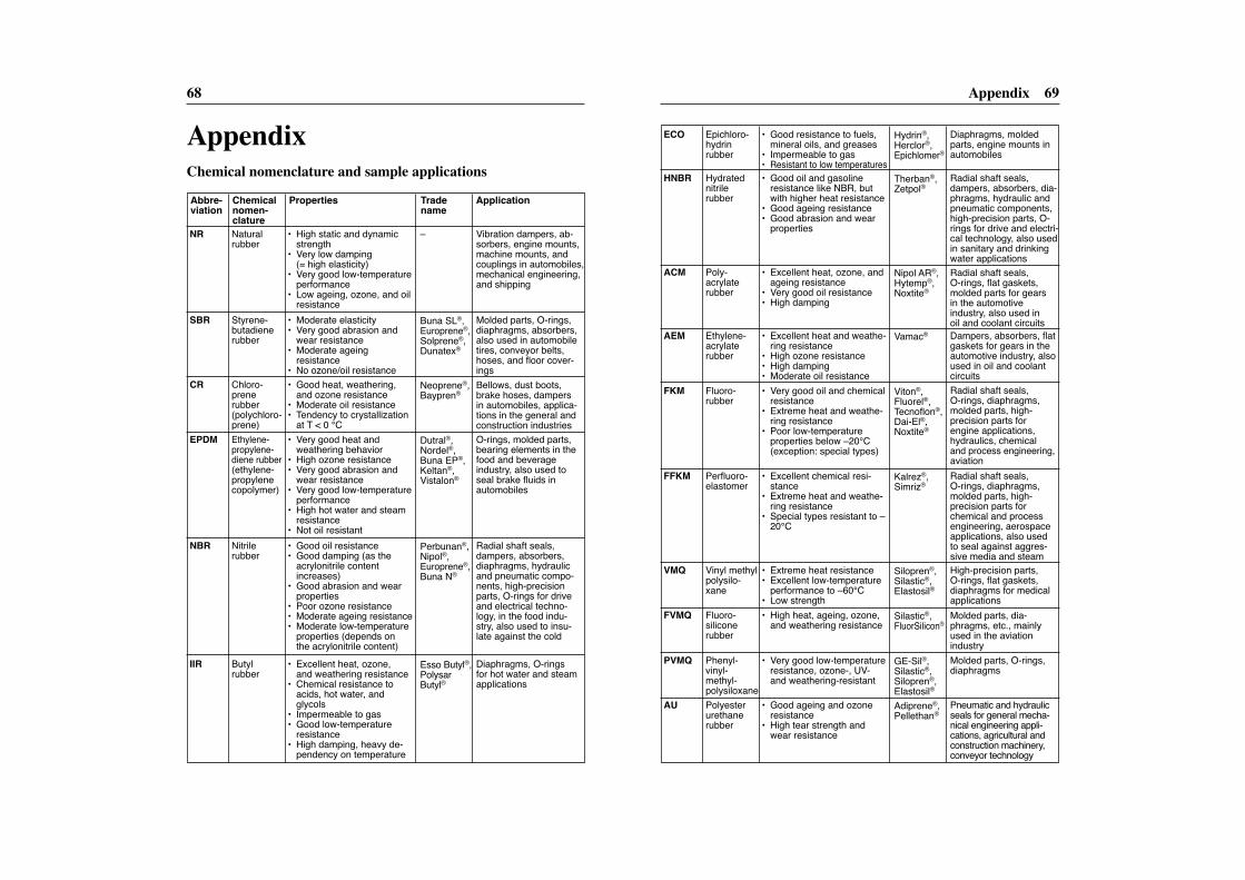
Appendix 6968
AppendixChemical nomenclature and sample applications
Natural rubber
• High static and dynamicstrength
• Very low damping (= high elasticity)
• Very good low-temperatureperformance
• Low ageing, ozone, and oilresistance
• Moderate elasticity • Very good abrasion and
wear resistance • Moderate ageing
resistance • No ozone/oil resistance• Good heat, weathering,
and ozone resistance• Moderate oil resistance • Tendency to crystallization
at T < 0 °C• Very good heat and
weathering behavior • High ozone resistance • Very good abrasion and
wear resistance • Very good low-temperature
performance• High hot water and steam
resistance• Not oil resistant• Good oil resistance • Good damping (as the
acry lonitrile content increases)
• Good abrasion and wearproperties
• Poor ozone resistance• Moderate ageing resistance • Moderate low-temperature
properties (depends on the acrylonitrile content)
• Excellent heat, ozone, and weathering resistance
• Chemical resistance toacids, hot water, and glycols
• Impermeable to gas• Good low-temperature
resistance• High damping, heavy de-
pendency on temperature
NR
SBR
CR
EPDM
NBR
IIR
Styrene-butadienerubber
Chloro-prene rubber (polychloro-prene)Ethylene-propylene-diene rubber (ethylene-propylenecopolymer)
Nitrile rubber
Butyl rubber
Abbre- Chemical Properties Trade Applicationviation nomen- name
clature–
Esso Butyl®, Polysar Butyl®
Perbunan®, Nipol®, Europrene®, Buna N®
Dutral®, Nordel®, Buna EP®,Keltan®, Vistalon®
Neoprene®,Baypren®
Buna SL®,Europrene®,Solprene®,Dunatex®
Vibration dampers, ab-sorbers, engine mounts,machine mounts, andcouplings in automobiles,mechanical engineering,and shipping
Molded parts, O-rings,diaphragms, absorbers,also used in automobiletires, conveyor belts, hoses, and floor cover-ingsBellows, dust boots,brake hoses, dampersin automobiles, applica-tions in the general andconstruction industriesO-rings, molded parts,bearing elements in thefood and beverage industry, also used toseal brake fluids in automobiles
Radial shaft seals, dampers, absorbers,diaphragms, hydraulicand pneumatic compo-nents, high-precisionparts, O-rings for driveand electrical techno-logy, in the food indu-stry, also used to insu-late against the cold
Diaphragms, O-rings for hot water and steamapplications
Epichloro-hydrin rubber
• Good resistance to fuels, mineral oils, and greases
• Impermeable to gas• Resistant to low temperatures• Good oil and gasoline
resistance like NBR, butwith higher heat resistance
• Good ageing resistance• Good abrasion and wear
properties
• Excellent heat, ozone, andageing resistance
• Very good oil resistance • High damping
• Excellent heat and weathe-ring resistance
• High ozone resistance • High damping • Moderate oil resistance • Very good oil and chemical
resistance • Extreme heat and weathe-
ring resistance• Poor low-temperature
properties below –20°C (exception: special types)
• Excellent chemical resi-stance
• Extreme heat and weathe-ring resistance
• Special types resistant to –20°C
• Extreme heat resistance • Excellent low-temperature
performance to –60°C• Low strength• High heat, ageing, ozone,
and weathering resistance
• Very good low-temperatureresistance, ozone-, UV-and weathering-resistant
• Good ageing and ozone resistance
• High tear strength andwear resistance
ECO
HNBR
ACM
AEM
FKM
FFKM
VMQ
FVMQ
PVMQ
AU
Hydratednitrile rubber
Poly-acrylaterubber
Ethylene-acrylaterubber
Fluoro-rubber
Perfluoro-elastomer
Vinyl methylpolysilo-xane
Fluoro -silicone rubber
Phenyl-vinyl-methyl-polysiloxanePolyesterurethanerubber
Hydrin®, Herclor®,Epichlomer®
Kalrez®, Simriz®
Silopren®,Silastic®,Elastosil®
Silastic®,FluorSilicon®
GE-Sil®, Silastic®,Silopren®,Elastosil®Adiprene®,Pellethan®
Viton®, Fluorel®,Tecnoflon®, Dai-El®, Noxtite®
Vamac®
Nipol AR®,Hytemp®, Noxtite®
Therban®, Zetpol®
Diaphragms, moldedparts, engine mounts inautomobiles
Radial shaft seals, dampers, absorbers, dia-phragms, hydraulic andpneumatic components,high-precision parts, O-rings for drive and electri-cal technology, also usedin sanitary and drinkingwater applicationsRadial shaft seals, O-rings, flat gaskets, molded parts for gearsin the automotive industry, also used in oil and coolant circuitsDampers, absorbers, flatgaskets for gears in theautomotive industry, alsoused in oil and coolantcircuitsRadial shaft seals, O-rings, diaphragms,molded parts, high-precision parts for engine applications, hydraulics, chemical and process engineering,aviationRadial shaft seals, O-rings, diaphragms,molded parts, high-precision parts for chemical and processengineering, aerospaceapplications, also usedto seal against aggres-sive media and steamHigh-precision parts, O-rings, flat gaskets,diaphragms for medicalapplicationsMolded parts, dia-phragms, etc., mainlyused in the aviation industryMolded parts, O-rings,diaphragms
Pneumatic and hydraulicseals for general mecha-nical engineering appli-cations, agricultural andconstruction machinery,conveyor technology
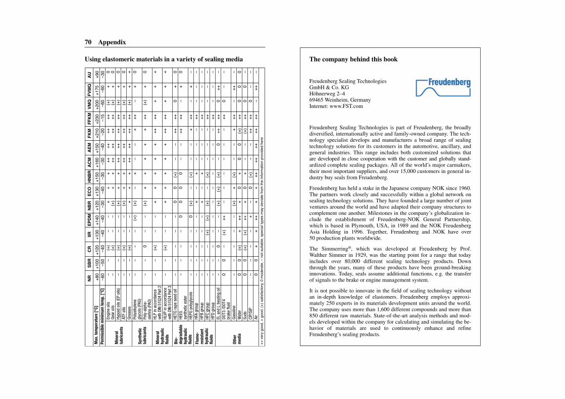
The company behind this book
Freudenberg Sealing Technologies GmbH & Co. KGHöhnerweg 2–469465 Weinheim, GermanyInternet: www.FST.com
Freudenberg Sealing Technologies is part of Freudenberg, the broadlydiversified, internationally active and family-owned company. The tech-nology specialist develops and manufactures a broad range of sealingtechnology solutions for its customers in the automotive, ancillary, andgeneral industries. This range includes both customized solutions thatare developed in close cooperation with the customer and globally stand-ardized complete sealing packages. All of the world’s major carmakers,their most important suppliers, and over 15,000 customers in general in-dustry buy seals from Freudenberg.
Freudenberg has held a stake in the Japanese company NOK since 1960.The partners work closely and successfully within a global network onsealing technology solutions. They have founded a large number of jointventures around the world and have adapted their company structures tocomplement one another. Milestones in the company’s globalization in-clude the establishment of Freudenberg-NOK General Partnership,which is based in Plymouth, USA, in 1989 and the NOK FreudenbergAsia Holding in 1996. Together, Freudenberg and NOK have over 50 production plants worldwide.
The Simmerring®, which was developed at Freudenberg by Prof.Walther Simmer in 1929, was the starting point for a range that todayincludes over 80,000 different sealing technology products. Downthrough the years, many of these products have been ground-breakinginnovations. Today, seals assume additional functions, e.g. the transferof signals to the brake or engine management system.
It is not possible to innovate in the field of sealing technology withoutan in-depth knowledge of elastomers. Freudenberg employs approxi-mately 250 experts in its materials development units around the world.The company uses more than 1,600 different compounds and more than850 different raw materials. State-of-the-art analysis methods and mod-els developed within the company for calculating and simulating the be-havior of materials are used to continuously enhance and refineFreudenberg’s sealing products.
70 Appendix
+80
+100
+120
+130
+140
+120
+130
+150
+160
+150
+210
+230
+200
+175
+90
–60
–50
–40
–40
–40
–30
–40
–30
–30
–40
–20
–15
–60
–60
–30
Engi
ne o
ils–
–(+
)–
–+
++
++++
++++
(+)
+0
Gear
oils
–(+
)–
–(+
)+
+++
++++
++(+
)+
0Hy
poid
oils
(EP
oils
)–
–(+
)–
–(+
)+
+++
++++
++(+
)+
0AT
F oi
ls–
–(+
)–
–(+
)+
+++
++++
++(+
)+
0Gr
ease
s–
–(+
)–
–+
++
++++
++++
(+)
++
Poly
alky
lene
––
––
(+)
(+)
–+
––
+++
–+
0gl
ycol
s (P
AG)
Poly
-alp
ha-
––
0–
–(+
)+
++
++
++(+
)+
0ol
efin
s (P
AO)
HLP
in a
ccor
danc
e–
–(+
)–
–+
++
++
++++
++
+w
ith D
IN 5
1524
Par
t 2HL
VP in
acc
orda
nce
––
(+)
––
++
++
+++
+++
++
with
DIN
515
24 P
art 3
HETG
rape
see
d oi
l–
––
––
00
(+)
––
++++
0+
0HE
ES
––
––
00
00
––
++++
–+
0sy
nthe
tic e
ster
HEPG
pol
ygly
cols
––
––
0(+
)–
(+)
––
+++
–+
–HF
A gr
oup
––
––
–+
–+
––
–++
––
–HF
B gr
oup
––
––
–+
–+
––
–++
––
–HF
C gr
oup
––
–(+
)(+
)(+
)–
(+)
––
–++
––
–HF
D gr
oup
––
––
––
––
––
–++
––
–EL
and
L h
eatin
g oi
l–
–0
––
(+)
(+)
(+)
–0
++++
0++
–DO
T3 /D
OT4
00
–(+
)++
––
––
––
++0
––
brak
e flu
idGa
solin
e–
––
––
(+)
+(+
)–
–+
++–
++–
Wat
er0
0(+
)+
+++
0+
00
(+)
++0
00
Suds
00
(+)
(+)
+++
0+
––
(+)
++0
0–
CIP/
SIP
––
––
+–
0(+
)–
–++
++0
––
Air
00
++
+++
+++
++++
++++
–++
–++
very
goo
d, +
goo
d, (+
) sat
isfac
tory,
0 m
oder
ate,
– n
ot su
itable
; spe
cial ty
pes m
ay d
eviat
e fro
m th
e inf
orm
ation
pro
vided
her
e
Min
eral
hydr
aulic
fluid
s
Min
eral
lubr
ican
ts
Synt
hetic
lubr
ican
ts
Bio-
degr
adab
lehy
drau
licflu
ids
Flam
e-re
sist
ant
hydr
aulic
fluid
s
Othe
rm
edia
NRSB
RCR
IIREP
DMNB
REC
OHN
BRAC
MAE
MFK
MFF
KMVM
QFV
MQAU
Max
. tem
pera
ture
[°C]
Perm
issi
ble
min
imum
tem
p. [°
C]
Using elastomeric materials in a variety of sealing media