vibrating process equipment for resource recovery
TRANSCRIPT
VIBRATING PROCESS EQUIPMENT FOR RESOURCE
RECOVERY
ALBERT MUSSCHOOT, RAYMOND SHERMAN, AND WILLIAM GUPTAIL General Kinematics Corporation
Barrington, Illinois
ABSTRACf
An overview of many waste streams and the manner
in which technically advanced vibrating process equipment is used to assist in the recovery recyclable materi
als. Special equipment designs efficiently convey, separate and classify a wide range of materials for further
processing while minimizing the volume of material
destined for landfill.
TODAY'S CHALLENGE
Massive amounts of waste are produced daily throughout the United States, and some areas of the
country have run out of places to put it. Many landfills
have closed, and those remaining are rapidly reaching
capacity. New facilities are difficult to establish because
of environmental concerns and widespread public op
position. The days of our "throw-away" society have
ended and the start of various types of recycling pro
grams has led to the development of new, virtually unexplored applications for processing equipment.
The initial goal of most recycling programs is to
reduce landfill volume; however, as programs have ma
tured, a growing secondary market for recyclables has
developed. Once the volume of these relatively easy to
recover materials increases, the volume of residuals
directed to landfill will be reduced. Today, vibrating equipment is playing an important part in speeding the
recovery and enrichment of waste streams by reducing
9
the need for manual separation and classification of
valuable recyclable materials.
VIBRATING EQUIPMENT
Traditionally, vibration has had a negative connota
tion and been viewed as something that had to be elimi
nated; however, it is fortunate that a few inquisitive
engineers saw vibration as a possible means of moving
and processing bulk materials. Although various forms
of vibrating conveying have been used in the United States for over a century, it has been only in the past
few decades that the concepts of vibrating conveying
and processing have achieved full industry acceptance. Recent advancements in high strength space-age mate
rials and technological skills have fueled a development
in the design of single, multipurpose vibrating machines which reduce material handling by combining various
processes to increase productivity while reducing costs.
Current vibrating equipment designs, with very few
exceptions, utilize the principle of natural frequency operation to minimize force input and reduce con
nected horsepower requirements, resulting in low en
ergy demand.
Vibrating equipment has a long successful record in tough applications within the foundry, steel, coal,
mining, and scrap industries where its ability to provide reliable, low-maintenance performance is highly re
garded. The past few years have seen this same proven technology directed to development of special vibrating

machines within the expanding waste recovery and re
cycling industries. Almost daily, new concepts for the processing of
various selected waste streams seem to arrive on the
scene and vibrating equipment designs have kept pace.
Some current vibrating process equipment designs did
not even exist less than a year ago. Manufacturers of vibrating equipment have typically
kept their engineering analysis and design techniques
confidential and many of these newly developed machines are considered proprietary designs which have been patented or have patents pending.
BENEFITS OF VIBRATORY MOTION
Material on a vibrating conveyor is "live" and moves
independently of the conveying medium, whereas on
other types of conveyors, the material is static and the
conveying medium moves. This important characteris
tic provides a solution to many difficult material han
dling and processing applications facing us in today's growing Solid Waste Processing Industry.
The proper combination of amplitude, the total
movement of the material carrying deck, and fre
quency, the number of cycles of motion for a given time
period, together with the angle in which the resulting
force is applied, can provide an aggressive tossing ac
tion all the way down to a gentle sliding-type movement depending upon the motion needed to meet processing
requirements. Abrasive wear is minimized, since the
vertical accelerating force applied to the material re
duces its effective pressure on the trough surface.
The ability to perform multiple supplemental func
tions such as screening or classifying, aligning, and turning material while conveying, along with provi
sions to discharge material at intermediate positions,
provides a compact, economical solution to a variety
of new processing demands.
INSTALLATION CONCERNS
The assumption that vibrating equipment requires
massive foundations and/or support structures is no
longer valid. Currently, a variety of balancing systems designs, with varying degrees of isolation efficiency, are
available to reduce transmitted vibration. Some state
of-the-art designs even respond directly to changes in material loading thus assuring balanced operation at
all times.
Steel support structures can now be designed based
primarily upon static loading with only secondary con-
10
FIG. 1 ELECTRONIC STROKE MONITOR WITH VIBRATION SENSING TRANSDUCER PROVIDES
REMOTE INDICATION OF VIBRATING UNIrS OPERATION AND PROVIDES WARNING WHEN
CONDITIONS CHANGE
sideration given to the degree of dynamic loading and the range of exciting frequencies involved.
PERFORMANCE MONITORING
A valuable accessory to complement any vibrating
equipment installation is a digital feedback control
which provides reliable and continuous monitoring of stroke amplitude. A typical unit is shown in Fig. 1.
This device is ideal for monitoring the performance of
vibrating units in inaccessible locations, especially those subjected to surge load conditions or those han
dling materials which may tend to build up on the trough surface. The monitor senses either an over or
understroke condition so that immediate action can be
taken to prevent equipment damage and loss of pro
duction.
A transducer mounted to the vibrating surface pro
vides amplitude input sensing, a design adaptable to
any vibrating machine. The solid state control has a bright LED readout
showing actual operating stroke and dual push buttons
to display preset high and low stroke parameters. These set points are fully adjustable allowing the monitor to
be tuned to each specific application. Control output is
in the form of a 4-20 ma analog signal with a separate signal indicating whether the deviation from normal
operation occurred in either the high or low stroke
condition.
BIO·MASS FUELS
The recent slowdown in the forest products industry
and the accompanying controversy over the Spotted
Owl habitat, has resulted in a severe shortage of fuel
for Bio-Mass fuel burning boilers. This has forced oper
ators to search out new sources of acceptable fuel in
order to stay on stream. Today, material never before
considered as a viable source of fuel, old abandoned
bark piles for example, can be enhanced by the removal
of dirt, stones and other noncombustible contaminants. In addition to providing an acceptable supply of fuel,
reduced boiler service and slower clinker buildup are
among the benefits provided by a hog fuel and
woodyard waste, dry process, cleanup system. A dry .
system, besides being more economical, eliminates
water handling, saturated bark and other problems as
sociated with wet separation systems. Field experience
shows a dramatic reduction in clinker buildup rate and substantially reduced ash contents when burning pro
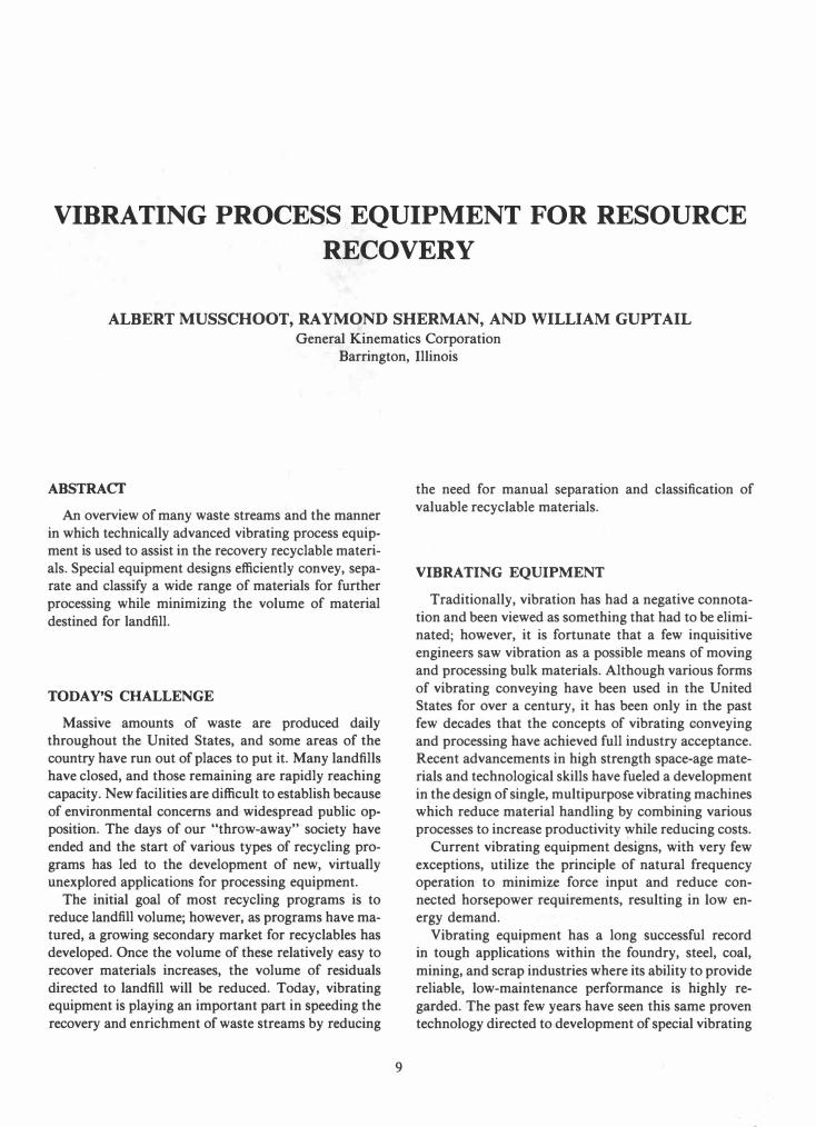
cessed log yard or bark pile waste. Undesirable fine material, which is mostly dirt, is
removed from yard cleanup material by a vibrating finger screen design (Fig. 2), providing a cascading
material flow across a series of self-relieving finger ele
ments. Material which would hangup or catch in a
conventional perforated or wire mesh screen is effi
ciently separated without difficulty. The "fines" passing
through are an ideal mulching material.
A combination vibrating/pneumatic air-knife classi
fying unit identified as a De-Stoner (Fig. 3), separates and classifies the remaining fuel on the basis of density
and particle size. A combination of vibration and high velocity air streams fluidize and stratify material prior to its being exposed to either single or dual air-knife
curtains for thorough separation of unwanted material.
The unit's vibrating action causes a natural separation where lighter material particles move upwards while
heavier particles move to the bottom of the material
bed. This initial separation is improved by blowing a high velocity stream of air through the bed of material just prior to exposing it to an air-knife angled in the
direction of flow. An adjustable air current from the
knife carries lighter particles across an adjustable
drop-out gap, while heavier pieces fall into the gap and are discharged. The separator is virtually jam-proof,
since there are no moving parts. Stones and other coarse
"reject" material can be used as yard cover or directed
to landfill.
1 1
The bio-mass fuel screening and classifying machines
are energy efficient with a typical system using a total of less than 50 hp. Their balanced isolated designs elim
inate the need for elaborate foundations and support
structures, allowing simple, economical installation.
AUTO SHREDDER FLUFF (ASR)
Vibrating recovery equipment has recently been ap
plied to the processing of automobile shredder residue
(ASR) or "auto-fluff" as it is sometimes identified. Field experience has shown that this material, the remnants
of shredded automobile bodies after magnetic separa
tion and processing through various styles of reverse
air-flows separators, may contain 5% or more of "heav
ies" of which up to 30% of this volume consists of
additional ferrous and nonferrous material. The usual
procedure is to magnetically separate shredded ferrous
material from the shredder discharge flow and then
process the remaining material through a gravity-style
reverse air-flow separator to remove any ferrous mate
rial missed by the initial magnets plus nonferrous mate
rial which may be present. The residual "fluff" material
is then disposed of in a landfill.
It is difficult to maintain separation efficiency on this
type of air separator, since if the ratio of air-flow to
material flow is too high, smaller pieces of metal scrap
will be carried out with the light "fluff", plastics, etc.
Should the air-flow ratio be too low, "fluff" material
drops out with the heavier metal necessitating addi
tional cleanup.
When a vibrating/pneumatic air-knife classifier is
installed (Fig. 4), the reverse air-flow separator can be
adjusted to provide maximum efficiency on the clean
metal side and the metal contaminated "fluff" pro
cessed across the vibrating unit to remove all carryover
ferrous and nonferrous material.
Field operation has shown the "fluff" processed
across a vibrating air-knife to be virtually free of metal
although upon occasion a piece of wire or aluminum
trim will be caught in a "fluff ball" and carried out with it. Also, should a small piece of aluminum door trim
enter the air stream in a specific attitude, it too may be
carried out with the "lights".
A finger screen can be installed prior to the classifying unit to scalp off larger pieces of plastic, hose, insula
tion and sponge rubber to improve separation effi
ciency. Recent testing reveals that it may be possible
to achieve additional high density separation from the
processed light "fluff" stream.

FIG.2 TYPICAL FINGER SCREEN DECK WHERE MATERIAL CASCADES ACROSS SERIES OF OVERLAPPING TAPERED FINGERS. SIZE, NUMBER AND DESIGN OF FINGER SCREENS ARE DETERMINED BY APPLICATION
REQUIREMENTS.
CONSTRUCfION/DEMOLITION (C/D)
WASTE
Efficient dry separation and classification of con
struction/demolition waste is now possible, allowing the reclamation of recyclables while concurrently reducing the volume of material destined for a landfill.
Existing reclamation systems are handling material at
rates up to 15,000 cu ft/hr.
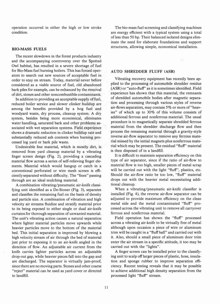
In a typical system (Fig. 5), construction/demolition
material on a tipping floor is moved within reach of
pivoting grapple loader which moves bulky undesirable
material like tires and storage batteries to a refuse container. Remaining material is placed on a crusher feeder
which meters it into the crusher. A vibrating feeder installed below the crusher, con
trols the feed of crushed material to an inclined belt conveyor which discharges to a conveyor incorporating
a finger screen deck. The various size crushed materials
which would otherwise catch in a conventional perfora
ted or wire mesh screen, are efficiently separated by
12
the vibrating cascading material flow over a series of
self-relieving finger elements which remove minus 3/4
in. material for landfill cover. The deck may occasion
ally include a series of vertically spaced steps between
screen sections to aid in the turnover of material as it
drops onto the following section. Large bulky items
and other undesirable materials, such as carpeting or
tangled wire which bypass the crusher, are manually
removed to containers.
Material remaining on finger deck passes below over
head in-line magnet, which discharges ferrous material
into material container and allows the remaining mate
rial to discharge onto an innovative vibrating/pneu
matic air-knife classifying unit, a De-Stoner, which sep
arates and classifies mixed bulk materials on the basis
of density and particle size.
Additional manual sorting can be accomplished on
inlet portion of this unit, if desired. Material is fluidized
and stratified by both vibration and high velocity air
streams prior to being exposed to dual air-knife curtains

1
How it works
2 3 5 8
1. Material moves along conveyor by vibratory action with high density material settling to bottom of trough.
4. High velocity, low pressure air stream is directed through material flow.
7. Acceptable material carries beyond plate and travels through conveyor to discharge.
2. Pre-classifier conveyor section (optional) removes smaller particle sizes before reaching air fluidizer.
5. Material conveys into air stream . Heavy material falls through air stream to secondary separator.
8. Secondary separator continues separating process to assure thorough and complete classification.
3. Air fluidizing section assists in stratifying material.
�. Marginal density material is caught on adjustable slope plate and falls back into secondary separator.
9. High density refuse material is removed from conveyor through side discharge.
FIG.3 MATERIAL FLOW IN DUAL AIR-KNIFE CLASSIFIER
for thorough separation. Paper, light plastics and re
maining fines are carried by the airstream within the
hood to a cyclone and dust control system. Heavy mate
rials, brick, glass, tile, broken concrete, nonferrous metal, heavy plastic, etc. are side discharged to inclined
vibrating conveyor. Lighter material, primarily wood
products, is end discharged ready for further processing or use as ground cover or boiler fuel.
Inclined V-trough vibrating conveyor discharges heavy material from the classifying unit onto an ele
vated sorting conveyor, where an overhead cross belt
magnet removes residual ferrous material. A final man
ual sorting operation recovers nonferrous and other
recyclable materials.
Reduced volume of residue from this final sorting operation is directed to landfill.
13
WASTE-TO-ENERGY (WTE)
For many years, vibrating equipment has demon
strated outstanding reliability in demanding mass burn
bottom ash applications. Despite corrosive atmo
spheres, variable load conditions, high impact, heat and
moisture, specially designed vibrating conveyors keep
material moving around the clock, day after day!
In a typical mass bum bottom ash handling system
(Fig. 6), long balanced vibrating conveyors receive
quenched ash from a series of dischargers. These con
veyors have smooth, continuous, alloy steel replaceable
decks entirely free of steps, ledges or other obstructions
which could hinder material movement. The 'sectional
design of the replaceable deck allows the use of thicker
steel in areas of high impact loading. The units are

FIG.4 VIBRATING/PNEUMATIC CLASSIFIER <Destoner) WITH DUAL KNIVES HAS A BALANCED DESIGN TO ELIMINATE FOUNDATION CONCERN. LARGE VOLUME H OOD WITH AIR TAKEOFF CONTROLS AIRBORNE
PARTICLES.
capable of sequenced start/stop operation synchro
nized with operation of the ash dischargers.
Bulky oversize material in the bottom ash is removed
by a grizzly scalper having tapered openings designed
to prevent hangups. This separation can be accom
plished as an integral part of the collecting conveyor
or be done on a separate machine. A market is developing for these post combustion products. Following
the removal of oversize items, the ash is processed across a vibrating finger screen to remove minus 1 in. for further utilization and/or stabilization.
More efficient magnetic recovery of ferrous material
and eddy-current extraction of nonferrous material is
achieved because of the reduced volume of cleaner,
fines-free ash being processed.
The remaining reduced volume of processed ash is distributed across several storage bunkers in the ash
load-out facility by a balanced vibrating conveyor
equipped with a series of intermediate, air-operated
bottom drop out gates. Additional cleanup of both the recovered ferrous
and nonferrous scrap can be accomplished by a special
inclined vibrating unit equipped with a large volume
water tank and spray nozzles. This unit washes residual
14
ash from the reclaimed metals to further enhance their
value.
Concern about foundation and support structures,
as well as possible damage to surrounding equipment,
is minimized since all the units have a balanced design
utilizing the principle of natural frequency operation to fully compensate for varying material loads.
SCRAP PROCESSING
The heavy loading and abusive conditions encountered in most scrap recycling facilities are a natural
for the inherent ruggedness of vibrating equipment.
Currently, various design vibrating units are used to
feed material to, and accept the discharge from, alliga
tor and guillotine shears, convey processed scrap beneath magnets, through manual sorting operations, and
withstand the severe impact below automobile
shredders.
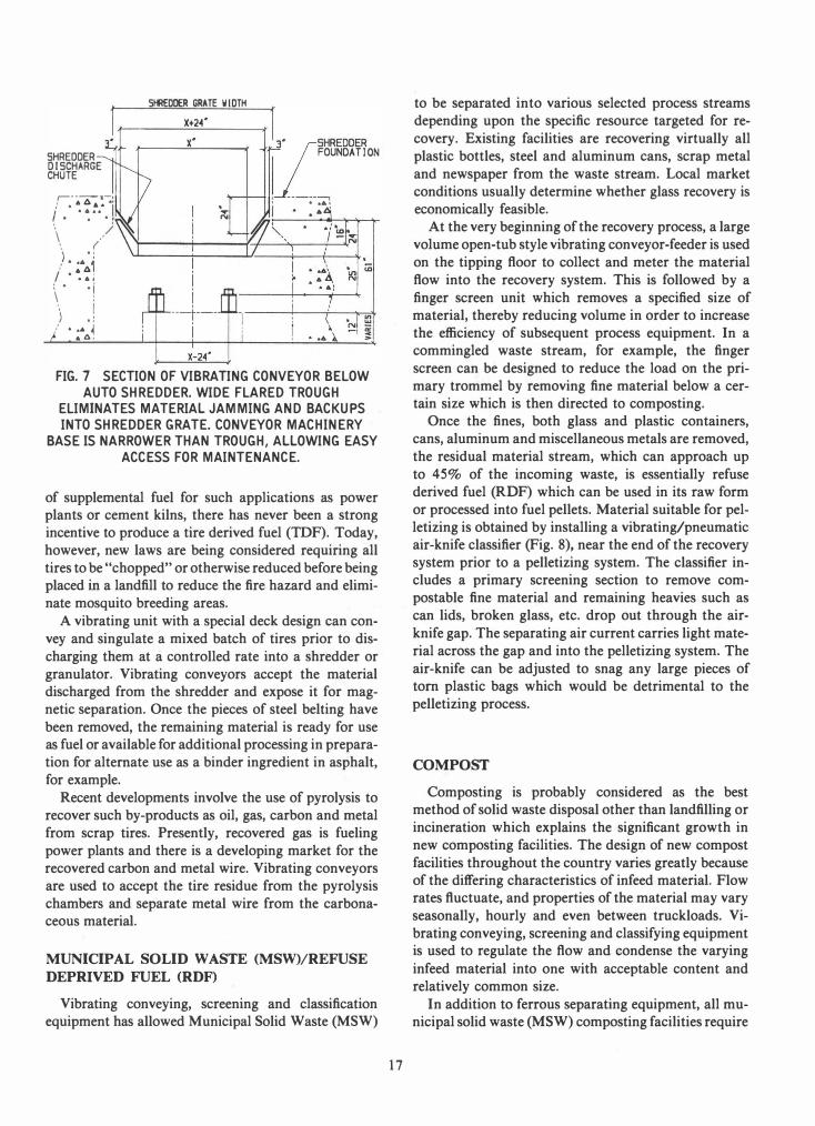
Vibrating decks are tailored to each specific applica
tion. A typical automobile shredder discharge conveyor
(Fig. 7), for example, is positioned with minimum clear
ance between the shredder foundation side walls. It is
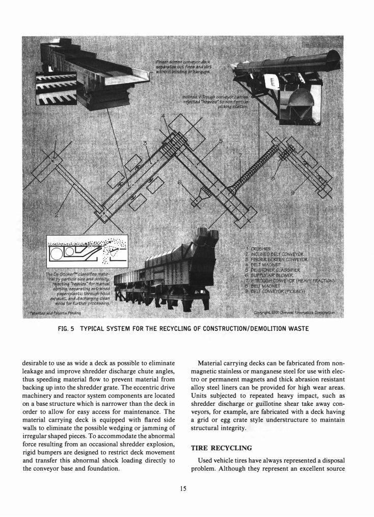
FIG.5 TYPICAL SYSTEM FOR THE RECYCLING OF CONSTRUCTION/DEMOLITION WASTE
desirable to use as wide a deck as possible to eliminate
leakage and improve shredder discharge chute angles,
thus speeding material flow to prevent material from
backing up into the shredder grate. The eccentric drive
machinery and reactor system components are located on a base structure which is narrower than the deck in
order to allow for easy access for maintenance. The material carrying deck is equipped with flared side
walls to eliminate the possible wedging or jamming of irregular shaped pieces. To accommodate the abnormal
force resulting from an occasional shredder explosion,
rigid bumpers are designed to restrict deck movement
and transfer this abnormal shock loading directly to the conveyor base and foundation.
15
Material carrying decks can be fabricated from non
magnetic stainless or manganese steel for use with electro or permanent magnets and thick abrasion resistant
alloy steel liners can be provided for high wear areas.
Units subjected to repeated heavy impact, such as
shredder discharge or guillotine shear take away conveyors, for example, are fabricated with a deck having a grid or egg crate style understructure to maintain
structural integrity.
TIRE RECYCLING
Used vehicle tires have always represented a disposal
problem. Although they represent an excellent source
2.
Tapered bar griZZly deck reduces malenal hangup wnlle knocking ash from oversize material.
l'ypicaIUh dl..,h_rge from below bcMlerg ....
4 "j
6
Dlatrlbutlon vibnollng conveyor has bottom diSCharge for POSitive malenal transfer to bunkers.
I CONVEYOR FROM ASH DISCHARGERS
2 GRIZZLY SCALPER
3 V18RATING FEEDER
.. INCLINED 8EL T CONVEYOR
� FINGER SCREEN
6 8UNKER DISTRI8UTION CONVEYOR
7 DRUM MAGNET
& FERROUS MATERIAL
9 NON-FERROUS MATERIAL
FIG. 6 TYPICAL WASTE-TO-ENERGY SYSTEM
16
SHREDDER DISCHARGE CHUTE
.----.-' • 0\ t:. 0\. AI
" '..... 1 .. .
. , .. ) \ .'
.. . (
)
.
.
..
l'
, .. A.o., / .... :. ·1 \ : " 1 ) . : : .... 1
.. b.,
SHREDDER GRATE WIDTH
·1,. �SHREODER
I� __ .. FDUND'TIDN
I --------,
i . .• :
• • 6
FIG.7 SECTION OF VIBRATING CONVEYOR BELOW AUTO SHREDDER. WIDE FLARED TROUGH
ELIMINATES MATERIAL JAMMING AND BACKUPS INTO SHREDDER GRATE. CONVEYOR MACHINERY
BASE IS NARROWER THAN TROUGH, ALLOWING EASY ACCESS FOR MAINTENANCE.
of supplemental fuel for such applications as power plants or cement kilns, there has never been a strong
incentive to produce a tire derived fuel (TDF). Today,
however, new laws are being considered requiring all
tires to be "chopped" or otherwise reduced before being placed in a landfill to reduce the fire hazard and elimi
nate mosquito breeding areas.
A vibrating unit with a special deck design can con
vey and singulate a mixed batch of tires prior to dis
charging them at a controlled rate into a shredder or
granulator. Vibrating conveyors accept the material discharged from the shredder and expose it for magnetic separation. Once the pieces of steel belting have
been removed, the remaining material is ready for use as fuel or available for additional processing in prepara
tion for alternate use as a binder ingredient in asphalt,
for example.
Recent developments involve the use of pyrolysis to
recover such by-products as oil, gas, carbon and metal
from scrap tires. Presently, recovered gas is fueling
power plants and there is a developing market for the recovered carbon and metal wire. Vibrating conveyors
are used to accept the tire residue from the pyrolysis
chambers and separate metal wire from the carbonaceous materiaL
MUNICIPAL SOLID WASTE (MSW)/REFUSE
DEPRIVED FUEL (RDF)
Vibrating conveying, screening and classification equipment has allowed Municipal Solid Waste (MSW)
17
to be separated into various selected process streams
depending upon the specific resource targeted for re
covery. Existing facilities are recovering virtually all
plastic bottles, steel and aluminum cans, scrap metal
and newspaper from the waste stream. Local market
conditions usually determine whether glass recovery is economically feasible.
At the very beginning of the recovery process, a large
volume open-tub style vibrating conveyor-feeder is used
on the tipping floor to collect and meter the material
flow into the recovery system. This is followed by a
finger screen unit which removes a specified size of
material, thereby reducing volume in order to increase
the efficiency of subsequent process equipment. In a commingled waste stream, for example, the finger
screen can be designed to reduce the load on the pri
mary trommel by removing fine material below a cer
tain size which is then directed to composting.
Once the fines, both glass and plastic containers,
cans, aluminum and miscellaneous metals are removed,
the residual material stream, which can approach up
to 45% of the incoming waste, is essentially refuse
derived fuel (ROF) which can be used in its raw form
or processed into fuel pellets. Material suitable for pel
letizing is obtained by installing a vibrating/pneumatic air-knife classifier (Fig. 8), near the end of the recovery
system prior to a pelletizing system. The classifier includes a primary screening section to remove com
postable fine material and remaining heavies such as
can lids, broken glass, etc. drop out through the air
knife gap. The separating air current carries light mate
rial across the gap and into the pelletizing system. The
air-knife can be adjusted to snag any large pieces of tom plastic bags which would be detrimental to the
pelletizing process.
COMPOST
Composting is probably considered as the best method of solid waste disposal other than landfilling or
incineration which explains the significant growth in
new composting facilities. The design of new compost
facilities throughout the country varies greatly because of the differing characteristics of infeed materiaL Flow rates fluctuate, and properties of the material may vary
seasonally, hourly and even between truckloads. Vi
brating conveying, screening and classifying equipment is used to regulate the flow and condense the varying
infeed material into one with acceptable content and
relatively common size.
In addition to ferrous separating equipment, all municipal solid waste (MSW) composting facilities require

How it works 1
2
1. Vibratory action moves material, with high density material settling to bottom of trough.
3. Air fluidizing section assists in stratifying material.
adjustable slope plate and falls back into discharge chute.
2. Fines drop out section (optional) removes smaller particle sizes of broken glass and dirt before reaching air fluidizer.
4. High velocity, low pressure air stream is directed through material flow.
7. Acceptable material such as aluminum and plastic carries beyond plate and travels to product discharge. 5. Material conveys into air stream. Hea
vy material such as glass and metal falls through air stream to discharge chute.
S. Light material, paper and plastic film is removed through air exhaust on stationery hood over discharge. 6. Marginal density material is caught on
FIG.8 MATERIAL FLOW IN SINGLE AIR-KNIFE CLASSIFIER
some form of coarse screening. Whether the material
is raw MSW or preprocessed material, it is necessary
to remove a specific size of unwanted oversize items.
These can be further reduced in size for re-entry into
the process system or otherwise disposed of. The jam
free, nonblinding, cascading flow action of a vibrating
finger screen unit is ideal for screening mixed materials
having different sizes and physical characteristics.
At some point in the composting process, it is sometimes desirable to "fine" screen the fermenting compost
in order to enhance the final product. Again, the efficient performance of a vibrating finger screen is ideal.
A vibrating/pneumatic air-knife classifier is also used to remove undesirable material, such as glass
shards, plastics and nonferrous metallics, from the ma
ture compost.
18
MATERIAL RECYCLING FACILITY (MRF)
Vibrating equipment is being applied to many new applications within the emerging resource recovery industry, especially as recyclers search for more cost effective ways to develop selected waste streams using minimum manpower.
Vibrating process machines are easily adapted for this service and their design varies from one facility to the next because of their intended purpose in the operation and the many possible variations in the incoming material flow. The infeed material may consist of source separated, dirty or relatively clean commingled mixed containers and paper stock, construction/ demolition or even metal scrap!
The ability of a single-knife vibrating/pneumatic classifier (Fig. 9), to separate glass from aluminum and
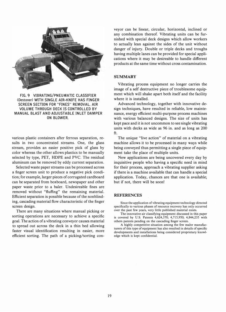
FIG.9 VIBRATING/PNEUMATIC CLASSIFIER <Destoner) WITH SINGLE AIR-KNIFE HAS FINGER SCREEN SECTION FOR "FINES" REMOVAL. AIR VOLUME THROUGH DECK IS CONTROLLED BY
MANUAL BLAST AND ADJUSTABLE INLET'DAMPER
ON BLOWER.
various plastic containers after ferrous separation, re
sults in two concentrated streams. One, the glass
stream, provides an easier positive pick of glass by color whereas the other allows plastics to be manually
selected by type, PET, HDPE and PVC. The residual
aluminum can be removed by eddy current separation.
Selected waste paper streams can be processed across a finger screen unit to produce a negative pick condi
tion; for example, larger pieces of corrugated cardboard
can be separated from boxboard, newspaper and other
paper waste prior to a baler. Undesireable fines are
removed without "fluffing" the remaining material. Efficient separation is possible because of the nonblind
ing, cascading material flow characteristic of the finger
screen design. There are many situations where manual picking or
sorting operations are necessary to achieve a specific
goal. The action of a vibrating conveyor causes material to spread out across the deck in a thin bed allowing
faster visual identification resulting in easier, more
efficient sorting. The path of a picking/sorting con-
19
veyor can be linear, circular, horizontal, inclined or any combination thereof. Vibrating units can be fur
nished with special deck designs which allow workers
to actually lean against the sides of the unit without
danger of injury. Double or triple decks and troughs
having multiple lanes can be provided for special applications where it may be desireable to handle different
products at the same time without cross contamination.
SUMMARY
Vibrating process equipment no longer carries the
image of a self destructive piece of troublesome equipment which will shake apart both itself and the facility
where it is installed.
Advanced technology, together with innovative de
sign techniques, have resulted in reliable, low maintenance, energy efficient multi-purpose process machines with various balanced designs. The size of units has kept pace and it is not uncommon to see single vibrating
units with decks as wide as 96 in. and as long as 200 ft.
The unique "live action" of material on a vibrating
machine allows it to be processed in many ways while
being conveyed thus permitting a single piece of equipment take the place of multiple units.
New applications are being uncovered every day by inquisitive people who having a specific need in mind
for their process, approach a vibrating supplier asking
if there is a machine available that can handle a special
application. Today, chances are that one is available; but if not, there will be soon!
REFERENCES
Since the application of vibrating equipment technology directed specifically to various phases of resource recovery has only occurred over the past few years, very little published material exists.
The innovative air classifying equipment discussed in this paper is covered by U.S. Patents 4,624,370; 4,715,950; 4,844,235 with others patents pending on the cascading finger screen.
A highly competitive situation among the few major manufacturers of this type of equipment has also resulted in details of specific developments and installations being considered proprietary knowledge which is kept confidential.