vibration analysis of heat exchanger using · pdf file1 a dissertation report on vibration...
TRANSCRIPT

1
A Dissertation Report on
VIBRATION ANALYSIS OF HEAT EXCHANGER USING CFD
For the requirement of the degree of
MASTER of TECHNOLOGY with the specialization Thermal system design
Guided By:
Mr. A.B.Makwana, Mr. R.D.Shah,
Mech. Engg. Department
Submitted By:
Patadiya Dharmeshkumar M. (P07TD152) M.Tech. (Thermal system design), III
rd Semester
(Academic Year: 2008-09)
Department of Mechanical Engineering
Sardar Vallabhbhai National Institute of Technology
SURAT – 395007 (Gujarat)
2
Sardar Vallabhbhai National Institute of Technology
SURAT – 395007 (Gujarat)
Mechanical Engineering Department
CERTIFICATE
This is to certify that the dissertation report entitled “Vibration analysis of heat
exchanger using CFD” is bonafide work carried out by Patadiya Dharmeshkumar M
(P07TD152) student of M.Tech. Thermal system design IVth Semester in partial
fulfillment of the requirement of the degree of MASTER of TECHNOLOGY with
the specialization Mechanical Engineering from Sardar Vallabhbhai National
Institute of Technology SURAT ,Gujarat This dissertation report is record of his
own work carried out under my supervision and guidance.
Guided By Head of The Department
Mr. A.B.Makwana,
Mr. R.D.Shah Dr. R.V. Rao
Mech. Engg. Deptt Mech. Engg. Deptt
3
EXAMINERS APPROVAL CERTIFICATE
This is to certify that the dissertation report entitled “Vibration analysis of heat
exchanger using CFD” is bonafide work carried out by Patadiya Dharmeshkumar
M (P07TD152) student of M.Tech. Thermal system design IVth Semester in partial
fulfillment of the requirement of the degree of MASTER of TECHNOLOGY with
the specialization Thermal System Design from Sardar Vallabhbhai National
Institute of Technology SURAT, Gujarat is approved.
Signature of Examiners
1.
2.
3.

4
ACKNOLEDGEMENT
I wish to express my sincere gratitude, regards and thanks to my respected project
guide Mr. A.B.Makwana and Mr. R.D.Shah for his excellent guidance and
unstinted support. It is my achievement to be guided by him. He is a constant source
of encouragement and momentum that any intricacy becomes simple. I gained a lot
of invaluable guidance and prompt suggestions from him during my seminar work. I
remained of him forever and I take a pride to work under him. I am also thankful to
the B.Tech. VIII student Mr. Shaswat Saincher (U05ME671) for his guidance. I am
also thakful to M.Tech.(Turbomachines) student Mr. Patel Divyesh (P07tm110) for
his guidance in doing this dissertation.
Patadiya Dharmeshkumar M

5
INDEX
1. Introduction 1
2. Literature review 2
3. Theory 7
Flow distribution calculation 7
Dynamic parameter evaluation 8
Vibration excitation mechanism 12
Vibration response prediction 13
Fretting wear assessment. 14
Mathematical model. 15
4. Objective of the project 18
5. References. 22
6
M.Tech. dissertation Preliminary report
On
“Vibration analysis of heat exchanger using
CFD”
Name of Student Name of guide
Patadiya Dharmeshkumar M Mr A.B. Makwana
( P07TD152) Mr R.D. Shah.
ABSTRACT Vibration is most common phenomena in our day to day life. This is also observed in
shell and tube heat exchanger (H.E). The fluids are flowing in shell and tube H.E for
heat transfer. When fluid flows across the tubes, induces vibration in the tubes. This is
called flow induced vibration. The drag and lift forces play a significant role in flow
induced vibration. The effect of flow induced vibration in heat exchanger can be
realized by drastic requirement in power and roaring sound in heat exchanger. The
sound is so strong that it can be heard in the area of 10 to 15 m circle.
Earlier investigations were carried out to study parameters effecting vibration in H. E.
The heat exchanger vibration analysis consists of following steps: (i). Flow
distribution calculation. (ii) Dynamic parameter evaluation like damping, effective
tube mass and hydraulic mass. (iii) Formulation of Vibration excitation mechanism
like acoustic resonance, random excitation, periodic wake shedding.(iv) Vibration
response prediction due to fluid elastic instability and (v) resulting damage
assessment. Theoretical analysis is having its own limitations. Numerical analysis are
widely accepted for such complex engineering problem.
The aim of present study is to make vibration analysis of shell and tube heat
exchanger numerically. For better understanding of problem solving using standard
software a benchmark problem is considered. The problem consisted of 2-D cylinder
in air flow. Fluent is use for solver, GAMBIT is used for preprocessor. Geometry
modeling and mesh generation is done in Gambit. Unstructured type of grid is use.
Results are presented for pressure sound intensity in decibel (db) and Power Spectral
Density. Strouhal number is the key parameter for calculation of natural frequency.
Graphical results obtained from present work is presented.

7
CHAPTER .1
INTRODUCTION Flow-induced vibration in heat exchangers has been a major cause of concern in the
nuclear industry for several decades. Some examples of tube failures in commercial
steam generators are reported in the review by Pettigrew and Taylor (1991). Almost
all heat exchangers have to deal with this problem during their operation. The
phenomenon has been studied since the 1970s. The database of experimental studies
on flow-induced vibration is constantly updated with new findings and improved
design criteria for heat exchangers. In the nuclear industry, steam generators are often
affected by this problem. However, flow induced vibration is not limited to nuclear
power plants, but to shell & tube type of heat exchanger used in many industrial
applications such as chemical processing, refrigeration and air conditioning. Shell and
tube type heat exchangers experience flow induced vibration due to high velocity flow
across the tube banks. Flow-induced vibration in these heat exchangers leads to
equipment breakdown and hence expensive repair and process shutdown.
Flow-induced vibration, as the name suggests, is the vibration of a structure (in this
case, heat exchanger tubes) due to the flow of a fluid across it. It is a fluid and tube
bundle interaction problem. When certain critical conditions are exceeded, instability
is induced in the system causing the tubes to vibrate with large amplitudes. The
consequence of this is the damage of tubes in any of the three following ways:
(1) For tubes rigidly attached to a supporting plate such as at the base, vibrations
induce stress at the tube root causing a circumferential crack and hence snapping of
the tube.
(2) For tubes located near the mid span where the holes in the supporting plate are
larger the tube to allow the flow of fluid through it, large amplitude vibrations cause
the tubes to hit against the holes causing a groove to be formed at the support.
(3) Finally in the absence of supporting plates, the tubes might hit each other when the
amplitude of vibrations is large. In all the three cases, fretting wear of the tubes and
hence damage will result in the long run.
Flow-induced vibration in structures is caused by three mechanisms. When a fluid
flows over a bluff structure, vortices are shed behind it that cause an alteration of the
flow field. This change in the flow field causes vibrations. This is known as vortex
shedding instability. Another mechanism is galloping or flutter that induces vibrations
in a noncircular or asymmetric body. Galloping in ice coated transmission wires is a
common example. In aerodynamics, this mechanism is known as flutter as applied to
airfoils. For flow over a tube bank or array, a third type of instability mechanism
known as fluidelastic instability is the major cause of flow-induced vibration. Since
fluid-elastic instability is the most important mechanism for heat exchangers and
forms the basis of this research work, a description of this instability mechanism is
provided in the next subsection.

8
CHAPTER. 2
LITERATURE REVIEW
1. “Cross flow induced vibration of heat exchanger tube banks” by S.S.
Chen.1977, Illinois, USA.
This paper presents a mathematical model for cross flow induced vibration of tube
banks. Motion dependent fluid forces and various types of flow noises are
incorporated in a model. An analytical solution for the fluid inertia force,
hydrodynamic damping force, and fluid elastic forces is given for tube banks arranged
in a arbitrary pattern. Based on the model, a better understanding of the vibration of
heat exchanger tube banks subjected to various flow excitations can be developed.
Fluid flowing across a heat exchanger tube banks can cause various types of
tube vibration and instability. These problems have become more important with the
demand for larger and more efficient heat exchangers. From a practical point of view,
heat exchanger designers needed to know when and why detrimental flow induced
vibration occur and how to suppress them. To be able to answer this question one
must understand the mechanism involved. In what follows several excitation
mechanisms are briefly reviewed.
2. “Vibration analysis of shell and tube heat exchanger: an overview-Part 1:
flow, damping ,fluid elastic instability.” by M.J.Pettigrew, C.E.Taylor. 2003,
Canada.
Design guidelines were developed to prevent tube failures due to excessive flow
induced vibration in shell and tube heat exchangers. An overview of vibration
analysis procedures and recommended design guidelines is presented in this paper.
This paper gives insight in to liquid, gas, and two phase flow. The paper reveals about
flow, damping parameters, fluid elastic instability. The paper summarizes design
guidelines for flow induced vibration of heat exchangers. The overview can be used
by designer as a guideline for vibration analysis, by the project engineer to get an
overall appreciation of flow induced vibration concerns. The damping ratios are
derived. These are for heat exchanger tube in gases, heat exchanger tubes in liquids,
and damping in 2 phase flow. There are friction damping, viscous damping, squeeze
film damping, two phase damping, support damping. The dynamic stiffness and
support effectiveness is derived. The other important parameter in vibration in heat
exchanger is fluid elastic instability which is derived for single phase flow and two
phase flow.
3. “Vibration analysis of shell and tube heat exchanger: an overview-Part 2:
vibration response, fretting wear, guidelines” by M.J.Pettigrew, C.E.Taylor.
2003, Canada.
The heat exchange vibration analysis consists of the following stepa: flow distribution
calculation, dynamic parameter evaluation i.e. damping, effective tube mass and
dynamic stiffness, formulation of vibration excitation mechanism, vibration response
prediction and resulting damage assessment. Forced vibration excitation mechanisms
are analyzed. The important term in flow induced vibration analysis is periodic wake
shedding is derived. It is also known as vortex shedding. It may be of concern in

9
liquid cross flow where the flow is relatively uniform. It is not normally a problem at
entrance region of steam generator because the flow is very no uniform and quite
turbulent. Turbulence inhibits periodic wake shedding. Vortex shedding resonance is
usually not a problem in gas heat exchangers. The density is usually too low to cause
significant periodic forces at flow velocities close to resonance.
4. “Some aspects of heat exchanger tube damping in 2 phase mixtures” by
M.J.Pettigrew and G.D. Knowles. 1997, Ontario , Canada.
This paper describes a simple experiment to study damping of heat exchanger tubes in
2 phase mixtures. A single cantilever tube was subjected to various air water mixtures
up to 30% void fraction. The effects of void fraction, surface tension, tube frequency
and degree of confinement were investigated. The results are presented and discussed
in this paper. It is hoped that this information will lead to a better understanding of the
energy dissipation mechanism that covers damping in 2 phase flow. A experimental
rig constructed. It consisted of a vertical cantilevered tube immersed in a 2 phase
mixture, as shown in figure:
Fig 1. Experimental apparatus to measure vibration
Both the logarithmic decrement technique and the random vibration response
technique were used to measure damping. The transverse vibration was measured
with 2 pairs of strain gauges mounted at 900
from each other, inside the tube, near the
tube sheet. Damping decreases as void fraction increases.

10
Fig 2. Effect of surface tension on vibration response to mixture turbulence.
The conclusion were: 2 phase damping increases with surface tension. Dependence of
2 phase damping on tube frequency is weak.
5. “Vibration damping of heat exchanger tubes in liquids : effect of support
parameters” by M.J.Pettigrew, J.H.Tromp, B.S.Kim, 1987, Ontario, Canada.
The effect of support and tube damping were calculated in this paper. The damping
forces were also calculated.
Fig. 3. Type of dynamic interaction between tube and tube support.
Fig.4 Eccentric lateral motion (a) Squeeze film force due to radial motion: (b)
Viscous shear force due to tangential motion.

11
Damping was measured using the logarithmic decrement technique. Time traces of
the tube vibration were recorded with an ultra-violet recorder. Also, a frequency
spectrum was obtained with a real-time spectrum analyzer for every test, to make sure
no higher modes were excited. The damping ratio of the tube was calculated from
01ln
2 n
Y
n Y
2.1
where n is the number of cycles and Y is the peak vibration amplitude. The tests were
usually repeated three times to assure repeatability. A large number of cycles,
typically 150 cycles in air and 40 cycles in water, were considered for accuracy and to
investigate linearity.
The various damping coefficient are derived for squeeze film. The conclusions were:
1. Squeeze film damping is proportional to dimensionless support thickness L/l.
2. Squeeze film damping dependent on eccentricity being proportional to the
proximity of the tube to the tube support.
3. It is inversely related to the diametral clearance.
4 Dependent on the inverse of the tube frequency.
5 Independent of amplitude.
6. “Flow induced vibration analysis of conical rings used for heat transfer
enhancement in heat exchanger” by Kenan Yakut, Bayram Sahin. 2003,
Turkey.
In this paper an experiment was conducted. It used to determine heat transfer and
friction loss characteristics. Air enters the experimental set up by air compressor.
Then air goes to pressure tank where it stored. The flow of air was measured by
anemometer. The pressure amplitude of the vortex wave was measured using a
calibrated condenser microphone with a 13 mm diameter, low pass filter, ADA
converter card.
Fig.5 Setup for flow induced vibration calculation

12
In this paper an experimental study has been carried out to investigate flow induced
vibration and heat transfer characteristics for conical ring turbulators. Nusselt number
increased significantly for all conical ring arrangements because the contact of fluid
with tube wall is better than for smooth tube. The heat transfer results indicate that
Nusselt number is a function of Reynolds number Prandtl number and pitches. The
correlation is
( 0.0716)
0.367 0.44.497Re Prt
NuD
2.2
The conical ring turbulator also cause an important increase in friction factor. The
turbulator with 10mm pitch was fond to improve rate of heat transfer by 250%under
the condition of constant pumping power. The vortices having maximum amplitude
values were produced by turbulator with 10mm pitch. The maximum amplitude
values were increased by almost 4.5 fold compared with those for an empty smooth
tube. On the other hand, the vortices with maximum shedding frequencies were
generated by turbulators having 30mm pitch. In the case of flow acoustic coupling
condition, vortex shedding frequencies are in a frequency band of 200-220 Hz for all
arrangements. The vortices with maximum amplitudes were produced by 10 mm
pitches between Reynolds number of 8000 and 18 000.
7. “Velocity distribution and vibration excitation in tube bundle heat
exchanger” by Ulrich Mohr, Horst Gelbe. 1999. Berlin, Germany.
The paper presented method produces equivalent velocity distribution and
corresponding cross sectional areas in real heat exchanger bundles and enables the
designer to predict the vibration excitation by fluid elastic instability more accurate
than before. The various equations are derived for fluid elastic instability.
8. “Methods for numerical study of tube bundle vibration in cross flows” by
E.Longatte, Z.Bendjeddou, M.Souli, 2003, Lille, France.
In this paper the governing vibration differential equation was derived. In order to
reduce experiments and to be able to study many configurations involving complex
flow induced vibration problems, numerical methods are also considered. Owing to
recent developments incorporated in to computational fluid dynamic codes, numerical
simulation of flow structure coupling is investigated. The paper uses new CFD code
names ALE (Arbitrary Langrage Euler). This method is better to model 2 phase flows
for explosion modeling for instance.

13
CHAPTER 3.
THEORY
Fluid flowing across a heat exchanger tube bank can cause various types of
tube vibration and instability. These problems have become more important with the
demand for larger and more efficient heat exchangers. From a practical point of view,
heat exchanger designers need to know when and why detrimental flow-induced
vibrations occur and how to suppress them. To be able to answer these questions one
must understand the mechanisms involved. In what follows several excitation
mechanisms are briefly reviewed. The various literatures are available for heat
exchanger in nuclear power plant. The few of them are discussed in literature survey.
We will discuss the above mentioned parameter in detail.
The flow induced vibration analysis consists of following steps:
(i) Flow distribution calculation.
(ii) Dynamic parameter evaluation like damping, effective tube mass and
dynamic stiffness.
(iii) Formulation of vibration excitation mechanisms
(iv) Vibration response prediction.
(v) Resulting damage assessment.
3.1 Flow distribution calculation.
The end results of the flow analysis should be the shell-side cross flow velocity, Up,
and fluid density, ρ distributions along the critical tubes. For flow-induced vibration
analyses, the flow velocity is defined in terms of the pitch velocity:
( )
p
U PU
P D
3.1.1
Where U is the free stream velocity (i.e., the velocity that would prevail if the tubes
were removed). P is the pitch between the tubes and D is the tube diameter. For finned
tubes, the equivalent hydraulic diameter, Dh; is used. The pitch velocity is sometimes
called the reference gap velocity. The pitch velocity is a convenient definition since it
applies to all bundle configurations. The situation is somewhat more complex in two-
phase flow. Another parameter, steam quality or void fraction, is required to define
the flow conditions. Two-phase mixtures are rarely homogeneous or uniform across a
flow path. However, it is convenient and simple to use homogeneous two-phase
mixture properties as they are well defined. This is done consistently here for both
specifying vibration guidelines and formulating vibration mechanisms. The
homogeneous two-phase flow model assumes that both liquid and gas phases flow
with equal velocity. The homogeneous void fraction, εg; is defined in terms of the
volume flow rates of gas, ’ Vg; and liquid, Vl:
g
g
g l
V
V V
3.1.2
For complex components such as nuclear steam generators and power condensers, a
comprehensive three dimensional thermo-hydraulic analysis is required. In such
analyses, the component is divided into a large number of control volumes. The
equations of energy, momentum and continuity are solved for each control volume.
This is done with numerical methods using a computer code such as the THIRST code

14
for steam generators. The grid must be sufficiently fine to accurately predict the flow
distribution along the tube. For flow-induced vibration analyses, the results must be in
the form of pitch flow velocity and fluid density distributions along a given tube.
These distributions constitute the input to the flow-induced vibration analysis of this
particular tube. Some knowledge of flow regime is necessary to assess flow-induced
vibration in two-phase flow. Flow regimes are governed by a number of parameters
such as surface tension, density of each phase, viscosity of each phase, geometry of
flow path, mass flux, void fraction and gravity forces. Flow regime conditions are
usually presented in terms of dimensionless parameters in the form of a flow regime
map. As yet, very little information is available on flow regimes in tube bundles
subjected to two-phase cross flow. The axes on the Grant flow regime map are
defined in terms of a Martinelli parameter, X; and a dimensionless gas velocity, Ug:
The Martinelli parameter is formulated as follows:
0.9 0.4 0.1
1 g l l
g g g
X
3.1.3
3.2 Dynamic parameter evaluation.
Generally, in heat exchangers there are several significant damping mechanisms: (i)
friction damping between tube and tube-support, (ii) squeeze-film damping at the
support, and (iii) viscous damping between tube and shell-side fluid. In nuclear steam
generators, damping due to two-phase flow is also important. The other parameters
are hydraulic diameter and hydrodynamic mass. We see these in detail.
3.2.1 Hydraulic diameter.
For unfinned tubes the hydraulic diameter is simply the tube outside diameter, D:
From a hydraulic viewpoint, the fins may be approximated by an unfinned tube of
equivalent diameter, Dh; as explained in Halle et al. (1984) and Mair et al. (1975). The
hydraulic diameter is based on the ratio, RF ; of the area occupied by the fins over the
available area between the root diameter, Dr; and the outer diameter of the fins, Do:
( )h r o rD D D D 3.2.1.1
3.2.2 Hydrodynamic mass.
The hydrodynamic mass is the equivalent dynamic mass of external fluid vibrating
with a tube. In liquid flow, the hydrodynamic mass per unit length of a tube confined
within a tube bundle may be expressed by:
2
2
2
( / ) 1
4 ( / ) 1
eh
e
D dm D
D d
3.2.2.1
Where De is the equivalent diameter of the surrounding tubes and the ratio De/D is a
measure of confinement. The effect of confinement is formulated by
0.96 0.5eD P P
D D D
3.2.2.2

15
The total dynamic mass of the tube per unit length, mS; comprises the hydrodynamic
mass per unit length, mh; the tube mass per unit length, mt; and the mass per unit
length of the fluid inside the tube, mi
S h t im m m m 3.2.2.3
3.2.3 Damping
As said earlier, the damping is of 3 main type. The various correlations are available
for it The heat exchanger may be of gas to gas, liquid to liquid, liquid to gas. It is also
acting upon two phase flow. The correlations are derived below.
3.2.3.1. Heat exchanger tube in gases.
As discussed in Pettigrew et al. (1986a) the dominant damping mechanism in heat
exchangers with gas on the shell side is friction between tubes and tube-supports. All
the available information on damping of heat exchanger tubes in gases has recently
been reviewed. Most of these data pertain to unfinned tubes. This work yielded the
following design recommendation for estimating the friction damping ratio, ζF ; in
percent
1/2
15F
m
N L
N l
3.2.3.1.1
which takes into account the effect of support thickness, L; span length lm; and
number of spans, N. Hartlen and Barnstaple (1971) reported the only relevant
damping data for finned tubes. When their minimum damping values are generalized
following the formulation of 2.3.1.1 we obtain the following
1/2
14F
m
N L
N l
3.2.3.1.2
In this case when tubes are in gases ζF = ζT
3.2.3.2 Heat exchanger tubes in liquid.
When heat exchanger tubes are in liquid then it undergoes below viscous damping of
flowing fluid, squeeze film friction damping, and friction damping. The viscous
damping is given by
32
2 2 2
1 ( / )100 2
(1 ( / ) )8
ev
e
D DD
m fD D D
3.2.3.2.1.
Where ν is the kinematic viscosity of the fluid and f is the tube natural frequency.
Clearly, viscous damping is frequency dependent. Calculated values of damping
3.2.3.2.1 are compared against experimental data in figure below.
16
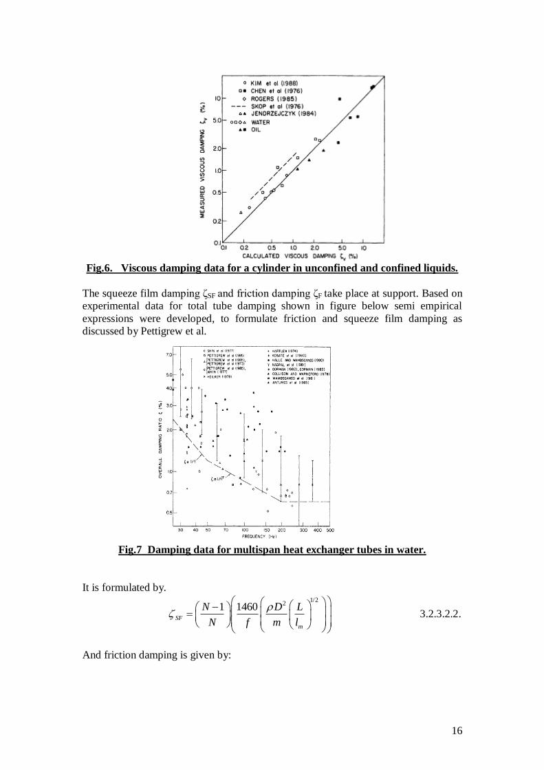
Fig.6. Viscous damping data for a cylinder in unconfined and confined liquids.
The squeeze film damping ζSF and friction damping ζF take place at support. Based on
experimental data for total tube damping shown in figure below semi empirical
expressions were developed, to formulate friction and squeeze film damping as
discussed by Pettigrew et al.
Fig.7 Damping data for multispan heat exchanger tubes in water.
It is formulated by.
1/221 1460
SF
m
N D L
N f m l
3.2.3.2.2.
And friction damping is given by:

17
1/2
10.5F
m
N L
N l
3.2.3.2.3
The total friction is given by
T v SF F 3.2.3.2.4
3.2.3.3. Damping in two phase flow.
The total damping ratio, ζT of a multispan heat exchanger tube in two-phase flow
comprises support damping, ζS viscous damping, ζV and two-phase damping, ζTP
T S V TP 3.2.3.3.1.
Depending on the thermal hydraulic conditions the supports may be dry or wet. If the
supports are dry, which is more likely for high heat flux and very high void fraction,
only friction damping takes place. Support damping in this case is analogous to
damping of heat exchanger tubes in gases. Damping due to friction in dry support
may be expressed as eq 2.3.1.1. The above situation is similar to heat exchanger tube
in gas.
When there is liquid between the tube and support, support damping includes
both squeeze film damping, friction damping. The correlation is given by
2
1 14600.5l
S SF F
DN
N f m
3.2.3.3.2
32
2 2 2
1 ( / )2100
(1 ( / ) )8
eTP TPV
e
D DD
m fD D D
3.2.3.3.3
Where νTP is the equivalent two phase kinematic viscosity. There is a two-phase
component of damping in addition to viscous damping. Two-phase damping is
strongly dependent on void fraction, fluid properties and flow regimes, directly
related to confinement and to the ratio of hydrodynamic mass over tube mass, and
weakly related to frequency, mass flux or flow velocity, and tube bundle
configuration. A semi-empirical expression was developed from the available
experimental data to formulate the two-phase component of damping, ζTP in percent:
2 3
2 2
1 ( / )4 ( )
[1 ( / ) ]
l eTP g
e
D D Df
m D D
3.2.3.3.4
3.2.4. Dynamic stiffness and support effectiveness
For unfinned tubes, the dynamic stiffness of multispan heat exchanger tubes is simply
the flexural rigidity, EI. For finned tubes, the increase in flexural rigidity due to the
fins is equivalent to an increase in wall thickness equal to 1/4 of the fin width, a at the
root of the fin over the length of the fin. Thus the equivalent stiffness, EIes is found
using the following equation

18
1 1 1
es a b
a b
EI a b EI a b EI
3.2.4.1.
3.3. Vibration excitation mechanisms.
It means that by which mechanism vibration is being generated. Several vibration
excitation mechanisms are normally considered in heat exchanger tube bundles in
cross flow namely (i) fluid elastic instability (ii) Periodic wake shedding (iii) Acoustic
resonance.
3.3.1 Fluid elastic instability.
When a cylinder in an array of cylinders is displaced, the flow field shifts, changing
the fluid forces on the cylinders. These fluid forces can induce instability if the energy
input by the fluid force exceeds the energy expended in damping. The cylinders, or
tubes, generally vibrate in oval orbits. In tube and shell heat exchangers, these
vibrations are called fluid elastic instability. In arrays of power transmission lines, the
vibrations are called wake galloping. Fluid elastic instability is a dominant cause of
tube failure in heat exchangers. Similarly wake galloping instability of power lines is
a major concern in transmission line design. Analysis of fluid elastic instability
requires an accurate theoretical description of the unsteady fluid forces imposed on a
tube in an array of vibration tubes. This very difficult problem has not yet been fully
resolved. In fact, none of the current models are capable of prediction the instability
of an untested heat exchange tube array with better accuracy than the band of data.
However theory does provide insight into the nature of the instability and estimates
for instability when data are not available. Fluidelastic instability is formulated in
terms of a dimensionless flow velocity, Up=fD; and a dimensionless mass-damping
parameter, 2πζm/ρD2
1/2
2
2pU mK
fD D
3.3.1.1
Where f is the tube natural frequency, ρ is the fluid density, m is the tube mass per
unit length and Up is the threshold, or critical, flow velocity for fluid elastic
instability. A fluid elastic instability constant K = 3:0 is recommended for all tube
bundle configurations, the damping ratio ζ is the total damping ratio as defined in the
previous topics as total damping ratios.
3.3.2 Periodic wake shedding
Periodic wake shedding, or vortex shedding, may be a problem when the shedding
frequency coincides with a tube natural frequency. This may lead to resonance and
large vibration amplitudes. Periodic wake shedding resonance may be of concern in
liquid cross flow where the flow is relatively uniform. It is not normally a problem at
the entrance region of steam generators because the flow is very non-uniform and
quite turbulent Turbulence inhibits periodic wake shedding Periodic wake shedding
is generally not a problem in two-phase flow except at very low void fractions
Periodic wake shedding resonance is usually not a problem in gas heat exchangers.
The gas density is usually too low to cause significant periodic forces at flow
velocities close to resonance. Normal flow velocities in gas heat exchangers are
usually much higher than those required for resonance. However, it may be possible

19
in high-pressure components with higher density gas on the shell side. It could also
happen for higher modes of vibration with higher frequencies corresponding to higher
flow velocities. Thus, periodic wake shedding resonance cannot always be ignored in
gas heat exchangers. Generally, there is little information on the magnitude of
periodic wake shedding forces in tube bundles. There is more information on periodic
wake shedding frequencies. However, this information is often contradictory.
Periodic wake shedding is described in terms of a Strouhal number S = fsD/Up; which
formulates the wake shedding frequency, fs; and a fluctuating lift or drag coefficient,
CL; which is used to estimate the periodic forces, Fs; due to wake shedding. Thus,
21
2s L pF C D U 3.3.2.1
3.3.3. Acoustic resonance.
Acoustic resonance may take place in heat exchanger tube bundles when vortex or
periodic wake shedding frequencies coincide with a natural frequency for acoustic
standing waves within a heat exchanger. Such resonance normally causes intense
acoustic noise and often serious tube and baffle damage. Acoustic resonance is
possible in gas heat exchangers with both finned and unfinned tubes. Acoustic
resonance requires two conditions: (i) coincidence of shedding and acoustic
frequency, and (ii) sufficient acoustic energy or sufficiently low acoustic damping to
allow sustained acoustic standing wave resonance. In heat exchanger tube bundles,
acoustic standing waves are generally normal to both the tube axes and the flow
direction. The acoustic standing wave frequencies, fan are defined by
2
an
nCf
W 3.3.3.1
where W is the dimension of the heat exchanger tube bundle cavity in the direction
normal to the flow and the tube axes, n is the mode order and C is the effective speed
of sound which is given by
0
1
CC
3.3.3.2
Where C0 is speed of sound in the working medium. And σ is the solidity ratio. Which
is the ration of the volume occupied by the tubes over the volume of the tube bundle.
For triangular tube bundle,
2
22 3
D
P
3.3.3.3
and for square tube bundle 2
2
D
P
3.3.3.4
Where P is pitch of tubes.
3.4. Vibration response prediction.
Due to the complexity of a multispan heat exchanger tube, a computer code must be
used to predict vibration response accurately and to determine the susceptibility of a
tube to periodic wake shedding resonance and fluidelastic instability. This computer
code must be capable of calculating the mode shapes and natural frequencies for a

20
number of modes at least equal to the number of tube spans. Generally the code will
be in two parts:
(1) The first part will calculate the free vibration tube characteristics such as mode
shapes and natural frequencies, while (2) The second part is a forced vibration
analysis that calculates the tube response to turbulence-induced excitation and
periodic wake shedding, and the fluidelastic instability ratios. A forced vibration
analysis involves the application of the distributed flow velocities and densities. From
a mechanics point-of-view, the tubes are simply multispan beams clamped at the tube
sheet and held at the supports with varying degrees of constraint. To predict tube
response, it is convenient and appropriate to assume that the intermediate supports are
hinged. With this assumption, the analysis is linear and either a finite-element code or
an analytical code can be used. If the tube-to-support clearances are too large, the tube
supports will not be effective and the assumption of hinged supports will not be valid.
Tube-to-support diametral clearances of 0.38mm (0.015 in) or less are typically used
in nuclear heat exchanger design. Effective supports can become ineffective if a heat
exchanger is subjected to significant corrosion or a chemical cleaning technique is
used to clean a fouled unit. The effects of future chemical cleaning and corrosion
should be considered in the vibration response analysis.
3.5. Fretting wear and damage assessment.
The ultimate goal of vibration analyses is to ensure that fretting-wear or fatigue
damage does not occur in heat exchangers. Although a linear analysis does not predict
fretting-wear, significant fretting-wear can be avoided by keeping the predicted
vibration amplitudes below the allowable provided later in this paper. In addition,
fretting-wear damage can be estimated Fretting-wear damage may be assessed using
the following methodology. The total fretting-wear damage over the life of the heat
exchanger must not exceed the allowable tube wall reduction or wear depth, dw.
Fretting-wear damage may be estimated using the following modified Archard
equation
FW NV K W 3.5.1
Where V is the volume fretting-wear rate, KFW is the fretting-wear coefficient, and
NW is the normal work-rate. The work-rate is the available mechanical energy in the
dynamic interaction between tube and support and is an appropriate parameter to
predict fretting-wear damage. The work-rate may be calculated by performing a
nonlinear time domain simulation of a multispan heat exchanger tube vibrating within
its supports. Alternately, the work-rate may be estimated with the following
simplified expression
3 3 2
max16N sW f ml y 3.5.2
Where m is the total mass of tube per unit length, and 2
maxy and f are, respectively, the
maximum mean-square vibration amplitude and the natural frequency of the tube for
the worst mode. The worst mode of a given region is defined as the mode of vibration
that has the highest value for the normal work-rate term WN; in Eq. 5.2 The length l is
that of the span where the vibration amplitude is maximum and ζs is the damping ratio
attributed to the supports.

21
WEAR DEPTH CALCULATION
It may be assumed to be conservative that fretting-wear is taking place continuously
for a total time, Ts corresponding to the life of the component. The total fretting-wear
volume, V is calculated from Eq. 3.5.1
S S FW NV T V T K W 3.5.3
The resulting tube wall wear depth, dw; can be calculated from the wear volume. This
requires the relationship between dw and V. For example, for a tube within a circular
hole or a scalloped bar, it may be assumed that the wear is taking place uniformly
over the thickness L and half the circumference πD of the support. Thus
2
w
Vd
DL 3.5.4
Fretting wear coefficient depends on choice of material and systems corrosion, heat
transfer consideration. Tube and tube-support materials should be chosen to minimize
fretting-wear damage. Similar materials such as Inconel-600 (I600) tubes and I600
supports must be avoided. Incoloy-800 (I800), Inconel-690 (I690) and I600 tubes with
410S, 304L, 316L, 321SS or carbon steel supports are considered acceptable material
combinations from a fretting-wear point of view. The value of fretting wear
coefficient KFW of 20X10-15
m2/N may be used as first approximation for tube and
support of above material.
3.6. Mathematical modeling
In many industrial configurations, mechanical structures such as PWR components
are subjected to complex flows causing possible vibrations and damage and as far as
nuclear security is concerned, it is necessary to prevent wear problems generated by
vibration fatigue. The forces acting on tubes are turbulent forces and fluid elastic
forces. These forces can sometimes be directly measured by transducers but with
direct approaches it is often difficult to stand between the different physical
mechanisms involved when a distributed external loading is considered. On the
contrary, indirect experimental prediction methods have shown their ability to provide
fluid force estimates. Most of them rely on force density analytical models depending
themselves on unknown spectral scaled parameters In order to reduce experiments
and to be able to study many configurations involving complex flow-induced
vibration problems, numerical methods are also considered. Owing to recent
developments incorporated into Computational Fluid Dynamic (CFD) codes,
numerical simulation of flow structure coupling is investigated. In nuclear power
plants heat exchanger tube bundles carrying primary fluid are subjected to cross flows
of secondary fluid. External fluid forces may generate high magnitude vibrations of
tubular structures causing possible dramatic damages in terms of nuclear safety.
Vibrations result from four kinds of fluctuations (i) random fluctuations generated by
turbulence in fluid at large Reynolds numbers; (ii) fluctuations induced by structure
flow motion coupling due to fluid-elastic effects; (iii) resonance with flow periodicity
due to vortex shedding; and (iv) possible acoustic excitation.

22
Fig.8 Lift and drag force effect on a flexible tube belonging to a fixed tube
bundle in cross flow
s
Fig.9 Tube ,damper, spring system for model.
Geometric parameters characterizing a regular tube bundle are the following: tube
external and internal diameters D = De and Di, tube gap or pitch P; tube row angle θ
and tube bundle length L: From a mechanical point of view, the flexible tube motion
is characterized by tube mass mS; tube stiffness Ks; tube damping Cs. The equation of
motion without fluid in tube is given by:
0t tm x Cx K x 3.6.1
Where mt is tube mass, C is external damping if provided, Kt is tube material stiffness.
Or equivalent we can write
22 0t tx x x 3.6.2
Where ωt is tube natural frequency without fluid, ζ is tube damping ratio without
fluid. We can also write that
Kt=mt ωt2
3.6.3
And C=2mtωtζ 3.6.4
Concerning the hydraulics parameters, the flow is supposed to cross-perpendicularly
the tube bundle and the axial component is zero. The flow is totally defined by its
Reynolds number,

23
ReUD
3.6.5
where U = Ugap=[P/(P-D)]UN designates the gap velocity, UN the inlet flow velocity
before crossing the tube bundle and μ the fluid dynamic viscosity. Concerning the
structural motion in the fluid at rest, the apparent mode mass and damping are
affected by added mass effects (represented by mh), by internal fluid mass effects
(represented by mi) and by fluid viscosity (represented by Cv) . The equation of
motion becomes
( ) ( ) 0t h i v sm m m x C C x K x 3.6.6
Where Ks is stiffness of tube and fluid inside tube or system stiffness. Or we can
write
22 0T s sx x x 3.6.7
This is governing free damped vibration. The value of ζT can be obtained from
equation number 3.2.3.2.4 or 3.2.3.3.1 what ever may be the case.
24
CHAPTER4.
OBJECTIVE OF THE PROJECT.
The objective of the project is to analyze the flow induced vibration in heat
exchanger. In many industrial applications, mechanical structures like heat exchanger
tube bundles are subjected to complex flows causing possible vibrations and damage.
Part of fluid forces are coupled with tube motion and the so-called fluidelastic forces
can affect the structure dynamic behavior generating possible instabilities and leading
to possible short term failures through high amplitude vibrations. Most classical fluid
force identification methods rely on structure response experimental measurements
associated with convenient data processes. Owing to recent improvements in
Computational Fluid Dynamics, numerical simulation of flow-induced vibrations is
now practicable for industrial purposes. To understand the flow induced vibration in
heat exchanger tubes, one problem is considered here.
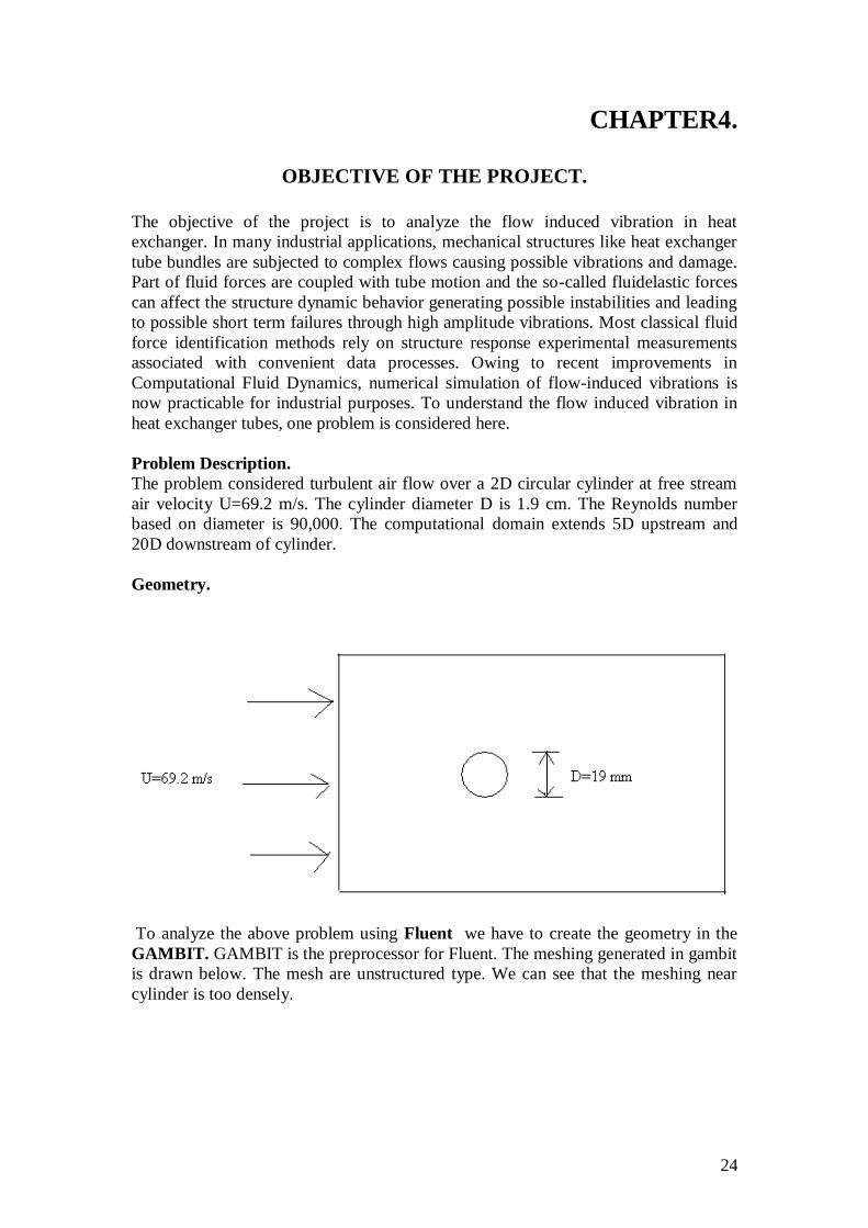
Problem Description.
The problem considered turbulent air flow over a 2D circular cylinder at free stream
air velocity U=69.2 m/s. The cylinder diameter D is 1.9 cm. The Reynolds number
based on diameter is 90,000. The computational domain extends 5D upstream and
20D downstream of cylinder.
Geometry.
To analyze the above problem using Fluent we have to create the geometry in the
GAMBIT. GAMBIT is the preprocessor for Fluent. The meshing generated in gambit
is drawn below. The mesh are unstructured type. We can see that the meshing near
cylinder is too densely.

25
The grid near the cylinder wall is shown below in zoom mode.
We solve the problem with standard k-ε turbulent model. Our aim is to find sound
intensity due to vibration and the Strouhal number which is used in calculation of tube
natural frequency. The static pressure contour is shown below in the cylinder grid.

26
The velocity contour is shown below with maximum of 108 m/s.
The lift coefficient and drag coefficient are plotted in the figure below.
The drag and lift convergence plot as time advances is given below.

27
28
REFERANCES:
1. Cross flow induced vibration of heat exchanger tube banks. By S.S. Chen. p.p.
Nuclear Engineering and Design 47 (1978) 67-86.
2. Vibration analysis of shell-and-tube heat exchangers an overview—Part 1: Flow,
damping, fluidelastic instability. By M.J. Pettigrew, C.E. Taylor. p.p. Journal of
Fluids and Structures 18 (2003) 469–483.
3. Vibration analysis of shell-and-tube heat exchangers: an overview—Part 2:
vibration response, fretting-wear, guidelines. By M.J. Pettigrew, C.E. Taylor. p.p.
Journal of Fluids and Structures 18 (2003) 485–500.
4. Some aspects of heat exchanger tube damping in two phase mixtures. By M. J.
Pettigrew and G. D. Knowles. p.p. Journal of Fluids and Structures (1997) 11,
929–945.
5. Vibration damping of heat exchanger tubes in liquids: Effect of support
parameters. By M.J. Pettigrew, B.S. Kim, J.H. Tromp. p.p. Journal of fluids and
structures (1988)2, 593-614.
6. Flow induced vibration analysis of conical rings used for heat transfer
enhancement in heat exchanger. By Kenan Yakut, Bayram Sahin. p.p. Applied
energy 78 (2004) 273-288.
7. Velocity distribution and vibration excitation in tube bundle heat exchangers. By
Ulrich Mohr, Horst Gelbe. Int. p.p. Journal of thermal science 39(200), 414-421.
8. Methods of numerical study of tube bundle vibration in cross flows. By
E.Longatte, Z. Bendjeddou, M. Souli. p.p. Journal of fluids and structures
18(2003) 513-528.
9. ―Flow induced vibration of circular cylindrical structures‖ (1986) By S.S.Chen,
Hemispherical publication company. Washington.
10. ―Flow induced vibration‖ (1994). By Robert D. Blevins. Krieger publication
company. Florida.
11. ―Flow induced vibration: an engineering guide.‖(1994) Naudascher and Donald
Rockwell. A.A.Balkema publishing company. Netherlands.