vibration behaviour of external payload on rotorcraft
TRANSCRIPT

Vibration Behaviour of
External Payload on Rotorcraft
Schmid David
RUAG Switzerland Ltd
Division Aviation
Torino, 23.04.2013
03.05.2013 RUAG Aviation 2
Content
About RUAG
ISSYS Pod Purpose and Structure
Project Goal
Dynamic Model
Vibration Tests
Comparison of Test and Simulation
03.05.2013 RUAG Aviation 3
RUAG Holding
03.05.2013 RUAG Aviation 4
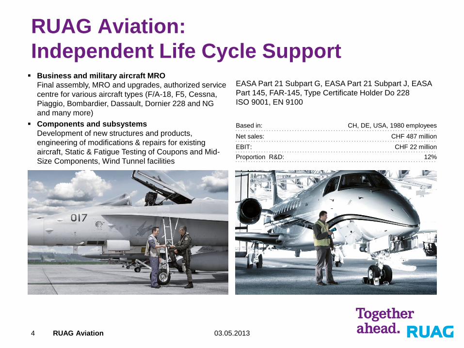
RUAG Aviation:
Independent Life Cycle Support Business and military aircraft MRO
Final assembly, MRO and upgrades, authorized service
centre for various aircraft types (F/A-18, F5, Cessna,
Piaggio, Bombardier, Dassault, Dornier 228 and NG
and many more)
Components and subsystems
Development of new structures and products,
engineering of modifications & repairs for existing
aircraft, Static & Fatigue Testing of Coupons and Mid-
Size Components, Wind Tunnel facilities
EASA Part 21 Subpart G, EASA Part 21 Subpart J, EASA
Part 145, FAR-145, Type Certificate Holder Do 228
ISO 9001, EN 9100
Based in: CH, DE, USA, 1980 employees
Net sales: CHF 487 million
EBIT: CHF 22 million
Proportion R&D: 12%

03.05.2013 RUAG Aviation 5
ISSYS Pod
Self Protection System against guided missiles integrated
into a mobile pod
Pod is attached to the aircraft with an interface adapter
customized for each aircraft type
Interchangeable between aircraft in a short time by ground
personnel
Lower cost of pod versus fully integrated system
Pod system remains the same for all helicopter types, only
interface adapter needs to be redesigned
03.05.2013 RUAG Aviation 6
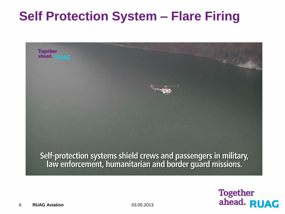
Self Protection System – Flare Firing
03.05.2013 RUAG Aviation 7
ISSYS Pod
03.05.2013 RUAG Aviation 8
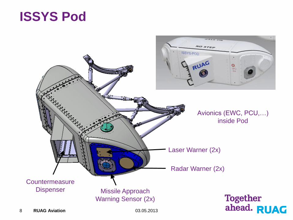
ISSYS Pod
Missile Approach
Warning Sensor (2x)
Radar Warner (2x)
Laser Warner (2x)
Countermeasure
Dispenser
Avionics (EWC, PCU,…)
inside Pod
03.05.2013 RUAG Aviation 9
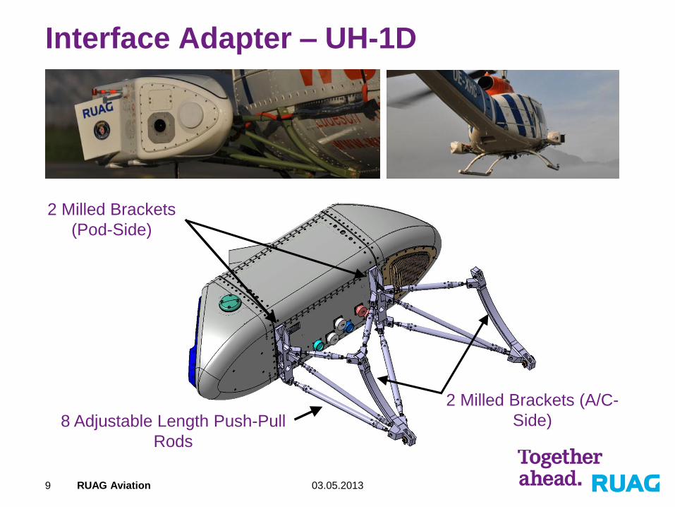
Interface Adapter – UH-1D
2 Milled Brackets
(Pod-Side)
2 Milled Brackets (A/C-
Side) 8 Adjustable Length Push-Pull
Rods
03.05.2013 RUAG Aviation 10
Project Goal
Develop an analysis model to accurately predict eigenfrequencies of
system for new interface adapters and different pod configurations
Challenges:
System non-linearity due to non-linear force-deformation curve of struts
and freeplay between struts and other structure
Short engineering cycle – no time for large engineering tests
Conventional FE analysis (static & eigenmodes) not adequate
Large amount of design constraints & requirements
Solution:
Use MotionView / MotionSolve to simulate vibration behaviour of
system

03.05.2013 RUAG Aviation 11
Design Constraints & Requirements
UH-1D Interface Adapter
Pod position must be adjustable in all 6 degrees of
freedom within certain range
Lightweight (max total weight of LH & RH adapter is 7kg)
Pod position far aft and outboard relative to the hardpoint
positions due to passenger sliding door
Large tolerances of A/C hardpoint positions (absolute and
relative)
Adapter – Pod system must avoid main rotor frequency
bands

03.05.2013 RUAG Aviation 12
Design Constraints – Frequency Bands
03.05.2013 RUAG Aviation 13
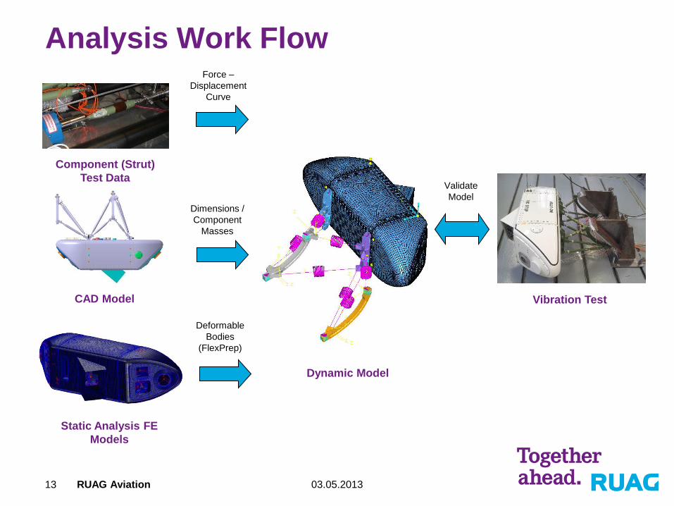
Analysis Work Flow
Component (Strut)
Test Data
Static Analysis FE
Models
CAD Model
Dynamic Model
Vibration Test
Dimensions /
Component
Masses
Force –
Displacement
Curve
Deformable
Bodies
(FlexPrep)
Validate
Model
03.05.2013 RUAG Aviation 14
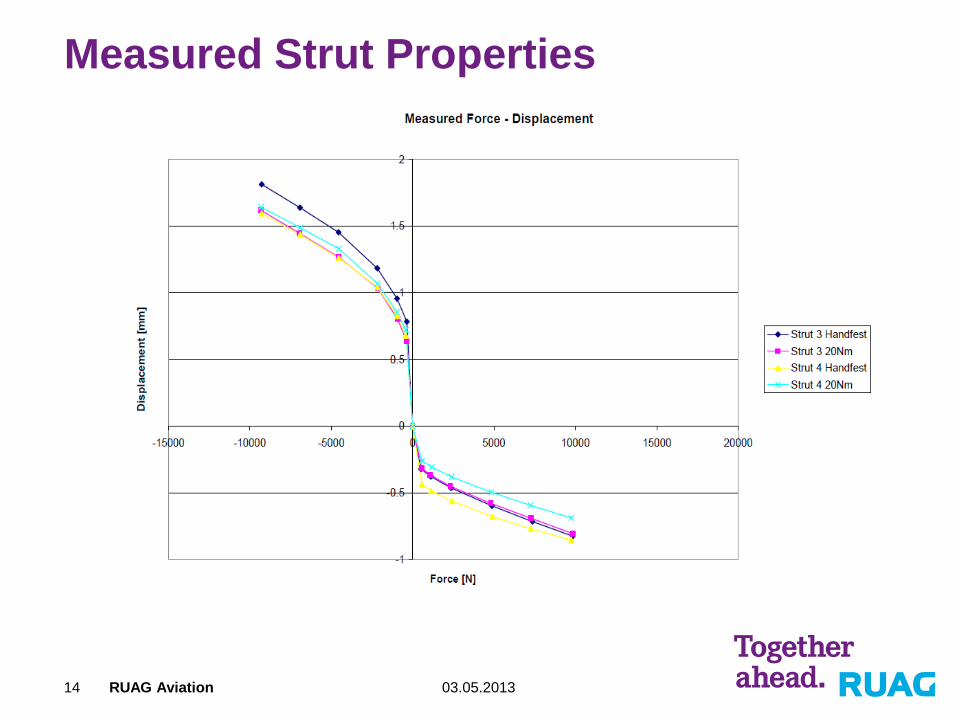
Measured Strut Properties
03.05.2013 RUAG Aviation 15
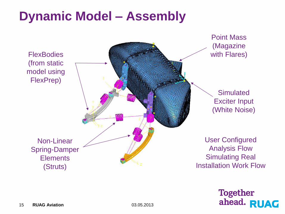
Dynamic Model – Assembly
Non-Linear
Spring-Damper
Elements
(Struts)
FlexBodies
(from static
model using
FlexPrep)
Point Mass
(Magazine
with Flares)
User Configured
Analysis Flow
Simulating Real
Installation Work Flow
Simulated
Exciter Input
(White Noise)
03.05.2013 RUAG Aviation 16
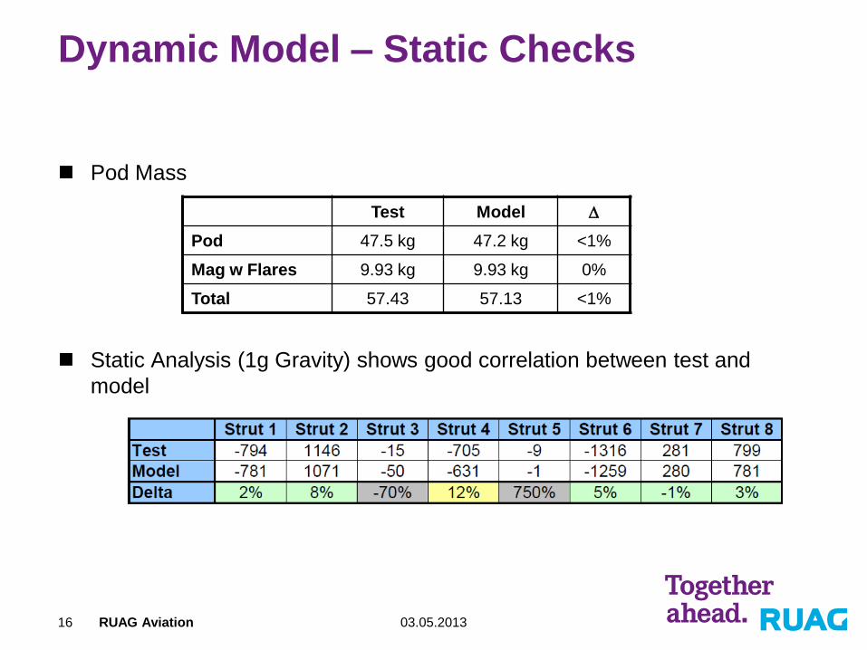
Dynamic Model – Static Checks
Pod Mass
Static Analysis (1g Gravity) shows good correlation between test and
model
Test Model D
Pod 47.5 kg 47.2 kg <1%
Mag w Flares 9.93 kg 9.93 kg 0%
Total 57.43 57.13 <1%

03.05.2013 RUAG Aviation 17
Vibration Tests
Strain Gage Time History Data
(1 configuration only)
Frequency Response

03.05.2013 RUAG Aviation 18
Sample Result: Z - Axis – Full Magazine
Sensor: Envelope Z-Axis
Configuration: CIDAS 100 Light LH
Full Magazine (36 Standard Flares)
03.05.2013 RUAG Aviation 19
Summary
First two modes predicted accurately without model tuning
(D<5%)
Third mode prediction less accurate (D~15%)
Model is easy to set-up and modify
Model not yet ready for standalone prediction, still some
tests needed for simulation of new interface adapter
designs, but helps tremendously during design phase

03.05.2013 RUAG Aviation 20
Thank you for your attention!
20