vico modeling guideline for revit...
TRANSCRIPT
Revit modeling guideline for Vico Office use
1
RevitModelingGuideline
January1
Revit modeling guideline for Vico Office use
2
TableofContents
Complex foundation elements .................................................................................................................................. 3
Steel elements and reference lines ........................................................................................................................... 4
Architectural walls ..................................................................................................................................................... 5
Basic walls with complex geometry ...................................................................................................................... 5
Slanted walls ............................................................................................................................................................. 6
Curtain walls with basic curtain panels ..................................................................................................................... 6
Wall sweeps (and fascia, gutters) ............................................................................................................................. 9
Monolithic stairs ...................................................................................................................................................... 10
Structural Trusses .................................................................................................................................................... 12
Caseworks ............................................................................................................................................................... 13
Revit rooms ............................................................................................................................................................. 13
Complex structural ramps ....................................................................................................................................... 15
Sloped steel bracing ................................................................................................................................................ 17
See Calculation rules in Vico Office Help: ........................................................................................................... 18
Revit modeling guideline for Vico Office use
3
The goal of this document is to provide guidelines for creating 3D construction models, which allow users to fully
utilize the capabilities of Vico Office. The document is NOT a Revit user guide and it shares best practices for
developing construction caliber quantities with a 3D model or with modifying data in Vico Office.
Complexfoundationelements
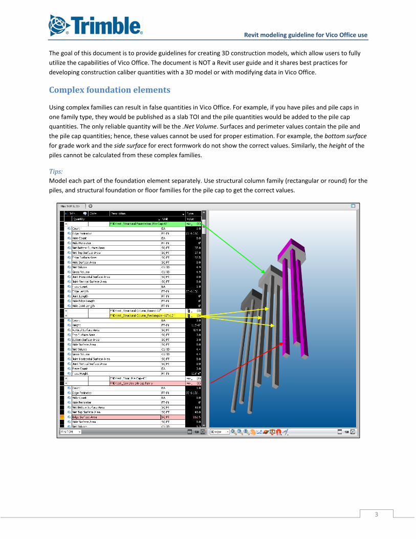
Using complex families can result in false quantities in Vico Office. For example, if you have piles and pile caps in
one family type, they would be published as a slab TOI and the pile quantities would be added to the pile cap
quantities. The only reliable quantity will be the .Net Volume. Surfaces and perimeter values contain the pile and
the pile cap quantities; hence, these values cannot be used for proper estimation. For example, the bottom surface
for grade work and the side surface for erect formwork do not show the correct values. Similarly, the height of the
piles cannot be calculated from these complex families.
Tips:Model each part of the foundation element separately. Use structural column family (rectangular or round) for the
piles, and structural foundation or floor families for the pile cap to get the correct values.
Revit modeling guideline for Vico Office use
4
Steelelementsandreferencelines
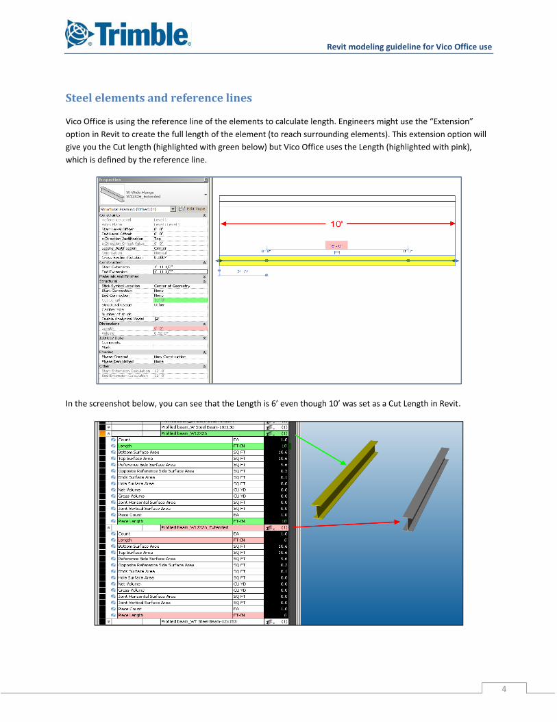
Vico Office is using the reference line of the elements to calculate length. Engineers might use the “Extension”
option in Revit to create the full length of the element (to reach surrounding elements). This extension option will
give you the Cut length (highlighted with green below) but Vico Office uses the Length (highlighted with pink),
which is defined by the reference line.
In the screenshot below, you can see that the Length is 6’ even though 10’ was set as a Cut Length in Revit.
Revit modeling guideline for Vico Office use
5
Tips: Model the steel’s reference line along the longest distance that is required between other structural elements. If it
causes clashes, pull back the end extension of the beam but not the reference line.
Architecturalwalls
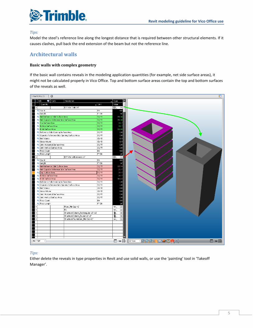
Basicwallswithcomplexgeometry
If the basic wall contains reveals in the modeling application quantities (for example, net side surface areas), it
might not be calculated properly in Vico Office. Top and bottom surface areas contain the top and bottom surfaces
of the reveals as well.
Tips:Either delete the reveals in type properties in Revit and use solid walls, or use the ‘painting’ tool in ‘Takeoff
Manager’.
Revit modeling guideline for Vico Office use
6
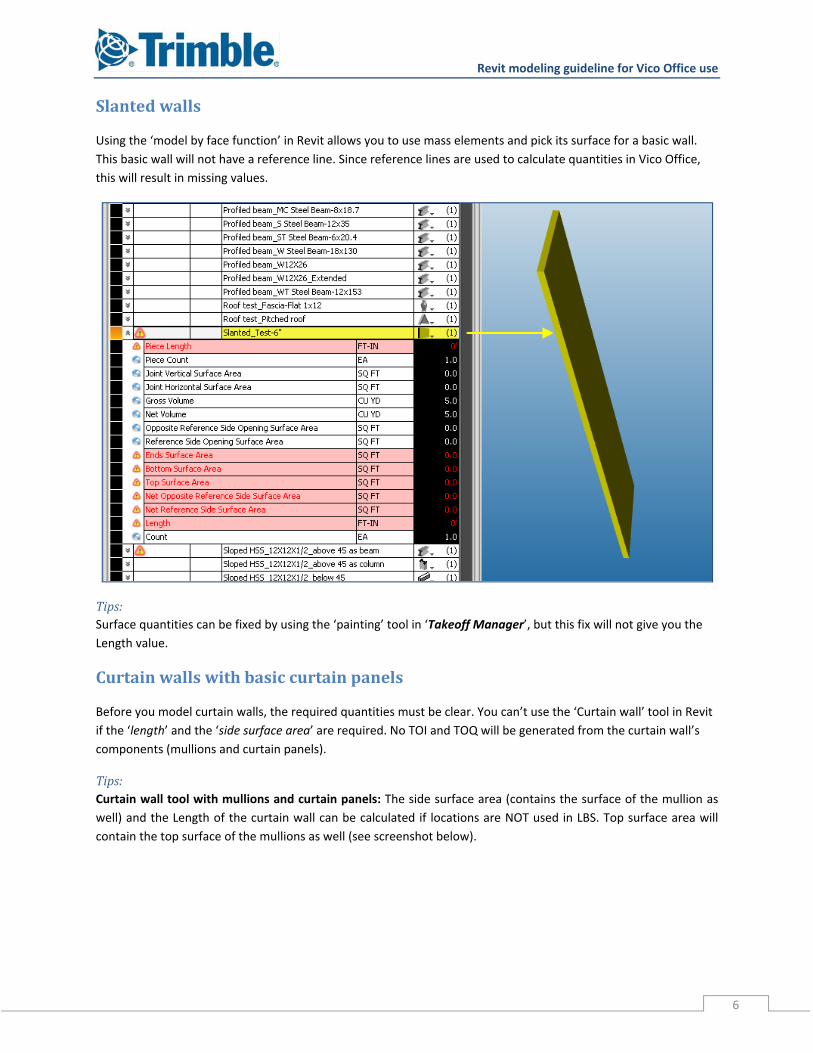
Slantedwalls
Using the ‘model by face function’ in Revit allows you to use mass elements and pick its surface for a basic wall.
This basic wall will not have a reference line. Since reference lines are used to calculate quantities in Vico Office,
this will result in missing values.
Tips:Surface quantities can be fixed by using the ‘painting’ tool in ‘Takeoff Manager’, but this fix will not give you the
Length value.
Curtainwallswithbasiccurtainpanels
Before you model curtain walls, the required quantities must be clear. You can’t use the ‘Curtain wall’ tool in Revit
if the ‘length’ and the ‘side surface area’ are required. No TOI and TOQ will be generated from the curtain wall’s
components (mullions and curtain panels).
Tips: Curtain wall tool with mullions and curtain panels: The side surface area (contains the surface of the mullion as
well) and the Length of the curtain wall can be calculated if locations are NOT used in LBS. Top surface area will
contain the top surface of the mullions as well (see screenshot below).

Revit modeling guideline for Vico Office use
7
Curtain wall tool with mullions and basic walls as curtain panels: The curtain panels can be replaced with basic
walls in Revit. In this case, two ‘Takeoff Items’ will be generated: one for the curtain wall and one for the walls that
are replacing the curtain panels. The remaining part (in this case the mullions) is recognized as the curtain wall. Its
side surface area can be used for mullions. This way of modeling gives you the proper count and surface of the
panels.
Revit modeling guideline for Vico Office use
8
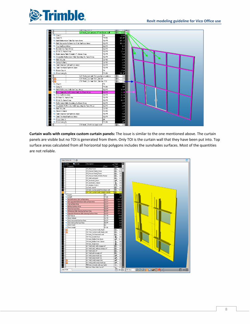
Curtain walls with complex custom curtain panels: The issue is similar to the one mentioned above. The curtain
panels are visible but no TOI is generated from them. Only TOI is the curtain wall that they have been put into. Top
surface areas calculated from all horizontal top polygons includes the sunshades surfaces. Most of the quantities
are not reliable.
Revit modeling guideline for Vico Office use
9
Tips:It is recommended to model the curtain
panel from basic walls, and then create a
group of them. After that, the model groups
can be copied as requested. It’s enough to
edit one group ‐‐ changes will be applied to
all groups. On the screenshots below you
can see an example. There are two model
groups, a bottom and a top panel. Each
model group contains the following: basic
walls (one layer for framing and another for
cover); windows; beams and columns for
sunshades.
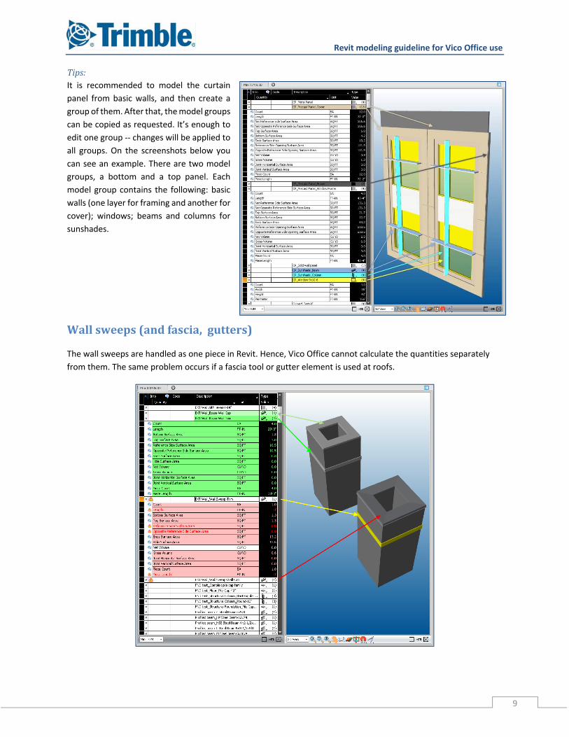
Wallsweeps(andfascia,gutters)
The wall sweeps are handled as one piece in Revit. Hence, Vico Office cannot calculate the quantities separately
from them. The same problem occurs if a fascia tool or gutter element is used at roofs.
Revit modeling guideline for Vico Office use
10
Tips:It’s recommended to model these elements separately with, for example, a basic rectangular beam tool or with
Revit schedule.
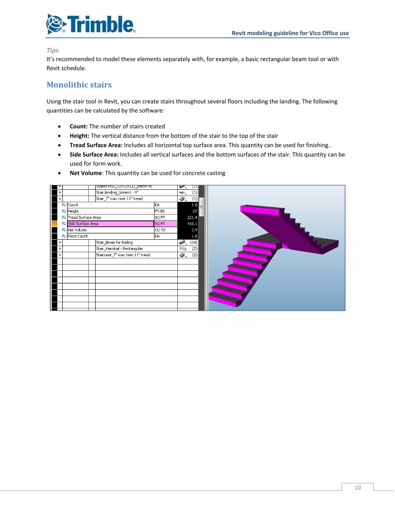
Monolithicstairs
Using the stair tool in Revit, you can create stairs throughout several floors including the landing. The following
quantities can be calculated by the software:
Count: The number of stairs created
Height: The vertical distance from the bottom of the stair to the top of the stair
Tread Surface Area: Includes all horizontal top surface area. This quantity can be used for finishing..
Side Surface Area: Includes all vertical surfaces and the bottom surfaces of the stair. This quantity can be
used for form work.
Net Volume: This quantity can be used for concrete casting
Revit modeling guideline for Vico Office use
11
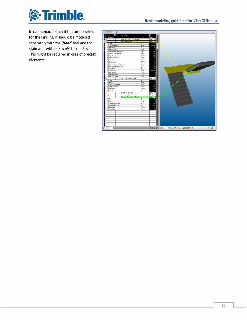
In case separate quantities are required
for the landing, it should be modeled
separately with the ‘floor’ tool and the
staircases with the ‘stair’ tool in Revit.
This might be required in case of precast
elements.
Revit modeling guideline for Vico Office use
12
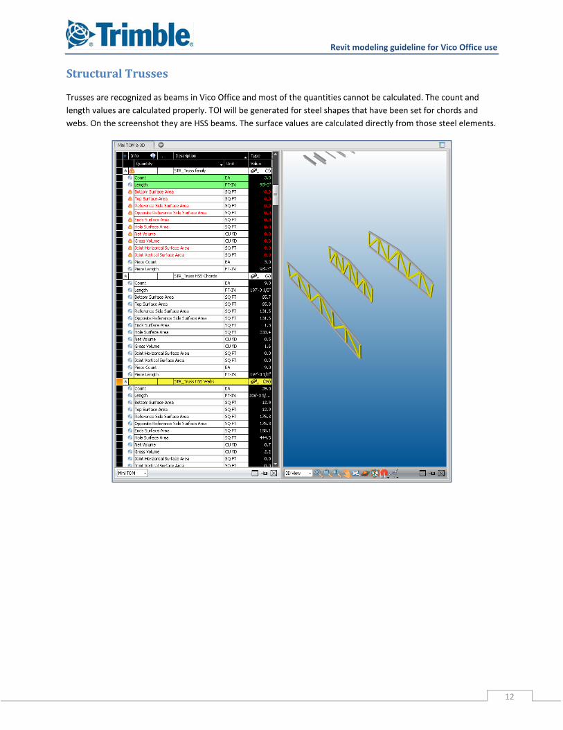
StructuralTrusses
Trusses are recognized as beams in Vico Office and most of the quantities cannot be calculated. The count and
length values are calculated properly. TOI will be generated for steel shapes that have been set for chords and
webs. On the screenshot they are HSS beams. The surface values are calculated directly from those steel elements.
Revit modeling guideline for Vico Office use
13
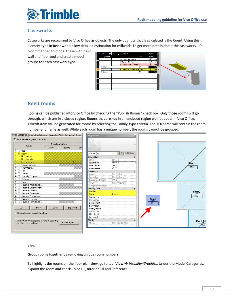
Caseworks
Caseworks are recognized by Vico Office as objects. The only quantity that is calculated is the Count. Using this
element type in Revit won’t allow detailed estimation for millwork. To get more details about the caseworks, it’s
recommended to model these with basic
wall and floor tool and create model
groups for each casework type.
Revitrooms
Rooms can be published into Vico Office by checking the “Publish Rooms” check box. Only those rooms will go
through, which are in a closed region. Rooms that are not in an enclosed region won’t appear in Vico Office.
Takeoff item will be generated for rooms by selecting the Family Type criteria. The TOI name will contain the room
number and name as well. While each room has a unique number, the rooms cannot be grouped.
Tips:
Group rooms together by removing unique room numbers.
To highlight the rooms on the floor plan view, go to tab: View Visibility/Graphics. Under the Model Categories,
expand the room and check Color Fill, Interior Fill and Reference.
Revit modeling guideline for Vico Office use
14
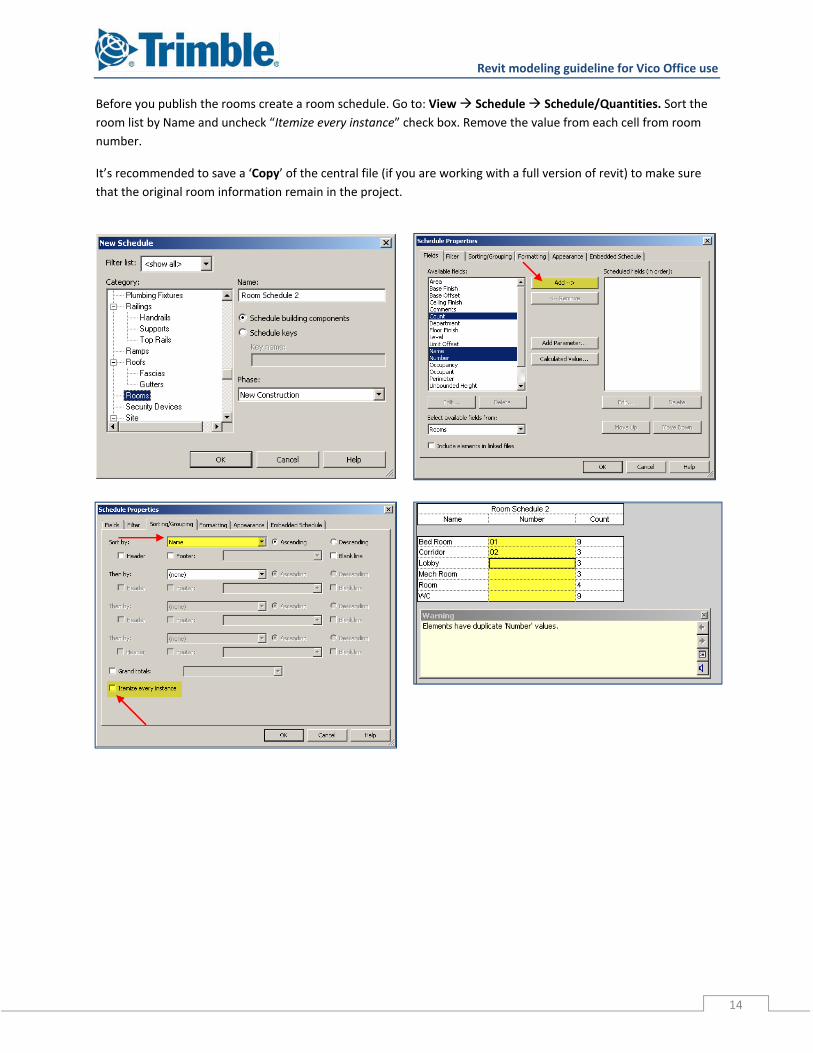
Before you publish the rooms create a room schedule. Go to: View Schedule Schedule/Quantities. Sort the
room list by Name and uncheck “Itemize every instance” check box. Remove the value from each cell from room
number.
It’s recommended to save a ‘Copy’ of the central file (if you are working with a full version of revit) to make sure
that the original room information remain in the project.
Revit modeling guideline for Vico Office use
15
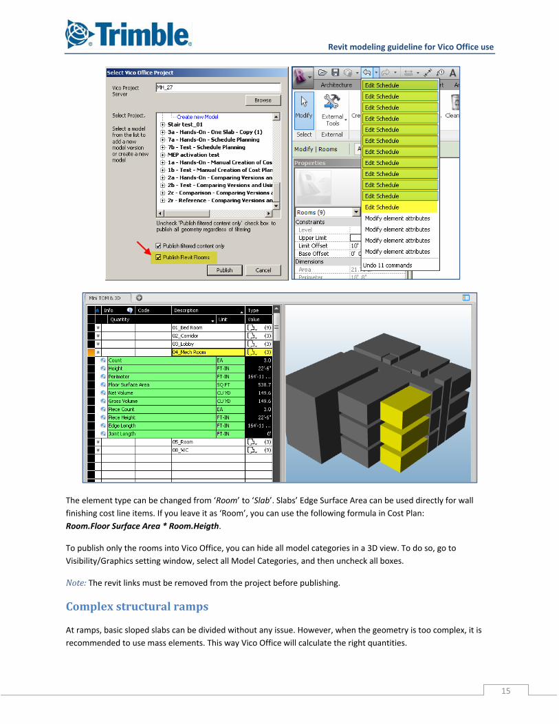
The element type can be changed from ‘Room’ to ‘Slab’. Slabs’ Edge Surface Area can be used directly for wall
finishing cost line items. If you leave it as ‘Room’, you can use the following formula in Cost Plan:
Room.Floor Surface Area * Room.Heigth.
To publish only the rooms into Vico Office, you can hide all model categories in a 3D view. To do so, go to
Visibility/Graphics setting window, select all Model Categories, and then uncheck all boxes.
Note: The revit links must be removed from the project before publishing.
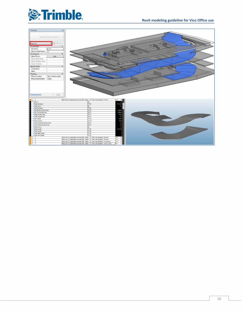
Complexstructuralramps
At ramps, basic sloped slabs can be divided without any issue. However, when the geometry is too complex, it is
recommended to use mass elements. This way Vico Office will calculate the right quantities.
Revit modeling guideline for Vico Office use
16
Revit modeling guideline for Vico Office use
17
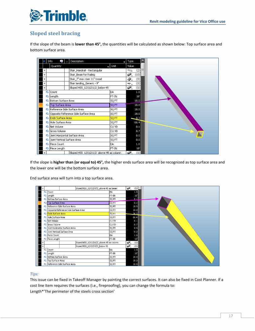
Slopedsteelbracing
If the slope of the beam is lower than 45°, the quantities will be calculated as shown below: Top surface area and
bottom surface area.
If the slope is higher than (or equal to) 45°, the higher ends surface area will be recognized as top surface area and
the lower one will be the bottom surface area.
End surface area will turn into a top surface area.
Tips:This issue can be fixed in Takeoff Manager by painting the correct surfaces. It can also be fixed in Cost Planner. If a
cost line item requires the surfaces (i.e., fireproofing), you can change the formula to:
Length*’The perimeter of the steels cross section’
Revit modeling guideline for Vico Office use
18
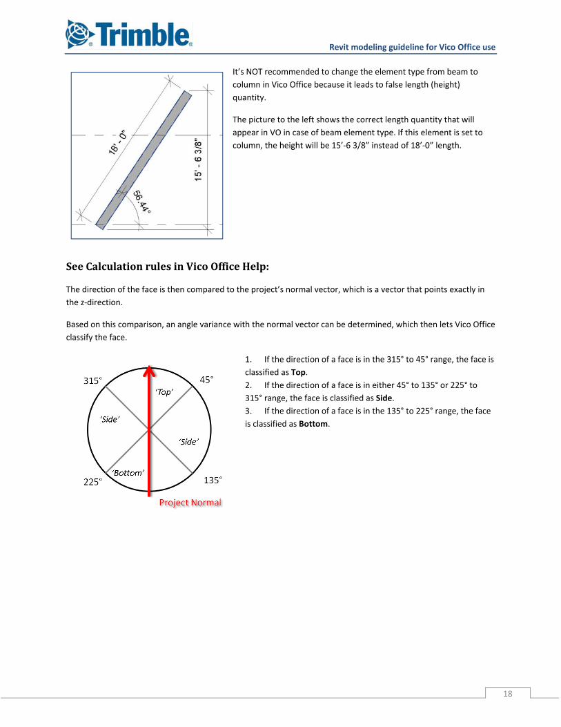
It’s NOT recommended to change the element type from beam to
column in Vico Office because it leads to false length (height)
quantity.
The picture to the left shows the correct length quantity that will
appear in VO in case of beam element type. If this element is set to
column, the height will be 15’‐6 3/8” instead of 18’‐0” length.
SeeCalculationrulesinVicoOfficeHelp:
The direction of the face is then compared to the project’s normal vector, which is a vector that points exactly in
the z‐direction.
Based on this comparison, an angle variance with the normal vector can be determined, which then lets Vico Office
classify the face.
1. If the direction of a face is in the 315° to 45° range, the face is
classified as Top.
2. If the direction of a face is in either 45° to 135° or 225° to
315° range, the face is classified as Side.
3. If the direction of a face is in the 135° to 225° range, the face
is classified as Bottom.