view interpolation from a single view 1. render object 2. convert z-buffer to range image 3....
Post on 20-Dec-2015
222 views
TRANSCRIPT
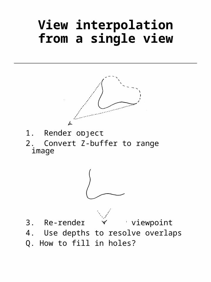
View interpolationfrom a single view
1. Render object2. Convert Z-buffer to range image
3. Re-render from new viewpoint4. Use depths to resolve overlapsQ. How to fill in holes?
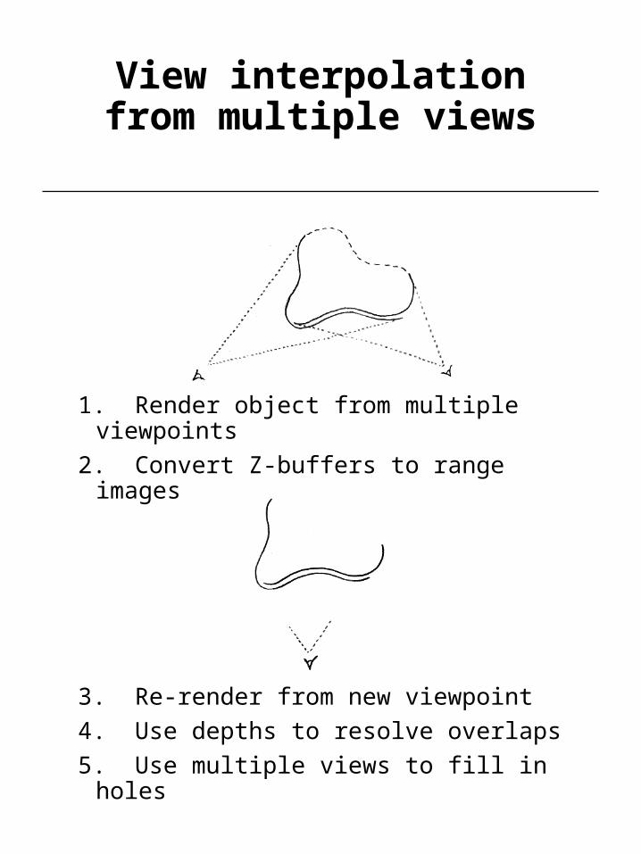
View interpolationfrom multiple views
1. Render object from multiple viewpoints
2. Convert Z-buffers to range images
3. Re-render from new viewpoint
4. Use depths to resolve overlaps
5. Use multiple views to fill in holes
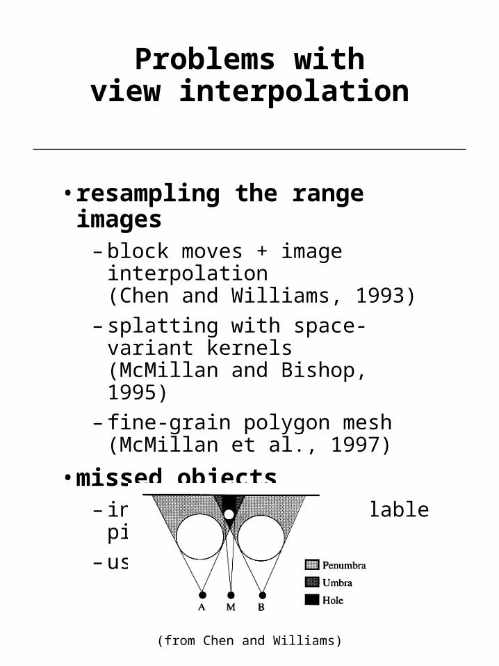
Problems withview interpolation
• resampling the range images– block moves + image interpolation
(Chen and Williams, 1993)
– splatting with space-variant kernels(McMillan and Bishop, 1995)
– fine-grain polygon mesh(McMillan et al., 1997)
• missed objects– interpolate from available pixels
– use more views
(from Chen and Williams)

More problemswith view interpolation
• Obtaining range images is hard!– use synthetic images
(Chen and Williams, 1993)
– epipolar analysis(McMillan and Bishop, 1995)
cylindrical epipolar geometry
epipolar geometry
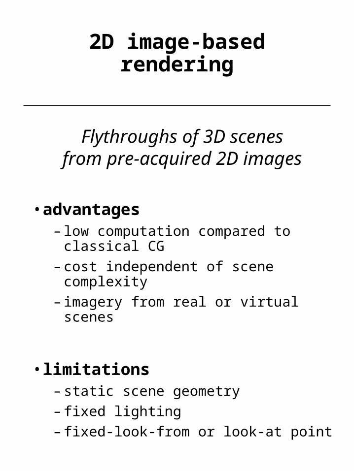
2D image-based rendering
• advantages– low computation compared to classical CG
– cost independent of scene complexity
– imagery from real or virtual scenes
• limitations– static scene geometry
– fixed lighting
– fixed-look-from or look-at point
Flythroughs of 3D scenesfrom pre-acquired 2D images

Apple QuickTime VR
• outward-looking– panoramic views at regularly spaced points
• inward-looking– views at points on the surface of a sphere

A new solution:rebinning old views
• must stay outside convex hull of the object
• like rebinning in computed tomography
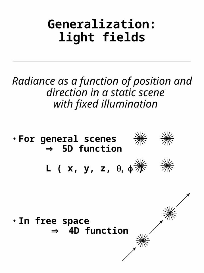
Generalization:light fields
Radiance as a function of position and direction in a static scene
with fixed illumination
• For general scenes5D function
L ( x, y, z, )
• In free space 4D function
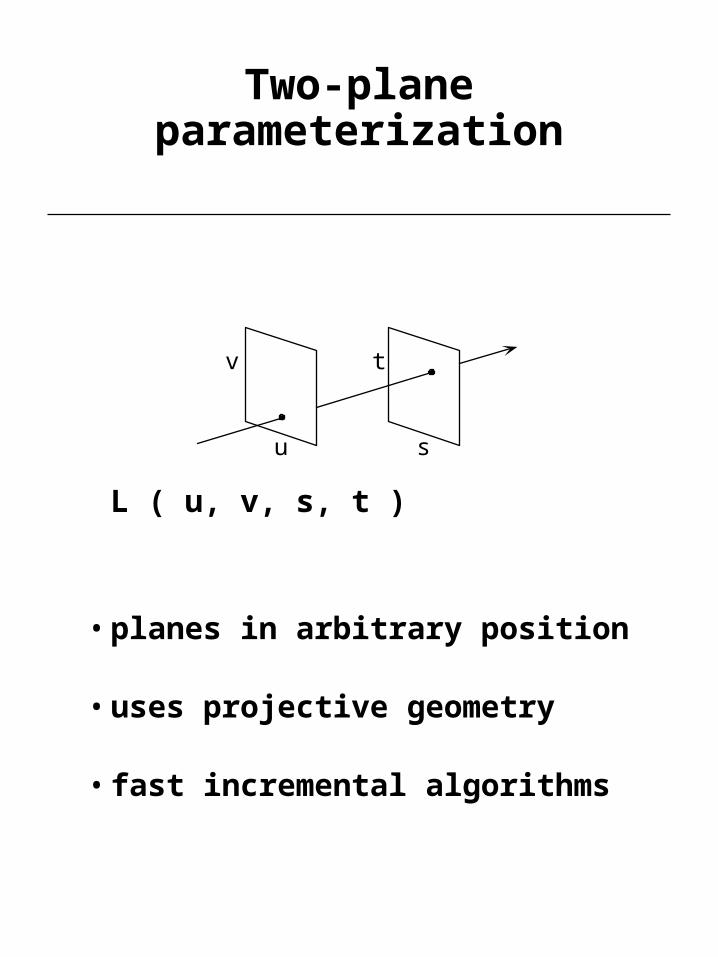
Two-plane parameterization
L ( u, v, s, t )
• planes in arbitrary position
• uses projective geometry
• fast incremental algorithms
u
v
s
t
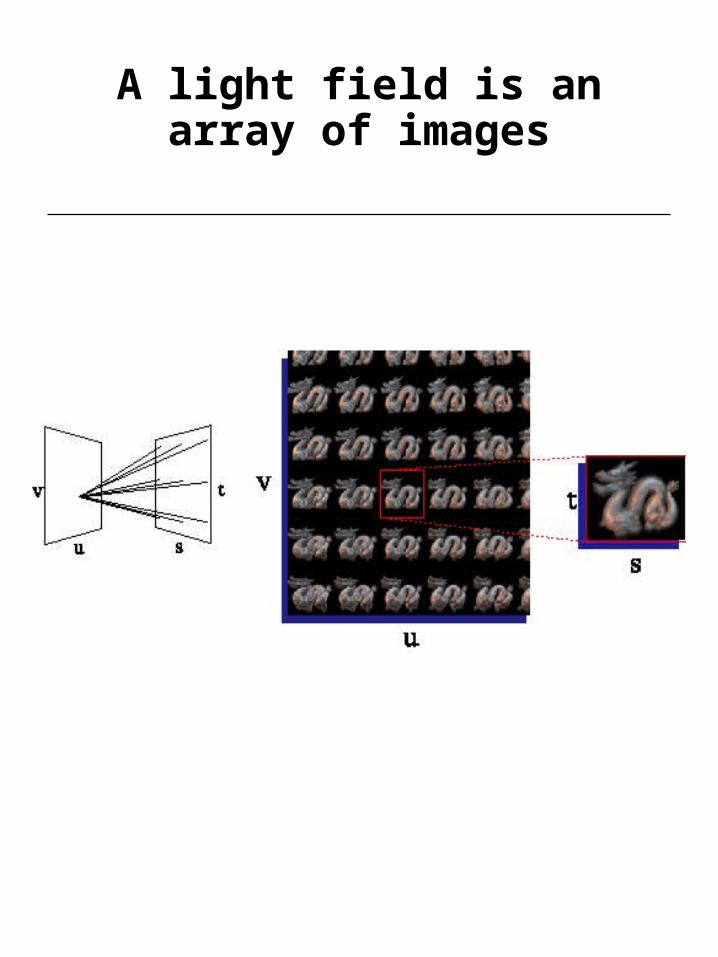
A light field is anarray of images
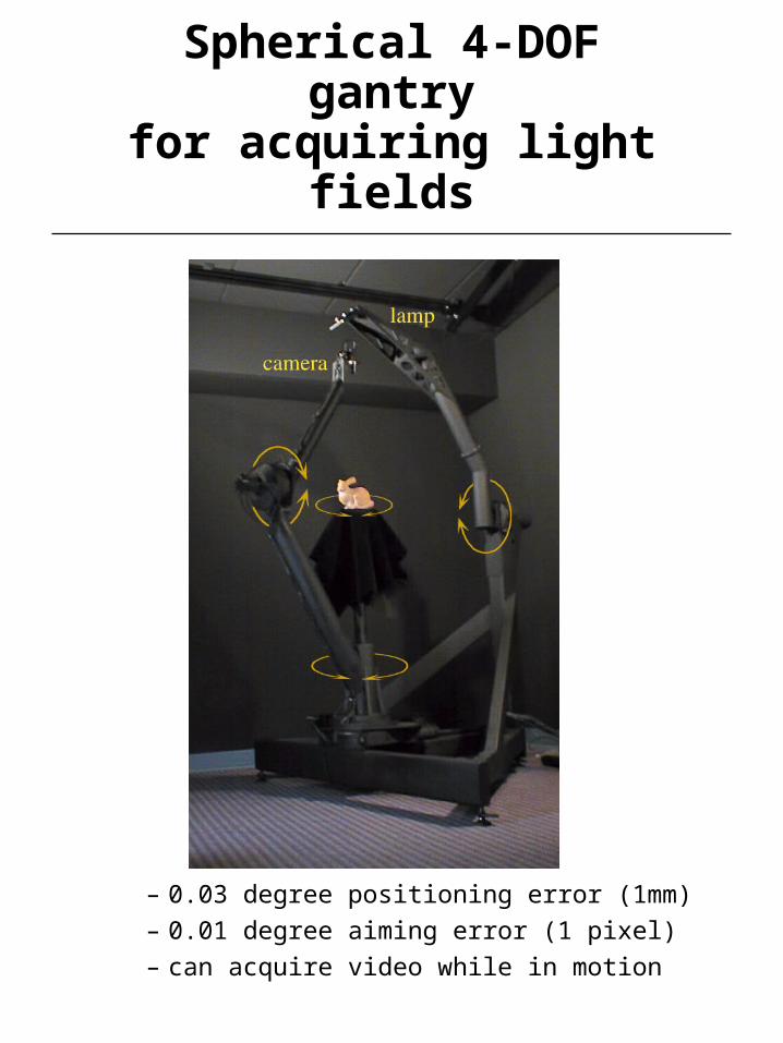
Spherical 4-DOF gantryfor acquiring light fields
– 0.03 degree positioning error (1mm)
– 0.01 degree aiming error (1 pixel)
– can acquire video while in motion
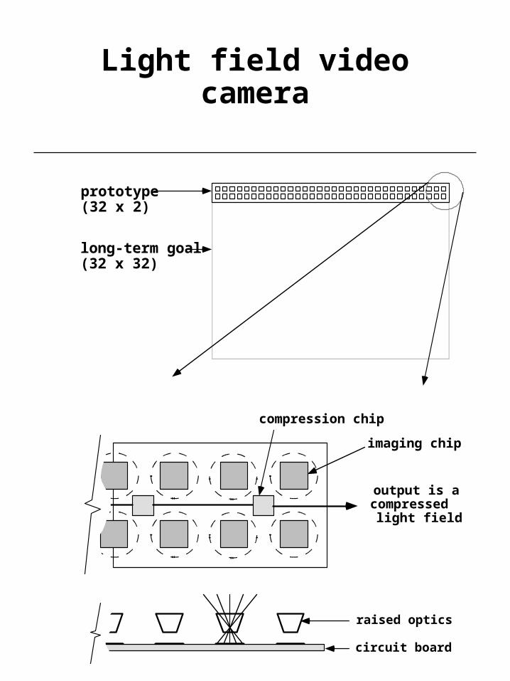
Light field video camera
prototype(32 x 2)
long-term goal(32 x 32)
output is acompressedlight field
imaging chip
compression chip
raised optics
circuit board
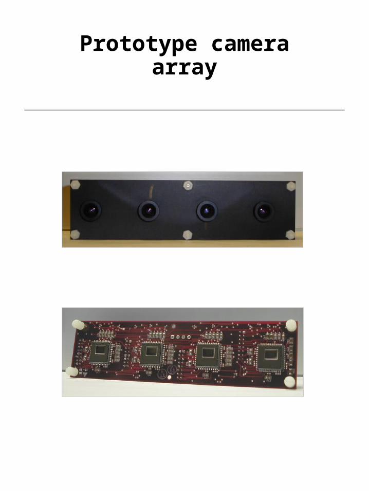
Prototype camera array

Geometry-based versusimage-based rendering
model images
real-time interactive flythrough
conceptual world real world
offlinerendering
imageanalysis
real-timerendering
image-basedrendering
modelconstruction
imageacquisition

Another view:the geometry-based/image-based
rendering continuum
• enhanced video– panoramic
– multiresolution
– multiple viewpoints
– video + alpha + Z
• image-based rendering– QTVR
– light fields
• 3D modelsmore
knowledge of scene
less knowledge
of scene