viewing - katie.cs.mtech.edu
TRANSCRIPT

VIEWING

OUTLINE
• Positioning a Camera
• Projections
• Orthogonal
• Perspective

COMPUTER VIEWING
3
• There are three aspects of the viewing process, all of which are implemented in the
pipeline,
• Positioning the camera
• Setting the model-view matrix
• Selecting a lens
• Setting the projection matrix
• Clipping
• Setting the view volume
THE OPENGL CAMERA
4
• In OpenGL, initially the object and camera frames are the same
• Default model-view matrix is an identity
• The camera is located at origin and points in the negative z
direction
• OpenGL also specifies a default view volume that is a cube with
sides of length 2 centered at the origin
• Default projection matrix is an identity

MOVING THE CAMERA FRAME
5
• If we want to visualize object with both positive and
negative z values we can either
• Move the camera in the positive z direction
• Translate the camera frame
• Move the objects in the negative z direction
• Translate the world frame
• Both of these views are equivalent and are determined by the model-view matrix
• Want a translation (Translate(0.0,0.0,-d);)
• d > 0

MOVING CAMERA BACK FROM ORIGIN
6
default frames frames after translation by –d
d > 0

A LOOKAT FUNCTION
7
• Given:
• the location of the camera/eye (a point)
• the location of the target to look at (a point)
• a suitable “up” direction in the world space, usually y
axis (a vector)
• Create the transformation matrix to “move” the
camera/world so it reflects this configuration

CAMERA COORDINATE SYSTEM

THE LOOKAT MATRIX
A LOOKAT METHOD IN JAVA/JOGL (1/2)
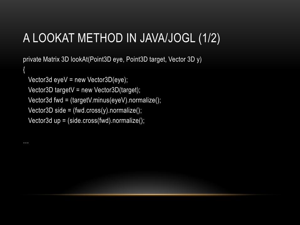
private Matrix 3D lookAt(Point3D eye, Point3D target, Vector 3D y)
{
Vector3d eyeV = new Vector3D(eye);
Vector3D targetV = new Vector3D(target);
Vector3d fwd = (targetV.minus(eyeV).normalize();
Vector3D side = (fwd.cross(y).normalize();
Vector3d up = (side.cross(fwd).normalize();
…

A LOOKAT METHOD IN JAVA/JOGL (2/2)
…
Matrix3D look = new Matrix3D();
look.setElementAt(0, 0, side.getX());
look.setElementAt(1, 0, up.getX);
look.setElementAt(2, 0, -fwd.getX());
look.setElementAt(3, 0, 0.0f);
look.setElementAt(0, 1, side.getY());
look.setElementAt(1, 1, up.getY());
look.setElementAt(2, 1, -fwd.getY());
look.setElementAt(3, 1, 0.0f);
look.setElementAt(0, 2, side.getZ());
look.setElementAt(1, 2, up.getZ());
look.setElementAt(2, 2, -fwd.getZ());
look.setElementAt(3, 2, 0.0f);
look.setElementAt(0, 3, side.dot(eyeV.mult(-1)));
look.setElementAt(1, 3, up.dot(eyeV.mult(-1)));
look.setElementAt(2, 3, (fwd.mult(-1).dot(eveV.mult(-1)));
look.setElementAt(3, 3, 1.0f);
return(look);
}

CLASSICAL PROJECTIONS
12

PLANAR GEOMETRIC PROJECTIONS
13
• Standard projections project onto a plane
• Projectors are lines that either
• converge at a center of projection
• are parallel
• Such projections preserve lines
• but not necessarily angles
• Nonplanar projections are needed for applications such as map construction

MAIN CLASSES OF PLANAR GEOMETRICAL
PROJECTIONS
14
• Perspective: determined by Center of Projection (COP) (in our diagrams, the “eye”)
– More natural, simulates what our eyes or a camera sees
• Parallel: determined by Direction of Projection (DOP) (projectors are parallel—do not converge to “eye” or COP).
– Used in engineering and architecture for measurement purposes
• In general, a projection is determined by where you place the projection plane relative to principal axes of object (relative angle and position), and what angle the projectors make with the projection plane
TAXONOMY OF PLANAR GEOMETRIC
PROJECTIONS
1
5
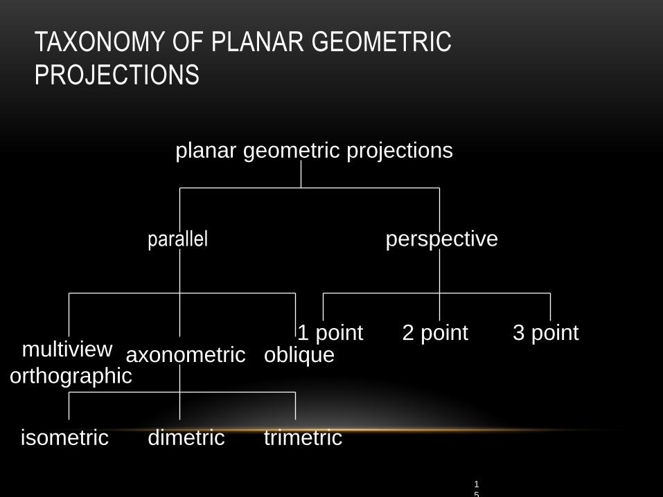
parallel perspective
axonometric multiview
orthographic oblique
isometric dimetric trimetric
2 point 1 point 3 point
planar geometric projections

ORTHOGONAL VIEWING
16
near and far measured from camera

EARLY FORMS OF PROJECTION
17
• Ancient Egyptian Art:
– Multiple Viewpoints
– Parallel Projection
– Tomb of Nefertari, Thebes (19th Dyn,
~1270 BC), Queen led by Isis. Mural
• Note how the depiction of the body
implies a front view but the feet and
head imply side view (early cubism)

PERSPECTIVE
18

EARLY ATTEMPTS AT PERSPECTIVE
19
• In art, an attempt to represent 3D space more realistically
• Earlier works invoke a sense of 3D space but not systematically
• Lines converge, but no single vanishing point
Giotto
Franciscan Rule
Approved
Assisi, Upper
Basilica
c.1295-1300

MORE REALISTIC PERSPECTIVE

ORTHOGRAPHIC PROJECTION
21
Projectors are orthogonal to projection surface

MULTIVIEW ORTHOGRAPHIC (PARALLEL)
22
• Used for:
– engineering drawings of machines,
machine parts
– working architectural drawings
• Pros:
– accurate measurement possible
– all views are at same scale
• Cons:
– does not provide “realistic” view or
sense of 3D form
• Usually need multiple views to get a
three-dimensional feeling for object

ADVANTAGES AND DISADVANTAGES
23
• Preserves both distances and angles
• Shapes preserved
• Can be used for measurements
• Building plans
• Manuals
• Cannot see what object really looks like because many surfaces hidden from view
• Often we add the isometric

AXONOMETRIC PROJECTIONS
24
Allow projection plane to move relative to object
classify by how many angles of
a corner of a projected cube are
the same
none: trimetric
two: dimetric
three: isometric
q 1
q 3 q 2

TYPES OF AXONOMETRIC
PROJECTIONS
25
AXONOMETRIC (PARALLEL)
26
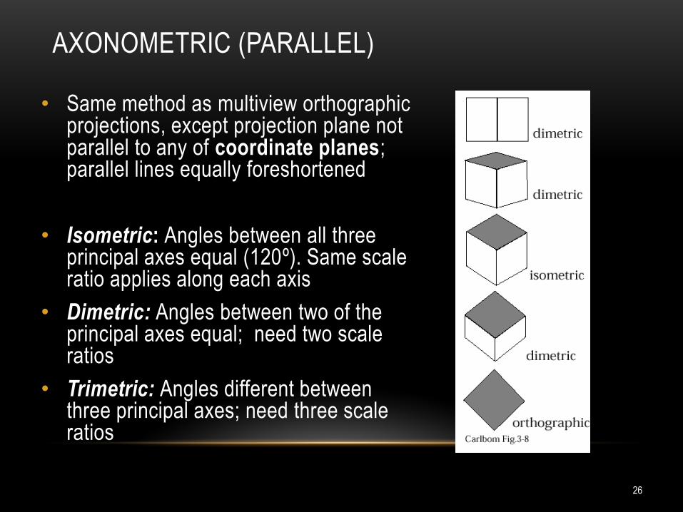
• Same method as multiview orthographic projections, except projection plane not parallel to any of coordinate planes; parallel lines equally foreshortened
• Isometric: Angles between all three principal axes equal (120º). Same scale ratio applies along each axis
• Dimetric: Angles between two of the principal axes equal; need two scale ratios
• Trimetric: Angles different between three principal axes; need three scale ratios

ISOMETRIC PROJECTION
27
• Used for:
• catalogue illustrations
• patent office records
• furniture design
• structural design
• 3d Modeling in real time
• Pros:
• don’t need multiple views
• illustrates 3D nature of object
• measurements can be made to scale along principal axes
• Cons:
• lack of foreshortening creates distorted appearance
• more useful for rectangular than curved shapes
Construction of an isometric projection: projection plane cuts each principal axis by 45°

A DESK IN PARALLEL
28
multiview orthographic
cavalier cabinet


AXONOMETRIC PROJECTION IN GAMES
30
• Video games have been using
isometric projection for ages.
• It all started in 1982 with Q*Bert and
Zaxxon which were made possible
by advances in raster graphics
hardware
• Still in use today when you want to
see things in distance as well as
things close up (e.g. strategy,
simulation games)
• SimCity
• StarCraft

31
ORTHOGONAL MATRIX
• Two steps
• Move center to origin
T(-(left+right)/2, -(bottom+top)/2,(near+far)/2))
• Scale to have sides of length 2
S(2/(left-right),2/(top-bottom),2/(near-far))
1000
200
02
0
002
nearfar
nearfar
farnear
bottomtop
bottomtop
bottomtop
leftright
leftright
leftright
P = ST =

ORTHOGRAPHIC PROJECTION MATRIX

PERSPECTIVE PROJECTION
33
Projectors coverge at center of projection

PERSPECTIVE PROJECTIONS
34
• Used for:
• fine art
• Human visual system…
• Pros:
• gives a realistic view and feeling for 3D form of object
• Cons:
• does not preserve shape of object or scale (except
where object intersects projection plane)
• Different from a parallel projection because
• parallel lines not parallel to the projection plane
converge
• size of object is diminished with distance
• foreshortening is not uniform
• Two understandings: Vanishing Point and View Point
If we were viewing this
scene using parallel
projection, the tracks would
not converge

VANISHING POINTS
35
• Parallel lines (not parallel to the projection plan) on the
object converge at a single point in the projection (the
vanishing point)
• Drawing simple perspectives by hand uses these
vanishing point(s)
vanishing point

VANISHING POINTS
36
• Lines extending from edges converge to common vanishing point(s)
• For right-angled forms whose face normals are perpendicular to the x, y,
z coordinate axes, number of vanishing points = number of principal
coordinate axes intersected by projection plane
Three Point Perspective (z, x, and y-axis vanishing points)
Two Point Perspective (z, and x-axis vanishing points)
One Point Perspective (z-axis vanishing point)
z

THREE-POINT PERSPECTIVE
37
• No principal face parallel to projection plane
• Three vanishing points for cube

TWO-POINT PERSPECTIVE
38
• One principal direction parallel to projection plane
• Two vanishing points for cube

ONE-POINT PERSPECTIVE
39
• One principal face parallel to projection plane
• One vanishing point for cube

ADVANTAGES AND DISADVANTAGES
40
• Objects further from viewer are projected smaller than
the same sized objects closer to the viewer (diminution) – Looks realistic
• Equal distances along a line are not projected into equal
distances (nonuniform foreshortening)
• Angles preserved only in planes parallel to the projection
plane
• More difficult to construct by hand than parallel
projections (but not more difficult by computer)

PERSPECTIVE PROJECTION
• Need four parameters:
• aspect ratio: width/height of near and far clipping planes
• field of view: vertical angle of the viewing space
• projection/near clipping plane
• far clipping plane
• This forms the view volume, or frustum

PERSPECTIVE PROJECTION MATRIX FORMATION

PERSPECTIVE PROJECTION MATRIX


45
NOTES • We stay in four-dimensional homogeneous coordinates through both the modelview and
projection transformations
• Both these transformations are nonsingular
• Default to identity matrices (orthogonal view)
• Normalization lets us clip against simple cube regardless of type of projection
• Delay final projection until end
• Important for hidden-surface removal to retain depth information as long as possible

SUMMARY
• Positioning a Camera
• Projections
• Orthogonal
• Perspective
46