virtual design of automotive electronic networks - vector · klaus-jürgen amsler ......
TRANSCRIPT

COVER STORY Virtual Design
Automotive Electronics I/2004, special issue of ATZ, MTZ and Automotive Engineering Partners, Vieweg Verlag (Wiesbaden, Germany), p. 2-4
The possibilities of virtual design are highlighted in this article of Vector Informatik GmbHand Vector Consulting GmbH using the example of an automobile ECU network. Here, allelements of the network and the total system are modeled and simulated with the help ofsuitable CA(S)E tools. Only after successful conclusion of the simulation does the succes-sive implementation on real control units occur. Design certainty – especially in the earlyphase of development – is thus improved significantly.
By Joachim Fetzer, Dieter Lederer, Matthias Wernicke and
Klaus-Jürgen Amsler
Virtuelles Design von
Kfz-Elektronik-Netzwerken
– Von der Funktion zur
Steuergeräte-Software
You will find the figures mentioned in this article in the German issue of Automotive Electronics beginning on page 8.
Virtual Design of Automotive ElectronicNetworks From Function to ECU Software

Technical Article
Virtual Design of Automotive Electronic Networks 1/16
Virtual Design of Automotive Electronic Networks
From Function to ECU Software
The possibilities of virtual design are highlighted in this
article of Vector Informatik GmbH and Vector Consulting
GmbH using the example of an automobile ECU network. Here,
all elements of the network and the total system are mod-
eled and simulated with the help of suitable CA(S)E tools.
Only after successful conclusion of the simulation does the
successive implementation on real control units occur. De-
sign certainty - especially in the early phase of develop-
ment - is thus improved significantly.
1 Introduction
Of all the automotive innovations in the future, it is
forecast that 90% will be based on electronics development,
and 80% of that amount will be based on software develop-
ment[1]. In retrospect, this estimate takes the growth in
recent years of electronics content in the vehicle as its
basis. Microprocessors were introduced for engine control,
then used in chassis systems such as ABS and ESP and after-
wards in the body, e.g. for air conditioning or vehicle
access systems. Today telematics and multimedia applica-
tions are in the center of interest, and the replacement of
mechanically actuated components with electrically actuated
ones (X-by-wire) will be widespread in the near future[2].
Accordingly, the transformation that has occurred over the
last two decades in the automotive industry from mechani-
cally oriented companies to electronically or software ori-
ented companies will be further accelerated.
Technical Article
Virtual Design of Automotive Electronic Networks 2/16
This also becomes apparent when considering the growing
complexity of vehicle networks. Since the introduction of
the CAN protocol in production vehicles in 1989, when three
ECUs were implemented, the number of ECUs has increased to
more than 70 ECUs. This was accompanied by an increasing
degree of distribution of more and more complex functions.
Initially only components that worked autonomously, e.g.
engine or gear management ECUs, were connected in a net-
work. Today the diverse functions are distributed over many
ECUs. This development will continue to accelerate in the
future, as increasing demand for comfort and reliability of
a vehicle will join the demand for reduced emissions and
fuel consumption. Thus the perception of a vehicle is in-
creasingly determined by its software. For successful inno-
vations, the ability of developing software in an inexpen-
sive and fast way while maintaining high quality is there-
fore an essential prerequisite.
Furthermore, the number of vehicle variants has risen sig-
nificantly in recent years. All car manufacturers plan on
further increasing this variety, cutting the development
time for new models to about 36 months and reducing costs
drastically.
This trend represents a significant challenge for the prod-
uct creation process of software-based systems, which con-
sists of the engineering and management processes � espe-
cially for the development of vehicle electronic networks.
The present article outlines a scenario for mastering the
engineering challenges of vehicle electronic networks.
Questions arising from mastering the management process are
not discussed here; see[3][4][5].
Technical Article
Virtual Design of Automotive Electronic Networks 3/16
2 Challenges for the Engineering of Vehicle Electronic Net-
works
Challenges for engineering of vehicle electronic network
are found in the following areas.
• Due to packaging problems and hardware costs a satu-
ration effect can be expected for the number of ECUs
in vehicles. In view of increasing functionality this
means an increase in distributing functions over a
limited or even decreasing number of ECUs in vehicle
electronic networks, Figure 1 and Figure 2.
• Reuse of functions and related software components
for different types within a model family and across
car lines in order to achieve high quality at low
cost.
• Brand-defining functions will be developed increas-
ingly by OEMs themselves, i.e. suppliers must be able
to provide reliable integration of third party soft-
ware components into their systems.
• Due to the increasing distribution and interaction of
functions, not only a high maturity of each single
function has to be ensured, but also the stability
and reliability of the whole vehicle electronic net-
work.

Technical Article
Virtual Design of Automotive Electronic Networks 4/16
Figure 1: Combination of three functions, which were previously realized on individual control units, on one control unit (3:1 mapping)
Figure 2: Interacting functions for representing a distributed superior function
To meet these challenges it is necessary to follow a struc-
tured approach for engineering vehicle electronic networks.
Technical Article
Virtual Design of Automotive Electronic Networks 5/16
As in the engineering of a single ECU, this approach empha-
sizes the design phase, which provides a reliable basis for
the concrete implementation of the network from an early
stage. The phase is based on a development method for mod-
elling and simulation (for verification and validation) of
vehicle electronic networks and permits the evaluation of
conformance with the requirements, suitability of the net-
work topology and partitioning with respect to the number
of ECUs, gateways, bus load etc.
Though it is also possible to perform the modelling and
simulation by means of a prototype network, obviously only
a purely computer-based, i.e. virtual design can offer the
required efficiency in terms of simple notation, easy modi-
fiability and depth of testing.
3 Virtual Design and Test
3.1 Engineering Process
In the following, the approach for virtual design of a ve-
hicle network as described in section 2 is applied on the
highest logical level. This level corresponds to the OEM
level in the product creation process, Figure 3. The DaV-
inci tool suite is used as support throughout the engineer-
ing process[7][8].

Technical Article
Virtual Design of Automotive Electronic Networks 6/16
Figure 3: Schematic depiction of the development process for an automo-bile network using the V model. Depicted are the OEM and supplier levels.
For reasons of simplicity the cooperation between OEM and
suppliers is not discussed in this article. The interface
between OEM and its suppliers, which is usually described
by a complex n:m relationship, is highly important for an
integrated and efficient engineering process for systems
and software [3][5]. The approach discussed in this article
can be applied in a fractal manner to the whole product
creation process.
The consequent application of the following items is neces-
sary in order to systematically master the design of a ve-
hicle electronic network.
• Structured system and software development process
starting with an analysis of the requirements.
• Top-down design of the whole network and early veri-
fication/validation to ensure that the development �
possibly in a series � of each component (ECU, etc.)

Technical Article
Virtual Design of Automotive Electronic Networks 7/16
by the supplier is carried out on a reliable basis.
This approach can also be applied in a fractal manner
for each single component of the network.
• Bottom-up design to take into account feedback that
may occur during design and implementation of each
component (e.g. additional signal is required).
• Mapping this approach (system and software engineer-
ing process) onto an integrated CA(S)E tool chain
covering design and related tests.
3.2 Analysis of Requirements
During the analysis of requirements, the vehicle functions
for implementation and related test scenarios are deter-
mined [5].
3.3 Design
In the following, the design phase is described in detail.
The approach presented here is a generic one, i.e. it is
generally applicable for control-engineering tasks as well.
Applications of this kind require a time-triggered bus pro-
tocol. Currently the DaVinci tool suite does not support
this protocol yet. Therefore this article concentrates on
to applications in body electronics.
Using the list of functions for implementation as a basis,
each single function has to be decided as to its hardware,
software and mechanics elements. The functions implemented
in software may be further divided into sub functions, re-
sulting in further (sub) software components. The result of
the design phase is a model of the complete network which
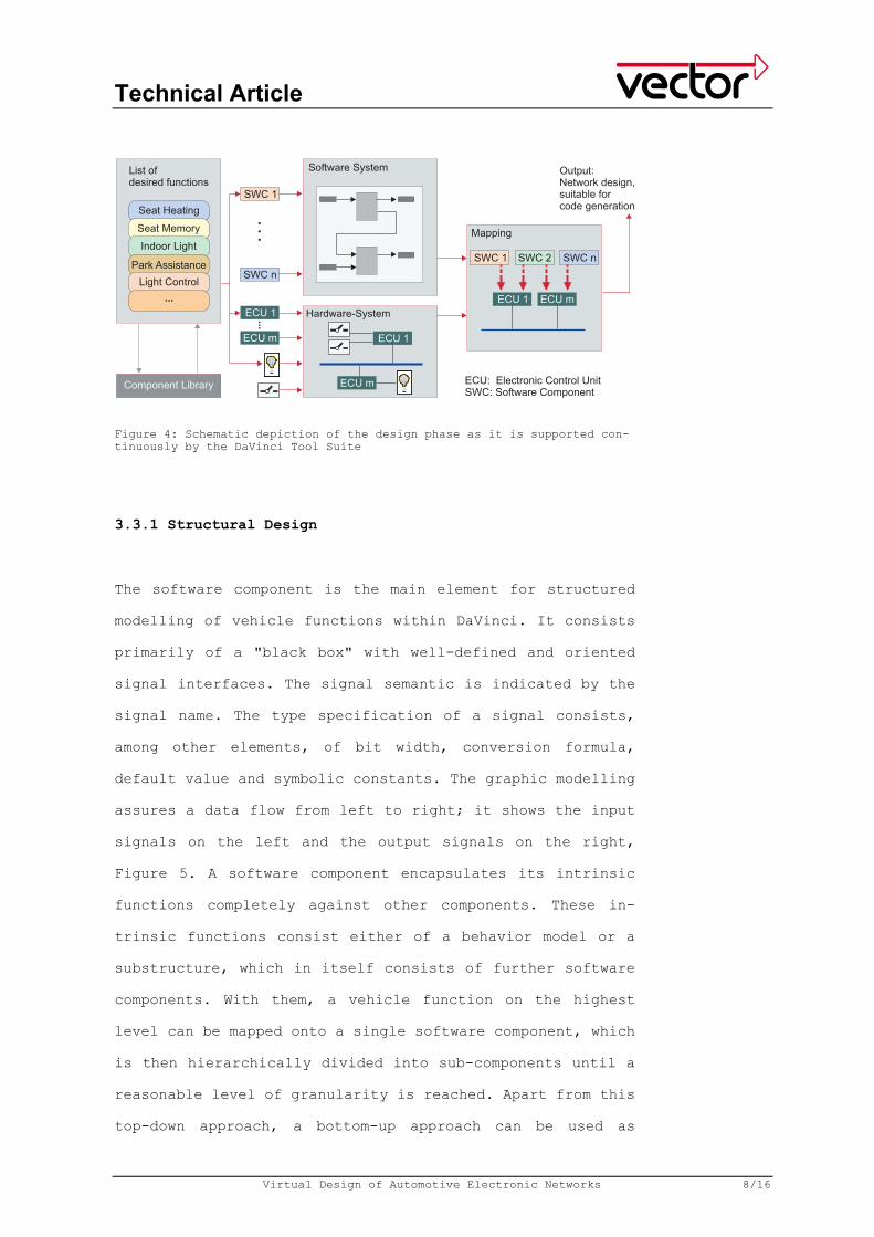
can be simulated after code generation, Figure 4.
Technical Article
Virtual Design of Automotive Electronic Networks 8/16
Figure 4: Schematic depiction of the design phase as it is supported con-tinuously by the DaVinci Tool Suite
3.3.1 Structural Design
The software component is the main element for structured
modelling of vehicle functions within DaVinci. It consists
primarily of a "black box" with well-defined and oriented
signal interfaces. The signal semantic is indicated by the
signal name. The type specification of a signal consists,
among other elements, of bit width, conversion formula,
default value and symbolic constants. The graphic modelling
assures a data flow from left to right; it shows the input
signals on the left and the output signals on the right,
Figure 5. A software component encapsulates its intrinsic
functions completely against other components. These in-
trinsic functions consist either of a behavior model or a
substructure, which in itself consists of further software
components. With them, a vehicle function on the highest
level can be mapped onto a single software component, which
is then hierarchically divided into sub-components until a
reasonable level of granularity is reached. Apart from this
top-down approach, a bottom-up approach can be used as

Technical Article
Virtual Design of Automotive Electronic Networks 9/16
well. In this approach a higher-level software component is
built by using already existing components stored in a com-
ponent library, Figure 4.
Figure 5: Structural design for the software components with the DaVinci Tool Suite
3.3.2 Behavior Description
A software component, which is not further divided, is rep-
resented by a behavior description. This description can be
put into action though one of the following approaches.
• A software component with its signal interfaces is
implemented as a behavior model with equivalent in-
terfaces by using one of the behavior modelling tools
available, e.g. Statemate activity [10] or Simulink
subsystem [9]. These behavior models can be simulated
within these tool environments, i.e. they can be
tested against corresponding test scenarios and

Technical Article
Virtual Design of Automotive Electronic Networks 10/16
evaluated with regard to the expected function. The
code generators of these tools can be modified appro-
priately to ensure consistency of the generated code
with the target interface requested by DaVinci.
• Microcontroller code is implemented directly. Input
or output signals of the component can be accessed
via a macro interface. Direct access to ECU specific
resources (e.g. accessing a specific register) is not
realized.
The behavior model describes the essential task of the
software component, e.g. the execution of a specific algo-
rithm. An important feature of the software component is
its independence from hardware on the one hand and from
other software components on the other hand. For this rea-
son a vehicle function implemented in a software can be
developed and tested as a stand-alone software component
and then stored in a component library, Figure 4.
3.3.3 Functional Integration
In order to realize the desired overall functionality of
the vehicle, all single vehicle functions implemented in
the software are integrated into a software system and con-
nected. So-called DeviceAccessors are used to operate the
still-open signal interfaces, which receive their signals
from sensors and actuators in the real system. A DeviceAc-
cessor is an abstract sensor or actuator and serves as sig-
nal source or signal sink. It allows verification and vali-
dation of the logical function within the overall system.
Technical Article
Virtual Design of Automotive Electronic Networks 11/16
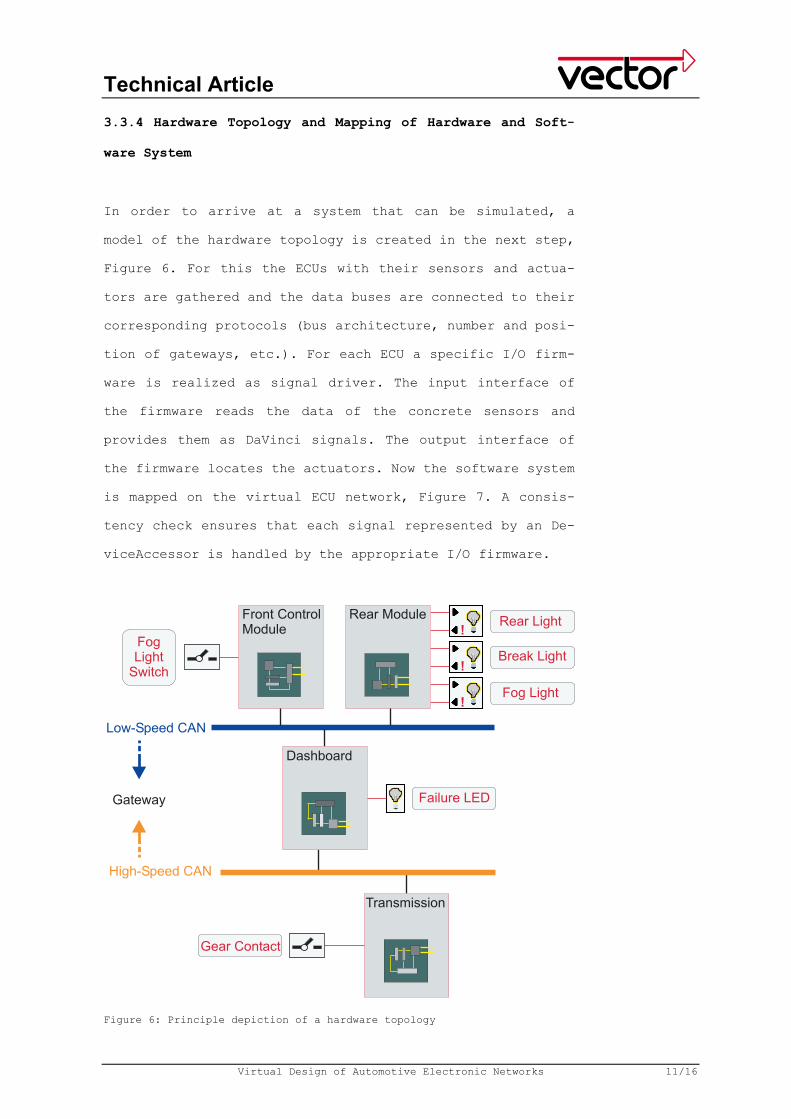
3.3.4 Hardware Topology and Mapping of Hardware and Soft-
ware System
In order to arrive at a system that can be simulated, a
model of the hardware topology is created in the next step,
Figure 6. For this the ECUs with their sensors and actua-
tors are gathered and the data buses are connected to their
corresponding protocols (bus architecture, number and posi-
tion of gateways, etc.). For each ECU a specific I/O firm-
ware is realized as signal driver. The input interface of
the firmware reads the data of the concrete sensors and
provides them as DaVinci signals. The output interface of
the firmware locates the actuators. Now the software system
is mapped on the virtual ECU network, Figure 7. A consis-
tency check ensures that each signal represented by an De-
viceAccessor is handled by the appropriate I/O firmware.
Figure 6: Principle depiction of a hardware topology

Technical Article
Virtual Design of Automotive Electronic Networks 12/16
In the next step the software components are distributed to
the virtual ECUs. This distribution determines which sig-
nals exchanged by the components have to be directed via
the bus and which signals can be exchanged via inter-
process communication. The bus signals are then combined to
bus messages. It is necessary to choose their prioritiza-
tion and transmission type in order to ensure sufficient
speed and safety of the data transmission via the bus. The
communication matrix [11] with its receiving and sending
relationships of the signals and messages can be derived
automatically from this point.
Now a completely modelled design of the network is avail-
able. It can be simulated after code generation. In princi-
ple, the software components can be distributed arbitrarily
to the virtual ECUs. The number of bus signals and the re-
quired ECU resources can be minimized by manual optimiza-
tion of the distribution.
Figure 7: Mapping of the software components on the hardware topology with the DaVinci Tool Suite
Technical Article
Virtual Design of Automotive Electronic Networks 13/16
3.3.5 Runtime Behavior
At this stage, tasks have to be created for each virtual
ECU operating system, and the software components have to
be distributed to these tasks. The runtime behavior of the
system depends on the prioritization of these tasks and the
number and prioritization of bus messages set up for the
transport of signals. Algorithms for an optimal selection
of these parameters are a matter of research work and can
be applied to a DaVinci model. Alternatively these parame-
ters can be manually optimized according to the developers'
experience.
3.3.6 Code Generation and Simulation of the Overall System
After the mapping is completed, the DaVinci model contains
all required information for code generation. The code gen-
eration is carried out on the basis of code elements cre-
ated from the behavior models. These elements, the I/O
firmware and the standard modules [6] are integrated by
automatic code generation. Standard modules like OSEK oper-
ating system, bus drivers, interaction layer etc. are con-
figured automatically. Finally a model of the complete net-
work including its various functions is available, which
can be simulated. The simulation can be executed by apply-
ing a tool like CANoe [12]. Thus the functions can be
evaluated against the test criteria that were defined in
the analysis of requirements. CANoe supports module and
system test on a logical level and in real time. The code
created from the behavior models can be tested with an OSEK
simulation using a PC-based operating environment. Input
and output signals are provided and displayed via a test
Technical Article
Virtual Design of Automotive Electronic Networks 14/16
environment. In this test environment input stimuli can be
created as well.
4 Summary and Conclusion
This article describes a procedure for the complete virtual
design and test of vehicle electronic networks, starting
from the list of functions that need to be realized. In
this process all elements of the network and the complete
system are modelled and simulated using appropriate CA(S)E
tools. The successive implementation of the concrete ECUs
only starts when the simulation has been completed success-
fully, i.e. when it is clear that the network behaves in
accordance with the requirements.
This procedure leads to an significantly increased reli-
ability of the network design at an early stage of develop-
ment. This significantly reduces the risk of incorrect de-
sign decisions which would become visible in later phases
of the development and cause considerable costs.
• Finally an overview of the steps of the virtual de-
sign of vehicle electronic networks:
• Starting point is the list of required functions in-
cluding related test cases.
• Specification of the structure and the interfaces of
functions (structural design).
• Definition of algorithms of the single functions (be-
havior design and modelling).
• Design of the hardware topology (type and number of
ECUs, network protocols, etc.).
• Mapping of the functions (or function parts) on the
ECUs.

Technical Article
Virtual Design of Automotive Electronic Networks 15/16
• Definition of network communication.
• Code generation, simulation and test in regard to the
requirements.
Revised 03/2004 Word count: 2,515 Character count: 16,263
Figure 1: Combination of three functions, which were previously realized on individ-ual control units, on one control unit (3:1 mapping) Figure 2: Interacting functions for representing a distributed superior function Figure 3: Schematic depiction of the development process for an automobile network using the V model. Depicted are the OEM and supplier levels. Figure 4: Schematic depiction of the design phase as it is supported continuously by the DaVinci Tool Suite Figure 5: Structural design for the software components with the DaVinci Tool Suite Figure 6: Principle depiction of a hardware topology Figure 7: Mapping of the software components on the hardware topology with the DaV-inci Tool Suite
All Figures: Vector Informatik GmbH
References
[1] "Networking the way to new systems", International Automobile Manage-ment, 1/2002, pp. 10�13.
[2] "European Automotive Market for X-by-wire Technologies", Frost & Sul-livan, 2001.
[3] Lederer, D.; Heling, G.; Fetzer, J.; Beck, T.: "Der Schlüsssel zum Erfolg. Durchgängige Systems-Engineering-Prozessse � eine vordringli-che Aufgabe", Elektronik Automotive, June 2002, pp. 42�46.
[4] Lederer, D.; Fetzer, J.; Heling, G.; Baumann, G.: "Automotive Systems Engineering � The Solution for Complex Technical Challenges?", Pro-ceedings 5. Internationales Stuttgarter Symposium Kraftfahrwesen und Verbrennunsmotoren, Feb.2003, pp. 593�607.
[5] Lederer, D.; Heling, G.; Fetzer, J.; Beck, T.: "Requirements-Management � Glücksspiel oder systematischer Prozess?", Automotive Engineering Partners, Oct. 2002, pp. 42�46.

Technical Article
Virtual Design of Automotive Electronic Networks 16/16
[6] Erben, M.; Fetzer, J.; Schelling, H.: "Software-Komponenten � Ein neuer Trend in der Automobilelektronik", ATZ/MTZ-Extra, Sep. 2001, pp.74�78.
[7] http://www.vector-informatik.com/davinci/de
[8] Wernicke, M.: "Design mit System", Elektronik Automotive, Dec. 2002, pp. 46�49.
[9] http://www.mathworks.de
[10] http://www.ilogix.com
[11] http://www.vector-informatik.com/candb/de
[12] http://www.vector-informatik.com/canoe/de
Authors: Dr. Joachim Fetzer, Vector Consulting GmbH Tel. +49-711/80670-150, Fax +49-711/80670-444, E-Mail: [email protected] Dr. Dieter Lederer, Vector Consulting GmbH Tel. +49-711/80670-157, Fax +49-711/80670-444, E-Mail: [email protected] Dr. Klaus-Jürgen Amsler, Vector Consulting GmbH Tel. +49-711/80670-284, Fax +49-711/80670-444, E-Mail: [email protected] Matthias Wernicke, Vector Informatik GmbH Tel. +49-711/80670-466, Fax +49-711/80670-111, E-Mail: [email protected] Vector Informatik GmbH Ingersheimer Str. 24 D-70499 Stuttgart www.vector-informatik.com Editorial contact person: Holger Heit Tel. +49-711/80670-567, Fax. +49-711/80670-555, E-mail: [email protected]