virtusurv revit tutorial: creating a new window family · virtusurv revit tutorial: creating a new...
TRANSCRIPT
VirtuSurv Revit Tutorial: Creating a new Window Family
Software used: Revit Architecture 2015, VirtuSurv with Revit Link 15.0
Let’s start Please load the sample project from the VirtuSurv web site and open it, if you have not done so
already. You can find it under following web link: http://download.kubit.de/VirtuSurv/Examples/.
You may also start VirtuSurv and hit the icon in the Welcome screen to access this website.
Download the EXAMPLE02_KUBIT_HOUSE_FIVESCANS.ZIP file. Save it to your computer and then
decompress it.
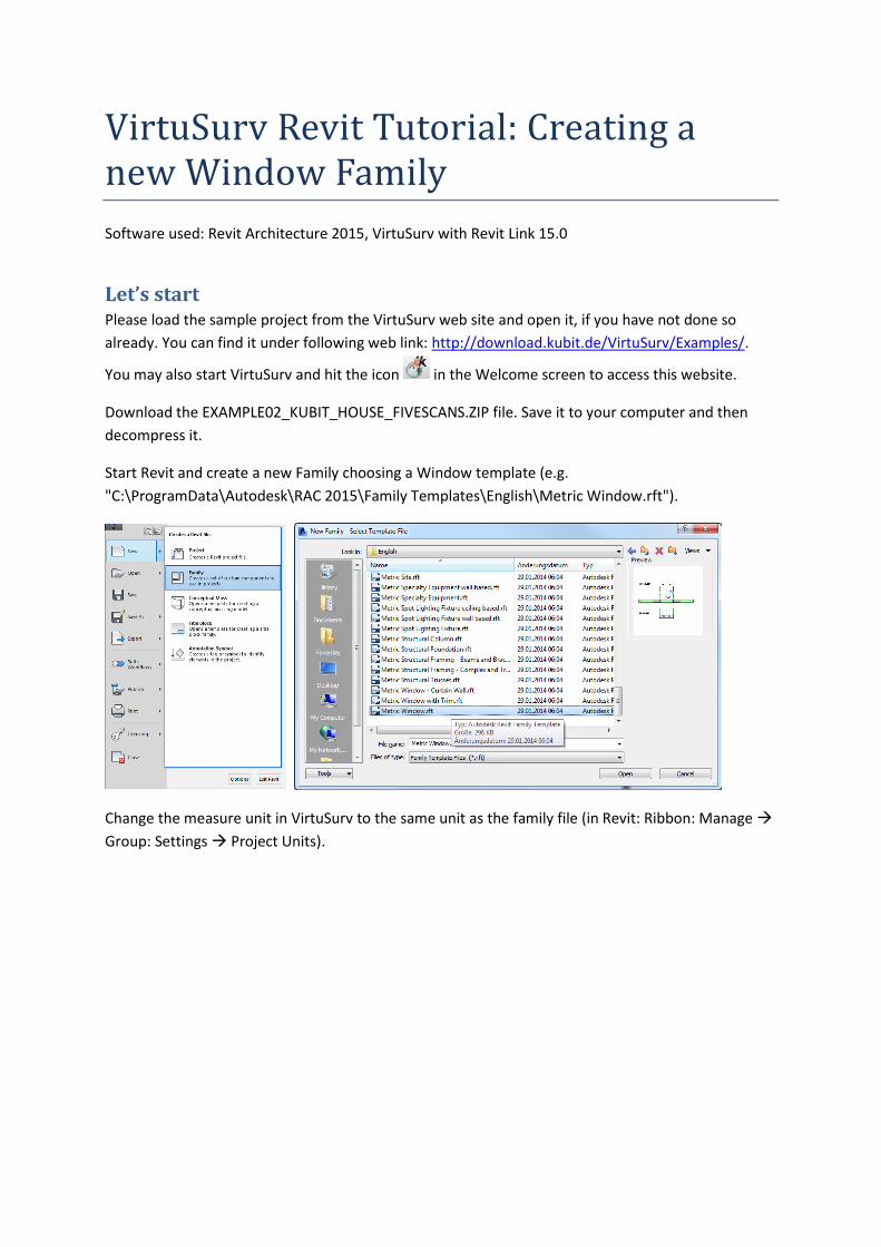
Start Revit and create a new Family choosing a Window template (e.g.
"C:\ProgramData\Autodesk\RAC 2015\Family Templates\English\Metric Window.rft").
Change the measure unit in VirtuSurv to the same unit as the family file (in Revit: Ribbon: Manage
Group: Settings Project Units).
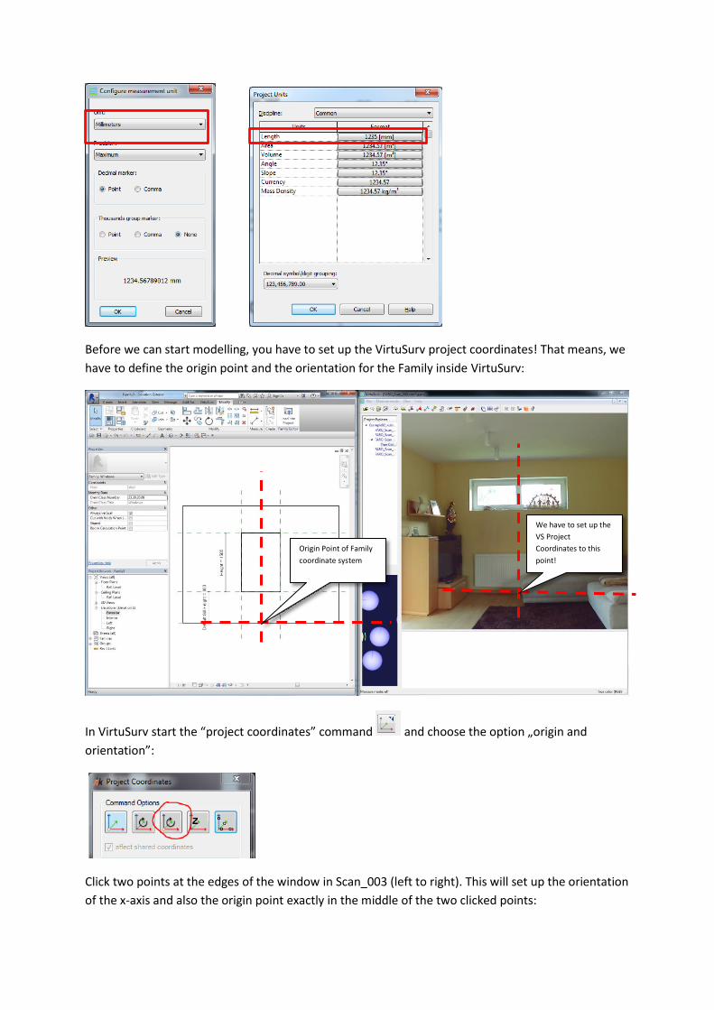
Before we can start modelling, you have to set up the VirtuSurv project coordinates! That means, we
have to define the origin point and the orientation for the Family inside VirtuSurv:
In VirtuSurv start the “project coordinates” command and choose the option „origin and
orientation”:
Click two points at the edges of the window in Scan_003 (left to right). This will set up the orientation
of the x-axis and also the origin point exactly in the middle of the two clicked points:
Origin Point of Family
coordinate system
We have to set up the
VS Project
Coordinates to this
point!
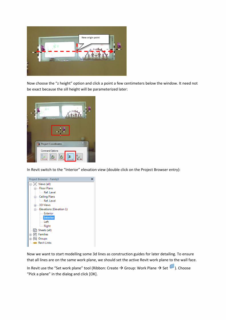
Now choose the “z height” option and click a point a few centimeters below the window. It need not
be exact because the sill height will be parameterized later:
In Revit switch to the “Interior” elevation view (double click on the Project Browser entry):
Now we want to start modelling some 3d lines as construction guides for later detailing. To ensure
that all lines are on the same work plane, we should set the active Revit work plane to the wall face.
In Revit use the “Set work plane” tool (Ribbon: Create Group: Work Plane Set ). Choose
“Pick a plane” in the dialog and click [OK].
New origin point
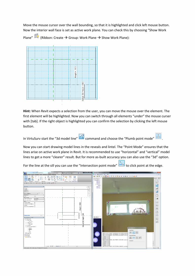
Move the mouse cursor over the wall bounding, so that it is highlighted and click left mouse button.
Now the interior wall face is set as active work plane. You can check this by choosing “Show Work
Plane” (Ribbon: Create Group: Work Plane Show Work Plane):
Hint: When Revit expects a selection from the user, you can move the mouse over the element. The
first element will be highlighted. Now you can switch through all elements “under” the mouse curser
with [tab]. If the right object is highlighted you can confirm the selection by clicking the left mouse
button.
In VirtuSurv start the “3d model line” command and choose the “Plumb point mode” .
Now you can start drawing model lines in the reveals and lintel. The “Point Mode” ensures that the
lines arise on active work plane in Revit. It is recommended to use “horizontal” and “vertical” model
lines to get a more “clearer” result. But for more as-built accuracy you can also use the “3d” option.
For the line at the sill you can use the “Intersection point mode” to click point at the edge.
Now we have the “skeleton” for the new window opening. Select the opening rectangle in Revit (use
the [tab] key to select the right object!). The green context Ribbon “Modify | Opening cut” appears.
Select “Edit Sketch” in the Group: Opening.
Revit turns over to the “Sketch editing mode”. That means now you can only edit the previously
selected element (the opening cut). Choose the “Pick Lines” tool (Ribbon: Modify|Opening
Edit Boundary Group: Draw) and click on all four model lines coming from VirtuSurv.
Choose the “Trim/Extend to Corner” tool (Ribbon: Modify|Opening > Edit Boundary Group:
Modify) and click the lines one after the other to trim. Cancel the current command with [Esc] (or
choose the selection arrow ) and select the “old” opening cut rectangle (if you press the [tab]
key while the cursor is over one line, you can select all connected lines at once) and press the [del]
key (or the “Delete” tool under Ribbon: Modify|Opening Edit Boundary Group: Modify).
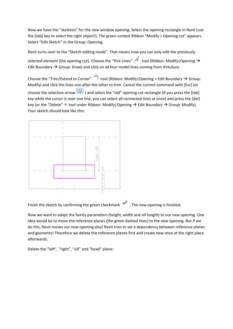
Your sketch should look like this:
Finish the sketch by confirming the green checkmark . The new opening is finished.
Now we want to adapt the family parameters (height, width and sill height) to our new opening. One
idea would be to move the reference planes (the green dashed lines) to the new opening. But if we
do this, Revit moves our new opening also! Revit tries to set a dependency between reference planes
and geometry! Therefore we delete the reference planes first and create new once at the right place
afterwards.
Delete the “left”, “right”, “sill” and “head” plane:
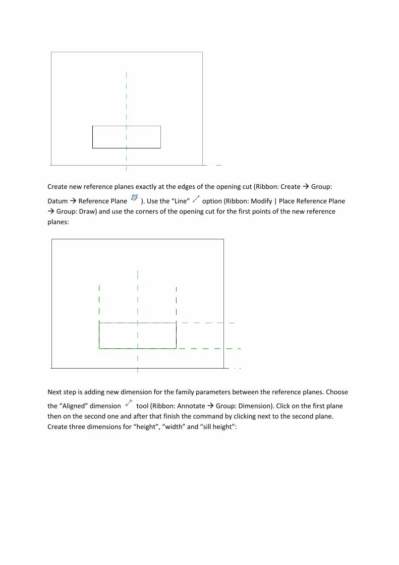
Create new reference planes exactly at the edges of the opening cut (Ribbon: Create Group:
Datum Reference Plane ). Use the “Line” option (Ribbon: Modify | Place Reference Plane
Group: Draw) and use the corners of the opening cut for the first points of the new reference
planes:
Next step is adding new dimension for the family parameters between the reference planes. Choose
the “Aligned” dimension tool (Ribbon: Annotate Group: Dimension). Click on the first plane
then on the second one and after that finish the command by clicking next to the second plane.
Create three dimensions for “height”, “width” and “sill height”:
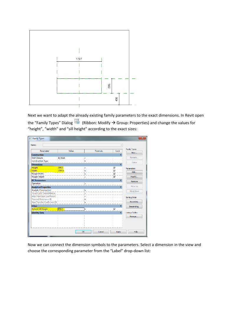
Next we want to adapt the already existing family parameters to the exact dimensions. In Revit open
the “Family Types” Dialog (Ribbon: Modify Group: Properties) and change the values for
“height”, “width” and “sill height” according to the exact sizes:
Now we can connect the dimension symbols to the parameters. Select a dimension in the view and
choose the corresponding parameter from the “Label” drop-down list:
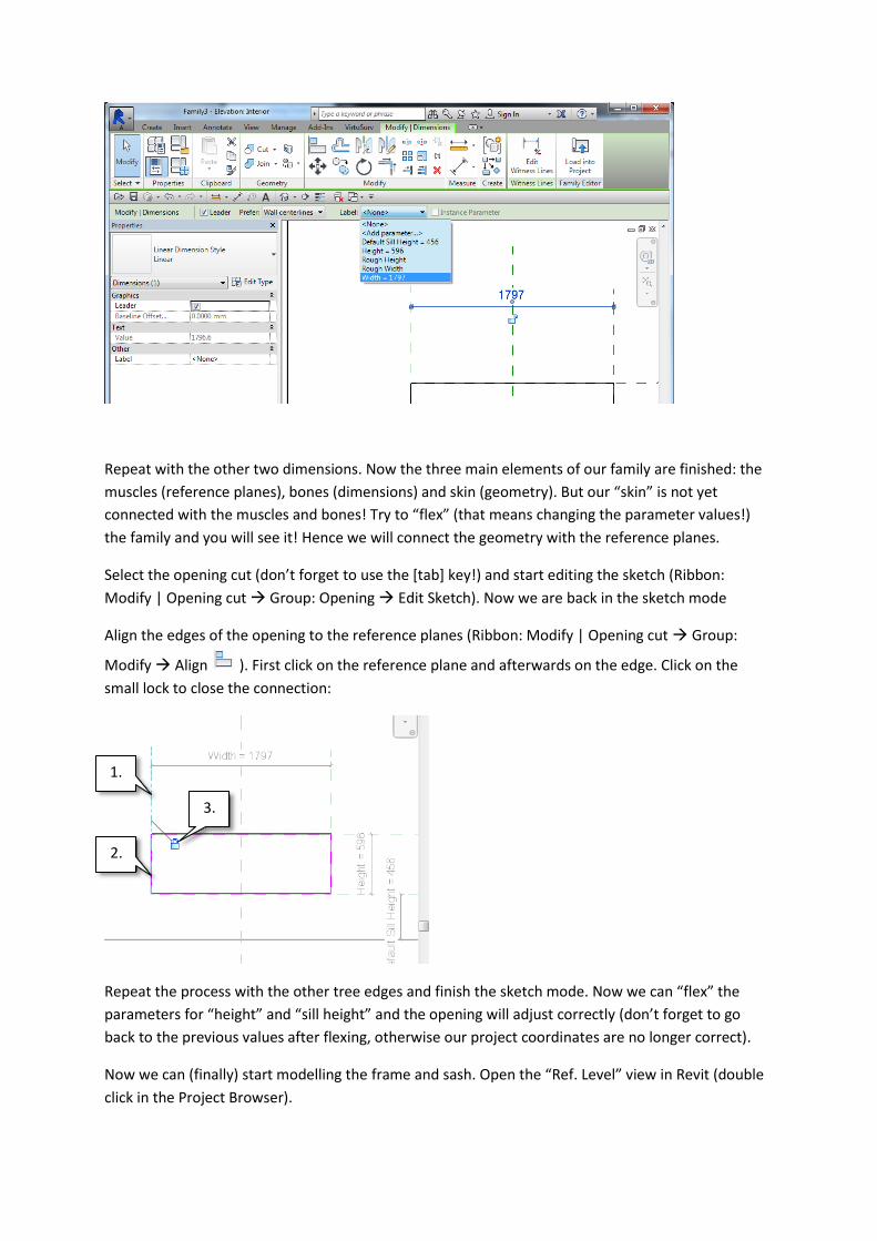
Repeat with the other two dimensions. Now the three main elements of our family are finished: the
muscles (reference planes), bones (dimensions) and skin (geometry). But our “skin” is not yet
connected with the muscles and bones! Try to “flex” (that means changing the parameter values!)
the family and you will see it! Hence we will connect the geometry with the reference planes.
Select the opening cut (don’t forget to use the [tab] key!) and start editing the sketch (Ribbon:
Modify | Opening cut Group: Opening Edit Sketch). Now we are back in the sketch mode
Align the edges of the opening to the reference planes (Ribbon: Modify | Opening cut Group:
Modify Align ). First click on the reference plane and afterwards on the edge. Click on the
small lock to close the connection:
Repeat the process with the other tree edges and finish the sketch mode. Now we can “flex” the
parameters for “height” and “sill height” and the opening will adjust correctly (don’t forget to go
back to the previous values after flexing, otherwise our project coordinates are no longer correct).
Now we can (finally) start modelling the frame and sash. Open the “Ref. Level” view in Revit (double
click in the Project Browser).
1.
2.
3.
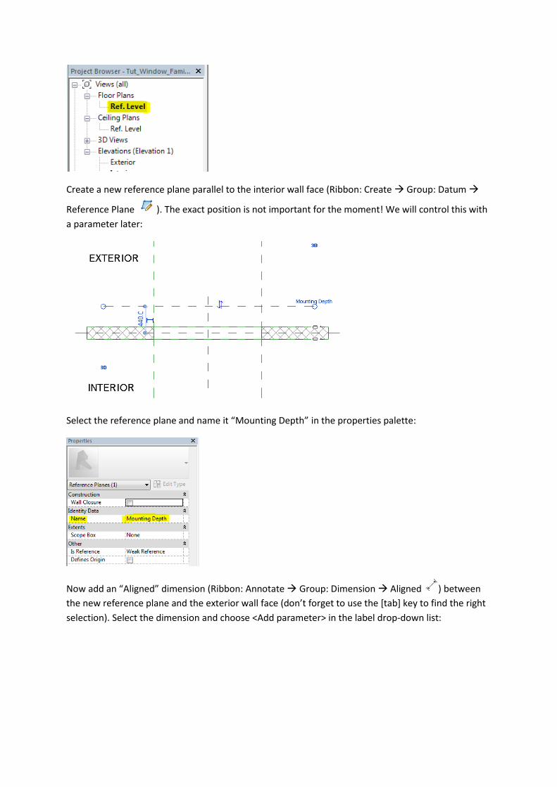
Create a new reference plane parallel to the interior wall face (Ribbon: Create Group: Datum
Reference Plane ). The exact position is not important for the moment! We will control this with
a parameter later:
Select the reference plane and name it “Mounting Depth” in the properties palette:
Now add an “Aligned” dimension (Ribbon: Annotate Group: Dimension Aligned ) between
the new reference plane and the exterior wall face (don’t forget to use the [tab] key to find the right
selection). Select the dimension and choose <Add parameter> in the label drop-down list:
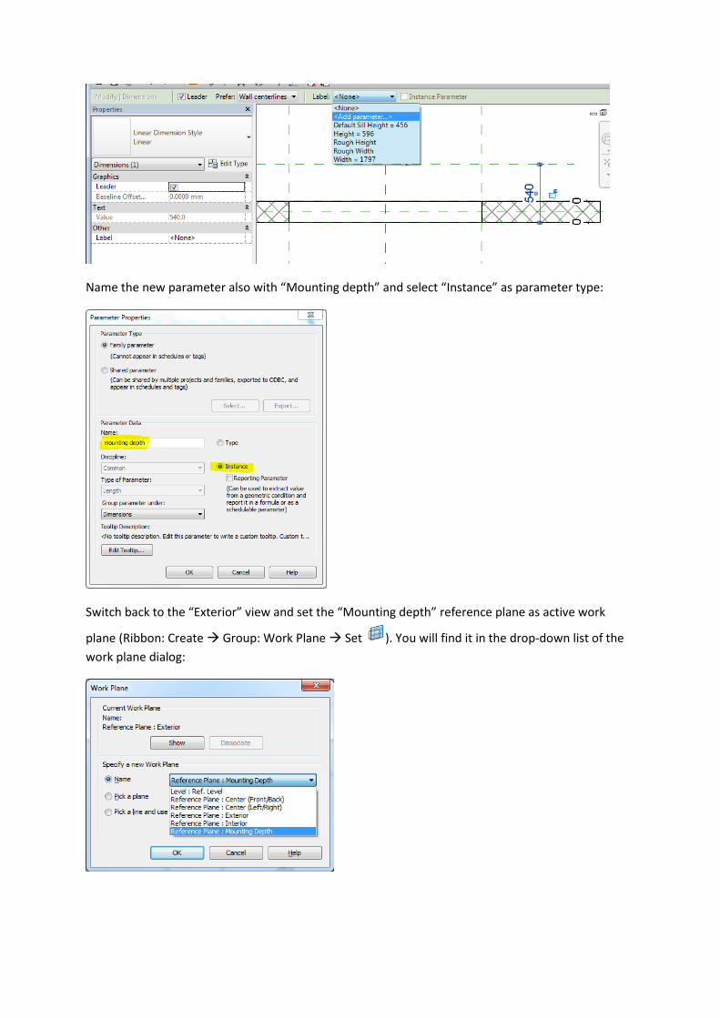
Name the new parameter also with “Mounting depth” and select “Instance” as parameter type:
Switch back to the “Exterior” view and set the “Mounting depth” reference plane as active work
plane (Ribbon: Create Group: Work Plane Set ). You will find it in the drop-down list of the
work plane dialog:
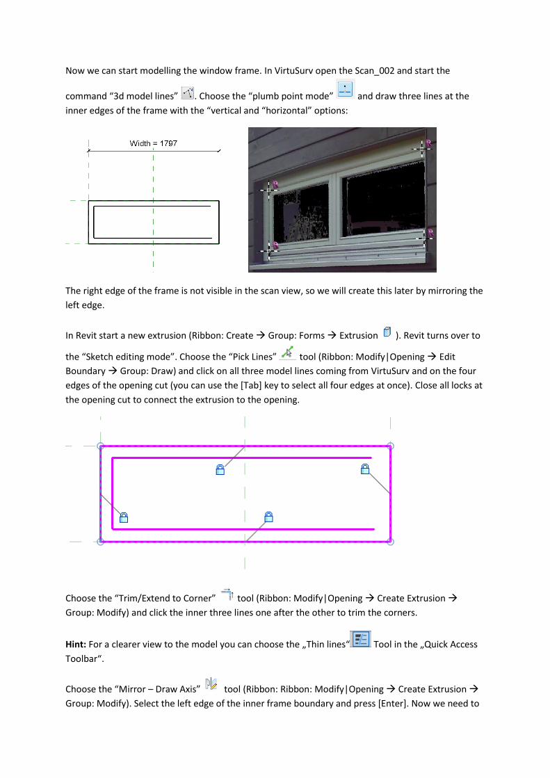
Now we can start modelling the window frame. In VirtuSurv open the Scan_002 and start the
command “3d model lines” . Choose the “plumb point mode” and draw three lines at the
inner edges of the frame with the “vertical and “horizontal” options:
The right edge of the frame is not visible in the scan view, so we will create this later by mirroring the
left edge.
In Revit start a new extrusion (Ribbon: Create Group: Forms Extrusion ). Revit turns over to
the “Sketch editing mode”. Choose the “Pick Lines” tool (Ribbon: Modify|Opening Edit
Boundary Group: Draw) and click on all three model lines coming from VirtuSurv and on the four
edges of the opening cut (you can use the [Tab] key to select all four edges at once). Close all locks at
the opening cut to connect the extrusion to the opening.
Choose the “Trim/Extend to Corner” tool (Ribbon: Modify|Opening Create Extrusion
Group: Modify) and click the inner three lines one after the other to trim the corners.
Hint: For a clearer view to the model you can choose the „Thin lines“ Tool in the „Quick Access
Toolbar“.
Choose the “Mirror – Draw Axis” tool (Ribbon: Ribbon: Modify|Opening Create Extrusion
Group: Modify). Select the left edge of the inner frame boundary and press [Enter]. Now we need to
draw the mirror axis. Move your mouse to the midpoint of the upper line at the opening cut. If the
midpoint snap symbol appears press left mouse button.
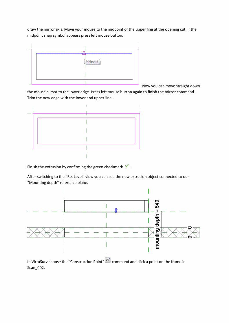
Now you can move straight down
the mouse cursor to the lower edge. Press left mouse button again to finish the mirror command.
Trim the new edge with the lower and upper line.
Finish the extrusion by confirming the green checkmark .
After switching to the “Re. Level” view you can see the new extrusion object connected to our
“Mounting depth” reference plane.
In VirtuSurv choose the “Construction Point” command and click a point on the frame in
Scan_002.
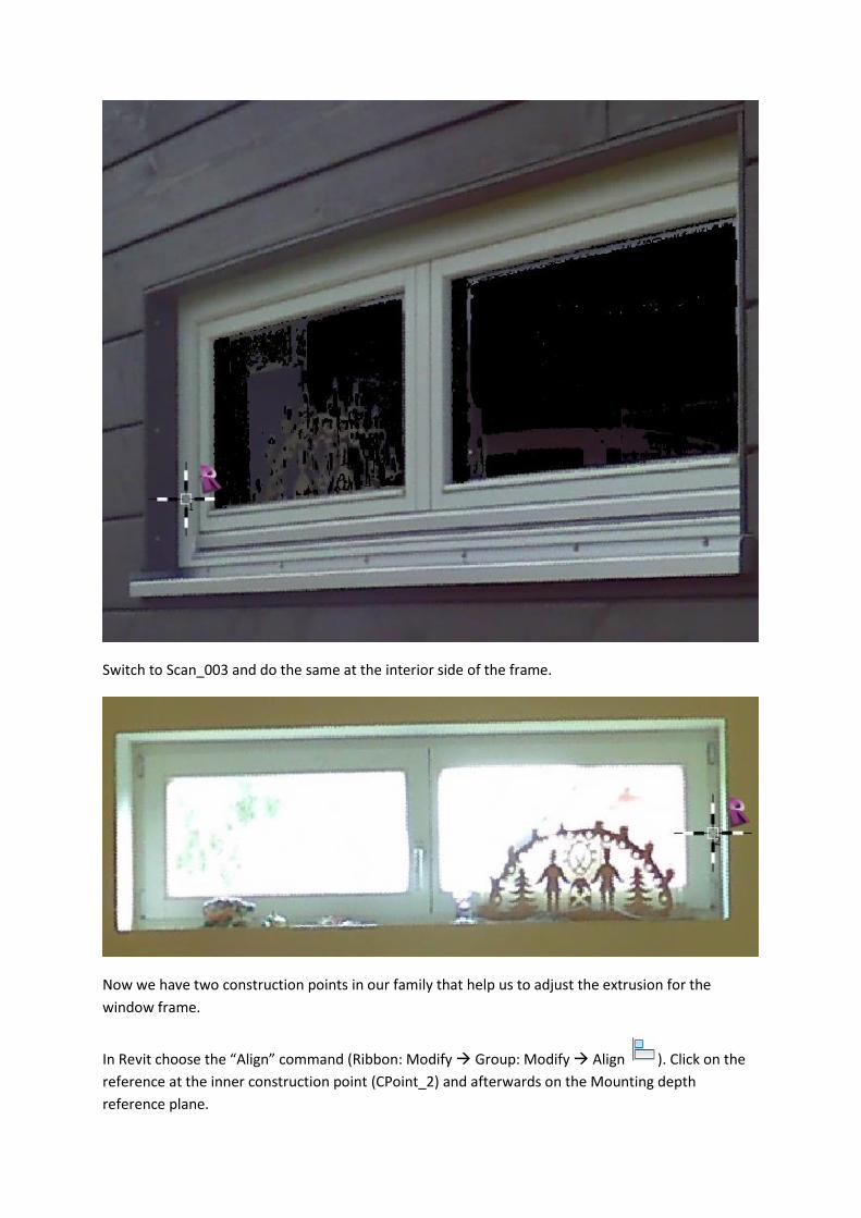
Switch to Scan_003 and do the same at the interior side of the frame.
Now we have two construction points in our family that help us to adjust the extrusion for the
window frame.
In Revit choose the “Align” command (Ribbon: Modify Group: Modify Align ). Click on the
reference at the inner construction point (CPoint_2) and afterwards on the Mounting depth
reference plane.
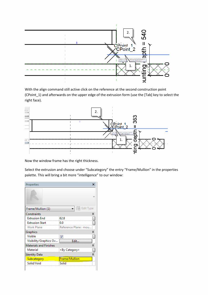
With the align command still active click on the reference at the second construction point
(CPoint_1) and afterwards on the upper edge of the extrusion form (use the [Tab] key to select the
right face).
Now the window frame has the right thickness.
Select the extrusion and choose under “Subcategory” the entry “Frame/Mullion” in the properties
palette. This will bring a bit more “intelligence” to our window:
1.
2.
1.
2.
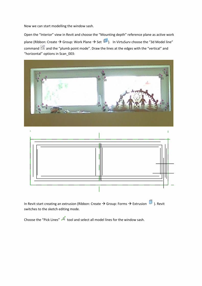
Now we can start modelling the window sash.
Open the “Interior” view in Revit and choose the “Mounting depth” reference plane as active work
plane (Ribbon: Create Group: Work Plane Set ). In VirtuSurv choose the “3d Model line”
command and the “plumb point mode”. Draw the lines at the edges with the “vertical” and
“horizontal” options in Scan_003:
In Revit start creating an extrusion (Ribbon: Create Group: Forms Extrusion ). Revit
switches to the sketch editing mode.
Choose the “Pick Lines” tool and select all model lines for the window sash.
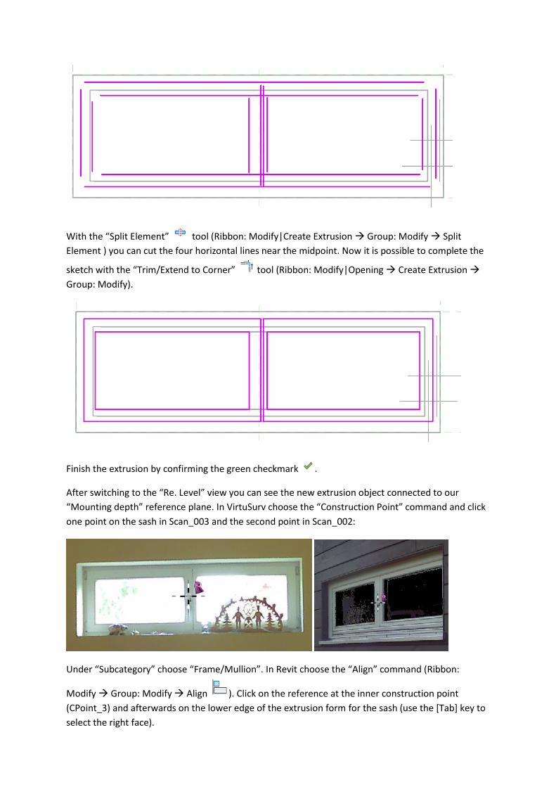
With the “Split Element” tool (Ribbon: Modify|Create Extrusion Group: Modify Split
Element ) you can cut the four horizontal lines near the midpoint. Now it is possible to complete the
sketch with the “Trim/Extend to Corner” tool (Ribbon: Modify|Opening Create Extrusion
Group: Modify).
Finish the extrusion by confirming the green checkmark .
After switching to the “Re. Level” view you can see the new extrusion object connected to our
“Mounting depth” reference plane. In VirtuSurv choose the “Construction Point” command and click
one point on the sash in Scan_003 and the second point in Scan_002:
Under “Subcategory” choose “Frame/Mullion”. In Revit choose the “Align” command (Ribbon:
Modify Group: Modify Align ). Click on the reference at the inner construction point
(CPoint_3) and afterwards on the lower edge of the extrusion form for the sash (use the [Tab] key to
select the right face).
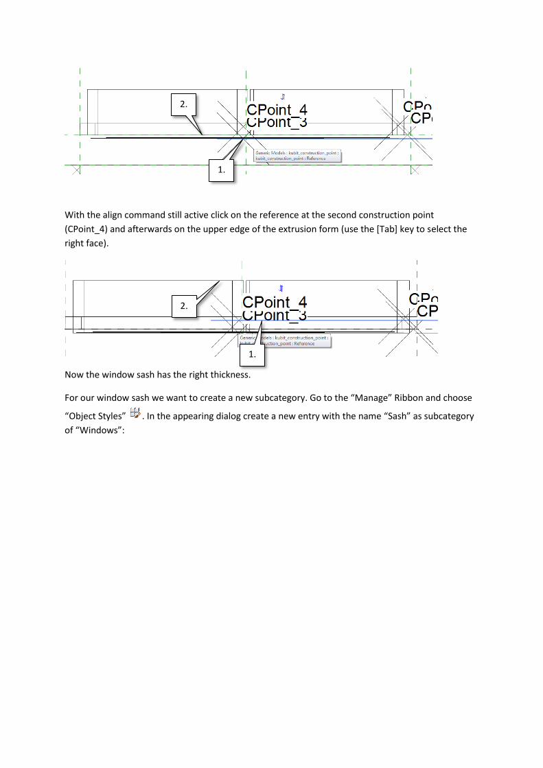
With the align command still active click on the reference at the second construction point
(CPoint_4) and afterwards on the upper edge of the extrusion form (use the [Tab] key to select the
right face).
Now the window sash has the right thickness.
For our window sash we want to create a new subcategory. Go to the “Manage” Ribbon and choose
“Object Styles” . In the appearing dialog create a new entry with the name “Sash” as subcategory
of “Windows”:
1.
2.
1.
2.
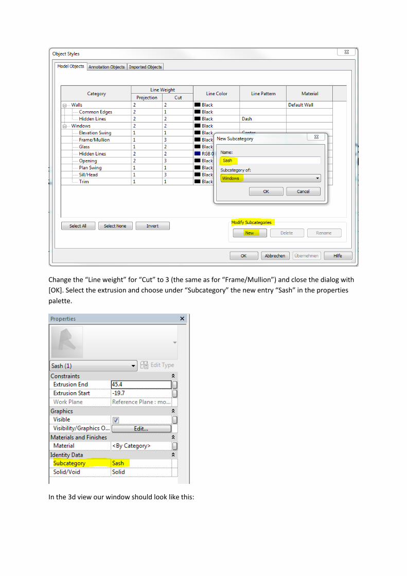
Change the “Line weight” for “Cut” to 3 (the same as for “Frame/Mullion”) and close the dialog with
[OK]. Select the extrusion and choose under “Subcategory” the new entry “Sash” in the properties
palette.
In the 3d view our window should look like this:
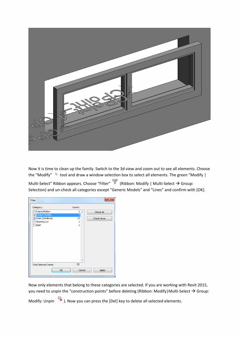
Now it is time to clean up the family. Switch to the 3d view and zoom out to see all elements. Choose
the “Modify” tool and draw a window selection box to select all elements. The green “Modify |
Multi-Select” Ribbon appears. Choose “Filter” (Ribbon: Modify | Multi-Select Group:
Selection) and un-check all categories except “Generic Models” and “Lines” and confirm with [OK].
Now only elements that belong to these categories are selected. If you are working with Revit 2015,
you need to unpin the “construction points” before deleting (Ribbon: Modify|Multi-Select Group:
Modify: Unpin ). Now you can press the [Del] key to delete all selected elements.
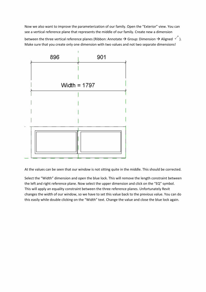
Now we also want to improve the parameterization of our family. Open the “Exterior” view. You can
see a vertical reference plane that represents the middle of our family. Create new a dimension
between the three vertical reference planes (Ribbon: Annotate Group: Dimension Aligned ).
Make sure that you create only one dimension with two values and not two separate dimensions!
At the values can be seen that our window is not sitting quite in the middle. This should be corrected.
Select the “Width” dimension and open the blue lock. This will remove the length constraint between
the left and right reference plane. Now select the upper dimension and click on the “EQ” symbol.
This will apply an equality constraint between the three reference planes. Unfortunately Revit
changes the width of our window, so we have to set this value back to the previous value. You can do
this easily while double clicking on the “Width” text. Change the value and close the blue lock again.
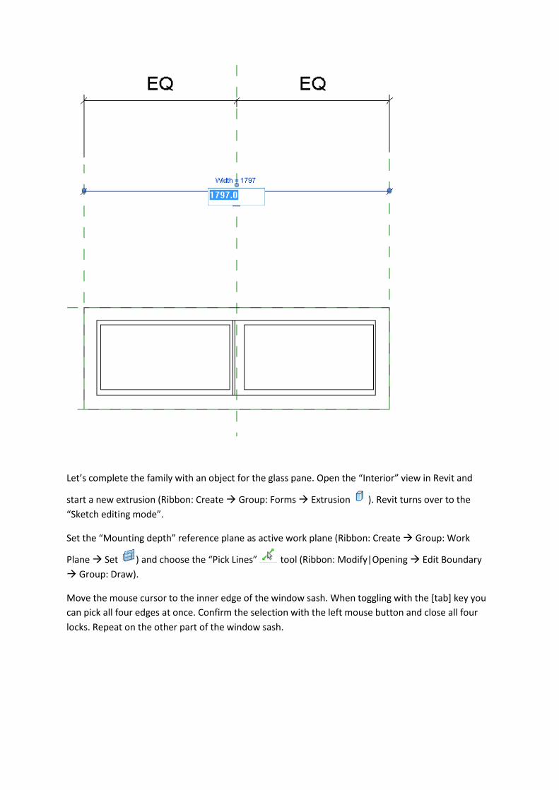
Let’s complete the family with an object for the glass pane. Open the “Interior” view in Revit and
start a new extrusion (Ribbon: Create Group: Forms Extrusion ). Revit turns over to the
“Sketch editing mode”.
Set the “Mounting depth” reference plane as active work plane (Ribbon: Create Group: Work
Plane Set ) and choose the “Pick Lines” tool (Ribbon: Modify|Opening Edit Boundary
Group: Draw).
Move the mouse cursor to the inner edge of the window sash. When toggling with the [tab] key you
can pick all four edges at once. Confirm the selection with the left mouse button and close all four
locks. Repeat on the other part of the window sash.
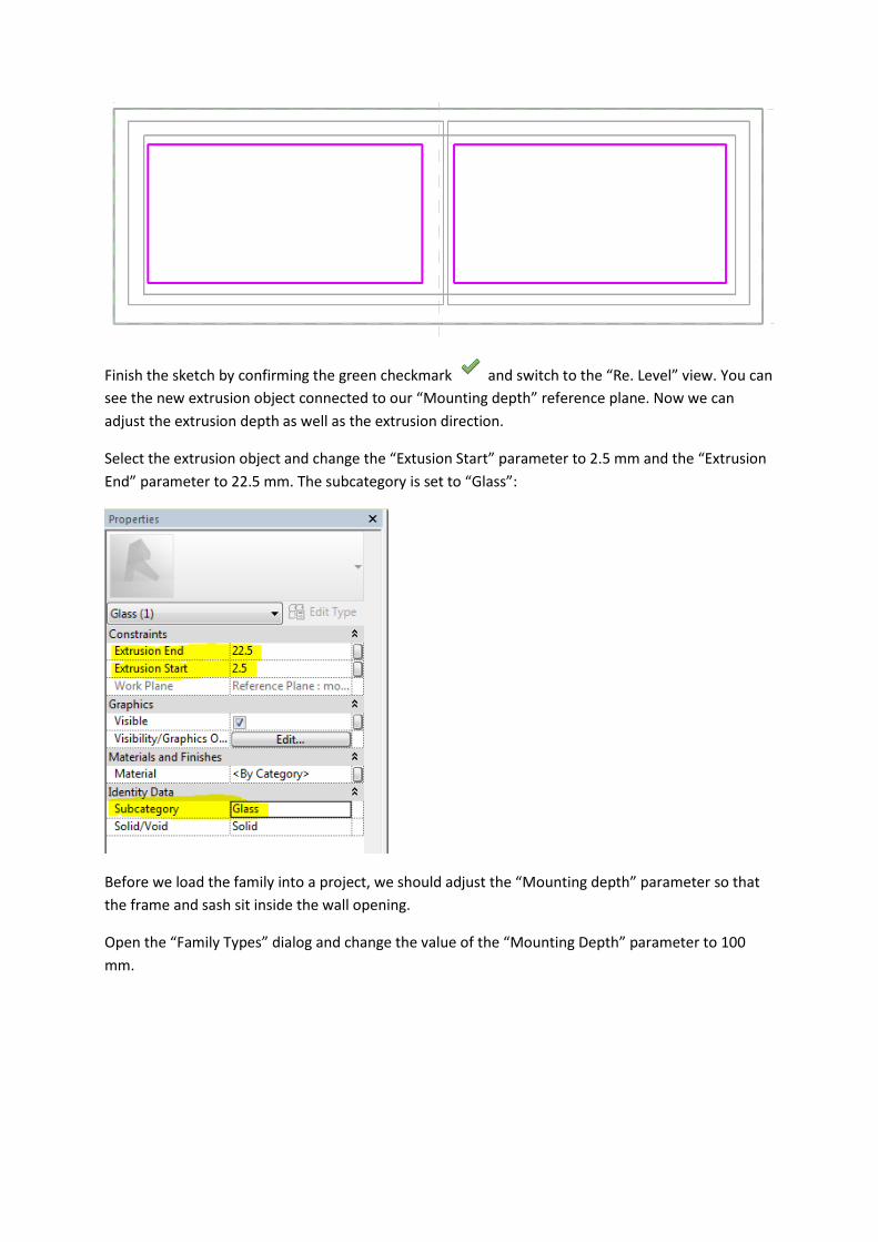
Finish the sketch by confirming the green checkmark and switch to the “Re. Level” view. You can
see the new extrusion object connected to our “Mounting depth” reference plane. Now we can
adjust the extrusion depth as well as the extrusion direction.
Select the extrusion object and change the “Extusion Start” parameter to 2.5 mm and the “Extrusion
End” parameter to 22.5 mm. The subcategory is set to “Glass”:
Before we load the family into a project, we should adjust the “Mounting depth” parameter so that
the frame and sash sit inside the wall opening.
Open the “Family Types” dialog and change the value of the “Mounting Depth” parameter to 100
mm.
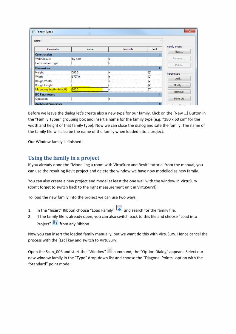
Before we leave the dialog let’s create also a new type for our family. Click on the [New …] Button in
the “Family Types” grouping box and insert a name for the family type (e.g. “180 x 60 cm” for the
width and height of that family type). Now we can close the dialog and safe the family. The name of
the family file will also be the name of the family when loaded into a project.
Our Window family is finished!
Using the family in a project If you already done the “Modelling a room with VirtuSurv and Revit” tutorial from the manual, you
can use the resulting Revit project and delete the window we have now modelled as new family.
You can also create a new project and model at least the one wall with the window in VirtuSurv
(don’t forget to switch back to the right measurement unit in VirtuSurv!).
To load the new family into the project we can use two ways:
1. In the “Insert” Ribbon choose “Load Family” and search for the family file.
2. If the family file is already open, you can also switch back to this file and choose “Load into
Project” from any Ribbon.
Now you can insert the loaded family manually, but we want do this with VirtuSurv. Hence cancel the
process with the [Esc] key and switch to VirtuSurv.
Open the Scan_003 and start the “Window” command, the “Option Dialog” appears. Select our
new window family in the “Type” drop-down list and choose the “Diagonal Points” option with the
“Standard” point mode:
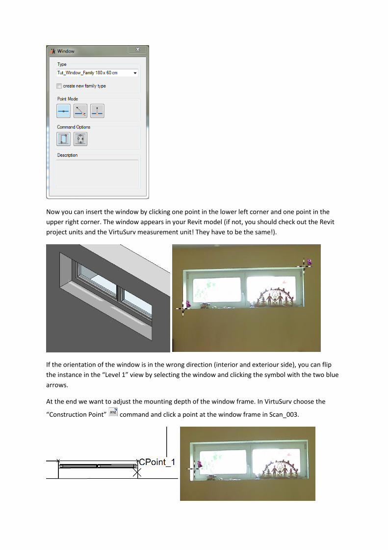
Now you can insert the window by clicking one point in the lower left corner and one point in the
upper right corner. The window appears in your Revit model (if not, you should check out the Revit
project units and the VirtuSurv measurement unit! They have to be the same!).
If the orientation of the window is in the wrong direction (interior and exteriour side), you can flip
the instance in the “Level 1” view by selecting the window and clicking the symbol with the two blue
arrows.
At the end we want to adjust the mounting depth of the window frame. In VirtuSurv choose the
“Construction Point” command and click a point at the window frame in Scan_003.
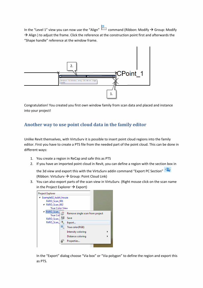
In the “Level 1” view you can now use the “Align” command (Ribbon: Modify Group: Modify
Align ) to adjust the frame. Click the reference at the construction point first and afterwards the
“Shape handle” reference at the window frame.
Congratulation! You created you first own window family from scan data and placed and instance
into your project!
Another way to use point cloud data in the family editor
Unlike Revit themselves, with VirtuSurv it is possible to insert point cloud regions into the family
editor. First you have to create a PTS file from the needed part of the point cloud. This can be done in
different ways:
1. You create a region in ReCap and safe this as PTS
2. If you have an imported point cloud in Revit, you can define a region with the section box in
the 3d view and export this with the VirtuSurv addin command “Export PC Section”
(Ribbon: VirtuSurv Group: Point Cloud Link)
3. You can also export parts of the scan view in VirtuSurv. (Right mouse click on the scan name
in the Project Explorer Export)
In the “Export” dialog choose “Via box” or “Via polygon” to define the region and export this
as PTS.
1.
2.
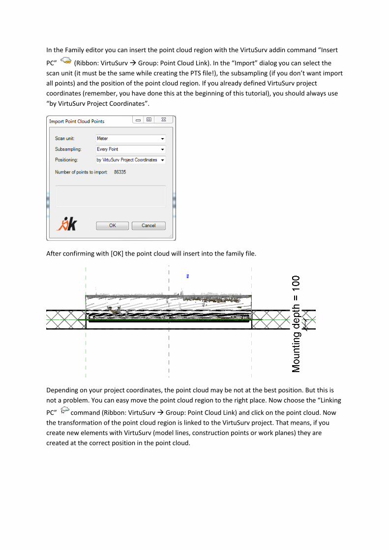
In the Family editor you can insert the point cloud region with the VirtuSurv addin command “Insert
PC” (Ribbon: VirtuSurv Group: Point Cloud Link). In the “Import” dialog you can select the
scan unit (it must be the same while creating the PTS file!), the subsampling (if you don’t want import
all points) and the position of the point cloud region. If you already defined VirtuSurv project
coordinates (remember, you have done this at the beginning of this tutorial), you should always use
“by VirtuSurv Project Coordinates”.
After confirming with [OK] the point cloud will insert into the family file.
Depending on your project coordinates, the point cloud may be not at the best position. But this is
not a problem. You can easy move the point cloud region to the right place. Now choose the “Linking
PC” command (Ribbon: VirtuSurv Group: Point Cloud Link) and click on the point cloud. Now
the transformation of the point cloud region is linked to the VirtuSurv project. That means, if you
create new elements with VirtuSurv (model lines, construction points or work planes) they are
created at the correct position in the point cloud.