viscoelastic characteristics of mechanically assembled...
TRANSCRIPT
Haibo LiState Key Laboratory of Ocean Engineering,
School of Naval Architecture, Ocean and Civil Engineering,
Shanghai Jiao Tong University,
Shanghai 200240, China;
Department of Civil and Environmental Engineering;
Department of Mechanical Engineering;
Department of Materials Science and Engineering,
Northwestern University,
Evanston, IL 60208
Xi WangState Key Laboratory of Ocean Engineering,
School of Naval Architecture, Ocean and Civil Engineering,
Shanghai Jiao Tong University,
Shanghai 200240, China
Feng ZhuDepartment of Civil and Environmental Engineering;
Department of Mechanical Engineering;
Department of Materials Science and Engineering,
Northwestern University,
Evanston, IL 60208;
School of Logistics Engineering,
Wuhan University of Technology,
Wuhan 430063, China
Xin Ning1
Department of Materials Science and Engineering,
Frederick Seitz Materials Research Laboratory,
University of Illinois at Urbana-Champaign,
Urbana, IL 61801
Heling Wang2
Department of Civil and Environmental Engineering;
Department of Mechanical Engineering;
Department of Materials Science and Engineering,
Northwestern University,
Evanston, IL 60208
e-mail: [email protected]
John A. RogersDepartment of Materials Science and Engineering;
Department of Biomedical Engineering;
Department of Chemistry;
Department of Mechanical Engineering;
Department of Electrical Engineering and Computer Science;
Department of Neurological Surgery,
Center for Bio-Integrated Electronics,
Simpson Querrey Institute for BioNanotechnology,
McCormick School of Engineering and
Feinberg School of Medicine,
Northwestern University,
Evanston, IL 60208
Yihui ZhangCenter for Flexible Electronics Technology and
Center for Mechanics and Materials,
Beijing 100084, China;
AML, Department of Engineering Mechanics,
Tsinghua University,
Beijing 100084, China
Yonggang HuangDepartment of Civil and Environmental Engineering;
Department of Mechanical Engineering;
Department of Materials Science and Engineering;
Center for Bio-Integrated Electronics,
Northwestern University,
Evanston, IL 60208
Viscoelastic Characteristics ofMechanically Assembled Three-Dimensional Structures Formedby Compressive BucklingVibrational microplatforms that exploit complex three-dimensional (3D) architecturesassembled via the controlled compressive buckling technique represent promising candi-dates in 3D micro-electromechanical systems (MEMS), with a wide range of applicationssuch as oscillators, actuators, energy harvesters, etc. However, the accuracy and effi-ciency of such 3D MEMS might be significantly reduced by the viscoelastic dampingeffect that arises from material viscosity. Therefore, a clear understanding and charac-terization of such effects are essential to progress in this area. Here, we present a studyon the viscoelastic damping effect in complex 3D structures via an analytical model andfinite element analysis (FEA). By adopting the Kelvin–Voigt model to characterize thematerial viscoelasticity, an analytical solution is derived for the vibration of a buckledribbon. This solution then yields a scaling law for the half-band width or the quality fac-tor of vibration that can be extended to other classes of complex 3D structures, as vali-dated by FEA. The scaling law reveals the dependence of the half-band width on thegeometries of 3D structures and the compressive strain. The results could serve as guide-lines to design novel 3D vibrational microplatforms for applications in MEMS and otherareas of technology. [DOI: 10.1115/1.4041163]
Keywords: viscoelasticity, half-band width, controlled compressive buckling, complexthree-dimensional structure
1Present address: Department of Aerospace Engineering, The Pennsylvania StateUniversity, University Park, PA 16802
2Corresponding author.Contributed by the Applied Mechanics Division of ASME for publication in the
JOURNAL OF APPLIED MECHANICS. Manuscript received July 9, 2018; final manuscriptreceived August 5, 2018; published online August 31, 2018. Assoc. Editor: PradeepSharma.
Journal of Applied Mechanics DECEMBER 2018, Vol. 85 / 121002-1Copyright VC 2018 by ASME
Downloaded From: https://appliedmechanics.asmedigitalcollection.asme.org on 12/18/2018 Terms of Use: http://www.asme.org/about-asme/terms-of-use

1 Introduction
Micro- and nanostructures in micro-electromechanical systems(MEMS) are of significant current research interest, due partly totheir relevance to wide ranging classes of applications in biomedi-cine [1–3], sensors [4–6], electronics and optoelectronics [7–9],batteries and supercapacitors [10–12], robotics [13–15], andothers [16,17]. In MEMS, structural vibration plays a key role inthe transformation from mechanical signals to electrical signals[18,19]. The utilization of three-dimensional (3D) micro- andnanostructures provide significant advantages and design flexibil-ity compared to those based on two-dimensional (2D) structures[20–23], especially in areas of energy harvesting, sensing of ani-sotropic mechanical properties, and simultaneous evaluation ofmultiple mechanical properties (density, modulus, etc.), due totheir ability to support multidirectional vibrations and controlledvibration modes [24].
Diverse manufacturing techniques based on phenomena such asmechanical buckling [25–28], self-folding induced by residualstress [29–32], surface instabilities [33–35], capillary forces[36–38], and temperature changes [39,40] can provide access to3D micro- and nanostructures. Among these methods, the com-pressive buckling approach is notable for its ability to constructcomplex 3D structures with vibration behaviors (e.g., natural fre-quency) that can be tuned by applying tensile strain to the soft,elastomeric assembly platform. In addition, this technique is com-patible with a variety of active materials, such as poly (vinylidenefluoride), Pb(Zr,Ti)O3 (PZT), and conductive metals, allowingactuation by external stimuli based on electric and/or magneticfields. Such options provide great potential in the applications ofresonators, energy harvesters, and other systems based on continu-ous adaption of the resonant frequency or vibration modes [24].
One major challenge in the design of 3D MEMS arises fromthe effects of viscoelasticity in the constituent materials. Sucheffects lead to dissipation of energy, changes in stress distribu-tions, displacements, and frequencies during vibration [41–45].For example, increases in the ambient temperature and/or humid-ity can increase the viscosity [46–48], which, in turn, can reducethe efficiency of 3D MEMS devices. The viscoelastic propertiescan be characterized by dynamic mechanical analysis [49] andcreep and stress relaxation methods [50] for a wide range of mate-rials, such as poly(methyl methacrylate), SU8 epoxy resin, poly-propylene, polydimethylsiloxane, etc. [51–55]. The viscoelasticdamping effect due to viscosity of materials in a vibration systemcan be characterized by the half bandwidth n or the quality factorQ (Q ¼ 1= 2nð Þ) [56–58].
Several viscoelastic models have been proposed to characterizethe viscoelastic material properties including Maxwell model,Kelvin–Voigt model, and standard linear solid model [59–61].Among them, the Kelvin–Voigt model is a classical and widelyused viscoelastic model. For example, Ghayesh [62] investigatedthe nonlinear dynamic response of a simply supported beam sup-ported by a nonlinear spring. Mahmoodi et al. [63] reported theexperimental study of nonlinear vibration and frequencyresponses of viscoelastic beams, with good agreement betweenexperimental results and numerical simulations. Kolahchi [64]studied the nonlinear vibrations of viscoelastic rectangular plates.These investigations focus on the viscoelastic damping effect of2D plates or beams. Though Tseng and Dugundji [65] investigatedthe vibration of a buckled beam, they only provided an exact solu-tion for the case without viscoelastic damping. Similarly, Cottoneet al. [66] studied piezoelectric buckled beams as a vibrationenergy harvester. The aforementioned theoretical models arerestricted to a few simple geometries and cannot be directlyextended to complex 3D structures. Therefore, it is important todevelop a theoretical model to predict the viscoelastic dampingeffect of vibrations in complex 3D structures.
This paper presents a study on the viscoelastic characteristics of3D mechanically assembled structures formed by compressivebuckling techniques via an analytical model and finite element
analysis (FEA). The Kelvin–Voigt model is used to capture theviscoelastic effects of conventional materials (SU8, PVDF, etc.) inthese structures. An analytical model explicitly relates the half-band width of a buckled ribbon to the geometry/material parametersand the compressive strain. Then, a more general model describesthe half-band width of complex structures, with two fitting parame-ters to account for the complexity of the vibration mode and struc-ture. The models are validated by FEA with good agreement. Theyprovide insights into the effect of design parameters (material, com-pressive strain, structure shape, etc.) on the vibration behavior andmay serve as useful references in the design of 3D vibrational plat-forms and the potential applications of 3D MEMS.
2 The Viscoelastic Characteristics of Three-
Dimensional Buckled Ribbon and Three-Dimensional
Structures
A schematic illustration of a buckled ribbon excited by anexternal harmonic load is shown in Fig. 1. A straight 2D slenderribbon (length L, width b, and thickness h) is selectively bondedto a highly prestrained elastomer at two ends as shown in Fig.1(a). Release of the prestrain induces compression and triggersbuckling of the ribbon into the arch shape, as shown in Fig. 1(b),where l represents the distance between two bonding sites aftercompression. Considering that the viscosity of the soft elastomermay increase the half-band width of vibration, the buckled ribbonis transferred on to a rigid base using the technique reported byYan et al. [67]. An external harmonic load (see Fig. 1(c)) thenactuates the first-order vibration mode shown in Fig. 1(d).Because of the base has larger modulus than the buckled ribbon,its deformation can be neglected during the vibration analysis.Due to the ribbon thickness (h) is much smaller than its width (b)and length (L), finite-deformation beam theory with no sheardeformation [68–70] is adopted to establish an analytical model.In general, the deformations of a planar ribbon can be describedby the displacement of the central axis u¼ uiEi [71] and the twistangle w [68], where Ei is the unit vector before deformation in theCartesian coordinates (X, Y, Z), which all calculations are basedon. For the post-buckling and vibration shown in Fig. 1, only thedisplacement components in the X–Z plane are involved.
2.1 The Construction of Governing Equations. For a mod-erate level of compressive strain (e.g.,< 30%), the displacementsof the ribbon after the post-buckling could be expressed as[24,72,73]
u1 0ð Þ ¼ A 0ð Þ cos2pL
Z
� �þ 1
� �; u3 0ð Þ ¼
pA20ð Þ
4Lsin
4pL
Z
� �� ecompreZ
(1)
where ecompre ¼ L� l=L is the relative dimensional changebetween the two bonding sites, or called the compressive strain;ecompre is related to the elastomer prestrain eprestrain via
ecompre ¼ eprestrain= 1þ eprestrainð Þ; ec ¼ p2h2= 3L2ð Þ is the critical
strain; and A 0ð Þ ¼ffiffiffiffiffiffiffiffiffiffiffiffiffiffiffiffiffiffiffiffiffiffiffiffiffiffiffiffiffiffiffiffiffiffiffiffiffiffiffiffiffiffiffiffiffiffiffiffi3L2ecompre � p2h2� �
=3p2
q¼ L=p
ffiffiffiffiffiffiffiffiffiffiffiffiffiffiffiffiffiffiffiffiffiffiecompre � ecp
is the static deflection amplitude of the buckled ribbon. Due to therigidity of the fix stage, the boundary conditions are
u1 6L=2ð Þ ¼ 0; u3 6L=2ð Þ ¼ 0;du1
dZ6L=2ð Þ ¼ 0 (2)
Then a vibration displacement function Dui Z; tð Þ is superimposedon ui 0ð Þ Zð Þ to give the total displacement of the buckled ribbon as
u1 Z; tð Þ ¼ u1 0ð Þ þ Du1 Z; tð Þ; u3 Z; tð Þ ¼ u3 0ð Þ þ Du3 Z; tð Þ (3)
By introducing a set of series u kð Þ Zð Þ and / kð Þ Zð Þ into the vibra-tion displacements, the total displacements of the buckled ribboncan be further written as
121002-2 / Vol. 85, DECEMBER 2018 Transactions of the ASME
Downloaded From: https://appliedmechanics.asmedigitalcollection.asme.org on 12/18/2018 Terms of Use: http://www.asme.org/about-asme/terms-of-use

u1 Z; tð Þ ¼ u1 0ð Þ þ Du1 Z; tð Þ ¼ u1 0ð Þ þXn
k¼1
Da kð Þ tð Þu kð Þ Zð Þ (4)
u3 Z; tð Þ ¼ u3 0ð Þ þ Du3 Z; tð Þ ¼ u3 0ð Þ þXn
k¼1
Da kð Þ tð Þ/ kð Þ Zð Þ (5)
The total displacements should satisfy the boundary conditions inEq. (2), leading to
u kð Þ 6L=2ð Þ ¼ 0; / kð Þ 6L=2ð Þ ¼ 0 andduk
dZ6L=2ð Þ ¼ 0 (6)
To describe the viscoelastic characteristics of the buckled ribbon,the physical relationship for Kelvin–Voigt model is introduced as
r ¼ re þ rd ¼ Ee X;Z; tð Þ þ gE@e X;Z; tð Þ
@t(7)
where r is the stress, e is the strain, and E and g are the elasticmodulus and viscoelastic damping coefficient of the ribbon mate-rial, respectively. According to the beam theory
e ¼ k� 1ð Þ � Xj (8)
where k is the stretch ratio and j is the curvature. Noe that X rep-resents the distance from a point on the cross section to the centralaxis of the ribbon, where the origin of the coordinate systemlocates at.
To solve Da kð Þ tð Þ in Eqs. (4) and (5), the Lagrange’s equationof motion is introduced. Specifically, the strain energy Ws of thebuckled ribbon is given by [74]
Ws ¼1
2
ðL=2
�L=2
Ebh k� 1ð Þ2dZ þ 1
24
ðL=2
�L=2
Ebh3j2dZ (9)
By neglecting the terms of the third and higher order power of Dain Eq. (9), the potential energy can be also written as
Ws ¼ 1=2DaTKDa, in which Da is a n� 1 vector Da 1ð Þ;
Da 2ð Þ;…;Da nð ÞgT, and K is an n� n stiffness matrix. Similarly,
the kinetic energy can be given as
T D _að Þ ¼ 1
2
ðL=2
�L=2
qbh@u1 vð Þ@t
� �2
þ@u3 vð Þ@t
� �2" #
dZ ¼ 1
2D _aTMD _a
(10)
where D _a ¼ D _a 1ð Þ;D _a 2ð Þ;…;D _a nð Þ T
is the time derivative ofDa, i.e., D _a ¼ d Dað Þ=dt, q is the density of the ribbon material,and M is an n� n mass matrix.
Based on Eq. (7), the dissipation function of the buckled ribboncan be obtained as follows:
D ¼ 1
2
ðL=2
�L=2
gEbh@k@t
� �2
dZ þ 1
24
ðL=2
�L=2
gEbh3 @j@t
� �2
dZ (11)
The potential energy of the external harmonic load can be writtenas
Wext ¼ �ðL=2
�L=2
PðtÞDu1ðZ; tÞdZ (12)
where PðtÞ is the external force exerted on per unit length ofbucked ribbon and x is the frequency of the external harmonicload.
The Lagrange’s equation of motion requires that
@ T �Wsð Þ@Da
� d
dt
@ T �Wsð Þ@D _a
� @D
@D _a� @Wext
@Da¼ 0 (13)
By substituting Eqs. (7)–(12) into Eq. (13), the governing equationof the buckled ribbon under an external harmonic load is obtainedas
MD€a þ CD _a þ KDa ¼ F (14)
Fig. 1 Illustration of (a) a straight ribbon attached to a prestrained substrate at selected bond-ing sites, (b) the compressive post-buckling induced by the contraction of the elastomer, (c)the external load, and (d) the first-order vibration mode. Two phases corresponding to the larg-est vibration amplitudes are shown, i.e., up line: phase 0 deg, down line: phase 180 deg.
Journal of Applied Mechanics DECEMBER 2018, Vol. 85 / 121002-3
Downloaded From: https://appliedmechanics.asmedigitalcollection.asme.org on 12/18/2018 Terms of Use: http://www.asme.org/about-asme/terms-of-use
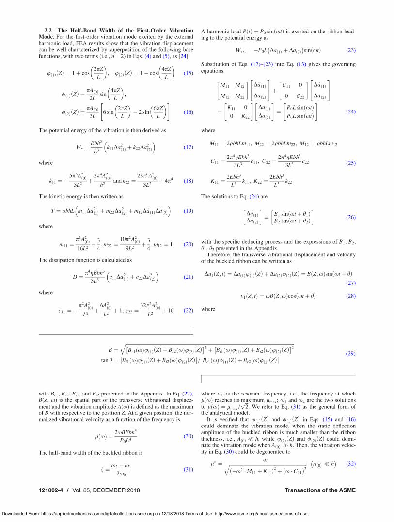
2.2 The Half-Band Width of the First-Order VibrationMode. For the first-order vibration mode excited by the externalharmonic load, FEA results show that the vibration displacementcan be well characterized by superposition of the following basefunctions, with two terms (i.e., n¼ 2) in Eqs. (4) and (5), as [24]:
u 1ð Þ Zð Þ ¼ 1þ cos2pZ
L
� �; u 2ð Þ Zð Þ ¼ 1� cos
4pZ
L
� �(15)
/ 1ð Þ Zð Þ ¼pA 0ð Þ
2Lsin
4pZ
L
� �;
/ 2ð Þ Zð Þ ¼pA 0ð Þ
3L6 sin
2pZ
L
� �� 2 sin
6pZ
L
� �" #(16)
The potential energy of the vibration is then derived as
Ws ¼Ebh3
L3k11Da2
1ð Þ þ k22Da22ð Þ
� �(17)
where
k11 ¼ �5p6A2
0ð Þ3L2
þ2p4A2
0ð Þh2
and k22 ¼28p6A2
0ð Þ3L2
þ 4p4 (18)
The kinetic energy is then written as
T ¼ qbhL m11D _a21ð Þ þ m22D _a2
2ð Þ þ m12D _a 1ð ÞD _a 2ð Þ� �
(19)
where
m11 ¼p2A2
0ð Þ16L2
þ 3
4;m22 ¼
10p2A20ð Þ
9L2þ 3
4;m12 ¼ 1 (20)
The dissipation function is calculated as
D ¼ p4gEbh3
3L3c11D _a2
1ð Þ þ c22D _a22ð Þ
� �(21)
where
c11 ¼ �p2A2
0ð ÞL2þ
6A20ð Þ
h2þ 1; c22 ¼
32p2A20ð Þ
L2þ 16 (22)
A harmonic load P tð Þ ¼ P0 sin xtð Þ is exerted on the ribbon lead-ing to the potential energy as
Wext ¼ �P0L Da 1ð Þ þ Da 2ð Þ� �
sin xtð Þ (23)
Substitution of Eqs. (17)–(23) into Eq. (13) gives the governingequations
M11 M12
M12 M22
" #D€a 1ð Þ
D€a 2ð Þ
24
35þ C11 0
0 C22
" #D _a 1ð Þ
D _a 2ð Þ
24
35
þK11 0
0 K22
" #Da 1ð Þ
Da 2ð Þ
" #¼
P0L sin xtð ÞP0L sin xtð Þ
" #(24)
where
M11 ¼ 2qbhLm11; M22 ¼ 2qbhLm22; M12 ¼ qbhLm12
C11 ¼2p4gEbh3
3L3c11; C22 ¼
2p4gEbh3
3L3c22
K11 ¼2Ebh3
L3k11; K22 ¼
2Ebh3
L3k22
(25)
The solutions to Eq. (24) are
Da 1ð ÞDa 2ð Þ
� �¼ B1 sin xtþ h1ð Þ
B2 sin xtþ h2ð Þ
� �(26)
with the specific deducing process and the expressions of B1, B2,h1, h2 presented in the Appendix.
Therefore, the transverse vibrational displacement and velocityof the buckled ribbon can be written as
Du1 Z; tð Þ ¼ Da 1ð Þu 1ð Þ Zð Þ þ Da 2ð Þu 2ð Þ Zð Þ ¼ B Z;xð Þsin xtþ hð Þ(27)
v1 Z; tð Þ ¼ xB Z;xð Þcos xtþ hð Þ (28)
where
B ¼ffiffiffiffiffiffiffiffiffiffiffiffiffiffiffiffiffiffiffiffiffiffiffiffiffiffiffiffiffiffiffiffiffiffiffiffiffiffiffiffiffiffiffiffiffiffiffiffiffiffiffiffiffiffiffiffiffiffiffiffiffiffiffiffiffiffiffiffiffiffiffiffiffiffiffiffiffiffiffiffiffiffiffiffiffiffiffiffiffiffiffiffiffiffiffiffiffiffiffiffiffiffiffiffiffiffiffiffiffiffiffiffiffiffiffiffiffiffiffiffiffiffiffiffiffiffiffiffiffiffiffiffiffiffiffiffiffiffiffiffiBr1 xð Þu 1ð Þ Zð Þ þ Br2 xð Þu 2ð Þ Zð Þ �2 þ Bi1 xð Þu 1ð Þ Zð Þ þ Bi2 xð Þu 2ð Þ Zð Þ
�2qtan h ¼ Bi1 xð Þu 1ð Þ Zð Þ þ Bi2 xð Þu 2ð Þ Zð Þ
�= Br1 xð Þu 1ð Þ Zð Þ þ Br2 xð Þu 2ð Þ Zð Þ � (29)
with Br1, Br2, Bi1, and Bi2 presented in the Appendix. In Eq. (27),B(Z, x) is the spatial part of the transverse vibrational displace-ment and the vibration amplitude A(x) is defined as the maximumof B with respective to the position Z. At a given position, the nor-malized vibrational velocity as a function of the frequency is
l xð Þ ¼ 2xBEbh3
P0L4(30)
The half-band width of the buckled ribbon is
n ¼ x2 � x1
2x0
(31)
where x0 is the resonant frequency, i.e., the frequency at whichl xð Þ reaches its maximum lmax; x1 and x2 are the two solutionsto l xð Þ ¼ lmax=
ffiffiffi2p
. We refer to Eq. (31) as the general form ofthe analytical model.
It is verified that u 1ð Þ Zð Þ and / 1ð Þ Zð Þ in Eqs. (15) and (16)could dominate the vibration mode, when the static deflectionamplitude of the buckled ribbon is much smaller than the ribbonthickness, i.e., A 0ð Þ � h, while u 2ð Þ Zð Þ and / 2ð Þ Zð Þ could domi-nate the vibration mode when A 0ð Þ � h. Then, the vibration veloc-ity in Eq. (30) could be degenerated to
l� ¼ xffiffiffiffiffiffiffiffiffiffiffiffiffiffiffiffiffiffiffiffiffiffiffiffiffiffiffiffiffiffiffiffiffiffiffiffiffiffiffiffiffiffiffiffiffiffiffiffiffiffiffiffiffiffiffiffiffiffiffiffiffiffiffiffi�x2 �M11 þ K11ð Þ2 þ x � C11ð Þ2
q A 0ð Þ � h� �
(32)
121002-4 / Vol. 85, DECEMBER 2018 Transactions of the ASME
Downloaded From: https://appliedmechanics.asmedigitalcollection.asme.org on 12/18/2018 Terms of Use: http://www.asme.org/about-asme/terms-of-use
l� ¼ xffiffiffiffiffiffiffiffiffiffiffiffiffiffiffiffiffiffiffiffiffiffiffiffiffiffiffiffiffiffiffiffiffiffiffiffiffiffiffiffiffiffiffiffiffiffiffiffiffiffiffiffiffiffiffiffiffiffiffiffiffiffiffiffi�x2 �M22 þ K22ð Þ2 þ x � C22ð Þ2
q A 0ð Þ � h� �
(33)
which lead to the half-band width
n� ¼ x2 � x1
2x0
¼ C11
2ffiffiffiffiffiffiffiffiffiffiffiffiffiffiffiM11K11
p ¼ p4gh
6L2
ffiffiffiE
q
sc11ffiffiffiffiffiffiffiffiffiffiffiffiffi
m11k11
p
¼ p4gx0
6
c11
k11
A 0ð Þ � h� �
(34)
n� ¼ x2 � x1
2x0
¼ C22
2ffiffiffiffiffiffiffiffiffiffiffiffiffiffiffiM22K22
p ¼ p4gh
6L2
ffiffiffiE
q
sc22ffiffiffiffiffiffiffiffiffiffiffiffiffi
m22k22
p
¼ p4gx0
6
c22
k22
A 0ð Þ � h� �
(35)
We refer to Eqs. (34) and (35) as the simplified form of the analyt-ical model for A 0ð Þ � h and A 0ð Þ � h, respectively.
2.3 The Extension of the Analytical Model to GeneralThree-Dimensional Structures. Since the 3D structures formedvia controlled buckling technique usually have a large staticdeflection amplitude, this paper focuses on the case whenA 0ð Þ � h. The half-band width of the buckled ribbon in Eq. (35)can be further written by using the relationship ecompre
¼ p2A20ð Þ=L2 1þ h2=3A2
0ð Þ
� �� p2A2
0ð Þ=L2, as
n�2 ¼p4gx0
6
c22
k22
¼ gx0n (36)
where n is the nondimensional half band width of the buckled rib-bon as
n ¼ p4
6
c22
k22
¼ 4ecompre þ 2
7ecompre þ 3(37)
By using the first-order Taylor expansion, the nondimensionalhalf-band width of the buckled ribbon demonstrated in Eq. (37)can be approximately written as
n � 2
31� 1
3ecompre
� �(38)
Inspired by the structure of the analytical solutions in Eqs. (36)and (38), the nondimensional half-band width n can be expressedin the form of scaling law by a single-variable function of thecompressive strain ecompre as
n ¼ a 1þ becompre
� �(39)
where a and b can be determined by fitting the FEA results of then ecompre curves. As we show in Sec. 3, the scaling law Eq. (39)applies to the vibration of a variety of 3D structures formed by thecompressive buckling technique with viscoelastic materials. Inaddition, it can be seen from Eq. (36) that this scaling law is inde-pendent of structural dimensions and material properties.
3 Examples and Discussions
The analytical model is validated by FEA, as presented inFig. 2. The FEA were performed using the commercial softwareABAQUS. The material was assumed to be a photopatternable epoxy
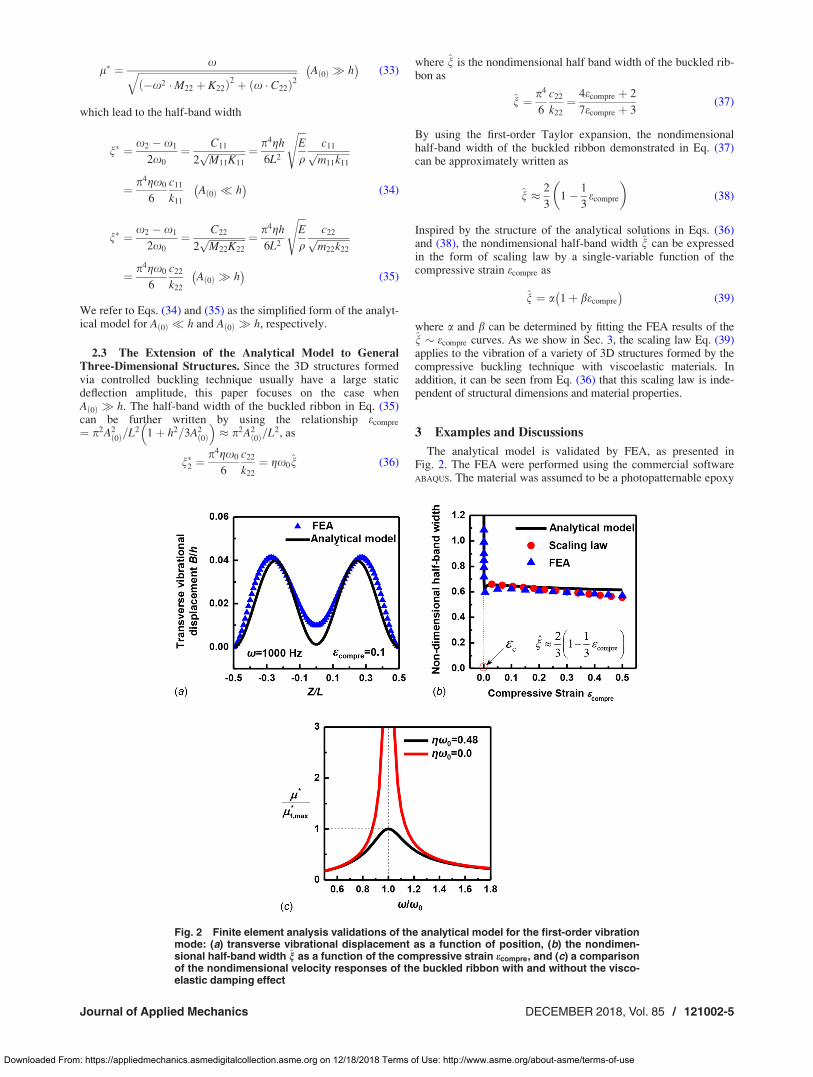
Fig. 2 Finite element analysis validations of the analytical model for the first-order vibrationmode: (a) transverse vibrational displacement as a function of position, (b) the nondimen-sional half-band width n as a function of the compressive strain ecompre, and (c) a comparisonof the nondimensional velocity responses of the buckled ribbon with and without the visco-elastic damping effect
Journal of Applied Mechanics DECEMBER 2018, Vol. 85 / 121002-5
Downloaded From: https://appliedmechanics.asmedigitalcollection.asme.org on 12/18/2018 Terms of Use: http://www.asme.org/about-asme/terms-of-use
(SU8), a typical polymer used in 3D assembly. The Young’s mod-ulus, Poisson’s ratio and density of SU8 are E¼ 4.02 GPa,�¼ 0.22, and q¼ 1.2 g/cm3 [24]. gx0 is assumed to be a constantto simulate the viscoelastic damping effect of Kelvin–Voigt modelbased on the data obtained by dynamic mechanical analysis, creepand stress relaxation, and other methods [49,53,54,75,76]. Thevibrational displacement and velocity under the harmonic externalload were obtained by the steady-state analysis, after importingthe shape and stress of the buckled ribbon determined from thepost-buckling analysis. The ribbon was discretized by Four-nodefinite-strain shell elements (S4) and at least 20 elements wereimplemented along the width direction of the ribbon to guaranteethe convergence.
Under a representative compressive strain ecompre ¼ 0:1, theanalytical results of the transverse vibrational displacement match
well with the FEA results, as shown in Fig. 2(a). Figure 2(b) givesa comparison of the nondimensional half-band width n calculatedby the general form of the analytical model (Eq. (31)), the scalinglaw (Eq. (38)), and FEA. The scaling law agrees well with FEAunder compressive strain ecompre > 0:05, a typical value used incompressive buckling techniques. The general form of the analyti-cal model agrees well with FEA in a broader range of compressivestrain ecompre, even when ecompre is close to the critical strain ec.Note that the nondimensional half-band width increases signifi-cantly when ecompre decreases to ec, which is consistent with thesimplified form of the analytical model for A 0ð Þ � h (Eq. (34)).Further, Fig. 2(c) plots a comparison of nondimensional velocityresponses of the buckled ribbon with and without the viscoelasticdamping effect. A obviously sharp peak of l�=l�1;maxx=x0
curve occurs at the natural frequency (x=x0 ¼ 1) for the casewithout the viscoelastic damping effect, where l�1;max representsthe maximum of velocity response with respect to the frequencywhen the viscoelastic damping effect is present.
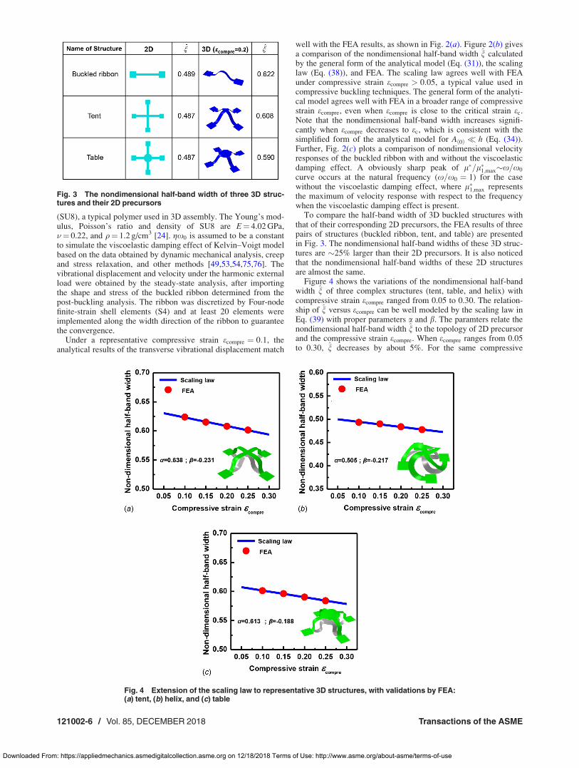
To compare the half-band width of 3D buckled structures withthat of their corresponding 2D precursors, the FEA results of threepairs of structures (buckled ribbon, tent, and table) are presentedin Fig. 3. The nondimensional half-band widths of these 3D struc-tures are 25% larger than their 2D precursors. It is also noticedthat the nondimensional half-band widths of these 2D structuresare almost the same.
Figure 4 shows the variations of the nondimensional half-bandwidth n of three complex structures (tent, table, and helix) withcompressive strain ecompre ranged from 0.05 to 0.30. The relation-ship of n versus ecompre can be well modeled by the scaling law inEq. (39) with proper parameters a and b. The paramters relate thenondimensional half-band width n to the topology of 2D precursorand the compressive strain ecompre. When ecompre ranges from 0.05to 0.30, n decreases by about 5%. For the same compressive
Fig. 3 The nondimensional half-band width of three 3D struc-tures and their 2D precursors
Fig. 4 Extension of the scaling law to representative 3D structures, with validations by FEA:(a) tent, (b) helix, and (c) table
121002-6 / Vol. 85, DECEMBER 2018 Transactions of the ASME
Downloaded From: https://appliedmechanics.asmedigitalcollection.asme.org on 12/18/2018 Terms of Use: http://www.asme.org/about-asme/terms-of-use
strain, the nondimensional half-band widths of the three structuresshow about 20% difference among each other. To further illustratethe relationship between n and the structure shape, we study more3D structures as shown in Figs. 5 and 6.
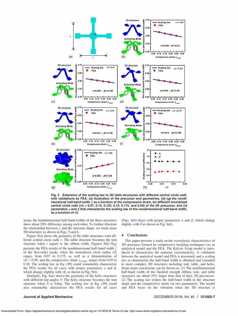
Figure 5(a) shows the geometry of the table structures with dif-ferent central circle radii r. The table structure becomes the tentstructure when r equals to the ribbon width. Figures 5(b)–5(g)
presents the FEA results of the nondimensional half-band width nof the first-order mode, when the normalized circle radius r/Lranges from 0.07 to 0.175, as well as a demonstration ofr/L¼ 0.50, and the compressive strain ecompre ranges from 0.05 to0.30. The scaling law in Eq. (39) could remarkably characterizethe FEA results for all cases with proper parameters a and b,which change slightly with r/L as shown in Fig. 5(h).
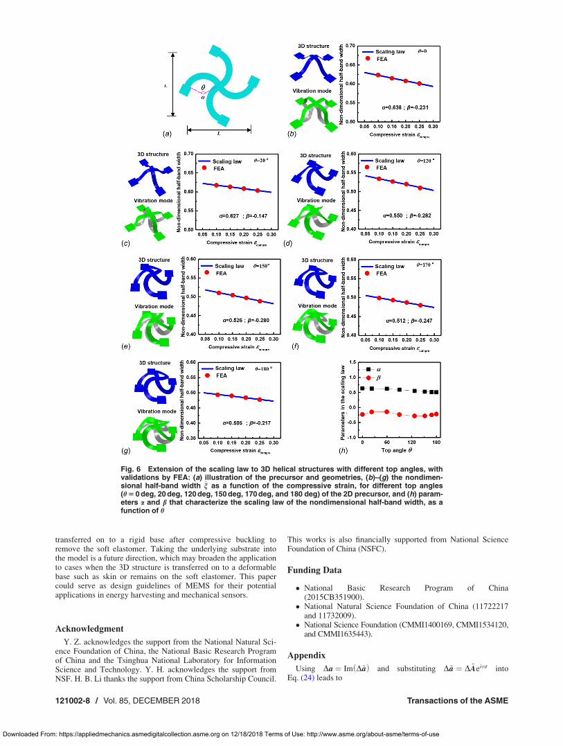
Similarly, Fig. 6(a) shows the geometry of the helix structureswith different top angles h. The helix structure becomes the tentstructure when h is 0 deg. The scaling law in Eq. (39) couldalso remarkably characterize the FEA results for all cases
(Figs. 6(b)–6(g)) with proper parameters a and b, which changeslightly with h as shown in Fig. 6(h).
4 Conclusions
This paper presents a study on the viscoelastic characteristics of3D structures formed by compressive buckling techniques via ananalytical model and the FEA. The Kelvin–Voigt model is intro-duced to characterize the material viscoelasticity. A validationbetween the analytical model and FEA is presented, and a scalinglaw to characterize the half-band width is obtained and extendedto more complex 3D structures including tent, table, and helix.Some main conclusions can be drawn as: (1) The nondimensionalhalf-band width of the buckled straight ribbon, tent, and tablestructures are about 25% larger than that of their 2D precursors.(2) The scaling law relates the half-band width to the structureshape and the compressive strain via two parameters. The modeland FEA focus on the vibration when the 3D structure is
Fig. 5 Extension of the scaling law to 3D table structures with different central circle radii,with validations by FEA: (a) illustration of the precursor and geometries, (b)–(g) the nondi-mensional half-band width n as a function of the compressive strain, for different normalizedcentral circle radii (r/L 5 0.07, 0.10, 0.125, 0.15, 0.175, and 0.50) of the 2D precursor, and (h)parameters a and b that characterize the scaling law of the nondimensional half-band width,as a function of r/L
Journal of Applied Mechanics DECEMBER 2018, Vol. 85 / 121002-7
Downloaded From: https://appliedmechanics.asmedigitalcollection.asme.org on 12/18/2018 Terms of Use: http://www.asme.org/about-asme/terms-of-use
transferred on to a rigid base after compressive buckling toremove the soft elastomer. Taking the underlying substrate intothe model is a future direction, which may broaden the applicationto cases when the 3D structure is transferred on to a deformablebase such as skin or remains on the soft elastomer. This papercould serve as design guidelines of MEMS for their potentialapplications in energy harvesting and mechanical sensors.
Acknowledgment
Y. Z. acknowledges the support from the National Natural Sci-ence Foundation of China, the National Basic Research Programof China and the Tsinghua National Laboratory for InformationScience and Technology. Y. H. acknowledges the support fromNSF. H. B. Li thanks the support from China Scholarship Council.
This works is also financially supported from National ScienceFoundation of China (NSFC).
Funding Data
National Basic Research Program of China(2015CB351900).
National Natural Science Foundation of China (11722217and 11732009).
National Science Foundation (CMMI1400169, CMMI1534120,and CMMI1635443).
Appendix
Using Da ¼ Im D~að Þ and substituting D~a ¼ D~Aeixt intoEq. (24) leads to
Fig. 6 Extension of the scaling law to 3D helical structures with different top angles, withvalidations by FEA: (a) illustration of the precursor and geometries, (b)–(g) the nondimen-sional half-band width n as a function of the compressive strain, for different top angles(h 5 0 deg, 20 deg, 120 deg, 150 deg, 170 deg, and 180 deg) of the 2D precursor, and (h) param-eters a and b that characterize the scaling law of the nondimensional half-band width, as afunction of h
121002-8 / Vol. 85, DECEMBER 2018 Transactions of the ASME
Downloaded From: https://appliedmechanics.asmedigitalcollection.asme.org on 12/18/2018 Terms of Use: http://www.asme.org/about-asme/terms-of-use
�x2M11 þ ixC11 þ K11 �x2M12
�x2M12 �x2M11 þ ixC22 þ K22
� �D ~A 1ð ÞD ~A 2ð Þ
" #
¼ MD~A ¼ P0LP0L
� �(A1)
Then, by multiplying the inverse coefficients matrix M�1 at bothsides of Eq. (A1), the solutions of D ~A 1ð Þ and D ~A 2ð Þ can beexpressed as
D ~A 1ð Þ ¼ Br1 þ iBi1; D ~A 2ð Þ ¼ Br2 þ iBi2 (A2)
where
Br1 ¼�P0L K22 þ M12 �M22ð Þx2
�T1 þ T2C22x
T2
1 þ T22
Bi1 ¼�P0L T1C22x� T2 K22 þ M12 �M22ð Þx2
� T2
1 þ T22
Br2 ¼�P0L K11 þ M12 �M11ð Þx2
�T1 þ T2C11x
T2
1 þ T22
Bi2 ¼�P0L T1C11x� T2 K11 þ M12 �M11ð Þx2
� T2
1 þ T22
(A3)
where
T1¼ M212�M11M22
� �x4þ K11M22þK22M11þC11C22ð Þx2�K11K22
T2¼ C11M22þC22M11ð Þx3� C11K22þC22K11ð Þx(A4)
Thereby, the solutions of Eq. (24) are obtained as
Da 1ð ÞDa 2ð Þ
� �¼ Im
D~a 1ð ÞD~a 2ð Þ
� �¼ B1 sin xtþ h1ð Þ
B2 sin xtþ h2ð Þ
� �(A5)
where, B1 ¼ffiffiffiffiffiffiffiffiffiffiffiffiffiffiffiffiffiffiB2
r1 þ B2i1
p, B2 ¼
ffiffiffiffiffiffiffiffiffiffiffiffiffiffiffiffiffiffiB2
r2 þ B2i2
p, tan h1 ¼ Bi1=Br1,
and tan h2 ¼ Bi2=Br2.
References[1] Feiner, R., Engel, L., Fleischer, S., Malki, M., Gal, I., Shapira, A., Shacham-
Diamand, Y., and Dvir, T., 2016, “Engineered Hybrid Cardiac Patches WithMultifunctional Electronics for Online Monitoring and Regulation of TissueFunction,” Nat. Mater., 15(6), pp. 679–685.
[2] Leong, T. G., Randall, C. L., Benson, B. R., Bassik, N., Stern, G. M., andGracias, D. H., 2009, “Tetherless Thermobiochemically ActuatedMicrogrippers,” Proc. Natl. Acad. Sci., 106(3), pp. 703–708.
[3] Tian, B., Liu, J., Dvir, T., Jin, L., Tsui, J. H., Qing, Q., Suo, Z., Langer, R.,Kohane, D. S., and Lieber, C. M., 2012, “Macroporous NanowireNanoelectronic Scaffolds for Synthetic Tissues,” Nat. Mater., 11(11), pp.986–994.
[4] Muth, J. T., Vogt, D. M., Truby, R. L., Meng€uc, Y., Kolesky, D. B., Wood, R.J., and Lewis, J. A., 2014, “Embedded 3D Printing of Strain Sensors WithinHighly Stretchable Elastomers,” Adv. Mater., 26(36), pp. 6307–6312.
[5] Gu, L., Tavakoli, M. M., Zhang, D., Zhang, Q., Waleed, A., Xiao, Y., Tsui, K.H., Lin, Y., Liao, L., Wang, J., and Fan, Z., 2016, “3D Arrays of 1024-PixelImage Sensors Based on Lead Halide Perovskite Nanowires,” Adv. Mater.,28(44), pp. 9713–9721.
[6] Li, X., Lin, Z.-H., Cheng, G., Wen, X., Liu, Y., Niu, S., and Wang, Z. L., 2014,“3D Fiber-Based Hybrid Nanogenerator for Energy Harvesting and as a Self-Powered Pressure Sensor,” ACS Nano, 8(10), pp. 10674–10681.
[7] Xu, L., Gutbrod, S. R., Bonifas, A. P., Su, Y., Sulkin, M. S., Lu, N., Chung,H.-J., Jang, K.-I., Liu, Z., Ying, M., Lu, C., Webb, C., Kim, J. S., Laughner, J.I., Cheng, H., Liu, Y., Ameen, A., Jeong, J. W., Kim, G. T., Huang, Y., Efimov,I. R., and Rogers, J. A., 2014, “3D Multifunctional Integumentary Membranesfor Spatiotemporal Cardiac Measurements and Stimulation Across the EntireEpicardium,” Nat. Commun., 5, p. 3329.
[8] Fan, Z., Razavi, H., Do, J-W., Moriwaki, A., Ergen, O., Chueh, Y.-L., Leu, P.W., Ho, J. C., Takahashi, T., and Reichertz, L. A., 2009, “Three-DimensionalNanopillar-Array Photovoltaics on Low-Cost and Flexible Substrates,” Nat.Mater., 8(8), pp. 648–653.
[9] Valentine, J., Zhang, S., Zentgraf, T., Ulin-Avila, E., Genov, D. A., Bartal, G.,and Zhang, X., 2008, “Three-Dimensional Optical Metamaterial With a Nega-tive Refractive Index,” Nature, 455(7211), pp. 376–379.
[10] Xiao, X., Zhou, W., Kim, Y., Ryu, I., Gu, M., Wang, C., Liu, G., Liu, Z., andGao, H., 2015, “Regulated Breathing Effect of Silicon Negative Electrode forDramatically Enhanced Performance of Li-Ion Battery,” Adv. Funct. Mater.,25(9), pp. 1426–1433.
[11] Sun, K., Wei, T. S., Ahn, B. Y., Seo, J. Y., Dillon, S. J., and Lewis, J. A., 2013,“3D Printing of Interdigitated Li-Ion Microbattery Architectures,” Adv. Mater.,25(33), pp. 4539–4543.
[12] Ning, H., Pikul, J. H., Zhang, R., Li, X., Xu, S., Wang, J., Rogers, J. A., King,W. P., and Braun, P. V., 2015, “Holographic Patterning of High-Performanceon-Chip 3D Lithium-Ion Microbatteries,” Proc. Natl. Acad. Sci., 112(21),pp. 6573–6578.
[13] Nawroth, J. C., Lee, H., Feinberg, A. W., Ripplinger, C. M., McCain, M. L.,Grosberg, A., Dabiri, J. O., and Parker, K. K., 2012, “A Tissue-Engineered Jel-lyfish With Biomimetic Propulsion,” Nat. Biotechnol., 30(8), pp. 792–797.
[14] Bartlett, N. W., Tolley, M. T., Overvelde, J. T., Weaver, J. C., Mosadegh, B.,Bertoldi, K., Whitesides, G. M., and Wood, R. J., 2015, “A 3D-Printed,Functionally Graded Soft Robot Powered by Combustion,” Science, 349(6244),pp. 161–165.
[15] Park, S.-J., Gazzola, M., Park, K. S., Park, S., Di Santo, V., Blevins, E. L.,Lind, J. U., Campbell, P. H., Dauth, S., Capulli, A. K., Pasqualini, F. S., Ahn,S., Cho, A., Yuan, H., Maoz, B. M., Vijaykumar, R., Choi, J. W., Deisseroth,K., Lauder, G. V., Mahadevan, L., and Parker, K. K., 2016, “PhototacticGuidance of a Tissue-Engineered Soft-Robotic Ray,” Science, 353(6295),pp. 158–162.
[16] Rogers, J., Huang, Y., Schmidt, O. G., and Gracias, D. H., 2016, “OrigamiMEMS and NEMS,” MRS Bull., 41(2), pp. 123–129.
[17] Liu, Y., Genzer, J., and Dickey, M. D., 2016, “2D or Not 2D”: Shape-Programming Polymer Sheets,” Prog. Polym. Sci., 52, pp. 79–106.
[18] Zou, H.-X., Zhang, W.-M., Wei, K.-X., Li, W.-B., Peng, Z.-K., and Meng, G.,2016, “A Compressive-Mode Wideband Vibration Energy Harvester Using aCombination of Bistable and Flextensional Mechanisms,” ASME J. Appl.Mech., 83(12), p. 121005.
[19] Li, W., Torres, D., D�ıaz, R., Wang, Z., Wu, C., Wang, C., Wang, Z. L., andSep�ulveda, N., 2017, “Nanogenerator-Based Dual-Functional and Self-PoweredThin Patch Loudspeaker or Microphone for Flexible Electronics,” Nat. Com-mun., 8, p. 15310.
[20] Bao, S., Wang, S., and Wang, B., 2017, “An Improved Fourier–Ritz Method forAnalyzing in-Plane Free Vibration of Sectorial Plates,” ASME J. Appl. Mech.,84(9), p. 091001.
[21] Yuan, J., Wei, X., and Huang, Y., 2017, “Exact Solutions for NonaxisymmetricVibrations of Radially Inhomogeneous Circular Mindlin Plates With VariableThickness,” ASME J. Appl. Mech., 84(7), p. 071003.
[22] Li, D., Zheng, Z. L., and Todd, M. D., 2018, “Nonlinear Vibration of Ortho-tropic Rectangular Membrane Structures Including Modal Coupling,” ASME J.Appl. Mech., 85(6), p. 061004.
[23] Mao, X.-Y., Ding, H., and Chen, L.-Q., 2017, “Vibration of Flexible StructuresUnder Nonlinear Boundary Conditions,” ASME J. Appl. Mech., 84(11),p. 111006.
[24] Wang, H., Ning, X., Li, H., Luan, H., Xue, Y., Yu, X., Fan, Z., Li, L., Rogers,J. A., Zhang, Y., and Huang, Y., 2018, “Vibration of Mechanically-Assembled3D Microstructures Formed by Compressive Buckling,” J. Mech. Phys. Solids,112, pp. 187–208.
[25] Xu, S., Yan, Z., Jang, K.-I., Huang, W., Fu, H., Kim, J., Wei, Z., Flavin, M.,McCracken, J., Wang, R., Badea, A., Liu, Y., Xiao, D., Zhou, G., Lee, J.,Chung, H. U., Cheng, H., Ren, W., Banks, A., Li, X., Paik, U., Nuzzo, R. G.,Huang, Y., Zhang, Y., and Rogers, J. A., 2015, “Assembly of Micro/Nanomaterials Into Complex, Three-Dimensional Architectures by Compres-sive Buckling,” Science, 347(6218), pp. 154–159.
[26] Zhang, Y., Yan, Z., Nan, K., Xiao, D., Liu, Y., Luan, H., Fu, H., Wang, X.,Yang, Q., Wang, J., Ren, W., Si, H., Liu, F., Yang, L., Li, H., Wang, J., Guo,X., Luo, H., Wang, L., Huang, Y., and Rogers, J. A., 2015, “A MechanicallyDriven Form of Kirigami as a Route to 3D Mesostructures in Micro/Nanomembranes,” Proc. Natl. Acad. Sci., 112(38), pp. 11757–11764.
[27] Fu, H., Nan, K., Bai, W., Huang, W., Bai, K., Lu, L., Zhou, C., Liu, Y., Liu, F.,Wang, J., Han, M., Yan, Z., Luan, H., Zhang, Y., Zhang, Y., Zhao, J., Cheng,X., Li, M., Lee, J. W., Liu, Y., Fang, D., Li, X., Huang, Y., Zhang, Y., and Rog-ers, J. A., 2018, “Morphable 3D Mesostructures and Microelectronic Devicesby Multistable Buckling Mechanics,” Nat. Mater., 17(3), pp. 268–276.
[28] Yan, Z., Zhang, F., Liu, F., Han, M., Ou, D., Liu, Y., Lin, Q., Guo, X., Fu, H.,Xie, Z., Gao, M., Huang, Y., Kim, J. H., Qiu, Y., Nan, K., Kim, J., Gutruf, P.,Luo, H., Zhao, A., Hwang, K. C., Huang, Y., Zhang, Y., and Rogers, J. A.,2016, “Mechanical Assembly of Complex, 3D Mesostructures From ReleasableMultilayers of Advanced Materials,” Sci. Adv., 2(9), p. e1601014.
[29] Zhang, Y., Zhang, F., Yan, Z., Ma, Q., Li, X., Huang, Y., and Rogers, J. A.,2017, “Printing, Folding and Assembly Methods for Forming 3D Mesostruc-tures in Advanced Materials,” Nat. Rev. Mater., 2(4), p. 17019.
[30] Danielson, C., Mehrnezhad, A., YekrangSafakar, A., and Park, K., 2017,“Fabrication and Characterization of Self-Folding Thermoplastic Sheets UsingUnbalanced Thermal Shrinkage,” Soft Matter, 13(23), pp. 4224–4230.
[31] Bauhofer, A. A., Kr€odel, S., Rys, J., Bilal, O. R., Constantinescu, A., and Dar-aio, C., 2017, “Harnessing Photochemical Shrinkage in Direct Laser Writingfor Shape Morphing of Polymer Sheets,” Adv. Mater., 29(42), p. 1703024.
[32] Cools, J., Jin, Q., Yoon, E., Burbano, D. A., Luo, Z., Cuypers, D., Callewaert,G., Braeken, D., and Gracias, D. H., 2018, “A Micropatterned Multielectrode
Journal of Applied Mechanics DECEMBER 2018, Vol. 85 / 121002-9
Downloaded From: https://appliedmechanics.asmedigitalcollection.asme.org on 12/18/2018 Terms of Use: http://www.asme.org/about-asme/terms-of-use
Shell for 3D Spatiotemporal Recording From Live Cells,” Adv. Sci., 5(4), p.1700731.
[33] Zhao, R., and Zhao, X., 2017, “Multimodal Surface Instabilities in CurvedFilm–Substrate Structures,” ASME J. Appl. Mech., 84(8), p. 081001.
[34] Auguste, A., Jin, L., Suo, Z., and Hayward, R. C., 2017, “Post-Wrinkle Bifurca-tions in Elastic Bilayers With Modest Contrast in Modulus,” Extreme Mech.Lett., 11, pp. 30–36.
[35] Liao, X., Xiao, J., Ni, Y., Li, C., and Chen, X., 2017, “Self-Assembly of Islandson Spherical Substrates by Surface Instability,” ACS Nano, 11(3), pp.2611–2617.
[36] Vinay, T. V., Banuprasad, T. N., George, S. D., Varghese, S., and Varanak-kottu, S. N., 2017, “Additive-Free Tunable Transport and Assembly of FloatingObjects at Water-Air Interface Using Bubble-Mediated Capillary Forces,” Adv.Mater. Interfaces, 4(7), p. 1601231.
[37] Hure, J., and Audoly, B., 2013, “Capillary Buckling of a Thin Film Adhering toa Sphere,” J. Mech. Phys. Solids, 61(2), pp. 450–471.
[38] Brubaker, N., and Lega, J., 2016, “Capillary-Induced Deformations of a ThinElastic Sheet,” Philos. Trans. R. Soc. London A, 374(2066), p. 20150169.
[39] Liu, C., Schauff, J., Joung, D., and Cho, J. H., 2017, “Remotely ControlledMicroscale 3D Self-Assembly Using Microwave Energy,” Adv. Mater. Tech-nol., 2(8), p. 1700035.
[40] Cui, J., Yao, S., Huang, Q., Adams, J. G., and Zhu, Y., 2017, “Controlling theSelf-Folding of a Polymer Sheet Using a Local Heater: The Effect of thePolymer–Heater Interface,” Soft Matter, 13(21), pp. 3863–3870.
[41] Xiuting, S., Zhang, S., Xu, J., and Wang, F., 2018, “Dynamical Analysis andRealization of an Adaptive Isolator,” ASME J. Appl. Mech., 85(1), p. 011002.
[42] Eichler, A., Moser, J., Chaste, J., Zdrojek, M., Wilson-Rae, I., and Bachtold,A., 2011, “Nonlinear Damping in Mechanical Resonators Made From CarbonNanotubes and Graphene,” Nat. Nanotechnol., 6(6), pp. 339–342.
[43] Unterreithmeier, Q. P., Faust, T., and Kotthaus, J. P., 2010, “Damping of Nano-mechanical Resonators,” Phys. Rev. Lett., 105(2), p. 027205.
[44] Louhghalam, A., Pellenq, R. J.-M., and Ulm, F.-J., 2018, “Thermalizing andDamping in Structural Dynamics,” ASME J. Appl. Mech., 85(8), p. 081001.
[45] Sun, T. L., Kurokawa, T., Kuroda, S., Ihsan, A. B., Akasaki, T., Sato, K.,Haque, M. A., Nakajima, T., and Gong, J. P., 2013, “Physical Hydrogels Com-posed of Polyampholytes Demonstrate High Toughness and Viscoelasticity,”Nat. Mater., 12(10), pp. 932–937.
[46] Khan, A. S., Lopez-Pamies, O., and Kazmi, R., 2006, “Thermo-MechanicalLarge Deformation Response and Constitutive Modeling of Viscoelastic Poly-mers Over a Wide Range of Strain Rates and Temperatures,” Int. J. Plasticity,22(4), pp. 581–601.
[47] Bauer, F., Denneler, S., and Willert-Porada, M., 2005, “Influence of Tempera-ture and Humidity on the Mechanical Properties of NafionVR 117 Polymer Elec-trolyte Membrane,” J. Polym. Sci. Part B: Polym. Phys., 43(7), pp. 786–795.
[48] Kim, B., Hopcroft, M. A., Candler, R. N., Jha, C. M., Agarwal, M., Melamud,R., Chandorkar, S. A., Yama, G., and Kenny, T. W., 2008, “TemperatureDependence of Quality Factor in MEMS Resonators,” J. Microelectromech.Syst., 17(3), pp. 755–766.
[49] Chung, S., and Park, S., 2013, “Effects of Temperature on Mechanical Propertiesof SU-8 Photoresist Material,” J. Mech. Sci. Technol., 27(9), pp. 2701–2707.
[50] Towler, B. W., Rupp, C. J., Cunningham, A. B., and Stoodley, P., 2003,“Viscoelastic Properties of a Mixed Culture Biofilm From Rheometer CreepAnalysis,” Biofouling, 19(5), pp. 279–285.
[51] Lu, B., Lamnawar, K., Maazouz, A., and Zhang, H., 2016, “Revealing theDynamic Heterogeneity of PMMA/PVDF Blends: From Microscopic Dynamicsto Macroscopic Properties,” Soft Matter, 12(13), pp. 3252–3264.
[52] Wouters, K., Gijsenbergh, P., and Puers, R., 2011, “Comparison of Methods forthe Mechanical Characterization of Polymers for MEMS Applications,” J.Micromech. Microeng., 21(11), p. 115027.
[53] Schiffmann, K. I., and Brill, C., 2007, “Testing the Viscoelastic Properties ofSU8 Photo Resist Thin Films at Different Stages of Processing by Nanoindenta-tion Creep and Stress Relaxation,” Int. J. Mater. Res., 98(5), pp. 397–403.
[54] Xu, T., Yoo, J. H., Babu, S., Roy, S., Lee, J.-B., and Lu, H., 2016,“Characterization of the Mechanical Behavior of SU-8 at Microscale by Visco-elastic Analysis,” J. Micromech. Microeng., 26(10), p. 105001.
[55] VanLandingham, M. R., Chang, N. K., Drzal, P., White, C. C., and Chang, S.H., 2005, “Viscoelastic Characterization of Polymers Using InstrumentedIndentation—Part I: Quasi-Static Testing,” J. Polym. Sci. Part B: Polym. Phys.,43(14), pp. 1794–1811.
[56] Jandak, M., Neuzil, T., Schneider, M., and Schmid, U., 2016, “Investigation onDifferent Damping Mechanisms on the Q Factor of MEMS Resonators,” Proce-dia Eng., 168, pp. 929–932.
[57] Torvik, P. J., 2011, “On Estimating System Damping From FrequencyResponse Bandwidths,” J. Sound Vib., 330(25), pp. 6088–6097.
[58] Fang, X., Chuang, K.-C., Jin, X., and Huang, Z., 2018, “Band-Gap Properties ofElastic Metamaterials With Inerter-Based Dynamic Vibration Absorbers,”ASME J. Appl. Mech., 85(7), p. 071010.
[59] Marynowski, K., 2002, “Non-Linear Dynamic Analysis of an Axialy MovingViscoelastic Beam,” J. Theor. Appl. Mech., 40(2), pp. 465–482.
[60] Arefi, M., and Zenkour, A. M., 2017, “Nonlocal Electro-Thermo-MechanicalAnalysis of a Sandwich Nanoplate Containing a Kelvin–Voigt ViscoelasticNanoplate and Two Piezoelectric Layers,” Acta Mech., 228(2), pp. 475–493.
[61] Rossikhin, Y. A., and Shitikova, M. V., 2011, “The Analysis of the ImpactResponse of a Thin Plate Via Fractional Derivative Standard Linear Solid Mod-el,” J. Sound Vib., 330(9), pp. 1985–2003.
[62] Ghayesh, M. H., 2012, “Nonlinear Dynamic Response of a Simply-SupportedKelvin–Voigt Viscoelastic Beam, Additionally Supported by a NonlinearSpring,” Nonlinear Anal.: Real World Appl., 13(3), pp. 1319–1333.
[63] Mahmoodi, S. N., Jalili, N., and Khadem, S. E., 2008, “An Experimental Inves-tigation of Nonlinear Vibration and Frequency Response Analysis of CantileverViscoelastic Beams,” J. Sound Vib., 311(3–5), pp. 1409–1419.
[64] Kolahchi, R., 2017, “A Comparative Study on the Bending, Vibration andBuckling of Viscoelastic Sandwich Nano-Plates Based on Different NonlocalTheories Using DC, HDQ and DQ Methods,” Aerosp. Sci. Technol., 66, pp.235–248.
[65] Tseng, W.-Y., and Dugundji, J., 1971, “Nonlinear Vibrations of aBuckled Beam Under Harmonic Excitation,” ASME J. Appl. Mech., 38(2), pp.467–476.
[66] Cottone, F., Gammaitoni, L., Vocca, H., Ferrari, M., and Ferrari, V., 2012,“Piezoelectric Buckled Beams for Random Vibration Energy Harvesting,”Smart Mater. Struct., 21(3), p. 035021.
[67] Yan, Z., Han, M., Shi, Y., Badea, A., Yang, Y., Kulkarni, A., Hanson, E.,Kandel, M. E., Wen, X., Zhang, F., Luo, Y., Lin, Q., Zhang, H., Guo, X.,Huang, Y., Nan, K., Jia, S., Oraham, A. W., Mevis, M. B., Lim, J., Guo, X.,Gao, M., Ryu, W., Yu, K. J., Nicolau, B. G., Petronico, A., Rubakjin, S. S.,Lou, J., Ajayan, P. M., Thornton, K., Popescu, G., Fang, D., Sweedler, J. V.,Braun, P. V., Zhang, H., Nuzzo, R. G., Huang, Y., Zhang, Y., and Rogers, J. A.,2017, “Three-Dimensional Mesostructures as High-Temperature Growth Tem-plates, Electronic Cellular Scaffolds, and Self-Propelled Microrobots,” Proc.Natl. Acad. Sci., 114(45), pp. E9455–E9464.
[68] Su, Y., Wu, J., Fan, Z., Hwang, K.-C., Song, J., Huang, Y., and Rogers, J. A.,2012, “Postbuckling Analysis and Its Application to Stretchable Electronics,” J.Mech. Phys. Solids, 60(3), pp. 487–508.
[69] Fan, Z., Zhang, Y., Ma, Q., Zhang, F., Fu, H., Hwang, K.-C., and Huang, Y.,2016, “A Finite Deformation Model of Planar Serpentine Interconnects forStretchable Electronics,” Int. J. Solids Struct., 91, pp. 46–54.
[70] Fan, Z., Wu, J., Ma, Q., Liu, Y., Su, Y., and Hwang, K.-C., 2017, “Post-Buckling Analysis of Curved Beams,” ASME J. Appl. Mech., 84(3), p. 031007.
[71] Fan, Z., Hwang, K.-C., Rogers, J. A., Huang, Y., and Zhang, Y., 2018, “A Dou-ble Perturbation Method of Postbuckling Analysis in 2D Curved Beams forAssembly of 3D Ribbon-Shaped Structures,” J. Mech. Phys. Solids, 111,pp. 215–238.
[72] Ko, H. C., Shin, G., Wang, S., Stoykovich, M. P., Lee, J. W., Kim, D. H., Ha, J.S., Huang, Y., Hwang, K. C., and Rogers, J. A., 2009, “Curvilinear ElectronicsFormed Using Silicon Membrane Circuits and Elastomeric Transfer Elements,”Small, 5(23), pp. 2703–2709.
[73] Zhu, L., and Chen, X., 2017, “Delamination-Based Measurement and Predic-tion of the Adhesion Energy of Thin Film/Substrate Interfaces,” J. Eng. Mater.Technol., 139(2), p. 021021.
[74] Simsek, M., and Kocat€urk, T., 2009, “Nonlinear Dynamic Analysis of anEccentrically Prestressed Damped Beam Under a Concentrated Moving Har-monic Load,” J. Sound Vib., 320(1–2), pp. 235–253.
[75] Schoeberle, B., Wendlandt, M., and Hierold, C., 2008, “Long-Term CreepBehavior of SU-8 Membranes: Application of the Time–Stress SuperpositionPrinciple to Determine the Master Creep Compliance Curve,” Sens. ActuatorsA: Phys., 142(1), pp. 242–249.
[76] Banks, H. T., and Inman, D., 1991, “On Damping Mechanisms in Beams,”ASME J. Appl. Mech., 58(3), pp. 716–723.
121002-10 / Vol. 85, DECEMBER 2018 Transactions of the ASME
Downloaded From: https://appliedmechanics.asmedigitalcollection.asme.org on 12/18/2018 Terms of Use: http://www.asme.org/about-asme/terms-of-use