vision-based autonomous quadrotor landing on a moving …rpg.ifi.uzh.ch/docs/ssrr17_falanga.pdf ·...
TRANSCRIPT
Vision-based Autonomous Quadrotor Landing on a Moving Platform
Davide Falanga, Alessio Zanchettin, Alessandro Simovic, Jeffrey Delmerico, and Davide Scaramuzza
Abstract— We present a quadrotor system capable of au-tonomously landing on a moving platform using only onboardsensing and computing. We rely on state-of-the-art computervision algorithms, multi-sensor fusion for localization of therobot, detection and motion estimation of the moving platform,and path planning for fully autonomous navigation. Our systemdoes not require any external infrastructure, such as motion-capture systems. No prior information about the location ofthe moving landing target is needed. We validate our system inboth synthetic and real-world experiments using low-cost andlightweight consumer hardware. To the best of our knowledge,this is the first demonstration of a fully autonomous quadrotorsystem capable of landing on a moving target, using only on-board sensing and computing, without relying on any externalinfrastructure.
SUPPLEMENTARY MATERIAL
Video of the experiments: https://youtu.be/
Tz5ubwoAfNE
I. INTRODUCTION
Quadrotors are highly agile and versatile flying robots.Recent work has demonstrated their capabilities in manydifferent applications including but not limited to: search-and-rescue, object transportation, inspection, surveillanceand mapping [1], [2], [3]. The drawback of multirotorsin general is a lower efficiency of the propulsion systemwhen compared to other aerial vehicles, such as fixed-wingaircrafts. This limits the autonomy and utility of quadrotorsas the time during which the vehicle can remain airborne isrelatively short. One possible solution is to have a quadrotorautonomously land on a ground-station where its battery ischarged or replaced.
Search and rescue robotics is a domain that could greatlybenefit from aerial robots capable of landing autonomouslyon moving platforms. One day, flying robots will assistrescuers during their missions by providing an optimal plat-form for aerial inspection and mapping of the surroundings.Allowing these vehicles to autonomously land on predefinedtargets for battery charging/swapping or delivery of supplieswould drastically enhance their usefulness while requiringlimited or no human intervention. This would representa major step forward in the use of autonomous robotsin search-and-rescue missions, whose duration is usuallysignificantly longer then the typical flight time of a drone.
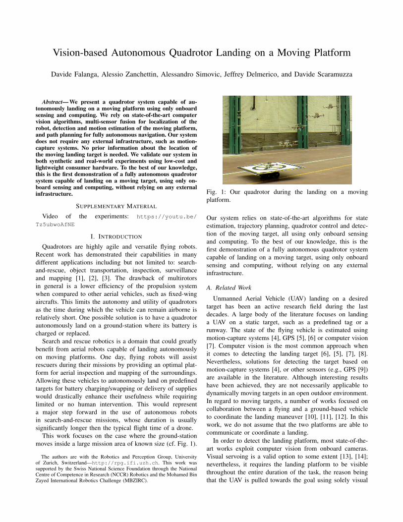
This work focuses on the case where the ground-stationmoves inside a large mission area of known size (cf. Fig. 1).
The authors are with the Robotics and Perception Group, Universityof Zurich, Switzerland—http://rpg.ifi.uzh.ch. This work wassupported by the Swiss National Science Foundation through the NationalCentre of Competence in Research (NCCR) Robotics and the Mohamed BinZayed International Robotics Challenge (MBZIRC).
Fig. 1: Our quadrotor during the landing on a movingplatform.
Our system relies on state-of-the-art algorithms for stateestimation, trajectory planning, quadrotor control and detec-tion of the moving target, all using only onboard sensingand computing. To the best of our knowledge, this is thefirst demonstration of a fully autonomous quadrotor systemcapable of landing on a moving target, using only onboardsensing and computing, without relying on any externalinfrastructure.
A. Related Work
Unmanned Aerial Vehicle (UAV) landing on a desiredtarget has been an active research field during the lastdecades. A large body of the literature focuses on landinga UAV on a static target, such as a predefined tag or arunway. The state of the flying vehicle is estimated usingmotion-capture systems [4], GPS [5], [6] or computer vision[7]. Computer vision is the most common approach whenit comes to detecting the landing target [6], [5], [7], [8].Nevertheless, solutions for detecting the target based onmotion-capture systems [4], or other sensors (e.g., GPS [9])are available in the literature. Although interesting resultshave been achieved, they are not necessarily applicable todynamically moving targets in an open outdoor environment.In regard to moving targets, a number of works focused oncollaboration between a flying and a ground-based vehicleto coordinate the landing maneuver [10], [11], [12]. In thiswork, we do not assume that the two platforms are able tocommunicate or coordinate a landing.
In order to detect the landing platform, most state-of-the-art works exploit computer vision from onboard cameras.Visual servoing is a valid option to some extent [13], [14];nevertheless, it requires the landing platform to be visiblethroughout the entire duration of the task, the reason beingthat the UAV is pulled towards the goal using solely visual
information from its camera. To deal with missing visualinformation, model-based approaches have been proposed topredict the motion of the landing target [15], [16]. Alternativesolutions are realized with the use of additional sensorsattached to the moving target. Among many, these sensorsinclude Inertial Measurement Units (IMU), GPS receivers[11], [17] or infrared markers [18].
For the UAV to be truly autonomous, all of the com-putation necessary to achieve the goal must be performedonboard. This is by no means standard in the literature, sinceall the approaches mentioned before rely on external compu-tation for state estimation, trajectory planning or control [13],[15], [16]. Additionally, GPS [9], [19], [11], [16] or motion-capture systems [13], [12] are often used for state estimation,either only while patrolling or throughout the entire task.Conversely, we rely only on onboard visual-inertial odometryfor state estimation.
B. Contribution
In this paper, we present a quadrotor system capableof autonomously landing on a moving target using onlyonboard sensing and computing. No prior knowledge aboutthe location of the moving landing target is needed. Weexploit state-of-the-art visual-inertial odometry to estimatethe state of the quadrotor itself, complemented by nonlinearcontrol algorithms to drive the vehicle. Our system detectsthe landing target using an onboard camera and deals withtemporarily missing visual information by exploiting the thetarget’s dynamical model. Therefore, no external infrastruc-ture such as a motion-capture system is needed. We computetrajectories that take into account the dynamical model ofthe quadrotor and are optimal with respect to a cost functionbased on the energy necessary to execute it. We validate ourapproach in simulation as well as in real-world experiments,using low-cost, lightweight consumer hardware.
The remainder of this paper is structured as follows:Sec. II provides an overview on the proposed frameworkand details the algorithms used to estimate the state ofthe quadrotor, detect and track the moving platform, plantrajectories for the aerial vehicle, and control it along thesetrajectories. Sec. III describes the experimental platform andthe simulation tools used to validate our approach, andprovides the experimental results. In Sec. IV, we discuss theproposed method and provide insights on the experiments.Finally, we draw conclusions in Sec. V.
II. SYSTEM OVERVIEW
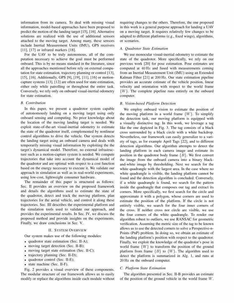
Our system makes use of the following modules:• quadrotor state estimation (Sec. II-A);• moving target detection (Sec. II-B);• moving target state estimation (Sec. II-C);• trajectory planning (Sec. II-D);• quadrotor control (Sec. II-E);• state machine (Sec. II-F).Fig. 2 provides a visual overview of these components.
The modular structure of our framework allows us to easilymodify or replace the algorithms inside each module without
requiring changes to the others. Therefore, the one proposedin this work is a general purpose approach for landing a UAVon a moving target. It requires relatively few changes to beadapted to different platforms (e.g., fixed wings), algorithms,or scenarios.
A. Quadrotor State Estimation
We use monocular visual-inertial odometry to estimate thestate of the quadrotor. More specifically, we rely on ourprevious work [20] for pose estimation. Pose estimates arecomputed at 40Hz and fused with measurements comingfrom an Inertial Measurement Unit (IMU) using an ExtendedKalman Filter [21] at 200Hz. Our state estimation pipelineprovides an accurate estimate of the vehicle position, linearvelocity and orientation with respect to the world frame{W}. The complete pipeline runs entirely on the onboardcomputer.
B. Vision-based Platform Detection
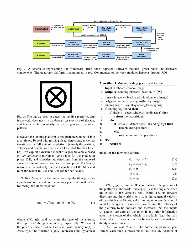
We employ onboard vision to estimate the position ofthe moving platform in a world frame {W}. To simplifythe detection task, our moving platform is equipped witha visually distinctive tag. In this work, we leverage a taglike the one depicted in Fig. 3. The tag consists of a blackcross surrounded by a black circle with a white backdrop.Nevertheless, our framework can easily generalize to a vari-ety of tags, as for example April Tags [22], and to differentdetection algorithms. Our algorithm attempts to detect thelanding platform in each camera image and estimate itsposition in the quadrotor body frame {B}. We first convertthe image from the onboard camera into a binary black-and-white image by thresholding. Next we search for thewhite quadrangle with the largest area. In the case where nowhite quadrangle is visible, the landing platform cannot befound and the detection algorithm is concluded. Conversely,if a white quadrangle is found, we search for the patterninside the quadrangle that composes our tag and extract itscorners. More specifically, we first search for the circle andapproximate it with a polygon, whose corners are used toestimate the position of the platform. If the circle is notentirely visible, we search for the four inner corners ofthe cross. If neither cross nor circle are visible, we usethe four corners of the white quadrangle. To render ouralgorithm robust to outliers, we use RANSAC for geometricverification. Assuming the metric size of the tag to be knownallows us to use the detected corners to solve a Perspective-n-Points (PnP) problem. In doing so, we obtain an estimate ofthe landing platform’s position with respect to the quadrotor.Finally, we exploit the knowledge of the quadrotor’s pose inworld frame {W} to transform the position of the groundplatform from frame {B} to {W}. The algorithm used todetect the platform is summarized in Alg. 1, and runs at20Hz on the onboard computer.
C. Platform State Estimation
The algorithm presented in Sec. II-B provides an estimateof the position of the ground vehicle in the world frame W .
SENSORFUSION
AUTOPILOT
VISUALODOMETRY
CAMERA
CAMERA PLATFORM DETECTION
KALMANFILTER
TRAJECTORYPLANNING
HIGH-LEVELCONTROL
STATEMACHINE
QUADROTOR
Quadrotor Desired State
(50 Hz)
Predicted Platform State (50 Hz)
Platform PoseEstimate (20 Hz)
Quadrotor PoseEstimate (40 Hz)
Quadrotor State Estimate(200 Hz)
Inertial Measurements (200Hz)
Single Rotor Thrusts (200 Hz)
Desired Bodyrates (50 Hz)
Image (40 Hz)
LOW-LEVELCONTROL
Desired Torques (200 Hz)
Platform State Estimate(200 Hz)
Desired Collective Thrust (50 Hz)
Image (40 Hz)
Fig. 2: A schematic representing our framework. Blue boxes represent software modules, green boxes are hardwarecomponents. The quadrotor platform is represented in red. Communication between modules happens through ROS.
Fig. 3: The tag we used to detect the landing platform. Ourframework does not strictly depend on specifics of the tag,and thanks to its modularity can easily generalize to otherpatterns.
However, the landing platform is not guaranteed to be visibleat all times. To deal with missing visual detections, as well asto estimate the full state of the platform (namely the position,velocity and orientation), we use an Extended Kalman Filter[23]. We exploit a dynamic model of a ground vehicle basedon non-holonomic movement constraints for the predictionphase [24], and consider tag detections from the onboardcamera as measurements for the correction phase. For brevityreasons, we report only the main equations of the filter andrefer the reader to [23] and [25] for further details.
1) Time Update: In the prediction step, the filter providesa prediction of the state of the moving platform based on thefollowing non-linear equation:
x(t) = f(x(t),u(t)) +w(t), (1)
where x(t), u(t) and w(t) are the state of the system,the input and the process noise, respectively. We modelthe process noise as white Gaussian noise, namely w(t) ∼N (0, σ2
w). The function f(x,u) represents the dynamical
Algorithm 1 Moving landing platform detection
1: Input: Onboard camera image2: Outputs: Landing platform position in {W}3: binary image ← black and white(camera image)4: polygons ← detect polygons(binary image)5: landing tag ← largest quadrangle(polygons)6: if landing tag found then7: if circle ← detect circle in(landing tag) then8: return circle.position()9: else
10: if cross ← detect cross in(landing tag) then11: return cross.position()12: else13: return landing tag.position()14: else15: return 0
model of the moving platform:
px = vt cos(θ) (2a)py = vt sin(θ) (2b)pz = 0 (2c)
θ = u1 (2d)vt = u2 (2e)
In (2), px, py, pz are the 3D coordinates of the position ofthe platform in the world frame {W}, θ is the angle betweenthe x-axis of the vehicle’s body frame (i.e., its forwarddirection) and the world x-axis, vt is the tangential velocityof the vehicle (see Fig.4), and u1 and u2 represent the controlinput to the system. In our case, we assume the velocity ofthe platform to be constant and therefore, that the inputsu1 and u2 are zero all the time. If any prior informationabout the motion of the vehicle is available (e.g., the pathalong which it moves), this can be easily incorporated intothe dynamical model.
2) Measurement Update: The correction phase is per-formed each time a measurement zk (the 3D position of
?
v t
p = (px,py,pz)
yp xp
zp{P
}
yw
xwzw
{W}
Fig. 4: A schematics representing the dynamical model ofthe moving platform. The world frame is indicated as {W},while the platform body frame as {P}.
the moving platform) is provided by the detection algorithm,according to the following equations:
ˆx(t) = f(x(t),u(t)) +K(t)(z(t)− h(x(t)), (3)
where the matrix K(t) represents the Kalman gain.
D. Trajectory Planning
We use the approach proposed in [26] to plan optimal,feasible trajectories that prevent the vehicle from collidingwith obstacles. The authors of that work propose a fastpolynomial trajectory generation method that minimizes thethird derivative of the position (namely, the jerk). Such anapproach solves the minimization problem in closed form,therefore it is able to provide an optimal trajectory withina few micro-seconds running entirely onboard. Furthermore,the same method provides tools to verify whether the plannedtrajectory is feasible or not. More specifically, it allows thesystem to quickly check that each candidate: (i) does notexceed the physical actuation constraints of the platform,and (ii) does not collide with known obstacles (e.g., withthe ground).
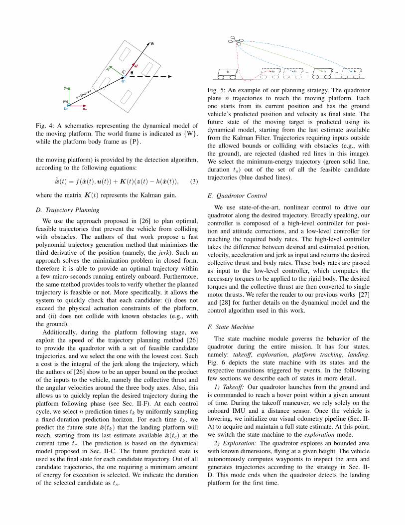
Additionally, during the platform following stage, weexploit the speed of the trajectory planning method [26]to provide the quadrotor with a set of feasible candidatetrajectories, and we select the one with the lowest cost. Sucha cost is the integral of the jerk along the trajectory, whichthe authors of [26] show to be an upper bound on the productof the inputs to the vehicle, namely the collective thrust andthe angular velocities around the three body axes. Also, thisallows us to quickly replan the desired trajectory during theplatform following phase (see Sec. II-F). At each controlcycle, we select n prediction times tk by uniformly samplinga fixed-duration prediction horizon. For each time tk, wepredict the future state x(tk) that the landing platform willreach, starting from its last estimate available x(tc) at thecurrent time tc. The prediction is based on the dynamicalmodel proposed in Sec. II-C. The future predicted state isused as the final state for each candidate trajectory. Out of allcandidate trajectories, the one requiring a minimum amountof energy for execution is selected. We indicate the durationof the selected candidate as ts.
tc ts tn... ...t1t0
Fig. 5: An example of our planning strategy. The quadrotorplans n trajectories to reach the moving platform. Eachone starts from its current position and has the groundvehicle’s predicted position and velocity as final state. Thefuture state of the moving target is predicted using itsdynamical model, starting from the last estimate availablefrom the Kalman Filter. Trajectories requiring inputs outsidethe allowed bounds or colliding with obstacles (e.g., withthe ground), are rejected (dashed red lines in this image).We select the minimum-energy trajectory (green solid line,duration ts) out of the set of all the feasible candidatetrajectories (blue dashed lines).
E. Quadrotor Control
We use state-of-the-art, nonlinear control to drive ourquadrotor along the desired trajectory. Broadly speaking, ourcontroller is composed of a high-level controller for posi-tion and attitude corrections, and a low-level controller forreaching the required body rates. The high-level controllertakes the difference between desired and estimated position,velocity, acceleration and jerk as input and returns the desiredcollective thrust and body rates. These body rates are passedas input to the low-level controller, which computes thenecessary torques to be applied to the rigid body. The desiredtorques and the collective thrust are then converted to singlemotor thrusts. We refer the reader to our previous works [27]and [28] for further details on the dynamical model and thecontrol algorithm used in this work.
F. State Machine
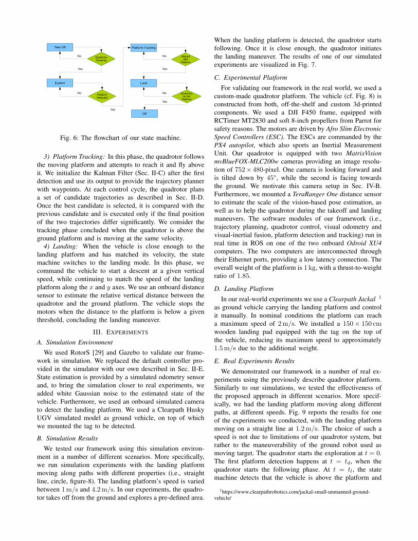
The state machine module governs the behavior of thequadrotor during the entire mission. It has four states,namely: takeoff, exploration, platform tracking, landing.Fig. 6 depicts the state machine with its states and therespective transitions triggered by events. In the followingfew sections we describe each of states in more detail.
1) Takeoff: Our quadrotor launches from the ground andis commanded to reach a hover point within a given amountof time. During the takeoff maneuver, we rely solely on theonboard IMU and a distance sensor. Once the vehicle ishovering, we initialize our visual odometry pipeline (Sec. II-A) to acquire and maintain a full state estimate. At this point,we switch the state machine to the exploration mode.
2) Exploration: The quadrotor explores an bounded areawith known dimensions, flying at a given height. The vehicleautonomously computes waypoints to inspect the area andgenerates trajectories according to the strategy in Sec. II-D. This mode ends when the quadrotor detects the landingplatform for the first time.
Take Off
Explore
QuadrotorHovering
Platform Tracking
PlatformDetected
Land
Alignedwith
Platform
Off
Quadrotoron the
Platform
QuadrotorHovering
No
No No
No
Yes
Yes
Yes
Yes
Fig. 6: The flowchart of our state machine.
3) Platform Tracking: In this phase, the quadrotor followsthe moving platform and attempts to reach it and fly aboveit. We initialize the Kalman Filter (Sec. II-C) after the firstdetection and use its output to provide the trajectory plannerwith waypoints. At each control cycle, the quadrotor plansa set of candidate trajectories as described in Sec. II-D.Once the best candidate is selected, it is compared with theprevious candidate and is executed only if the final positionof the two trajectories differ significantly. We consider thetracking phase concluded when the quadrotor is above theground platform and is moving at the same velocity.
4) Landing: When the vehicle is close enough to thelanding platform and has matched its velocity, the statemachine switches to the landing mode. In this phase, wecommand the vehicle to start a descent at a given verticalspeed, while continuing to match the speed of the landingplatform along the x and y axes. We use an onboard distancesensor to estimate the relative vertical distance between thequadrotor and the ground platform. The vehicle stops themotors when the distance to the platform is below a giventhreshold, concluding the landing maneuver.
III. EXPERIMENTS
A. Simulation Environment
We used RotorS [29] and Gazebo to validate our frame-work in simulation. We replaced the default controller pro-vided in the simulator with our own described in Sec. II-E.State estimation is provided by a simulated odometry sensorand, to bring the simulation closer to real experiments, weadded white Gaussian noise to the estimated state of thevehicle. Furthermore, we used an onboard simulated camerato detect the landing platform. We used a Clearpath HuskyUGV simulated model as ground vehicle, on top of whichwe mounted the tag to be detected.
B. Simulation Results
We tested our framework using this simulation environ-ment in a number of different scenarios. More specifically,we run simulation experiments with the landing platformmoving along paths with different properties (i.e., straightline, circle, figure-8). The landing platform’s speed is variedbetween 1m/s and 4.2m/s. In our experiments, the quadro-tor takes off from the ground and explores a pre-defined area.
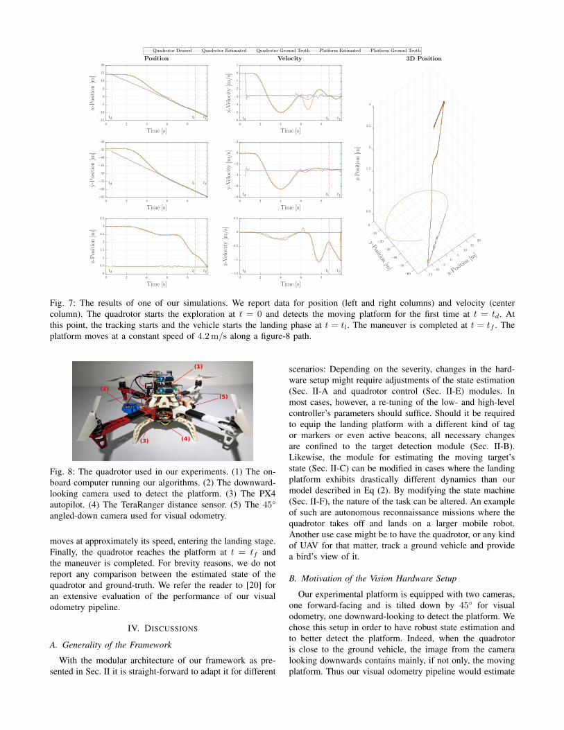
When the landing platform is detected, the quadrotor startsfollowing. Once it is close enough, the quadrotor initiatesthe landing maneuver. The results of one of our simulatedexperiments are visualized in Fig. 7.
C. Experimental Platform
For validating our framework in the real world, we used acustom-made quadrotor platform. The vehicle (cf. Fig. 8) isconstructed from both, off-the-shelf and custom 3d-printedcomponents. We used a DJI F450 frame, equipped withRCTimer MT2830 and soft 8-inch propellers from Parrot forsafety reasons. The motors are driven by Afro Slim ElectronicSpeed Controllers (ESC). The ESCs are commanded by thePX4 autopilot, which also sports an Inertial MeasurementUnit. Our quadrotor is equipped with two MatrixVisionmvBlueFOX-MLC200w cameras providing an image resolu-tion of 752× 480-pixel. One camera is looking forward andis tilted down by 45°, while the second is facing towardsthe ground. We motivate this camera setup in Sec. IV-B.Furthermore, we mounted a TeraRanger One distance sensorto estimate the scale of the vision-based pose estimation, aswell as to help the quadrotor during the takeoff and landingmaneuvers. The software modules of our framework (i.e.,trajectory planning, quadrotor control, visual odometry andvisual-inertial fusion, platform detection and tracking) run inreal time in ROS on one of the two onboard Odroid XU4computers. The two computers are interconnected throughtheir Ethernet ports, providing a low latency connection. Theoverall weight of the platform is 1 kg, with a thrust-to-weightratio of 1.85.
D. Landing Platform
In our real-world experiments we use a Clearpath Jackal 1
as ground vehicle carrying the landing platform and controlit manually. In nominal conditions the platform can reacha maximum speed of 2m/s. We installed a 150× 150 cmwooden landing pad equipped with the tag on the top ofthe vehicle, reducing its maximum speed to approximately1.5m/s due to the additional weight.
E. Real Experiments Results
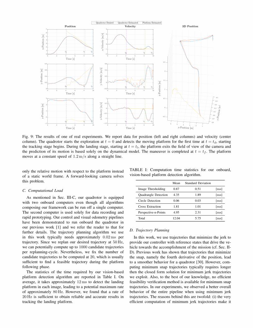
We demonstrated our framework in a number of real ex-periments using the previously describe quadrotor platform.Similarly to our simulations, we tested the effectiveness ofthe proposed approach in different scenarios. More specif-ically, we had the landing platform moving along differentpaths, at different speeds. Fig. 9 reports the results for oneof the experiments we conducted, with the landing platformmoving on a straight line at 1.2m/s. The choice of such aspeed is not due to limitations of our quadrotor system, butrather to the maneuverability of the ground robot used asmoving target. The quadrotor starts the exploration at t = 0.The first platform detection happens at t = td, when thequadrotor starts the following phase. At t = tl, the statemachine detects that the vehicle is above the platform and
1https://www.clearpathrobotics.com/jackal-small-unmanned-ground-vehicle/
tftltd
tftltd
tftltd
tftltd
tftltd
tftltd
x-Position [m]
y-Position[m]
z-Position[m
]
Time [s]
z-Velocity[m
/s]
Time [s]
y-Velocity[m
/s]
Time [s]
x-Velocity[m
/s]
Time [s]
z-Position[m
]
Time [s]
y-Position[m
]
Time [s]
x-Position[m
]
3D PositionVelocityPosition
−15
−10
−5
0
5
10
15
20
0 2 4 6 8
0 2 4 6 8
0 2 4 6 8
0 2 4 6 8
0 2 4 6 8
0 2 4 6 8
−60
−50
−40
−30
−20
−10
0
−1.5
−1
−0.5
0
0.5
−8
−6
−4
−2
0
2
−6
−5
−4
−3
−2
−1
0
1
0
0.5
1
1.5
2
2.5
3
3.5
−65
−60
−55
−50
−45
−40
−35
−30
−15
−10
−5
0
5
10
15
20
0.5
1
1.5
2
2.5
3
Fig. 7: The results of one of our simulations. We report data for position (left and right columns) and velocity (centercolumn). The quadrotor starts the exploration at t = 0 and detects the moving platform for the first time at t = td. Atthis point, the tracking starts and the vehicle starts the landing phase at t = tl. The maneuver is completed at t = tf . Theplatform moves at a constant speed of 4.2m/s along a figure-8 path.
Fig. 8: The quadrotor used in our experiments. (1) The on-board computer running our algorithms. (2) The downward-looking camera used to detect the platform. (3) The PX4autopilot. (4) The TeraRanger distance sensor. (5) The 45°angled-down camera used for visual odometry.
moves at approximately its speed, entering the landing stage.Finally, the quadrotor reaches the platform at t = tf andthe maneuver is completed. For brevity reasons, we do notreport any comparison between the estimated state of thequadrotor and ground-truth. We refer the reader to [20] foran extensive evaluation of the performance of our visualodometry pipeline.
IV. DISCUSSIONS
A. Generality of the Framework
With the modular architecture of our framework as pre-sented in Sec. II it is straight-forward to adapt it for different
scenarios: Depending on the severity, changes in the hard-ware setup might require adjustments of the state estimation(Sec. II-A and quadrotor control (Sec. II-E) modules. Inmost cases, however, a re-tuning of the low- and high-levelcontroller’s parameters should suffice. Should it be requiredto equip the landing platform with a different kind of tagor markers or even active beacons, all necessary changesare confined to the target detection module (Sec. II-B).Likewise, the module for estimating the moving target’sstate (Sec. II-C) can be modified in cases where the landingplatform exhibits drastically different dynamics than ourmodel described in Eq (2). By modifying the state machine(Sec. II-F), the nature of the task can be altered. An exampleof such are autonomous reconnaissance missions where thequadrotor takes off and lands on a larger mobile robot.Another use case might be to have the quadrotor, or any kindof UAV for that matter, track a ground vehicle and providea bird’s view of it.
B. Motivation of the Vision Hardware Setup
Our experimental platform is equipped with two cameras,one forward-facing and is tilted down by 45° for visualodometry, one downward-looking to detect the platform. Wechose this setup in order to have robust state estimation andto better detect the platform. Indeed, when the quadrotoris close to the ground vehicle, the image from the cameralooking downwards contains mainly, if not only, the movingplatform. Thus our visual odometry pipeline would estimate
tftltd
tftltd
tftltd
tftltd
tftltd
tftltd
x-Position [m]
y-Position[m
]
z-Position[m
]
Time [s]
z-Velocity[m
/s]
Time [s]
y-Velocity[m
/s]
Time [s]
x-Velocity[m
/s]
Time [s]
z-Position[m
]
Time [s]
y-Position[m
]
Time [s]
x-Position[m
]
3D PositionVelocityPosition
1234560 2 4 6 8 10
0 2 4 6 8 10
0 2 4 6 8 10
0 2 4 6 8 10
0 2 4 6 8 10
0 2 4 6 8 10
0.1
0.2
0.3
0.4
0.5
0.6
0.7
0.8−1.5
−1
−0.5
0
0.5
1
−0.2
0
0.2
0.4
0.6
−2
−1
0
1
2
3
−1
0
1
2
3
0
0.2
0.4
0.6
0.8
0
1
2
3
4
5
6
7
−0.5
0
0.5
1
1.5
2
2.5
Fig. 9: The results of one of real experiments. We report data for position (left and right columns) and velocity (centercolumn). The quadrotor starts the exploration at t = 0 and detects the moving platform for the first time at t = td, startingthe tracking stage begins. During the landing stage, starting at t = tl, the platform exits the field of view of the camera andthe prediction of its motion is based solely on the dynamical model. The maneuver is completed at t = tf . The platformmoves at a constant speed of 1.2m/s along a straight line.
only the relative motion with respect to the platform insteadof a static world frame. A forward-looking camera solvesthis problem.
C. Computational Load
As mentioned in Sec. III-C, our quadrotor is equippedwith two onboard computers even though all algorithmscomposing our framework can be run off a single computer.The second computer is used solely for data recording andrapid prototyping. Our control and visual odometry pipelineshave been demonstrated to run onboard the quadrotor inour previous work [1] and we refer the reader to that forfurther details. The trajectory planning algorithm we usein this work typically needs approximately 0.02ms pertrajectory. Since we replan our desired trajectory at 50Hz,we can potentially compute up to 1000 candidate trajectoriesper replanning-cycle. Nevertheless, we fix the number ofcandidate trajectories to be computed at 20, which is usuallysufficient to find a feasible trajectory during the platformfollowing phase.
The statistics of the time required by our vision-basedplatform detection algorithm are reported in Table I. Onaverage, it takes approximately 12ms to detect the landingplatform in each image, leading to a potential maximum rateof approximately 80Hz. However, we found that a rate of20Hz is sufficient to obtain reliable and accurate results intracking the landing platform.
TABLE I: Computation time statistics for our onboard,vision-based platform detection algorithm.
Mean Standard Deviation
Image Thresholding 0.87 0.51 [ms]
Quadrangle Detection 4.35 1.89 [ms]
Circle Detection 0.06 0.03 [ms]
Cross Extraction 1.81 1.01 [ms]
Perspective-n-Points 4.95 2.31 [ms]
Total 12.04 5.75 [ms]
D. Trajectory Planning
In this work, we use trajectories that minimize the jerk toprovide our controller with reference states that drive the ve-hicle towards the accomplishment of the mission (cf. Sec. II-D). Previous work has shown that trajectories that minimizethe snap, namely the fourth derivative of the position, leadto a smoother behavior for a quadrotor [30]. However, com-puting minimum snap trajectories typically requires longerthen the closed form solution for minimum jerk trajectorieswe exploit. Also, to the best of our knowledge, no efficientfeasibility verification method is available for minimum snaptrajectories. In our experiments, we observed a better overallbehavior of the entire pipeline when using minimum jerktrajectories. The reasons behind this are twofold: (i) the veryefficient computation of minimum jerk trajectories make it

possible to re-plan the desired trajectory at high frequency todeal with changes in the motion of the moving target; (ii) thefeasibility verification method lets us plan trajectories whichsatisfy the physical limits of the platform, i.e. avoid motorssaturation.
E. Dealing with Missing Platform DetectionWe deal with temporarily missing detections of the moving
platform during the following and landing phases by usingthe Extended Kalman Filter described in Sec. II-C. Despitethe lack of prior information about the motion of the platformand the constant velocity assumption, the dynamical modelused for the prediction phase provides reliable results inboth simulation and real world experiments. Therefore, ourframework is capable of landing a quadrotor on a movingtarget even in the case when the platform is not temporarilyvisible.
V. CONCLUSIONS
In this work, we presented a quadrotor system capableof autonomously landing on a moving platform using onlyonboard sensing and computing. We relied on state-of-the-art computer vision algorithms, multi-sensor fusion forlocalization of the UAV, detection and motion estimationof the moving platform, and path planning for fully au-tonomous navigation. No external infrastructure, such asmotion-capture systems or GPS, is needed. No prior infor-mation about the location of the moving landing target isrequired to execute the mission. We validated our frame-work in simulation as well as with real-world experimentsusing low-cost and lightweight consumer hardware. To thebest of our knowledge, this is the first demonstration of afully autonomous quadrotor system capable of landing on amoving target, using only onboard sensing and computing,without relying on any external infrastructure.
REFERENCES
[1] M. Faessler, F. Fontana, C. Forster, E. Mueggler, M. Pizzoli, andD. Scaramuzza, “Autonomous, vision-based flight and live dense 3Dmapping with a quadrotor MAV,” J. Field Robot., vol. 33, no. 4, pp.431–450, 2016.
[2] D. Mellinger, M. Shomin, and V. Michael, N. Kumar, CooperativeGrasping and Transport Using Multiple Quadrotors. Berlin, Heidel-berg: Springer Berlin Heidelberg, 2013, pp. 545–558.
[3] L. Doitsidis, S. Weiss, A. Renzaglia, M. W. Achtelik, E. Kosmatopou-los, R. Siegwart, and D. Scaramuzza, “Optimal surveillance coveragefor teams of micro aerial vehicles in gps-denied environments usingonboard vision,” Auton. Robots, vol. 33, no. 1, pp. 173–188, 2012.
[4] D. Mellinger, M. Shomin, and V. Kumar, “Control of quadrotors forrobust perching and landing,” pp. 205–225, 2010.
[5] C. S. Sharp, O. Shakernia, and S. Sastry, “A vision system for landingan unmanned aerial vehicle,” in IEEE Int. Conf. Robot. Autom. (ICRA),vol. 2, 2001, pp. 1720–1727.
[6] S. Lange, N. Sunderhauf, and P. Protzel, “Autonomous landing for amultirotor uav using vision,” in Int. Conf. on Simulation, Modeling,and Programming for Auton. Robots (SIMPAR), 2008, pp. 482–491.
[7] B. Herisse, F. Russotto, T. Hamel, and R. Mahony, “Hovering flightand vertical landing control of a vtol unmanned aerial vehicle usingoptical flow,” in IEEE/RSJ Int. Conf. Intell. Robot. Syst. (IROS), 2008,pp. 801–806.
[8] D. Tang, F. Li, N. Shen, and S. Guo, “Uav attitude and positionestimation for vision-based landing,” in Electronic and MechanicalEngineering and Information Technology (EMEIT), International Con-ference on, vol. 9, 2011, pp. 4446–4450.
[9] S. Saripalli, J. F. Montgomery, and G. S. Sukhatme, “Vision-basedautonomous landing of an unmanned aerial vehicle,” in IEEE Int. Conf.Robot. Autom. (ICRA), vol. 3, 2002, pp. 2799–2804.
[10] J. M. Daly, Y. Ma, and S. L. Waslander, “Coordinated landing of aquadrotor on a skid-steered ground vehicle in the presence of timedelays,” Auton. Robots, vol. 38, no. 2, pp. 179–191, 2015.
[11] T. Muskardin, G. Balmer, S. Wlach, K. Kondak, M. Laiacker, andA. Ollero, “Landing of a fixed-wing uav on a mobile ground vehicle,”in IEEE Int. Conf. Robot. Autom. (ICRA), May 2016, pp. 1237–1242.
[12] K. A. Ghamry, Y. Dong, M. A. Kamel, and Y. Zhang, “Real-timeautonomous take-off, tracking and landing of uav on a moving ugvplatform,” in Control and Automation (MED), 2016 24th Mediter-ranean Conference on, 2016, pp. 1236–1241.
[13] D. Lee, T. Ryan, and H. J. Kim, “Autonomous landing of a vtol uavon a moving platform using image-based visual servoing,” in IEEEInt. Conf. Robot. Autom. (ICRA), 2012, pp. 971–976.
[14] P. Serra, R. Cunha, T. Hamel, D. Cabecinhas, and C. Silvestre,“Landing of a quadrotor on a moving target using dynamic image-based visual servo control,” IEEE Trans. Robot., vol. 32, no. 6, pp.1524–1535, Dec 2016.
[15] P. Vlantis, P. Marantos, C. P. Bechlioulis, and K. J. Kyriakopoulos,“Quadrotor landing on an inclined platform of a moving groundvehicle,” in IEEE Int. Conf. Robot. Autom. (ICRA), 2015, pp. 2202–2207.
[16] J. Kim, Y. Jung, D. Lee, and D. H. Shim, “Landing control on a mobileplatform for multi-copters using an omnidirectional image sensor,” J.Intell. Robot. Syst., pp. 1–13, 2016.
[17] A. Borowczyk, D. Nguyen, A. Phu-Van Nguyen, D. Q. Nguyen,D. Saussie, and J. Le Ny, “Autonomous landing of a multirotormicro air vehicle on a high velocity ground vehicle,” ArXiv, vol.abs/1611.07329, 2016. [Online]. Available: http://arxiv.org/abs/1611.07329
[18] K. E. Wenzel, A. Masselli, and A. Zell, “Automatic take off, trackingand landing of a miniature uav on a moving carrier vehicle,” J. Intell.Robot. Syst., vol. 61, no. 1-4, pp. 221–238, 2011.
[19] T. S. Richardson, C. G. Jones, A. Likhoded, E. Sparks, A. Jordan,I. Cowling, and S. Willcox, “Automated vision-based recovery of arotary wing unmanned aerial vehicle onto a moving platform,” J. FieldRobot., vol. 30, no. 5, pp. 667–684, 2013.
[20] C. Forster, M. Pizzoli, and D. Scaramuzza, “SVO: Fast semi-directmonocular visual odometry,” in IEEE Int. Conf. Robot. Autom. (ICRA),2014, pp. 15–22.
[21] S. Lynen, M. W. Achtelik, S. Weiss, M. Chli, and R. Siegwart,“A robust and modular multi-sensor fusion approach applied to mavnavigation,” in IEEE/RSJ Int. Conf. Intell. Robot. Syst. (IROS), 2013,pp. 3923–3929.
[22] E. Olson, “AprilTag: A robust and flexible visual fiducial system,” inIEEE Int. Conf. Robot. Autom. (ICRA), May 2011.
[23] H. Sorenson, Kalman Filtering: Theory and Application, ser. IEEEPress selected reprint series. IEEE Press, 1985.
[24] B. Siciliano, L. Sciavicco, and L. Villani, Robotics: modelling, plan-ning and control, ser. Advanced Textbooks in Control and SignalProcessing. London: Springer, 2009.
[25] R. E. Kalman, “A new approach to linear filtering and predictionproblems,” Transactions of the ASME–Journal of Basic Engineering,vol. 82, no. Series D, pp. 35–45, 1960.
[26] M. W. Mueller, M. Hehn, and R. D’Andrea, “A computationallyefficient motion primitive for quadrocopter trajectory generation,”IEEE Trans. Robot., vol. 31, no. 6, pp. 1294–1310, 2015.
[27] M. Faessler, F. Fontana, C. Forster, and D. Scaramuzza, “Automaticre-initialization and failure recovery for aggressive flight with amonocular vision-based quadrotor,” in IEEE Int. Conf. Robot. Autom.(ICRA), 2015, pp. 1722–1729.
[28] M. Faessler, D. Falanga, and D. Scaramuzza, “Thrust mixing, satura-tion, and body-rate control for accurate aggressive quadrotor flight,”IEEE Robot. Autom. Lett., vol. 2, no. 2, pp. 476–482, Apr. 2017.
[29] F. Furrer, M. Burri, M. Achtelik, and R. Siegwart, Robot OperatingSystem (ROS): The Complete Reference (Volume 1). SpringerInternational Publishing, 2016, ch. RotorS—A Modular Gazebo MAVSimulator Framework, pp. 595–625.
[30] D. Mellinger and V. Kumar, “Minimum snap trajectory generationand control for quadrotors,” in IEEE Int. Conf. Robot. Autom. (ICRA),2011, pp. 2520–2525.