vol. 11 november, 2013
TRANSCRIPT

1
Fujitsu LifeBook
A Series
BIOS Guide
LifeBook A Series Model:
AH530
Document Date: 06/09/2010
Document Part Number: FPC58-2714-01
F U J I T S U A M E R I C A , I N C .
L i f e B o o k P H 5 2 0 B I O S
2
A Series BIOSBIOS SETUP UTILITYThe BIOS Setup Utility is a program that sets up the operating environment for your notebook. Your BIOSis set at the factory for normal operating conditions, therefore there is no need to set or change the BIOS environment to operate your notebook.
The BIOS Setup Utility configures:
• Device control feature parameters, such as changingI/O addresses and boot devices.
• System Data Security feature parameters, such as passwords.
Entering the BIOS Setup Utility
To enter the BIOS Setup Utility, do the following (or use the SecureCore Menu, as detailed in the next section):
1. Turn on or restart your notebook.
2. Press [F2] once the Fujitsu logo appears on the screen. This will open the main menu of the BIOS Setup Utility with the current settings displayed.
3. Press the [RIGHT ARROW] or [LEFT ARROW] key to scroll through the other setup menus to review or alter the current settings.
Using the SecureCore Menu
When the Fujitsu logo appears on the screen. press the [Enter] key or click on the left mouse or touchpad button; the SecureCore Menu will appear.
The SecureCore Menu provides shortcuts to the following menus and information screens:
• BIOS Setup
• Diagnostic Screen
• Boot Menu
• Patent Information
• System Information
• Continue Booting
Clicking on any of the fields will invoke the screen, information, or action described.
The Boot Menu can also be invoked by pressing the [F12] key when the Fujitsu logo appears on the screen.
Navigating through the Setup Utility
The BIOS setup utility consists of six menus: Info, System, Advanced, Security, Boot, and Exit. This docu-ment explains each menu in turn, including all submenus and setup items.
The following procedures allow you to navigate the setup utility menus:
1. To select a menu, use the cursor keys:
2. To select a field within a menu or a submenu, use
the cursor keys:
3. To select the different values for each field, press the [Spacebar] or [+] to change to the next lower selection and [F5] or [-] to go to the next higher selection.
4. To activate a submenu press the [Enter] key.
5. To return to a menu from a submenu, press the [Esc] key.
6. To go to the Exit menu from any other menu,press the [Esc] key.
7. Pressing the [F9] key resets all items in the BIOS to the default values.
8. Pressing the [F10] key saves the current configura-tion and exits the BIOS Setup Utility. You will be asked to verify this selection before it is executed.
9. Pressing the [F1] key gives you a general help screen.
Entering the Setup Utility After a Configuration Change or System Failure
If there has been a change in the system configuration that does not agree with the parameter settings stored in your BIOS memory, or there is a failure in the system, the system beeps and/or displays an error message after the Power On Self Test (POST). If the failure is not too severe, it will give you an opportunity to modify the setup utility settings, as described in the following steps:
Selecting a field causes a help message about that field to be displayed on the right-hand side of the screen.
Pressing the Enter key with the highlight on a selection that is not a submenu or auto selec-tion will cause a list of all options for that item to be displayed. Pressing the Enter key again will select the highlighted choice.
[ ], [ ].
[ ], [ ].
I n f o M e n u
1. When you turn on or restart the computer there is a beep and/or the following message appears on the screen:
Error message - please run SETUP program Press <F1> key to continue, <F2> to run SETUP
2. If an error message is displayed on the screen, and you want to continue with the boot process and start
the operating system anyway, press the [F1] key.
3. If an error message is displayed on the screen, and you want to enter the setup utility, press the [F2] key.
4. When the setup utility starts with a fault present, the system displays the following message:
Warning!
Error message
[Continue]
5. Press any key to enter the setup utility. The system will then display the Info Menu with current param-eters values.
If your notebook emits a series of beeps that sounds like a code and the display is blank, please refer to the Troubleshooting Section in the system User’s Guide. The Troubleshoot-ing Section includes a list of error messages and their meanings.
If your data security settings require it, you may be asked for a password before the operating system will be opened.
3
L i f e B o o k P H 5 2 0 B I O S
4
INFO MENU - DISPLAYS BASIC SYSTEM INFORMATIONThe Info Menu is a display only screen that provides the configuration information for your notebook.
The following table shows the names of the menu fields for the Info menu and the information displayed in those
fields. These fields are for information purposes only, and cannot be modified by the user.
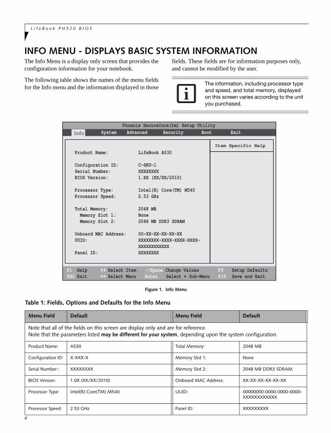
Figure 1. Info Menu
The information, including processor type and speed, and total memory, displayed on this screen varies according to the unit you purchased.
Table 1: Fields, Options and Defaults for the Info Menu
Menu Field Default Menu Field Default
Note that all of the fields on this screen are display only and are for reference.Note that the parameters listed may be different for your system, depending upon the system configuration.
Product Name: A530 Total Memory: 2048 MB
Configuration ID: X-XXX-X Memory Slot 1: None
Serial Number:: XXXXXXXX Memory Slot 2: 2048 MB DDR3 SDRAM
BIOS Version: 1.0X (XX/XX/2010) Onboard MAC Address: XX-XX-XX-XX-XX-XX
Processor Type: Intel(R) Core(TM) M540 UUID: 00000000-0000-0000-0000-XXXXXXXXXXXX
Processor Speed: 2.53 GHz Panel ID: XXXXXXXXX
Phoenix SecureCore(tm) Setup Utility
F1 HelpESC Exit
Select ItemSelect Menu
-/Space Change Values Enter Select Sub-Menu
F9 Setup DefaultsF10 Save and Exit
Info
Product Name: LifeBook A530
Configuration ID: C-SKU-1Serial Number: XXXXXXXXBIOS Version: 1.XX (XX/XX/2010)
Processor Type: Intel(R) Core(TM) M540Processor Speed: 2.53 GHz
Total Memory: 2048 MB Memory Slot 1: None Memory Slot 2: 2048 MB DDR3 SDRAM
Onboard MAC Address: 00-XX-XX-XX-XX-XXUUID: XXXXXXXX-XXXX-XXXX-XXXX- XXXXXXXXXXXXPanel ID: XXXXXXXX
System Advanced Security Boot Exit
Item Specific Help
S y s t e m M e n u
5
SYSTEM MENU – SETTING STANDARD SYSTEM PARAMETERSThe System Menu allows you to set or view the current system parameters. (See Navigating through the Setup Utility on page 2 for more information.)
The following tables show the names of the menu fields for the System menu and its submenus, all of the options for each field, the default settings and a description of
the field’s function and any special information needed to help understand the field’s use.
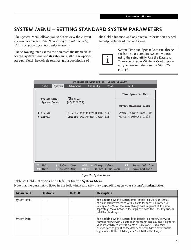
Figure 2. System Menu
System Time and System Date can also be set from your operating system without using the setup utility. Use the Date and Time icon on your Windows Control panel or type time or date from the MS-DOS prompt.
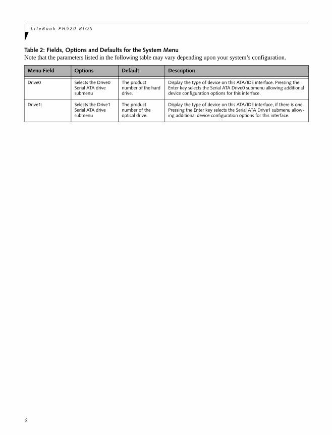
Table 2: Fields, Options and Defaults for the System MenuNote that the parameters listed in the following table may vary depending upon your system’s configuration.
Menu Field Options Default Description
System Time: –— –— Sets and displays the current time. Time is in a 24 hour formatof hours:minutes:seconds with 2 digits for each. (HH:MM:SS). Example: 16:45:57. You may change each segment of the time separately. Move between the segments with the [Tab] key and/or [Shift] + [Tab] keys.
System Date: –— –— Sets and displays the current date. Date is in a month/day/yearnumeric format with 2 digits each for month and day and 4 digits for year. (MM/DD/YYYY) for example: 03/20/2010. You maychange each segment of the date separately. Move between the segments with the [Tab] key and/or [Shift] + [Tab] keys.
Phoenix SecureCore(tm) Setup Utility
F1 HelpESC Exit
Select ItemSelect Menu
-/Space Change Values Enter Select Sub-Menu
F9 Setup DefaultsF10 Save and Exit
Info System Advanced Security Boot Exit
Item Specific Help
Adjust calendar clock.
<Tab>, <Shift-Tab>, or<Enter> selects field.
System Time: [14:57:01]System Date: [06/09/2010]
Drive0 [Hitachi HTS545032B9A300-(S1)]Drive1 [Optiarc DVD RW AD-7700S-(S2)]
L i f e B o o k P H 5 2 0 B I O S
Drive0 Selects the Drive0 Serial ATA drive submenu
The product number of the hard drive.
Display the type of device on this ATA/IDE interface. Pressing the Enter key selects the Serial ATA Drive0 submenu allowing additional device configuration options for this interface.
Drive1: Selects the Drive1 Serial ATA drive submenu
The product number of the optical drive.
Display the type of device on this ATA/IDE interface, if there is one. Pressing the Enter key selects the Serial ATA Drive1 submenu allow-ing additional device configuration options for this interface.
Table 2: Fields, Options and Defaults for the System MenuNote that the parameters listed in the following table may vary depending upon your system’s configuration.
Menu Field Options Default Description
6
S y s t e m M e n u
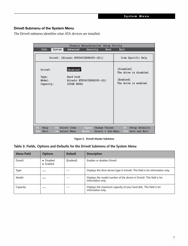
Drive0 Submenu of the System Menu
The Drive0 submenu identifies what ATA devices are installed.
Figure 3. Drive0 Master Submenu
Table 3: Fields, Options and Defaults for the Drive0 Submenu of the System Menu
Menu Field Options Default Description
Drive0: Disabled Enabled
[Enabled] Enables or disables Drive0.
Type: --- --- Displays the drive device type in Drive0. This field is for information only.
Model: --- --- Displays the model number of the device in Drive0. This field is for information only.
Capacity: --- --- Displays the maximum capacity of your hard disk. This field is for information only.
Phoenix SecureCore(tm) Setup Utility
F1 HelpESC Exit
Select ItemSelect Menu
-/SpaceEnter
F9 Setup DefaultsF10 Save and Exit
Change ValuesSelect Sub-Menu
Item Specific Help
[Disabled]The drive is disabled.
[Enabled]The drive is enabled.
Drive0: [Hitachi HTS54032B9A300-(S1)]
Drive0: [Enabled]
Type: Hard Disk Model: Hitachi HTS54032B9A300-(S1)Capacity: 320GB SATA1
Info System Advanced Security Boot Exit
7
L i f e B o o k P H 5 2 0 B I O S
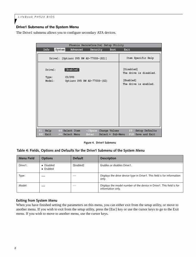
Drive1 Submenu of the System Menu
The Drive1 submenu allows you to configure secondary ATA devices.
Figure 4. Drive1 Submenu
Exiting from System MenuWhen you have finished setting the parameters on this menu, you can either exit from the setup utility, or move to another menu. If you wish to exit from the setup utility, press the [Esc] key or use the cursor keys to go to the Exit menu. If you wish to move to another menu, use the cursor keys.
Table 4: Fields, Options and Defaults for the Drive1 Submenu of the System Menu
Menu Field Options Default Description
Drive1: Disabled Enabled
[Enabled] Enables or disables Drive1.
Type: --- --- Displays the drive device type in Drive1. This field is for information only.
Model: --- --- Displays the model number of the device in Drive1. This field is for information only.
F1 HelpESC Exit
Select ItemSelect Menu
-/SpaceEnter
F9 Setup DefaultsF10 Save and Exit
Change ValuesSelect Sub-Menu
Item Specific HelpDrive1: [Optiarc DVD RW AD-7700S-(S2)]
Phoenix SecureCore(tm) Setup UtilityInfo System Advanced Security Boot Exit
Drive1: [Enabled]
Type: CD/DVDModel: Optiarc DVD RW AD-7700S-(S2)
[Disabled]The drive is disabled.
[Enabled]The drive is enabled.
8
A d v a n c e d M e n u
9
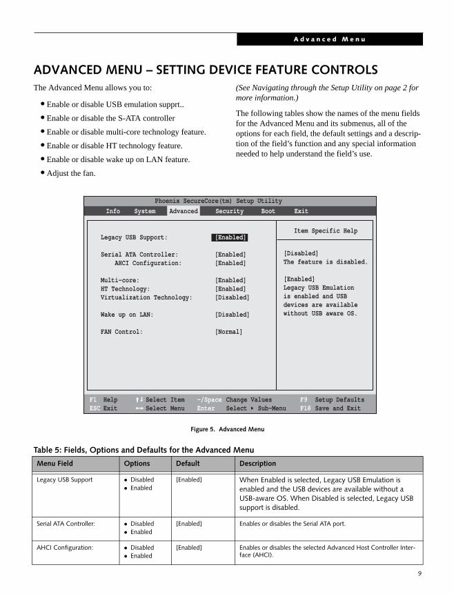
ADVANCED MENU – SETTING DEVICE FEATURE CONTROLSThe Advanced Menu allows you to:
• Enable or disable USB emulation supprt..
• Enable or disable the S-ATA controller
• Enable or disable multi-core technology feature.
• Enable or disable HT technology feature.
• Enable or disable wake up on LAN feature.
• Adjust the fan.
(See Navigating through the Setup Utility on page 2 for more information.)
The following tables show the names of the menu fields for the Advanced Menu and its submenus, all of the options for each field, the default settings and a descrip-tion of the field’s function and any special information needed to help understand the field’s use.
Figure 5. Advanced Menu
Table 5: Fields, Options and Defaults for the Advanced Menu
Menu Field Options Default Description
Legacy USB Support Disabled Enabled
[Enabled] When Enabled is selected, Legacy USB Emulation is enabled and the USB devices are available without a USB-aware OS. When Disabled is selected, Legacy USB support is disabled.
Serial ATA Controller: Disabled Enabled
[Enabled] Enables or disables the Serial ATA port.
AHCI Configuration: Disabled Enabled
[Enabled] Enables or disables the selected Advanced Host Controller Inter-face (AHCI).
F1 HelpESC Exit
Select ItemSelect Menu
-/SpaceEnter
F9 Setup DefaultsF10 Save and Exit
Change ValuesSelect Sub-Menu
Item Specific HelpLegacy USB Support: [Enabled]
Serial ATA Controller: [Enabled] AHCI Configuration: [Enabled]
Multi-core: [Enabled]HT Technology: [Enabled]Virtualization Technology: [Disabled]
Wake up on LAN: [Disabled]
FAN Control: [Normal]
[Disabled]The feature is disabled.
[Enabled]Legacy USB Emulationis enabled and USBdevices are availablewithout USB aware OS.
Info System Advanced Security Boot ExitPhoenix SecureCore(tm) Setup Utility
L i f e B o o k P H 5 2 0 B I O S
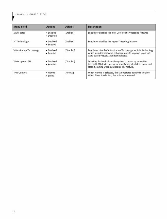
Multi-core: Enabled Disabled
[Enabled] Enables or disables the Intel Core Multi-Processing features.
HT Technology: Disabled Enabled
[Enabled] Enables or disables the Hyper-Threading features.
Virtualization Technology: Disabled Enabled
[Disabled] Enables or disables Virtualization Technology, an Intel technology which includes hardware enhancements to improve upon soft-ware-based virtualization technologies.
Wake up on LAN: Disabled Enabled
[Disabled] Selecting Enabled allows the system to wake up when the internal LAN device receives a specific signal while in power-off state. Selecting Disabled disables this feature.
FAN Control: Normal Silent
[Normal] When Normal is selected, the fan operates at normal volume. When Silent is selected, the volume is lowered.
Menu Field Options Default Description
10
S e c u r i t y M e n u
11
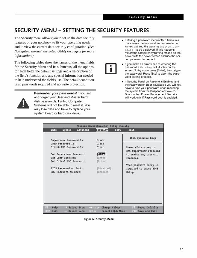
SECURITY MENU – SETTING THE SECURITY FEATURESThe Security menu allows you to set up the data security features of your notebook to fit your operating needs and to view the current data security configuration. (See Navigating through the Setup Utility on page 2 for more information.)
The following tables show the names of the menu fields for the Security Menu and its submenus, all the options for each field, the default settings and a description of the field's function and any special information needed to help understand the field's use. The default condition is no passwords required and no write protection.
Figure 6. Security Menu
Remember your passwords! If you set and forget your User and Master hard disk passwords, Fujitsu Computer Systems will not be able to reset it. You may lose data and have to replace your system board or hard disk drive.
Entering a password incorrectly 3 times in a row causes the keyboard and mouse to be locked out and the warning [System Dis-abled] to be displayed. If this happens, restart the computer by turning off and on the power with the power switch and use the cor-rect password on reboot.
If you make an error when re-entering the password a Warning will display on the screen. To try again press [Enter], then retype the password. Press [Esc] to abort the pass-word setting process.
If Security Panel on Resume is Enabled and the Password on Boot is Disabled you will not have to type your password upon resuming the system from the Suspend or Save-to-Disk modes. Power Management Security will work only if Password boot is enabled.
F1 HelpESC Exit
Select ItemSelect Menu
-/SpaceEnter
F9 Setup DefaultsF10 Save and Exit
Change ValuesSelect Sub-Menu
Item Specific Help
Press <Enter> key toset Supervisor Passwordto enable any passwordfeatures.
Then password entry isrequired to enter BIOSSetup.
Supervisor Password Is: ClearUser Password Is: ClearDrive0 HDD Password Is: Clear
Set Supervisor Password [Enter]Set User Password [Enter]Set Drive0 HDD Password: [Enter]
BIOS Password on Boot: [Disabled]HDD Password on Boot: [Enabled]
Phoenix SecureCore(tm) Setup UtilityInfo System Advanced Security Boot Exit
L i f e B o o k P H 5 2 0 B I O S
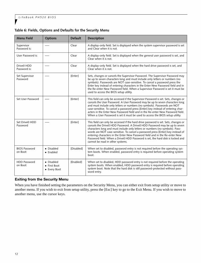
Exiting from the Security Menu
When you have finished setting the parameters on the Security Menu, you can either exit from setup utility or move to another menu. If you wish to exit from setup utility, press the [Esc] key to go to the Exit Menu. If you wish to move to another menu, use the cursor keys.
Table 6: Fields, Options and Defaults for the Security Menu
Menu Field Options Default Description
SupervisorPassword is:
–— Clear A display-only field. Set is displayed when the system supervisor password is set and Clear when it is not.
User Password is: –— Clear A display-only field. Set is displayed when the general user password is set, and Clear when it is not.
Drive0 HDD Password is:
–— Clear A display-only field. Set is displayed when the hard drive password is set, and Clear when it is not.
Set Supervisor Password
–— [Enter] Sets, changes or cancels the Supervisor Password. The Supervisor Password may be up to seven characters long and must include only letters or numbers (no symbols). Passwords are NOT case-sensitive. To cancel a password press the Enter key instead of entering characters in the Enter New Password field and in the Re-enter New Password field. When a Supervisor Password is set it must be used to access the BIOS setup utility.
Set User Password –— [Enter] This field can only be accessed if the Supervisor Password is set. Sets, changes or cancels the User Password. A User Password may be up to seven characters long and must include only letters or numbers (no symbols). Passwords are NOT case-sensitive. To cancel a password press [Enter] key instead of entering char-acters in the Enter New Password field and in the Re-enter New Password field. When a User Password is set it must be used to access the BIOS setup utility.
Set Drive0 HDD Password
–— [Enter] This field can only be accessed if the hard drive password is set. Sets, changes or cancels the Drive0 HDD Password. A Drive0 HDD Password may be up to seven characters long and must include only letters or numbers (no symbols). Pass-words are NOT case-sensitive. To cancel a password press [Enter] key instead of entering characters in the Enter New Password field and in the Re-enter New Password field. When a Drive0 HDD Password is set, the hard disk is locked and cannot be read in other systems.
BIOS Password on Boot:
Disabled Enabled
[Disabled] When set to disabled, password entry is not required before the operating sys-tem boots. When enabled, password entry is required before operating system boot.
HDD Password on Boot:
Disabled First Boot Every Boot
[Enabled] When set to disabled, HDD password entry is not required before the operating system boots. When enabled, HDD password entry is required before operating system boot. Note that the hard disk is still password-protected without pass-word entry.
12
B o o t M e n u
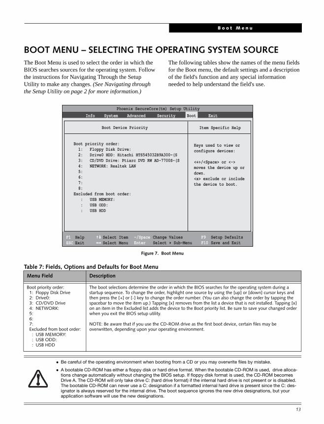
BOOT MENU – SELECTING THE OPERATING SYSTEM SOURCEThe Boot Menu is used to select the order in which the BIOS searches sources for the operating system. Follow the instructions for Navigating Through the Setup Utility to make any changes. (See Navigating through the Setup Utility on page 2 for more information.)
The following tables show the names of the menu fields for the Boot menu, the default settings and a description of the field's function and any special information needed to help understand the field's use.
Figure 7. Boot Menu
Table 7: Fields, Options and Defaults for Boot Menu
Menu Field Description
Boot priority order: 1: Floppy Disk Drive 2: Drive0: 3: CD/DVD Drive 4: NETWORK: 5: 6: 7: Excluded from boot order: : USB MEMORY: : USB ODD: : USB HDD
The boot selections determine the order in which the BIOS searches for the operating system during a startup sequence. To change the order, highlight one source by using the [up] or [down] cursor keys and then press the [+] or [-] key to change the order number. (You can also change the order by tapping the spacebar to move the item up.) Tapping [x] removes from the list a device that is not installed. Tapping [x] on an item in the Excluded list adds the device to the Boot priority list. Be sure to save your changed order when you exit the BIOS setup utility.
NOTE: Be aware that if you use the CD-ROM drive as the first boot device, certain files may be overwritten, depending upon your operating environment.
Be careful of the operating environment when booting from a CD or you may overwrite files by mistake.
A bootable CD-ROM has either a floppy disk or hard drive format. When the bootable CD-ROM is used, drive alloca-tions change automatically without changing the BIOS setup. If floppy disk format is used, the CD-ROM becomes Drive A. The CD-ROM will only take drive C: (hard drive format) if the internal hard drive is not present or is disabled. The bootable CD-ROM can never use a C: designation if a formatted internal hard drive is present since the C: des-ignator is always reserved for the internal drive. The boot sequence ignores the new drive designations, but your application software will use the new designations.
F1 HelpESC Exit
Select ItemSelect Menu
Item Specific Help
Keys used to view orconfigure devices:
<+>/<Space> or <->moves the device up ordown.<x> exclude or includethe device to boot.
Boot priority order: 1: Floppy Disk Drive: 2: Drive0 HDD: Hitachi HTS545032B9A300-(S 3: CD/DVD Drive: Ptiarc DVD RW AD-7700S-(S 4: NETWORK: Realtek LAN 5: 6: 7: 8:Excluded from boot order: : USB MEMORY: : USB ODD: : USB HDD
-/SpaceEnter
F9 Setup DefaultsF10 Save and Exit
Change ValuesSelect Sub-Menu
Boot Device Priority
Phoenix SecureCore(tm) Setup UtilityInfo System Advanced Security Boot Exit
13

L i f e B o o k P H 5 2 0 B I O S
14
Exiting from Boot MenuWhen you finish setting boot parameters with the Boot Menu, you can either exit the setup utility or move to another menu. To exit the utility, press the [Esc] key to go to the Exit Menu. To move to another menu, use the cursor keys.
E x i t M e n u
15
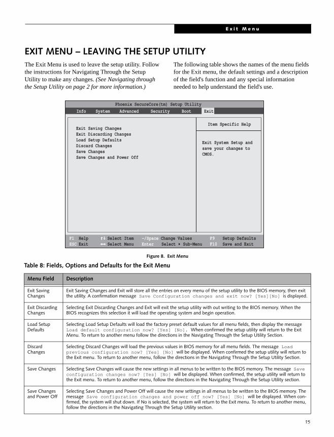
EXIT MENU – LEAVING THE SETUP UTILITYThe Exit Menu is used to leave the setup utility. Follow the instructions for Navigating Through the Setup Utility to make any changes. (See Navigating through the Setup Utility on page 2 for more information.)
The following table shows the names of the menu fields for the Exit menu, the default settings and a description of the field's function and any special information needed to help understand the field's use.
Figure 8. Exit Menu
Table 8: Fields, Options and Defaults for the Exit Menu
Menu Field Description
Exit Saving Changes
Exit Saving Changes and Exit will store all the entries on every menu of the setup utility to the BIOS memory, then exit the utility. A confirmation message Save Configuration changes and exit now? [Yes][No] is displayed.
Exit Discarding Changes
Selecting Exit Discarding Changes and Exit will exit the setup utility with out writing to the BIOS memory. When the BIOS recognizes this selection it will load the operating system and begin operation.
Load Setup Defaults
Selecting Load Setup Defaults will load the factory preset default values for all menu fields, then display the message Load default configuration now? [Yes] [No]. When confirmed the setup utility will return to the Exit Menu. To return to another menu follow the directions in the Navigating Through the Setup Utility Section.
Discard Changes
Selecting Discard Changes will load the previous values in BIOS memory for all menu fields. The message Load previous configuration now? [Yes] [No] will be displayed. When confirmed the setup utility will return to the Exit menu. To return to another menu, follow the directions in the Navigating Through the Setup Utility Section.
Save Changes Selecting Save Changes will cause the new settings in all menus to be written to the BIOS memory. The message Save configuration changes now? [Yes] [No] will be displayed. When confirmed, the setup utility will return to the Exit menu. To return to another menu, follow the directions in the Navigating Through the Setup Utility section.
Save Changes and Power Off
Selecting Save Changes and Power Off will cause the new settings in all menus to be written to the BIOS memory. The message Save configuration changes and power off now? [Yes] [No] will be displayed. When con-firmed, the system will shut down. If No is selected, the system will return to the Exit menu. To return to another menu, follow the directions in the Navigating Through the Setup Utility section.
F1 HelpESC Exit
Select ItemSelect Menu
-/Space Change Values Enter Select Sub-Menu
F9 Setup DefaultsF10 Save and Exit
Item Specific Help
Exit System Setup andsave your changes toCMOS.
Exit Saving ChangesExit Discarding ChangesLoad Setup DefaultsDiscard Changes Save ChangesSave Changes and Power Off
Info System Advanced Security Boot ExitPhoenix SecureCore(tm) Setup Utility