voltage and current measuring technologies for high
TRANSCRIPT
Received October 15, 2020, accepted November 1, 2020, date of publication November 4, 2020, date of current version November 19, 2020.
Digital Object Identifier 10.1109/ACCESS.2020.3035905
Voltage and Current Measuring Technologies for HighVoltage Direct Current Supergrids: A TechnologyReview Identifying the Options for Protection,Fault Location and Automation ApplicationsDIMITRIOS TZELEPIS 1, (Member, IEEE), VASILEIOS PSARAS 1, (Student Member, IEEE),ELENI TSOTSOPOULOU 1, (Student Member, IEEE), SOHRAB MIRSAEIDI 2, (Member, IEEE),ADAM DYŚKO1, (Member, IEEE), QITENG HONG 1,(Member, IEEE), XINZHOU DONG3, (Fellow, IEEE),STEVEN M. BLAIR 1,4, (Senior Member, IEEE), VASSILIS C. NIKOLAIDIS 5, (Senior Member, IEEE),VASSILIS PAPASPILIOTOPOULOS6, (Member, IEEE), GRZEGORZ FUSIEK 1, (Member, IEEE),GRAEME M. BURT 1, (Member, IEEE), PAWEL NIEWCZAS1,4, (Member, IEEE),AND CAMPBELL D. BOOTH1,4, (Member, IEEE)1Department of Electronics & Electrical Engineering, University of Strathclyde, Glasgow G1 1XQ, U.K.2School of Electrical Engineering, Beijing Jiaotong University, Beijing 100044, China3Department of Electrical Engineering, Tsingua University, Beijing 100084, China4Synaptec Ltd., Glasgow G1 1XW, U.K.5Department of Electrical and Computer Engineering, Democritus University of Thrace, 67100 Xanthi, Greece6PROTASIS SA, 15231 Athens, Greece
Corresponding author: Dimitrios Tzelepis ([email protected])
This work was supported in part by The Royal Society of Edinburgh (J. M. Lessells Scholarship), in part by the PHOENIX Project U.K.,under Grant SPTEN03, in part by the Innovate U.K. under Project 102594 and Project 109487-627607, in part by the U.K. Engineering andPhysical Sciences Research Council under Grant EP/P510300/1, and in part by the National Key Research and Development Plan of Chinaunder Grant 2018YFB0904602.
ABSTRACT After the occurrence of a DC-side feeder faults on HVDC transmission systems, protectionand fault detection systems are anticipated to minimize their onerous effects, by initiating fault-clearingactions such as selective tripping of circuit breakers. Following the successful fault clearance, a subsequentaction of significant importance, is the meticulous estimation of its location as a means to accelerate theline restoration, reduce down-time, limit recovery and repair costs, and hence elevate the overall availabilityand reliability of the transmission system. In order to capture DC-side fault transients for protection andfault location applications, measuring equipment is required to be placed on HVDC installations. This paperfocuses primarily on reviewing the available technologies from the perspective of enabling protection, faultlocation and automation applications in HVDC systems. The review constitutes a mapping of protectionand fault location functions, against the available voltage and current measuring technologies, ultimatelyunlocking insights for selecting measuring equipment based on the desirable characteristics of protection andfault location systems. The review also revealed that the frequency characteristics of each sensing scheme,primarily refers to the bandwidth of the primary sensor, whereas the overall bandwidth of the completemeasuring scheme may be further restricted by the secondary converter and corresponding data acquisitionsystem and signal processing electronics. It was also identified that the use of RC voltage dividers hasprevailed for voltage measurements for HVDC applications, due to their superior advantages. The choiceof a suitable device for current measurement, depends mainly on the fault detection method used and thefrequency range it operates. In particular, the review revealed that fault detection and protection methodsare mainly concentrated in a frequency spectrum ranging from a few kHz to 100 kHz, while fault locationmethods require measurements with a frequency range from 100 kHz up to 2 MHz.
INDEX TERMS HVDC technology, fault detection, fault location, power system measurements.
The associate editor coordinating the review of this manuscript and
approving it for publication was Dazhong Ma .
203398 This work is licensed under a Creative Commons Attribution 4.0 License. For more information, see https://creativecommons.org/licenses/by/4.0/ VOLUME 8, 2020

D. Tzelepis et al.: Voltage and Current Measuring Technologies for High Voltage Direct Current Supergrids
NOMENCLATURE1D− CNN One-Dimensional Convolutional Neural
Network1i Differential Current1v Differential Voltage∫VLdc Integral of DC reactor voltage∇v voltage gradientρ(d, x) Pearson’s correlation coefficientATTW Arrival Time of Traveling WavesBGO Bismuth Germanium OxideCLRP Current Limiting Reactor PowerConvoP Convolution of PowerCovoI Covariance of CurrentCPTE Convolution Power-based Transient
EnergyCRP Current Reduction PhenomenonCS Cosine DistanceCSoTW Cosine Similarity of Travelling WavesCWT Continuous Wavelet Transformd(i/v)/dt Rate of change of current-voltage ratiodI Deviation of current from its moving
averagedi/dt Rate of change of currentDiroI Direction of CurrentDNF Dominant Natural Frequencydv/dt Rate of change of voltageDVTW Differential Voltage Travelling WaveDWT Discrete Wavelet TransformDWT (i) Discrete Wavelet Transform of CurrentDWT (v) Discrete Wavelet Transform of VoltageEEMD Ensemble Empirical Mode DecompositionEMD Empirical Mode DecompositionEML Extreme Machine LearningEMTR Electro-Magnetic Time Reversalfit(i) Time-domain fitting of fault currentFLC Fault Location CoefficientFPT First Peak TimeFSC Frequency Spectrum CorrelationGFS Generic Fuzzy SystemGTBL Graph Theory-Based LemmasHFTVE High Frequency Transient-Voltage EnergyHHT Hilbert–Huang TransformHVDC High Voltage Direct CurrentIED Intelligent Electronic DeviceLCC Line Commutated ConvertersLPCT Low Power Current TransformersLPIT Low Power Instrument TransformersLPVT Low Power Voltage TransformersMAD Median Absolute ValueMMC Modular Multi-level ConvertersModVel Modal VelocitiesMTDC Mutli Terminal Direct CurrentMVVDF Minimum Value of Voltage Distribution
Functions
NBC Nave Bayer ClassifierOC Over-CurrentOHL Over-Head LinesOV Over-VoltagePCA Principal Component AnalysisPCC Pearson’s Correlation CoefficientsPTG Pole-To-GroundPTP Pole-To-PoleQCD Quickest Change DetectionRES Renewable Energy SourcesROHTLFC Ratio Of High-To-Low-Frequency Cur-
rentsROTV Ratio of Transient VoltagesRT − BWT Real-Time Boundary Wavelet TransformSATD Surge Arrival Time Differencesgn(di/dt) Sign/polarity of current derivativesgn(dv/dt) Sign/polarity of voltage derivativesgn(i) Sign/polarity of currentsgn(WTMM ) Sign/polarity of Wavelet Transform Modu-
lus MaximaSMVS Simularity Measure of Voltage SignalsSVM Support Vector MachinesSWT Stationary Wavelet TransformTER Ratio of Transient EnergyTHFE Transient High-Frequency EnergyTVAC Transient Average Value of CurrentTVE Transient Voltage EnergyTWFSR Travelling Wave Frequency Spectrum
AnalysisTWD Travelling Wave DifferentialUV Under-VoltageVCI Voltage Change IntegralVPI Voltage Pulse InjectionWAF Weughted Averaging FunctionsWCoV Wavelet Coefficients of VoltageWE(i) Wavelet Energy of CurrentWER(i) Wavelet Energy Ratios of CurrentWPEE Wavelet-Packet Energy EntropyWT Wavelet TransformWTMM Wavel Transform Modulus MaximaWTMM (i) Wavelet Transform Modulus Maxima cur-
rent
I. INTRODUCTIONDue to the high penetration of Renewable Energy Sources(RES), demand and supply equilibrium is anticipated to beone of the key challenges in future operation of power sys-tems. Consequently, there is an emerging need for meshedinterlinks between different countries as a means to effi-ciently exchange the available energy and therefore increasethe flexibility and security of supply.
The concept of supergrid has been identified as a possiblemechanism towards a new backbone transmission system,allowing massive integration of RES [1]–[5]. High VoltageDirect Current (HVDC) links, utilizing Voltage Source Con-
VOLUME 8, 2020 203399
D. Tzelepis et al.: Voltage and Current Measuring Technologies for High Voltage Direct Current Supergrids
verters (VSCs), are expected to become the favourable tech-nology for realization of such a supergrid [6]. This is drivenby the fact that such systems are characterized by superiorfeatures in terms of operational losses, system stability andcost.
An extension of existing HVDC links (e.g. point-to-point)is a Multi-Terminal Direct-Current (MTDC) which deploysmore than two HVDC station terminals, ultimately creatinga DC grid. An MTDC grid can further advance the techno-economical offerings of HVDC technology and thereforeaccelerate the supergrid realization. However, the are stilltechnical outstanding challenges to be resolved and hence itis not a trivial task to design and operate an MTDC super-grid. Consequently, it is of utmost importance to investigate,analyze and mitigate the emerging challenges introducedby MTDC systems in order to promote their widespreaddeployment.
To enable more efficient interchange of power and also toharness RES, there is a business case for setting up a Euro-pean Supergrid. A supergrid can be defined as a transmissionbackbone which allows massive integration of RES [6]–[8].It has the ability to connect different remote energy sources toan existing grid, offer improved controllability, bring efficientenergy balance over a wide geographic spread, and mostsignificantly, allow amore diversified energy portfolio. Thereare several concepts for the topological setup of such a super-grid, proposed by several organizations which are depictedin Figure 1.
FIGURE 1. European Supergrid concepts: a) Wind Energy Europe [4], b)Friends of Supergrid [3], c) Airtricity [2], d) European Commission [5].
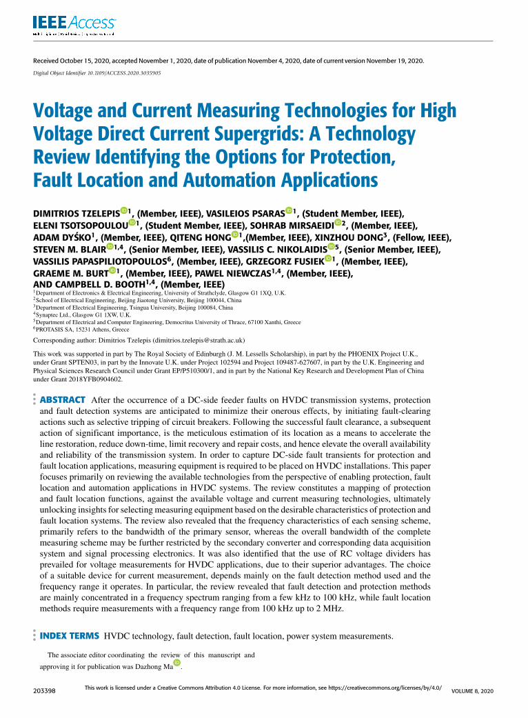
Besides the European Supergrid, there are proposed con-cepts for setting up supergrids in Asia and United States ofAmerica [1], which are shown in Figure 2a and Figure 2brespectively.
It is therefore evident that in many respects, the develop-ment of a wide HVDC-based supergrid is a well-crafted strat-egy, especially in Europe due to its leading role in RES. Eventhough HVDC technology introduces many major advan-tages (refer to Table 1) which future supergrids are basedupon, it is also accompanied by several technical barriers andchallenges.
FIGURE 2. Non-European Supergrid concepts: a) North-East Asia [9],United States of America [8], [10].
TABLE 1. VSC HVDC trade-offs.
Despite the fact that there several issues to be resolved forthe widespread deployment ofMTDC grids, there are specificchallenges associated with DC-side fault management, whichis a very critical issue when considering HVDC technology.In order to capture DC-side fault transients for protection,control and fault location applications, measuring equipmentis required to be placed on HVDC installations. This papermainly focuses on reviewing the available technologies fromthe perspective of enabling protection, fault location andautomation applications in HVDC systems. Even thoughsome relevant review on protection and fault location func-tions has been conducted in [11]–[13], the work did notprovide any profound insight with respect to the element ofmeasuring technologies towards achieving the desired char-acteristics of those functions.
Section II includes a review of protection and fault locationfunctions, which are sorted according to voltage and cur-rent measurements, communication and sampling frequencyrequirements. Sections III and IV provide a detailed analysisand discussion of the voltage and current sensing equip-ment for HVDC installations. Section V presents a mappingexercise of protection and fault location functions againstthe available voltage and current measuring technologiesand essentially unlocks the insights for selecting measuringequipment. In Section VI this paper also analyzes and dis-cusses the available options for automation applications, stan-dards and protocols for HVDC installations in conjunctionwith the realization of the desirablemeasuring characteristics.Finally, conclusions are drawn in Section VII.
II. PROTECTION AND FAULT LOCATION IN HVDC GRIDSFor the practical operation and employment of MTDC grids,there are numerous technical outstanding issues to be solved.Major categories of these include power exchange con-trol [14]–[16], dynamic behavior and stability [17]–[19], sys-tems and grid integration [20]–[22] and finally, fault manage-
203400 VOLUME 8, 2020
D. Tzelepis et al.: Voltage and Current Measuring Technologies for High Voltage Direct Current Supergrids
ment accounting for detection, protection and fault location[23]–[25]. Consequently, it is of utmost importance toinvestigate, analyze and mitigate the emerging challengesintroduced by MTDC systems in order to promote theirwidespread deployment.
DC-side faults occurring in HVDC systems are generallycharacterized by large inrush currents (escalating over a veryshort period of time), initiated by the discharge of storedenergy in the relevant capacitances of the entire system. Suchcapacitances can be found on the DC side of converters, trans-mission line capacitances, and also within modular multi-level converters (i.e. sub-module capacitors).
When DC-side faults occur in MTDC grids, the associ-ated DC protection systems are anticipated to minimize theonerous effects by disconnecting the faulted sections whileallowing the remaining healthy part of the grid to maintainits operational status. Such requirements imply the need fortransient characterization of DC-side faults, ultimately lead-ing to the development of reliable, fast, and sensitive DCprotection methods. Therefore, one of the main objectivesof protection area is to demonstrate solutions to mitigate thekey challenges associated with the protection ofMTDC grids,ultimately reducing the risk for the realization of HVDC-based supergrids.
Specifically, regarding fault-management issues in HVDCgrids, according to ‘ENTSO-E Code on HVDC Connec-tions and DC-connected Park Modules’ [26], HVDC sys-tems (including overhead lines), shall have the capability torecover from DC-side transient faults. In addition to this,it is highlighted that with regard to priority ranking in thearea of control and protection, the owner/operator of HVDCshall organize its control and protection equipment in orderto comply with the following priorities, listed in decreasingorder of importance:
• Protection (for HVDC and network systems)• Control of active power (for emergency assistance)• Synthetic inertia (if applicable)• Automatic restoration actions• Limited Frequency Sensitive Mode (LFSM)• Frequency control and Frequency Sensitive Mode(FSM)
• Constraint of power gradient
It is therefore evident that protection is of the highestimportance for the healthy operation of HVDC grids.
Additionally, as reported in ‘IEEE Guide for EstablishingBasic Requirements for High-Voltage Direct-Current Trans-mission Protection and Control Equipment’ [27], along withthe HVDC protection equipment, the following importantsubsystems should interact closely and effectively to imple-ment the required functions:
• DC line fault locator• Electrode line monitoring equipment• Transient fault recorder• Station clock synchronization equipment• Harmonics monitoring equipment
• Converter valve cooling control and protectionequipment
• DC measuring equipmentTherefore, fault location is another important function
required to run alongside protection. This is due to thefact that after the successful detection and isolation of afault, and assuming the fault is permanent, the meticulousestimation of its location is of significant importance asa means to accelerate the line restoration, reduce down-time of the system, limit recovery and repair costs, andhence elevate the overall availability and reliability of thetransmission system. This is particularly important in thecase of a supergrid, where a single unit disconnectioncan tremendously affect power exchange between differentcountries.
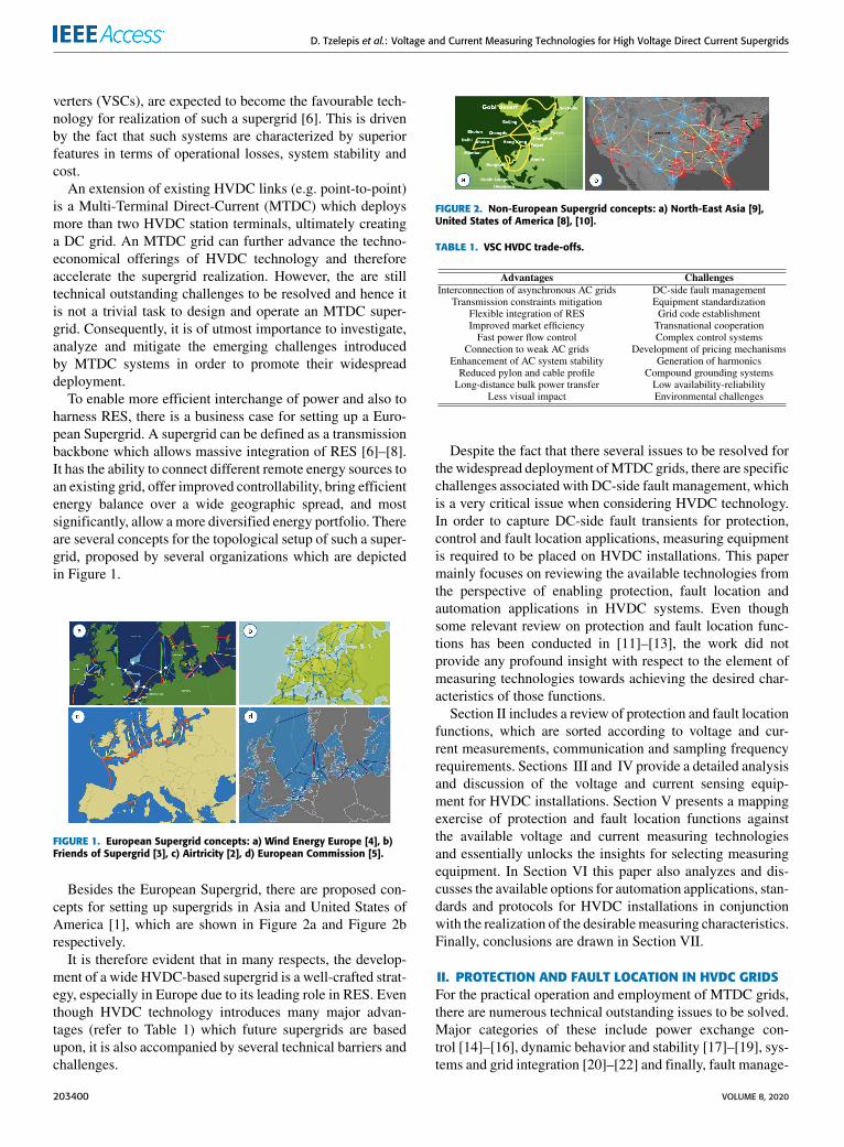
In Table 2 and 3, the design elements for a variety of DCprotection and fault location solutions found in the technicalliterature have been summarized, showcasing among othersthe necessary sampling frequencies in each case. The requiredsampling frequency is practically enabled by appropriatemeasuring and sensing equipment. A detailed analysis of pro-tection and fault location can be found in Appendix A and Brespectively.
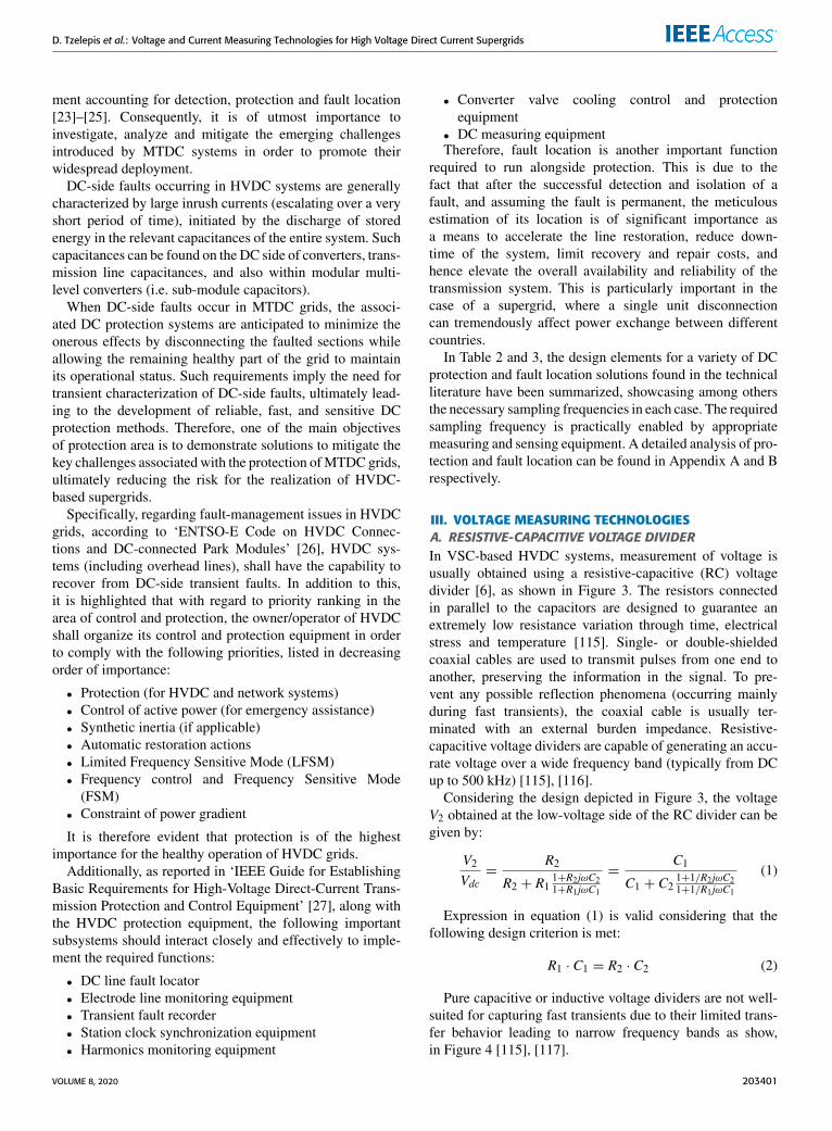
III. VOLTAGE MEASURING TECHNOLOGIESA. RESISTIVE-CAPACITIVE VOLTAGE DIVIDERIn VSC-based HVDC systems, measurement of voltage isusually obtained using a resistive-capacitive (RC) voltagedivider [6], as shown in Figure 3. The resistors connectedin parallel to the capacitors are designed to guarantee anextremely low resistance variation through time, electricalstress and temperature [115]. Single- or double-shieldedcoaxial cables are used to transmit pulses from one end toanother, preserving the information in the signal. To pre-vent any possible reflection phenomena (occurring mainlyduring fast transients), the coaxial cable is usually ter-minated with an external burden impedance. Resistive-capacitive voltage dividers are capable of generating an accu-rate voltage over a wide frequency band (typically from DCup to 500 kHz) [115], [116].
Considering the design depicted in Figure 3, the voltageV2 obtained at the low-voltage side of the RC divider can begiven by:
V2Vdc=
R2
R2 + R11+R2jωC21+R1jωC1
=C1
C1 + C21+1/R2jωC21+1/R1jωC1
(1)
Expression in equation (1) is valid considering that thefollowing design criterion is met:
R1 · C1 = R2 · C2 (2)
Pure capacitive or inductive voltage dividers are not well-suited for capturing fast transients due to their limited trans-fer behavior leading to narrow frequency bands as show,in Figure 4 [115], [117].
VOLUME 8, 2020 203401

D. Tzelepis et al.: Voltage and Current Measuring Technologies for High Voltage Direct Current Supergrids
TABLE 2. Taxonomy of HVDC protection systems according to voltage, current, communication and sampling frequency requirements.
The features of RC dividers which make them a verycompelling option for measurement of voltage are listedbelow [115], [116]:
• No saturable cores leading to ferroresonance-free char-acteristics
• Superior transient characteristics• Compliance with secondary technology base on micro-processors
• Design enabling short-circuit proof characteristics• No need for disconnection for commissioning purposes(e.g. cable test)
• Significant width and weight minimization
B. OPTICAL SENSORS BASED ON POCKELS EFFECTAn optical electric sensing technology utilizing the Pockelseffect is presented in [118]–[122]. Such optical voltage sen-
203402 VOLUME 8, 2020
D. Tzelepis et al.: Voltage and Current Measuring Technologies for High Voltage Direct Current Supergrids
TABLE 3. Taxonomy of HVDC fault location systems according to voltage,current and sampling frequency requirements.
FIGURE 3. Resistive-capacitive voltage divider.
FIGURE 4. Comparison of bandwidth of an inductive VT, a capacitiveVT and an RC divider [115].
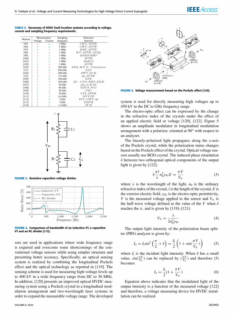
sors are used in applications where wide frequency rangeis required and overcome some shortcomings of the con-ventional voltage sensors while using simpler structure andpresenting better accuracy. Specifically, an optical sensingsystem is realized by combining the longitudinal Pockelseffect and the optical technology as reported in [119]. Thesensing scheme is used for measuring high-voltage levels upto 400 kV in a wide frequency range from DC to 30 MHz.In addition, [120] presents an improved optical HVDC mea-suring system using a Pockels crystal in a longitudinal mod-ulation arrangement and two-wavelength laser systems inorder to expand the measurable voltage range. The developed
FIGURE 5. Voltage measurement based on the Pockels effect [120].
system is used for directly measuring high voltages up to450 kV in the DC to GHz frequency range.
The electro-optic effect can be expressed by the changein the refractive index of the crystals under the effect ofan applied electric field or voltage [120], [122]. Figure 5shows an amplitude modulator in longitudinal modulationarrangement with a polarizer, oriented at 90o with respect toan analyzer.
The linearly-polarized light propagates along the z-axisof the Pockels crystal, while the polarization status changesbased on the Pockels effect of the crystal. Optical voltage sen-sors usually use BGO crystal. The induced phase retardationδ between two orthogonal optical components of the outputlight is given by [122]:
δπ lλn30γ41E =
πVVπ
(3)
where λ is the wavelength of the light, n0 is the ordinaryrefractive index of the crystal, l is the length of the crystal,E isthe exterior electric field, γ41 is the electro-optic permittivity,V is the measured voltage applied to the sensor and Vπ isthe half-wave voltage defined as the value of the V when δreaches the π , and is given by [119]–[121]:
Vπ =λ
2n30γ41(4)
The output light intensity of the polarization beam split-ter (PBS) analyzer is given by:
Io = Iisin2(π2+ δ
)=Ii2
(1+ sin(
πVVπ
))
(5)
where Ii is the incident light intensity. When δ has a smallvalue, sin(πVVπ ) can be replaced by (πVVπ ) and therefore (5)becomes
Io =Ii2(1+
πVVπ
) (6)
Equation above indicates that the modulated light of theoutput intensity is a function of the measured voltage [122]and therefore, a voltage measuring device for HVDC instal-lation can be realized.
VOLUME 8, 2020 203403
D. Tzelepis et al.: Voltage and Current Measuring Technologies for High Voltage Direct Current Supergrids
FIGURE 6. Classification of DC current measuring technologies.
However, the use of the aforementioned sensing tech-nology for DC voltage measurements includes some uncer-tainties which are affected by several factors like the lightsource, the current-to-voltage converter and the unwantedcross electric field [119]. Furthermore, some technical chal-lenges which have to be addressed include:• The moving electric charges in the crystal causes drift ofthe output intensity of the light sources
• The modulated signal of the DC voltage is difficult to bedistinguished from the light intensity
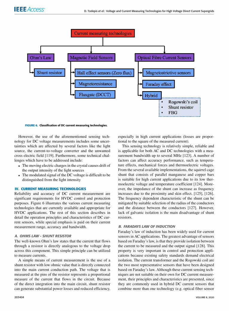
IV. CURRENT MEASURING TECHNOLOGIESReliability and accuracy of DC current measurement aresignificant requirements for HVDC control and protectionpurposes. Figure 6 illustrates the various current measuringtechnologies that are currently available and appropriate forHVDC applications. The rest of this section describes indetail the operation principles and characteristics of DC cur-rent sensors, while special emphasis is paid on their currentmeasurement range, accuracy and bandwidth.
A. OHMS LAW - SHUNT RESISTORThe well-known Ohm’s law states that the current that flowsthrough a resistor is directly analogous to the voltage dropacross this component. This simple principle can be utilizedto measure currents.
A simple means of current measurement is the use of ashunt resistor with low ohmic value that is directly connectedinto the main current conduction path. The voltage that ismeasured at the pins of the resistor represents a proportionalmeasure of the current that flows in the circuit. Becauseof the direct integration into the main circuit, shunt resistorcan generate substantial power losses and reduced efficiency,
especially in high current applications (losses are propor-tional to the square of the measured current).
This sensing technology is relatively simple, reliable andis applicable for both AC and DC technologies with a mea-surement bandwidth up to several MHz [123]. A number offactors can affect accuracy performance, such as tempera-ture effects, mechanical forces and thermoelectric voltages.From the several available implementations, the squirrel cageshunt that consists of parallel manganese and copper barsis suitable for high current applications due to its low ther-moelectric voltage and temperature coefficient [124]. More-over, the impedance of the shunt can increase as frequencyincreases due to the proximity and skin effect. [125], [126].The frequency dependent characteristic of the shunt can bemitigated by suitable selection of the radius of the conductorsand the distance between the conductors [127]. However,lack of galvanic isolation is the main disadvantage of shuntresistors.
B. FARADAYS LAW OF INDUCTIONFaraday’s law of induction has been widely used for currentsensors in AC applications. The greatest advantage of sensorsbased on Faraday’s law, is that they provide isolation betweenthe current to be measured and the output signal [128]. Thisproperty is very important in control and protection appli-cations because existing safety standards demand electricalisolation. The current transformer and the Rogowski coil arethe two most representative sensors that have been designedbased on Faraday’s law. Although these current sensing tech-niques are not suitable on their own for DC current measure-ment, their principles and characteristics are presented, sincethey are commonly used in hybrid DC current sensors thatcombine more than one technology (e.g. optical fiber sensor
203404 VOLUME 8, 2020
D. Tzelepis et al.: Voltage and Current Measuring Technologies for High Voltage Direct Current Supergrids
with a Rogowski coil), or in devices with extra componentsthat permit DC current measurements
The working principle of both sensors is explained throughthe Ampere’s law that relates the magnetic flux densityaround a loop to the enclosed current that passes through theloop, as shown in equation (7)∮
C
EB · Edl = µ0µr ic (7)
When the primary current ic flows in the center of the loop,the flux density B is given by
EB =µ0µr ic2πr
(8)
This relationship is used in conjunction with Faraday’slaw of induction for both sensors of this family to calculatethe induced voltage in the measurement winding, which isproportional to the main current.
1) CURRENT TRANSFORMERA typical construction of current transformer (CT) consistsof a core material with high relative permeability and twowindings. The main current flow path serves as the onlyprimary turn, while several secondary turns are employed toprovide a representative measurement of the main current.Similar to a conventional transformer, the primary current istranslated to a secondary current with a magnitude that isdictated by the turns ratio of the windings. Thus, the sec-ondary winding together with the core form the measuringhead of the CT.A carefully designed resistor (Rs) is connectedin the secondary winding. The magnetic flux generated bythe secondary current that flows through Rs counters the fluxgenerated by the main current. The purpose of this resistor isto convert the generated compensated current into a voltagesignal. The induced voltage can be derived as follows
u = −Ndφdt= −NA
dBdt= −
NAµ0µr
2πr(ic − Nis)
ddt
(9)
where ic is the primary current, is the secondary current andµr the relative magnetic permeability of the core material.Solving this equation for is yields the following equation
is =icN−
lmN 2Aµ0µr
∫tusdt (10)
The above equation implies that the current transformer isunable to measure DC currents and consequently, additionalmodifications are required to perform this task.
2) ROGOWSKISimilar to the current transformer, the Rogowski coil orair-core coil current sensor exploits Faraday’s law in orderto measure currents. The main differences compared withthe basic construction of a current transformer is that theRogowski coil uses a non-magnetic core material and it doesnot include the burden resistor in the secondary winding.The measuring head consists of a coil that is wound uni-formly around a non-magnetic former, which in turn forms a
FIGURE 7. Typical illustration of bandwidth for closed-loop and CT mode.
closed loop around the main current carrying conductor. Theconductor’s position needs to be in the center of the coil tomitigate measurement errors [128].
According to Faraday’s law, a voltage is induced in theRogowski coil that is proportional to the rate of change ofcurrent as shown by:
u = −Ndφdt= −
NAµ0
2πrdicdt
(11)
where N is the number of turns and A is the cross-sectionalarea of the former. This equation shows that the voltageis proportional to the derivative of the main current ic thatneeds to be measured. Hence, an integrator is employed toproduce a signal that is directly proportional to the maincurrent. Since the main principle of this sensor relies on thedetection of a change in flux (i.e., current change), Rogowskicoil cannot be directly used to measure DC currents. Owingto the absence of a magnetic core, the Rogowski coil demon-strates very good linearity and is capable of carrying verylarge currents (tens of kAs) over an extended bandwidthup to several tens of MHz [129]. Recently, current sen-sors have been designed based on the Rogowski coil prin-ciple that can be fabricated using a printed-circuit board(PCB), appropriate for installation in individual modules ofpower converters, demonstrating high accuracy and extendedbandwidth [130], [131].
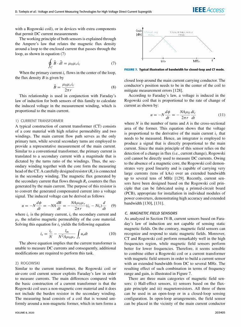
C. MAGNETIC FIELD SENSORSAs analyzed in Section IV-B, current sensors based on Fara-day’s law of induction are not capable of sensing staticmagnetic fields. On the contrary, magnetic field sensors canrecognize and respond to static magnetic fields. Moreover,CT and Rogowski coil perform remarkably well in the highfrequencies region, while magnetic field sensors performbetter for lower frequencies. Therefore, it seems sensibleto combine either a Rogowski coil or a current transformerwith magnetic field sensors in order to build a current sensorwith an extended bandwidth from DC to several MHz. Theresulting effect of such combination in terms of frequencyrange and gain, is illustrated in Figure 7.
There are three main categories of magnetic field sen-sors: i) Hall-effect sensors, ii) sensors based on the flux-gate principle and iii) magnetoresistors. All three of themcan be used in an open-loop or in a closed-loop sensingconfiguration. In open-loop arrangements, the field sensorcan be placed in the vicinity of the main current conductor
VOLUME 8, 2020 203405
D. Tzelepis et al.: Voltage and Current Measuring Technologies for High Voltage Direct Current Supergrids
FIGURE 8. Illustration of Hall effect through a conductive material.
or alternatively, a magnetic core is used to concentrate themagnetic field that is generated from the enclosed conductoronto the magnetic field sensor that is situated in the airgapof the core material. The former is susceptible to the skineffect and external magnetic fields, while in the latter con-figuration the sensitivity is substantially improved due to thehigh magnetic permeability of the core material, and the skineffect is eliminated. Nevertheless, excessive currents can leadto the saturation of the core, in which case degaussing isrequired. Additional limiting factors for both topologies arethe relatively low bandwidth and the significant thermal driftof the sensing element [128]. Nevertheless, the open-loopconfiguration constitutes a simple and cost-effective solution.
In the closed-loop configuration, the magnetic field sen-sor’s output voltage is used as a feedback control signal todrive a compensating current in a secondary winding. Thisis wound in the magnetic core to counter the magnetic fluxthat is generated by the primary current. This configurationresults in a zero-flux transducer. With the use of a secondarywinding, the transducer operates as a current transformerin the high frequency region, resulting in extended band-width [132]. The closed-loop sensing configuration reducessignificantly or eliminates the thermal drift and dramaticallyimproves the performance of the sensor [133]. Complexityand extra cost are the limitations of this technology.
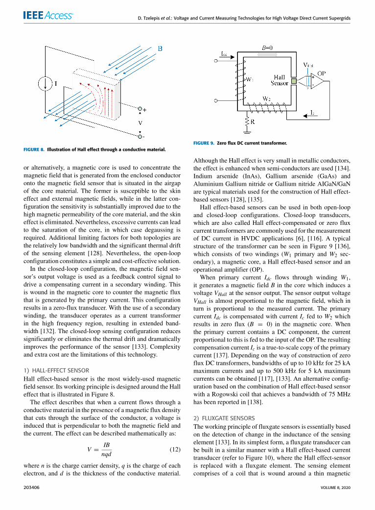
1) HALL-EFFECT SENSORHall effect-based sensor is the most widely-used magneticfield sensor. Its working principle is designed around the Halleffect that is illustrated in Figure 8.
The effect describes that when a current flows through aconductive material in the presence of a magnetic flux densitythat cuts through the surface of the conductor, a voltage isinduced that is perpendicular to both the magnetic field andthe current. The effect can be described mathematically as:
V =IBnqd
(12)
where n is the charge carrier density, q is the charge of eachelectron, and d is the thickness of the conductive material.
FIGURE 9. Zero flux DC current transformer.
Although the Hall effect is very small in metallic conductors,the effect is enhanced when semi-conductors are used [134].Indium arsenide (InAs), Gallium arsenide (GaAs) andAluminium Gallium nitride or Gallium nitride AIGaN/GaNare typical materials used for the construction of Hall effect-based sensors [128], [135].
Hall effect-based sensors can be used in both open-loopand closed-loop configurations. Closed-loop transducers,which are also called Hall effect-compensated or zero fluxcurrent transformers are commonly used for the measurementof DC current in HVDC applications [6], [116]. A typicalstructure of the transformer can be seen in Figure 9 [136],which consists of two windings (W1 primary and W2 sec-ondary), a magnetic core, a Hall effect-based sensor and anoperational amplifier (OP).
When primary current Idc flows through winding W1,it generates a magnetic field B in the core which induces avoltage VHall at the sensor output. The sensor output voltageVHall is almost proportional to the magnetic field, which inturn is proportional to the measured current. The primarycurrent Idc is compensated with current Ic fed to W2 whichresults in zero flux (B = 0) in the magnetic core. Whenthe primary current contains a DC component, the currentproportional to this is fed to the input of the OP. The resultingcompensation current Ic is a true-to-scale copy of the primarycurrent [137]. Depending on the way of construction of zeroflux DC transformers, bandwidths of up to 10 kHz for 25 kAmaximum currents and up to 500 kHz for 5 kA maximumcurrents can be obtained [117], [133]. An alternative config-uration based on the combination of Hall effect-based sensorwith a Rogowski coil that achieves a bandwidth of 75 MHzhas been reported in [138].
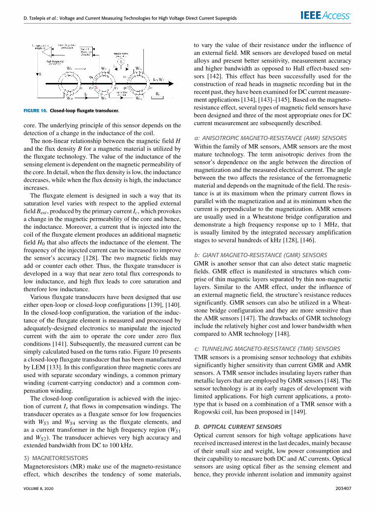
2) FLUXGATE SENSORSThe working principle of fluxgate sensors is essentially basedon the detection of change in the inductance of the sensingelement [133]. In its simplest form, a fluxgate transducer canbe built in a similar manner with a Hall effect-based currenttransducer (refer to Figure 10), where the Hall effect-sensoris replaced with a fluxgate element. The sensing elementcomprises of a coil that is wound around a thin magnetic
203406 VOLUME 8, 2020
D. Tzelepis et al.: Voltage and Current Measuring Technologies for High Voltage Direct Current Supergrids
FIGURE 10. Closed-loop fluxgate transducer.
core. The underlying principle of this sensor depends on thedetection of a change in the inductance of the coil.
The non-linear relationship between the magnetic field Hand the flux density B for a magnetic material is utilized bythe fluxgate technology. The value of the inductance of thesensing element is dependent on the magnetic permeability ofthe core. In detail, when the flux density is low, the inductancedecreases, while when the flux density is high, the inductanceincreases.
The fluxgate element is designed in such a way that itssaturation level varies with respect to the applied externalfieldBext , produced by the primary current Ic, which provokesa change in the magnetic permeability of the core and hence,the inductance. Moreover, a current that is injected into thecoil of the fluxgate element produces an additional magneticfield H0 that also affects the inductance of the element. Thefrequency of the injected current can be increased to improvethe sensor’s accuracy [128]. The two magnetic fields mayadd or counter each other. Thus, the fluxgate transducer isdeveloped in a way that near zero total flux corresponds tolow inductance, and high flux leads to core saturation andtherefore low inductance.
Various fluxgate transducers have been designed that useeither open-loop or closed-loop configurations [139], [140].In the closed-loop configuration, the variation of the induc-tance of the fluxgate element is measured and processed byadequately-designed electronics to manipulate the injectedcurrent with the aim to operate the core under zero fluxconditions [141]. Subsequently, the measured current can besimply calculated based on the turns ratio. Figure 10 presentsa closed-loop fluxgate transducer that has been manufacturedby LEM [133]. In this configuration three magnetic cores areused with separate secondary windings, a common primarywinding (current-carrying conductor) and a common com-pensation winding.
The closed-loop configuration is achieved with the injec-tion of current Is that flows in compensation windings. Thetransducer operates as a fluxgate sensor for low frequencieswith WS3 and WS4 serving as the fluxgate elements, andas a current transformer in the high frequency region (WS1and WS2). The transducer achieves very high accuracy andextended bandwidth from DC to 100 kHz.
3) MAGNETORESISTORSMagnetoresistors (MR) make use of the magneto-resistanceeffect, which describes the tendency of some materials,
to vary the value of their resistance under the influence ofan external field. MR sensors are developed based on metalalloys and present better sensitivity, measurement accuracyand higher bandwidth as opposed to Hall effect-based sen-sors [142]. This effect has been successfully used for theconstruction of read heads in magnetic recording but in therecent past, they have been examined for DC currentmeasure-ment applications [134], [143]–[145]. Based on the magneto-resistance effect, several types of magnetic field sensors havebeen designed and three of the most appropriate ones for DCcurrent measurement are subsequently described.
a: ANISOTROPIC MAGNETO-RESISTANCE (AMR) SENSORSWithin the family of MR sensors, AMR sensors are the mostmature technology. The term anisotropic derives from thesensor’s dependence on the angle between the direction ofmagnetization and the measured electrical current. The anglebetween the two affects the resistance of the ferromagneticmaterial and depends on the magnitude of the field. The resis-tance is at its maximum when the primary current flows inparallel with the magnetization and at its minimum when thecurrent is perpendicular to the magnetization. AMR sensorsare usually used in a Wheatstone bridge configuration anddemonstrate a high frequency response up to 1 MHz, thatis usually limited by the integrated necessary amplificationstages to several hundreds of kHz [128], [146].
b: GIANT MAGNETO-RESISTANCE (GMR) SENSORSGMR is another sensor that can also detect static magneticfields. GMR effect is manifested in structures which com-prise of thin magnetic layers separated by thin non-magneticlayers. Similar to the AMR effect, under the influence ofan external magnetic field, the structure’s resistance reducessignificantly. GMR sensors can also be utilized in a Wheat-stone bridge configuration and they are more sensitive thanthe AMR sensors [147]. The drawbacks of GMR technologyinclude the relatively higher cost and lower bandwidth whencompared to AMR technology [148].
c: TUNNELING MAGNETO-RESISTANCE (TMR) SENSORSTMR sensors is a promising sensor technology that exhibitssignificantly higher sensitivity than current GMR and AMRsensors. A TMR sensor includes insulating layers rather thanmetallic layers that are employed by GMR sensors [148]. Thesensor technology is at its early stages of development withlimited applications. For high current applications, a proto-type that is based on a combination of a TMR sensor with aRogowski coil, has been proposed in [149].
D. OPTICAL CURRENT SENSORSOptical current sensors for high voltage applications havereceived increased interest in the last decades, mainly becauseof their small size and weight, low power consumption andtheir capability to measure both DC and AC currents. Opticalsensors are using optical fiber as the sensing element andhence, they provide inherent isolation and immunity against
VOLUME 8, 2020 203407

D. Tzelepis et al.: Voltage and Current Measuring Technologies for High Voltage Direct Current Supergrids
FIGURE 11. Optical fiber current sensor as per the Faraday effect.
electromagnetic interference, features that are of vital impor-tance in high voltage applications. [150]. Current sensorsbased on optical sensing commonly rely on the Faraday effect(or magneto-optic effect).
1) OPTICAL SENSORS BASED ON FARADAY EFFECTAccording to the Faraday effect, when left- and right-handcircularly polarized light waves pass through a transparentmaterial under the effect of a magnetic field that is orientedin the same direction as the traversing light, the relative speedof the left- and right-hand circularly polarized light speedchanges slightly causing a shift in the state of the resultinglinearly polarized light. As such, the two light waves accu-mulate an optical phase difference in proportion to the field’sstrength. This optical phase difference β can be expressed by:
β = V∫EH · Eds (13)
where V is the Verdet constant that is dependent on themedium that is used for light transmission. The detection of achange in the state of polarization of light can be realized viathe polarimetric and the interferometric detection schemes.
a: POLARIMETRIC DETECTION SCHEMEA typical scheme based on Faraday effect is the fiberpolarimeter, depicted in Figure 11. In this scheme, a linearlypolarized light wave is generated and then fed into a fibercoil with N turns that encloses the main current carryingconductor [150]. The light wave is then analyzed at the outputof the sensor using a second polarizer and a photodetector.
The use of the fiber coil has the desirable effect of immu-nity to all other external magnetic fields apart from the mag-netic field caused by the current inside the coil. The magneticfieldH , is the result of current Idc flowing in parallel with thefiber sensor. According to the Faraday effect, field H causesa rotation of the polarization plane by an angle β, that isexpressed as:
β = VNIc (14)
Angle β represents a measure of the magnetic field insidethe Faraday medium (fiber). The combination of the analyzerand the photo-detector converts and modulates the polarizedlight into an electrical signal, which in turns corresponds to
FIGURE 12. Reflective optical fiber current sensor.
the current to be measured. With respect to the light intensityI0 of the source, the output light intensity is given by:
Id =Io2(1+ sin2β) (15)
Polarimetric devices experience severe linear birefrin-gence effect that can distort the rotation of polarization, thusreducing the accuracy and sensitivity of the sensor [150].To overcome such an issue, interferometric schemes havebeen developed as explained below:
b: INTERFEROMETRIC DETECTION SCHEMEIn interferometric detection schemes, the linear polarizationof light is analyzed into two orthogonal circular polarizedlight waves; a left-hand and a right-hand circular-polarizedlight wave. When the light waves pass through the fibercoil, the magnetic field that is created by the current to bemeasured slows the one component and accelerates the other,as a result of the Faraday effect. The shift between the twocircular polarized light waves can be utilized as the detectionsignal.
A typical example of interferometric arrangement thatexploits this effect is the Sagnac interferometer [151]. In thisarrangement, the light from the source is initially polarizedlinearly and is split with the use of quarter wave retardersinto two equal light beamswith opposite circular polarization.The two-counter propagating light waves enter the fiber coil(Sagnac loop). After the two waves cross the Sagnac loopwith different velocities, they are converted back to linearpolarized light waves that now have a phase shift that is givenby:
φs = VN∫EH · Eds = 2VNIc (16)
A phase modulator that generates a high frequency carrieris used to detect the optical signal, and the demodulation ofthe obtained signal retrieves the phase information. Open-loop Sagnac interferometer has been widely-used in HVDCapplications [152]. The interferometer can also be used in aclosed-loop configuration, where a control signal is fed backto the modulator to counter the current induced phase shift.In this case, the control signal is a direct measure of the phaseshift and an image of the primary current [153].
In Figure 12 [154], a reflective fiber optic current sensorscheme is depicted which is an enhanced version of theSagnac interferometer [151].
203408 VOLUME 8, 2020
D. Tzelepis et al.: Voltage and Current Measuring Technologies for High Voltage Direct Current Supergrids
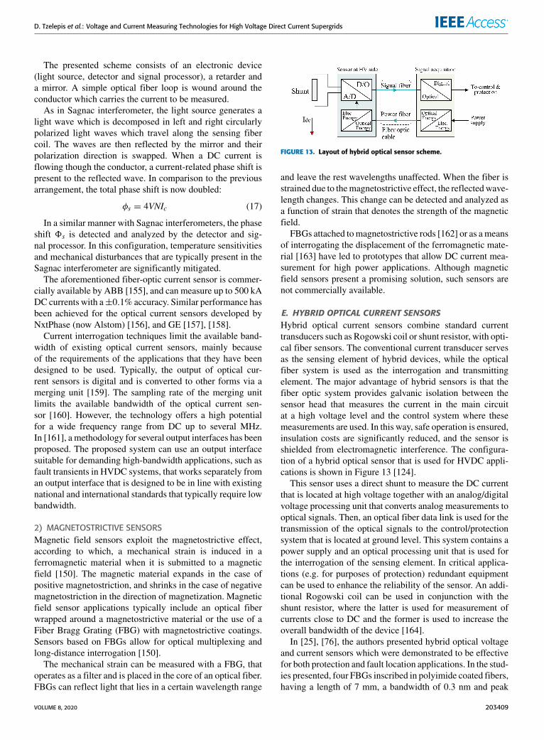
The presented scheme consists of an electronic device(light source, detector and signal processor), a retarder anda mirror. A simple optical fiber loop is wound around theconductor which carries the current to be measured.
As in Sagnac interferometer, the light source generates alight wave which is decomposed in left and right circularlypolarized light waves which travel along the sensing fibercoil. The waves are then reflected by the mirror and theirpolarization direction is swapped. When a DC current isflowing though the conductor, a current-related phase shift ispresent to the reflected wave. In comparison to the previousarrangement, the total phase shift is now doubled:
φs = 4VNIc (17)
In a similar manner with Sagnac interferometers, the phaseshift 8s is detected and analyzed by the detector and sig-nal processor. In this configuration, temperature sensitivitiesand mechanical disturbances that are typically present in theSagnac interferometer are significantly mitigated.
The aforementioned fiber-optic current sensor is commer-cially available by ABB [155], and can measure up to 500 kADC currents with a±0.1% accuracy. Similar performance hasbeen achieved for the optical current sensors developed byNxtPhase (now Alstom) [156], and GE [157], [158].
Current interrogation techniques limit the available band-width of existing optical current sensors, mainly becauseof the requirements of the applications that they have beendesigned to be used. Typically, the output of optical cur-rent sensors is digital and is converted to other forms via amerging unit [159]. The sampling rate of the merging unitlimits the available bandwidth of the optical current sen-sor [160]. However, the technology offers a high potentialfor a wide frequency range from DC up to several MHz.In [161], a methodology for several output interfaces has beenproposed. The proposed system can use an output interfacesuitable for demanding high-bandwidth applications, such asfault transients in HVDC systems, that works separately froman output interface that is designed to be in line with existingnational and international standards that typically require lowbandwidth.
2) MAGNETOSTRICTIVE SENSORSMagnetic field sensors exploit the magnetostrictive effect,according to which, a mechanical strain is induced in aferromagnetic material when it is submitted to a magneticfield [150]. The magnetic material expands in the case ofpositive magnetostriction, and shrinks in the case of negativemagnetostriction in the direction of magnetization. Magneticfield sensor applications typically include an optical fiberwrapped around a magnetostrictive material or the use of aFiber Bragg Grating (FBG) with magnetostrictive coatings.Sensors based on FBGs allow for optical multiplexing andlong-distance interrogation [150].
The mechanical strain can be measured with a FBG, thatoperates as a filter and is placed in the core of an optical fiber.FBGs can reflect light that lies in a certain wavelength range
FIGURE 13. Layout of hybrid optical sensor scheme.
and leave the rest wavelengths unaffected. When the fiber isstrained due to themagnetostrictive effect, the reflectedwave-length changes. This change can be detected and analyzed asa function of strain that denotes the strength of the magneticfield.
FBGs attached tomagnetostrictive rods [162] or as ameansof interrogating the displacement of the ferromagnetic mate-rial [163] have led to prototypes that allow DC current mea-surement for high power applications. Although magneticfield sensors present a promising solution, such sensors arenot commercially available.
E. HYBRID OPTICAL CURRENT SENSORSHybrid optical current sensors combine standard currenttransducers such as Rogowski coil or shunt resistor, with opti-cal fiber sensors. The conventional current transducer servesas the sensing element of hybrid devices, while the opticalfiber system is used as the interrogation and transmittingelement. The major advantage of hybrid sensors is that thefiber optic system provides galvanic isolation between thesensor head that measures the current in the main circuitat a high voltage level and the control system where thesemeasurements are used. In this way, safe operation is ensured,insulation costs are significantly reduced, and the sensor isshielded from electromagnetic interference. The configura-tion of a hybrid optical sensor that is used for HVDC appli-cations is shown in Figure 13 [124].
This sensor uses a direct shunt to measure the DC currentthat is located at high voltage together with an analog/digitalvoltage processing unit that converts analog measurements tooptical signals. Then, an optical fiber data link is used for thetransmission of the optical signals to the control/protectionsystem that is located at ground level. This system contains apower supply and an optical processing unit that is used forthe interrogation of the sensing element. In critical applica-tions (e.g. for purposes of protection) redundant equipmentcan be used to enhance the reliability of the sensor. An addi-tional Rogowski coil can be used in conjunction with theshunt resistor, where the latter is used for measurement ofcurrents close to DC and the former is used to increase theoverall bandwidth of the device [164].
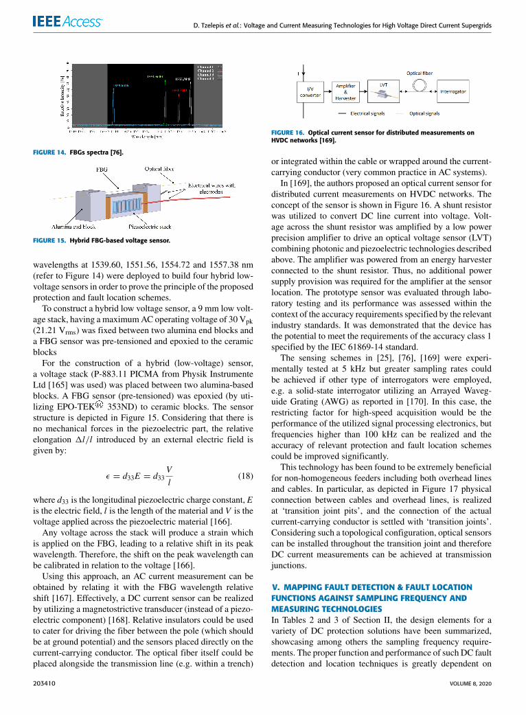
In [25], [76], the authors presented hybrid optical voltageand current sensors which were demonstrated to be effectivefor both protection and fault location applications. In the stud-ies presented, four FBGs inscribed in polyimide coated fibers,having a length of 7 mm, a bandwidth of 0.3 nm and peak
VOLUME 8, 2020 203409
D. Tzelepis et al.: Voltage and Current Measuring Technologies for High Voltage Direct Current Supergrids
FIGURE 14. FBGs spectra [76].
FIGURE 15. Hybrid FBG-based voltage sensor.
wavelengths at 1539.60, 1551.56, 1554.72 and 1557.38 nm(refer to Figure 14) were deployed to build four hybrid low-voltage sensors in order to prove the principle of the proposedprotection and fault location schemes.
To construct a hybrid low voltage sensor, a 9 mm low volt-age stack, having a maximumAC operating voltage of 30 Vpk(21.21 Vrms) was fixed between two alumina end blocks anda FBG sensor was pre-tensioned and epoxied to the ceramicblocks
For the construction of a hybrid (low-voltage) sensor,a voltage stack (P-883.11 PICMA from Physik InstrumenteLtd [165] was used) was placed between two alumina-basedblocks. A FBG sensor (pre-tensioned) was epoxied (by uti-lizing EPO-TEK® 353ND) to ceramic blocks. The sensorstructure is depicted in Figure 15. Considering that there isno mechanical forces in the piezoelectric part, the relativeelongation 1l/l introduced by an external electric field isgiven by:
ε = d33E = d33Vl
(18)
where d33 is the longitudinal piezoelectric charge constant, Eis the electric field, l is the length of the material and V is thevoltage applied across the piezoelectric material [166].
Any voltage across the stack will produce a strain whichis applied on the FBG, leading to a relative shift in its peakwavelength. Therefore, the shift on the peak wavelength canbe calibrated in relation to the voltage [166].
Using this approach, an AC current measurement can beobtained by relating it with the FBG wavelength relativeshift [167]. Effectively, a DC current sensor can be realizedby utilizing a magnetostrictive transducer (instead of a piezo-electric component) [168]. Relative insulators could be usedto cater for driving the fiber between the pole (which shouldbe at ground potential) and the sensors placed directly on thecurrent-carrying conductor. The optical fiber itself could beplaced alongside the transmission line (e.g. within a trench)
FIGURE 16. Optical current sensor for distributed measurements onHVDC networks [169].
or integrated within the cable or wrapped around the current-carrying conductor (very common practice in AC systems).
In [169], the authors proposed an optical current sensor fordistributed current measurements on HVDC networks. Theconcept of the sensor is shown in Figure 16. A shunt resistorwas utilized to convert DC line current into voltage. Volt-age across the shunt resistor was amplified by a low powerprecision amplifier to drive an optical voltage sensor (LVT)combining photonic and piezoelectric technologies describedabove. The amplifier was powered from an energy harvesterconnected to the shunt resistor. Thus, no additional powersupply provision was required for the amplifier at the sensorlocation. The prototype sensor was evaluated through labo-ratory testing and its performance was assessed within thecontext of the accuracy requirements specified by the relevantindustry standards. It was demonstrated that the device hasthe potential to meet the requirements of the accuracy class 1specified by the IEC 61869-14 standard.
The sensing schemes in [25], [76], [169] were experi-mentally tested at 5 kHz but greater sampling rates couldbe achieved if other type of interrogators were employed,e.g. a solid-state interrogator utilizing an Arrayed Waveg-uide Grating (AWG) as reported in [170]. In this case, therestricting factor for high-speed acquisition would be theperformance of the utilized signal processing electronics, butfrequencies higher than 100 kHz can be realized and theaccuracy of relevant protection and fault location schemescould be improved significantly.
This technology has been found to be extremely beneficialfor non-homogeneous feeders including both overhead linesand cables. In particular, as depicted in Figure 17 physicalconnection between cables and overhead lines, is realizedat ‘transition joint pits’, and the connection of the actualcurrent-carrying conductor is settled with ‘transition joints’.Considering such a topological configuration, optical sensorscan be installed throughout the transition joint and thereforeDC current measurements can be achieved at transmissionjunctions.
V. MAPPING FAULT DETECTION & FAULT LOCATIONFUNCTIONS AGAINST SAMPLING FREQUENCY ANDMEASURING TECHNOLOGIESIn Tables 2 and 3 of Section II, the design elements for avariety of DC protection solutions have been summarized,showcasing among others the sampling frequency require-ments. The proper function and performance of such DC faultdetection and location techniques is greatly dependent on
203410 VOLUME 8, 2020

D. Tzelepis et al.: Voltage and Current Measuring Technologies for High Voltage Direct Current Supergrids
FIGURE 17. Typical outline of a transition joint pit [25].
the quality of measurements fed to the protection and faultlocation devices by the corresponding measuring schemes.This calls for an appraisal of the capabilities of existingvoltage and currents measuring devices in terms of bandwidthrequirements for the state-of-the-art DC fault location anddetection functions.
With respect to voltage measurements, there is a limitednumber of options (refer to Section III). These mainly com-prise of the RC voltage divider that achieves a high bandwidthin the order ofMHz, and the hybrid optical voltage sensor thatmay emerge in future applications. The superior frequencyresponse of the former, combined with its relative maturity,have rendered RC-voltage divider the main technology usedin HVDC applications. By inspecting the frequency require-ments of the various voltage-based DC fault detection andlocation functions, it is observed that they fall within theavailable bandwidth of RC-voltage divider. Hence, it can beconcluded that voltage measurements for HVDC applicationsare considered readily accessible, indicating a competitiveadvantage of protection and fault location solutions that arebased exclusively on voltage signals.
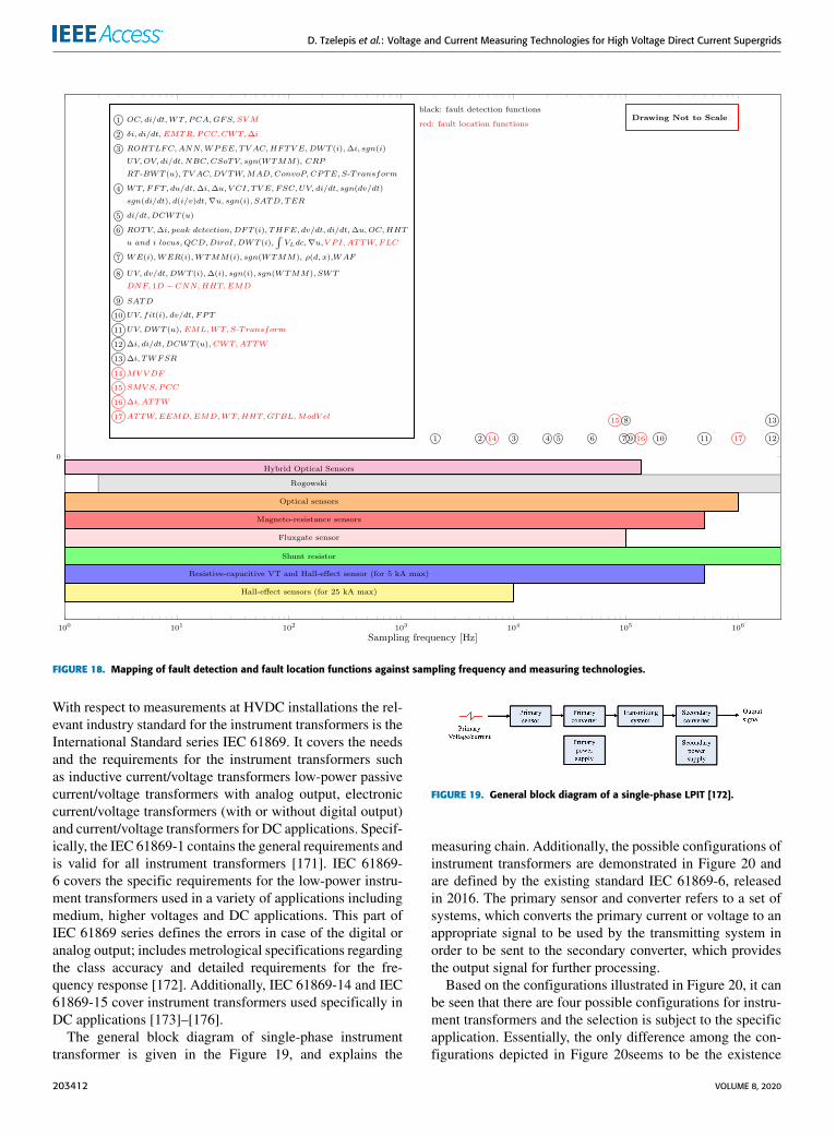
For current measurements, there is wider range of options,with each technology occupying a different frequency spec-trum. In Figure 18, the current-based fault detection andlocation functions aremapped on a frequency diagram againstthe available current measuring techniques to illustrate thepotential for applicability based on the existing technologies.It is worth noting that the frequency range achieved by eachcurrent sensing scheme, mainly refers to the bandwidth ofthe primary sensor, whereas the overall bandwidth of thecomplete measuring system may be further restricted by thesecondary converter, the corresponding data acquisition sys-tem and signal-processing electronics.
An initial analysis of the diagram reveals a distinctivedifference in the frequency range between DC fault detec-tion and DC fault location functions. It is evident that themajority of DC fault detection solutions is concentrated ina frequency spectrum ranging from a few kHz to 100 kHz.This is explained by the fact that DC fault detection aimsto detect every probable fault within the relay’s protectionzone, without the need for extremely accurate capture offast transients during DC faults and therefore, high sampling
frequencies are not typically required. This is especially truefor unit protection schemes, which very often rely on sim-plified means of comparison between current measurementsfrom both ends of the protected transmission medium. Onthe contrary, the vast majority of fault location functionsutilizes sampling frequencies in the range of 100 kHz to2 MHz. This is attributed to the fact that enhanced accuracyin fault location estimation is of paramount importance toexpedite post-fault maintenance and reduce the downtime ofthe faulted component (e.g. DC cable). Hence, fault locationmethods require finer capture of fault transients, resulting inthe utilization of significantly higher sampling frequencies.
Based on these findings, it is evident that there is greatervariety of options among current measuring technologies forsupporting current-based DC fault detection functions. In thiscase, the selection of the appropriate measuring instrumentcan be realized according to the sensor’s reliability, accu-racy, longevity, dynamic range, size and weight concerns,cost etc., while it is likely that there might be multiple cur-rent sensors that satisfy the required performance criteria.In the case of fault location functions with increased samplingrates, it can be seen from the diagram that the availablesensors with the capability to measure faster fault transientsare significantly reduced. It is noteworthy that group 12©approaches the bandwidth capacity limit of existing currentinstruments. Moreover, applications with high sampling ratesare also accompanied with increased requirements in termsof signal processing electronics and advanced output inter-faces, noise resilience, reliability and inevitably cost. There-fore, the implementation of such high-bandwidth demandingapplications with suitable current instruments is a more com-plex task.
Taking Wavelet Transform (WT) and its variants (i.e.DWT, CWT, SWT) as an example, it can be noticed from thediagram that they are used as the main function in several DCfault detection algorithms (groups 1©- 8©), in which samplingfrequencies are in most cases less or equal than 100 kHz.In addition, the same functions have been employed in severaloccasions for fault location purposes (groups 2© 11©, 12© and17©), in which the vast majority utilizes significantly highersampling rates. Since DC protection and DC fault locationare anticipated to be integral parts of future HVDC grids andgiven that voltage and/or current measurements are requiredin both cases, it is reasonable to assume that the measuringinstruments will be shared for the purposes of both applica-tions. Therefore, a convergence between the requirements ofboth applications is desired, especially in terms of samplingfrequency. Based on the diagram, such a convergence seemsto be achieved for sampling frequencies around 100 kHzthat concentrate a significant proportion of the detection andlocation functions.
VI. INDUSTRY STANDARDSA. IEC 61869Voltage and current sensors are key components for realizinghigh-fidelity measuring voltage and current measurements.
VOLUME 8, 2020 203411
D. Tzelepis et al.: Voltage and Current Measuring Technologies for High Voltage Direct Current Supergrids
FIGURE 18. Mapping of fault detection and fault location functions against sampling frequency and measuring technologies.
With respect to measurements at HVDC installations the rel-evant industry standard for the instrument transformers is theInternational Standard series IEC 61869. It covers the needsand the requirements for the instrument transformers suchas inductive current/voltage transformers low-power passivecurrent/voltage transformers with analog output, electroniccurrent/voltage transformers (with or without digital output)and current/voltage transformers for DC applications. Specif-ically, the IEC 61869-1 contains the general requirements andis valid for all instrument transformers [171]. IEC 61869-6 covers the specific requirements for the low-power instru-ment transformers used in a variety of applications includingmedium, higher voltages and DC applications. This part ofIEC 61869 series defines the errors in case of the digital oranalog output; includes metrological specifications regardingthe class accuracy and detailed requirements for the fre-quency response [172]. Additionally, IEC 61869-14 and IEC61869-15 cover instrument transformers used specifically inDC applications [173]–[176].
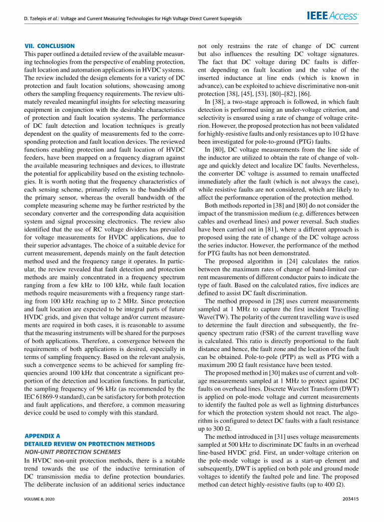
The general block diagram of single-phase instrumenttransformer is given in the Figure 19, and explains the
FIGURE 19. General block diagram of a single-phase LPIT [172].
measuring chain. Additionally, the possible configurations ofinstrument transformers are demonstrated in Figure 20 andare defined by the existing standard IEC 61869-6, releasedin 2016. The primary sensor and converter refers to a set ofsystems, which converts the primary current or voltage to anappropriate signal to be used by the transmitting system inorder to be sent to the secondary converter, which providesthe output signal for further processing.
Based on the configurations illustrated in Figure 20, it canbe seen that there are four possible configurations for instru-ment transformers and the selection is subject to the specificapplication. Essentially, the only difference among the con-figurations depicted in Figure 20seems to be the existence
203412 VOLUME 8, 2020

D. Tzelepis et al.: Voltage and Current Measuring Technologies for High Voltage Direct Current Supergrids
FIGURE 20. General block diagrams of possible configurations of voltageand current transformer for DC applications [173], [174].
of electronics with instrument transformers in form of eitherprimary or secondary converter. The transmission link whichcan be either electronic (copper wires and Modbus protocol)or optical link to transmit the measurement data to relaysor control rooms. This would also include electronic trans-formers with digital output covered by IEC 60044-7 [177](replaced by IEC 61869).
For example, configuration 1 in Figure 20 is compliantwith IEC 61869-10 and IEC 61869-11, which covers the addi-tional requirements for low-power passive current (LPCTs)and voltage transformers (LPVTs), respectively. They areapplicable to low-power passive instrument transformers withanalog output, used for electrical measurements or electri-cal protection devices of the power systems [178], [179].Configurations 2 and 3 could be used in applications, wheresignals should be further processed or converted prior to anyprocessing by IEDs, merging units, etc. Configuration 4, forexample, would be more applicable for sensors connected tomerging units (where again analogue signals are convertedto digital signals and transmitted to merging units usingSampled Values and GOOSE messages.
IEC 61869-10, released in 2017, covers the low-powerpassive current transformers with magnetic core or core-lesslike Rogowski coil, installed around the primary conductor.Their output can be either proportional to the primary current,or to the derivative of the primary current [178]. Passivecurrent transformers do not include any active electroniccomponents, which means that they do not use active primaryconverter (IEC 61869-8 refers to the electronic current trans-formers with active electronics). As per the Configuration1 depicted in Figure 20, the primary power supply, secondaryconverter and the secondary power supply are not consid-ered. In the case of the derivative LPCT, the air-core coil
(Rogowski coil) is used as primary sensor and a transmissionsystem is considered as well, while the primary converteris omitted. However, in the case of the proportional LPCT,the primary sensor corresponds to a ferromagnetic-core coil,and as primary converter a burden resistance connected tothe coil output can be used. Specifically, proportional LPCTis composed of an inductive current transformer with pri-mary winding, small core and secondary winding connecteddirectly to a shunt resistor. Within this configuration a trans-mission system is utilized as well.
IEC 61869-11 covers the needs and requirements of theLPVTs without active electronics, which depend on the volt-age divider principle. The voltage measurements are basedon two working principles namely resistive and capacitivedividers. The output voltage of the voltage divider is substan-tially proportional to the primary voltage. The general blockdiagram of the single phase LPVTS corresponds to Configu-ration 1 in Figure 20, as it includes the primary voltage sensor,the passive primary converter and the transmitting cable.The secondary converter and power supplies are neglected,similarly to the LPCT configuration.
The requirements of the newly-manufactured instrumenttransformers anticipated to be used in DC applications, forvoltages above 1.5 kV, are covered by the IEC 61869-14 andIEC-61869-15, in conjunction with IEC 61869-6 and IEC61869-1 [171]–[176].
IEC 61869-14 and IEC 61869-15 are applicable to thecurrent and voltage transformers for DC applications respec-tively (i.e. DCCTs and DCVTs) [173]–[176]. Such instru-ment transformers are composed by the primary sensors (withoptional primary electronics), the transmitting system and themerging unit (refer to Configuration 4 in Figure 20). Theprimary converter is used to convert the primary, high ampli-tude signal to lower amplitude signal, which can be analog ordigital, providing the input signal for the merging unit. Thissignal can be then converted to analog or digital format bythe merging unit and it is sent to be further processed by thecorresponding IED.
For voltage measurements, the primary sensor are resis-tive voltage dividers and mainly the RC dividers which canachieve the highest bandwidth (i.e. in the order of MHz).The primary element includes capacitive elements connectedin series, and parallel to several resistors, which form theRC units. The secondary part includes the same type of ele-ments (i.e. capacitors and resistors) connected in parallel butwith different values in order to achieve the desired voltageratio. It shall be noted that hybrid optical voltage sensors areexpected to be used in the futureDC applications [174], [176].
With specific reference to DC protection and fault loca-tion applications, the IEC 61869-9 promotes the samplingfrequency of 96 kHz. However, the research investigating itsperformance and suitability is limited and has been reportedin [41], [42], [180]. Within these studies it has been reportedthat a sampling frequency of 96 kHz is adequate for capturingDC-side fault transients and therefore can be utilized forprotection purposes.
VOLUME 8, 2020 203413

D. Tzelepis et al.: Voltage and Current Measuring Technologies for High Voltage Direct Current Supergrids
B. FURTHER RELEVANT STANDARDSRecently, the HVDC digital substation concept is gainingattention, which is inspired by the approach followed inAC digital substations using the IEC 61850 standard series.In HVDC digital substations, current and voltage sensorsare interfaced with merging units, which are responsiblefor converting and transmitting the measured voltage andcurrent values to the various protection and control devices.IEC 61850-9-1 [181] and IEC 61850-9-2 [182] specify thatsampled values (voltage and/or current measurements) aretransmitted by the merging unit to the corresponding IEDs(through an intermediary process bus) at a rate of 80 samplesper cycle for protection applications.
It is likely that a standard that will be an adaptation of IEC61850 [183] may emerge for HVDC substations. Neverthe-less, the communication rate of sampled values should beadjusted to satisfy the critical requirement for increased pro-tection speed in HVDC grids, and to ensure agreement withthe proposed sampling frequency by IEC 61869. For com-munication of teleprotection signals between different HVDCsubstations, the guidelines provided by IEC 60834 [184] onteleprotection equipment of power systems can be followed.
Best practices for improved reliability of critical substationfunctions would require duplication of certain equipment,such as Ethernet switches, and the use of communicationsprotocols which manage redundant data streams. Guidanceis given in IEC 62439-3:2020 [185]. Furthermore, provisionsfor digital substation cybersecurity are given in the IEC62351 [186] series of standards.
A new edition of an IEC Technical Report (TR), IEC TR61850-90-14 Edition 1 [187], is presently being drafted toguide the use of the IEC 61850 standards for HVDC tech-nologies and Flexible AC Transmission Systems (FACTS)devices. This includes the use of IEC 61850 communicationsand data models for implementing control and protectionsystems for FACTS and HVDC, such as power oscillationdamping control and fast-acting protective devices.
C. IMPACT OF COMMUNICATIONS SYSTEMS1) OVERVIEWHVDC protection and control applications may require inputsignals from multiple distributed measurement locations.FBG-based measurement methods can multiplex multiplevoltage and current measurements on a single fiber to acentral protection and control device [76]. Other sensor typestypically require a communications network to transfer dig-itized measurement data, which could result in time delaysand other undesirable impacts. Furthermore, the impact ofcommunications on HVDC operation will depend on spe-cific protection and control requirements, approaches, andalgorithms. However, this section provides a general-purposereview of this impact.
The digitalization of measurements is increasingly beingimplemented in AC substations for increased efficiency,increased real-time performance, and reduced through-life
FIGURE 21. Generic representation of HVDC digital substationcommunications.
costs, and this approach could also be applied in DC sub-stations. However, as noted in Section VI-A, DC monitoringsystems may require relatively high sampling rates to captureall relevant electrical transient phenomena, compared withtypical AC system requirements. A sampling rate of 96 kHz,as defined in IEC 61869-9, is suitable for many DC applica-tions, with the exception of detailed fault location, as identi-fied in Section V.
2) EXAMPLE APPLICATIONFigure 21 illustrates a generic HVDC digital substation, withthree DC feeders. Each feeder has a Merging Unit (MU) todigitize voltage and current measurements, and potentially tocontrol a local circuit breaker based on a coordinated com-mand from a central protection or control system.AnEthernetnetwork is used to transfer digitized measurements betweendevices. Note that it is possible for the MU to be integrateddirectly within the AC-DC converter, which would enableadditional real-time protection and control functionality bycommunicating with the local power electronic convertercontrol system.
Work conducted in [42] presents a method for calculatingthe maximum intrinsic measurement and communicationsdelay, although excluding additional processing required bythe sending and receiving devices, algorithm processing time,and time synchronization error. Based on the analysis in [37],the minimum delay for transfer of digitized measurementfrom the MU to the central controller is 36.06 µs (assuminga maximum of three ‘‘competing’’ simultaneous packets).Similarly, the minimum delay for a control command fromthe central controller to a MU, assuming a similar mes-sage size, is at least 25.64 µs (36.06 µs minus the 96 kHzsampling time of 10.42 µs), resulting in a total end-to-endcommunications delay of 61.7 µs. Note that this excludes theexecution time for application-specific control or protectionprocessing, and will vary based on the performance of thecontroller platform. Each additional MU would add at leastapproximately 10.78 µs (0.7 µs for a single Ethernet linktransmission, 0.58 µs for additional switch queuing, and9.5 µs for decoding the Ethernet frame), as they must bereceived serially by the central controller via its Ethernetconnection; all other aspects contributing to the delay shouldoccur in parallel with the other MUs.
203414 VOLUME 8, 2020
D. Tzelepis et al.: Voltage and Current Measuring Technologies for High Voltage Direct Current Supergrids
VII. CONCLUSIONThis paper outlined a detailed review of the available measur-ing technologies from the perspective of enabling protection,fault location and automation applications in HVDC systems.The review included the design elements for a variety of DCprotection and fault location solutions, showcasing amongothers the sampling frequency requirements. The review ulti-mately revealed meaningful insights for selecting measuringequipment in conjunction with the desirable characteristicsof protection and fault location systems. The performanceof DC fault detection and location techniques is greatlydependent on the quality of measurements fed to the corre-sponding protection and fault location devices. The reviewedfunctions enabling protection and fault location of HVDCfeeders, have been mapped on a frequency diagram againstthe available measuring techniques and devices, to illustratethe potential for applicability based on the existing technolo-gies. It is worth noting that the frequency characteristics ofeach sensing scheme, primarily refers to the bandwidth ofthe primary sensor, whereas the overall bandwidth of thecomplete measuring scheme may be further restricted by thesecondary converter and the corresponding data acquisitionsystem and signal processing electronics. The review alsoidentified that the use of RC voltage dividers has prevailedfor voltage measurements for HVDC applications, due totheir superior advantages. The choice of a suitable device forcurrent measurement, depends mainly on the fault detectionmethod used and the frequency range it operates. In partic-ular, the review revealed that fault detection and protectionmethods are mainly concentrated in a frequency spectrumranging from a few kHz to 100 kHz, while fault locationmethods require measurements with a frequency range start-ing from 100 kHz reaching up to 2 MHz. Since protectionand fault location are expected to be integral parts of futureHVDC grids, and given that voltage and/or current measure-ments are required in both cases, it is reasonable to assumethat themeasuring instruments will be shared for the purposesof both applications. Therefore, a convergence between therequirements of both applications is desired, especially interms of sampling frequency. Based on the relevant analysis,such a convergence seems to be achieved for sampling fre-quencies around 100 kHz that concentrate a significant pro-portion of the detection and location functions. In particular,the sampling frequency of 96 kHz (as recommended by theIEC 61869-9 standard), can be satisfactory for both protectionand fault applications, and therefore, a common measuringdevice could be used to comply with this standard.
APPENDIX ADETAILED REVIEW ON PROTECTION METHODSNON-UNIT PROTECTION SCHEMESIn HVDC non-unit protection methods, there is a notabletrend towards the use of the inductive termination ofDC transmission media to define protection boundaries.The deliberate inclusion of an additional series inductance
not only restrains the rate of change of DC currentbut also influences the resulting DC voltage signatures.The fact that DC voltage during DC faults is differ-ent depending on fault location and the value of theinserted inductance at line ends (which is known inadvance), can be exploited to achieve discriminative non-unitprotection [38], [45], [53], [80]–[82], [86].
In [38], a two-stage approach is followed, in which faultdetection is performed using an under-voltage criterion, andselectivity is ensured using a rate of change of voltage crite-rion. However, the proposed protection has not been validatedfor highly-resistive faults and only resistances up to 10� havebeen investigated for pole-to-ground (PTG) faults.
In [80], DC voltage measurements from the line side ofthe inductor are utilized to obtain the rate of change of volt-age and quickly detect and localize DC faults. Nevertheless,the converter DC voltage is assumed to remain unaffectedimmediately after the fault (which is not always the case),while resistive faults are not considered, which are likely toaffect the performance operation of the protection method.
Both methods reported in [38] and [80] do not consider theimpact of the transmission medium (e.g. differences betweencables and overhead lines) and power reversal. Such studieshave been carried out in [81], where a different approach isproposed using the rate of change of the DC voltage acrossthe series inductor. However, the performance of the methodfor PTG faults has not been demonstrated.
The proposed algorithm in [24] calculates the ratiosbetween the maximum rates of change of band-limited cur-rent measurements of different conductor pairs to indicate thetype of fault. Based on the calculated ratios, five indices aredefined to assist DC fault discrimination.
The method proposed in [28] uses current measurementssampled at 1 MHz to capture the first incident TravellingWave(TW). The polarity of the current travellingwave is usedto determine the fault direction and subsequently, the fre-quency spectrum ratio (FSR) of the current travelling waveis calculated. This ratio is directly proportional to the faultdistance and hence, the fault zone and the location of the faultcan be obtained. Pole-to-pole (PTP) as well as PTG with amaximum 200 � fault resistance have been tested.
The proposedmethod in [30]makes use of current and volt-age measurements sampled at 1 MHz to protect against DCfaults on overhead lines. Discrete Wavelet Transform (DWT)is applied on pole-mode voltage and current measurementsto identify the faulted pole as well as lightning disturbancesfor which the protection system should not react. The algo-rithm is configured to detect DC faults with a fault resistanceup to 300 �.
The method introduced in [31] uses voltage measurementssampled at 500 kHz to discriminate DC faults in an overheadline-based HVDC grid. First, an under-voltage criterion onthe pole-mode voltage is used as a start-up element andsubsequently, DWT is applied on both pole and ground modevoltages to identify the faulted pole and line. The proposedmethod can detect highly-resistive faults (up to 400 �).
VOLUME 8, 2020 203415
D. Tzelepis et al.: Voltage and Current Measuring Technologies for High Voltage Direct Current Supergrids
The method proposed in [32] uses an under-voltage cri-terion to detect every probable DC fault and the First PeakTime (FPT) of the line-mode component of the DC voltageto discriminate between internal and external faults. FPT isdefined as the time instant at which the DC voltage is at itsminimum. In addition, the faulted-pole is identified using thesign of the ground-mode component of the DC line voltage.For the operation of the scheme, DC voltage measurementsare required with 200 kHz sampling frequency. The methodhas been tested for both PTP and PTG faults with faultsresistances of up to 500 �.
The methods proposed in [33], [34], use current measure-ments (sampled at 200 kHz) for the first ms of the transientperiod of the DC fault to obtain a time-domain fitting of thefault current. The fitting coefficients are used as an indica-tor for discriminating between external and internal faults.Because the method fails to detect close-up faults, an under-voltage criterion is also employed to protect against suchfaults. The method has been tested for up to 1000 � faultresistance. In further work in [35], the fitting coefficientsof the zero-sequence current are used to reflect the faultimpedance and fault distance of PTG faults in OHL-basedHVDC systems. Based on the rough estimation of theseparameters, voltage derivative with an adaptive threshold isused for DC fault detection and discrimination. The methodutilizes 200 kHz sampling frequency, while faults with resis-tance up to 300 � have been tested.The proposed method in [36] utilizes current and voltage
measurements captured at 110 kHz to derive the differencebetween the 0-mode and 1-mode surge arrival time of trav-elling waves. The proposed scheme has been tested for PTGfaults with fault resistance of up to 200 �.
In [37], a generalized methodology specifically tailored forHVDC grid non-unit protection purposes is developed forflexibly deriving the key parameters for WT-based protec-tion solutions. Among the various WT variants, StationaryWavelet Transform (SWT) is selected and applied on DCvoltage measurements (sampled at 100 kHz) to detect anddiscriminate between internal and external DC faults. In addi-tion, current derivative is employed to differentiate betweenbackward and forward faults. The method has been testedfor both PTP and PTG faults, and it has been shown thatit can detect internal DC faults with more than 500 � faultresistance.
The proposed scheme in [41] is based on instantaneouscurrent measurements, which are obtained from all DC linesand the converter that are connected to a DC busbar. Subse-quently, the measurements are analyzed through dyadic sub-band tree structures in order to extract specific features, suchas wavelet energy, polarity, and wavelet energy ratios. Theprotection scheme integrates a power restoration module thatre-energizes the converter and restores the power to pre-faultvalue.
The scheme presented in [42] utilizes local current andvoltage measurements from all transmission lines con-nected to the same DC busbar in conjunction with DC-side
converter current measurements. The proposed scheme oper-ates at a sampling rate of 96 kHz which is compliant withIEC 61869-9. The faulted line is discriminated by wavelettransform of line voltage traces, while DC busbar faults aredetected by the principle of instantaneous current differential.The scheme has been validated both for PTG and PTP faultswith up to 500 � fault resistance.In [43], a distance protection method is developed based on
voltage and current measurements sampled at 50 kHz. Theproposed solution makes use of a combined under-voltageand current derivative criterion to detect DC faults, whilealso the sign of the latter is used to differentiate betweenbackward and forward faults. Discrimination between for-ward internal and forward external faults is accomplished byapplying Hilbert-Huang Transformation (HHT) on a 4 msdata window in order to extract the DC voltage transientfrequency, which in turn serves as a measure of the faultdistance. The method has been tested only for PTP faults withsmall fault resistances.
Another method is proposed in [44] based on bus andline current measurements (50 kHz sampling frequency. Thescheme requires communication on bus-level for fault dis-crimination and selective tripping of circuit breakers (CBs).
In [45], voltage measurements from both sides of theinductive termination are used to calculate the ratio of tran-sient voltages and design a protection method. The method isable to achieve fault sensitivity and selectivity for solid andhighly-resistive faults with fault resistances of up to 200 �.
The method introduced in [46] utilizes current measure-ments captured at 50 kHz to perform DFT and extract thehigh frequency components. The discrimination betweenexternal and internal faults is based on the fact that high-frequency components of the fault current flow through thefaulted line and then significantly decay in adjacent healthylines. The scheme has been tested for highly-resistive faultsup to 300 �.
The method described in [48] is suitable for parallel-connected MTDC grids and is based upon the change rateof the current travelling waves. For the implementation ofthe algorithm, current and voltage measurements sampled at50 kHz are required. In the presented studies, fault resistancesof up to 100 � have been considered.
The non-unit method presented in [52] relies on currentderivative to determine the DC fault direction and onWaveletTransform Modulus Maxima (WTMM) of the first incidentvoltage travelling wave to discriminate between external andinternal faults. The transfer function of the voltage at themeasurement point with respect to the actual fault loca-tion is derived to calculate the protection threshold. Thescheme utilizes a sampling frequency of 25 kHz and has beentested for both PTP and PTG faults with fault resistancesup to 500 �.
The work presented in [53] utilizes voltage measurements(sampled at 25 kHz) at both sides of current-limiting induc-tors in bipole HVDC grids with a metallic return conductor.The rate of change is adopted to construct a directional-based
203416 VOLUME 8, 2020
D. Tzelepis et al.: Voltage and Current Measuring Technologies for High Voltage Direct Current Supergrids
protection in order to distinguish between external and inter-nal DC faults. The protection scheme has been tested withboth PTG and PTP faults with resistance up to 200 �.
In [55], a two-stage approach is proposed based on cur-rent and voltage measurements to detect DC faults in multi-terminal HVDC networks. Initially, the DC fault is indicatedby detecting travelling waves with the use of wavelet trans-form. The next stage is the fault location element that is basedon the characteristic harmonic of the current. The proposedprotection method utilizes very complex mathematical oper-ations while current interruption devices and highly-resistivefaults (higher than 100 �) are not investigated.
The method introduced in [56] utilizes voltage measure-ments (captured at 20 kHz) to calculate the voltage derivative,voltage change integrals and transient voltage energy. Theproposedmethod has been tested for both PTP and PTG faultswith fault resistance of up to 200 �.
The method presented in [57] utilizes current and voltagemeasurements captured at 20 kHz to calculate the currentand voltage derivative, and the rate of change of the cur-rent to voltage ratio. The former two are used as start-upand security elements, while the latter is used for fault dis-crimination. Both PTG and to PTP faults have been tested.However, the method requires a minimum DC inductor sizefor its proper operation and is sensitive to highly-resistivefaults.
The primary protection method described in [58] usesvoltage measurements sampled at 20 kHz to discriminate DCfaults in a HVDC grid with overhead lines. Initially, voltagegradient is used as a protection start-up element and then,the difference between the surge arrival time of zero-modeand line-mode travelling waves is calculated to determine thefault direction. Subsequently, voltage derivative is adoptedto discriminate between forward internal and external faults.The proposed scheme has been tested for PTG and PTP faultswith fault resistance up to 200 �.
In [59], a protection method is developed based on currentmeasurements sampled at 20 kHz. A transformation matrixis applied on single-end current measurements of both polesto obtain the common- and differential-mode components.Subsequently, the derivative of both current components isutilized to identify the faulted pole and discriminate inter-nal faults, while the polarity of both components is used toexclude backward faults. The method has been tested for bothPTP and PTG faults with resistance up to 300 �.
The protection scheme introduced in [61] utilizes voltageand current measurements (captured at 10 kHz) to calcu-late the current and voltage derivative, under-voltage and toquantify a metric for the Current Reduction Phenomenon(CRP) (i.e. short periods in which line current reduces due towave reflections at the fault point). Under-voltage and currentderivative are initially used for fault detection and discrimi-nation between forward/backward faults, respectively. Subse-quently, voltage derivative is used as the main discriminationfunction and CRP is introduced to enhance the sensitivity ofthe method against highly-resistive faults. The method has
been tested for PTP and PTG faults with a range of 0-800 �fault resistance.
The authors in [62] propose a non-unit protection methodfor HVDC grids that integrate hybrid MMCs. A DC faultis initially detected based on over-current or under-voltage(voltages and currents sampled at 10 kHz). Afterwards,the increased controllability of the hybrid MMC is exploitedto inject sinusoidal signals (with different frequencies) intothe DC lines of the network, and the fault distance is approx-imated based on a set of equations that describe the sys-tem response to the injected signals. The method is able ofdetecting both PTP and PTG faults with up to 200 � faultresistance.
The protection method proposed in [63] uses current andvoltage measurements sampled at 10 kHz to detect and dis-criminate DC faults in hybrid LCC-VSC multiterminal sys-tems. DWT is used to extract the required specific frequencybands of voltage and current TWs, and construct the convo-lution power that is used for faulted pole and fault directionidentification. Moreover, convolution power-based transientenergy is used to discriminate DC faults. The method hasbeen tested for PTG and PTP faults with fault resistance upto 400 �.In [64], a protection method is proposed using the median
absolute deviation (MAD) of current and voltage to discrim-inate DC faults in multi-terminal HVDC networks. Line-sidevoltage and currents are sampled at 10 kHz. Nevertheless,only solid DC faults haven been investigated.
The method in [65] uses current measurements sampledat 10 kHz to apply S-Transform and extract the high andlow frequency DC current components. The high frequencycontent is used to detect a transient event and the low fre-quency content is used to discriminate DC faults from otherdisturbances. A low voltage experimental test system hasbeen used for the validation of the method and only low faultresistances have been considered.
In [66], real-time boundary wavelet transform (RT-BWT)is applied on voltage measurements across the series inductor(captured at 10 kHz). The algorithm is in effect a modifiedstationary wavelet transform that eliminates the short timedelay that is commonly introduced in other WT variants. Thescheme has been tested for PTP and PTG highly-resistivefaults (up to 300 �).
The method described in [67] uses local-end DC currentmeasurements sampled at 10 kHz. The algorithm dependson the ratio of high-to-low-frequency currents to distinguishinternal from external faults. The low- (0.1–100 Hz) andhigh frequency (>3500 Hz) are deduced over a 5ms timewindow (to avoid the influence of lighting). The protectionscheme detects both PTP and PTG faults with resistances ofup to 200 �.
The proposed method in [68] relies on current measure-ments captured at 10 kHz to derive the transient averagevalue of current. The method deploys analytic expressions ofhigh-frequency equivalent models for the faulted and healthylines to determine the thresholds for protection operation.
VOLUME 8, 2020 203417
D. Tzelepis et al.: Voltage and Current Measuring Technologies for High Voltage Direct Current Supergrids
The scheme has been tested for both PTG and PTP faults withfault resistance of up to 500 �.The scheme presented in [69] calculates the high frequency
transient-voltage energy to determine the faulted section(external or internal fault). The method deploys the Mal-lat algorithm to extract the detailed coefficients at a spe-cific decomposition level and then the peak energy of thedetailed coefficients is obtained. Voltage measurements arecaptured at 10 kHz while the proposed scheme has beentested for both PTP and PTG faults with fault resistance ofup to 300 �.
The scheme presented in [71] is based on artificial neuralnetworks (ANN). In this scheme, high frequency fault currentcomponents are input to ANNs, where they are analyzed inthe frequency domain to extract the signal’s spectral compo-nents. The protection scheme has been tested for PTG andPTP faults with resistance of up to 100 �. The algorithmoperates within a 6-ms time window with signals sampledat 10 kHz.
The method proposed in [73] is based on a Naïve Bayesclassifier, which is utilized to determine voltage and currentthresholds and define the operational time frames for both pri-mary and back-up protection. The proposed scheme requiresDC voltage and current measurements sampled at 10 kHz.The performance of the method has been tested for PTP faultswith resistance up to 10�while PTGDC faults have not beeninvestigated or analyzed at all.
The method described in [74] uses the average value of thefault line current to detect and discriminate DC faults in radialHVDC networks. Moreover, a simplified transient modelis developed and used for the calculation of the protectionthreshold. Current measurements are only required for thisscheme and the sampling frequency is set to 10 kHz.
The scheme presented in [78] is a four-stage protectionalgorithm based on DC over-current, DC current derivative,Wavelet Transform, Principal Component Analysis (PCA),and a Genetic Fuzzy System (GFS). The system utilizescurrent measurements sampled at 2 kHz and requires no com-munication. The scheme performance has been validated forresistance of up to 50�, however after such value its responseseems to be compromised. Another significant drawback ofthis method is the fact that it depends on complicated andnumerous mathematical operations, while there is a need fora training data base.
The method in [82] utilizes local voltage measurements ateither side of current limiting inductors (sampled at 8 kHz)to implement a basic directional element. The same princi-ple is used to develop a slower communication-based DCline protection scheme for detecting highly-resistive faultsup to 200 �.
In [83], the handshaking method is proposed to detectthe DC line in which a fault has occurred. Nevertheless,the method is considered to be relatively slow and AC break-ers are used for DC fault isolation (which can take severalAC cycles and therefore tenths of ms to operate) leading tode-energization of the DC grid.
Travelling wave principles are used in [84] to design amethod that utilizes DC voltage and current derivatives todetermine whether the fault is external or internal. Neverthe-less, this method can be very sensitive to noise and may leadto false protection operation.
The detection method in [85] utilizes a three-stageapproach and a voting scheme to identify and discriminate theexistence and location of faults. The stages include waveletanalysis of DC voltages and currents, as well as voltagederivative and amplitude. However, PTG faults have not beeninvestigated while the protection algorithm appears to berelatively complex and dependent on many parameters, andmay therefore be impractical to implement.
In [86], a primary and secondary protection scheme isproposed. The primary scheme utilizes the voltage across theinductors of both positive and negative DC poles. A trigger isinitiated by an under-voltage criterion on any of the reactorvoltages. Further fault classification is achieved by calculat-ing the differential voltage of the two DC reactors. A back-up scheme is introduced to account for highly-resistive faults.In this case, voltage from both line terminals are required andas such communication is required. Using voltages from bothsides, a directional and a magnitude element are calculatedfrom which the fault is detected and classified. In the studiespresented the DC reactor size is set to 150 mH and theproposed scheme works for DC reactors of up to 30 mH .The needs of sampling frequency have not been specified.In the presented studies resistances of up to 1000� have beenconsidered.
The method described in [87] uses distributed sensorsintegrated in cable joints to provide and construct voltage andcurrent-based superimposed elements. The method combinesa protection algorithm together with proactive hybrid break-ers to increase the speed of operation and achieve increasedperformance. The algorithm has been tested for both PTGand PTP faults with fault resistances in the range of hundredsof ohms. The sampling frequency and time window require-ments haven’t been specified.
The protection strategy proposed in [88] relies on DCcurrent and voltage measurements. The proposed strategyuses AC-side CBs to clear DC-side faults and rapid DCdisconnectors for fault isolation. DC-side faults are detectedby over-current or under-voltage criteria while the faulted lineis discriminated based on two criteria employing DC currentmagnitude and sign. The method is capable of detecting bothPTG and PTP faults. However, the sampling frequency needsare not specified while highly-resistive faults have not beeninvestigated.
The method described in [89] deploys local current andvoltage measurements to realize a protection scheme basedon under-voltage, voltage derivative and current derivative.The scheme presented in [54] relies on current and measure-ments (sampled at 20 kHz) to carry out frequency-spectrumcorrelation and identify the faulted line.
In [93], a protection scheme of overhead line-basedHVDC grids is proposed. First, voltage derivative is used as
203418 VOLUME 8, 2020
D. Tzelepis et al.: Voltage and Current Measuring Technologies for High Voltage Direct Current Supergrids
a start-up element to activate the protection scheme followedby the calculation of the integral of the line-mode and ground-mode components of the voltage across the DC reactor inorder to identify the faulted pole and to discriminate internalfaults, respectively. PTP and PTG faults with fault resistancesof up to 200 � are tested.The protection scheme introduced in [94], uses current
magnitude and current derivative to calculate the currentlimiting reactor power (CLRP). A back-up protection basedon the direction of both currents of the transmission line isalso employed to protect against highly-resistive faults.
In [188], a travelling-wave based direction criterion hasbeen presented that uses DWT to obtain the high frequencycontent of DC voltage and current traces in order to distin-guish between backward and forward faults. The samplingfrequency of this method can be flexibly selected, and 10 kHzwas used for illustration. The sensitivity of the method forforward faults with up to 300 � fault resistance has beendemonstrated.
UNITThere is also a significant number of differential type protec-tion schemes proposed in the open literature [29], [39], [40],[76], [90], [91]. Some of the main drawbacks and challengesassociated with differential protection include the delaysassociated with encoding and decodingmessages, its inherentcommunication time delays, the need for communication pathlatency corrections, and its reliability especially when oneof the measurements is lost or the communications link iscompromised.
In [39] a combined scheme is proposed, which is basedon polarity comparison of initial current travelling wave (forline faults) and on sampled value current differential theory(for DC busbar faults). DC currents (sampled at 100 kHz)from two line ends are utilized to distinguish between internaland external faults by applying the WTMM theory on cur-rent travelling waves. Current differential protection basedon sampled values is achieved over 5 consecutive samplingpoints at 10 kHz. In the presented studies resistances of upto 400 � and resistive superconducting fault current limiters(R-SFCLs) have been used.
In [40], current signals at both line ends are captured andprocessed byDWT in themain protection algorithm. In detail,certain DWT components that are extracted from currentsignals processing at both ends are used to perform energycomparison and achieve discrimination between internal andexternal faults.
The method presented in [50] uses the energy of DWTcoefficients derived from line current measurements sampledat 50 kHz. Moreover, a change in current direction from atleast one of the medium ends needs to be identified in orderto detect an internal fault. Only low resistive PTP faults areinvestigated in this study.
The authors in [51] use voltage gradient to detect a DCfault and comparison of the polarities of the voltage across theDC reactors on both ends of an overhead line to discriminate
between external and internal faults. The selected samplingrate is 50 kHz. The integral of the DC reactor voltage is usedto obtain the polarity. The method has been tested for PTPand PTG fault, and it has been shown that it can identify DCfaults with 400 � fault resistance.In the unit protection scheme that is proposed in [60],
the ratio of transient energy (TER) is calculated at both sidesof the protected medium and used as the main protectionelement. The method has been tested for LCC-based HVDCsystems using current and voltage measurements sampled at20 kHz. In the presented studies, resistances of up to 1000 �have been tested.
In [72], a communication-based scheme is proposed basedon similarity measure of travelling waves. The proposedscheme utilizes voltage and current measurements at bothtransmission line ends, which are analyzed to derive thecosine similarity of backward and forward travelling waves.The scheme has been tested with fault resistances of up to1000 �.The unit protection method introduced in [75] uses current
and voltage measurements (with 20 kHz sampling frequency)of both ends of a transmission line to calculate the differentialvoltage travelling wave in the time domain by means ofconvolution. A method to compensate for out-of-sync datameasurements from the two sides of the line is provided.Moreover, a comprehensive analysis of all sources of timedelay is realized to obtain a total delay time estimation for-mula. The method has been tested for PTG and PTP faults.
In [76], distributed current sensors are placed along thetransmission lines of the HVDC system in order to implementa high-speed differential scheme. In the presented studies,the method has been found to be sensitive, fast, stable duringexternal faults and reliable for both solid and highly-resistiveinternal DC faults.
The authors in [77] use voltage and current measurementssampled at 5 kHz to develop a unit protection method. CosineDistance (CD) is utilized as a metric of similarity between theanalyzed signal and a pre-recorded reference signal to detectforward DC faults. A fault is identified as internal, when thelocal protective relay detects a DC fault, and a fault detectionsignal is received from the protective relay at the remote endof the protection zone. Highly-resistive (up to 100 �) PTPand PTG faults have been considered.
A phase-domain travelling wave differential protectionis presented in [79], in which transmission line modelshave been developed for the application of the protectionscheme using only information contained in the first travel-ling wave. It is worth noting that the required communicationand wave propagation have the same direction, resulting insmaller communication delays than conventional unit pro-tection methods. In addition, a sensitivity analysis of thecable parameters has been realized in [189] to investigate theimpact of potential sources of error on the protection scheme.
The differential protection scheme that is proposed in [90]performs a comparison between the currents of line terminalsfor fault discrimination, while fault isolation is performed
VOLUME 8, 2020 203419
D. Tzelepis et al.: Voltage and Current Measuring Technologies for High Voltage Direct Current Supergrids
using mechanical DC breakers. Nevertheless, such methodsrely on the use of fault-tolerant converters in order to allow forlow-speed fault isolation. Moreover, the protection algorithmis essentially based on a single criterion with a fixed pre-defined threshold. The lack of other criteria raises concernsregarding the reliability of the algorithm against noise andmeasurement uncertainties.
BACKUPEven though numerous unit and non-unit primary relayingalgorithms have been proposed, the need for backup relay-ing is always inevitable. Such schemes can ensure systemreliability when the primary systems fail to operate. Primarysystemsmight fail due to several reasons such as failure of thecommunication link, transducers or the protection algorithmitself.
The main principle of the algorithm presented in [47] isbased on voltage and current response associated with DCbreaker operation (instead of the wide-system characteris-tics). The approach is based on fault classification in the V/Ilocus for cleared but also for non-cleared faults across thenetwork. The system requires training data and takes intoaccount both CB and relay failures. The proposed schemeprovides efficient backup protection, but further studies haveto be implemented considering acceptable levels of noise,sampling frequency and resistive faults.
The underlying theory of the proposed back-up schemein [49] is to determine the status of the primary relay andbreakers by monitoring any abrupt change at the terminalvoltage and breaker voltage respectively (captured at 50 kHz).The algorithm is based on the quickest change detection basedon the maximum likelihood principle (applied on the log-likelihood ratio).
The method in [70] utilizes local current measurementscaptured at 10 kHz to decompose and extract wavelet packets.The Shannon entropy theorem is deployed to calculate theWavelet-Packet Energy Entropy (WPEE) and discriminatebetween external and internal faults. The scheme has beentested on PTP and PTGs faults with fault resistances of up to1000 �.
A similar method based on V/I locus can also be foundin [92]. However, the sampling frequency needs have not beenspecified, while primary protection system failures in case ofPTG faults have not been considered at all.
APPENDIX BDETAILED REVIEW ON FAULT LOCATION METHODSTRAVELLING WAVESDuring transmission line faults, due to the abrupt changein voltage, a series of transients are generated which travelalong the lines in all directions. These transients are knownas travelling waves and they have some unique features suchas polarity, magnitude, and time intervals [98].
In several technical publications, it has been demonstratedthat travelling wave principles can be used to estimate the
fault position on a transmission medium with high accuracy.Fault location estimation based on TWs can be achievedusing measurements either from a single end or from bothends of the faulted medium. In single-ended methods, twoconsecutive TW reflections are required to be captured usingmeasurements at one terminal, while in two-ended methods,only the first reflection needs to be captured at both lineterminals using synchronized time-stamped measurements.Since, the first reflection provides the least attenuated sig-nature, two-ended methods are generally considered morereliable [96]. Nevertheless, the selection between single- andtwo-ended methods is a trade-off between complexity, reli-ability, cost and required accuracy of the estimation [108].Based on TWs, several methods have been proposed, by uti-lizing different mathematical tools to extract specific featuresfrom voltage and/or current signals.
In [95], a fault location method is proposed for star con-nected MTDC networks using wavelet transform. In detail,the method is based on the application of continuous wavelettransform (CWT) on DC line current signals, and it hasbeen shown to be capable of eliminating the requirement forrepeater stations at the network junctions. Nevertheless, time-synchronized measurements and a high sampling frequencyof 2 MHz are required. Moreover, highly-resistive DC faultshave not been investigated thoroughly.
Authors in [96] propose a two-ended TW-based fault loca-tion method using time-stamped measurements (sampled at2 MHz) of DC voltage and capacitor currents to locate DCfaults in HVDC networks with non-homogeneous transmis-sion media. Initially, the faulty segment is identified by solv-ing a set of equations for calculating the fault distance for eachsegment. The method is accurate and robust against noise,nevertheless, only fault resistances up to 100 � were investi-gated. Moreover, the requirement for synchronized measure-ments and high sampling frequency could be considered abarrier for practical applications.
TWs together with HHT are also used in a fault locationmethod for hybrid LCC-MMC HVDC systems that is pro-posed in [97]. HHT is used to obtain the amplitude-frequencycoefficients and calculate the arrival time of the voltagetravelling waves at all terminals. Then the arrival times areused to estimate the fault distance. The method uses voltagemeasurements with 1 MHz sampling frequency, and it hasbeen tested for DC faults with fault resistance up to 300 �.
In [98], the basic principle of single-ended TW-basedfault location together with two graph theory-based lem-mas together are utilized to locate DC faults in MTDC net-works. The method is robust against network topology andhigh impedance faults. However, high sampling frequencyis required (1 MHz), while detection of the first wave-frontcould be challenging [108].
TWs together with HHT and Ensemble Empirical ModeDecomposition (EEMD) are used in a fault location methodthat is proposed in [99]. The HHT and EEMD are used toobtain the time-frequency graph from which the arrival timeof the waves and the corresponding instantaneous frequency
203420 VOLUME 8, 2020
D. Tzelepis et al.: Voltage and Current Measuring Technologies for High Voltage Direct Current Supergrids
are derived. The propagation velocity is then calculated (byusing the instantaneous frequency) and together with thearrival time a two-ended technique is used to calculate thefault distance. The sampling requirement of this method is1 MHz while highly-resistive faults have not been investi-gated.
A flexible TW-based protection is proposed in [100] whichcan either adopt single or two-ended fault location approachto accurately estimate the location of the fault. Neverthe-less, the proposed idea requires TW data acquisition centers,repeater stations and communication links between them,which obviously increase the cost and complexity, while thereliability could be low. Voltage and current measurementsare sampled at 1 MHz.
In [101], modal currents and voltages are used to imple-ment a single-ended travelling-wave based fault locationmethod for HVDC cable bundles. The method requires volt-ages and currents sampled at 1 MHz, and it has been testedwith fault resistance of up to 100 �.A TW-basedmethod eliminating the need for synchronized
measurements and the information of line parameters is pro-posed [102]. The method requires two-end voltage and cur-rent measurements to construct a time-domain fault locationmethod. This is achieved by combing the Bergeron linemodeltogether with TW principles (with the zero time referenceadjusted to the surge arrival point at each end). The proposedmethod can locate both solid and high impedance faults(up to 500 �) with good accuracy, however a high samplingfrequency is needed (1 MHz).
The method introduced in [33] utilizes current measure-ments sampled at 200 kHz to implement a single-ended TW-based fault location algorithm. The proposed method utilizesthe Generalized Logistic Function (GLF) to extract the faultinformation and a Predictor-Corrector (PC) fault locationcomponent to compensate for errors. The scheme has beentested with fault resistance of up to 300 �.Compared to the conventional TW-based fault location
methods, the proposed method presented in [105] eliminatesthe need to accurately estimate the arrival time of the waves.The proposed idea utilizes the dominant natural frequencyin the spectrum analysis of TW (also known as natural fre-quency), which is used to calculate the wave velocity, reflec-tion coefficients and reflection angles, and then estimatefault location. The method requires voltages and currentsonly from one end while a sampling frequency of 100 kHzis required. However, the method has been tested for highimpedance faults of only up to 50 �.
All methods based on TWs require high sampling fre-quency in order to achieve high accuracy on the estimationof the fault location [95]. Such requirement is frequentlyconsidered as an important drawback of TW-based methods.Additional challenges include the first wave detection [108],the need for synchronized measurements [96], and the factthat the propagation speed of the transmissionmedium shouldbe known [96]. The propagation speed theoretical value canbe either deduced by the conductor geometry or estimated by
a known fault location. Such data can be obtained during thecommissioning process of the fault locator system.
IMPEDANCE-BASEDEven though impedance-based methods are well establishedin AC systems [190], it is quite impractical to implementthem in HVDC lines because of the lack of a fundamentalfrequency. A few approaches have been proposed in the openliterature, where the line impedance estimation is adopted.However, due to their nature they fall under the category ofrefractometry presented below.
REFLECTOMETRYThe main idea of refractometry is to inject short-time signalsinto the faulted line and based on the detected response andcaptured current and voltage signatures, the fault locationcan be estimated. Fault location methods based on reflec-tometry can be also found in the literature under the term‘active methods’. Such methods require the use of externalequipment, which is usually surge pulse generators and aset of detectors. Depending on the selected approach, suchmethods resemble the use of TW-based and impedance-basedmethods. In particular Time Domain Reflectometry (TDR),Impulse Current Method (ICM), Multiple Impulse Method(MIM), Secondary Impulse Method (SIM), Decay Method(DM), Impulse Current Differential Method (ICDM) andDifferential Decay Method (DDM) use the same principleas TW-based methods, which is the surge arrival time calcu-lation. On the other hand, impedance-based methods utilizecurrent and voltage measurements fromwhich the impedanceand consequently the fault location is calculated.
In [110], a DC circuit breaker is used as means to injecta DC voltage pulse (around 10 kV) and then implement asingle-ended type fault location method. The method is basedon voltage measurements sampled at 50 kHz, which resultsin approximately ±3 km estimation errors. The proposedmethod has been tested with fault resistance of up to 100 �.
In [191], a fault location algorithm based on stationarywavelet transform is proposed. The injected high-frequencysignals are captured by an oscilloscope, decomposed bywavelet transform and rescaled by multiple-scale correla-tion of approximations. Finally, the actual fault location isestimated through the time delay between two consecutiveincidents.
In [192], an improved fault localization technique is pro-posed which is based on time-frequency domain reflectom-etry in addition to tangent distance pattern recognition. Themethod requires a signal generator to inject reference signalsinto submarine cables. The reflected signal is then capturedand together with the reference signal are used for post-faultanalysis by adopting time-frequency distribution, Euclideanand tangent distance. The method has been validated prac-tically on a section of a HVDC cable and has been foundto be accurate. However, the sampling rate for referenceand reflected signals is 8 GHz and 312.5 MHz respectively,and requires special and possibly expensive equipment.
VOLUME 8, 2020 203421

D. Tzelepis et al.: Voltage and Current Measuring Technologies for High Voltage Direct Current Supergrids
In addition, the analysis requires a series of multiple andcomplex mathematical operations and the influence of faultresistance has not been investigated at all. For further researchon reflectometry-based techniques, the literature in [193]maybe consulted.
LEARNING-BASED METHODSA unique category among fault location approaches includesthe application of learning-based tools. Despite the fact thatsuch techniques are widely used in fault classification andlocalization in AC systems, there is a limited number ofavailable publications addressing their applicability toHVDCnetworks [103], [104], [106]–[108], [112], [114].
In [103] a method based on extreme learningmachine (ELM) is proposed to locate DC faults in MTDCHVDC systems. S-transform and wavelet transform areemployed for extracting the features to be used in the learningprocess. The method requires voltage and current measure-ments sampled at 500 kHz and the entire scheme has beentested for faults with resistance of up to 100 �.In [104], a learning-based approach is introduced for seg-
mented transmission lines (lines that consist of more thanone cable/OHL segments). Initially, DWT is applied on cur-rent and voltage signals (sampled at 200 kHz) to obtain thewavelet energies, which are then input to a support vec-tor machine (SVM) classifier to determine the faulted seg-ment. Finally, traditional single-ended TW analysis is usedin order to estimate the fault location. It is worth notingthat the method is limited to transmission media with onlytwo segments and that highly-resistive faults have not beeninvestigated.
The method in [106] is based on non-synchronous volt-age measurements captured at 100 kHz on both line ends.The proposed method utilizes Empirical Mode Decomposi-tion (EMD) to extract the high-frequency component in thefault signal and then Convolutional Neural Network (CNN) toclassify the data and estimate the fault location. The methodhas been tested for both PTG and PTP faults and it wasdemonstrated that it can reliably and accurately estimate thefault distance even with a fault resistance of 5200 �.
The method in [107] utilizes DC current measurements(sampled at 96 kHz) from hybrid DC breakers to identifyswitching patterns and locate the fault along OHLs andcables. Themethod has been found to be accurate for all typesof faults with fault resistances of up to 500 �.
A learning-based method on post-fault voltage measure-ments with 80 kHz sampling frequency is proposed in [108].The fault location scheme estimates the fault distance by cal-culating the Pearson correlation coefficients between exist-ing cases (with unknown fault location) and pre-simulatedvoltage patterns. The method has been found to be accuratefor long transmission lines and for different types of faults.However, it has been tested only for high impedance faultsup to 80 �, while obtaining a data base of training patternscan always be challenging.
A method based on a network of distributed sensors isproposed in [112]. The method utilizes current measure-ments obtained at 5 kHz to apply a conventional two-endedTW-based fault location technique. A machine learningapproach is then used to reduce the distance error arising fromthe moderate sampling frequency.
The method in [114] is based on a SVM regression algo-rithm to estimate the location of a fault on a DC line. Themethod requires AC voltage, DC voltage and DC currentmeasurements obtained at 1 kHz or 4 kHz (half cycle pre-fault and post-fault data are used). Themethod has been testedfor both PTP and PTG faults, however high impedance faultshave not been investigated.
OTHER METHODSIn an effort to overcome the practical challenges related to theapplication of TW-based methods, a few other schemes canbe found in the technical literature.
A fault location method for HVDC grids based on a sim-plified R-L line model for representing transmission lineswith reduced computational burden is proposed in [109].A fault location coefficient (FLC) is obtained through thesimplified R-L model and used to calculate the fault distance.The method uses current and voltage measurements sampledat 50 kHz for a 5 ms time window and it has been tested forhigh impedance faults (500 �).
In [111], another method based on post-fault data isproposed. Specifically, by using current and voltage measure-ments from both line sides (synchronized), the voltage distri-bution across the Bergeron line model is calculated and thefault distance is estimated. The required sampling frequencyis 6.4 kHz and the method has been found to be accurate inlocating DC faults in long transmission lines and with highfault resistances (up to 500 �).In [113] an improved electromagnetic time-reversal
(EMTR)-based method is proposed. The method is basedon the mathematical formulation of EMTR to lossless linesand requires current measurements captured at 5 kHz. Theperformance of the method has been tested for both PTP andPTG faults and for resistances of up to 800 �.
REFERENCES[1] B. Moselle, J. Padilla, and R. Schmalensee, Harnessing Renewable
Energy in Electric Power Systems Theory, Practice, Policy. Washington,DC, USA: RFF Press, 2010.
[2] ‘‘European offshore supergrid proposal,’’ Airtricity, Dublin,Ireland, Tech. Rep., 2006. [Online]. Available: http://www.desertec-uk.org.uk/resources/airtricity_supergrid_V1.4.pdf
[3] Friends of the Supergrid, ‘‘Position paper on the EC communication for aeuropean infrastructure package—Phase 1,’’ Friends Supergrid, Brussels,Belgium, Tech. Rep. 12/2010, Dec. 2010.
[4] European Wind Energy Association, ‘‘Powering Europe: Wind energyand the electricity grid,’’ European Wind Energy Assoc., Brussels,Belgium, Tech. Rep. 11/2010, Nov. 2010.
[5] OffShoreGrid, ‘‘Offshore electricity grid infrastructure in Europe,’’ Off-ShoreGrid, Brussels, Belgium, Final Rep., Oct. 2011.
[6] D. V. Hertem, O. Gomis-Bellmunt, and J. Liang, HVDC Grids for Off-shore and Supergrid of The Future. Hoboken, NJ, USA: Wiley, 2016.
[7] D. Van Hertem and M. Ghandhari, ‘‘Multi-terminal VSC HVDC for theEuropean supergrid: Obstacles,’’ Renew. Sustain. Energy Rev., vol. 14,no. 9, pp. 3156–3163, Dec. 2010.
203422 VOLUME 8, 2020
D. Tzelepis et al.: Voltage and Current Measuring Technologies for High Voltage Direct Current Supergrids
[8] G. Zarazua de Rubens and L. Noel, ‘‘The non-technical barriers to largescale electricity networks: Analysing the case for the US and EU super-grids,’’ Energy Policy, vol. 135, Dec. 2019, Art. no. 111018.
[9] D. Bogdanov and C. Breyer, ‘‘North-East Asian super grid for 100%renewable energy supply: Optimal mix of energy technologies for elec-tricity, gas and heat supply options,’’ Energy Convers. Manage., vol. 112,pp. 176–190, Mar. 2016.
[10] Y. Lei, Y. Lu, Y. Li, Y. Liu, K. Tomsovic, and F. Wang, ‘‘A preliminarystudy of building a transmission overlay for regional U.S. power grid,’’ inProc. IEEE Power Energy Soc. Gen. Meeting, Jul. 2015, pp. 1–5.
[11] J. A. Ansari, C. Liu, and S. A. Khan, ‘‘MMC based MTDC grids:A detailed review on issues and challenges for operation, control andprotection schemes,’’ IEEE Access, vol. 8, pp. 168154–168165, 2020.
[12] B. Chang, O. Cwikowski, M. Barnes, R. Shuttleworth, A. Beddard, andP. Coventry, ‘‘Review of different fault detectionmethods and their impacton pre-emptive VSC-HVDC DC protection performance,’’ High Voltage,vol. 2, no. 4, pp. 211–219, Dec. 2017.
[13] T.-C. Peng, D. Tzelepis, A. Dysko, and I. Glesk, ‘‘Assessment of faultlocation techniques in voltage source converter based HVDC systems,’’in Proc. IEEE Texas Power Energy Conf. (TPEC), Feb. 2017, pp. 1–6.
[14] W. Wang and M. Barnes, ‘‘Power flow algorithms for multi-terminalVSC-HVDCwith droop control,’’ IEEE Trans. Power Syst., vol. 29, no. 4,pp. 1721–1730, Jul. 2014.
[15] J. Beerten, S. Cole, and R. Belmans, ‘‘Generalized steady-state VSCMTDC model for sequential AC/DC power flow algorithms,’’ IEEETrans. Power Syst., vol. 27, no. 2, pp. 821–829, May 2012.
[16] J. Lei, T. An, Z. Du, and Z. Yuan, ‘‘A general unified AC/DC powerflow algorithm with MTDC,’’ IEEE Trans. Power Syst., vol. 32, no. 4,pp. 2837–2846, Jul. 2017.
[17] A. Raza, X. Dianguo, L. Yuchao, S. Xunwen, B. W. Williams, andC. Cecati, ‘‘Coordinated operation and control of VSC based multitermi-nal high voltage DC transmission systems,’’ IEEE Trans. Sustain. Energy,vol. 7, no. 1, pp. 364–373, Jan. 2016.
[18] E. Prieto-Araujo, A. Egea-Alvarez, S. Fekriasl, and O. Gomis-Bellmunt,‘‘DC voltage droop control design for multiterminal HVDC systemsconsidering AC andDC grid dynamics,’’ IEEE Trans. Power Del., vol. 31,no. 2, pp. 575–585, Apr. 2016.
[19] L. Xiao, Z. Xu, T. An, and Z. Bian, ‘‘Improved analytical model for thestudy of steady state performance of droop-controlled VSC-MTDC sys-tems,’’ IEEE Trans. Power Syst., vol. 32, no. 3, pp. 2083–2093,May 2017.
[20] E. Rakhshani, D. Remon, A. M. Cantarellas, J. M. Garcia, andP. Rodriguez, ‘‘Virtual synchronous power strategy for multiple HVDCinterconnections of multi-area AGC power systems,’’ IEEE Trans. PowerSyst., vol. 32, no. 3, pp. 1665–1677, May 2017.
[21] Y. Pipelzadeh, N. R. Chaudhuri, B. Chaudhuri, and T. C. Green, ‘‘Coor-dinated control of offshore wind farm and onshore HVDC converter foreffective power oscillation damping,’’ IEEE Trans. Power Syst., vol. 32,no. 3, pp. 1860–1872, May 2017.
[22] M. Andreasson, R. Wiget, D. V. Dimarogonas, K. H. Johansson, andG. Andersson, ‘‘Distributed frequency control through MTDC transmis-sion systems,’’ IEEE Trans. Power Syst., vol. 32, no. 1, pp. 250–260,Jan. 2017.
[23] N. A. Belda, C. A. Plet, and R. P. P. Smeets, ‘‘Analysis of faults inmultiterminal HVDC grid for definition of test requirements of HVDCcircuit breakers,’’ IEEE Trans. Power Del., vol. 33, no. 1, pp. 403–411,Feb. 2018.
[24] M. N. Haleem and A. D. Rajapakse, ‘‘Fault-type discrimination in HVDCtransmission lines using rate of change of local currents,’’ IEEE Trans.Power Del., vol. 35, no. 1, pp. 117–129, Feb. 2020.
[25] D. Tzelepis, G. Fusiek, A. Dysko, P. Niewczas, C. Booth, and X. Dong,‘‘Novel fault location in MTDC grids with non-homogeneous transmis-sion lines utilizing distributed current sensing technology,’’ IEEE Trans.Smart Grid, vol. 9, no. 5, pp. 5432–5443, Sep. 2018.
[26] ENTSOE-E, ‘‘Establishing a network code on requirements for gridconnection of high voltage direct current systems and direct current-connected power park modules,’’ Off. J. Eur. Union, vol. 2, pp. 1–65,Aug. 2016.
[27] IEEE Guide for Establishing Basic Requirements for High-VoltageDirect-Current Transmission Protection and Control Equipment, IEEEStandard 1899-2017, Jun. 2017, pp. 1–47.
[28] K. A. Saleh, A. Hooshyar, E. F. El-Saadany, and H. H. Zeineldin,‘‘Protection of high-voltage DC grids using traveling-wave frequencycharacteristics,’’ IEEE Syst. J., vol. 14, no. 3, pp. 4284–4295, Sep. 2020.
[29] J. Descloux, P. Rault, S. Nguefeu, J. B. Curis, X. Guillaud, F. Colas, andB. Raison, HVDC Meshed Grid: Control and Protection of a Multi-Terminal HVDC System. Paris, France: CIGRE, 2012.
[30] L. Tang, X. Dong, S. Shi, and Y. Qiu, ‘‘A high-speed protection schemefor the DC transmission line of a MMC-HVDC grid,’’ Electr. Power Syst.Res., vol. 168, pp. 81–91, Mar. 2019.
[31] X. Pei, H. Pang, Y. Li, L. Chen, X. Ding, andG. Tang, ‘‘A novel ultra-high-speed traveling-wave protection principle for VSC-based DC grids,’’IEEE Access, vol. 7, pp. 119765–119773, 2019.
[32] C. Zhang, G. Song, and X. Dong, ‘‘Non-unit Ultra-high-speed DCline protection method for HVDC grids using first peak time ofvoltage,’’ IEEE Trans. Power Del., early access, Jul. 30, 2020,doi: 10.1109/TPWRD.2020.3013021.
[33] C. Zhang, G. Song, T. Wang, and L. Yang, ‘‘Single-ended travelingwave fault location method in DC transmission line based on wave frontinformation,’’ IEEE Trans. Power Del., vol. 34, no. 5, pp. 2028–2038,Oct. 2019.
[34] C. Zhang, G. Song, T. Wang, L. Wu, and L. Yang, ‘‘Non-unit travel-ing wave protection of HVDC grids using Levenberg-Marquart optimalapproximation,’’ IEEE Trans. Power Del., vol. 35, no. 5, pp. 2260–2271,Oct. 2020.
[35] C. Zhang, G. Song, T. Wang, and X. Dong, ‘‘An improved non-unittraveling wave protection method with adaptive threshold value and itsapplication in HVDC grids,’’ IEEE Trans. Power Del., vol. 35, no. 4,pp. 1800–1811, Aug. 2020.
[36] N. Tong, X. Lin, Y. Li, Z. Hu, N. Jin, F. Wei, and Z. Li, ‘‘Localmeasurement-based Ultra-High-Speed main protection for long distanceVSC-MTDC,’’ IEEE Trans. Power Del., vol. 34, no. 1, pp. 353–364,Feb. 2019.
[37] V. Psaras, D. Tzelepis, D. Vozikis, G. Adam, and G. Burt, ‘‘Non-unit pro-tection for HVDC grids: An analytical approach for wavelet transform-based schemes,’’ IEEE Trans. Power Del., early access, Sep. 18, 2020,doi: 10.1109/TPWRD.2020.3024818.
[38] W. Leterme, J. Beerten, and D. Van Hertem, ‘‘Nonunit protection ofHVDC grids with inductive DC cable termination,’’ IEEE Trans. PowerDel., vol. 31, no. 2, pp. 820–828, Apr. 2016.
[39] G. Zou, Q. Feng, Q. Huang, C. Sun, and H. Gao, ‘‘A fast protectionscheme for VSC based multi-terminal DC grid,’’ Int. J. Electr. PowerEnergy Syst., vol. 98, pp. 307–314, Jun. 2018.
[40] A. E. B. Abu-Elanien, A. A. Elserougi, A. S. Abdel-Khalik,A. M. Massoud, and S. Ahmed, ‘‘A differential protection technique formulti-terminal HVDC,’’ Electr. Power Syst. Res., vol. 130, pp. 78–88,Jan. 2016.
[41] D. Tzelepis, S. M. Blair, A. Dysko, and C. Booth, ‘‘DC busbar protectionfor HVDC substations incorporating power restoration control based ondyadic sub-band tree structures,’’ IEEE Access, vol. 7, pp. 11464–11473,2019.
[42] D. Tzelepis, A. Dyśko, S. M. Blair, A. O. Rousis, S. Mirsaeidi, C. Booth,and X. Dong, ‘‘Centralised busbar differential and wavelet-based lineprotection system for multi-terminal direct current grids, with practicalIEC-61869-compliant measurements,’’ IET Gener., Transmiss. Distrib.,vol. 12, no. 14, pp. 3578–3586, Aug. 2018.
[43] V. Albernaz Lacerda, R.M.Monaro, D. Campos-Gaona, D. V. Coury, andO. Anaya-Lara, ‘‘Distance protection algorithm for multiterminal HVDCsystems using the Hilbert–Huang transform,’’ IET Gener., Transmiss.Distrib., vol. 14, no. 15, pp. 3022–3032, 2020.
[44] S. Pirooz Azad and D. Van Hertem, ‘‘A fast local bus current-basedprimary relaying algorithm for HVDC grids,’’ IEEE Trans. Power Del.,vol. 32, no. 1, pp. 193–202, Feb. 2017.
[45] J. Liu, N. Tai, and C. Fan, ‘‘Transient-Voltage-Based protection schemefor DC line faults in the multiterminal VSC-HVDC system,’’ IEEE Trans.Power Del., vol. 32, no. 3, pp. 1483–1494, Jun. 2017.
[46] Y. Li, L. Wu, J. Li, L. Xiong, X. Zhang, G. Song, and Z. Xu, ‘‘DCfault detection in MTDC systems based on transient high frequency ofcurrent,’’ IEEE Trans. Power Del., vol. 34, no. 3, pp. 950–962, Jun. 2019.
[47] W. Leterme, S. Pirooz Azad, and D. Van Hertem, ‘‘A local backupprotection algorithm for HVDC grids,’’ IEEE Trans. Power Del., vol. 31,no. 4, pp. 1767–1775, Aug. 2016.
[48] J. Cheng, X. Chen, H. Huang, J. Xie, L. Tang, and M. Guan, ‘‘Paral-leled multi-terminal DC transmission line fault locating method basedon travelling wave,’’ IET Gener., Transmiss. Distrib., vol. 8, no. 12,pp. 2092–2101, Dec. 2014.
VOLUME 8, 2020 203423
D. Tzelepis et al.: Voltage and Current Measuring Technologies for High Voltage Direct Current Supergrids
[49] J. Sun, M. Saeedifard, and A. P. S. Meliopoulos, ‘‘Backup protection ofmulti-terminal HVDC grids based on quickest change detection,’’ IEEETrans. Power Del., vol. 34, no. 1, pp. 177–187, Feb. 2019.
[50] B. Mitra, B. Chowdhury, and A. Willis, ‘‘Protection coordination forassembly HVDC breakers for HVDC multiterminal grids using wavelettransform,’’ IEEE Syst. J., vol. 14, no. 1, pp. 1069–1079, Mar. 2020.
[51] Q. Huang, G. Zou, S. Zhang, and H. Gao, ‘‘A pilot protection schemeof DC lines for multi-terminal HVDC grid,’’ IEEE Trans. Power Del.,vol. 34, no. 5, pp. 1957–1966, Oct. 2019.
[52] S. Zhang, G. Zou, C. Wang, J. Li, and B. Xu, ‘‘A non-unit boundaryprotection of DC line for MMC-MTDC grids,’’ Int. J. Electr. PowerEnergy Syst., vol. 116, Mar. 2020, Art. no. 105538.
[53] N. M. Haleem and A. D. Rajapakse, ‘‘Local measurement based ultra-fast directional ROCOV scheme for protecting bi-pole HVDC grids witha metallic return conductor,’’ Int. J. Electr. Power Energy Syst., vol. 98,pp. 323–330, Jun. 2018.
[54] K. Zhu,W. K. Lee, and P.W. T. Pong, ‘‘Fault-line identification of HVDCtransmission lines by frequency-spectrum correlation based on capacitivecoupling andmagnetic field sensing,’’ IEEE Trans. Magn., vol. 54, no. 11,pp. 1–5, Nov. 2018.
[55] J. Cheng, M. Guan, L. Tang, and H. Huang, ‘‘A fault location criterionfor MTDC transmission lines using transient current characteristics,’’ Int.J. Electr. Power Energy Syst., vol. 61, pp. 647–655, Oct. 2014.
[56] W. Xiang, S. Yang, L. Xu, J. Zhang, W. Lin, and J. Wen, ‘‘A tran-sient voltage-based DC fault line protection scheme for MMC-based DCgrid embedding DC breakers,’’ IEEE Trans. Power Del., vol. 34, no. 1,pp. 334–345, Feb. 2019.
[57] M. Elgeziry, M. Elsadd, N. Elkalashy, T. Kawady, A. Taalab, andM. A. Izzularab, ‘‘Non-pilot protection scheme for multi-terminal VSC–HVDC transmission systems,’’ IET Renew. Power Gener., vol. 13, no. 16,pp. 3033–3042, 2019.
[58] X. Yu and L. Xiao, ‘‘ADC fault protection scheme forMMC-HVDC gridsusing new directional criterion,’’ IEEE Trans. Power Del., early access,Mar. 2, 2020, doi: 10.1109/TPWRD.2020.2977373.
[59] J. Liao, N. Zhou, and Q. Wang, ‘‘DC grid protection method basedon phase planes of single-end Common- and differential-mode com-ponents,’’ IEEE Trans. Power Del., early access, Feb. 27, 2020,doi: 10.1109/TPWRD.2020.2976721.
[60] Z. Dai, N. Liu, C. Zhang, X. Pan, and J. Wang, ‘‘A pilot protection forHVDC transmission lines based on transient energy ratio of DC filterlink,’’ IEEE Trans. Power Del., vol. 35, no. 4, pp. 1695–1706, Aug. 2020.
[61] T. Lan, Y. Li, and X. Duan, ‘‘High fault-resistance tolerable travelingwave protection for multi-terminal VSC-HVDC,’’ IEEE Trans. PowerDel., early access, May 28, 2020, doi: 10.1109/TPWRD.2020.2998158.
[62] G. Song, J. Hou, B. Guo, S. T. H. Kazmi, T. Wang, andB. Masood, ‘‘Active injection for single-ended protection in DC gridusing hybridMMC,’’ IEEE Trans. Power Del., early access, Jul. 29, 2020,doi: 10.1109/TPWRD.2020.3012779.
[63] X. Chen, H. Li, G. Wang, C. Xu, and Y. Liang, ‘‘A convolution power-based protection scheme for hybrid multiterminal HVDC transmissionsystems,’’ IEEE J. Emerg. Sel. Topics Power Electron., early access,Mar. 4, 2020, doi: 10.1109/JESTPE.2020.2978262.
[64] L. Liu, Z. Liu, M. Popov, P. Palensky, and M. Van Der Meijden, ‘‘Afast protection of multi-terminal HVDC system based on transient sig-nal detection,’’ IEEE Trans. Power Del., early access, Mar. 10, 2020,doi: 10.1109/TPWRD.2020.2979811.
[65] D. Li, A. Ukil, K. Satpathi, and Y. M. Yeap, ‘‘Improved s transform basedfault detection method in VSC interfaced DC system,’’ IEEE Trans. Ind.Electron., early access, Apr. 21, 2020, doi: 10.1109/TIE.2020.2988193.
[66] L. Sabug, A. Musa, F. Costa, and A. Monti, ‘‘Real-time boundarywavelet transform-based DC fault protection system for MTDC grids,’’Int. J. Electr. Power Energy Syst., vol. 115, Feb. 2020, Art. no. 105475.
[67] X. Chu, G. Song, and J. Liang, ‘‘Analytical method of fault characteristicand non-unit protection for HVDC transmission lines,’’ CSEE J. PowerEnergy Syst., vol. 2, no. 4, pp. 37–43, Dec. 2016.
[68] Y. Li, J. Li, L. Xiong, X. Zhang, and Z. Xu, ‘‘DC fault detection in meshedMTdc systems based on transient average value of current,’’ IEEE Trans.Ind. Electron., vol. 67, no. 3, pp. 1932–1943, Mar. 2020.
[69] B. Li, Y. Li, J. He, andW.Wen, ‘‘A novel single-ended Transient-Voltage-Based protection strategy for flexible DC grid,’’ IEEE Trans. Power Del.,vol. 34, no. 5, pp. 1925–1937, Oct. 2019.
[70] Q. Huai, K. Liu, L. Qin, X. Liao, S. Zhu, Y. Li, and H. Ding, ‘‘Backup-protection scheme for multi-terminal HVDC system based on Wavelet-Packet-Energy entropy,’’ IEEE Access, vol. 7, pp. 49790–49803, 2019.
[71] Q. Yang, S. Le Blond, R. Aggarwal, Y. Wang, and J. Li, ‘‘New ANNmethod for multi-terminal HVDC protection relaying,’’ Electr. PowerSyst. Res., vol. 148, pp. 192–201, Jul. 2017.
[72] Y. Wang, Z. Hao, B. Zhang, and F. Kong, ‘‘A pilot protection scheme fortransmission lines in VSC-HVDC grid based on similarity measure oftraveling waves,’’ IEEE Access, vol. 7, pp. 7147–7158, 2019.
[73] A. Raza, A. Akhtar, M. Jamil, G. Abbas, S. Omer Gilani, L. Yuchao,M. Nasir Khan, T. Izhar, X. Dianguo, and B. W. Williams, ‘‘A protectionscheme for multi-terminal VSC-HVDC transmission systems,’’ IEEEAccess, vol. 6, pp. 3159–3166, 2018.
[74] J. Li, Y. Li, L. Xiong, K. Jia, andG. Song, ‘‘DC fault analysis and transientaverage current based fault detection for radial MTDC system,’’ IEEETrans. Power Del., vol. 35, no. 3, pp. 1310–1320, Jun. 2020.
[75] B. Li, M. Lv, B. Li, S. Xue, and W. Wen, ‘‘Research on an improvedprotection principle based on differential voltage traveling wave for VSC-HVDC transmission lines,’’ IEEE Trans. Power Del., vol. 35, no. 5,pp. 2319–2328, Oct. 2020.
[76] D. Tzelepis, A. Dysko, G. Fusiek, J. Nelson, P. Niewczas, D. Vozikis,P. Orr, N. Gordon, and C. D. Booth, ‘‘Single-ended differential protectionin MTDC networks using optical sensors,’’ IEEE Trans. Power Del.,vol. 32, no. 3, pp. 1605–1615, Jun. 2017.
[77] M. Farshad, ‘‘A pilot protection scheme for transmissionlines of half-bridge MMC-HVDC grids using cosine distancecriterion,’’ IEEE Trans. Power Del., early access, Jun. 11, 2020,doi: 10.1109/TPWRD.2020.3001878.
[78] R. Bertho, V. A. Lacerda, R. M. Monaro, J. C. M. Vieira, and D. V. Coury,‘‘Selective nonunit protection technique for multiterminal VSC-HVDCgrids,’’ IEEE Trans. Power Del., vol. 33, no. 5, pp. 2106–2114, Oct. 2018.
[79] N. Johannesson and S. Norrga, ‘‘Longitudinal differential protectionbased on the universal line model,’’ in Proc. 41st Annu. Conf. IEEE Ind.Electron. Soc. (IECON), Nov. 2015, pp. 001091–001096.
[80] J. Sneath and A. D. Rajapakse, ‘‘Fault detection and interruption in anearthedHVDCgrid using ROCOV and hybrid DC breakers,’’ IEEE Trans.Power Del., vol. 31, no. 3, pp. 973–981, Jun. 2016.
[81] R. Li, L. Xu, and L. Yao, ‘‘DC fault detection and location in meshedmultiterminal HVDC systems based on DC reactor voltage change rate,’’IEEE Trans. Power Del., vol. 32, no. 3, pp. 1516–1526, Jun. 2017.
[82] N. M. Haleem and A. D. Rajapakse, ‘‘Application of new directionallogic to improve DC side fault discrimination for high resistance faultsin HVDC grids,’’ J. Mod. Power Syst. Clean Energy, vol. 5, no. 4,pp. 560–573, Jul. 2017.
[83] L. Tang and B.-T. Ooi, ‘‘Locating and isolating DC faults in multi-terminal DC systems,’’ IEEE Trans. Power Del., vol. 22, no. 3,pp. 1877–1884, Jul. 2007.
[84] J. Wang, B. Berggren, K. Linden, and J. Pan, Multi-Terminal DC SystemLine Protection Requirement and High Speed Protection Solutions. Paris,France: CIGRE, 2015, pp. 1–9.
[85] K. De Kerf, K. Srivastava, M. Reza, D. Bekaert, S. Cole, D. Van Hertem,and R. Belmans, ‘‘Wavelet-based protection strategy for DC faults inmulti-terminal VSC HVDC systems,’’ IET Gener., Transmiss., Distrib.,vol. 5, no. 4, pp. 496–503, Apr. 2011.
[86] C. Li, A. M. Gole, and C. Zhao, ‘‘A fast DC fault detection method usingDC reactor voltages in HVdc grids,’’ IEEE Trans. Power Del., vol. 33,no. 5, pp. 2254–2264, Oct. 2018.
[87] W. Leterme and D. Van Hertem, ‘‘Cable protection in HVDC gridsemploying distributed sensors and proactive HVDC breakers,’’ IEEETrans. Power Del., vol. 33, no. 4, pp. 1981–1990, Aug. 2018.
[88] R. Dantas, J. Liang, C. E. Ugalde-Loo, A. Adamczyk, C. Barker, andR. Whitehouse, ‘‘Progressive fault isolation and grid restoration strat-egy for MTDC networks,’’ IEEE Trans. Power Del., vol. 33, no. 2,pp. 909–918, Apr. 2018.
[89] S. Wang, C. Li, O. D. Adeuyi, G. Li, C. E. Ugalde-Loo, and J. Liang,‘‘Coordination of MMCs with hybrid DC circuit breakers for HVDC gridprotection,’’ IEEE Trans. Power Del., vol. 34, no. 1, pp. 11–22, Feb. 2019.
[90] M. Hajian, L. Zhang, and D. Jovcic, ‘‘DC transmission grid with low-speed protection using mechanical DC circuit breakers,’’ IEEE Trans.Power Del., vol. 30, no. 3, pp. 1383–1391, Jun. 2015.
[91] M. Monadi, M. A. Zamani, C. Koch-Ciobotaru, J. I. Candela,and P. Rodriguez, ‘‘A communication-assisted protection scheme fordirect-current distribution networks,’’ Energy, vol. 109, pp. 578–591,Aug. 2016.
[92] S. Pirooz Azad, W. Leterme, and D. Van Hertem, ‘‘Fast breaker failurebackup protection for HVDC grids,’’ Electr. Power Syst. Res., vol. 138,pp. 99–105, Sep. 2016.
203424 VOLUME 8, 2020
D. Tzelepis et al.: Voltage and Current Measuring Technologies for High Voltage Direct Current Supergrids
[93] S. Yang, W. Xiang, R. Li, X. Lu, W. Zuo, and J. Wen, ‘‘An improvedDC fault protection algorithm for MMC HVDC grids based on modaldomain analysis,’’ IEEE J. Emerg. Sel. Topics Power Electron., vol. 8,no. 4, pp. 4086–4099, Dec. 2020, doi: 10.1109/JESTPE.2019.2945200.
[94] S. Li, W. Chen, X. Yin, D. Chen, and Y. Teng, ‘‘A novel integratedprotection for VSC-HVDC transmission line based on current limitingreactor power,’’ IEEE Trans. Power Del., vol. 35, no. 1, pp. 226–233,Feb. 2020.
[95] O. M. K. K. Nanayakkara, A. D. Rajapakse, and R. Wachal, ‘‘Traveling-Wave-Based line fault location in star-connected multiterminal HVDCsystems,’’ IEEE Trans. Power Del., vol. 27, no. 4, pp. 2286–2294,Oct. 2012.
[96] O. M. K. K. Nanayakkara, A. D. Rajapakse, and R. Wachal, ‘‘Locationof DC line faults in conventional HVDC systems with segments of cablesand overhead lines using terminal measurements,’’ IEEE Trans. PowerDel., vol. 27, no. 1, pp. 279–288, Jan. 2012.
[97] D. Wang and M. Hou, ‘‘Travelling wave fault location algorithm forLCC-MMC-MTDC hybrid transmission system based on Hilbert-huangtransform,’’ Int. J. Electr. Power Energy Syst., vol. 121, Oct. 2020,Art. no. 106125.
[98] S. Azizi, M. Sanaye-Pasand, M. Abedini, and A. Hassani, ‘‘A Traveling-Wave-Based methodology for wide-area fault location in multiterminalDC systems,’’ IEEE Trans. Power Del., vol. 29, no. 6, pp. 2552–2560,Dec. 2014.
[99] J. Liu, J. Duan, H. Lu, and Y. Sun, ‘‘Fault location method based onEEMD and traveling-wave speed characteristics for HVDC transmissionlines,’’ J. Power Energy Eng., vol. 03, no. 04, pp. 106–113, 2015.
[100] P. Chen, B. Xu, J. Li, and Y. Ge, ‘‘Modern travelling wave based faultlocation techniques for HVDC transmission lines,’’ Trans. Tianjin Univ.,vol. 14, no. 2, pp. 139–143, Apr. 2008.
[101] M. Ashouri, F. F. da Silva, and C. L. Bak, ‘‘On the application of modaltransient analysis for online fault localization in HVDC cable bundles,’’IEEE Trans. Power Del., vol. 35, no. 3, pp. 1365–1378, Jun. 2020.
[102] L. Yuansheng, W. Gang, and L. Haifeng, ‘‘Time-domain fault-locationmethod on HVDC transmission lines under unsynchronized two-endmeasurement and uncertain line parameters,’’ IEEE Trans. Power Del.,vol. 30, no. 3, pp. 1031–1038, Jun. 2015.
[103] A. Hadaeghi, H. Samet, and T. Ghanbari, ‘‘Multi extreme learningmachine approach for fault location in multi-terminal high-voltage directcurrent systems,’’ Comput. Electr. Eng., vol. 78, pp. 313–327, Sep. 2019.
[104] H. Livani and C. Y. Evrenosoglu, ‘‘A single-ended fault location methodfor segmented HVDC transmission line,’’ Electr. Power Syst. Res.,vol. 107, pp. 190–198, Feb. 2014.
[105] Z.-Y. He, K. Liao, X.-P. Li, S. Lin, J.-W. Yang, and R.-K. Mai, ‘‘Naturalfrequency-based line fault location in HVDC lines,’’ IEEE Trans. PowerDel., vol. 29, no. 2, pp. 851–859, Apr. 2014.
[106] S. Lan, M.-J. Chen, and D.-Y. Chen, ‘‘A novel HVDC double-terminalnon-synchronous fault location method based on convolutional neuralnetwork,’’ IEEE Trans. PowerDel., vol. 34, no. 3, pp. 848–857, Jun. 2019.
[107] D. Tzelepis, S.Mirsaeidi, A. Dysko, Q. Hong, J. He, and C. Booth, ‘‘Intel-ligent fault location in MTDC networks by recognising patterns in hybridcircuit breaker currents during fault clearance process,’’ IEEE Trans. Ind.Informat., early access, Jun. 18, 2020, doi: 10.1109/TII.2020.3003476.
[108] M. Farshad and J. Sadeh, ‘‘A novel fault-location method for HVDCtransmission lines based on similarity measure of voltage signals,’’ IEEETrans. Power Del., vol. 28, no. 4, pp. 2483–2490, Oct. 2013.
[109] J. Xu, Y. Lu, C. Zhao, and J. Liang, ‘‘A model-based DC fault loca-tion scheme for multi-terminal MMC-HVDC systems using a simplifiedtransmission line representation,’’ IEEE Trans. Power Del., vol. 35, no. 1,pp. 386–395, Feb. 2020.
[110] G. Song, T. Wang, and K. S. T. Hussain, ‘‘DC line fault identificationbased on pulse injection from hybrid HVDC breaker,’’ IEEE Trans. PowerDel., vol. 34, no. 1, pp. 271–280, Feb. 2019.
[111] J. Suonan, S. Gao, G. Song, Z. Jiao, and X. Kang, ‘‘A novel fault-locationmethod for HVDC transmission lines,’’ IEEE Trans. Power Del., vol. 25,no. 2, pp. 1203–1209, Apr. 2010.
[112] D. Tzelepis, A. Dyśko, G. Fusiek, P. Niewczas, S. Mirsaeidi, C. Booth,and X. Dong, ‘‘Advanced fault location in MTDC networks utilis-ing optically-multiplexed current measurements and machine learningapproach,’’ Int. J. Electr. Power Energy Syst., vol. 97, pp. 319–333,Apr. 2018.
[113] X. Zhang, N. Tai, Y. Wang, and J. Liu, ‘‘EMTR-based fault locationfor DC line in VSC-MTDC system using high-frequency currents,’’ IETGener., Transmiss. Distrib., vol. 11, no. 10, pp. 2499–2507, Jul. 2017.
[114] J. M. Johnson and A. Yadav, ‘‘Complete protection scheme for faultdetection, classification and location estimation in HVDC transmissionlines using support vector machines,’’ IET Sci., Meas. Technol., vol. 11,no. 3, pp. 279–287, May 2017.
[115] TRENCH. Resistive Capacitive Voltage Dividers for GasInsulated Switchgear. Accessed: Jun. 5, 2017. [Online]. Available:http://www.trenchgroup.com/content/download/1401/11741/file/GIS%20RC20%Voltage%20Divider.pdf
[116] SIEMENS, ‘‘Power engineering guide—Answers for energy,’’ SiemensAktiengesellschaft—Energy Sector, Munich, Germany, Tech. Rep.Edition 7.1, 2014.
[117] K. Schon, High Impulse Voltage and Current Measurement Techniques.Berlin, Germany: Springer, 2013.
[118] F. Jenau and G. Testin, ‘‘Modern instrument transformer technologies forUHV AC and HVDC networks,’’ in Proc. 2nd Int. Symp. Standards UltraHigh Voltage Transmiss., 2009, pp. 1–16.
[119] F. Long, J. Zhang, C. Xie, and Z. Yuan, ‘‘Application of the pockels effectto high voltage measurement,’’ in Proc. 8th Int. Conf. Electron. Meas.Instrum., Aug. 2007, p. 495.
[120] A. Kumada and K. Hidaka, ‘‘Directly high-voltage measuring systembased on pockels effect,’’ IEEE Trans. Power Del., vol. 28, no. 3,pp. 1306–1313, Jul. 2013.
[121] J. C. Santos, M. C. Taplamacioglu, and K. Hidaka, ‘‘Pockels high-voltagemeasurement system,’’ IEEE Trans. Power Del., vol. 15, no. 1, pp. 8–13,Jan. 2000.
[122] Y. Zhang, X. Xiao, and X. Yan, ‘‘Review of research on measurementtechnologies of DC high voltage,’’ in Proc. 7th Int. Conf. Inf. Technol.Electr. Eng. (ICITEE), Oct. 2015, pp. 179–183.
[123] F. Costa, P. Poulichet, F. Mazaleyrat, and E. Labouré, ‘‘The currentsensors in power electronics, a review,’’ EPE J., vol. 11, no. 1, pp. 7–18,Feb. 2001.
[124] Y. Zhang, Y. Ma, and F. Xing, ‘‘A prototype optical fibre direct currentsensor for HVDC system,’’ Trans. Inst. Meas. Control, vol. 38, no. 1,pp. 55–61, Jan. 2016.
[125] X. Han, Y. Xu, C. Fu, and H. Rao, ‘‘Research about measurement perfor-mance of optic-electric DC current transformer in 500kV HVDC powersystem,’’ in Proc. Asia–Pacific Power Energy Eng. Conf., Mar. 2009,pp. 1–4.
[126] R. Han, T. Wang, Q. Wang, Y. Zheng, and L. Dong, ‘‘Analysis formeasurement errors of DC current sensor in HVDC based on finiteelement method,’’ in Proc. IEEE PES Asia–Pacific Power Energy Eng.Conf. (APPEEC), Oct. 2016, pp. 1354–1358.
[127] F. Pan, Y. Xu, X. Xiao, K. Xu, and S. Ren, ‘‘Characteristic analysisof shunt for high voltage direct current measurement,’’ Measurement,vol. 45, no. 3, pp. 597–603, Apr. 2012.
[128] S. Ziegler, R. C.Woodward, H. H.-C. Iu, and L. J. Borle, ‘‘Current sensingtechniques: A review,’’ IEEE Sensors J., vol. 9, no. 4, pp. 354–376,Apr. 2009.
[129] D. F. Antony, Q. Zhengting, K. Satpathi, N. Thukral, and A. Ukil, ‘‘Suit-ability of rogowski coil for DC shipboard protection,’’ in Proc. IEEERegion 10 Conf. (TENCON), Nov. 2016, pp. 818–822.
[130] Y. Kuwabara, K. Wada, J.-M. Guichon, J.-L. Schanen, and J. Roudet,‘‘Implementation and performance of a current sensor for a laminated busbar,’’ IEEE Trans. Ind. Appl., vol. 54, no. 3, pp. 2579–2587, May 2018.
[131] K. Hasegawa, S. Takahara, S. Tabata, M. Tsukuda, and I. Omura, ‘‘Anew output current measurement method with tiny PCB sensors capableof being embedded in an IGBT module,’’ IEEE Trans. Power Electron.,vol. 32, no. 3, pp. 1707–1712, Mar. 2017.
[132] TAMURA. Tamura Closed Loop Hall Effect Current Sensors. Accessed:Feb. 22, 2019. [Online]. Available: https://www.tamuracorp.com/electronics/en/currentsensors/
[133] LEM. (2004). Isolated Current and Voltage Transducers:Characteristics–Applications–Calculations. Accessed: Feb. 22, 2019.[Online]. Available: https://www.lem.com/ru/file/3139/download
[134] J. Lenz and S. Edelstein, ‘‘Magnetic sensors and their applications,’’ IEEESensors J., vol. 6, no. 3, pp. 631–649, Jun. 2006.
[135] T. P. White, S. Shetty, M. E. Ware, H. A. Mantooth, and G. J. Salamo,‘‘AlGaN/GaN micro-Hall effect devices for simultaneous current andtemperature measurements from line currents,’’ IEEE Sensors J., vol. 18,no. 7, pp. 2944–2951, Apr. 2018.
[136] L. Ghislanzoni and J. A. Carrasco, ‘‘A DC current transformer for largebandwidth and high common-mode rejection,’’ IEEE Trans. Ind. Elec-tron., vol. 46, no. 3, pp. 631–636, Jun. 1999.
VOLUME 8, 2020 203425
D. Tzelepis et al.: Voltage and Current Measuring Technologies for High Voltage Direct Current Supergrids
[137] H. C. Appelo,M. Groenenboom, and J. Lisser, ‘‘The zero-flux DC currenttransformer a high precision bipolar wide-band measuring device,’’ IEEETrans. Nucl. Sci., vol. 24, no. 3, pp. 1810–1811, Jun. 1977.
[138] T. Funk and B. Wicht, ‘‘A fully integrated DC to 75 MHz current sensingcircuit with on-chip rogowski coil,’’ inProc. IEEECustom Integr. CircuitsConf. (CICC), Apr. 2018, pp. 1–4.
[139] P. Ripka, K. Draxler, and R. Styblíková, ‘‘DC-compensated current trans-former,’’ Sensors, vol. 16, no. 1, p. 114, Jan. 2016.
[140] N. Wang, Z. Zhang, Z. Li, Q. He, F. Lin, and Y. Lu, ‘‘Design andcharacterization of a low-cost self-oscillating fluxgate transducer forprecision measurement of high-current,’’ IEEE Sensors J., vol. 16, no. 9,pp. 2971–2981, May 2016.
[141] G. Rietveld, J. H. N. van der Beek, and E. Houtzager, ‘‘Accurate DCcurrent ratiomeasurements for primary currents up to 600 a,’’ IEEE Trans.Instrum. Meas., vol. 64, no. 11, pp. 3055–3061, Nov. 2015.
[142] S. J. Nibir, H. Niakan, and B. Parkhideh, ‘‘Characterization of magnetore-sistors for contactless current sensing in power electronic applications,’’in Proc. IEEE Energy Convers. Congr. Exposit. (ECCE), Oct. 2017,pp. 433–438.
[143] A. Bernieri, L. Ferrigno, M. Laracca, and A. Rasile, ‘‘An AMR-basedthree-phase current sensor for smart grid applications,’’ IEEE Sensors J.,vol. 17, no. 23, pp. 7704–7712, Dec. 2017.
[144] D. F. Wang, H. Liu, X. Li, Y. Li, W. Xian, T. Kobayashi, T. Itoh, andR. Maeda, ‘‘Passive MEMS DC electric current sensor: Part I—Theoretical considerations,’’ IEEE Sensors J., vol. 17, no. 5,pp. 1230–1237, Mar. 2017.
[145] D. F. Wang, H. Liu, X. Li, Y. Li, W. Xian, T. Kobayashi, T. Itoh, andR. Meada, ‘‘Passive MEMS DC electric current sensor: PartII–experimental verifications,’’ IEEE Sensors J., vol. 17, no. 5,pp. 1238–1245, Mar. 2017.
[146] M. Biglarbegian, S. J. Nibir, H. Jafarian, andB. Parkhideh, ‘‘Developmentof current measurement techniques for high frequency power converters,’’in Proc. IEEE Int. Telecommun. Energy Conf. (INTELEC), Oct. 2016,pp. 1–7.
[147] C. Reig, M.-D. Cubells-Beltran, and D. R. Munoz, ‘‘Magnetic field sen-sors based on giant magnetoresistance (GMR) technology: Applicationsin electrical current sensing,’’ Sensors, vol. 9, no. 10, pp. 7919–7942,2009.
[148] R. Weiss, R. Mattheis, and G. Reiss, ‘‘Advanced giant magnetoresistancetechnology for measurement applications,’’ Meas. Sci. Technol., vol. 24,no. 8, Jul. 2013, Art. no. 082001.
[149] N. Tröster, T. Eisenhardt, M. Zehelein, J. Wölfle, J. Ruthardt, andJ. Roth-Stielow, ‘‘Improvements of a coaxial current sensor with a widebandwidth based on the HOKA principle,’’ inProc. 20th Eur. Conf. PowerElectron. Appl. (EPE ECCE Europe), Sep. 2018, pp. 1–9.
[150] R. M. Silva, H. Martins, I. Nascimento, J. M. Baptista, A. L. Ribeiro,J. L. Santos, P. Jorge, and O. Frazão, ‘‘Optical current sensors forhigh power systems: A review,’’ Appl. Sci., vol. 2, no. 3, pp. 602–628,Jul. 2012.
[151] J. Blake, P. Tantaswadi, and R. T. de Carvalho, ‘‘In-line sagnac inter-ferometer current sensor,’’ IEEE Trans. Power Del., vol. 11, no. 1,pp. 116–121, Jan. 1996.
[152] M. Takahashi, K. Sasaki, Y. Hirata, T. Murao, H. Takeda, Y. Nakamura,T. Ohtsuka, T. Sakai, and N. Nosaka, ‘‘Field test of DC optical cur-rent transformer for HVDC link,’’ in Proc. IEEE PES Gen. Meeting,Jul. 2010, pp. 1–6.
[153] ABB. Review: Light Measures Current. Accessed: Feb. 10, 2019.[Online]. Available: https://library.e.abb.com/public/0d948cedb40451cec1257ca900532dd0/12-17%201m411_EN_72dpi.pdf
[154] K. Bohnert, H. Brandle, M. G. Brunzel, P. Gabus, and P. Guggenbach,‘‘Highly accurate fiber-optic DC current sensor for the electrowinningindustry,’’ IEEE Trans. Ind. Appl., vol. 43, no. 1, pp. 180–187, Jan. 2007.
[155] ABB. FOCS–Fibre-Optic Current Sensor. Accessed:Jun. 6, 2017. [Online]. Available: https://library.e.abb.com/public/74d5555d2a9c2998c12579a00038ff0a/FOCS_brochure_3BHS362996_E01.pdf
[156] N. Phase.Optical CTs and VTs. Accessed: Feb. 24, 2019. [Online]. Avail-able: http://www.saiceemg.com/tva/uploads/Nxt-Sensor-Brochure.pdf
[157] GE Grid Solutions. COSI-CT F3 Flexible Optical Current Trans-former. Accessed: Feb. 24, 2019. [Online]. Available: https://www.gegridsolutions.com/app/Resources.aspx?prod=cosi&type=1
[158] GE Grid Solutions. COSI-CT Optical Current Transformer.Accessed: Feb. 24, 2019. [Online]. Available: https://www.gegridsolutions.com/products/brochures/Grid-GA-L3-COSI_CT-0907-2016_07-EN.pdf
[159] J. Blake and A. Rose, ‘‘Interfacing optical CTs and VTs to relays andmeters,’’ in Proc. IEEE/PES Transmiss. Distrib. Conf. Exhib., May 2006,pp. 1280–1284.
[160] S. Kucuksari and G. G. Karady, ‘‘Experimental comparison of conven-tional and optical current transformers,’’ IEEE Trans. Power Del., vol. 25,no. 4, pp. 2455–2463, Oct. 2010.
[161] D. Peelo, F. Rahmatian, M. Nagpal, and D. Sydor, ‘‘Real-time monitoringand capture of power system transients,’’ in Proc. CIGRE, Paris, France,Aug. 2012, pp. 1–8.
[162] F. V. B. de Nazare and M. M. Werneck, ‘‘Compact optomagnetic Bragg-Grating-Based current sensor for transmission lines,’’ IEEE Sensors J.,vol. 15, no. 1, pp. 100–109, Jan. 2015.
[163] R. L. Heredero, J. L. Santos, R. Fernandez de Caleya, and H. Guerrero,‘‘Micromachined low-finesse Fabry–Pérot interferometer for the mea-surement of DC andAC electrical currents,’’ IEEE Sensors J., vol. 3, no. 1,pp. 13–18, Feb. 2003.
[164] F. Jenau and G. Testin, ‘‘Modern instrument transformer technologies foruhv ac and hvdc networks,’’Water Energy Int., vol. 66, no. 2, pp. 31–42,Apr. 2009.
[165] Corning-Inc. SMF-28 Ultra Optical Fiber. Accessed: Oct. 25, 2016.[Online]. Available: https://www.corning.com/media/worldwide/coc/documents/Fiber/SMF-2820Ultra.pdf
[166] L. Dziuda, P. Niewczas, G. Fusiek, and J. R. McDonald, ‘‘Hybrid fiberoptic voltage sensor for remotemonitoring of electrical submersible pumpmotors,’’ Opt. Eng., vol. 44, no. 6, Jun. 2005, Art. no. 064401.
[167] L. Dziuda, G. Fusiek, P. Niewczas, G. M. Burt, and J. R. McDonald,‘‘Laboratory evaluation of the hybrid fiber-optic currentsensor,’’ Sens. Actuators A, Phys., vol. 136, no. 1, pp. 184–190,May 2007.
[168] D. Reilly, A. J.Willshire, G. Fusiek, P. Niewczas, and J. R.McDonald, ‘‘AFiber-Bragg-Grating-Based sensor for simultaneous AC current and tem-perature measurement,’’ IEEE Sensors J., vol. 6, no. 6, pp. 1539–1542,Dec. 2006.
[169] G. Fusiek and P. Niewczas, ‘‘Preliminary characterization of an opticalcurrent sensor for HVDC networks,’’ in Proc. IEEE Int. Instrum. Meas.Technol. Conf. (I2MTC), 2018, pp. 1–5.
[170] G. Fusiek, P. Niewczas, and J. R. McDonald, ‘‘Feasibility study ofthe application of optical voltage and current sensors and an arrayedwaveguide grating for aero-electrical systems,’’ Sens. Actuators A, Phys.,vol. 147, no. 1, pp. 177–182, Sep. 2008.
[171] Instrument Transformers-Part 1: General Requirements, BSI, London,U.K., document IEC 61869-ED 1.0, 2007.
[172] Instrument Transformers-Part 6: Additional General Requirements forLow-Power Instrument Transformers, BSI, London, U.K., document IEC61869-ED 1.0, 2016.
[173] Instrument Transformers–Part 14: Specific Requirements for DC CurrentTransformers, BSI, London, U.K., document IEC 61869-14: ED 1.0,2014.
[174] Instrument Transformers–Part 15: Specific Requirements for DC VoltageTransformers, BSI, London, U.K., document IEC 61869-15: ED 1.0,2014.
[175] Instrument Transformers–Part 14: Additional Requirements for CurrentTransformers for DC Applications, BSI, London, U.K., document IEC61869-14: ED 1.0, 2018.
[176] Instrument Transformers–Part 15: Additional Requirements for VoltageTransformers for DC Applications, BSI, London, U.K., document IEC61869-15: ED 1.0, 2018.
[177] Instrument Transformers–Part 7: Electronic Voltage Transformers, BSI,London, U.K., document IEC 60044:7, Dec. 1999.
[178] Instrument Transformers–Part 10: Additional Requirements for Low-Power Passive Current Transformers, BSI, London, U.K., document IEC61869-10: ED 1.0, 2017.
[179] Instrument Transformers–Part 11: Additional Requirements for Low-Power Passive Voltage Transformers, BSI, London, U.K., document IEC61869-11: ED 1.0, 2017.
[180] D. Tzelepis, H. Ha, S. Subramanian, A. Dysko, S. Ademi, and D. Vozikis,‘‘Impact of VSC converter topology on fault characteristics in HVDCtransmission systems,’’ inProc. 8th IET Int. Conf. Power Electron., Mach.Drives (PEMD), 2016, p. 6.
203426 VOLUME 8, 2020
D. Tzelepis et al.: Voltage and Current Measuring Technologies for High Voltage Direct Current Supergrids
[181] Communication Networks and Systems in Substations. Specific Commu-nication ServiceMapping (SCSM). Sampled Values Over Serial Unidirec-tional Multidrop Point to Point Link, BSI, London, U.K., document IEC61850-9-1:2003, 2003.
[182] Communication Networks and Systems for Power Utility Automation.Part 9–2: Specific Communication Service Mapping (SCSM)–SampledValues Over ISO/IEC 8802-3 View Details, BSI, London, U.K., docu-ment IEC 61850-9-2:2011+a1:2020, Feb. 2012.
[183] IEEE Recommended Practice for Implementing an IEC 61850-BasedSubstation Communications, Protection, Monitoring, and Control Sys-tem, IEEE Standard 2030.100-2017, Jun. 2017, pp. 1–67.
[184] Teleprotection Equipment of Power Systems–Performance and TestingCommand Systems, BSI, London, U.K., document IEC 60834-1:2000,Aug. 2000.
[185] Industrial Communication Networks. High Availability Automation Net-works. Parallel Redundancy Protocol (PRP) and High-Availability Seam-less Redundancy (HSR), BSI, London, U.K., document IEC 62439-3:2018–TC, Feb. 2020.
[186] Power SystemsManagement and Associated Information Exchange. Dataand Communications Security. Role-Based Access Control for PowerSystem Management, BSI, London, U.K., document IEC 62351-8:2020,Jul. 2020.
[187] Communication Networks and Systems for Power Utility Automation—Part 90–14: Using IEC 61850 for FACTS (Flexible AC TransmissionSystems), HVDC (High Voltage Direct Current) Transmission and PowerConversion Data Modelling, document 57/2273/RVDTR, BSI, 2021.
[188] B. Li, Y. Li, J. He, B. Li, S. Liu, B. Liu, and L. Xu, ‘‘An improved transienttraveling-wave based direction criterion for multi-terminal HVDC grid,’’IEEE Trans. Power Del., vol. 35, no. 5, pp. 2517–2529, Oct. 2020.
[189] N. Johannesson and S. Norrga, ‘‘Sensitivity of cable model parameters fortraveling wave differential protections in MTDC systems,’’ IEEE Trans.Power Del., vol. 35, no. 5, pp. 2212–2221, Oct. 2020.
[190] IEEE Guide for Determining Fault Location on AC Transmission andDistribution Lines, IEEE Standard C37.114-2014, Jan. 2015, pp. 1–128.
[191] C.-K. Jung, H.-S. Park, J.-W. Kang, X. Wang, Y.-K. Kim, and J.-B. Lee,‘‘Development of fault location algorithm and its verification experimentsfor HVDC submarine cables,’’ J. Electr. Eng. Technol., vol. 7, no. 6,pp. 859–868, Nov. 2012.
[192] G.-Y. Kwon, C.-K. Lee, G. Seok Lee, Y. Ho Lee, S. Jin Chang,C.-K. Jung, J.-W. Kang, and Y.-J. Shin, ‘‘Offline fault localization tech-nique on HVDC submarine cable via time–frequency domain reflectom-etry,’’ IEEE Trans. Power Del., vol. 32, no. 3, pp. 1626–1635, Jun. 2017.
[193] M. Bawart, M. Marzinotto, and G. Mazzanti, ‘‘Diagnosis and location offaults in submarine power cables,’’ IEEE Elect. Insul. Mag., vol. 32, no. 4,pp. 24–37, Jul. 2016.
DIMITRIOS TZELEPIS (Member, IEEE) receivedthe B.Eng. degree (Hons.) in electrical engineer-ing from the Technological Education Institu-tion of Athens, Athens, Greece, in 2013, and theM.Sc. degree in wind energy systems and thePh.D. degree from the University of Strathclyde,Glasgow, U.K., in 2014 and 2017, respectively.He is currently a Postdoctoral Researcher withthe Department of Electronic and Electrical Engi-neering, University of Strathclyde. His research
interests include power system protection, automation and control of futureelectricity grids, incorporating increased penetration of renewable energysources, and high voltage direct current interconnections. His main researchmethods include implementation of intelligent algorithms for protection,fault location and control applications, including the utilisation of machinelearning methods and advanced and intelligent signal processing techniques.He is also interested in the application, control and protection of hybridAC/DC grids including super-conducting feeders, non-homogeneous trans-mission lines, and advanced sensing technologies. Additionally, he is inves-tigating potential solutions towards the optimised performance of activedistribution networks both in off-grid and on-grid modes, to facilitate a widesuite of grid services and control capabilities.
VASILEIOS PSARAS (Student Member, IEEE)received the diploma degree in electrical engineer-ing from the University of Patras, Patras, Greece,in 2014, and the M.Sc. degree in wind energysystems from the University of Strathclyde, Glas-gow, U.K., in 2016, where he is currently pursuingthe Ph.D. degree with the Department of Elec-tronic and Electrical Engineering. His researchinterests include DC grid protection, fault loca-tion, and advanced signal analysis for protectionapplications.
ELENI TSOTSOPOULOU (Student Member,IEEE) received the M.E. degree in electrical andcomputer engineering from the Democritus Uni-versity of Thrace, Greece, in 2018, and the M.Sc.degree in wind energy systems from the Uni-versity of Strathclyde, Glasgow, U.K., in 2019,where she is currently pursuing the Ph.D. degreewith the Department of Electronic and ElectricalEngineering. Her research interests include powersystem protection, relay algorithms, integration of
distributed generation, and applied superconductivity.
SOHRAB MIRSAEIDI (Member, IEEE) receivedthe Ph.D. degree in electrical engineering fromUniversiti Teknologi Malaysia (UTM), Malaysia,in 2016. He furthered his Postdoctoral Fellow-ship at the Department of Electrical Engineering,Tsinghua University, China, from 2016 to 2019.He is currently an Associate Professor with theSchool of Electrical Engineering, Beijing Jiao-tong University, China. He has authored more than50 articles and two books in the field of microgrids
and large-scale power systems, and has been involved in several nationalresearch projects in China. His research interests include control and pro-tection of large-scale hybrid AC/DC grids and microgrids, power systemstability, and application of power electronics in power systems. He is alsoa member of IET, CIGRE, and Chinese Society of Electrical Engineering(CSEE).
ADAM DYŚKO (Member, IEEE) received thePh.D. degree in electrical and electronic engineer-ing from the University of Strathclyde, Glasgow,U.K., in 1998. He is currently a Senior Lecturerwith the Department of Electronic and ElectricalEngineering. He teaches a variety of electricalengineering subjects and has been leading severalresearch projects with both academic and indus-trial partners. His research interests include powersystem protection, control and stability, and powerquality.
QITENG HONG (Member, IEEE) received theB.Eng. (Hons.) and Ph.D. degrees in electronicand electrical engineering from the University ofStrathclyde, Glasgow, U.K., in 2011 and 2015,respectively. He is currently a Lecturer (Chancel-lor’s Fellow) with the University of Strathclyde.His research interests include power system pro-tection and control in future networks with lowinertia, resulting from high penetration of renew-able generation. He is also a Regular Member of
the CIGREWorking Group B5.50, the IEEEWorking Group P2004, and theTechnical Lead with the CIGRE UK Next Generation Network.
VOLUME 8, 2020 203427
D. Tzelepis et al.: Voltage and Current Measuring Technologies for High Voltage Direct Current Supergrids
XINZHOU DONG (Fellow, IEEE) received theB.Sc., M.Sc., and Ph.D. degrees in electrical engi-neering from Xian Jiaotong University, China,in 1983, 1991, and 1996, respectively. He was aPostdoctoral Researcher with the Electrical Engi-neering Station, Tianjin University, Tianjin, China,from 1997 to 1998. Since 1999, he has been withTsinghua University, Beijing, China, where he iscurrently a Professor with the Department of Elec-trical Engineering and the Director of the Inter-
national Union Research Center of Beijing on Green Energy and PowerSafety. He has authored or coauthored over 200 journal articles. His researchinterests include protective relaying, fault location, and the application ofwavelet transforms in power systems. He is also a Fellow of IET.
STEVEN M. BLAIR (Senior Member, IEEE)received the M.Eng. degree (Hons.) in computerand electronic systems and the Ph.D. degreein electrical engineering from the University ofStrathclyde, Glasgow, U.K., in 2008 and 2013,respectively. He is currently the Head of PowerSystems Technologies, Synaptec Ltd., U.K., anda Lecturer with the Department of Electronicand Electrical Engineering, Institute for Energyand Environment, University of Strathclyde. His
research interests include power system protection, communications, mea-surements, power quality, and real-time simulation. He is also a member ofIEC Technical Committee 57 Working Group 10 and the CIGRE WorkingGroup B5.64.
VASSILIS C. NIKOLAIDIS (Senior Member, IEEE) received the five-yearDiploma degree in electrical and computer engineering from the Departmentof Electrical and Computer Engineering, Democritus University of Thrace,Xanthi, Greece, in 2001, and the M.Eng. degree in energy engineering andmanagement and the doctor of engineering degree from the National Tech-nical University of Athens, Athens, Greece, in 2002 and 2007, respectively.Since 2008, he has been a Power Systems Consulting Engineer. He is cur-rently anAssistant Professor with theDepartment of Electrical andComputerEngineering, Democritus University of Thrace. His research interests includewith power system protection, control, stability, and transients.
VASSILIS PAPASPILIOTOPOULOS (Member, IEEE) received the Diplomadegree in electrical and computer engineering and the Ph.D. degree from theNational Technical University of Athens (NTUA), Greece, in 2012 and 2020,respectively. He is currently a Manager of the Department of Power SystemOperation Studies & Consulting, PROTASIS SA. His research interestsinclude modern protection methods and optimization techniques in powersystems. He is also a member of the IEEE Power & Energy Society (PES),the IEEE Industry Applications Society (IAS), and the Technical Chamberof Greece.
GRZEGORZ FUSIEK (Member, IEEE) receivedtheM.Sc. degree in electrical engineering from theLublin University of Technology, Poland, in 2000,and the Ph.D. degree in interrogation systems forspectrally encoded sensors from the Universityof Strathclyde, Glasgow, U.K., in 2007. He iscurrently a Research Fellow with the Departmentof Electronic and Electrical Engineering, Institutefor Energy and Environment. His research inter-ests include optical sensing techniques for power
industry and energy systems applications.
GRAEME M. BURT (Member, IEEE) received theB.Eng. degree in electrical and electronic engi-neering and the Ph.D. degree in fault diagnosticsin power system networks from the University ofStrathclyde, Glasgow, U.K., in 1988 and 1992,respectively. He is currently a Distinguished Pro-fessor of electrical power systems with the Univer-sity of Strathclyde, where he directs the Institutefor Energy and Environment, directs the Rolls-Royce University Technology Centre in Electrical
Power Systems, and is also a Lead Academic for the Power NetworksDemonstration Center (PNDC). In addition, he serves on the board ofDERlab e.V., the association of distributed energy laboratories. His researchinterests include decentralised energy and smart grid protection and control,electrification of aerospace and marine propulsion, DC and hybrid powerdistribution, and experimental systems testing and validation with powerhardware in the loop.
PAWEL NIEWCZAS (Member, IEEE) receivedthe M.Sc. degree in electrical engineering fromthe Technical University of Lublin, in 1995,and the Ph.D. degree in optical current sen-sors from the University of Strathclyde, Glas-gow, in 2000. He is currently a Reader with theDepartment of Electronic and Electrical Engineer-ing, University of Strathclyde, and Leading theAdvanced Sensors Team with the Institute forEnergy and Environment, University of Strath-
clyde. His research interests include the advancement of optical sensingmethods in such areas as power system metering and protection, gas turbinemonitoring, downhole pressure, temperature, voltage, and current measure-ment, sensing in nuclear fission and fusion environments, and other sensingapplications. He has published over 100 technical articles in the above areas.
CAMPBELL D. BOOTH (Member, IEEE)received the B.Eng. and Ph.D. degrees in electricaland electronic engineering from the University ofStrathclyde, Glasgow, U.K., in 1991 and 1996,respectively. He is currently a Professor and theHead of the Department for Electronic and Elec-trical Engineering, University of Strathclyde. Hisresearch interests include power system protec-tion, plant condition monitoring and intelligentasset management, applications of intelligent sys-
tem techniques to power system monitoring, protection, and control, knowl-edge management, and decision.
203428 VOLUME 8, 2020