volume 18 biomechanical behavior of overdentures supported
TRANSCRIPT

1http://dx.doi.org/10.20396/bjos.v18i0.8657331
Volume 182019e191667
Original Article
1 Department of Prosthodontics, São Leopoldo Mandic and Dental Research Center, Campinas, Brazil.
2 Department of Prosthodontics and Periodontology, Piracicaba Dental School, University of Campinas, Piracicaba, Brazil.
Corresponding author: Dr Marcelo Ferraz Mesquita Department of Prosthodontics and Periodontology - Piracicaba Dental School, University of Campinas (UNICAMP) Av Limeira, 901, Piracicaba, São Paulo, 13414-903, Brazil. E-mail: [email protected]
Received: May 21, 2019
Accepted: October 23, 2019
Biomechanical behavior of overdentures supported by different implant position and angulation using Micro ERA® system: a finite element analysis studyFelipe Franco Ferreira1, Guilherme Almeida Borges2, Letícia Del Rio Silva2, Daniele Valente Velôso2, Thaís Barbin2, Marcelo Ferraz Mesquita2,*
Aim: The aim of this study was to investigate the biomechanical behavior of implant-retained mandibular overdentures using Micro ERA® system with different implant position and angulation by finite element analysis (FEA). Methods: Four 3D finite element models of simplified mandibular overdentures were constructed, using one Bränemark implant with a Micro ERA® attachment. The implant was positioned on the canine or lateral incisor area with an angulation of either 0º (C-0º; LI-0º) or 17º (C-17º, LI-17º) to the vertical axis. A 100 N axial load was applied in one side simultaneously, from first premolar to second molar. In all models it was analyzed the overdenture displacement, compressive/tensile stress in the bone-implant interface, and also the von Mises equivalent stress for the nylon component of the housing. The stresses were obtained (numerically and color-coded) for further comparison among all the groups. Results: The displacement on the overdenture was higher at the posterior surface for all groups, especially in the C-17º group. When comparing the compressive/tensile stress in the bone-implant interface, the lateral-incisor groups (LI-0º and LI-17º) had the highest compressive and lowest tensile stress compared to the canine groups (C-0º and C-17º). The von Mises stress on the nylon component generated higher stress value for the LI-0º among all groups. Conclusions: The inclination and positioning of the implant in mandibular overdenture interferes directly in the stress distribution. The results showed that angulated implants had the highest displacement. While the implants placed in the lateral incisor position presented lower compressive and higher tensile stress respectively. For the attachment the canine groups had the lowest stress.
Keywords: Dental implants. Denture, overlay. Finite element analysis.

2
Ferreira et al.
Introduction
The high predictability and survival rate of dental implants made the rehabilitation of fully edentulous patients a possible treatment1. The use of an implant-supported mandibular overdenture (ISMO) has been regarded as effective and the standard option of care for edentulous patients2-4. This method also provides higher positive impact in oral health related quality of life, satisfaction, comfort, and masticatory function in elderly patients when compared with conventional dentures5-7. Those clinical findings supported the McGill and York Consensus statement on ISMO that two-implant is the first and minimum treatment choice for the edentulous mandi-ble8,9. Besides that, the ISMO retained by two implants is also in agreement with the requirements of Schmitt and Zarb for patients’ treatment that must be less invasive, complex, and expensive10.
The majority of clinical and biomechanical studies choose the interforaminal region as the location of choice for the two implants placement5,11. However, if the patient presents insufficient alveolar bone at the canine region, switching implants to the lat-eral incisor remains a treatment option. At present moment there is insufficient scien-tific evidence available regarding the preferable locations for the implants. A previous study reported the lowest stress for implants inserted in the lateral incisor area com-pared to the other two groups located in the canine and premolar sites12. Contrarily, other research found the lower stress levels with implants at the first premolar site compared with lateral incisor and canine sites9.
The ideal implant placement in ISMO should be as parallel as possible to one another and perpendicular to the occlusal plane13. Nevertheless, the surgical procedure is lim-ited by the anatomical structure, bone morphology and clinical practice, which tend to change the implant inclination toward the ideal position14. Biomechanical studies have suggested that the lowest stress and the best stability of ISMO were obtained when implants were placed parallel to the long axes of the teeth12,15. A previous study has demonstrated that individual implants angulations with a lingual inclination (≥6º) and a buccal inclination (<6.5º) were associated with more prosthesis repairs, in addi-tion to a higher tendency for implants to demonstrate greater inclination when placed by less experienced surgeons16.
According to the anchorage system, ISMO is generally classified into splinted (bar) or unsplinted (stud) attachments. The retentive forces of paired stud attachments, as ball (range: 34.6–2.39 N), Locator (range: 37.2–5.2 N), and ERA (range: 35.24–8.4 N) have been determined with different values for axial and non-axial directions in dis-lodging studies17,18. However, previous clinical trials have noted no considerable differ-ences between bar and stud attachments for patients’ maximum bite forces, chewing efficiency, and satisfaction19,20. In a clinical application, the most relevant aspect is to understand the advantages and limitations of the attachment system to enhance the patient’s quality of life and success of the treatment.
Biomechanical behavior analysis of implant-supported prostheses can be made by strain gauges, photoelastic analysis, or finite element analysis (FEA)21-23. The choice of FEA allows the investigation not only the stress distribution for the ductile (implant

3
Ferreira et al.
and prosthetic components), but also nonductile (cancellous and cortical bone) mate-rials. Thus, according to its advantage in generating computational models, FEA has been used outside of the clinical scenario to compare the biomechanical behavior in different ISMO.
Therefore, the purpose of this in silico study was to evaluate the biomechanical behav-ior of implant-retained overdentures using Micro ERA® system with different implant position (canine and lateral incisor) and inclination (0º and 17º to the vertical axis). The null hypothesis was that the different implant position and angulation would not affect the biomechanical behavior of implant retained mandibular overdentures using Micro ERA® system.
Materials and methodsFour 3-dimensional (3D) finite element models of a simplified edentulous mandi-ble were constructed to simulate an implant-retained overdenture with Micro ERA® attachment. An external hexagon screw-shaped implant (3.75 × 11.5 mm, Con-exão Sistemas de Prótese, Arujá, Brasil) was placed with two different locations (canine or lateral incisor) and angulations (0º or 17º to the vertical axis) (Fig 1). In addition, the direction of the inclination for the groups C-17º, LI-17º was the pos-terior region. For the retention system, two Micro ERA® attachments (Ridgefield Park, NJ, USA; Dental Milestones Guaranteed) were used, according to the implant angulation (Fig 2A,B).
C-0° C-17° LI-0° LI-17°
MucosaCortical bone
Cancellous bone
Figure 1. Virtual models. C-0º, implant positioned in the canine region 0º to the vertical axis. C-17º, implant positioned in the canine region 17º to the vertical axis. LI-0º, implant positioned in the lateral incisor region 0º to the vertical axis. LI-17º, implant positioned in the lateral incisor region 17º to the vertical axis.

4
Ferreira et al.
In the pre-processing phase for models construction, the implants and prosthetic components (attachment, housing, and overdenture) were created into the Rhinoc-eros® 5.0 software (Robert McNeel & Associates, USA). The virtual mandible was made with bone quality type II, according to the Lekholm and Zarb classification24, surrounded by 2 mm of cortical bone22, with 1 mm thick mucosa25. For this study it was modeled only half part of the jaw structure, because it was assumed that both mandibular sides would present the same biomechanical behavior25-29. The implant threads geometry were simplified for further computational analysis30. Based on the original size of the Micro ERA® (DMG Dental Milestones Guaranteed), a reverse engineering technique was used by spark-erosion of thread (ACTSPARK® model Xenon25, Beijing Agie Charmiles Industrial Eletronics Ltda) and a profile projector (MITUTOYO® model PJ 300H, Mitutoyo Sul Americana Ltda) to achieve the precise attachment dimension.
After computer-aided design (CAD) modeling, the structures were assembled to provide the 3D models. Afterwards, Hypermesh® software was used to promote the division of the structures into a geometric mesh with a finite number of elements. In addition, the geometric mesh was formed with parabolic tetrahedral interpolation solid elements, characterized by 10 nodes per element. As a result, the total (elements - nodes) in each model was C-0º (486 794 – 793 872), C-17º (448 529 – 737 231), LI-0º (1 865 301– 2 616 051), LI-17º (487 159 – 753 906).
The meshed virtual models were exported to the finite element analysis software Opt-struct® for mathematical solution. The bone tissues were considered isotropic, linear, homogeneous, and totally osseointegrated to the implants26. In addition, to correctly calculate the results for all the study variables, it was add boundary condition at the posterior region of the jaw for each of the four models (C-0º, C-17º, LI-0º, LI-17º) into three dimensions (X, Y, Z)22,26. The properties of each material (Young modulus and Poisson’s ratio) are presented in Table 1. Subsequently, the structures contact were
A B
Figure 2. A, Micro ERA® attachment – 0º to the vertical axis. B, Micro ERA® attachment – 17º to the vertical axis.

5
Ferreira et al.
considered fixed, representing a perfectly united interaction, except between the hous-ing (nylon)/attachment, and also the overdenture/mucosa in which a sliding contact is possible22.
In order to simulate what happens in the clinical scenario, a 100 N occlusal load was divided in 4 application points simultaneously, from the second premolar to second molar31. A mirror condition was applied into the midline section of the model, assum-ing that both sides would show the same biomechanical behavior22. In all models it was analyzed the overdenture displacement, compressive/tensile stress in the bone-implant interface, and also the von Mises equivalent stress for the nylon compo-nent of the housing32. The stresses were obtained (numerically and color-coded) for further comparison among all the groups. Finally, the models were sent to Hyperview® software to investigate the stress distribution.
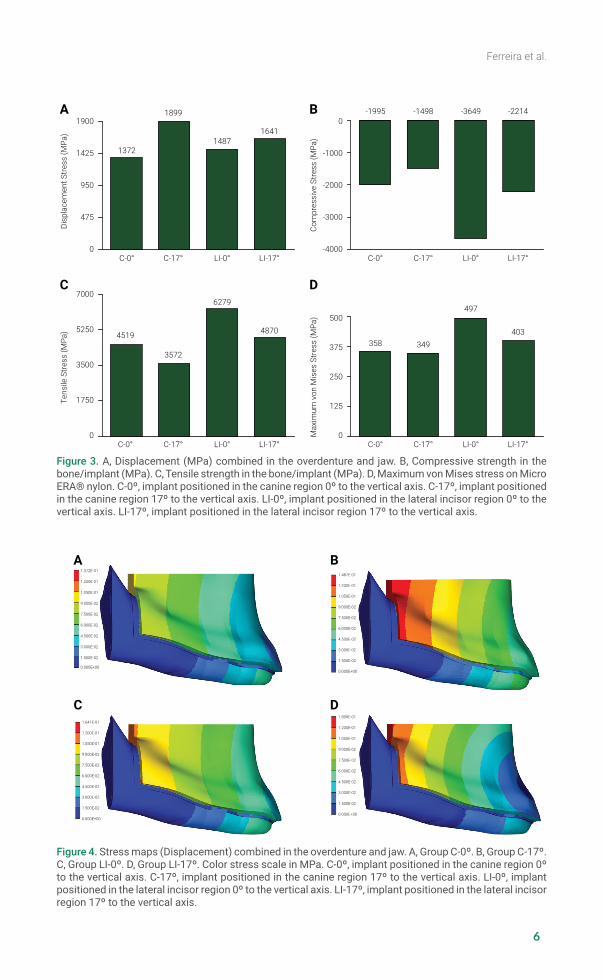
ResultsUnder the axial load on the mandibular premolar and molars, the highest displace-ment was observed for both angulated groups (C-17º and LI-17º) (Fig 3A). The C-17º group exhibited the highest displacement among all the other groups. When com-paring the compressive/tensile stress in the bone-implant interface the lateral-incisor groups (LI-0º and LI-17º) demonstrated the highest compressive stress (Fig 3B), while the canine groups (C-0º and C-17º) presented the lowest tensile stress (Fig 3C). The von Mises stress on the nylon component for the group LI-0º generated higher stress value among all groups (Fig 3D).
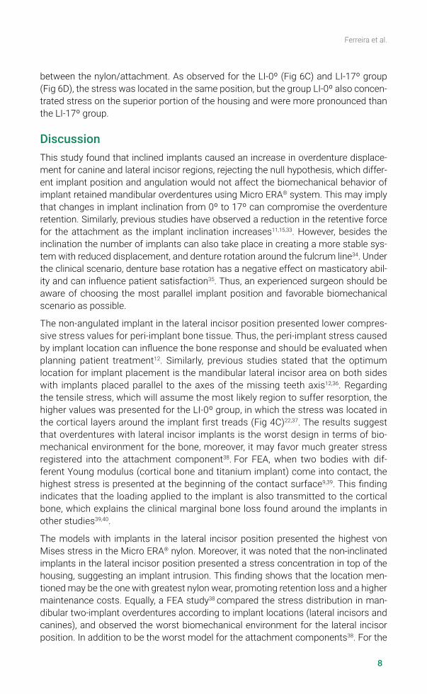
In Fig 4, the same pattern of stress maps was observed for all models, but with differ-ent intensity. The stress maps indicated the highest displacement stress for C-17º at the posterior region of the overdenture (Fig 4B).
Regarding the compressive/tensile stress in the bone/implant interface the groups with canine implants (C-0º and C-17º) presented the highest stress on the neck region, running through its first threads (Fig 5A and 5B). The group LI-0º (Fig 5C) presented stress located only in the distal region. The group LI-17º (Fig 5D) showed similar dis-tribution with C-0º and C-17º groups.
The Micro ERA® nylon component exhibited similar stress in the canine groups C-0º (Fig 6A) and C-17º (Fig 6B). The stresses were concentrated in the seating interface
Table 1. Mechanical properties of materials used for FEA analysis.
Material Young Modulus (Mpa) Poisson’s ratio (v) Reference
Cortical Bone 13 700 0,30 Liu, 201330
Cancellous Bone 1370 0,30 Liu, 201330
Mucosa 1 0,37 Liu, 201330
Titanium (Grade IV) 103 400 0,35 Barão, 200826
Nylon 2400 0,39 Barão, 200826
Stainless steel 190 000 0,31 Barão, 200826
Acrylic Resin 8300 0,28 Barão, 200826
6
Ferreira et al.Di
spla
cem
ent S
tress
(MPa
)
C-0° C-17° LI-0° LI-17°0
475
950
1425
1900
1372
1899
14871641
Com
pres
sive
Stre
ss (M
Pa)
C-0° C-17° LI-0° LI-17°-4000
-3000
-2000
-1000
0-1995 -1498 -3649 -2214
Tens
ile S
tress
(MPa
)
C-0° C-17° LI-0° LI-17°0
1750
3500
5250
7000
4519
3572
6279
4870
Max
imum
von
Mis
es S
tress
(MPa
)
C-0° C-17° LI-0° LI-17°0
125
250
375
500
358 349
497
403
A B
C D
Figure 3. A, Displacement (MPa) combined in the overdenture and jaw. B, Compressive strength in the bone/implant (MPa). C, Tensile strength in the bone/implant (MPa). D, Maximum von Mises stress on Micro ERA® nylon. C-0º, implant positioned in the canine region 0º to the vertical axis. C-17º, implant positioned in the canine region 17º to the vertical axis. LI-0º, implant positioned in the lateral incisor region 0º to the vertical axis. LI-17º, implant positioned in the lateral incisor region 17º to the vertical axis.
1.641E-01
1.200E-01
1.050E-01
9.000E-02
7.500E-02
6.000E-02
4.500E-02
3.000E-02
1.500E-02
0.000E+00
1.899E-01
1.200E-01
1.050E-01
9.000E-02
7.500E-02
6.000E-02
4.500E-02
3.000E-02
1.500E-02
0.000E+00
1.372E-01
1.200E-01
1.050E-01
9.000E-02
7.500E-02
6.000E-02
4.500E-02
3.000E-02
1.500E-02
0.000E+00
1.487E-01
1.200E-01
1.050E-01
9.000E-02
7.500E-02
6.000E-02
4.500E-02
3.000E-02
1.500E-02
0.000E+00
A B
C D
Figure 4. Stress maps (Displacement) combined in the overdenture and jaw. A, Group C-0º. B, Group C-17º. C, Group LI-0º. D, Group LI-17º. Color stress scale in MPa. C-0º, implant positioned in the canine region 0º to the vertical axis. C-17º, implant positioned in the canine region 17º to the vertical axis. LI-0º, implant positioned in the lateral incisor region 0º to the vertical axis. LI-17º, implant positioned in the lateral incisor region 17º to the vertical axis.

7
Ferreira et al.
4.519E+00
3.700E+00
2.643E+00
1.586E+00
5.286E+00
-5.286E+00
-1.586E+00
-2.643E+00
-3.700E-00
-4.757E+00
A B
C D
TensileStress Max
CompressiveStress Max
4.757E+00
3.700E+00
2.643E+00
1.586E+00
5.286E+00
-5.286E+00
-1.586E+00
-2.643E+00
-3.700E-00
-4.757E+00
TensileStress Max
CompressiveStress Max
6.279E+00
3.700E+00
2.643E+00
1.586E+00
5.286E+00
-5.286E+00
-1.586E+00
-2.643E+00
-3.700E-00
-4.757E+00
TensileStress Max
CompressiveStress Max
4.870E+00
3.700E+00
2.643E+00
1.586E+00
5.286E+00
-5.286E+00
-1.586E+00
-2.643E+00
-3.700E-00
-4.757E+00
TensileStress Max
CompressiveStress Max
Figure 5. Stress maps (compressive/tensile stress) on implant/bone interface. A, Group C-0º. B, Group C-17º. C, Group LI-0º. D, Group LI-17º. Color stress scale in MPa. C-0º, implant positioned in the canine region 0º to the vertical axis. C-17º, implant positioned in the canine region 17º to the vertical axis. LI-0º, implant positioned in the lateral incisor region 0º to the vertical axis. LI-17º, implant positioned in the lateral incisor region 17º to the vertical axis.
Figure 6. Stress maps (von Mises stress) on Micro ERA® nylon. A, Group C-0º. B, Group C-17º. C, Group LI-0º. D, Group LI-17º. Color stress scale in MPa. C-0º, implant positioned in the canine region 0º to the vertical axis. C-17º, implant positioned in the canine region 17º to the vertical axis. LI-0º, implant positioned in the lateral incisor region 0º to the vertical axis. LI-17º, implant positioned in the lateral incisor region 17º to the vertical axis.
3.580E+01
3.400E+01
2.916E+01
2.431E+01
1.947E+00
1.463E+00
9.786E+00
4.943E+00
1.000E-01
-4.743E+00
A B
C D
3.497E+01
3.400E+01
2.916E+01
2.431E+01
1.947E+00
1.463E+00
9.786E+00
4.943E+00
1.000E-01
-4.743E+00
4.570E+01
3.400E+01
2.916E+01
2.431E+01
1.947E+00
1.463E+00
9.786E+00
4.943E+00
1.000E-01
-2.171E+02
4.037E+01
3.400E+01
2.916E+01
2.431E+01
1.947E+00
1.463E+00
9.786E+00
4.943E+00
1.000E-01
-4.743E+00
8
Ferreira et al.
between the nylon/attachment. As observed for the LI-0º (Fig 6C) and LI-17º group (Fig 6D), the stress was located in the same position, but the group LI-0º also concen-trated stress on the superior portion of the housing and were more pronounced than the LI-17º group.
DiscussionThis study found that inclined implants caused an increase in overdenture displace-ment for canine and lateral incisor regions, rejecting the null hypothesis, which differ-ent implant position and angulation would not affect the biomechanical behavior of implant retained mandibular overdentures using Micro ERA® system. This may imply that changes in implant inclination from 0º to 17º can compromise the overdenture retention. Similarly, previous studies have observed a reduction in the retentive force for the attachment as the implant inclination increases11,15,33. However, besides the inclination the number of implants can also take place in creating a more stable sys-tem with reduced displacement, and denture rotation around the fulcrum line34. Under the clinical scenario, denture base rotation has a negative effect on masticatory abil-ity and can influence patient satisfaction35. Thus, an experienced surgeon should be aware of choosing the most parallel implant position and favorable biomechanical scenario as possible.
The non-angulated implant in the lateral incisor position presented lower compres-sive stress values for peri-implant bone tissue. Thus, the peri-implant stress caused by implant location can influence the bone response and should be evaluated when planning patient treatment12. Similarly, previous studies stated that the optimum location for implant placement is the mandibular lateral incisor area on both sides with implants placed parallel to the axes of the missing teeth axis12,36. Regarding the tensile stress, which will assume the most likely region to suffer resorption, the higher values was presented for the LI-0º group, in which the stress was located in the cortical layers around the implant first treads (Fig 4C)22,37. The results suggest that overdentures with lateral incisor implants is the worst design in terms of bio-mechanical environment for the bone, moreover, it may favor much greater stress registered into the attachment component38. For FEA, when two bodies with dif-ferent Young modulus (cortical bone and titanium implant) come into contact, the highest stress is presented at the beginning of the contact surface9,39. This finding indicates that the loading applied to the implant is also transmitted to the cortical bone, which explains the clinical marginal bone loss found around the implants in other studies39,40.
The models with implants in the lateral incisor position presented the highest von Mises stress in the Micro ERA® nylon. Moreover, it was noted that the non-inclinated implants in the lateral incisor position presented a stress concentration in top of the housing, suggesting an implant intrusion. This finding shows that the location men-tioned may be the one with greatest nylon wear, promoting retention loss and a higher maintenance costs. Equally, a FEA study38 compared the stress distribution in man-dibular two-implant overdentures according to implant locations (lateral incisors and canines), and observed the worst biomechanical environment for the lateral incisor position. In addition to be the worst model for the attachment components38. For the

9
Ferreira et al.
different angulations, a previous study found that implant/attachments perpendicular to the occlusal plane were appropriately retentive in the first year and the retentive capacity of the nylon component was affected by implant inclinations41. However, in this study the angulated implant groups presented the lowest stress compared to the parallel implants and, according to this, would take more time to lose retention. This can be explained by the angled attachment to compensate inclined implants, favoring biomechanically the system.
Finite element analysis is a useful method in dentistry to estimate the stress distribu-tion in the peri-implant bone, prostheses, and prosthetic components in different sce-narios. However, in a clinical situation it would not be possible to control bone density, soft tissue resilience, implant inclination and osseointegration12,22. Therefore, it has to be assumed simplifications related to material properties and geometry which some-times limit the data to be extrapolated into the clinical scenario26,30. In addition, the absence of bilateral loading is a limitation of this study, since the loading orientation can change the tension patterns. Despite the fact that mechanical load and stress dis-tribution are directly related to the implant longevity, further studies and clinical trials should be performed to better understand the difference implant location, validate the results of this FEA study and provide guidance for clinicians.
From this in silico study it can be concluded, despite the fact that mechanical load and stress distribution are directly related to the implant longevity, further studies and clinical trials should be performed. Also, it would allow a better understanding about the difference for implant location, validate the results of this FEA study and provide guidance for clinicians.
AcknowledgementsThe authors are grateful to Professor Pedro Yoshito Noritomi of the Renato Archer Information Technology Center (Brazil) for assistance in the models development, and Daniel Takanori Kemmoku for the computer-aided design files assistance.
REFERENCES
1. de Souza Batista VE, Vechiato-Filho AJ, Santiago JF Jr, Sonego MV, Verri FR, Dos Santos DM et al. Clinical viability of single implant-retained mandibular overdentures: a systematic review and meta-analysis. Int J Oral Maxillofac Surg. 2018 Sep;47(9):1166-1177. doi: 10.1016/j.ijom.2018.01.021.
2. Al-Zubeidi MI, Alsabeeha NH, Thomson WM, Payne AG. Patient satisfaction and dissatisfaction with Mandibular two-implant overdentures using different attachment systems: 5-Year Outcomes Clin Implant Dent Relat Res. 2012 Oct;14(5):696-707. doi: 10.1111/j.1708-8208.2010.00306.x.
3. Geckili O, Bilhan H, Bilgin T. Impact of mandibular two-implant retained overdentures on life quality in a group of elderly Turkish edentulous patients. Arch Gerontol Geriatr. 2011 Sep-Oct;53(2):233-6. doi: 10.1016/j.archger.2010.11.027.
4. Vercruyssen M, Marcelis K, Coucke W, Naert I, Quirynen M. Long-term, retrospective evaluation (implant and patient-centred outcome) of the two-implants-supported overdenture in the mandible. Part 1: survival rate. Clin Oral Implants Res. 2010 Apr 1;21(4):357-65. doi: 10.1111/j.1600-0501.2009.01849.x.

10
Ferreira et al.
5. Marcello-Machado RM, Faot F, Schuster AJ, Bielemann AM, Nascimento GG, Del Bel Cury AA. How fast can treatment with overdentures improve the masticatory function and OHRQoL of atrophic edentulous patients? A 1-year longitudinal clinical study. Clin Oral Implants Res. 2018 Feb;29(2):215-26. doi: 10.1111/clr.13101.
6. Harris D, Höfer S, O’Boyle CA, Sheridan S, Marley J, Benington IC, et al: A comparison of implant-retained mandibular overdentures and conventional dentures on quality of life in edentulous patients: a randomized, prospective, within-subject controlled clinical trial. Clin Oral Implants Res. 2013 Jan;24(1):96-103. doi: 10.1111/j.1600-0501.2011.02368.x.
7. Awad MA, Rashid F, Feine JS: Overdenture effectiveness study team consortium. The effect of mandibular 2-implant overdentures on oral health-related quality of life: an international multicentre study. Clin Oral Implants Res. 2014 Jan;25(1):46-51. doi: 10.1111/clr.12205.
8. Feine JS, Carlsson GE, Awad MA, Chehade A, Duncan WJ, Gizani S, et al: The McGill consensus statement on overdentures. Mandibular two-implant overdentures as first choice standard of care for edentulous patients. Int J Oral Maxillofac Implants 2002 Jul-Aug;17(4):6012.
9. Topkaya T, Solmaz MY. The effect of implant number and position on the stress behavior of mandibular implant retained overdentures: A three-dimensional finite element analysis. J Biomech. 2015 Jul 16;48(10):2102-9. doi: 10.1016/j.jbiomech.2015.03.006.
10. Schmitt A, Zarb GA. The notion of implant-supported overdentures. J Prosthet Dent. 1998 Jan;79(1):60-5.
11. Sultana N, Bartlett DW, Suleiman M. Retention of implant-supported overdentures at different implant angulations: comparing Locator and ball attachments. Clin Oral Implants Res. 2017 Nov;28(11):1406-10. doi: 10.1111/clr.13003.
12. Hong HR, Pae A, Kim Y, Paek J, Kim HS, Kwon KR. Effect of implant position, angulation, and attachment height on peri-implant bone stress associated with mandibular two-implant overdentures: a finite element analysis. Int J Oral Maxillofac Implants. 2012 Sep-Oct;27(5):e69-76.
13. Khadivi V. Correcting a nonparallel implant abutment for a mandibular overdenture retained by two implants: a clinical report. J Prosthet Dent 2004 Sep;92(3):216-9.
14. Lima Verde MA, Morgano SM, Hashem A. Technique to restore unfavorably inclined implants. J Prosthet Dent. 1994 Apr;71(4):359-63.
15. Yang TC, Maeda Y, Gonda T, Kotecha S. Attachment systems for implant overdenture: influence of implant inclination on retentive and lateral forces: retentive and lateral forces in implant inclination. Clin Oral Implants Res. 2011 Nov;22(11):1315-9. doi: 10.1111/j.1600-0501.2010.02137.x.
16. Walton JN, Huizinga SC, Peck CC. Implant angulation: a measurement technique, implant overdenture maintenance, and the influence of surgical experience. Int J Prosthodont. 2001 Nov-Dec;14(6):523-30.
17. Petropoulos VC, Smith W. Maximum dislodging forces of implant overdenture stud attachments. Int J Oral Maxillofac Implants 2002 Jul-Aug;17(4):526-35.
18. Chung KH, Chung CY, Cagna DR, Cronin RJ Jr. Retention characteristics of attachment systems for implant overdentures. J Prosthodont. 2004 Dec;13(4):221-6.
19. Cune M, Burgers M, van Kampen F, de Putter C, van der Bilt A. Mandibular overdentures retained by two implants: 10-year results from a crossover clinical trial comparing ball-socket and bar-clip attachments. Int J Prosthodont 2010 Jul-Aug;23(4):310-7.
20. van der Bilt A, van Kampen FMC, Cune MS. Masticatory function with mandibular implant-supported overdentures fitted with different attachment types. Eur J Oral Sci. 2006 Jun;114(3):191-6.
21. Presotto AGC, Bhering CLB, Mesquita MF, Barão VA. Marginal fit and photoelastic stress analysis of CAD-CAM and overcast 3-unit implant-supported frameworks. J Prosthet Dent. 2017 Mar;117(3):373-9. doi: 10.1016/j.prosdent.2016.06.011.

11
Ferreira et al.
22. Pisani MX, Presotto AGC, Mesquita MF, Barão VAR, Kemmoku DT, Del Bel Cury AA. Biomechanical behavior of 2-implant– and single-implant–retained mandibular overdentures with conventional or mini implants. J Prosthet Dent. 2018 Sep;120(3):421-30. doi: 10.1016/j.prosdent.2017.12.012.
23. Warin P, Rungsiyakull P, Rungsiyakull C, Khongkhunthian P. Effects of different numbers of mini-dental implants on alveolar ridge strain distribution under mandibular implant-retained overdentures. J Prosthodont Res. 2018 Jan;62(1):35-43. doi: 10.1016/j.jpor.2017.05.002.
24. Branemark PI, Zarb GA, Albrektsson T. Tissue-integrated prostheses: osseointegration in clinical dentistry. J Prosthet Dent. 1985 Oct;54(4):611-2.
25. Barão VAR, Assunção WG, Tabata LF, de Sousa EA, Rocha EP. Effect of different mucosa thickness and resiliency on stress distribution of implant-retained overdentures-2D FEA. Comput Methods Programs Biomed. 2008 Nov;92(2):213-23. doi: 10.1016/j.cmpb.2008.07.009.
26. Liu J, Pan S, Dong J, Mo Z, Fan Y, Feng H. Influence of implant number on the biomechanical behaviour of mandibular implant-retained/supported overdentures: a three-dimensional finite element analysis. J Dent. 2013 Mar;41(3):241-9. doi: 10.1016/j.jdent.2012.11.008.
27. Chen J, Ahmad R, Suenaga H, Li W, Swain M, Li Q. A comparative study on complete and implant retained denture treatments – A biomechanics perspective. J Biomech. 2015 Feb 5;48(3):512-9. doi: 10.1016/j.jbiomech.2014.11.043.
28. da Silva DP, Cazal C, de Almeida FC, Dias RB, Ballester RY. Photoelastic stress analysis surrounding implant-supported prosthesis and alveolar ridge on mandibular overdentures. Int J Dent. 2010;2010:780670. doi: 10.1155/2010/780670.
29. Chun HJ, Park DN, Han CH, Heo SJ, Heo MS, Koak JY. Stress distributions in maxillary bone surrounding overdenture implants with different overdenture attachments. J Oral Rehabil. 2005 Mar;32(3):193-205.
30. Barão VAR, Delben JA, Lima J, Cabral T, Assunção WG. Comparison of different designs of implant-retained overdentures and fixed full-arch implant-supported prosthesis on stress distribution in edentulous mandible – a computed tomography-based three-dimensional finite element analysis. J Biomech. 2013 Apr 26;46(7):1312-20. doi: 10.1016/j.jbiomech.2013.02.008.
31. El-Anwar MI, El-Taftazany EA, Hamed HA, ElHay MAA. Influence of number of implants and attachment type on stress distribution in mandibular implant-retained overdentures: finite element analysis. Open Access Maced J Med Sci. 2017 Mar 22;5(2):244-9. doi: 10.3889/oamjms.2017.047.
32. Kasani R, Rama Sai Attili BK, Dommeti VK, Merdji A, Biswas JK, Roy S. Stress distribution of overdenture using odd number implants – A Finite Element Study. J Mech Behav Biomed Mater. 2019 Oct;98:369-82. doi: 10.1016/j.jmbbm.2019.06.030.
33. Gulizio MP, Agar JR, Kelly JR, Taylor TD. effect of implant angulation upon retention of overdenture attachments. J Prosthodont 2005 Mar;14(1):3-11.
34. Oda K, Kanazawa M, Takeshita S, Minakuchi S. Influence of implant number on the movement of mandibular implant overdentures. J Prosthet Dent. 2017 Mar;117(3):380-5. doi: 10.1016/j.prosdent.2016.08.005.
35. Kimoto S, Pan S, Drolet N, Feine JS. Rotational movements of mandibular two-implant overdentures. Clin Oral Implants Res. 2009 Aug;20(8):838-43. doi: 10.1111/j.1600-0501.2009.01723.x.
36. Vogel RC. Implant overdentures: a new standard of care for edentulous patients current concepts and techniques. Compend Contin Educ Dent. 2008 Jun;29(5):270-6; quiz 277-8.
37. Borges Radaelli MT, Idogava HT, Spazzin AO, Noritomi PY, Boscato N. Parafunctional loading and occlusal device on stress distribution around implants: A 3D finite element analysis. J Prosthet Dent. 2018 Oct;120(4):565-72. doi: 10.1016/j.prosdent.2017.12.023.

12
Ferreira et al.
38. Alvarez-Arenal A, Gonzalez-Gonzalez I, deLlanos- Lanchares H, Martin-Fernandez E, Brizuela-Velasco A, Ellacuria-Echebarria. Effect of implant- and occlusal load location on stress distribution in Locator attachments of mandibular overdenture. A finite element study. J Adv Prosthodont. 2017 Oct;9(5):371-80. doi: 10.4047/jap.2017.9.5.371.
39. Kurniawan D, Nor FM, Lee HY, Lim JY. Finite element analysis of bone–implant biomechanics: refinement through featuring various osseointegration conditions. Int J Oral Maxillofac Surg. 2012 Sep;41(9):1090-6. doi: 10.1016/j.ijom.2011.12.026.
40. Arat Bilhan S, Baykasoglu C, Bilhan H, Kutay O, Mugan A. Effect of attachment types and number of implants supporting mandibular overdentures on stress distribution: a computed tomography-based 3D finite element analysis. J Biomech. 2015 Jan 2;48(1):130-7. doi: 10.1016/j.jbiomech.2014.10.022.
41. Rodrigues RC, Faria AC, Macedo AP, Sartori IA, de Mattos Mda G, Ribeiro RF. An in vitro study of non-axial forces upon the retention of an O-ring attachment. Clin Oral Implants Res. 2009 Dec;20(12):1314-9. doi: 10.1111/j.1600-0501.2009.01742.x.