volume 9, issue 11, may 2020 design analysis and
TRANSCRIPT
ISSN: 2277-3754
ISO 9001:2008 Certified International Journal of Engineering and Innovative Technology (IJEIT)
Volume 9, Issue 11, May 2020
DOI:10.17605/OSF.IO/ZFKVB Page 16
Abstract— Various components used in mechanical industry
especially automobile and aircraft industry are manufactured by
sheet metal. Press tools are used to produce particular sheet metal
components in large amount. Accuracy of components depends
up on press tool construction and configuration. Main
characteristic of press working operations are high rate of
production associated with low unit cost production. Aim of the
project is to conceptual design through geometrical modeling in
2D sketch and three dimensional modeling make easy
understanding of press tool construction. Cad model prepared
using Auto CAD and Auto Desk Inventor. Structural analysis
carried out to analyze deformation and stress distribution. Quality
control tool cause and effect diagram which is used to analyze
various parameter which effect wrinkling.
Index Terms—Press Tool, Cad, Auto Desk Inventor,
Wrinkling, Geometrical modeling, and conceptual design.
I. INTRODUCTION
Mass production always pointing towards increasing
quality and productivity. Press working also called stamping
or sheet stamping is a cold working process happening in
below recrystallization temperature. Press working operations
are important operation of converting raw material in to a
finished product. Press tool are mechanical devices used for
producing sheet metal component in large volume Press
working processes are carried out on working material in the
form of sheet. Metal having thickness less than 6mm is called
strip. Metal having thickness greater than 6mm is called plate
This work focus on designing two separate open tools used
for cylindrical cup formation. Step by step designing
procedure for blanking and drawing tool are deeply followed.
Various solid modeling packages are available in order is
to easy model the press tool. Auto Desk inventor is a basic
level software package available. 2D and 3D design of tools
make easy understand for various functions of each
components of a fixture. Two dimensional and three
dimensional modeling of the components, analyzing stress
and displacement on the components. Modeling and structural
analysis of the components was carried out on Auto Desk
inventor.
Predominant failure modes in sheet metal parts in drawing
process are wrinkling. The prediction and prevention of
wrinkling is extremely important in the design of tooling and
process parameter in drawing process.
Cause and effect diagram one of seven quality tool is used
to analyze various parameter which effect wrinkling defect.
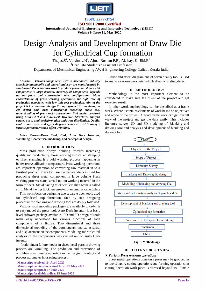
II. METHODOLOGY
Methodology is the most important element to be
considered to make sure the fluent of the project and get
expected result.
In other words methodology can be described as a frame
work. Where it contains elements of work based on objectives
and scope of the project. A good frame work can get overall
view of the project and get the data easily. This includes
literature survey 2D and 3D modeling of Blanking and
drawing tool and analysis and development of blanking and
drawing tool.
Fig: 1 Methodology
III. LITERATURE REVIEW
Various Press working operations
Sheet metal operations done on a press may be grouped in
to two category cutting operations and forming operations .in
cutting operation work piece is stressed beyond its ultimate
Design Analysis and Development of Draw Die
for Cylindrical Cup formation Thejas.S
1, Vaishnav.N
1, Ajmal Roshan P.P
1, Akshay. K
1 Jibi.R
2
1Graduate Students
2Assistant Professor
Department of Mechanical Engineering AWH Engineering College Calicut Kerala India
Manuscript received: 24 April 2020
Manuscript received in revised form: 22 May 2020
Manuscript accepted: 07 June 2020
Manuscript Available online: 15 June 2020

ISSN: 2277-3754
ISO 9001:2008 Certified International Journal of Engineering and Innovative Technology (IJEIT)
Volume 9, Issue 11, May 2020
DOI:10.17605/OSF.IO/ZFKVB Page 17
strength. In forming operation stress below ultimate strength.
Various cutting operations are
Piercing: operation to make hole or cut out opening of
regular or irregular shapes in the blank /stamping. The
punched out piece is slug.
Blanking: Process of producing flat stamping. The entire
periphery is cut out and the cut out piece is called blank.
Blanking is cutting a whole piece from sheet metal along a
closed contour.
Notching: The process of removing a small area of metal
from one or both edge of the strip.
Parting; An operation that separate the stock material
along a straight line in a double cut line.
Cutt-off: An operation to separate the component from the
stock material along a straight line in single cut line.
Lancing: Combination of cutting and forming operation. In
this operation no material is cut off from the stock material.
Trimming: Secondary operation to remove distorted and
excess metal from draw components.
Shaving: Small amount of material is removed from edge
of a blank or pierced hole. Considered as secondary
operation.
Perforating: Process of piercing a series of hole of
different shapes in a blank.
Various non cutting operations are
Bending: In this operation shape the material around a
straight axis which extends completely across the material.
Forming: In this operation shape the material around a
curved axis instead of straight axis.
Drawing: In this operation flat blank is transferred in to
cylindrical cup.
Curling: Rolling the edge of the component in to roll or a
curl. The purpose being to strengthen the edge and to produce
a protective edge.
Press tool
Press tools are tools manufactured to produce a particular
component either punched or formed with high degree of
precision out of sheet metal. In this type of tooling no chip
formation.
Types of Dies
According to operation: Cutting or shearing die and
forming or non cutting die.
According to method of operation
a) A simple dies to perform only one operation.
b) Multi operation die -these dies are designed to perform
more than one operation in one stroke of ram. These are
further classified as below.
I. Compound Die
II. Combination Die
III. Progressive Die
IV. Transfer Die
1. Compound Dies
It is the die in which two or more than two operations may
be completed at one station (cutting operation).This die is
considered as cutting dies in which different operations like
Piercing & blanking will take place at one station.
2. Combination Die
It is combination die in which more than two operations
may be completed at one station i.e. cutting operations and
forming.
3. Progressive Die
Progressive die has series of station at each station one
operation on work piece within one stroke of press machine &
each time metal strip is transfer to next station.
4. Transfer Die
Unlike progressive die the metal strip is feed progressively
from one station to another. In transfer die the already cut
blanks are feed mechanically from one station to next station.
Press tool terminology
The figure below shows press tool terminology
Fig: 2 Press Tool Terminologies
Shank: It is an element of press tool which act as a
connecting link between the press tool and press. The
diameter of the shank should fit in to the bore in the press tool
ram.
Top plate: This is the plate on which the top half /moving
half of the press tool is fixed. Shank is also fixed on top plate
which connects the tool to the press.
Thrust plate/black plate: This is case hardened steel plate
mounted below the top plate to avoid digging in off the
hardened punch in to top plate.
Punch holder: It is mild steel plate which holds the punch.
The punch is fitted to the punch holder with a light press fit.
Punch and Die: These are cutting element of the tool.
They are usually made of high carbon high chromium steel,
and are hardened and tempered.
Stripper: The main function of the stripper is guide the
punch in to die and also strip the stock material of the punch.
Piolet: The function of piolet is to position the stock
material accurately and bring the material in to proper
position for succeeding operations.
Stopper: These are used for correct spacing of sheet metal
for corresponding press operation over the die plate.
Guide pillar and bush: These are used to achieve a well
guided movement of moving half of the tool to the fixed half
of press tool. In top plate bush are fitted and in between guide
pillar and bush have a sliding fit.

ISSN: 2277-3754
ISO 9001:2008 Certified International Journal of Engineering and Innovative Technology (IJEIT)
Volume 9, Issue 11, May 2020
DOI:10.17605/OSF.IO/ZFKVB Page 18
Bottom plate: this is the base of press tool.it is made in
mild steel.the die at the pillar are fiited in the plate.this plate is
fastened to the press bed.
Shunt height: It is the distance from top of the bed to the
bottom of the slide with its stroke down and adjustment up.
Theory of shearing
The name shearing stands for method of cutting sheets
stock without forming chips. In blanking /piercing tool as the
punch contact the stock material which over the die plate a
pressure build up occur due to this excessive load when the
elastic limit exceeded the material flow plastically and punch
penetrate the stock material continuously blank or slug in to
the die opening. Further continuation of punching pressure
causes the start of fracture at the cutting edge of punch and
dies and on continuation the fracture meets and the stock is
sheared/cut. Shearing action consist three stages
First stage: plastic deformation: The pressure applied by
the punch on the stock material tends to deform it in to the die
opening. The strip is over the die plate and punch contacts the
stock material and exerts pressure up on the strip as the press
ram is forced down, as the elastic limit of the stock material is
exceeded plastic deformation take place. Due to this a radius
is formed on the top edge of the strip and the bottom edge of
slug/blank .this radius is referred as roll over.
Second stage:Penetration:As driving force of the ram
continues the punch is forced to penetrate the stock material
and the blank or slug is forcefully displaced in to die opening
a considerable amount compression of the slug material
against the wall of the die opening produces a highly shining
portion on the edge of the blank/slug.At the same time the
plastic flow pull the material around the punch causing a
corresponding shining portion on the edge of the work stock
material .This is referred to as cut band. Which is
approximately one third of thickness of stock material.
Fig: 3 Stages in Shearing
Third stage: Fracture: Further continuation of punching
pressure then material near the cutting edge of the punch and
die become highly stressed. When the stress goes beyond the
ultimate strength of material fracture start to arise at the
cutting edge of the punch and die. Under proper cutting
condition the fracture extend toward each other and meet.
When this occurs the fracture complete and blank /slug is
separated from the stock material. Slight burr will be formed
along the top edge of the slug and the bottom edge of stock
material. Then punch enters the die opening slightly pushing
the slug/blank slightly below cutting edge.
IV. IMPLEMENTATION
Component Drawing
Fig: 4. 2 D and 3D Sketch
Aluminum: Properties
Aluminum Alloy 6063
Shear strength: 207Mpa
Young's Modulus: 69.5Gpa
Yield Strength: 240Mpa
Density: 2.70g/cm3
Melting Point: 600 C
Modulus of rigidity: 69.5Gpa
Chemical Composition
Table 1: Chemical Composition
Blanking Die Design
1. Blank size determination
2. Design of strip layout
3. Calculation of economic factor
4. Calculation of Cutting Force and Calculation of
stripping
5. Calculation of cutting clearance
6. Determination of punch and die size
7. Calculation of plate thickness Die plate, stripper
plate, punch holder, thrust plate
8. Checking punch for crushing
9. Calculation of critical buckling load and critical

ISSN: 2277-3754
ISO 9001:2008 Certified International Journal of Engineering and Innovative Technology (IJEIT)
Volume 9, Issue 11, May 2020
DOI:10.17605/OSF.IO/ZFKVB Page 19
length of punch
10. Calculation of deflection of punch
11. Calculation of deflection of die plate
1. Blank Size Determination
Calculation of d/r Ratio
d=30mm r=3mm
=30/3=10
d/r ratio between 10 and 15
Blank size D=√ d2+4dh-r
=√ (30)2+ (4x20x30)-3
=57.41mm
0.15 mm is added as trim allowance
Blank diameter=57.41+0.15=57.56=58mm
2 & 3. Design of Strip layout and Calculation of
Economic factor
Economic factor not less than 70%
Fig 5: Strip Layout
Scrap bridge = T to 1.2 T
= 1.2 x1.5=1.8mm=2mm
Margin =1.25 to 1.5T
=1.5x1.5=2.25mm
Economic Factor= (Area of blank x100xNo of
rows)/(pitch x width of strip)
Area of blank=πD2/4
= 3.14x (58) 2/4
= 2640.74mm2
Economic factor= (2640.74x100x1)/(60.5x62)=70.4%
4. Calculation of Cutting Force
Cutting force =LxSxTmax
L=Length of periphery to be cut in mm
S=Stock thickness in mm
Tmax=shear strength of material N/mm2
Length of periphery to be cut= πD=3.14x58=182.12mm
Tmax=207Mpa
Stock thickness=1.5mm
Cutting force= LxSxTmax
=1.5x182.12X207
= 56548.26N
Stripping Force=20%cutting force
= 56548.26x.20=11309.65N
5. Calculation of Cutting Clearance
Cutting clearance
C=0.0032t√ts mm/side
t=sheet thickness=1.5mm
ts=207Mpa
C=0.0032x1.5x√207=0.069mm per side
6. Determination of Punch and Die Size
Blanking Die size=Blank size=58mm
Blanking Punch size= (Blank size-Total clearance)
=58-(2X0.0690)
= 57.862mm
7. Calculation of Plate thickness Die plate, stripper plate,
punch holder, thrust plate
Die plate thickness = (cutting force) 1/3
= (56548.26) 1/3
=38.38=40mm
Punch holder plate thickness=0.75xthickness of die plate
=0.75x40=30mm
Thrust plate thickness =15 to20mm=15mm
Stripper plate thickness =0.5xdie plate
thickness=40x0.5=20mm
8. Checking Punch for Crushing
Cutting force = π/4 xd2x σc
56548.26 = π/4 x(57.862) 2x σc
56548.26 =2628.18x σc
σc = 21.51N/mm2
σc =21.51N/mm2<<<250N/mm
2 Safe in crushing
Slendness Ratio
Compressive strength= 250N/mm2
250 = (π2E)/ (l/k)
2
(l/k) 2= (3.14
2x200x10
3)/250
(l/K)=88.81
Slendness ratio greater than 80 Eulers formula for a mild
steel column is vali

ISSN: 2277-3754
ISO 9001:2008 Certified International Journal of Engineering and Innovative Technology (IJEIT)
Volume 9, Issue 11, May 2020
DOI:10.17605/OSF.IO/ZFKVB Page 20
9. Calculation of Critical Buckling Load and Critical
Length of Punch
Critical buckling force and critical length of punch
Pcr = (π2EI)/ (4L
2)
I=Moment of inertia= (π /64) xd4
I= (π /64) x (58) 4
I=555215.58mm4
L=Longitudinal length of punch=50mm
Pcr = (3.14) 2x200x10
3x555215.58
4x (50) 2
=109484070.65N
Critical buckling load>>>Cutting force. Punch is safe from
buckling
Maximum length that can be used if applied load equal to
critical load with safety factor 4.
Lcr=√ (π2EImin)/4CP
= π2x200x
10
3 x555215.58
= √ 4x (4x56548.26)
=1100mm
Punch is safe from buckling because the punch length lower
than 1100mm. Unguided length of punch is 50mm with
overall length of 80mm.
10. Calculation of Deflection of Punch
Deflection of blanking punch.
=FbL3/3EI
= (56548.26x503)/ (3x200x10
3x555215.58)
=0.02120mm
11. Calculation of Deflection of Die Plate
Compressive stress in blanking die
Mean compressive stress =Vertical force
Shearing area Shearing Area= π/4 x (58)2=2640.74mm
2
=56548.26/2640.74 =21.41Mpa
Deflection of Die
Deflection of blanking die
=FL3/192EI
F =80% cutting force
F = 0.8x56548.26
=45238.60N
L=100mm
I=bh3/12=100x (40)3/12=533333.3mm4.
=45238.60x (100)3)/(192x200x103x533333.3)
=.0022089mm
Modeling of Blanking Tool
Fig 6: Modeling of Blanking Tool
Fig 7: Exploded View Blanking Tool
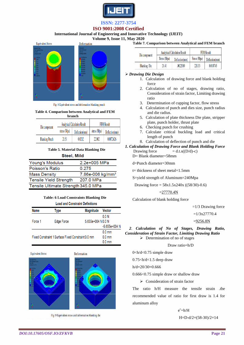
FEM Analysis of Blanking Punch and Blanking Die
Analysis of Blanking Punch
Table: 2 Material data Blanking Punch
Table: 3 Load Constraints Blanking Punch
ISSN: 2277-3754
ISO 9001:2008 Certified International Journal of Engineering and Innovative Technology (IJEIT)
Volume 9, Issue 11, May 2020
DOI:10.17605/OSF.IO/ZFKVB Page 21
Table 4. Comparison between Analytical and FEM
branch
Table 5. Material Data Blanking Die
Table: 6 Load Constraints Blanking Die
Table 7. Comparison between Analytical and FEM branch
Drawing Die Design
1. Calculation of drawing force and blank holding
force
2. Calculation of no of stages, drawing ratio,
Consideration of strain factor, Limiting drawing
ratio
3. Determination of cupping factor, flow stress
4. Calculation of punch and dies size, punch radius
and die radius.
5. Calculation of plate thickness Die plate, stripper
plate, punch holder, thrust plate
6. Checking punch for crushing
7. Calculate critical buckling load and critical
length of punch
8. Calculation of deflection of punch and die
1. Calculation of Drawing Force and Blank Holding Force
Drawing force = d.t.s((D/d)-c)
D= Blank diameter=58mm
d=Punch diameter=30mm
t= thickness of sheet metal=1.5mm
S=yield strength of Aluminum=240Mpa
Drawing force = 58x1.5x240x ((58/30)-0.6)
=27770.4N
Calculation of blank holding force
=1/3 Drawing force
=1/3x27770.4
=9256.8N
2. Calculation of No of Stages, Drawing Ratio,
Consideration of Strain Factor, Limiting Drawing Ratio
Determination of no of stages
Draw ratio=h/D
0<h/d<0.75 simple draw
0.75<h/d<1.5 deep draw
h/d=20/30=0.666
0.666<0.75 simple draw or shallow draw
Consideration of strain factor
The ratio h/H measure the tensile strain .the
recommended value of ratio for first draw is 1.4 for
aluminum alloy
ec=h/H
H=D-d/2=(58-30)/2=14

ISSN: 2277-3754
ISO 9001:2008 Certified International Journal of Engineering and Innovative Technology (IJEIT)
Volume 9, Issue 11, May 2020
DOI:10.17605/OSF.IO/ZFKVB Page 22
h=D2-d
2/4D= ((58)
2-(30)
2)/ (4X30) =20.53
h/H=20.53/14=1.46
Consideration of d/D ratio
Recommended value of d/D value for first draw for
aluminum 0.52
d/D=30/58=0.51
Limiting drawing ratio
Limiting drawing ratio is defined as the maximum ratio
of blank sheet diameter to punch dia.
LDR=Dbmax/Dp
=58/30=1.9
An approximate upper limit on the drawing ratio is a
value of 2
Draw reduction
For one draw the percentage reduction permissible is
about 50%
%reduction=((D-d)/D)x100=((58-30)/58)x100=48.27%
So it is obivious that cup can draw in one draw.
3. Determination of Cupping Factor, Flow Stress
Calculation of cupping factor
Cupping strain factor € gives the actual strain in the metal
created by its elongation during drawing process
€ = ((D/d) +1)/2
€ = ((58/30) +1)/2
=1.43
Flow stress
σt = KƐn
K=Modulus of rigidity=69.5Mpa
n=strain hardening coefficient=0.095
Ɛ=strain=1/2ln (D/d) =0.5xln (58/30) =0.067
σt = 69.5x0.0670.095
=53.76Mpa
4. Calculation of Punch and Dies Size, Punch Radius and
Die Radius
Punch diameter=30mm
Punch radius=3mm
Die diameter=dp+2x (1.1t) =30+2x (1.1x1.5)=33mm
Draw radius= 4to 10 times blank thickness=6x1.5=9mm
5. Calculation of Plate Thickness Die Plate, Stripper Plate,
Punch Holder, Thrust Plate
Die plate thickness= (Drawing force) 1/3
= (27770.4)1/3
=30mm
Stripper plate=0.5xDie plate thickness=0.5x30=15mm
Punch holder plate=0.75xDie plate
thickness=0.75x30=22.5mm
Thrust plate thickness=15mm
6. Checking Punch for Crushing
Checking for punch crushing
Drawing force= π/4 xd2x σc
27770.4 = π/4 x (30)2x σc
σc =39.30N/mm2
σc =39.30N/mm2
<<< 250
N/mm2
Safe in crushing
Slendness ratio
Compressive strength= 250N/mm2
250 = (π2E)/(l/k)
2
(l/k) 2= (3.14
2x200x10
3)/250
(l/K)=88.81
Slendness ratio greater than 80 Eulers formula for a mild
steel column is valid
7. Calculate Critical Buckling Load and Critical Length of
Punch
Critical buckling force
Pcr = (π2EI)/ (4L
2)
I=Moment of inertia=( π /64)xd4
I= (π /64) x (30) 4
I=39740.62mm4
L=Longitudinal length of punch=60mm
Pcr = (3.14) 2x200x10
3x39740.62
4x (50) 2
=5442036.347N
Critical buckling load>>>drawing force. Punch is safe
from buckling
critical length of punch
Maximum length that can be used if applied load equal to
critical load with safety factor 4.
Lcr=√ (π2EImin)/4CP
= π2x200x
10
3 x39740.62
√ 4x (4x27770.4)
ISSN: 2277-3754
ISO 9001:2008 Certified International Journal of Engineering and Innovative Technology (IJEIT)
Volume 9, Issue 11, May 2020
DOI:10.17605/OSF.IO/ZFKVB Page 23
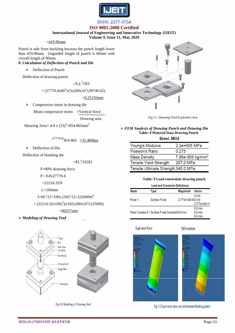
=419.96mm
Punch is safe from buckling because the punch length lower
than 419.96mm. Unguided length of punch is 60mm with
overall length of 80mm.
8. Calculation of Deflection of Punch and Die
Deflection of Punch
Deflection of drawing punch.
=FbL3/3EI
= (27770.4x603)/(3x200x10
3x39740.62)
=0.25156mm
Compressive stress in drawing die
Mean compressive stress =Vertical force
Drawing area
Shearing Area= π/4 x (33)
2=854.865mm
2
=27770.4/854.865 =32.48Mpa
Deflection of Die
Deflection of blanking die
=FL3/192EI
F=80% drawing force
F= 0.8x27770.4
=22216.32N
L=100mm
I=bh3/12=100x (30)
3/12=225000m
4.
= (22216.32x100)3)/(192x200x10
3x225000)
=00257mm
Modeling of Drawing Tool
FEM Analysis of Drawing Punch and Drawing Die Table: 8 Material Data Drawing Punch
Table: 9 Load constraints drawing punch

ISSN: 2277-3754
ISO 9001:2008 Certified International Journal of Engineering and Innovative Technology (IJEIT)
Volume 9, Issue 11, May 2020
DOI:10.17605/OSF.IO/ZFKVB Page 24
Table 10. Comparison between Analytical and FEM
branch
Table 11.Material data Drawing Die
Table: 12 Load constraints Drawing Die
Table 13. Comparison between Analytical and FEM
branch
Development of Blanking Tool and Drawing Tool
Fig 14: Blanking Tool and Drawing Tool
Component
Fig 15: Strip Blank and Cylindrical Cup
Cause and Effect Diagram for Wrinkling
Fig 16. Cause and Effect diagram for wrinkling
V.CONCLUSION
In this work some significant aspects of press tool design
for cylindrical cup is discussed and also detailed study and
analysis were carried out. By implementing computer in
design accuracy of design is improved and design process
time is reduced drastically than by traditional method. Punch
and die analysis of the tool were carried out and the design
found to be safe. Results obtained through analysis are
approximately nearer to the theoretical value. Cause effect
diagram is used to clearly understand parameter which
effecting wrinkling defect.
VI.FUTURE WORK
CAE plays very significant role in the decision making of
various parameter of sheet metal forming processes and it
helps to designer during product design as well as tool design
stage to decide optimum and accurate process parameter.CAE
software such as Hyper form, FEA used for formability
analysis and prediction of wrinkles. The effect of various

ISSN: 2277-3754
ISO 9001:2008 Certified International Journal of Engineering and Innovative Technology (IJEIT)
Volume 9, Issue 11, May 2020
DOI:10.17605/OSF.IO/ZFKVB Page 25
parameter that cause wrinkling defect can be determined
using statically as well as experimental method.
REFERENCES [1] B hagyashri Billade Prof. Sachine Dahake. ”Design and
analysis of Draw bead profile in sheet metal forming of rein
–rfend upr-lh/rh for safe thinning” IJESI Volume 7 Issue 7.
[2] Fissa Biruke Teshome Yonas Mitiku Degu. ”Design of
combined press tool for the manufacturing of rise thresher
blade”THE IJES Volume 3 Issue 4 2014.
[3] Vyshakh Sannamani L G Dr Ramegowda D. ”Design analysis
of punch and die for blanking piercing and forming tools to
produce chain guide mounting bottom bracket”IJIMINDS
Volume 3 Issue 8 2016 .
[4] Abhijit Ajabrao Tagade Nilesh Nirwan”Design and
manufacturing of compound press tool for washer”IJSR
Volume 5 Issue 8 August 2016.
[5] Gaurav C Rathod Dr D Raut. Study and analysis of press tool
design” ijert Volume 6 Issue 7 2017.
AUTHOR BIOGRAPHY
Mr. Jibi. R Received M-tech in Production and
Industrial Engineering from SCMS School of
Engineering and Technology Ernakulum Kerala in
2013.Recieved B-tech Degree in Mechanical
Engineering from CUIET Malappuram Kerala in
2011 and Diploma in Tool and Die Making from
KELTRAC Alappuzha in 2008.He has published
Seven International journals and presented two articles in International
conference. He has more than seven years experience in teaching and one
year Industrial experience in Press tool and Mold making. His interested area
is computer aided design and analysis, Production Technology and
Industrial Hydraulics. Currently he is working as an Assistant Professor in
the mechanical engineering department at AWH Engineering College
Calicut Kerala India.
Mr. Thejas.S Final year B-tech student in the mechanical
Engineering Department at AWH Engineering College Calicut
Kerala India
Mr. Vaishnav.N Final year B-tech student in the mechanical
Engineering Department at AWH Engineering College Calicut
Kerala India
Mr. Ajmal Roshan P.P Final year B-tech student in the
mechanical Engineering Department at AWH Engineering
College Calicut Kerala India
Mr. Akshay. K Final year B-tech student in the mechanical
Engineering Department at AWH Engineering College Calicut
Kerala India