volume v – part 7 steel plate girder standards · holders of volume v – part 7: steel plate...
TRANSCRIPT

VOLUME V – PART 7
STEEL PLATE GIRDER STANDARDS
VIRGINIA DEPARTMENT OF
TRANSPORTATION
VirginiaDOT.org WE KEEP VIRGINIA MOVING
COMMONWEALTH of VIRGINIA
DEPARTMENT OF TRANSPORTATION 1401 EAST BROAD STREET
RICHMOND, 23219-2000
Gregory A. Whirley COMMISSIONER
August 30, 2012 SUBJECT: Manual of the Structure and Bridge Division Volume V – Part 7 Steel Plate Girder Standards MEMORANDUM TO: Holders of Volume V – Part 7: Steel Plate Girder Standards The revision is intended to clarify modifications to standards. Design waivers/exceptions are required when changes to the standards are made. VOIDED: None NEW ISSUES:
None REVISIONS: File Number Description of change(s) TOC-1 Revised date of sheet. INSTR-1 Added instructions for completing the sheet; revised modification
policy.

Page 2 August 30, 2012 RETAIN THIS MEMO IN FRONT OF INDEX TO VOLUME V – PART 7 /original signed/ Julius F. J. Völgyi, Jr., P.E. Assistant State Structure and Bridge Engineer For: Kendal R. Walus, P.E. State Structure and Bridge Engineer

VirginiaDOT.org WE KEEP VIRGINIA MOVING
COMMONWEALTH of VIRGINIA
DEPARTMENT OF TRANSPORTATION 1401 EAST BROAD STREET
RICHMOND, 23219-2000
Gregory A. Whirley Acting COMMISSIONER
June 14, 2010 SUBJECT: Manual of the Structure and Bridge Division Volume V – Part 7 Steel Plate Girder Standards MEMORANDUM TO: Holders of Volume V – Part 7: Steel Plate Girder Standards VOIDED: None NEW ISSUES: File Number Description of change(s) None REVISIONS: Note: For all standards, the block with FHWA Region 3 and block in the upper right corner for Special Provisions/Copied Notes has been deleted. The copyright date has been changed to 2010.
Page 2 June 14,2010 RETAIN THIS MEMO IN FRONT OF INDEX TO VOLUME V – PART 7 /original signed/ Julius F. J. Völgyi, Jr., P.E. Assistant State Structure and Bridge Engineer For: Kendal R. Walus, P.E. State Structure and Bridge Engineer
VirginiaDOT.org WE KEEP VIRGINIA MOVING
COMMONWEALTH of VIRGINIA
DEPARTMENT OF TRANSPORTATION 1401 EAST BROAD STREET
RICHMOND, 23219-2000 David S. Ekern, P.E.
COMMISSIONER
May 29, 2009 SUBJECT: Manual of the Structure and Bridge Division Volume V – Part 7 Steel Plate Girder Standards MEMORANDUM TO: Holders of Volume V – Part 7: Steel Plate Girder Standards NOTE: Effective with the December Advertisement, Standards shall be sealed and signed in accordance with Volume V – Part 2, File No. 01.16.1 thru 01.16.7. VOIDED STANDARDS: None NEW ISSUES: None REVISIONS: File Number Description of changes(s) All standard sheets SGDET1B-1 SGDET1B-2 SGDET1BC-1 SGDET1BC-2
All standard sheets have been revised to reflect the border forsealing and signing of plans. Minor drafting correction. NOTES TO DESIGNER: Added 1/8” increment on values. Minor drafting correction. NOTES TO DESIGNER: Added 1/8” increment on values.
Page 2 May 29, 2009 REVISIONS: File Number Description of changes(s) SGCAM2-2 SGDLD2-2 SGCAM2C-2 SGDLD2C-2 SGCAM3-2 SGDLD3-2 SGCAM3C-2 SGDLD3C-2 SGCAM4-2 SGDLD4A-2 SGCAM4AC-2 SGDLD4AC-2
NOTES TO DESIGNER: Added 1/8” increment on values. NOTES TO DESIGNER: Added 1/8” increment on values. NOTES TO DESIGNER: Added 1/8” increment on values. NOTES TO DESIGNER: Added 1/8” increment on values. NOTES TO DESIGNER: Added 1/8” increment on values. NOTES TO DESIGNER: Added 1/8” increment on values. NOTES TO DESIGNER: Added 1/8” increment on values. NOTES TO DESIGNER: Added 1/8” increment on values. NOTES TO DESIGNER: Added 1/8” increment on values. NOTES TO DESIGNER: Added 1/8” increment on values. NOTES TO DESIGNER: Added 1/8” increment on values. NOTES TO DESIGNER: Added 1/8” increment on values.
RETAIN THIS MEMO IN FRONT OF INDEX TO VOLUME V – PART 7 /original signed/ Julius F. J. Völgyi, Jr., P.E. Assistant State Structure and Bridge Engineer For: Kendal R. Walus, P.E. State Structure and Bridge Engineer

VirginiaDOT.org WE KEEP VIRGINIA MOVING
COMMONWEALTH of VIRGINIA
DEPARTMENT OF TRANSPORTATION 1401 EAST BROAD STREET
RICHMOND, 23219-2000 David S. Ekern, P.E.
COMMISSIONER
July 11, 2008 SUBJECT: Manual of the Structure and Bridge Division Volume V – Part 7 Steel Plate Girder Standards MEMORANDUM TO: Holders of Volume V – Part 7, Steel Plate Girder Standards All of the standard sheets in this series have been revised. Two blocks for the P.E. stamp have been added to the lower left hand corner and the copyright date has been changed to 2008. Some details have been rearranged to provide space for the P.E. stamps. NOTE: Standard sheets are not required to be sealed and signed at this time. VOIDED STANDARDS: None NEW ISSUES: File Number Description INSTR-2 and -3 Added instructions for external users for accessing MicroStation
(.dgn) files and cell library (sg.cel) and for printing manual.
REVISIONS: File Number Description of changes(s) TOC-1 thru -3 Added -DGN link to each standard file. Table of contents updated.
Added -CEL link for cell library. INSTR-1 Falcon location is changed.

Page 2 July 11, 2008 RETAIN THIS MEMO IN FRONT OF INDEX TO VOLUME V – PART 7 /original signed/ Julius F. J. Völgyi, Jr., P.E. Assistant State Structure and Bridge Engineer For: Kendal R. Walus, P.E. State Structure and Bridge Engineer

VirginiaDOT.org WE KEEP VIRGINIA MOVING
COMMONWEALTH of VIRGINIA
DEPARTMENT OF TRANSPORTATION 1401 EAST BROAD STREET
RICHMOND, 23219-2000 David S. Ekern, P.E.
COMMISSIONER
August 31, 2007 MEMORANDUM TO: Holders of Manual SUBJECT: Manual of the Structure and Bridge Division Volume V – Part 7 Steel Plate Girder Standards All of the standards in the Manual of the Structure and Bridge Division Volume V – Part 7 have been revised including the NOTES TO DESIGNER. Major revisions include updating the standards to the drafting requirements of the office practice (Manual of the Structure and Bridge Division, Volume V – Part 2, Chapter 1) and conversion to MicroStation V8. Due to the numerous changes, many editorial in nature, not all of the specific changes are listed under REVISIONS. Only the major revisions will be noted. The cell library (sg.cel) has also been revised. The CELLS-series sheets have been totally reformatted. VOIDED STANDARDS: None NEW ISSUES: None REVISIONS: As noted in the introduction, only the major changes are noted below: SGDET-series for simple and continuous spans:
Girder Detail, Tables and Notes: Added location of permissible bolted field splice and stud shear connectors spacings at/near the splice area. Cross frame connector plate: Requires plate size designation.

Page 2 August 31, 2007 CELLS As noted in the introduction, the cell library (sg.cel) has been revised. The sheets
have been totally reformatted. The sheets are now in 8 ½” x 11” format and include an index listing the cells in alphabetical order with a cross reference to the file number for easier location.
RETAIN THIS MEMO IN FRONT OF INDEX
TO VOLUME V – PART 7 /original signed/ Julius F. J. Völgyi, Jr., P.E. Assistant State Structure and Bridge Engineer For: Kendal R. Walus, P.E. State Structure and Bridge Engineer

COMMONWEALTH of VIRGINIA
DEPARTMENT OF TRANSPORTATION 1401 EAST BROAD STREET
RICHMOND, 23219-2000 CHARLES D. NOTTINGHAM MALCOLM T. KERLEY
COMMISSIONER STATE STRUCTURE AND BRIDGE ENGINEER
May 16, 2001
Manual of the Structure and Bridge Division Volume V – Part 7 Steel Plate Girder Standards
MEMORANDUM TO: Holders of Volume V – Part 7 NEW ISSUE: The Manual of the Structure and Bridge Division, Volume V – Part 7 --- Steel Plate Girder Standards, is being reissued with the date of May 16, 2001 (05-16-01). REVISIONS:
This reissue of the steel plate girder standards incorporates the new border sheet and includes an update on drafting and detailing corrections, specification updates, and numerous other corrections/revisions. Standards with a previous date of May 16, 2001 (05-16-01) issue have been placed in a VOIDED file for archival purposes.
RETAIN THIS MEMO IN FRONT OF INDEX TO VOLUME V – PART 7. Julius F. J. Völgyi, Jr., P.E. Assistant State Structure and Bridge Engineer For: Malcolm T. Kerley, P.E. State Structure and Bridge Engineer Attachments
VirginiaDOT.org WE KEEP VIRGINIA MOVING

VOLUME V – PART 7
STEEL PLATE GIRDER STANDARDS
TABLE OF CONTENTS FILE NO. TITLE DATE
STEEL PLATE GIRDER STANDARDS VOLUME V – PART 7
TABLE OF CONTENTS
VOL. V - PART 7
DATE: 30Aug2012
SHEET 1 of 4
FILE NO. TOC-1
TABLE OF CONTENTS & GENERAL INSTRUCTIONS
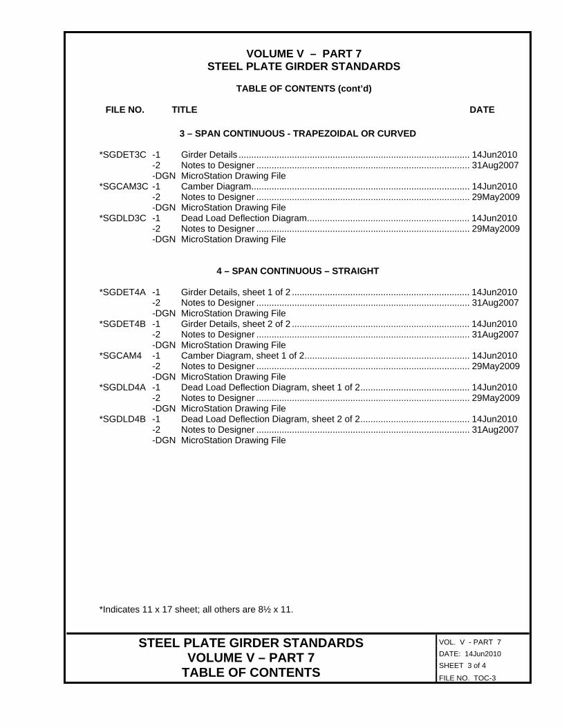
TOC-1 Table of Contents ........................................................................................ 30Aug2012 TOC-2 Table of Contents – cont’d .......................................................................... 14Jun2010 TOC-3 Table of Contents – cont’d .......................................................................... 14Jun2010 TOC-4 Table of Contents – cont’d .......................................................................... 14Jun2010 INSTR-1 General Instructions .................................................................................... 30Aug2012 INSTR-2 External Users: File Access Instructions..................................................... 11Jul2008 INSTR-3 External Users: File Access Instructions..................................................... 11Jul2008
BOLTED SPLICE DETAILS *SGBSPL -1 Bolted Splice Details ................................................................................ 14Jun2010 -2 Notes to Designer .................................................................................... 31Aug2007 -DGN MicroStation Drawing File
SIMPLE SPAN(S) - STRAIGHT *SGDET1A -1 Girder Details, sheet 1 of 2 ...................................................................... 14Jun2010 -2 Notes to Designer .................................................................................... 31Aug2007 -DGN MicroStation Drawing File *SGDET1B -1 Girder Details, sheet 2 of 2 ...................................................................... 14Jun2010 -2 Notes to Designer .................................................................................... 29May2009 -DGN MicroStation Drawing File
SIMPLE SPAN(S) – TRAPEZOIDAL OR CURVED *SGDET1AC-1 Girder Details, sheet 1 of 2 ...................................................................... 14Jun2010 -2 Notes to Designer .................................................................................... 31Aug2007 -DGN MicroStation Drawing File *SGDET1BC-1 Girder Details, sheet 2 of 2 ...................................................................... 14Jun2010 -2 Notes to Designer .................................................................................... 29May2009 -DGN MicroStation Drawing File
*Indicates 11 x 17 sheet; all others are 8½ x 11.

VOLUME V – PART 7
STEEL PLATE GIRDER STANDARDS
TABLE OF CONTENTS (cont’d) FILE NO. TITLE DATE
VOL. V - PART 7
DATE: 14Jun2010
SHEET 2 of 4
STEEL PLATE GIRDER STANDARDS VOLUME V – PART 7
TABLE OF CONTENTS FILE NO. TOC-2
2 – SPAN CONTINUOUS - STRAIGHT *SGDET2 -1 Girder Details ........................................................................................... 14Jun2010 -2 Notes to Designer .................................................................................... 31Aug2007 -DGN MicroStation Drawing File *SGCAM2 -1 Camber Diagram...................................................................................... 14Jun2010 -2 Notes to Designer .................................................................................... 29May2009 -DGN MicroStation Drawing File *SGDLD2 -1 Dead Load Deflection Diagram................................................................ 14Jun2010 -2 Notes to Designer .................................................................................... 29May2009 -DGN MicroStation Drawing File
2 – SPAN CONTINUOUS – TRAPEZOIDAL OR CURVED
*SGDET2C -1 Girder Details ........................................................................................... 14Jun2010 -2 Notes to Designer .................................................................................... 31Aug2007 -DGN MicroStation Drawing File *SGCAM2C -1 Camber Diagram...................................................................................... 14Jun2010 -2 Notes to Designer .................................................................................... 29May2009 -DGN MicroStation Drawing File *SGDLD2C -1 Dead Load Deflection Diagram................................................................ 14Jun2010 -2 Notes to Designer .................................................................................... 29May2009 -DGN MicroStation Drawing File
3 – SPAN CONTINUOUS - STRAIGHT
*SGDET3 -1 Girder Details ........................................................................................... 14Jun2010 -2 Notes to Designer .................................................................................... 31Aug2007 -DGN MicroStation Drawing File *SGCAM3 -1 Camber Diagram...................................................................................... 14Jun2010 -2 Notes to Designer .................................................................................... 29May2009 -DGN MicroStation Drawing File *SGDLD3 -1 Dead Load Deflection Diagram................................................................ 14Jun2010 -2 Notes to Designer .................................................................................... 29May2009 -DGN MicroStation Drawing File
*Indicates 11 x 17 sheet; all others are 8½ x 11.
VOLUME V – PART 7
STEEL PLATE GIRDER STANDARDS
TABLE OF CONTENTS (cont’d) FILE NO. TITLE DATE
VOL. V - PART 7
DATE: 14Jun2010
SHEET 3 of 4
STEEL PLATE GIRDER STANDARDS VOLUME V – PART 7
TABLE OF CONTENTS FILE NO. TOC-3
3 – SPAN CONTINUOUS - TRAPEZOIDAL OR CURVED *SGDET3C -1 Girder Details ........................................................................................... 14Jun2010 -2 Notes to Designer .................................................................................... 31Aug2007 -DGN MicroStation Drawing File *SGCAM3C -1 Camber Diagram...................................................................................... 14Jun2010 -2 Notes to Designer .................................................................................... 29May2009 -DGN MicroStation Drawing File *SGDLD3C -1 Dead Load Deflection Diagram................................................................ 14Jun2010 -2 Notes to Designer .................................................................................... 29May2009 -DGN MicroStation Drawing File
4 – SPAN CONTINUOUS – STRAIGHT
*SGDET4A -1 Girder Details, sheet 1 of 2 ...................................................................... 14Jun2010 -2 Notes to Designer .................................................................................... 31Aug2007 -DGN MicroStation Drawing File *SGDET4B -1 Girder Details, sheet 2 of 2 ...................................................................... 14Jun2010 -2 Notes to Designer .................................................................................... 31Aug2007 -DGN MicroStation Drawing File *SGCAM4 -1 Camber Diagram, sheet 1 of 2................................................................. 14Jun2010 -2 Notes to Designer .................................................................................... 29May2009 -DGN MicroStation Drawing File *SGDLD4A -1 Dead Load Deflection Diagram, sheet 1 of 2........................................... 14Jun2010 -2 Notes to Designer .................................................................................... 29May2009 -DGN MicroStation Drawing File *SGDLD4B -1 Dead Load Deflection Diagram, sheet 2 of 2........................................... 14Jun2010 -2 Notes to Designer .................................................................................... 31Aug2007 -DGN MicroStation Drawing File
*Indicates 11 x 17 sheet; all others are 8½ x 11.
VOLUME V – PART 7
STEEL PLATE GIRDER STANDARDS
TABLE OF CONTENTS (cont’d) FILE NO. TITLE DATE
VOL. V - PART 7
DATE: 14Jun2010
SHEET 4 of 4
STEEL PLATE GIRDER STANDARDS VOLUME V – PART 7
TABLE OF CONTENTS FILE NO. TOC-4
4 – SPAN CONTINUOUS - TRAPEZOIDAL OR CURVED
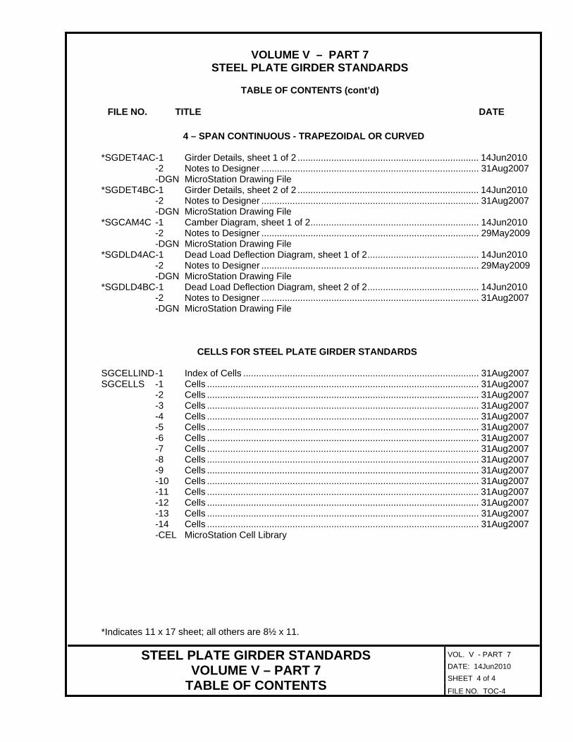
*SGDET4AC-1 Girder Details, sheet 1 of 2 ...................................................................... 14Jun2010 -2 Notes to Designer .................................................................................... 31Aug2007 -DGN MicroStation Drawing File *SGDET4BC-1 Girder Details, sheet 2 of 2 ...................................................................... 14Jun2010 -2 Notes to Designer .................................................................................... 31Aug2007 -DGN MicroStation Drawing File *SGCAM4C -1 Camber Diagram, sheet 1 of 2................................................................. 14Jun2010 -2 Notes to Designer .................................................................................... 29May2009 -DGN MicroStation Drawing File *SGDLD4AC-1 Dead Load Deflection Diagram, sheet 1 of 2........................................... 14Jun2010 -2 Notes to Designer .................................................................................... 29May2009 -DGN MicroStation Drawing File *SGDLD4BC-1 Dead Load Deflection Diagram, sheet 2 of 2........................................... 14Jun2010 -2 Notes to Designer .................................................................................... 31Aug2007 -DGN MicroStation Drawing File
CELLS FOR STEEL PLATE GIRDER STANDARDS
SGCELLIND -1 Index of Cells ........................................................................................... 31Aug2007 SGCELLS -1 Cells ......................................................................................................... 31Aug2007 -2 Cells ......................................................................................................... 31Aug2007 -3 Cells ......................................................................................................... 31Aug2007 -4 Cells ......................................................................................................... 31Aug2007 -5 Cells ......................................................................................................... 31Aug2007 -6 Cells ......................................................................................................... 31Aug2007 -7 Cells ......................................................................................................... 31Aug2007 -8 Cells ......................................................................................................... 31Aug2007 -9 Cells ......................................................................................................... 31Aug2007 -10 Cells ......................................................................................................... 31Aug2007 -11 Cells ......................................................................................................... 31Aug2007 -12 Cells ......................................................................................................... 31Aug2007 -13 Cells ......................................................................................................... 31Aug2007 -14 Cells ......................................................................................................... 31Aug2007 -CEL MicroStation Cell Library
*Indicates 11 x 17 sheet; all others are 8½ x 11.
STEEL PLATE GIRDER STANDARDS GENERAL INSTRUCTIONS
VOL. V - PART 7
DATE: 30Aug2012
SHEET 1of 3
FILE NO. INSTR-1
MANUAL OF THE STRUCTURE AND BRIDGE DIVISION
VOLUME V – PART 7
STEEL PLATE GIRDER STANDARDS
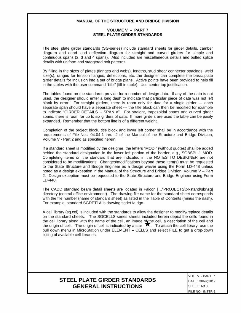
The steel plate girder standards (SG-series) include standard sheets for girder details, camber diagram and dead load deflection diagram for straight and curved girders for simple and continuous spans (2, 3 and 4 spans). Also included are miscellaneous details and bolted splice details with uniform and staggered bolt patterns.
By filling in the sizes of plates (flanges and webs), lengths, stud shear connector spacings, weld size(s), ranges for tension flanges, deflections, etc. the designer can complete the basic plate girder details for inclusion into a set of bridge plans. Active points have been provided to help fill in the tables with the user command “btbl” (fill-in table). Use center top justification.
The tables found on the standards provide for a number of design data. If any of the data is not used, the designer should enter a long dash to indicate that particular piece of data was not left blank by error. For straight girders, there is room only for data for a single girder --- each separate span should have a separate sheet --- the title block can then be modified for example to indicate “GIRDER DETAILS – SPAN a”. For straight, trapezoidal spans and curved girder spans, there is room for up to six girders of data. If more girders are used the table can be easily expanded. Remember that the bottom line is of a different weight. Completion of the project block, title block and lower left corner shall be in accordance with the requirements of File Nos. 04.04-1 thru -2 of the Manual of the Structure and Bridge Division, Volume V - Part 2 and as specified herein. If a standard sheet is modified by the designer, the letters “MOD.” (without quotes) shall be added behind the standard designation in the lower left portion of the border, e.g., SGBSPL-1 MOD. Completing items on the standard that are indicated in the NOTES TO DESIGNER are not considered to be modifications. Changes/modifications beyond these item(s) must be requested to the State Structure and Bridge Engineer as a design waiver using the Form LD-448 unless noted as a design exception in the Manual of the Structure and Bridge Division, Volume V – Part 2. Design exception must be requested to the State Structure and Bridge Engineer using Form LD-440.
The CADD standard beam detail sheets are located in Falcon […\PROJECTS\br-stand\sbr\sg] directory (central office environment). The drawing file name for the standard sheet corresponds with the file number (name of standard sheet) as listed in the Table of Contents (minus the dash). For example, standard SGDET1A is drawing sgdet1a.dgn.
A cell library (sg.cel) is included with the standards to allow the designer to modify/replace details on the standard sheets. The SGCELLS-series sheets included herein depict the cells found in the cell library along with the name of the cell, an image of the cell, a description of the cell and the origin of cell. The origin of cell is indicated by a star . To attach the cell library, use the pull down menu in MicroStation under ELEMENT – CELLS and select FILE to get a drop-down listing of available cell libraries.

VOL. V - PART 7 DATE: 11Jul2008 SHEET 2 of 3
STEEL PLATE GIRDER STANDARDS EXTERNAL DGN FILE ACCESS INSTRUCTIONS
FILE NO. INSTR-2
MANUAL OF THE STRUCTURE AND BRIDGE DIVISION
VOLUME V – PART 7
STEEL PLATE GIRDER STANDARDS For external users, the CADD standard detail sheets are attached to the PDF files for each drawing located on VDOT’s Structure and Bridge Division website. The user will need Adobe Reader version 7.0 or higher to be able to access the files. Either click on the DGN link in the table of contents or click on the attachment tab in the PDF file for each standard sheet.
Using either method, the screen will appear similar to that shown below.
By left clicking on the icon, the following menu will appear:
Users may then save the file to their computer.
VOL. V - PART 7 DATE: 11Jul2008 SHEET 3 of 3
STEEL PLATE GIRDER STANDARDS EXTERNAL DGN FILE ACCESS INSTRUCTIONS
FILE NO. INSTR-3
MANUAL OF THE STRUCTURE AND BRIDGE DIVISION
VOLUME V – PART 7 STEEL PLATE GIRDER STANDARDS
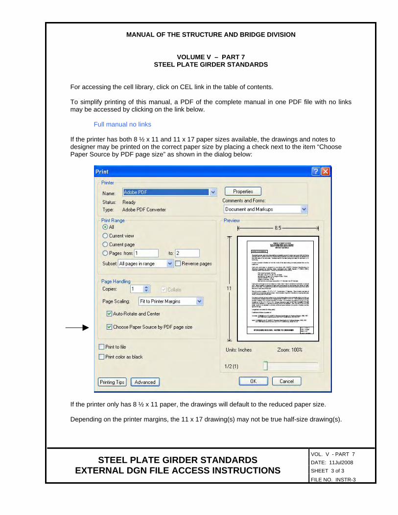
For accessing the cell library, click on CEL link in the table of contents. To simplify printing of this manual, a PDF of the complete manual in one PDF file with no links may be accessed by clicking on the link below. Full manual no links If the printer has both 8 ½ x 11 and 11 x 17 paper sizes available, the drawings and notes to designer may be printed on the correct paper size by placing a check next to the item “Choose Paper Source by PDF page size” as shown in the dialog below:
If the printer only has 8 ½ x 11 paper, the drawings will default to the reduced paper size. Depending on the printer margins, the 11 x 17 drawing(s) may not be true half-size drawing(s).

Notes:
Stud shear connectors on top flange not shown. For spacing, see
girder details, sheet .
BOLTED SPLICE DETAILS
BOLTED SPLICE DETAILS
SGBSPLNot to scaleNot to scale
If Contractor increases the girder web thickness in order to eliminate
the transverse stiffeners, no change will be made in the web splice.
SG
BS
PL
Symm. about L of splice
except as noted
Symm. about
L of girder
TOP FLANGE
=
spa. @
C
C
Symm. about L splice
except as noted
Symm. about
L of girder
BOTTOM FLANGE
=
C
spa. @
C
PL
PL
Symm. about L of splice
except as noted
WEB
2 PL
(one each side of web)
spa.
@
Cas needed
Filler PL
(one each side of web)
2 PL
as needed
Filler PL
(one each side of web)
2 PL
06-14-2010
Date Plan No. Sheet No.Designed: ...........
Drawn: ................
Checked: ............2010, Commonwealth of Virginiac
No. Description Date
STRUCTURE AND BRIDGE DIVISION
COMMONWEALTH OF VIRGINIA
DEPARTMENT OF TRANSPORTATION
Revisions
ROUTE
FEDERAL AID
PROJECT ROUTE PROJECT
STATE SHEET
NO.
VA.
STATEROUTE
FEDERAL AID
PROJECT ROUTE PROJECT
STATE SHEET
NO.
VA.
STATE
STRUCTURAL ENGINEER
RICHMOND, VA
VDOT S&B DIVISION
sgbspl.dgn

VOL. V - PART 7 DATE: 31Aug2007 SHEET 2 of 2
STANDARD SGBSPL: NOTES TO DESIGNER FILE NO. SGBSPL-2
STEEL PLATE GIRDER
BOLTED SPLICE DETAILS
NOTES TO DESIGNER:
Standard is to be used for bolted splices for straight or curved girders, simple and continuous spans. Up to three different splices may be shown on sheet. Designer can modify sheet as needed for bolt pattern in top and bottom flanges by placing the appropriate cell(s) from the cell library. For details of bolted splices, see Manual of the Structure and Bridge Division, Volume V – Part 2, Chapter 11.
ADD THE FOLLOWING NOTES, DIMENSIONS, DETAILS, ETC. TO STANDARD:
NOTES: Add sheet number to first note.
TOP FLANGE: Detail shows 4-2 stagger bolt pattern. See cell library (sg.cel) for other bolt patterns. Add dimensions for gage and pitch of bolts. Show stud shear connectors and spacing thru length of splice if irregular or different from girder detail sheet. Modify girder detail sheet (standard SGDET-series).
WEB: Add dimensions for gage and pitch of bolts. Add plate sizes for splice plates (web and flanges). BOTTOM FLANGE: Detail shows 4-2 stagger bolt pattern. See cell library for other bolt patterns. Add dimensions for gage and pitch of bolts. Show stud shear connectors and spacing thru length of splice if irregular or different from girder detail sheet. Modify girder detail sheet (standard SGDET-series).

PL 8
PL 4
L bearing
Web PL
FA
CB
PL 5PL 6
BT CT DT
GA
CT BT
PL 2
L bearing
CBDB
PL 6
GK
FC
GIRDER ELEVATION
PL 2PL 1
PL 3
AT
PL 7
BB
AT
PL 4
PL 8PL 7
BB ABAB
/
FB
connectors. Align
Span Girder Web PL PL 1 PL 2 PL 3 PL 4 PL 5 PL 6 PL 7 PL 8
AB AT BB BT CB CT DB DT GA GB GC GD GE GF GHSpan Girder
PLATE DIMENSION TABLE
GIRDER DIMENSION TABLE
SG
DE
T1
A
GIRDER DETAILS
SGDET1A
3-�" o stud shear
C
Not to scale
GDGB equal spa.
= GCGE equal spaces = GF
GH GI equal spa.
= GJ
bolted field splice
L permissible
bolted field splice
L permissible �
Typ.C C
FEFD
FA FB FC FD FESpan Girder
GIRDER DIMENSION TABLE
GI GJ GK
PL 3
CSec. 407.04 typ.
VDOT Specs.
or L pier
at abutment
Face of backwall
Cor L pier
at abutment
Face of backwall
C
@ 6"
6 spa.
= 3’-0" = 3’-0"
@ 6"
6 spa. with reinforcing steel.
BEARING STIFFENERS
1" typ.
Detail A
Mill to bear
PL
Typ. when stiffener is
wider than flange
Typ. when stiffener is
narrower than flange
1�" typ.
-
-
DETAIL A
-
Typ. when
stiffener
is narrower
than flange
�" + �"�" + �"
�" + �" both ends
Typ. when
stiffener
is wider
than flange
-�" + �"
CROSS FRAME
CONNECTOR PLATE
Detail A
Detail A
PL
1�"
�
�
1�"TRANSVERSE INTERMEDIATE
STIFFENER
PL
Detail A
See Note A
1�"
1�"
�
Tight fit to tension flange(s).
to compression flange(s).
Note A: �" fillet weld (both sides)
�
/Symbol o = diameter.
field splice, see bolted splice details, sheet .
For stud shear connector spacing in vicinity of permissible bolted
stress for Charpy V-Notch impact requirements.
The bottom flange, web, and all splice plates are areas of tensile
sheet .
For spacing of transverse intermediate stiffeners, see framing plan,
mediate stiffeners by increasing the web thickness to .
The Contractor has the option of eliminating the transverse inter-
Notes:
06-14-2010
Date Plan No. Sheet No.Designed: ...........
Drawn: ................
Checked: ............2010, Commonwealth of Virginiac
No. Description Date
STRUCTURE AND BRIDGE DIVISION
COMMONWEALTH OF VIRGINIA
DEPARTMENT OF TRANSPORTATION
Revisions
ROUTE
FEDERAL AID
PROJECT ROUTE PROJECT
STATE SHEET
NO.
VA.
STATEROUTE
FEDERAL AID
PROJECT ROUTE PROJECT
STATE SHEET
NO.
VA.
STATE
STRUCTURAL ENGINEER
RICHMOND, VA
VDOT S&B DIVISION
sgdet1a.d
gn
VOL. V - PART 7 DATE: 31Aug2007 SHEET 2 of 2
STANDARD SGDET1A: NOTES TO DESIGNER FILE NO. SGDET1A-2
STEEL PLATE GIRDER
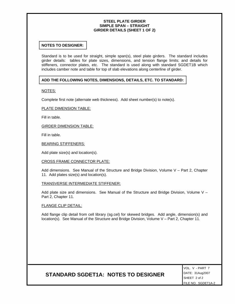
SIMPLE SPAN – STRAIGHT GIRDER DETAILS (SHEET 1 OF 2)
NOTES TO DESIGNER:
Standard is to be used for straight, simple span(s), steel plate girders. The standard includes girder details: tables for plate sizes, dimensions, and tension flange limits; and details for stiffeners, connector plates, etc. The standard is used along with standard SGDET1B which includes camber note and table for top of slab elevations along centerline of girder.
ADD THE FOLLOWING NOTES, DIMENSIONS, DETAILS, ETC. TO STANDARD:
NOTES:
Complete first note (alternate web thickness). Add sheet number(s) to note(s).
PLATE DIMENSION TABLE: Fill in table. GIRDER DIMENSION TABLE:
Fill in table.
BEARING STIFFENERS: Add plate size(s) and location(s).
CROSS FRAME CONNECTOR PLATE: Add dimensions. See Manual of the Structure and Bridge Division, Volume V – Part 2, Chapter 11. Add plates size(s) and location(s).
TRANSVERSE INTERMEDIATE STIFFENER: Add plate size and dimensions. See Manual of the Structure and Bridge Division, Volume V – Part 2, Chapter 11.
FLANGE CLIP DETAIL: Add flange clip detail from cell library (sg.cel) for skewed bridges. Add angle, dimension(s) and location(s). See Manual of the Structure and Bridge Division, Volume V – Part 2, Chapter 11.

Adjustment of deck slab forms to correct for dead load deflections shall be made
slab thickness. Longitudinal screed should be set above final finished grade by amounts
equal to .c
c
= Deflection of girder from dead load of concrete
deck slab and bolsters.
= Deflection of girder from dead load (e.g. parapet)
added after deck slab is cast.
Camber Note:
Dead Load Deflection at a Dead Load Deflection at b
c c
girder from its own weight after erection, including struts (diaphragms),
connectors, etc., at midspan.
DEAD LOAD DEFLECTION DIAGRAM
Girder sC
s= Deflection of girder from its own weight after
erection including diaphragms, connectors, etc.
at midspan.
Girders shall be cambered up C at midspan. Computed deflection of
s
TOP OF SLAB ELEVATIONS ALONG L GIRDERC
Girder 1 2 3 54
2 3 4 51
Face of backwall
at abutment
or L pier
L bearing
PLANShowing points of top of slab elevations
6 7 8 9 10 11
Face of backwall
at abutment
or L pier
L bearing
10986 7 11
10 equal spaces
GIRDER DETAILS
SGDET1B
C
C C
by varying thickness of concrete bolster between slab and girder without alteration of
Not to scale
SG
DE
T1
B
CL girderC
’s ’s
’s
C = The required upward camber for girder at midspan.
Shape of top of form (bottom of deck slab)
after deflection from total dead load added
Shape of top of form before
any deck slab concrete is
placed. Top of form to be
nowhere above this line.
Computed finished grade after
L/4 L/4 L/4 L/4
ab b L bearingL bearing
see table below
CC
slab thickness
" minimum
= ’s + c
06-14-2010
after erection of structural steel
full dead load deflection
Date Plan No. Sheet No.Designed: ...........
Drawn: ................
Checked: ............2010, Commonwealth of Virginiac
No. Description Date
STRUCTURE AND BRIDGE DIVISION
COMMONWEALTH OF VIRGINIA
DEPARTMENT OF TRANSPORTATION
Revisions
ROUTE
FEDERAL AID
PROJECT ROUTE PROJECT
STATE SHEET
NO.
VA.
STATEROUTE
FEDERAL AID
PROJECT ROUTE PROJECT
STATE SHEET
NO.
VA.
STATE
STRUCTURAL ENGINEER
RICHMOND, VA
VDOT S&B DIVISION
sgdet1b.d
gn

VOL. V - PART 7 DATE: 29May2009 SHEET 2 of 2
STANDARD SGDET1B: NOTES TO DESIGNER FILE NO. SGDET1B-2
STEEL PLATE GIRDER
SIMPLE SPAN – STRAIGHT GIRDER DETAILS (SHEET 2 OF 2)
NOTES TO DESIGNER: Standard is to be used for straight, simple span(s), steel plate girders. The standard includes dead load deflection diagram, camber note, and table for top of slab elevations along centerline girder. The standard is used along with standard SGDET1A which includes girder details: tables for plate sizes, dimensions and tension flange limits; and details for stiffeners, connector plates, etc.
ADD THE FOLLOWING NOTES, DIMENSIONS, DETAILS, ETC. TO STANDARD:
NOTES: Deflected shape is shown for hump vertical curve and may be replaced with other shape(s) (straight gradient, sag vertical curve) in the cell library. See file no. SGCELLS for modification with other cells.
Add dimension for minimum slab thickness in dead load deflection diagram. Fill in table. Show
values using 1/8” increments.
TOP OF SLAB ELEVATIONS ALONG CENTERLINE GIRDER: Fill in table.

PL 8
PL 4
L bearing
Web PL
FA
CB
PL 5PL 6
BT CT DT
GA
CT BT
PL 2
L bearing
CBDB
PL 6
GK
GIRDER ELEVATION
PL 2 PL 1PL 3
AT
PL 7
BB
AT
PL 4PL 3
PL 8PL 7
BB ABAB
/
Span Girder Web PL PL 1 PL 2 PL 3 PL 4 PL 5 PL 6 PL 7 PL 8
AB AT BB BT CB CT DB DT GA
FB
Span Girder
PLATE DIMENSION TABLE
GIRDER DIMENSION TABLE
connectors. Align
SG
DE
T1
AC
GIRDER DETAILS
SGDET1AC
3-�" o stud shear
Not to scale
FA FB FC FD FESpan Girder
GIRDER DIMENSION TABLE
GB GC GD GE GF GH GI GJ GK
Typ.
�
Radius
GH GI equal spa.
= GJ
GDGB egual spa.
= GCGE equal spaces = GF
bolted field splice
L permissibleC
bolted field splice
L permissibleC
FD FE
C
FC
C
Sec. 407.04 typ.
VDOT Specs.
or L pier
at abutment
Face of backwall
Cor L pier
at abutment
Face of backwall
C
with reinforcing steel.
@ 6"
6 spa.
= 3’-0"
@ 6"
6 spa.
= 3’-0"
BEARING STIFFENERS
1" typ.
Detail A
Mill to bear
PL
Typ. when stiffener is
wider than flange
Typ. when stiffener is
narrower than flange
1�" typ. -
-
DETAIL A
-
Typ. when
stiffener
is narrower
than flange
�" + �"�" + �"
�" + �" both ends
Typ. when
stiffener
is wider
than flange
-�" + �"
CROSS FRAME
CONNECTOR PLATE
Detail A
Detail A
PL
1�"
�
�
1�"
TRANSVERSE INTERMEDIATE
STIFFENER
PL
Detail A
See Note A
1�"
1�"
�
Tight fit to tension flange(s).
to compression flange(s).
Note A: �" fillet weld (both sides)
�
/Symbol o = diameter.
field splice, see bolted splice details, sheet .
For stud shear connector spacing in vicinity of permissible bolted
stress for Charpy V-Notch impact requirements.
The bottom flange, web, and all splice plates are areas of tensile
sheet .
For spacing of transverse intermediate stiffeners, see framing plan,
mediate stiffeners by increasing the web thickness to .
The Contractor has the option of eliminating the transverse inter-
Notes:
06-14-2010
Date Plan No. Sheet No.Designed: ...........
Drawn: ................
Checked: ............2010, Commonwealth of Virginiac
No. Description Date
STRUCTURE AND BRIDGE DIVISION
COMMONWEALTH OF VIRGINIA
DEPARTMENT OF TRANSPORTATION
Revisions
ROUTE
FEDERAL AID
PROJECT ROUTE PROJECT
STATE SHEET
NO.
VA.
STATEROUTE
FEDERAL AID
PROJECT ROUTE PROJECT
STATE SHEET
NO.
VA.
STATE
STRUCTURAL ENGINEER
RICHMOND, VA
VDOT S&B DIVISION
sgdet1ac.d
gn
VOL. V - PART 7 DATE: 31Aug2007 SHEET 2 of 2
STANDARD SGDET1AC: NOTES TO DESIGNER FILE NO. SGDET1AC-2
STEEL PLATE GIRDER
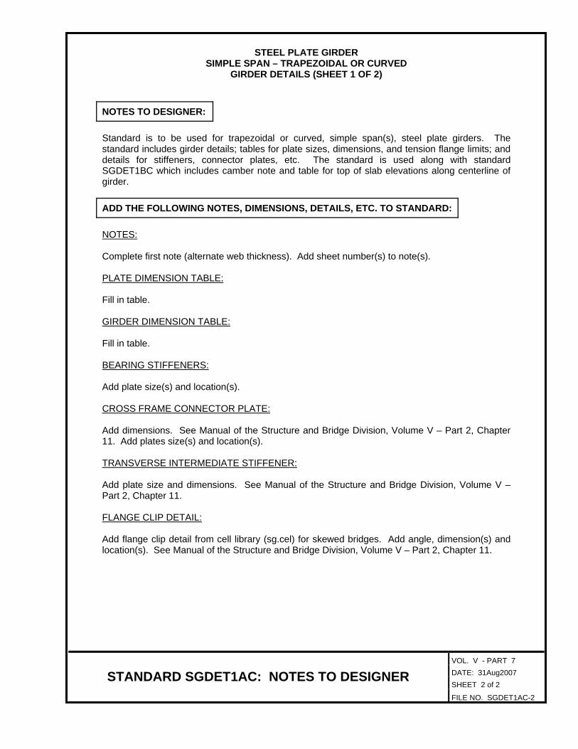
SIMPLE SPAN – TRAPEZOIDAL OR CURVED GIRDER DETAILS (SHEET 1 OF 2)
NOTES TO DESIGNER:
Standard is to be used for trapezoidal or curved, simple span(s), steel plate girders. The standard includes girder details; tables for plate sizes, dimensions, and tension flange limits; and details for stiffeners, connector plates, etc. The standard is used along with standard SGDET1BC which includes camber note and table for top of slab elevations along centerline of girder.
ADD THE FOLLOWING NOTES, DIMENSIONS, DETAILS, ETC. TO STANDARD:
NOTES: Complete first note (alternate web thickness). Add sheet number(s) to note(s).
PLATE DIMENSION TABLE: Fill in table. GIRDER DIMENSION TABLE:
Fill in table.
BEARING STIFFENERS: Add plate size(s) and location(s).
CROSS FRAME CONNECTOR PLATE: Add dimensions. See Manual of the Structure and Bridge Division, Volume V – Part 2, Chapter 11. Add plates size(s) and location(s).
TRANSVERSE INTERMEDIATE STIFFENER:
Add plate size and dimensions. See Manual of the Structure and Bridge Division, Volume V – Part 2, Chapter 11.
FLANGE CLIP DETAIL: Add flange clip detail from cell library (sg.cel) for skewed bridges. Add angle, dimension(s) and location(s). See Manual of the Structure and Bridge Division, Volume V – Part 2, Chapter 11.

SG
DE
T1
BC
Adjustment of deck slab forms to correct for dead load deflections shall be made
slab thickness. Longitudinal screed should be set above final finished grade by amounts
equal to .c
c
= Deflection of girder from dead load of concrete
deck slab and bolsters.
= Deflection of girder from dead load (e.g. parapet)
added after deck slab is cast.
Camber Note:
Dead Load Deflection at a Dead Load Deflection at b
c c
girder from its own weight after erection, including struts (diaphragms),
connectors, etc., at midspan.
DEAD LOAD DEFLECTION DIAGRAM
Girder sC
s= Deflection of girder from its own weight after
erection including diaphragms, connectors, etc.
at midspan.
Girders shall be cambered up C at midspan. Computed deflection of
s
TOP OF SLAB ELEVATIONS ALONG L GIRDERC
Girder 1 2 3 54
2 3 4 5
L girder
1
L bearing
Showing points of top of slab elevations
6 7 8 9 10 11
L bearing
10986 7 11
10 equal spaces
GIRDER DETAILS
SGDET1BC
by varying thickness of concrete bolster between slab and girder without alteration of
Not to scale
CC C
C C
’s’s
’s
C = The required upward camber for girder at midspan.
Face of backwall
at abutment
or L pier
Face of backwall
at abutment
or L pier
PLAN
Shape of top of form (bottom of deck slab)
after deflection from total dead load added
Shape of top of form before
any deck slab concrete is
placed. Top of form to be
nowhere above this line.
Computed finished grade after
L/4 L/4 L/4 L/4
ab b L bearingL bearing
see table below
CC
slab thickness
" minimum
= ’s + c
06-14-2010
full dead load deflection
after erection of structural steel
Date Plan No. Sheet No.Designed: ...........
Drawn: ................
Checked: ............2010, Commonwealth of Virginiac
No. Description Date
STRUCTURE AND BRIDGE DIVISION
COMMONWEALTH OF VIRGINIA
DEPARTMENT OF TRANSPORTATION
Revisions
ROUTE
FEDERAL AID
PROJECT ROUTE PROJECT
STATE SHEET
NO.
VA.
STATEROUTE
FEDERAL AID
PROJECT ROUTE PROJECT
STATE SHEET
NO.
VA.
STATE
STRUCTURAL ENGINEER
RICHMOND, VA
VDOT S&B DIVISION
sgdet1bc.d
gn

VOL. V - PART 7 DATE: 29May2009 SHEET 2 of 2
STANDARD SGDET1BC: NOTES TO DESIGNER FILE NO. SGDET1BC-2
STEEL PLATE GIRDER
SIMPLE SPAN – TRAPEZOIDAL OR CURVED GIRDER DETAILS (SHEET 2 OF 2)
NOTES TO DESIGNER:
Standard is to be used for trapezoidal or curved, simple span(s), steel plate girders. The standard includes dead load deflection diagram, camber note, and table for top of slab elevations along centerline girder. The standard is used along with standard SGDET1AC which includes girder details; tables for plate sizes, dimensions and tension flange limits; and details for stiffeners, connector plates, etc.
ADD THE FOLLOWING NOTES, DIMENSIONS, DETAILS, ETC. TO STANDARD:
NOTES:
Deflected shape is shown for hump vertical curve and may be replaced with other shape(s) (straight gradient, sag vertical curve) in the cell library (sg.cel).
Add dimension for minimum slab thickness in dead load deflection diagram. Fill in table. Show values using 1/8” increments.
TOP OF SLAB ELEVATIONS ALONG CENTERLINE GIRDER: Fill in table.

Girder PL 1 PL 2 PL 3 PL 4 PL 5 PL 6 PL 7 PL 8 PL 9 PL 10
PLATE DIMENSION TABLE
GIRDER DIMENSION TABLE
PL 8
PL 1
L bearing
Web PL
JA
AB CB
PL 11PL 10
AT CT DT
DB
KA
ET FT GT
PL 7
PL 5
PL 14
L bearing
GBFBEB
JC
�
PL 12
KP
GIRDER ELEVATION
T2 T3
Tension flange topTension flange top
Tension flange bottom
T1
Tension flange bottom
T1 T2 T3 T4
TENSION FLANGES
PL 3PL 4
PL 11 PL 12 PL 13 PL 14
PL 9
BB
BT
PL 2
HT
HB
PL 6
PL 13
nectors per row. Align
with reinforcing steel.
/
JB JD
Typ.
Girder AB AT BB BT CB CT DB DT EB ET FB FT GB GT HB HT
= 3’-0" = 3’-0"
GIRDER DETAILS
SGDET2
SG
DE
T2
3 -�" o stud shear con-
Web PL
Girder
Not to scale
bolted field splice
L permissible
JE JF
KN equal spa.
= KOKL equal spa. = KM
KI equal spa.
= KJ
KG equal spa.
= KH
KF KKKD equal spa.
= KE
KB equal spa.
= KC
L bearing and L pier
CC
T4
C C
CC
/
Sec. 407.04 typ.
VDOT Specs.
C C
bolted field splice
L permissible
Face of backwall
or L pier
Face of backwall
or L pier
Symbol o = diameter.
impact requirements.
and all splice plates are areas of tensile stress for Charpy V-Notch
The top and bottom flanges as shown in Girder Elevation, the web
bolted field splice, see bolted splice details, sheet .
For spacing of stud shear connectors in vicinity of permissible
mediate web stiffener PL’s, see Framing Plan, sheet .
For spacing of intermediate diaphragm connector PL’s and inter-
stiffeners by increasing the web thickness to .
The Contractor has the option of eliminating the intermediate web
Notes:
@ 6"
6 spa.
@ 6"
6 spa.
GIRDER DIMENSION TABLE
Girder KIJA JC JD JE JF KA KBJB KC KD KE KF KG KH KJ KK KNKL KM KO KP
BEARING STIFFENERS
1" typ.
Detail A
Mill to bear
PL
Typ. when stiffener is
wider than flange
Typ. when stiffener is
narrower than flange
1�" typ.-
-
DETAIL A
-
Typ. when
stiffener
is narrower
than flange
�" + �"�" + �"
�" + �" both ends
Typ. when
stiffener
is wider
than flange
-�" + �"
CROSS FRAME
CONNECTOR PLATE
Detail A
Detail A
PL
1�"
�
�
1�"
Tight fit to tension flange(s).
to compression flange(s).
Note A: �" fillet weld (both sides)
�
TRANSVERSE INTERMEDIATE
STIFFENER
PL
Detail A
See Note A
1�"
1�"
�
06-14-2010
Date Plan No. Sheet No.Designed: ...........
Drawn: ................
Checked: ............2010, Commonwealth of Virginiac
No. Description Date
STRUCTURE AND BRIDGE DIVISION
COMMONWEALTH OF VIRGINIA
DEPARTMENT OF TRANSPORTATION
Revisions
ROUTE
FEDERAL AID
PROJECT ROUTE PROJECT
STATE SHEET
NO.
VA.
STATEROUTE
FEDERAL AID
PROJECT ROUTE PROJECT
STATE SHEET
NO.
VA.
STATE
STRUCTURAL ENGINEER
RICHMOND, VA
VDOT S&B DIVISION
sgdet2.d
gn

VOL. V - PART 7 DATE: 31Aug2007 SHEET 2 of 2
STANDARD SGDET2: NOTES TO DESIGNER FILE NO. SGDET2-2
STEEL PLATE GIRDER
2-SPAN CONTINUOUS - STRAIGHT GIRDER DETAILS
NOTES TO DESIGNER:
Standard is to be used for straight, 2-span continuous, steel plate girders. The standard includes girder details; tables for plate sizes, dimensions, and tension flange limits; and details for stiffeners, connector plates, etc. The standard is used along with standards SGCAM2 (camber diagram) and SGDLD2 (dead load deflection and top of slab elevations along centerline girder).
ADD THE FOLLOWING NOTES, DIMENSIONS, DETAILS, ETC. TO STANDARD:
NOTES:
Complete first note (alternate web thickness). Add sheet number(s) to note(s).
PLATE DIMENSION TABLE:
Fill in table.
TENSION FLANGES: Fill in table.
GIRDER DIMENSION TABLE:
Fill in table.
BEARING STIFFENERS: Add plate size(s) and location(s).
CROSS FRAME CONNECTOR PLATE: Add dimensions. See Manual of the Structure and Bridge Division, Volume V – Part 2, Chapter 11. Add plates size(s) and location(s).
TRANSVERSE INTERMEDIATE STIFFENER: Add plate size and dimensions. See Manual of the Structure and Bridge Division, Volume V – Part 2, Chapter 11.
FLANGE CLIP DETAIL:
Add flange clip detail from cell library (see file no. SGCELLS) for skewed bridges. Add angle, dimension(s) and location(s). Details may have to be moved to place cell. See Manual of the Structure and Bridge Division, Volume V – Part 2, Chapter 11.

Girder
s
’s
c
H
Total
H
Total
H
Total
H
Total
H
Total
H
Total
Girders
All
Girder
Girder
Girder
Girder
Girder
Girder
CAMBER
SG
CA
M2
CAMBER DIAGRAM
SGCAM2
Not to scale
c
= Deflection of girder from dead load of concrete
deck slab and bolsters.
= Deflection of girder from dead load (e.g. parapet)
added after deck slab is cast.
’s
s= Deflection of girder from its own weight after
erection including diaphragms, connectors, etc.
top of web at any point being considered.
H = Distance between horizontal reference line and deflected
MidpointL permissible spliceMidpoint
Horiz. reference line
Top of web as fabricated
Deflected top of
web without CT
H
s + ’s + c + H
at
L bearingC
at
L bearingCCat
L bearingC
06-14-2010
Date Plan No. Sheet No.Designed: ...........
Drawn: ................
Checked: ............2010, Commonwealth of Virginiac
No. Description Date
STRUCTURE AND BRIDGE DIVISION
COMMONWEALTH OF VIRGINIA
DEPARTMENT OF TRANSPORTATION
Revisions
ROUTE
FEDERAL AID
PROJECT ROUTE PROJECT
STATE SHEET
NO.
VA.
STATEROUTE
FEDERAL AID
PROJECT ROUTE PROJECT
STATE SHEET
NO.
VA.
STATE
STRUCTURAL ENGINEER
RICHMOND, VA
VDOT S&B DIVISION
sgca
m2.d
gn

VOL. V - PART 7 DATE: 29May2009 SHEET 2 of 2
STANDARD SGCAM2: NOTES TO DESIGNER FILE NO. SGCAM2-2
STEEL PLATE GIRDER
2-SPAN CONTINUOUS - STRAIGHT CAMBER DIAGRAM
NOTES TO DESIGNER:
Standard is to be used for straight, 2-span continuous, steel plate girders. The standard includes the camber diagram and table for deflections. The standard is used along with standards SGDET2 (girder details) and SGDLD2 (dead load deflections and top of slab elevations along centerline girder).
ADD THE FOLLOWING NOTES, DIMENSIONS, DETAILS, ETC. TO STANDARD:
CAMBER DIAGRAM: Detail shows hump vertical curve with left support at a higher elevation than right support. Detail may be replaced with other shapes in cell library (sg.cel).
Fill in dimensions on diagram and fill in table. Show values using 1/8” increments.

Finished grade after
full dead load deflection
Top of web after full
dead load deflection
Top of web after
deflection from
steel dead load only
10 11 12 13 14 15 16 17 18 19 20
10 equal spaces
10 11 12 13 14 15 16 17 18 19 20
21 22 23 24 25 26 27 28 29 30
21 22 23 24 25 26 27 28 29 30
10 equal spaces
Point
Total
All values in Dead Load Deflection Table are in inches.
DEAD LOAD DEFLECTIONS
10 11 12 13 14 15 16 17 18 19 20 21 22 23 24 25 26 27 28 29 30Point
Girder
Girder
Girder
Girder
Girder
Girder
TOP OF SLAB ELEVATIONS ALONG L GIRDERC
Girder
SG
DL
D2
SGDLD2
c
= Deflection of girder from dead load of concrete
deck slab and bolsters.
= Deflection of girder from dead load (e.g. parapet)
added after deck slab is cast.
’s
Not to scale
at
L bearingC
at
L bearingat
L bearingC C
AND SLAB ELEVATIONS
DEAD LOAD DEFLECTIONS
c
’s
06-14-2010
Date Plan No. Sheet No.Designed: ...........
Drawn: ................
Checked: ............2010, Commonwealth of Virginiac
No. Description Date
STRUCTURE AND BRIDGE DIVISION
COMMONWEALTH OF VIRGINIA
DEPARTMENT OF TRANSPORTATION
Revisions
ROUTE
FEDERAL AID
PROJECT ROUTE PROJECT
STATE SHEET
NO.
VA.
STATEROUTE
FEDERAL AID
PROJECT ROUTE PROJECT
STATE SHEET
NO.
VA.
STATE
STRUCTURAL ENGINEER
RICHMOND, VA
VDOT S&B DIVISION
sgdld
2.d
gn
VOL. V - PART 7 DATE: 29May2009 SHEET 2 of 2
STANDARD SGDLD2: NOTES TO DESIGNER FILE NO. SGDLD2-2
STEEL PLATE GIRDER
2-SPAN CONTINUOUS – STRAIIGHT DEAD LOAD DEFLECTION
NOTES TO DESIGNER:
Standard is to be used for straight, 2-span continuous, steel plate girders. The standard includes table for deflections and table for top of slab elevations along centerline girder. The standard is used along with standards SGDET2 (girder details) and SGCAM2 (camber diagram).
ADD THE FOLLOWING NOTES, DIMENSIONS, DETAILS, ETC. TO STANDARD:
DEAD LOAD DEFLECTION DIAGRAM:
Fill in table of dead load deflections. Show values using 1/8” increments.
TOP OF SLAB ELEVATIONS ALONG CENTERLINE GIRDER:
Fill in table.
PL 1 PL 2 PL 3 PL 4 PL 5 PL 6 PL 7 PL 8 PL 9 PL 10
PLATE DIMENSION TABLE
GIRDER DIMENSION TABLE
PL 8
PL 1
L bearing
Web PL
JA
AB CB
PL 11PL 10
AT CT DT
DB
KA
ET FT GT
PL 7PL 5
PL 14
L bearing
GBFBEB
JC
�
PL 12
KP
GIRDER ELEVATION
T2 T3
Tension flange topTension flange top
T4
Tension flange bottom
T1
Tension flange bottom
PL 3PL 4
PL 11 PL 12 PL 13 PL 14
PL 9
BB
BT
PL 2
HT
HB
PL 6
PL 13
nectors per row. Align
with reinforcing steel.
/
JB JD
Typ.
Girder AB AT BB BT CB CT DB DT EB ET FB FT GB GT HB HT
=3’-0" = 3’-0"
GIRDER DETAILS
SGDET2C
SG
DE
T2
C3 -�" o stud shear con-
Web PL
Not to scale
KB equal spa.
= KC
KD equal spa.
= KE
KF
= KH
KI equal spa.
= KJ
KKKL equal spa. = KM
KN equal spa.
= KO
bolted field splice
L permissiblebolted field splice
L permissible
JE JF
L bearing and L pier
CC
6 spa. @ 6" KG equal spa. 6 spa. @ 6"
Girder
C
C C
C C
C
Sec. 407.04 typ.
VDOT Specs.
Face of backwall
or L pier
Face of backwall
or L pier
/Symbol o = diameter.
impact requirements.
and all splice plates are areas of tensile stress for Charpy V-Notch
The top and bottom flanges as shown in Girder Elevation, the web
bolted field splice, see bolted splice details, sheet .
For spacing of stud shear connectors in vicinity of permissible
mediate web stiffener PL’s, see Framing Plan, sheet .
For spacing of intermediate diaphragm connector PL’s and inter-
stiffeners by increasing the web thickness to .
The Contractor has the option of eliminating the intermediate web
Notes:
GIRDER DIMENSION TABLE
Girder JC JD JE JFJA JB KA KEKDKB KC KF KG KH KI KJ KK KL KM KN KO KP Radius
Tight fit to tension flange(s).
to compression flange(s).
Note A: �" fillet weld (both sides)
BEARING STIFFENERS
1" typ.
Detail A
Mill to bear
PL
Typ. when stiffener is
wider than flange
Typ. when stiffener is
narrower than flange
1�" typ.-
-
DETAIL A
-
Typ. when
stiffener
is narrower
than flange
�" + �"�" + �"
�" + �" both ends
Typ. when
stiffener
is wider
than flange
-�" + �"
TRANSVERSE INTERMEDIATE
STIFFENER
PL
Detail A
See Note A
1�"
1�"
�
CROSS FRAME
CONNECTOR PLATE
Detail A
Detail A
PL
1�"
�
�
1�"
�
T1 T2 T3 T4
TENSION FLANGES
Girder
06-14-2010
Date Plan No. Sheet No.Designed: ...........
Drawn: ................
Checked: ............2010, Commonwealth of Virginiac
No. Description Date
STRUCTURE AND BRIDGE DIVISION
COMMONWEALTH OF VIRGINIA
DEPARTMENT OF TRANSPORTATION
Revisions
ROUTE
FEDERAL AID
PROJECT ROUTE PROJECT
STATE SHEET
NO.
VA.
STATEROUTE
FEDERAL AID
PROJECT ROUTE PROJECT
STATE SHEET
NO.
VA.
STATE
STRUCTURAL ENGINEER
RICHMOND, VA
VDOT S&B DIVISION
sgdet2c.d
gn

VOL. V - PART 7 DATE: 31Aug2007 SHEET 2 of 2
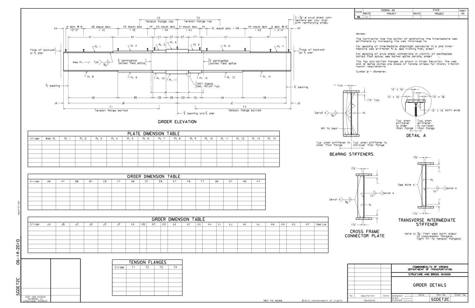
STANDARD SGDET2C: NOTES TO DESIGNER FILE NO. SGDET2C-2
STEEL PLATE GIRDER
2-SPAN CONTINUOUS – TRAPEZOIDAL OR CURVED GIRDER DETAILS
NOTES TO DESIGNER:
Standard is to be used for trapezoidal or curved, 2-span continuous, steel plate girders. The standard includes girder details; tables for plate sizes, dimensions, and tension flange limits; and details for stiffeners, connector plates, etc. The standard is used along with standards SGCAM2C (camber diagram) and SGDLD2C (dead load deflection and top of slab elevations along centerline girder).
ADD THE FOLLOWING NOTES, DIMENSIONS, DETAILS, ETC. TO STANDARD:
NOTES: Complete first note (alternate web thickness). Add sheet number(s) to note(s).
PLATE DIMENSION TABLE: Fill in table.
TENSION FLANGES: Fill in table.
GIRDER DIMENSION TABLE:
Fill in table.
BEARING STIFFENERS: Add plate size(s) and location(s).
CROSS FRAME CONNECTOR PLATE: Add dimensions. See Manual of the Structure and Bridge Division, Volume V – Part 2, Chapter 11. Add plates size(s) and location(s).
TRANSVERSE INTERMEDIATE STIFFENER: Add plate size and dimensions. See Manual of the Structure and Bridge Division, Volume V – Part 2, Chapter 11.
FLANGE CLIP DETAIL: Add flange clip detail from cell library (sg.cel) for skewed bridges. Add angle, dimension(s) and location(s). Details may have to be moved to place cell. See Manual of the Structure and Bridge Division, Volume V – Part 2, Chapter 11.

s
’s
c
H
Total
Girder
s
’s
c
H
Total
s
’s
c
H
Total
s
’s
c
H
Total
s
’s
c
H
Total
s
’s
c
H
Total
CAMBER
Girder
Girder
Girder
Girder
Girder
Girder
Girder
Girder
Girder
Girder
Girder
SG
CA
M2
C
CAMBER DIAGRAM
SGCAM2C
c
= Deflection of girder from dead load of concrete
deck slab and bolsters.
= Deflection of girder from dead load (e.g. parapet)
added after deck slab is cast.
s= Deflection of girder from its own weight after
erection including diaphragms, connectors, etc.
top of web at any point being considered.
H = Distance between horizontal reference line and deflected
Not to scale
’s
MidpointL permissible spliceMidpoint
Horiz. reference line
Top of web as fabricated
Deflected top of
web without CT
H
s + ’s + c + H
at
L bearingC
at
L bearingCCat
L bearingC
06-14-2010
Date Plan No. Sheet No.Designed: ...........
Drawn: ................
Checked: ............2010, Commonwealth of Virginiac
No. Description Date
STRUCTURE AND BRIDGE DIVISION
COMMONWEALTH OF VIRGINIA
DEPARTMENT OF TRANSPORTATION
Revisions
ROUTE
FEDERAL AID
PROJECT ROUTE PROJECT
STATE SHEET
NO.
VA.
STATEROUTE
FEDERAL AID
PROJECT ROUTE PROJECT
STATE SHEET
NO.
VA.
STATE
STRUCTURAL ENGINEER
RICHMOND, VA
VDOT S&B DIVISION
sgca
m2c.d
gn

VOL. V - PART 7 DATE: 29May2009 SHEET 2 of 2
STANDARD SGCAM2C: NOTES TO DESIGNER FILE NO. SGCAM2C-2
STEEL PLATE GIRDER
2-SPAN CONTINUOUS – TRAPEZOIDAL OR CURVED CAMBER DIAGRAM
NOTES TO DESIGNER:
Standard is to be used for trapezoidal or curved, 2-span continuous, steel plate girders. The standard includes the camber diagram and table for deflections. The standard is used along with standards SGDET2C (girder details) and SGDLD2C (dead load deflections and top of slab elevations along centerline girder).
ADD THE FOLLOWING NOTES, DIMENSIONS, DETAILS, ETC. TO STANDARD:
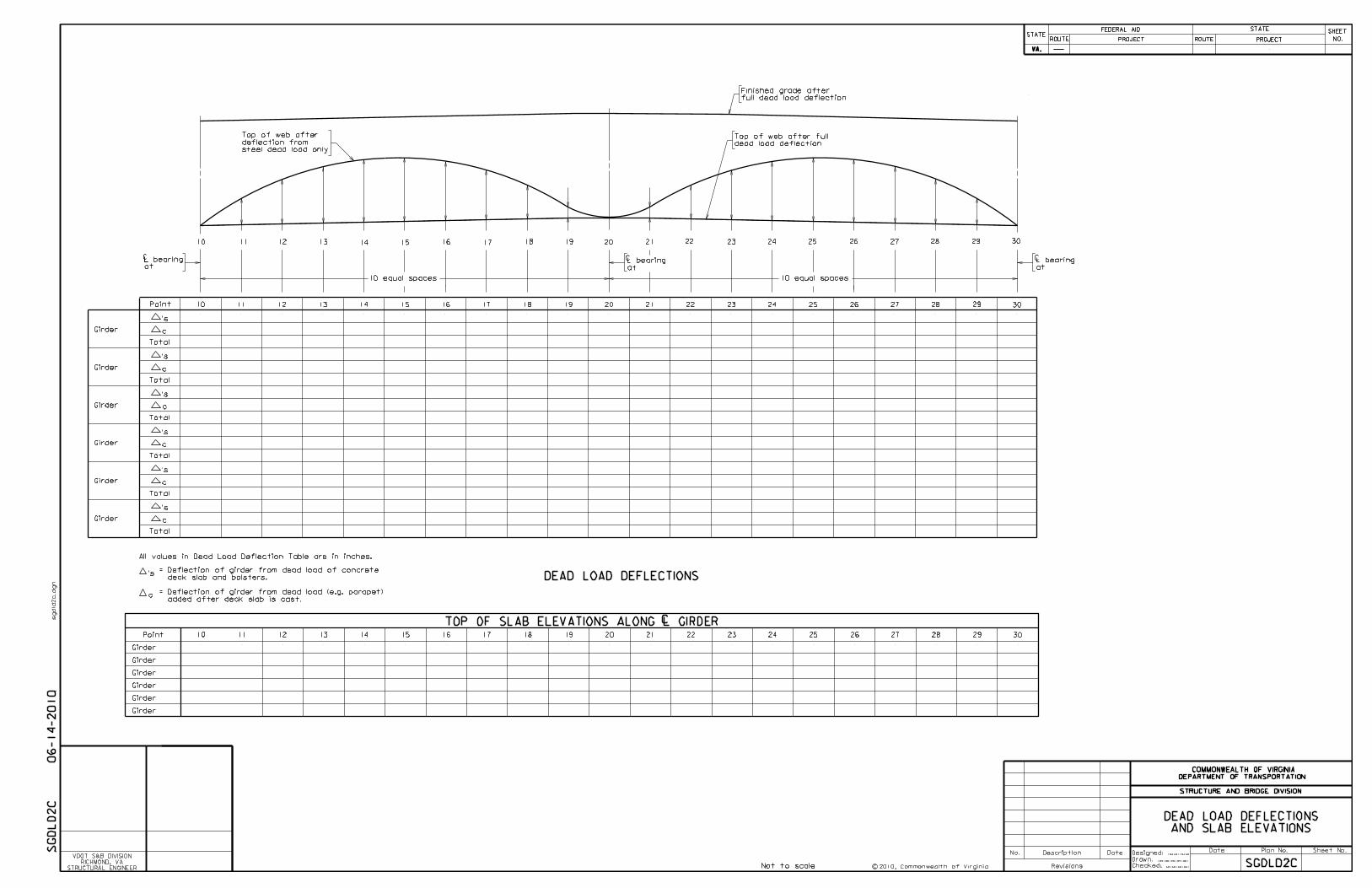
CAMBER DIAGRAM: Detail shows hump vertical curve with left support at a higher elevation than right support. Detail may be replaced with other shapes in cell library (sg.cel).
Fill in dimensions on diagram and fill in table. Show values using 1/8” increments.
SGDLD2C
Finished grade after
full dead load deflection
Top of web after full
dead load deflection
Top of web after
deflection from
steel dead load only
10 11 12 13 14 15 16 17 18 19 20
10 equal spaces
10 11 12 13 14 15 16 17 18 19 20
21 22 23 24 25 26 27 28 29 30
21 22 23 24 25 26 27 28 29 30
10 equal spaces
Point
Total
DEAD LOAD DEFLECTIONS
10 11 12 13 14 15 16 17 18 19 20 21 22 23 24 25 26 27 28 29 30Point
Girder
Girder
Girder
Girder
Girder
Girder
TOP OF SLAB ELEVATIONS ALONG L GIRDERC
Total
Total
Total
Total
Total
Girder
Girder
Girder
Girder
Girder
Girder
SG
DL
D2
C
All values in Dead Load Deflection Table are in inches.
c
= Deflection of girder from dead load of concrete
deck slab and bolsters.
= Deflection of girder from dead load (e.g. parapet)
added after deck slab is cast.
Not to scale
at
L bearingC
at
L bearingLC
at
L bearingC
’s
AND SLAB ELEVATIONS
DEAD LOAD DEFLECTIONS
’s
c
’s
c
’s
c
’s
c
’s
c
’s
c
Date Plan No. Sheet No.Designed: ...........
Drawn: ................
Checked: ............2010, Commonwealth of Virginiac
No. Description Date
STRUCTURE AND BRIDGE DIVISION
COMMONWEALTH OF VIRGINIA
DEPARTMENT OF TRANSPORTATION
Revisions
ROUTE
FEDERAL AID
PROJECT ROUTE PROJECT
STATE SHEET
NO.
VA.
STATEROUTE
FEDERAL AID
PROJECT ROUTE PROJECT
STATE SHEET
NO.
VA.
STATE
STRUCTURAL ENGINEER
RICHMOND, VA
VDOT S&B DIVISION
sgdld
2c.d
gn
06-14-2010

VOL. V - PART 7 DATE: 29May2009 SHEET 2 of 2
STANDARD SGDLD2C: NOTES TO DESIGNER FILE NO. SGDLD2C-2
STEEL PLATE GIRDER
2-SPAN CONTINUOUS – TRAPEZOIDAL OR CURVED DEAD LOAD DEFLECTION
NOTES TO DESIGNER:
Standard is to be used for trapezoidal or curved, 2-span continuous, steel plate girders. The standard includes table for deflections and table for top of slab elevations along centerline girder. The standard is used along with standards SGDET2C (girder details) and SGCAM2C (camber diagram).
ADD THE FOLLOWING NOTES, DIMENSIONS, DETAILS, ETC. TO STANDARD:
DEAD LOAD DELFLECTION DIAGRAM: Fill in table of dead load deflections. Show values using 1/8” increments.
TOP OF SLAB ELEVATIONS ALONG CENTERLINE GIRDER: Fill in table.

PL 1
L bearing
Web PL
PA
AB CB DB
QA
PL 5
�
GIRDER ELEVATION
T2 T3
Tension flange topTension flange top
T1
Tension flange bottom
PL 3
BB
PL 2
PB
Typ.
PL 4
OT
QX
T7T6
Tension flange top Tension flange top
T8
Tension flange bottom
PD
PL 6
AT BT CT DT ET FT GT
PL 7 PL 8PL 9
PL 13PL 12PL 11PL 10
HT IT JT KT LT MT NT
OBNBMBLB
PL 26
Sec. 407.04 typ.
VDOT Specs.
PL 25PL 24PL 23
T4T5
Tension flange bottom
PC
HBEB FB IB JB KB
PE
PL 22PL 21PL 20PL 19PL 18
PL 17PL 15 PL 16
PL 14
with reinforcing steel.
nectors per row. Align
3 - �" o stud shear con-/
L bearing
= 3’-0" = 3’-0"
GIRDER DIMENSION TABLE
PLATE DIMENSION TABLE
GIRDER DIMENSION TABLE
Girder Web PL PL 1 PL 2 PL 3 PL 4 PL 5 PL 6 PL 7 PL 8 PL 9
Girder ATAB BTBB CTCB DTDB ETEB FTFB GTGB HTHB ITIB JTJB KTKB LTLB MTMB NT
TENSION FLANGES
T1 T2 T3 T4 T5 T6 T7 T8Girder
PL 10 PL 11 PL 12 PL 13 PL 14 PL 15 PL 16 PL 17 PL 18 PL 19 PL 20 PL 21 PL 22 PL 23 PL 24 PL 25 PL 26
NB
QU
GIRDER DETAILS
SGDET3
SG
DE
T3
Girder
Not to scale
GIRDER DIMENSION TABLE
Girder OTOB PBPA PDPC PFPE PHPG QAPI QCQB QFQE QKQJ QPQO QT
QV QW QX
QD QG QH QI QL QM QN QQ QR QS
6 spa. @ 6"QV equal spa.
= QW
QT equal spa.
= QU
QSQQ equal spa.QO equal spa.
= QR = QP
QNQKQI equal spa.
= QJ
QG equal spa.
= QH
QFQD equal spa.
= QE
QB equal spa.
= QC
6 spa. @ 6"
L bearing and L pierL bearing and L pier
PF PG PIPH
bolted field splice
L permissible bolted field splice
L permissible
/
QL equal spa. = QM
GB
C C
CC
C CC C
C C
Symbol o = diameter.
For notes and details, see sheet .
Face of backwall at
abutment or L pier
Face of backwall at
abutment or L pier
06-14-2010
Date Plan No. Sheet No.Designed: ...........
Drawn: ................
Checked: ............2010, Commonwealth of Virginiac
No. Description Date
STRUCTURE AND BRIDGE DIVISION
COMMONWEALTH OF VIRGINIA
DEPARTMENT OF TRANSPORTATION
Revisions
ROUTE
FEDERAL AID
PROJECT ROUTE PROJECT
STATE SHEET
NO.
VA.
STATEROUTE
FEDERAL AID
PROJECT ROUTE PROJECT
STATE SHEET
NO.
VA.
STATE
STRUCTURAL ENGINEER
RICHMOND, VA
VDOT S&B DIVISION
sgdet3.d
gn
VOL. V - PART 7 DATE: 31Aug2007 SHEET 2 of 2
STANDARD SGDET3: NOTES TO DESIGNER FILE NO. SGDET3-2
STEEL PLATE GIRDER
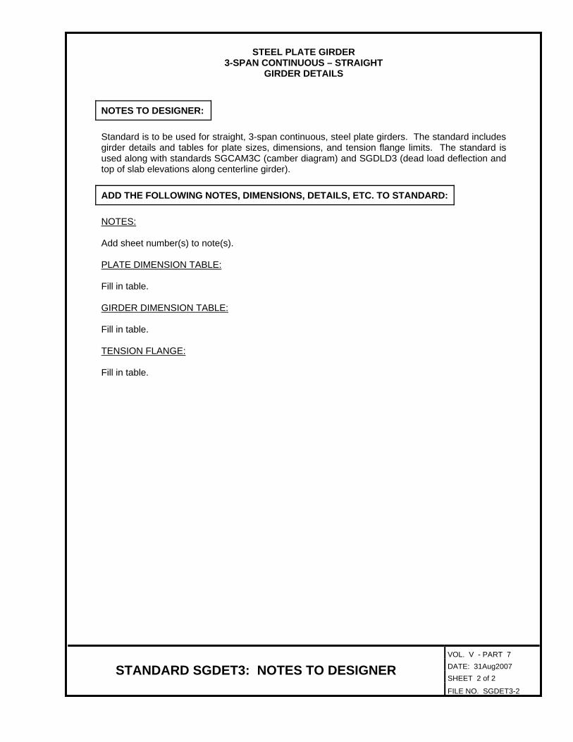
3-SPAN CONTINUOUS – STRAIGHT GIRDER DETAILS
NOTES TO DESIGNER:
Standard is to be used for straight, 3-span continuous, steel plate girders. The standard includes girder details and tables for plate sizes, dimensions, and tension flange limits. The standard is used along with standards SGCAM3C (camber diagram) and SGDLD3 (dead load deflection and top of slab elevations along centerline girder).
ADD THE FOLLOWING NOTES, DIMENSIONS, DETAILS, ETC. TO STANDARD:
NOTES: Add sheet number(s) to note(s).
PLATE DIMENSION TABLE: Fill in table.
GIRDER DIMENSION TABLE: Fill in table.
TENSION FLANGE:
Fill in table.

CAMBER
s
’s
c
H
Total
Girder
H
Total
H
Total
H
Total
H
Total
H
Total
Girder
Girder
Girder
Girder
Girder
Girder
Girders
All
CAMBER DIAGRAM
SGCAM3
c
= Deflection of girder from dead load of concrete
deck slab and bolsters.
= Deflection of girder from dead load (e.g. parapet)
added after deck slab is cast.
s= Deflection of girder from its own weight after
erection including diaphragms, connectors, etc.
top of web at any point being considered.
H = Distance between horizontal reference line and deflected
Not to scale
’s
SG
CA
M3
Midpoint
L permissible splice
MidpointMidpoint
L permissible splice
Horiz. reference line
Top of web as fabricated
Deflected top of
web without CT
s + ’s + c + H
H
at
L bearingC
CLC
at
L bearingCat
L bearingC
at
L bearingC
Tight fit to tension flange(s).
to compression flange(s).
Note A: �" fillet weld (both sides) CROSS FRAME
CONNECTOR PLATE
Detail A
Detail A
PL
1�"
�
�
1�"
TRANSVERSE INTERMEDIATE
STIFFENER
PL
Detail A
See Note A
1�"
1�"
�
-
-
DETAIL A
-
Typ. when
stiffener
is narrower
than flange
�" + �"�" + �"
�" + �" both ends
Typ. when
stiffener
is wider
than flange
-�" + �"
BEARING STIFFENERS
1" typ.
Detail A
Mill to bear
PL
Typ. when stiffener is
wider than flange
Typ. when stiffener is
narrower than flange
1�" typ.
impact requirements.
and all splice plates are areas of tensile stress for Charpy V-Notch
The top and bottom flanges as shown in Girder Elevation, the web
bolted field splice, see bolted splice details, sheet .
For spacing of stud shear connectors in vicinity of permissible
diate web stiffener PL’s, see Framing Plan, sheet .
For spacing of intermediate diaphragm connector PL’s and interme-
stiffeners by increasing the web thickness to .
The Contractor has the option of eliminating the intermediate web
Notes:
�
06-14-2010
Date Plan No. Sheet No.Designed: ...........
Drawn: ................
Checked: ............2010, Commonwealth of Virginiac
No. Description Date
STRUCTURE AND BRIDGE DIVISION
COMMONWEALTH OF VIRGINIA
DEPARTMENT OF TRANSPORTATION
Revisions
ROUTE
FEDERAL AID
PROJECT ROUTE PROJECT
STATE SHEET
NO.
VA.
STATEROUTE
FEDERAL AID
PROJECT ROUTE PROJECT
STATE SHEET
NO.
VA.
STATE
STRUCTURAL ENGINEER
RICHMOND, VA
VDOT S&B DIVISION
sgca
m3.d
gn
VOL. V - PART 7 DATE: 29May2009 SHEET 2 of 2
STANDARD SGCAM3: NOTES TO DESIGNER FILE NO. SGCAM3-2
STEEL PLATE GIRDER
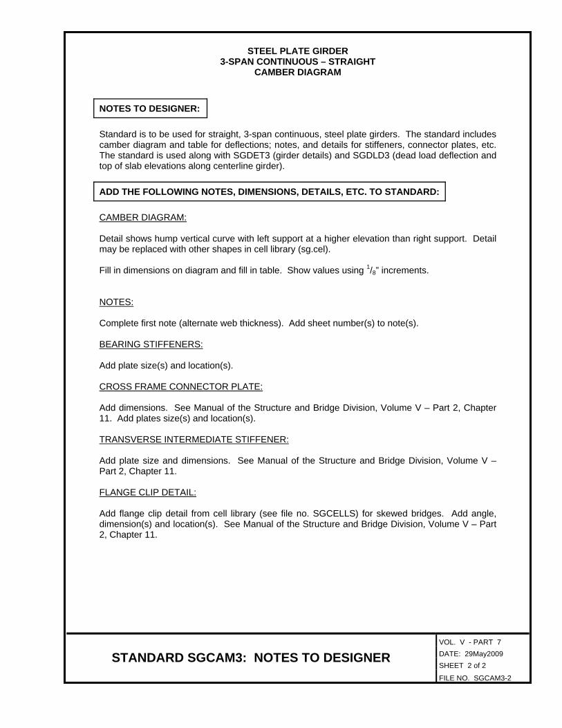
3-SPAN CONTINUOUS – STRAIGHT CAMBER DIAGRAM
NOTES TO DESIGNER:
Standard is to be used for straight, 3-span continuous, steel plate girders. The standard includes camber diagram and table for deflections; notes, and details for stiffeners, connector plates, etc. The standard is used along with SGDET3 (girder details) and SGDLD3 (dead load deflection and top of slab elevations along centerline girder).
ADD THE FOLLOWING NOTES, DIMENSIONS, DETAILS, ETC. TO STANDARD: CAMBER DIAGRAM:
Detail shows hump vertical curve with left support at a higher elevation than right support. Detail may be replaced with other shapes in cell library (sg.cel).
Fill in dimensions on diagram and fill in table. Show values using 1/8” increments. NOTES: Complete first note (alternate web thickness). Add sheet number(s) to note(s).
BEARING STIFFENERS: Add plate size(s) and location(s).
CROSS FRAME CONNECTOR PLATE: Add dimensions. See Manual of the Structure and Bridge Division, Volume V – Part 2, Chapter 11. Add plates size(s) and location(s).
TRANSVERSE INTERMEDIATE STIFFENER: Add plate size and dimensions. See Manual of the Structure and Bridge Division, Volume V – Part 2, Chapter 11.
FLANGE CLIP DETAIL: Add flange clip detail from cell library (see file no. SGCELLS) for skewed bridges. Add angle, dimension(s) and location(s). See Manual of the Structure and Bridge Division, Volume V – Part 2, Chapter 11.

DEAD LOAD DEFLECTIONS
10 11 12 13 14 15 16 17 18 19 20 21 22 23 24 25 26 27 28 29 30Point
Girder
Girder
Girder
Girder
Girder
Girder
TOP OF SLAB ELEVATIONS ALONG L GIRDERC
31 32 33 34 35 36 37 38 39 40
Finished grade after
full dead load deflection
Top of web after full
dead load deflection
Top of web after
deflection from
steel dead load only
10 11 12 13 14 15 16 17 18 19 20
10 equal spaces
21 22 23 24 25 26 27 28 29 30
10 equal spaces
393837363534333231
10 equal spaces
40
10 11 12 13 14 15 16 17 18 19 20 21 22 23 24 25 26 27 28 29 30Point
Total
Gir
der
31 32 33 34 35 36 37 38 39 40
SGDLD3
C
All values in Dead Load Deflection Table are in inches.
c
= Deflection of girder from dead load of concrete
deck slab and bolsters.
= Deflection of girder from dead load (e.g. parapet)
added after deck slab is cast.
’s
Not to scale
SG
DL
D3
at
L bearingC
at
L bearingC
at
L bearingC
at
L bearing
AND SLAB ELEVATIONS
DEAD LOAD DEFLECTIONS
’s
c
06-14-2010
Date Plan No. Sheet No.Designed: ...........
Drawn: ................
Checked: ............2010, Commonwealth of Virginiac
No. Description Date
STRUCTURE AND BRIDGE DIVISION
COMMONWEALTH OF VIRGINIA
DEPARTMENT OF TRANSPORTATION
Revisions
ROUTE
FEDERAL AID
PROJECT ROUTE PROJECT
STATE SHEET
NO.
VA.
STATEROUTE
FEDERAL AID
PROJECT ROUTE PROJECT
STATE SHEET
NO.
VA.
STATE
STRUCTURAL ENGINEER
RICHMOND, VA
VDOT S&B DIVISION
sgdld
3.d
gn
VOL. V - PART 7 DATE: 29May2009 SHEET 2 of 2
STANDARD SGDLD3: NOTES TO DESIGNER FILE NO. SGDLD3-2
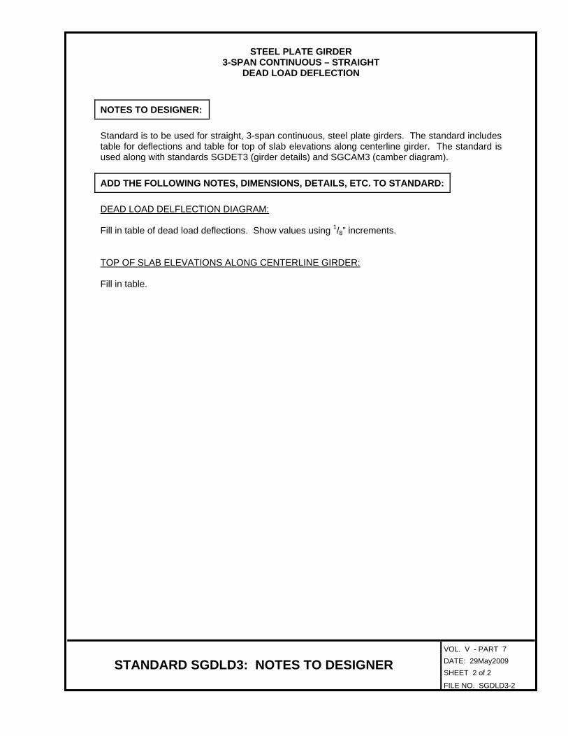
STEEL PLATE GIRDER
3-SPAN CONTINUOUS – STRAIGHT DEAD LOAD DEFLECTION
NOTES TO DESIGNER:
Standard is to be used for straight, 3-span continuous, steel plate girders. The standard includes table for deflections and table for top of slab elevations along centerline girder. The standard is used along with standards SGDET3 (girder details) and SGCAM3 (camber diagram).
ADD THE FOLLOWING NOTES, DIMENSIONS, DETAILS, ETC. TO STANDARD:
DEAD LOAD DELFLECTION DIAGRAM: Fill in table of dead load deflections. Show values using 1/8” increments.
TOP OF SLAB ELEVATIONS ALONG CENTERLINE GIRDER: Fill in table.

PLATE DIMENSION TABLE
GIRDER DIMENSION TABLE
Girder Web PL PL 1 PL 2 PL 3 PL 4 PL 5 PL 6 PL 7 PL 8 PL 9
Girder ATAB BTBB CTCB DTDB ETEB FTFB GTGB HTHB ITIB JTJB KTKB LTLB MTMB NTNB
PL 10 PL 11 PL 12 PL 13 PL 14 PL 15 PL 16 PL 17 PL 18 PL 19 PL 20 PL 21 PL 22 PL 23 PL 24 PL 25 PL 26
OTOB PA PB
GIRDER DIMENSION TABLE
PC PD PE PF PG QC QD QE QF QGGirder
PL 1
L bearing
Web PL
PA
AB CB DB
QA
PL 5
�
GIRDER ELEVATION
T2 T3
Tension flange topTension flange top
T1
Tension flange bottom
PL 3
BB
PL 2
PB
Typ.
PL 4
OT
QX
T7T6
Tension flange top Tension flange top
T8
PD
PL 6
AT BT CT DT ET FT GT
PL 7 PL 8 PL 9PL 13PL 12
PL 11PL 10
HT IT JT KT LT MT NT
OBNBMBLB
PL 26
Sec. 407.04 typ.
VDOT Specs.
PL 25PL 24PL 23
T4T5
Tension flange bottom
PC
HBEB FB GB IB JB KB
PE
PL 22PL 21PL 20PL 19
PL 18PL 17
PL 15PL 16
PL 14
with reinforcing steel.
nectors per row. Align
3 - �" o stud shear con-
L bearing
= 3’-0" = 3’-0"
GIRDER DETAILS
SGDET3C
SG
DE
T3
C
Not to scale
QU QW QXGirder
PH PI QA QB QH QI QJ QK QL QM QN QO QP QQ QR QS QT
RadiusQV
GIRDER DIMENSION TABLE TENSION FLANGES
T1 T2 T3 T4 T5 T6 T7 T8Girder
6 spa. @ 6" 6 spa. @ 6"
/
PF PG
bolted field splice
L permissible
bolted field splice
L permissible
PH PI
CC
= QC
QB equal spa. QD equal spa.
= QE
QG equal spa.
= QH
QF QKQI equal spa.
= QJQL equal spa. = QM
QN QSQO equal spa.
= QP
QQ equal spa.
= QR
QT equal spa. QV equal spa.
= QU = QW
C
Symbol o = diameter.
For notes and details, see sheet .
/
C
CC
L bearing and L pier L bearing and L pierCC C C
Tension flange bottom
Face of backwall at
abutment or L pier
Face of backwall at
abutment or L pier
06-14-2010
Date Plan No. Sheet No.Designed: ...........
Drawn: ................
Checked: ............2010, Commonwealth of Virginiac
No. Description Date
STRUCTURE AND BRIDGE DIVISION
COMMONWEALTH OF VIRGINIA
DEPARTMENT OF TRANSPORTATION
Revisions
ROUTE
FEDERAL AID
PROJECT ROUTE PROJECT
STATE SHEET
NO.
VA.
STATEROUTE
FEDERAL AID
PROJECT ROUTE PROJECT
STATE SHEET
NO.
VA.
STATE
STRUCTURAL ENGINEER
RICHMOND, VA
VDOT S&B DIVISION
sgdet3c.d
gn

VOL. V - PART 7 DATE: 31Aug2007 SHEET 2 of 2
STANDARD SGDET3C: NOTES TO DESIGNER FILE NO. SGDET3C-2
STEEL PLATE GIRDER
3-SPAN CONTINUOUS – TRAPEZOIDAL OR CURVED GIRDER DETAILS
NOTES TO DESIGNER:
Standard is to be used for trapezoidal or curved, 3-span continuous, steel plate girders. The standard includes girder details and tables for plate sizes, dimensions, and tension flange limits. The standard is used along with standards SGCAM3C (camber diagram) and SGDLD3C (dead load deflection and top of slab elevations along centerline girder).
ADD THE FOLLOWING NOTES, DIMENSIONS, DETAILS, ETC. TO STANDARD:
NOTES: Add sheet number(s) to note(s).
PLATE DIMENSION TABLE: Fill in table.
GIRDER DIMENSION TABLE: Fill in table.
TENSION FLANGE:
Fill in table.
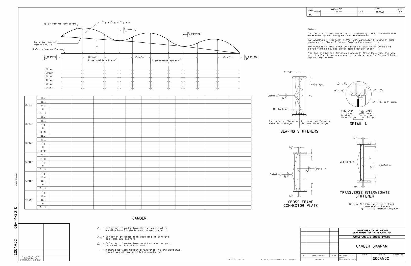
CAMBER
s
’s
c
H
Total
Girder
s
’s
c
H
Total
s
’s
c
H
Total
s
’s
c
H
Total
s
’s
c
H
Total
s
’s
c
H
Total
Girder
Girder
Girder
Girder
Girder
Girder
Girder
Girder
Girder
Girder
Girder
CAMBER DIAGRAM
SGCAM3C
c
= Deflection of girder from dead load of concrete
deck slab and bolsters.
= Deflection of girder from dead load (e.g. parapet)
added after deck slab is cast.
s= Deflection of girder from its own weight after
erection including diaphragms, connectors, etc.
top of web at any point being considered.
H = Distance between horizontal reference line and deflected
Not to scale
SG
CA
M3
C
’s
Midpoint
L permissible splice
MidpointMidpoint
L permissible splice
Horiz. reference line
Top of web as fabricated
Deflected top of
web without CT
s + ’s + c + H
at
L bearingC
at
L bearingC
at
L bearingC
CCat
L bearingC
H
impact requirements.
and all splice plates are areas of tensile stress for Charpy V-Notch
The top and bottom flanges as shown in Girder Elevation, the web
bolted field splice, see bolted splice details, sheet .
For spacing of stud shear connectors in vicinity of permissible
diate web stiffener PL’s, see Framing Plan, sheet .
For spacing of intermediate diaphragm connector PL’s and interme-
stiffeners by increasing the web thickness to .
The Contractor has the option of eliminating the intermediate web
Notes:
Tight fit to tension flange(s).
to compression flange(s).
Note A: �" fillet weld (both sides) CROSS FRAME
CONNECTOR PLATE
Detail A
Detail A
PL
1�"
�
�
1�"
TRANSVERSE INTERMEDIATE
STIFFENER
PL
Detail A
See Note A
1�"
1�"
�
-
-
DETAIL A
-
Typ. when
stiffener
is narrower
than flange
�" + �"�" + �"
�" + �" both ends
Typ. when
stiffener
is wider
than flange
-�" + �"
BEARING STIFFENERS
1" typ.
Detail A
Mill to bear
PL
Typ. when stiffener is
wider than flange
Typ. when stiffener is
narrower than flange
1�" typ.
�
06-14-2010
Date Plan No. Sheet No.Designed: ...........
Drawn: ................
Checked: ............2010, Commonwealth of Virginiac
No. Description Date
STRUCTURE AND BRIDGE DIVISION
COMMONWEALTH OF VIRGINIA
DEPARTMENT OF TRANSPORTATION
Revisions
ROUTE
FEDERAL AID
PROJECT ROUTE PROJECT
STATE SHEET
NO.
VA.
STATEROUTE
FEDERAL AID
PROJECT ROUTE PROJECT
STATE SHEET
NO.
VA.
STATE
STRUCTURAL ENGINEER
RICHMOND, VA
VDOT S&B DIVISION
sgca
m3c.d
gn

VOL. V - PART 7 DATE: 29May2009 SHEET 2 of 2
STANDARD SGCAM3C: NOTES TO DESIGNER FILE NO. SGCAM3C-2
STEEL PLATE GIRDER
3-SPAN CONTINUOUS – TRAPEZOIDAL OR CURVED CAMBER DIAGRAM
NOTES TO DESIGNER:
Standard is to be used for trapezoidal or curved, 3-span continuous, steel plate girders. The standard includes camber diagram and table for deflections; notes, and details for stiffeners, connector plates, etc. The standard is used along with SGDET3C (girder details) and SGDLD3C (dead load deflection and top of slab elevations along centerline girder).
ADD THE FOLLOWING NOTES, DIMENSIONS, DETAILS, ETC. TO STANDARD:
CAMBER DIAGRAM:
Detail shows hump vertical curve with left support at a higher elevation than right support. Detail may be replaced with other shapes in cell library (sg.cel).
Fill in dimensions on diagram and fill in table. Show values using 1/8” increments. NOTES: Complete first note (alternate web thickness). Add sheet number(s) to note(s).
BEARING STIFFENERS: Add plate size(s) and location(s).
CROSS FRAME CONNECTOR PLATE: Add dimensions. See Manual of the Structure and Bridge Division, Volume V – Part 2, Chapter 11. Add plates size(s) and location(s).
TRANSVERSE INTERMEDIATE STIFFENER: Add plate size and dimensions. See Manual of the Structure and Bridge Division, Volume V – Part 2, Chapter 11.
FLANGE CLIP DETAIL:
Add flange clip detail from cell library (see file no. SGCELLS) for skewed bridges. Add angle, dimension(s) and location(s). Details may have to be moved to place cell. See Manual of the Structure and Bridge Division, Volume V – Part 2, Chapter 11.

Top of web after
deflection from
steel dead load only
10 11 12 13 14 15 16 17 18 19 20
10 equal spaces
10 11 12 13 14 15 16 17 18 19 20
21 22 23 24 25 26 27 28 29 30
21 22 23 24 25 26 27 28 29 30
10 equal spaces
Point
Total
DEAD LOAD DEFLECTIONS
10 11 12 13 14 15 16 17 18 19 20 21 22 23 24 25 26 27 28 29 30Point
Girder
Girder
Girder
Girder
Girder
Girder
TOP OF SLAB ELEVATIONS ALONG L GIRDERC
Total
Total
Total
Total
Total
Gir
der
Gir
der
Gir
der
Gir
der
Gir
der
Gir
der
393837363534333231
10 equal spaces
31 32 33 34 35 36 37 38 39 40
31 32 33 34 35 36 37 38 39 40
40
DEAD LOAD DEFLECTIONS
AND SLAB ELEVATIONS
SGDLD3C
All values in Dead Load Deflection Table are in inches.
c
= Deflection of girder from dead load of concrete
deck slab and bolsters.
= Deflection of girder from dead load (e.g. parapet)
added after deck slab is cast.
Not to scale
SG
DL
D3
C
full dead load deflection
Finished grade after
at
L bearingC
dead load deflection
Top of web after full
at
L bearingC
at
L bearingat
L bearingCC
’s
’s
c
’s
c
’s
c
’s
c
’s
c
’s
c
06-14-2010
Date Plan No. Sheet No.Designed: ...........
Drawn: ................
Checked: ............2010, Commonwealth of Virginiac
No. Description Date
STRUCTURE AND BRIDGE DIVISION
COMMONWEALTH OF VIRGINIA
DEPARTMENT OF TRANSPORTATION
Revisions
ROUTE
FEDERAL AID
PROJECT ROUTE PROJECT
STATE SHEET
NO.
VA.
STATEROUTE
FEDERAL AID
PROJECT ROUTE PROJECT
STATE SHEET
NO.
VA.
STATE
STRUCTURAL ENGINEER
RICHMOND, VA
VDOT S&B DIVISION
sgdld
3c.d
gn

VOL. V - PART 7 DATE: 29May2009 SHEET 2 of 2
STANDARD SGDLD3C: NOTES TO DESIGNER FILE NO. SGDLD3C-2
STEEL PLATE GIRDER
3-SPAN CONTINUOUS – TRAPEZOIDAL OR CURVED DEAD LOAD DEFLECTION
NOTES TO DESIGNER:
Standard is to be used for trapezoidal or curved, 3-span continuous, steel plate girders. The standard includes table for deflections and table for top of slab elevations along centerline girder. The standard is used along with standards SGDET3C (girder details) and SGCAM3C (camber diagram).
ADD THE FOLLOWING NOTES, DIMENSIONS, DETAILS, ETC. TO STANDARD:
DEAD LOAD DELFLECTION DIAGRAM: Fill in table of dead load deflections. Show values using 1/8” increments.
TOP OF SLAB ELEVATIONS ALONG CENTERLINE GIRDER: Fill in table.

PL 1
L bearing
Web PL
WA
AB CB DB
XA
PL 5
�
GIRDER ELEVATION
T2 T3
T1
Tension flange bottom
PL 3
BB
PL 2
WB
Typ.
PL 4
T6
PL 6
AT BT CT DT ET FT GT
PL 7PL 8 PL 9
HT IT JT KT
Sec. 407.04 typ.
VDOT Specs.
T4T5
Tension flange bottom
WC
HBEB FB GB IB JB KB
PL 28PL 27
PL 26PL 25PL 24
PL 23PL 21 PL 22
PL 20
with reinforcing steel.
nectors per row. Align
3 - �" o stud shear con-/
PL 29
see sheet
Match line -
= XP = 3’-0"
PLATE DIMENSION TABLE
GIRDER DIMENSION TABLE
Girder Web PL PL 1 PL 2 PL 3 PL 4 PL 5 PL 6 PL 7 PL 8 PL 9 PL28
Girder ATAB BTBB CTCB DTDB ETEB FTFB GTGB HTHB ITIB JTJB KTKB
TENSION FLANGES
T1 T2 T3 T4 T5 T6
PL 20 PL 21 PL 22 PL 23 PL 24 PL 25 PL 26 PL 27 PL 29PL 10
GIRDER DETAILS
SGDET4A
SG
DE
T4
A
Girder
Not to scale
L bearing and L pierC C
WEWD
6 spa. @ 6" XB equal spa.
= XC
XD equal spa.
= XE
XF XG equal spa. XI equal spa.
= XH = XJ
XKXL equal spa. = XM
XN XO equal spa.
Tension flange top Tension flange top Tension flange top
bolted field splice
L permissiblebolted field splice
L permissibleC C
GIRDER DIMENSION TABLE
Girder WBWA WDWC WFWE XBXA XDXC XE XHXG XJXI XNXM XOXF XK XL XP
C
WF
C
Face of backwall at
abutment or L pier
L bearing
and L pier
C
C
/
PL 10
Radius
Symbol o = diameter.
impact requirements.
and all splice plates are areas of tensile stress for Charpy V-Notch
The top and bottom flanges as shown in Girder Elevation, the web
bolted field splice, see bolted splice details, sheet .
For spacing of stud shear connectors in vicinity of permissible
diate web stiffener PL’s, see Framing Plan, sheet .
For spacing of intermediate diaphragm connector PL’s and interme-
stiffeners by increasing the web thickness to .
The Contractor has the option of eliminating the intermediate web
Notes:
Tight fit to tension flange(s).
to compression flange(s).
Note A: �" fillet weld (both sides)
TRANSVERSE INTERMEDIATE
STIFFENER
PL
Detail A
See Note A
1�"
1�"
�
CROSS FRAME
CONNECTOR PLATE
Detail A
Detail A
PL
1�"
�
�
1�"
-
-
DETAIL A
-
Typ. when
stiffener
is narrower
than flange
�" + �"�" + �"
�" + �" both ends
Typ. when
stiffener
is wider
than flange
-�" + �"
BEARING STIFFENERS
1" typ.
Detail A
Mill to bear
PL
Typ. when stiffener is
wider than flange
Typ. when stiffener is
narrower than flange
1�" typ.
�
06-14-2010
Date Plan No. Sheet No.Designed: ...........
Drawn: ................
Checked: ............2010, Commonwealth of Virginiac
No. Description Date
STRUCTURE AND BRIDGE DIVISION
COMMONWEALTH OF VIRGINIA
DEPARTMENT OF TRANSPORTATION
Revisions
ROUTE
FEDERAL AID
PROJECT ROUTE PROJECT
STATE SHEET
NO.
VA.
STATEROUTE
FEDERAL AID
PROJECT ROUTE PROJECT
STATE SHEET
NO.
VA.
STATE
STRUCTURAL ENGINEER
RICHMOND, VA
VDOT S&B DIVISION
sgdet4a.d
gn
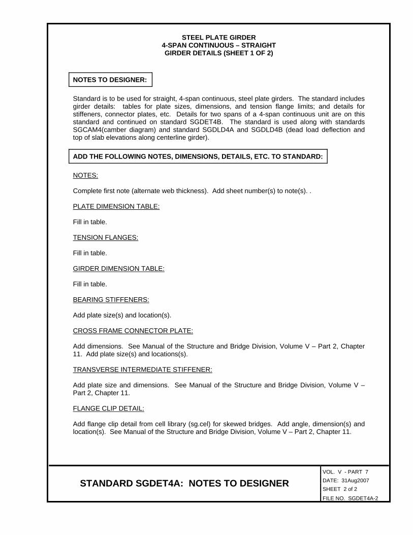
VOL. V - PART 7 DATE: 31Aug2007 SHEET 2 of 2
STANDARD SGDET4A: NOTES TO DESIGNER FILE NO. SGDET4A-2
STEEL PLATE GIRDER
4-SPAN CONTINUOUS – STRAIGHT GIRDER DETAILS (SHEET 1 OF 2)
NOTES TO DESIGNER:
Standard is to be used for straight, 4-span continuous, steel plate girders. The standard includes girder details: tables for plate sizes, dimensions, and tension flange limits; and details for stiffeners, connector plates, etc. Details for two spans of a 4-span continuous unit are on this standard and continued on standard SGDET4B. The standard is used along with standards SGCAM4(camber diagram) and standard SGDLD4A and SGDLD4B (dead load deflection and top of slab elevations along centerline girder).
ADD THE FOLLOWING NOTES, DIMENSIONS, DETAILS, ETC. TO STANDARD:
NOTES: Complete first note (alternate web thickness). Add sheet number(s) to note(s). .
PLATE DIMENSION TABLE: Fill in table.
TENSION FLANGES:
Fill in table.
GIRDER DIMENSION TABLE:
Fill in table.
BEARING STIFFENERS: Add plate size(s) and location(s).
CROSS FRAME CONNECTOR PLATE: Add dimensions. See Manual of the Structure and Bridge Division, Volume V – Part 2, Chapter 11. Add plate size(s) and locations(s).
TRANSVERSE INTERMEDIATE STIFFENER: Add plate size and dimensions. See Manual of the Structure and Bridge Division, Volume V – Part 2, Chapter 11.
FLANGE CLIP DETAIL: Add flange clip detail from cell library (sg.cel) for skewed bridges. Add angle, dimension(s) and location(s). See Manual of the Structure and Bridge Division, Volume V – Part 2, Chapter 11.

GIRDER DIMENSION TABLE
PLATE DIMENSION TABLE
GIRDER DIMENSION TABLE
L bearing
Web PL
WI
VBTBSB
X7
�
GIRDER ELEVATION
Tension flange top Tension flange top
Tension flange bottom
UB
WH
Typ.
T7
Tension flange top
UTTTSTRTQTPT
Girder Web PL
Girder LTLB MTMB NTNB OT PTPB QTQB RTRB STSB TTTB UTUB VTVB
TENSION FLANGES
PL 10
OTNTMTLT
T7 T8 T9
Girder WG WI WJ WK WL XQ XR XS XT XU
T9T8
Tension flange bottom
WG
OB RBQBPBNBMBLB
PL 31PL 32
PL 33 PL 34 PL 35PL 37PL 36
PL 38
nectors per row. Align
with reinforcing steel.
/
PL 29
= XR
PL 29 PL 30 PL 31 PL 32 PL 33 PL 34 PL 35 PL 36 PL 38PL 19
PL 11 PL 12
T12
PL 18PL 17PL 16
T11T10
PL 15PL 14PL 13
3 - �" o stud shear con-
T10 T11 T12
WH XW
PL 10 PL 11 PL 12 PL 13 PL 14 PL 15 PL 16 PL 17 PL 18 PL 37
GIRDER DETAILS
SGDET4B
SG
DE
T4
B
Girder
Not to scale
XV XX XY XZ X2 X3 X4 X5 X6 X7 Radius
XQ equal spa. XSXT equal spa. = XU
XV XW equal spa.
= XX
XY equal spa.
= XZ
X2 X3 equal spa.
= X4
X5 equal spa.
= X6 = 3’-0"
bolted field splice
L permissibleCbolted field splice
L permissibleC
L bearing and L pierCC
WJ WK WL
C
C
CSec. 407.04 typ.
VDOT Specs.
C
/
OB
6 spa. @ 6"
VT
PL 19
see sheet
Match line -
Symbol o = diameter.
For notes and details, see sheet .
Notes:
Face of backwall at
abutment or L pier
L bearing
and L pier
PL 30
06-14-2010
Date Plan No. Sheet No.Designed: ...........
Drawn: ................
Checked: ............2010, Commonwealth of Virginiac
No. Description Date
STRUCTURE AND BRIDGE DIVISION
COMMONWEALTH OF VIRGINIA
DEPARTMENT OF TRANSPORTATION
Revisions
ROUTE
FEDERAL AID
PROJECT ROUTE PROJECT
STATE SHEET
NO.
VA.
STATEROUTE
FEDERAL AID
PROJECT ROUTE PROJECT
STATE SHEET
NO.
VA.
STATE
STRUCTURAL ENGINEER
RICHMOND, VA
VDOT S&B DIVISION
sgdet4b.d
gn
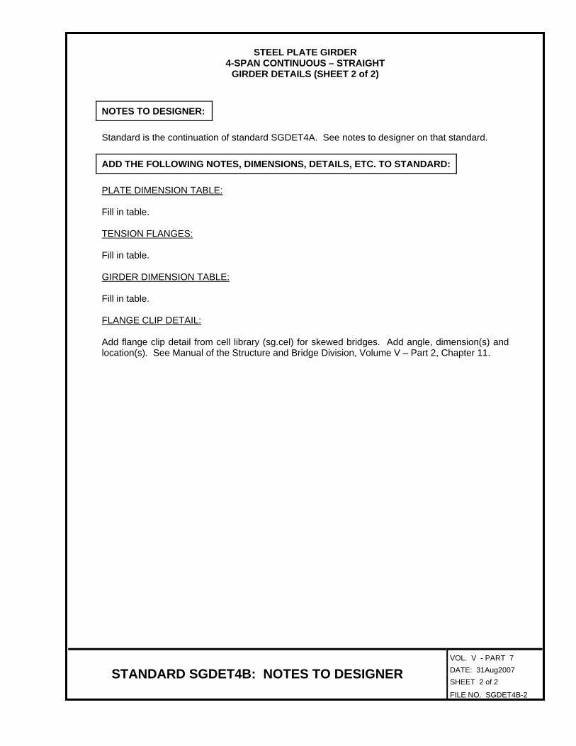
VOL. V - PART 7 DATE: 31Aug2007 SHEET 2 of 2
STANDARD SGDET4B: NOTES TO DESIGNER FILE NO. SGDET4B-2
STEEL PLATE GIRDER
4-SPAN CONTINUOUS – STRAIGHT GIRDER DETAILS (SHEET 2 of 2)
NOTES TO DESIGNER:
Standard is the continuation of standard SGDET4A. See notes to designer on that standard.
ADD THE FOLLOWING NOTES, DIMENSIONS, DETAILS, ETC. TO STANDARD:
PLATE DIMENSION TABLE:
Fill in table.
TENSION FLANGES:
Fill in table. GIRDER DIMENSION TABLE: Fill in table.
FLANGE CLIP DETAIL:
Add flange clip detail from cell library (sg.cel) for skewed bridges. Add angle, dimension(s) and location(s). See Manual of the Structure and Bridge Division, Volume V – Part 2, Chapter 11.

CAMBER
Girder
s
’s
c
H
TOTAL
H
TOTAL
H
TOTAL
H
TOTAL
H
TOTAL
H
TOTAL
Girders
All
Girder
Girder
Girder
Girder
Girder
Girder
CAMBER DIAGRAM
SGCAM4
c
= Deflection of girder from dead load of concrete
deck slab and bolsters.
= Deflection of girder from dead load (e.g. parapet)
added after deck slab is cast.
’s
s = Deflection of girder from its own weight after
erection including diaphragms, connectors, etc.
top of web at any point being considered.
H = Distance between horizontal reference line and deflected
Not to scale
SG
CA
M4
MidpointMidpointMidpointMidpoint
L permissible splice
Horiz. reference line
Top of web as fabricated
Deflected top of
web without CT
L permissible splice L permissible splice
s + ’s + c + H
at
L bearingC
C
at
L bearingC
C C
at
L bearingC
at
L bearingC
H
at
L bearingC
06-14-2010
Date Plan No. Sheet No.Designed: ...........
Drawn: ................
Checked: ............2010, Commonwealth of Virginiac
No. Description Date
STRUCTURE AND BRIDGE DIVISION
COMMONWEALTH OF VIRGINIA
DEPARTMENT OF TRANSPORTATION
Revisions
ROUTE
FEDERAL AID
PROJECT ROUTE PROJECT
STATE SHEET
NO.
VA.
STATEROUTE
FEDERAL AID
PROJECT ROUTE PROJECT
STATE SHEET
NO.
VA.
STATE
STRUCTURAL ENGINEER
RICHMOND, VA
VDOT S&B DIVISION
sgca
m4.d
gn

VOL. V - PART 7 DATE: 29May2009 SHEET 2 of 2
STANDARD SGCAM4: NOTES TO DESIGNER FILE NO. SGCAM4-2
STEEL PLATE GIRDER
4-SPAN CONTINUOUS – STRAIGHT CAMBER DIAGRAM
NOTES TO DESIGNER:
Standard is to be used for straight, 4-span continuous, steel plate girders. The standard includes camber diagram and table for deflections. The standard is used along with standards SGDET4A and SGDET4B (girder details; tables for plate sizes, dimensions, and tension flange limits; and details for stiffeners, connector plates, etc.) and SGDLD4A and SGDLD4B (dead load deflection and top of slab elevations along centerline girder).
ADD THE FOLLOWING NOTES, DIMENSIONS, DETAILS, ETC. TO STANDARD:
CAMBER DIAGRAM: Detail shows hump vertical curve with left support at a higher elevation than right support. Detail may be replaced with other shapes in cell library (sg.cel). Fill in dimensions on diagram and fill in table. Show values using 1/8” increments.
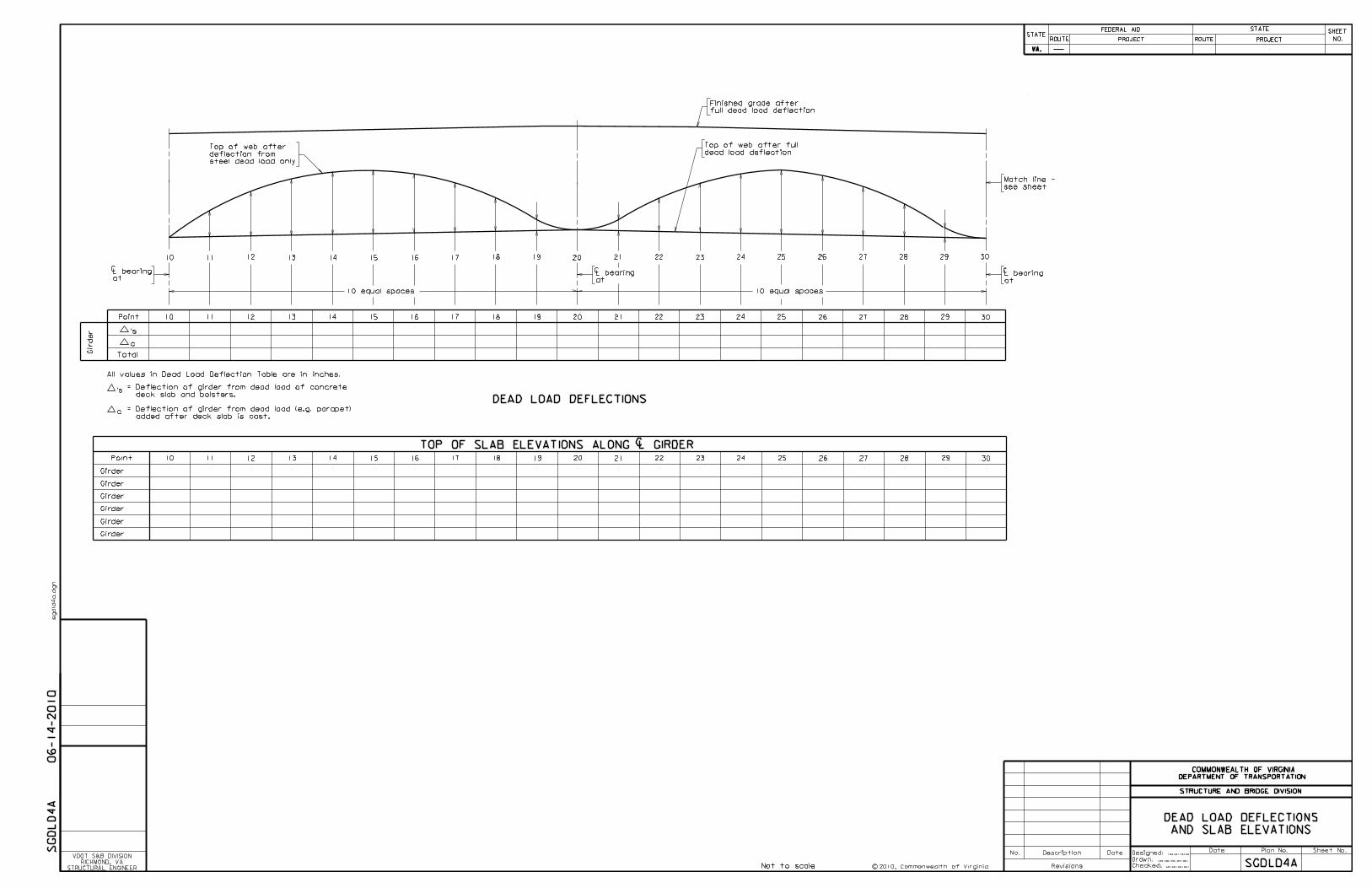
Finished grade after
full dead load deflection
Top of web after full
dead load deflectionTop of web after
deflection from
steel dead load only
10 11 12 13 14 15 16 17 18 19 20
10 equal spaces
10 11 12 13 14 15 16 17 18 19 20
21 22 23 24 25 26 27 28 29 30
21 22 23 24 25 26 27 28 29 30
10 equal spaces
Point
Total
DEAD LOAD DEFLECTIONS
10 11 12 13 14 15 16 17 18 19 20 21 22 23 24 25 26 27 28 29 30Point
Girder
Girder
Girder
Girder
Girder
Girder
TOP OF SLAB ELEVATIONS ALONG L GIRDERC
Gir
der
see sheet
Match line -
DEAD LOAD DEFLECTIONS
AND SLAB ELEVATIONS
SGDLD4ANot to scale
SG
DL
D4
A
at
L bearingC
at
L bearingC
at
L bearingC
All values in Dead Load Deflection Table are in inches.
c
= Deflection of girder from dead load of concrete
deck slab and bolsters.
= Deflection of girder from dead load (e.g. parapet)
added after deck slab is cast.
’s
’s
c
06-14-2010
Date Plan No. Sheet No.Designed: ...........
Drawn: ................
Checked: ............2010, Commonwealth of Virginiac
No. Description Date
STRUCTURE AND BRIDGE DIVISION
COMMONWEALTH OF VIRGINIA
DEPARTMENT OF TRANSPORTATION
Revisions
ROUTE
FEDERAL AID
PROJECT ROUTE PROJECT
STATE SHEET
NO.
VA.
STATEROUTE
FEDERAL AID
PROJECT ROUTE PROJECT
STATE SHEET
NO.
VA.
STATE
STRUCTURAL ENGINEER
RICHMOND, VA
VDOT S&B DIVISION
sgdld
4a.d
gn

VOL. V - PART 7 DATE: 29May2009 SHEET 2 of 2
STANDARD SGDLD4A: NOTES TO DESIGNER FILE NO. SGDLD4A-2
STEEL PLATE GIRDER
4-SPAN CONTINUOUS – STRAIGHT DEAD LOAD DEFLECTION (SHEET 1 OF 2)
NOTES TO DESIGNER: Standard is to be used for straight, 4-span continuous, steel plate girders. The standard includes table for deflections and top of slab elevations along centerline girder for the first two spans of a 4-span continuous unit and is continued on standard SGDLD4B. The standard is used along with standards SGDET4A and SGDET4B (girder details; tables for plate sizes, dimensions, and tension flange limits; and details for stiffeners, connector plates, etc.) and standard SGCAM4 (camber diagram).
ADD THE FOLLOWING NOTES, DIMENSIONS, DETAILS, ETC. TO STANDARD:
DEAD LOAD DELFLECTION DIAGRAM:
Fill in table of dead load deflections. Show values using 1/8” increments.
TOP OF SLAB ELEVATIONS ALONG CENTERLINE GIRDER: Fill in table.

30
30 31 32 33 34 35 36 37 38 39 40
31 32 33 34 35 36 37 38 39 40
41 42 43 44 45 46 47 48 49 50
10 equal spaces
Point
Total
DEAD LOAD DEFLECTIONS
30 31 32 33 34 35 36 37 38 39 40 41 42 43 44 45 46 47 48 49 50Point
Girder
Girder
Girder
Girder
Girder
Girder
TOP OF SLAB ELEVATIONS ALONG L GIRDERC
Gir
der
494847464544433241
10 equal spaces
50
see sheet
Match line -
SGDLD4B
from steel dead load only.
Top of web after deflection
All values in Dead Load Deflection Table are in inches.
c
= Deflection of girder from dead load of concrete
deck slab and bolsters.
= Deflection of girder from dead load (e.g. parapet)
added after deck slab is cast.
’s
Not to scale
SG
DL
D4
B
full dead load deflection
Finished grade after
dead load deflection
Top of web after full
at
L bearingC
at
L bearingC
at
L bearingC
’s
c
AND SLAB ELEVATIONS
DEAD LOAD DEFLECTIONS
06-14-2010
Date Plan No. Sheet No.Designed: ...........
Drawn: ................
Checked: ............2010, Commonwealth of Virginiac
No. Description Date
STRUCTURE AND BRIDGE DIVISION
COMMONWEALTH OF VIRGINIA
DEPARTMENT OF TRANSPORTATION
Revisions
ROUTE
FEDERAL AID
PROJECT ROUTE PROJECT
STATE SHEET
NO.
VA.
STATEROUTE
FEDERAL AID
PROJECT ROUTE PROJECT
STATE SHEET
NO.
VA.
STATE
STRUCTURAL ENGINEER
RICHMOND, VA
VDOT S&B DIVISION
sgdld
4b.d
gn

VOL. V - PART 7 DATE: 31Aug2007 SHEET 2 of 2
STANDARD SGDLD4B: NOTES TO DESIGNER FILE NO. SGDLD4B-2
STEEL PLATE GIRDER
4-SPAN CONTINUOUS – STRAIGHT DEAD LOAD DEFLECTION (SHEET 2 OF 2)
NOTES TO DESIGNER: Standard is the continuation of standard SGDLD4A. See notes to designer on that standard.
ADD THE FOLLOWING NOTES, DIMENSIONS, DETAILS, ETC. TO STANDARD:
See standard SGDLD4A.

PL 1
L bearing
Web PL
WA
AB DB
XA
PL 5
�
GIRDER ELEVATION
T2 T3
Tension flange topTension flange top
T1
Tension flange bottom
PL 3
BB
PL 2
WB
Typ.
PL 4
T6
Tension flange top
PL 6
AT BT CT DT ET FT GT
PL 7PL 8 PL 9
PL 10
HT IT JT KT
XL eq. spa. = XM
Sec. 407.04 typ.
VDOT Specs.
T4T5
Tension flange bottom
WC
HBEB FB GB IB JB KB
PL 28PL 27PL 26
PL 25PL 24PL 23PL 21
PL 22PL 20
with reinforcing steel.
nectors per row. Align
3 - �" o stud shear con-/
PL 29
= XP = 3’-0"
GIRDER DIMENSION TABLE
PLATE DIMENSION TABLE
GIRDER DIMENSION TABLE
Girder Web PL PL 1 PL 2 PL 3 PL 4 PL 5 PL 6 PL 7 PL 8 PL 9 PL28
Girder ATAB BTBB CTCB DTDB ETEB FTFB GTGB HTHB ITIB JTJB KTKB
TENSION FLANGES
T1 T2 T3 T4 T5 T6
Girder WA WB WC XE
PL 20 PL 21 PL 22 PL 23 PL 24 PL 25 PL 26 PL 27 PL 29PL 10
GIRDER DETAILS
SGDET4AC
SG
DE
T4
AC
Girder
Not to scale
WD WE WF XA XB XC XD XF XG XH XL XM XN X0 XP Radius
L bearing and L pierC C
XO equal spa.6 spa. @ 6" XB equal spa.
= XC
XD equal spa.
= XE
XF XG equal spa.
= XH
XI equal spa.
= XJ
XK XN
C
WD WE
CB
bolted field splice
L permissible C
WF
bolted field splice
L permissible C
XI XJ XK
see sheet
Match line -
C
C
CL bearing
and L pier
Face of backwall at
abutment or L pier
/Symbol o = diameter.
impact requirements.
and all splice plates are areas of tensile stress for Charpy V-Notch
The top and bottom flanges as shown in Girder Elevation, the web
bolted field splice, see bolted splice details, sheet .
For spacing of stud shear connectors in vicinity of permissible
mediate web stiffener PL’s, see Framing Plan, sheet .
For spacing of intermediate diaphragm connector PL’s and inter-
stiffeners by increasing the web thickness to .
The Contractor has the option of eliminating the intermediate web
Notes:
Tight fit to tension flange(s).
to compression flange(s).
Note A: �" fillet weld (both sides)
BEARING STIFFENERS
1" typ.
Detail A
Mill to bear
PL
Typ. when stiffener is
wider than flange
Typ. when stiffener is
narrower than flange
1�" typ.
-
-
DETAIL A
-
Typ. when
stiffener
is narrower
than flange
�" + �"�" + �"
�" + �" both ends
Typ. when
stiffener
is wider
than flange
-�" + �"
TRANSVERSE INTERMEDIATE
STIFFENER
PL
Detail A
See Note A
1�"
1�"
�
CROSS FRAME
CONNECTOR PLATE
Detail A
Detail A
PL
1�"
�
�
1�"
�
06-14-2010
Date Plan No. Sheet No.Designed: ...........
Drawn: ................
Checked: ............2010, Commonwealth of Virginiac
No. Description Date
STRUCTURE AND BRIDGE DIVISION
COMMONWEALTH OF VIRGINIA
DEPARTMENT OF TRANSPORTATION
Revisions
ROUTE
FEDERAL AID
PROJECT ROUTE PROJECT
STATE SHEET
NO.
VA.
STATEROUTE
FEDERAL AID
PROJECT ROUTE PROJECT
STATE SHEET
NO.
VA.
STATE
STRUCTURAL ENGINEER
RICHMOND, VA
VDOT S&B DIVISION
sgdet4ac.d
gn

VOL. V - PART 7 DATE: 31Aug2007 SHEET 2 of 2
STANDARD SGDET4AC: NOTES TO DESIGNER FILE NO. SGDET4AC-2
STEEL PLATE GIRDER
4-SPAN CONTINUOUS – TRAPEZOIDAL OR CURVED GIRDER DETAILS (SHEET 1 OF 2)
NOTES TO DESIGNER:
Standard is to be used for trapezoidal or curved, 4-span continuous, steel plate girders. The standard includes girder details; tables for plate sizes, dimensions, and tension flange limits; and details for stiffeners, connector plates, etc. Details for two spans of a 4-span continuous unit are on this standard and continued on standard SGDET4BC. The standard is used along with standard SGCAM4 (camber diagram) and standards SGDLD4AC and SGDLD4BC (dead load deflection and top of slab elevations along centerline girder).
ADD THE FOLLOWING NOTES, DIMENSIONS, DETAILS, ETC. TO STANDARD:
NOTES: Complete first note (alternate web thickness). Add sheet number(s) to note(s).
PLATE DIMENSION TABLE: Fill in table.
TENSION FLANGES: Fill in table.
GIRDER DIMENSION TABLE:
Fill in table.
BEARING STIFFENERS: Add plate size(s) and location(s).
CROSS FRAME CONNECTOR PLATE: Add dimensions. See Manual of the Structure and Bridge Division, Volume V – Part 2, Chapter 11. Add plate size(s) and location(s).
TRANSVERSE INTERMEDIATE STIFFENER:
Add plate size and dimensions. See Manual of the Structure and Bridge Division, Volume V – Part 2, Chapter 11.
FLANGE CLIP DETAIL: Add flange clip detail from cell library (sg.cel) for skewed bridges. Add angle, dimension(s) and location(s). See Manual of the Structure and Bridge Division, Volume V – Part 2, Chapter 11.

GIRDER DIMENSION TABLE
PLATE DIMENSION TABLE
GIRDER DIMENSION TABLE
Girder Web PL
Girder LTLB MTMB NTNB OTOB PTPB QTQB RTRB STSB TTTB UTUB VTVB
TENSION FLANGES
T7 T8 T9
Girder WG WI WJ WK WL
PL 29 PL 30 PL 31 PL 32 PL 33 PL 34 PL 35 PL 36 PL 38PL 19
T10 T11 T12
WH
PL 10 PL 11 PL 12 PL 13 PL 14 PL 15 PL 16 PL 17 PL 18 PL 37
L bearing
Web PL
WI
VBTBSB
X7
�
GIRDER ELEVATION
Tension flange top Tension flange top
Tension flange bottom
UB
WH
Typ.
T7
Tension flange top
VTUTTTSTRTQTPT
PL 10
OTNTMTLT
T9T8
Tension flange bottom
WG
OB RBQBPBNBMBLB
PL 30 PL 31 PL 32PL 33 PL 34
PL 35PL 37PL 36
PL 38
nectors per row. Align
with reinforcing steel.
/= XR
PL 11 PL 12
T12
= 3’-0"
PL 19PL 18PL 17PL 16
T11
PL 15PL 14PL 13
3 - �" o stud shear con-
GIRDER DETAILS
SGDET4BC
SG
DE
T4
BC
Girder
Not to scale
L bearing and L pier
XSXQ equal spa.XT equal spa. = XU
XV XW equal spa.
= XX
XY equal spa.
= XZ
X2 X3 equal spa.
= X4
X5 equal spa.
= X6
6 spa. @ 6"
WJ WK WL
bolted field splice
L permissible
Sec. 407.04 typ.
VDOT Specs.C
C
see sheet
Match line -
PL 29
C C
C
C
XQ XR XS XT XU XV XW XX XY XZ X2 X3 X4 X5 X6 X7 Radius
Symbol o = diameter.
For notes and details, see sheet .
Notes:
/
C
C
bolted field splice
L permissible
L bearing
and L pier
Face of backwall at
abutment or L pier
T10
06-14-2010
Date Plan No. Sheet No.Designed: ...........
Drawn: ................
Checked: ............2010, Commonwealth of Virginiac
No. Description Date
STRUCTURE AND BRIDGE DIVISION
COMMONWEALTH OF VIRGINIA
DEPARTMENT OF TRANSPORTATION
Revisions
ROUTE
FEDERAL AID
PROJECT ROUTE PROJECT
STATE SHEET
NO.
VA.
STATEROUTE
FEDERAL AID
PROJECT ROUTE PROJECT
STATE SHEET
NO.
VA.
STATE
STRUCTURAL ENGINEER
RICHMOND, VA
VDOT S&B DIVISION
sgdet4bc.d
gn
VOL. V - PART 7 DATE: 31Aug2007 SHEET 2 of 2
STANDARD SGDET4BC: NOTES TO DESIGNER FILE NO. SGDET4BC-2
STEEL PLATE GIRDER
4-SPAN CONTINUOUS – TRAPEZOIDAL OR CURVED GIRDER DETAILS (SHEET 2 of 2)
NOTES TO DESIGNER:
Standard is the continuation of standard SGDET4AC. See notes to designer on that standard.
ADD THE FOLLOWING NOTES, DIMENSIONS, DETAILS, ETC. TO STANDARD:
PLATE DIMENSION TABLE:
Fill in table.
TENSION FLANGES:
Fill in table. GIRDER DIMENSION TABLE: Fill in table.
FLANGE CLIP DETAIL: Add flange clip detail from cell library (sg.cel) for skewed bridges. Add angle, dimension(s) and location(s). See Manual of the Structure and Bridge Division, Volume V – Part 2, Chapter 11.

s
’s
c
H
Total
Girder
s
’s
c
H
Total
s
’s
c
H
Total
s
’s
c
H
Total
s
’s
c
H
Total
s
’s
c
H
Total
Girder
Girder
Girder
Girder
Girder
CAMBER
Girder
Girder
Girder
Girder
Girder
Girder
CAMBER DIAGRAM
SGCAM4C
c
= Deflection of girder from dead load of concrete
deck slab and bolsters.
= Deflection of girder from dead load (e.g. parapet)
added after deck slab is cast.
’s
s= Deflection of girder from its own weight after
erection including diaphragms, connectors, etc.
top of web at any point being considered.
H = Distance between horizontal reference line and deflected
Not to scale
SG
CA
M4
C
MidpointMidpointMidpointMidpoint
L permissible splice
Horiz. reference line
Top of web as fabricated
Deflected top of
web without CT
L permissible splice L permissible splice
s + ’s + c + H
at
L bearingC
C
at
L bearingC
C C
at
L bearingC
at
L bearingC
H
at
L bearingC
06-14-2010
Date Plan No. Sheet No.Designed: ...........
Drawn: ................
Checked: ............2010, Commonwealth of Virginiac
No. Description Date
STRUCTURE AND BRIDGE DIVISION
COMMONWEALTH OF VIRGINIA
DEPARTMENT OF TRANSPORTATION
Revisions
ROUTE
FEDERAL AID
PROJECT ROUTE PROJECT
STATE SHEET
NO.
VA.
STATEROUTE
FEDERAL AID
PROJECT ROUTE PROJECT
STATE SHEET
NO.
VA.
STATE
STRUCTURAL ENGINEER
RICHMOND, VA
VDOT S&B DIVISION
sgca
m4c.d
gn

VOL. V - PART 7 DATE: 29May2009 SHEET 2 of 2
STANDARD SGCAM4C: NOTES TO DESIGNER FILE NO. SGCAM4C-2
STEEL PLATE GIRDER
4-SPAN CONTINUOUS – TRAPEZOIDAL OR CURVED CAMBER DIAGRAM
NOTES TO DESIGNER:
Standard is to be used for trapezoidal or curved, 4-span continuous, steel plate girders. The standard includes the camber diagram and table for deflections. The standard is used along with standards SGDET4AC and SGDET4BC (girder details; tables for plate sizes, dimensions, and tension flange limits; and details for stiffeners, connector plates, etc.) and SGDLD4AC and SGDLD4BC (dead load deflection and top of slab elevations along centerline girder).
ADD THE FOLLOWING NOTES, DIMENSIONS, DETAILS, ETC. TO STANDARD:
CAMBER DIAGRAM: Detail shows hump vertical curve with left support at a higher elevation than right support. Detail may be replaced with other shapes in cell library (sg.cel).
Fill in dimensions on diagram and fill in table. Show values using 1/8” increments.

Finished grade after
full dead load deflection
Top of web after full
dead load deflectionTop of web after
deflection from
steel dead load only
10 11 12 13 14 15 16 17 18 19 20
10 equal spaces
10 11 12 13 14 15 16 17 18 19 20
21 22 23 24 25 26 27 28 29 30
21 22 23 24 25 26 27 28 29 30
10 equal spaces
Point
Total
DEAD LOAD DEFLECTIONS
10 11 12 13 14 15 16 17 18 19 20 21 22 23 24 25 26 27 28 29 30Point
Girder
Girder
Girder
Girder
Girder
Girder
TOP OF SLAB ELEVATIONS ALONG L GIRDERC
Total
Total
Total
Total
Total
Gir
der
Gir
der
Gir
der
Gir
der
Gir
der
Gir
der
see sheet
Match line -
SGDLD4AC
All values in Dead Load Deflection Table are in inches.
c
= Deflection of girder from dead load of concrete
deck slab and bolsters.
= Deflection of girder from dead load (e.g. parapet)
added after deck slab is cast.
’s
Not to scale
SG
DL
D4
AC
at
L bearingC
at
L bearingC
at
L bearingC
AND SLAB ELEVATIONS
DEAD LOAD DEFLECTIONS
’s
c
’s
c
’s
c
’s
c
’s
c
’s
c
06-14-2010
Date Plan No. Sheet No.Designed: ...........
Drawn: ................
Checked: ............2010, Commonwealth of Virginiac
No. Description Date
STRUCTURE AND BRIDGE DIVISION
COMMONWEALTH OF VIRGINIA
DEPARTMENT OF TRANSPORTATION
Revisions
ROUTE
FEDERAL AID
PROJECT ROUTE PROJECT
STATE SHEET
NO.
VA.
STATEROUTE
FEDERAL AID
PROJECT ROUTE PROJECT
STATE SHEET
NO.
VA.
STATE
STRUCTURAL ENGINEER
RICHMOND, VA
VDOT S&B DIVISION
sgdld
4ac.d
gn
VOL. V - PART 7 DATE: 29May2009 SHEET 2 of 2
STANDARD SGDLD4AC: NOTES TO DESIGNER FILE NO. SGDLD4AC-2
STEEL PLATE GIRDER
4-SPAN CONTINUOUS – TRAPEZOIDAL OR CURVED DEAD LOAD DEFLECTION (SHEET 1 OF 2)
NOTES TO DESIGNER: Standard is to be used for trapezoidal or curved, 4-span continuous, steel plate girders. The standard includes table for deflections and top of slab elevations along centerline girder for the first two spans of a 4-span continuous unit and is continued on standard SGDLD4BC. The standard is used along with standards SGDET4AC and SGDET4BC (girder details; tables for plate sizes, dimensions, and tension flange limits; and details for stiffeners, connector plates, etc.) and standard SGCAM4C (camber diagram).
ADD THE FOLLOWING NOTES, DIMENSIONS, DETAILS, ETC. TO STANDARD:
DEAD LOAD DELFLECTION DIAGRAM: Fill in table of dead load deflections. Show values using 1/8” increments.
TOP OF SLAB ELEVATIONS ALONG CENTERLINE GIRDER: Fill in table.

30
30 31 32 33 34 35 36 37 38 39 40
31 32 33 34 35 36 37 38 39 40
41 42 43 44 45 46 47 48 49 50
10 equal spaces
Point
Total
DEAD LOAD DEFLECTIONS
30 31 32 33 34 35 36 37 38 39 40 41 42 43 44 45 46 47 48 49 50Point
Girder
Girder
Girder
Girder
Girder
Girder
TOP OF SLAB ELEVATIONS ALONG L GIRDERC
Total
Total
Total
Total
Total
Gir
der
Gir
der
Gir
der
Gir
der
Gir
der
Gir
der
494847464544433241
10 equal spaces
50
see sheet
Match line -
SGDLD4BC
from steel dead load only
Top of web after deflection
All values in Dead Load Deflection Table are in inches.
c
= Deflection of girder from dead load of concrete
deck slab and bolsters.
= Deflection of girder from dead load (e.g. parapet)
added after deck slab is cast.
’s
Not to scale
SG
DL
D4
BC
full dead load deflection
Finished grade after
dead load deflection
Top of web after full
at
L bearingC
at
L bearingC
at
L bearingC
AND SLAB ELEVATIONS
DEAD LOAD DEFLECTIONS
c
c
’s
’s
c
’s
c
’s
’s
c
’s
c
06-14-2010
Date Plan No. Sheet No.Designed: ...........
Drawn: ................
Checked: ............2010, Commonwealth of Virginiac
No. Description Date
STRUCTURE AND BRIDGE DIVISION
COMMONWEALTH OF VIRGINIA
DEPARTMENT OF TRANSPORTATION
Revisions
ROUTE
FEDERAL AID
PROJECT ROUTE PROJECT
STATE SHEET
NO.
VA.
STATEROUTE
FEDERAL AID
PROJECT ROUTE PROJECT
STATE SHEET
NO.
VA.
STATE
STRUCTURAL ENGINEER
RICHMOND, VA
VDOT S&B DIVISION
sgdld
4bc.d
gn

VOL. V - PART 7 DATE: 31Aug2007 SHEET 2 of 2
STANDARD SGDLD4BC: NOTES TO DESIGNER FILE NO. SGDLD4BC-2
STEEL PLATE GIRDER
4-SPAN CONTINUOUS – TRAPEZOIDAL OR CURVED DEAD LOAD DEFLECTION (SHEET 2 OF 2)
NOTES TO DESIGNER: Standard is the continuation of standard SGDLD4AC. See notes to designer on that standard.
ADD THE FOLLOWING NOTES, DIMENSIONS, DETAILS, ETC. TO STANDARD:
See standard SGDLD4AC.

VOL. V - PART 7 DATE: 31Aug2007 SHEET 1 of 1
STEEL PLATE GIRDER STANDARDS CELL LIBRARY: SG.CEL
INDEX OF CELLS FILE NO. SGCELLIND-1
STEEL PLATE GIRDER STANDARDS
CELL LIBRARY: SG.CEL
INDEX OF CELLS CELL NAME FILE NO. DATE BF22...................................SGCELLS-1 .........................................................................31Aug2007 BF42...................................SGCELLS-1 .........................................................................31Aug2007 BF44...................................SGCELLS-1 .........................................................................31Aug2007 BSTIFF...............................SGCELLS-2 .........................................................................31Aug2007 CLIPLL ...............................SGCELLS-2 .........................................................................31Aug2007 CLIPLR...............................SGCELLS-2 .........................................................................31Aug2007 CLIPRL...............................SGCELLS-3 .........................................................................31Aug2007 CLIPRR ..............................SGCELLS-3 .........................................................................31Aug2007 CONNPL ............................SGCELLS-3 .........................................................................31Aug2007 DETA..................................SGCELLS-4 .........................................................................31Aug2007 DLDGRA ............................SGCELLS-4 .........................................................................31Aug2007 DLDHUM............................SGCELLS-4 .........................................................................31Aug2007 DLDSAG ............................SGCELLS-5 .........................................................................31Aug2007 NOTEA...............................SGCELLS-5 .........................................................................31Aug2007 PPTOP5 .............................SGCELLS-5 .........................................................................31Aug2007 SGCG2L.............................SGCELLS-5 .........................................................................31Aug2007 SGCG2R ............................SGCELLS-6 .........................................................................31Aug2007 SGCG3L.............................SGCELLS-6 .........................................................................31Aug2007 SGCG3R ............................SGCELLS-6 .........................................................................31Aug2007 SGCG4L.............................SGCELLS-6 .........................................................................31Aug2007 SGCG4R ............................SGCELLS-7 .........................................................................31Aug2007 SGCH2R ............................SGCELLS-7 .........................................................................31Aug2007 SGCH3L.............................SGCELLS-7 .........................................................................31Aug2007 SGCH3R ............................SGCELLS-8 .........................................................................31Aug2007 SGCH4L.............................SGCELLS-8 .........................................................................31Aug2007 SGCH4R ............................SGCELLS-8 .........................................................................31Aug2007 SGCS2L .............................SGCELLS-8 .........................................................................31Aug2007 SGCS2R ............................SGCELLS-9 .........................................................................31Aug2007 SGCS3L .............................SGCELLS-9 .........................................................................31Aug2007 SGCS3R ............................SGCELLS-9 .........................................................................31Aug2007 SGCS4L .............................SGCELLS-9 .........................................................................31Aug2007 SGCS4R ............................SGCELLS-10 .......................................................................31Aug2007 SGLB1................................SGCELLS-10 .......................................................................31Aug2007 SGLB2................................SGCELLS-10 .......................................................................31Aug2007 SGLB3................................SGCELLS-11 .......................................................................31Aug2007 SGLB4................................SGCELLS-11 .......................................................................31Aug2007 SGNT1 ...............................SGCELLS-11 .......................................................................31Aug2007 SGNT2 ...............................SGCELLS-12 .......................................................................31Aug2007 TBL5PT ..............................SGCELLS-12 .......................................................................31Aug2007 TF22...................................SGCELLS-12 .......................................................................31Aug2007 TF42...................................SGCELLS-13 .......................................................................31Aug2007 TF44...................................SGCELLS-13 .......................................................................31Aug2007 TRSTIFF ............................SGCELLS-13 .......................................................................31Aug2007 WEB ...................................SGCELLS-14 .......................................................................31Aug2007

VOL. V - PART 7 DATE: 31Aug2007 SHEET 1 of 14
STEEL PLATE GIRDER STANDARDS CELL LIBRARY: SG.CEL
CELLS FILE NO. SGCELLS-1
CELL CELL NAME CELL DESCRIPTION BF22
Bottom flange splice with 2-2 stagger bolt pattern (approx. 0.45 of actual cell size)
BF42
Bottom flange splice with 4-2 stagger bolt pattern (approx. 0.45 of actual cell size)
BF44
Bottom flange splice with 4 uniform bolt pattern (approx. 0.45 of actual cell size)
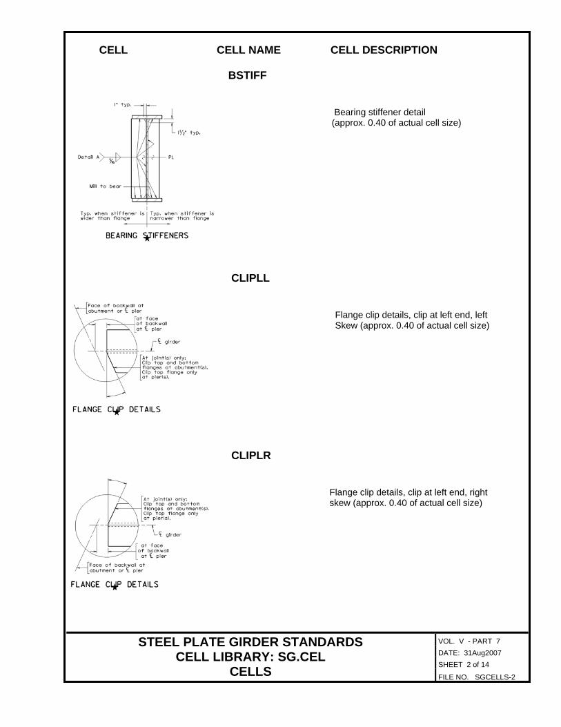
VOL. V - PART 7 DATE: 31Aug2007 SHEET 2 of 14
STEEL PLATE GIRDER STANDARDS CELL LIBRARY: SG.CEL
CELLS FILE NO. SGCELLS-2
CELL CELL NAME CELL DESCRIPTION
BSTIFF
Bearing stiffener detail (approx. 0.40 of actual cell size) CLIPLL
Flange clip details, clip at left end, left Skew (approx. 0.40 of actual cell size)
CLIPLR Flange clip details, clip at left end, right skew (approx. 0.40 of actual cell size)

VOL. V - PART 7 DATE: 31Aug2007 SHEET 3 of 14
STEEL PLATE GIRDER STANDARDS CELL LIBRARY: SG.CEL
CELLS FILE NO. SGCELLS-3
CELL CELL NAME CELL DESCRIPTION
CLIPRL
Flange clip details, clip at right end, left skew (approx. 0.40 of actual cell size)
CLIPRR
Flange clip details, clip at right end, right skew (approx. 0.40 of actual cell size)
CONNPL Cross frame connector plate detail (approx. 0.40 of actual cell size)

VOL. V - PART 7 DATE: 31Aug2007 SHEET 4 of 14
STEEL PLATE GIRDER STANDARDS CELL LIBRARY: SG.CEL
CELLS FILE NO. SGCELLS-4
CELL CELL NAME CELL DESCRIPTION
DETA Welding details for connector plates wider and narrower then the flange (approx. 0.50 of actual cell size)
DLDGRA
Deflection diagram single span gradient (approx. 0.35 of actual cell size)
DLDHUM
Deflection diagram single span hump (approx. 0.35 of actual cell size)
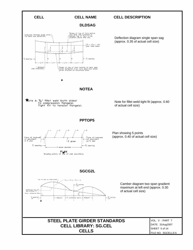
VOL. V - PART 7 DATE: 31Aug2007 SHEET 5 of 14
STEEL PLATE GIRDER STANDARDS CELL LIBRARY: SG.CEL
CELLS FILE NO. SGCELLS-5
CELL CELL NAME CELL DESCRIPTION
DLDSAG
Deflection diagram single span sag (approx. 0.35 of actual cell size)
NOTEA
Note for fillet weld tight fit (approx. 0.60 of actual cell size)
PPTOP5
Plan showing 5 points (approx. 0.40 of actual cell size)
SGCG2L
Camber diagram two span gradient maximum at left end (approx. 0.30 of actual cell size)
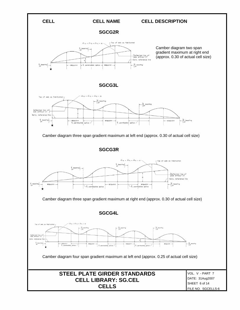
VOL. V - PART 7 DATE: 31Aug2007 SHEET 6 of 14
STEEL PLATE GIRDER STANDARDS CELL LIBRARY: SG.CEL
CELLS FILE NO. SGCELLS-6
CELL CELL NAME CELL DESCRIPTION
SGCG2R
Camber diagram two span gradient maximum at right end (approx. 0.30 of actual cell size)
SGCG3L
Camber diagram three span gradient maximum at left end (approx. 0.30 of actual cell size)
SGCG3R
Camber diagram three span gradient maximum at right end (approx. 0.30 of actual cell size)
SGCG4L
Camber diagram four span gradient maximum at left end (approx. 0.25 of actual cell size)

VOL. V - PART 7 DATE: 31Aug2007 SHEET 7 of 14
STEEL PLATE GIRDER STANDARDS CELL LIBRARY: SG.CEL
CELLS FILE NO. SGCELLS-7
CELL CELL NAME CELL DESCRIPTION
SGCG4R
Camber diagram four span gradient maximum at right end (approx. 0.25 of actual cell size)
SGCH2L
Camber diagram two span hump curve maximum at left end (approx. 0.30 of actual cell size)
SGCH2R
Camber diagram two span hump curve maximum at right end (approx. 0.30 of actual cell size)
SGCH3L
Camber diagram three span hump curve maximum at left end (approx. 0.30 of actual cell size)
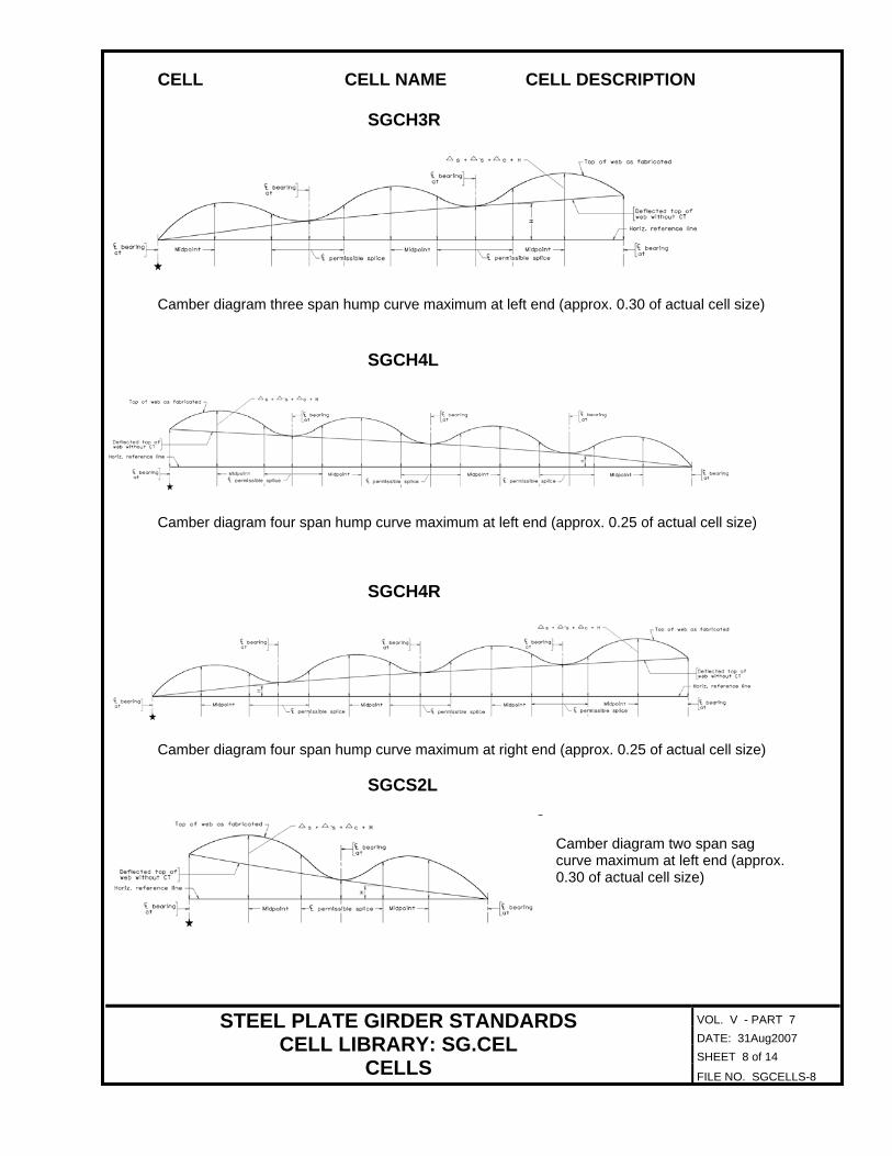
VOL. V - PART 7 DATE: 31Aug2007 SHEET 8 of 14
STEEL PLATE GIRDER STANDARDS CELL LIBRARY: SG.CEL
CELLS FILE NO. SGCELLS-8
CELL CELL NAME CELL DESCRIPTION
SGCH3R
Camber diagram three span hump curve maximum at left end (approx. 0.30 of actual cell size)
SGCH4L
Camber diagram four span hump curve maximum at left end (approx. 0.25 of actual cell size)
SGCH4R
Camber diagram four span hump curve maximum at right end (approx. 0.25 of actual cell size)
SGCS2L
Camber diagram two span sag curve maximum at left end (approx. 0.30 of actual cell size)

VOL. V - PART 7 DATE: 31Aug2007 SHEET 9 of 14
STEEL PLATE GIRDER STANDARDS CELL LIBRARY: SG.CEL
CELLS FILE NO. SGCELLS-9
CELL CELL NAME CELL DESCRIPTION
SGCS2R
Camber diagram two span sag curve maximum at right end (approx. 0.30 of actual cell size)
SGCS3L
Camber diagram three span sag curve maximum at left end (approx. 0.30 of actual cell size)
SGCS3R
Camber diagram three span sag curve maximum at left end (approx. 0.30 of actual cell size)
SGCS4L
Camber diagram four span sag curve maximum at left end (approx. 0.25 of actual cell size)

VOL. V - PART 7 DATE: 31Aug2007 SHEET 10 of 14
STEEL PLATE GIRDER STANDARDS CELL LIBRARY: SG.CEL
CELLS FILE NO. SGCELLS-10
CELL CELL NAME CELL DESCRIPTION
SGCS4R
Camber diagram four span sag curve maximum at right end (approx. 0.25 of actual cell size)
SGLB1
Lateral bracing connection detail without stiffener (approx. 0.50 of actual cell size)
SGLB2
Lateral bracing connection detail at intermediate stiffener (approx. 0.50 of actual cell size)

VOL. V - PART 7 DATE: 31Aug2007 SHEET 11 of 14
STEEL PLATE GIRDER STANDARDS CELL LIBRARY: SG.CEL
CELLS FILE NO. SGCELLS-11
CELL CELL NAME CELL DESCRIPTION
SGLB3
Lateral bracing connection detail at bearing stiffener (approx. 0.40 of actual cell size)
SGLB4
Lateral bracing connection detail at bearing stiffener (approx. 0.45 of actual cell size)
SGNT1
Notes for simple spans (approx. 0.40 of actual cell size)

VOL. V - PART 7 DATE: 31Aug2007 SHEET 12 of 14
STEEL PLATE GIRDER STANDARDS CELL LIBRARY: SG.CEL
CELLS FILE NO. SGCELLS-12
CELL CELL NAME CELL DESCRIPTION
SGNT2
Notes for continuous spans (approx. 0.40 of actual cell size)
TBL5PT
Table for top of slab elevations 5 points (approx. 0.40 of actual cell size)
TF22 Top flange splice with 2-2 stagger bolt pattern (approx. 0.50 of actual cell size)

VOL. V - PART 7 DATE: 31Aug2007 SHEET 13 of 14
STEEL PLATE GIRDER STANDARDS CELL LIBRARY: SG.CEL
CELLS FILE NO. SGCELLS-13
CELL CELL NAME CELL DESCRIPTION
TF42
Top flange splice with 4-2 stagger bolt pattern (approx. 0.50 of actual cell size)
TF44
Top flange splice with 4 uniform bolt pattern (approx. 0.50 of actual cell size)
TRSTIFF Transverse intermediate stiffener detail (approx. 0.40 of actual cell size)

VOL. V - PART 7 DATE: 31Aug2007 SHEET 14 of 14
STEEL PLATE GIRDER STANDARDS CELL LIBRARY: SG.CEL
CELLS FILE NO. SGCELLS-14
CELL CELL NAME CELL DESCRIPTION
WEB
Web splice detail (approx. 0.40 of actual cell size)