voluntary safety recall campaign 2007-2012 … · nissan has assigned identification numbers pm657,...
TRANSCRIPT

1/24
Classification: Reference: Date:
RS17-022 NTB17-037 March 6, 2017
VOLUNTARY SAFETY RECALL CAMPAIGN 2007-2012 VERSA; FRONT PASSENGER AIRBAG INFLATOR
CAMPAIGN ID #:
NHTSA#
PM657 PM665 PM676
16V-349 or 17V-028
APPLIED VEHICLES: 2007 – 2011 Versa Sedan (C11) 2007 – 2012 Versa Hatchback (C11)
There are three Campaign ID numbers for this Campaign. Each Campaign ID number is assigned to specific vehicles (VINs). Use the VIN and Service COMM to confirm campaign eligibility and select the correct ID #.
INTRODUCTION
Nissan is conducting this Voluntary Safety Recall Campaign on certain specific 2007 –2012 Versa vehicles to replace the front passenger air bag inflator. This service will be performed at no charge to owners for parts or labor. IDENTIFICATION NUMBER
Nissan has assigned identification numbers PM657, PM665 and PM676 to this campaign. The correct campaign ID number must appear on all communications and documentation of any nature dealing with this campaign. DEALER RESPONSIBILITY
It is the dealer’s responsibility to check Service Comm for the campaign status on each vehicle falling within the range of this voluntary safety recall campaign which for any reason enters the service department. This includes vehicles purchased from private parties or presented by transient (tourist) owners and vehicles in a dealer’s inventory. Federal law requires that new vehicles in dealer inventory which are the subject of a safety recall must be corrected prior to sale. Failure to do so can result in civil penalties by the National Highway Traffic Safety Administration. While federal law applies only to new vehicles, Nissan strongly encourages dealers to correct any used vehicles in their inventory before they are retailed.
Nissan Bulletins are intended for use by qualified technicians, not 'do-it-yourselfers'. Qualified technicians are properly trained individuals who have the equipment, tools, safety instruction, and know-how to do a job properly and safely. NOTE: If you believe that a described condition may apply to a particular vehicle, DO NOT assume that it does. See your Nissan dealer to determine if this applies to your vehicle.

2/24 NTB17-037
REQUIRED SPECIAL TOOLS Air Bag Module Support (J-51315)
Figure A
Air bag module support
Support bracket
Bolts and nuts for attachment

3/24 NTB17-037
REQUIRED SPECIAL TOOLS continued Quick Scan Tool (J-52352)
Each dealer has been shipped one Quick Scan Tool (J-52352).
Additional tools can be obtained from Tech•Mate at 1-800-662-2001.
Figure B

4/24 NTB17-037
SERVICE PROCEDURE IMPORTANT: Follow all cautions, warnings, and notes in the Electronic Service Manual (ESM) when working on or near a Supplemental Restraint System (SRS), such as an air bag. CAUTION: Handle interior trim carefully to avoid damage. Work with clean hands and clean tools to avoid dirt and stains. Use protective covers as needed. Register the New Inflator 1. Obtain new inflator from your parts department.
New inflator is listed in the Parts Information.
Figure 1
2. Attach the quick scan tool (J-52352) to
your CONSULT PC USB port.

5/24 NTB17-037
3. On the left side of the ASIST main menu, select Tech Support Info, then Inventory Vehicle Actions.
Figure 2
4. Select CLICK HERE (Air Bag to VIN Registration).
Figure 3
Tech Support Info
Inventory Vehicle Actions
Select CLICK HERE

6/24 NTB17-037
Figure 4
VIN will automatically populate (see Figure 5).
If needed, VIN can be entered manually.
Figure 5
5. Use the quick scan tool to scan the bar
code (VIN) on the vehicle B-pillar label.
NOTE:
Some labels may not scan quickly.
Hold the scan tool approximately 6 inches away from the label.
Hold the trigger down until the label is read (this may take several seconds).
Step 7; see next page. (Select submit after both fields are populated).

7/24 NTB17-037
Figure 6
Figure 7
7. Select Submit on the ASIST screen (see Figure 5 on the previous page).
6. Use the quick scan tool to scan the bar
code (serial number) on the side of the box of the new inflator (see Figures 6 and 7).
The serial number will automatically
populate (see Figure 5 on the previous page).
NOTE: DO NOT scan the part number label.
NOTE: If needed, the serial number can be entered manually.
Serial number
Scan this bar code

8/24 NTB17-037
8. Write down the radio settings.
Presets 1 2 3 4 5 6
AM
FM 1
FM 2
SAT 1
SAT 2
SAT 3
Bass Treble Balance Fade Speed Sen. Vol.
9. Turn the ignition OFF. 10. Disconnect both battery cables, negative cable first. 11. Wait at least 3 minutes.

9/24 NTB17-037
12. Securely mount the air bag module support (support) in a vice (see Figure 8).
Figure 8
WARNING:
Work from behind and to the sides of the support. Wear safety glasses while performing inflator replacement.
Front Passenger Air Bag Module 13. Remove the front passenger air bag module (module) from the vehicle.
Refer to the ESM, section SRS - Supplemental Restraint System, for module removal.
14. Set the module in a clean working area.
Figure 9
Air bag module support (J-51315)
15. Detach the airbag harness from the
instrument panel finisher and module frame.
Attachment points

10/24 NTB17-037
16. Remove the instrument panel finisher from the module assembly.
a. Detach the module hooks (Figure 10) one at a time, starting at one end and then working towards the opposite end (seven hooks).
Detach the hooks from the side of the instrument panel finisher that is facing up when it is installed in the vehicle.
Figure 10
b. Swing the module away from the instrument panel finisher and then detach the
hooks on the opposite side to remove.
Figure 11
Instrument panel finisher
Module
Module hooks

11/24 NTB17-037
Figure 12
Figure 13
Figure 14
17. Attach the support bracket to the module
frame.
Tighten the bolts holding the bracket to the module frame.
L bracket
Module frame
Support bracket
19. Mount the module in the support.
Use bolts and nuts supplied with the support.
18. Put a washer between the bolt and L
bracket (on the right side as viewed in Figure 13).
Leave the L brackets on each end slightly loose to allow for positioning of the module in the support.
Washer Bolt
L bracket

12/24 NTB17-037
Figure 15
Figure 16
Nuts 20. Make sure the module is centered in the
support.
NOTE: Centering the module in the support will allow access to the inflator securing nuts through the slots in the support (see Figure 16).
21. Tighten all of the mounting bolts and nuts
that hold the module to the support.
Install washers between the L bracket and the support as shown.
Use standard washers from a generic nut and bolt selection.
Use about 4 washers to create a space about 5/16 inch (8 mm).
5/16 inch (8 mm) space
Washers

13/24 NTB17-037
Figure 17
Figure 18
Figure 19
22. Carefully cut a few inches of the yellow
corrugated harness cover in the area shown.
Do not cut the wires inside the corrugated cover.
23. Attach 2 shorting pins to the inflator
harness as shown.
Make sure to pair the wires from each end of the inflator.
Blue with White
Red with Yellow
Use an insulation displacement type wire connector as a shorting pin.
Refer to the Parts Information for additional connector/shorting pin information.
24. Cut off the connector end of the harness.
Cut a few inches.
Shorting pin
Shorting pin

14/24 NTB17-037
Figure 20
Figure 21
Figure 22
25. Remove the 4 nuts from the module that hold the inflator in place (see Figures 20 and 21).
Use a ratchet and extension.
Remove the 4 nuts.
NOTE: These nuts will not be reused. 26. Remove the right side inflator stopper
and discard.
New inflator stoppers will be used during reassembly.
Right side inflator stopper
Right side inflator stopper
Left side inflator stopper
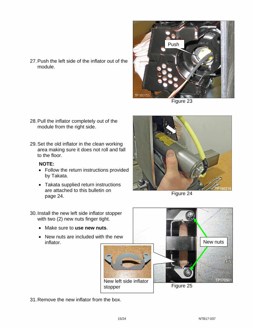
15/24 NTB17-037
Figure 23
Figure 24
Figure 25
27. Push the left side of the inflator out of the
module.
28. Pull the inflator completely out of the
module from the right side. 29. Set the old inflator in the clean working
area making sure it does not roll and fall to the floor.
NOTE: Follow the return instructions provided
by Takata.
Takata supplied return instructions are attached to this bulletin on page 24.
30. Install the new left side inflator stopper
with two (2) new nuts finger tight.
Make sure to use new nuts.
New nuts are included with the new inflator.
31. Remove the new inflator from the box.
Push
New nuts
New left side inflator stopper

16/24 NTB17-037
Figure 26
Figure 27
Figure 28
32. Slide the new inflator into the module
assembly from the right side.
Slide purple end in first. 33. Make sure the inflator is positioned /
oriented correctly as shown.
The flat side of the inflator end (on the left side) must face the flat side of the inflator stopper.
34. Install the new right side inflator stopper
with two (2) new nuts finger tight.
Make sure to use new nuts.
New nuts are included with the new inflator.
Flat side of inflator end
Flat side of new left side inflator stopper
New nuts
New right side inflator stopper

17/24 NTB17-037
35. Make sure the inflator is pushed all the way into its housing and up to the left side
inflator stopper– no gap on the left side (see Figure 29). 36. Make sure there is no gap between the right side inflator stopper and the inflator (see
Figure 29).
Figure 29
No gap on the left side
No gap on right side
Right side inflator stopper
Left side inflator stopper
Inflator Inflator
18/24 NTB17-037
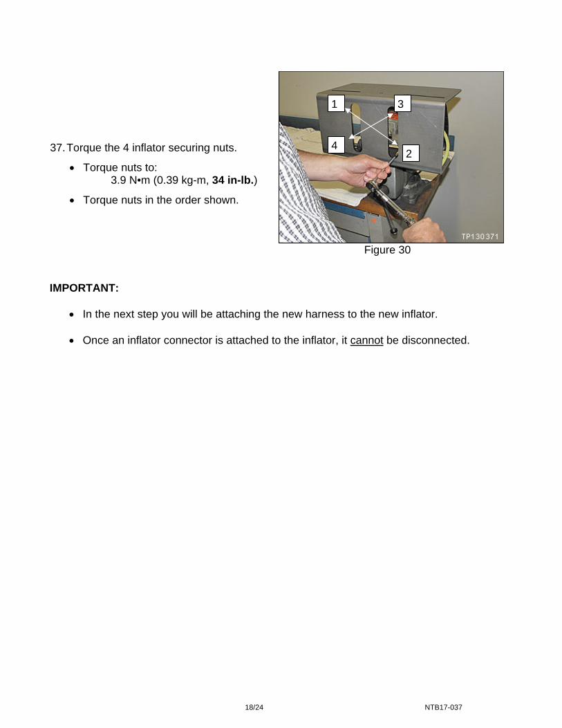
Figure 30
IMPORTANT:
In the next step you will be attaching the new harness to the new inflator.
Once an inflator connector is attached to the inflator, it cannot be disconnected.
37. Torque the 4 inflator securing nuts.
Torque nuts to: 3.9 N•m (0.39 kg-m, 34 in-lb.)
Torque nuts in the order shown.
1
42
3

19/24 NTB17-037
38. Attach the new harness to the inflator.
Make sure to attach the harness correctly - refer to Figures 31, 32 and 33.
The short lead of the harness will be attached to the purple end of the inflator.
The long lead of the harness will be attached to the white end of the inflator.
Figure 31
Figure 32
Inflator end Inflator connector
Make sure the T shape at the inflator end aligns with the T shape of the connector.
T shape
Short harness lead
Long harness lead
Left side (purple) Right side (white)
Module shown outside support to illustrate harness layout.
EXAMPLE ONLY
Purple side White side

20/24 NTB17-037
Make sure the inflator connectors are fully engaged / seated (see Figure 33).
Figure 33 39. Remove the module from the support and set it on the clean working area.
Figure 34
Less than 2 mm - OK
More than 2 mm - NG
40. Remove the module support bracket
from the module frame.
Support bracket

21/24 NTB17-037
Figure 35
43. Reinstall the module into the vehicle in reverse order of removal.
Make sure to use new module mounting bolts included with the new inflator. 44. Return the removed (old / non-deployed) inflator in the box that the new inflator
came in.
Follow the return instructions provided by Takata.
Takata supplied return instructions are attached to this bulletin on page 24. 45. Re-connect both battery cables – positive cable first. 46. Reset the clock and the radio settings. 47. Turn the ignition from OFF to ON and observe the air bag warning light:
Light should illuminate for 7 seconds and then go out.
NOTE: If the Air Bag Warning light does not operate as described above there may be an issue not covered by this campaign. Refer to ASIST and the appropriate Service Manual for additional diagnostic and repair information.
41. Reinstall the instrument panel finisher to
the module assembly. 42. Route and attach the harness to the
harness guides, and attach harness clips as shown.
Attachment points
Instrument panel finisher

22/24 NTB17-037
PARTS INFORMATION
DESCRIPTION PART # QUANTITY Inflator for
Front Passenger Air Bag Module
(Includes inflator, harness, module mounting bolts,
inflator stoppers and inflator securing nuts)
98561 – EM39A 1
Shorting Pin (Insulation Displacement
Connector for 22-18 gauge wire)
NAPA item # 784566
Grainger Item # 4YT50
or equivalent available from local auto supply
2
NOTE:
Make sure to return the removed (old / non-deployed) inflator in the box that the new inflator came in.
Follow the return instructions provided by Takata.
Takata supplied return instructions are attached to this bulletin on page 24.
23/24 NTB17-037
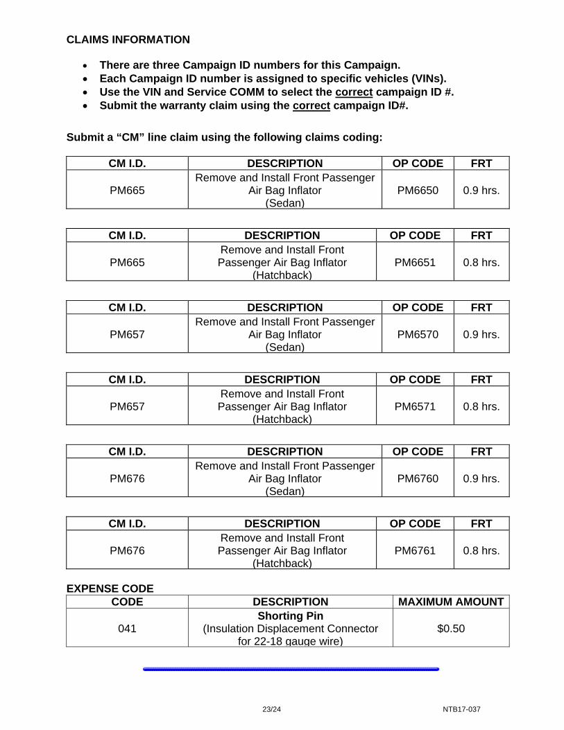
CLAIMS INFORMATION
There are three Campaign ID numbers for this Campaign. Each Campaign ID number is assigned to specific vehicles (VINs). Use the VIN and Service COMM to select the correct campaign ID #. Submit the warranty claim using the correct campaign ID#.
Submit a “CM” line claim using the following claims coding:
CM I.D. DESCRIPTION OP CODE FRT
PM665 Remove and Install Front Passenger
Air Bag Inflator (Sedan)
PM6650 0.9 hrs.
CM I.D. DESCRIPTION OP CODE FRT
PM665 Remove and Install Front Passenger Air Bag Inflator
(Hatchback)PM6651 0.8 hrs.
CM I.D. DESCRIPTION OP CODE FRT
PM657 Remove and Install Front Passenger
Air Bag Inflator (Sedan)
PM6570 0.9 hrs.
CM I.D. DESCRIPTION OP CODE FRT
PM657 Remove and Install Front Passenger Air Bag Inflator
(Hatchback)PM6571 0.8 hrs.
CM I.D. DESCRIPTION OP CODE FRT
PM676 Remove and Install Front Passenger
Air Bag Inflator (Sedan)
PM6760 0.9 hrs.
CM I.D. DESCRIPTION OP CODE FRT
PM676 Remove and Install Front Passenger Air Bag Inflator
(Hatchback)PM6761 0.8 hrs.
EXPENSE CODE
CODE DESCRIPTION MAXIMUM AMOUNT
041 Shorting Pin
(Insulation Displacement Connector for 22-18 gauge wire)
$0.50

24/24 NTB17-037
Takata Document