volvo vn peoplenet mobile gateway® install guide...b1-2=f12 b1-5=f61 b1-3=f55 b1-6=f66 click here...
TRANSCRIPT

Volvo VNPeopleNet Mobile Gateway® Install Guide

Hardware Overview
Display
Display
Cable
Power
Assembly
2-Pin Main
Cable
PMG Aux
Cable
PMGAntenna
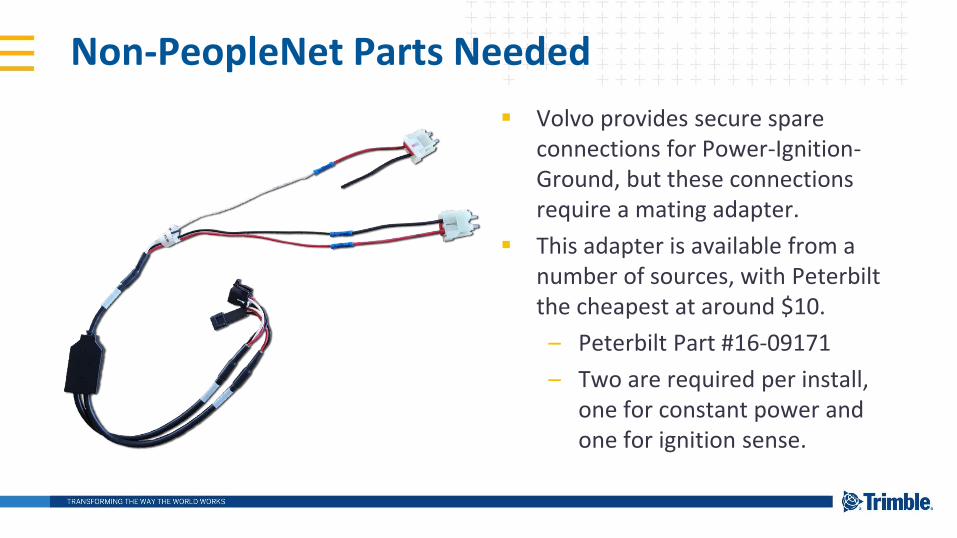
Non-PeopleNet Parts Needed
Volvo provides secure spare connections for Power-Ignition-Ground, but these connections require a mating adapter.
This adapter is available from a number of sources, with Peterbiltthe cheapest at around $10.
– Peterbilt Part #16-09171
– Two are required per install, one for constant power and one for ignition sense.

Install Overview
Display
Option 1
Engine
DataPower
Antenna
PMG
Display
Option 2

Dash Disassembly
1 Remove the screws
holding the fuse panel
cover and raise it up.
2 Pop out the center
dash cover.
3 Remove the 5 screws
holding the lower
storage space and pop
it out from the front.
4 Pop off the dash liner
beginning on the right.
Slide right at the
steering column.
5 Remove the two
switch panels.
5 Remove the two
switch panels.
5 Remove the two
switch panels.

Display Option 1
Relocate the switches
on the right-hand panel
to the left-hand panel.
Mount the RAM base to
the right-hand switch panel
using bolts and a backing
plate or large washers.
Feed the display cable into
the dash through a blank
switch position.

Display Option 2
For Automatic Transmission
vehicles, mount the RAM to the
center dash using bolts and a
backing plate or large washers.

Antenna
Pop out the left-hand vent.
Clean the top of the air-duct
behind it with an alcohol
swab and clean paper towel,
then attach the antenna to
the air-duct.
Bundle the bulk of the
antenna cables behind the
passenger dash, then feed
the connectors out the lower
dash.

Power AssemblySplice the white Ignition
Sense lead to the red
lead on one PACCAR
connector
Splice the red Constant
Power lead to the red
lead on the other
PACCAR connector
Splice the black Ground
lead to the black lead
on either PACCAR
connector

Power Connections
Insert the Ignition connector
into one of the right-hand 3
spare positions
Insert the Constant Power
connector into one of the
left-hand 3 spare positions
Add fuses to the vehicle fuse positions
corresponding to the spares. Check the
fuse map on the panel cover to confirm the
locations.
Battery Power Ignition
B1-1=F11 B1-4=F31
B1-2=F12 B1-5=F61
B1-3=F55 B1-6=F66
Click here to view a short
video of this process.

Engine Data
Connect the “Volvo” pigtail to the
black PMG 2-pin connector and
plug that into the matching
J1708 connector.
NOTE: This connection is not
necessary on vehicles built after
2012.
Disconnect the vehicle’s
terminating resistor and
insert it in the gray
PMG female 2-pin
connector.
Connect the gray PMG male 2-pin to the
vehicle J1939 connector.
NOTE: Some Volvos were built with the
yellow/green reversed. Verify yellow-to-yellow
and green-to-green.
Click here to view a
short video of this
process.

Correcting a Reversed J1939FOLLOW THESE INSTRUCTIONS ONLY IF THE VOLVO CONNECTOR HAS REVERSED YELLOW/GREEN
Note the reversed
yellow/green
Remove the orange
insert from the vehicle
connector
Release the lock tabs
and reverse the wires
Confirm the correction

PMG Placement
Connect all cabling
then tuck the PMG to
the passenger’s side of
the doghouse, securing
with one zip tie.