voyager™ ii rooftop units -...
TRANSCRIPT

Cooling-only
TKD-TKH 155-175-200-250-265-290-340
Heat pump
WKD-WKH 125-155-200-265-290-340
Cooling-only with gas-fired heating
YKD-YKH 155-175-200-250
Heat pump with gas-fired heating
DKD/DKH 125-155-200-265-290-340
R410A Refrigerant
RT-PRC014-E4
Voyager™ II
Rooftop Units
RT-PRC014-E4_0513:BAT2 4.6.2013 13:53 Page 1

© 2013 Trane RT-PRC014-E4
RT-PRC014-E4_1112:BAT2 30.5.2013 11:01 Page 2
3RT-PRC014-E4
Contents
Features and Benefits 4
Options and Accessories 7
Selection Procedure 11
General Data 12
Sound Levels 16
Electrical Data 18
Dimensions and Weights 19
Controls 20
Mechanical Specifications 24
RT-PRC014-E4_1112:BAT2 30.5.2013 11:01 Page 3
Features and Benefits
RT-PRC014-E44
• The Micro requires no special tools torun the unit through its paces. Simplyplace a jumper between Test 1 and Test2 terminals on the Low Voltage TerminalBoard and the unit will walk through itsoperational steps automatically. Theunit automatically returns control to thezone sensor after stepping through thetest mode a single time, even if thejumper is left on the unit.
• As long as the unit has power and theLED is lit, the Micro is operational. Thelight indicates that the Micro isfunctioning properly.
• The Micro features expandeddiagnostic capabilities when utilizedwith Trane's Integrated Comfort™Systems.
• The Micro in the Voyager units has built-in anti-short-cycle timers, time delayrelays and minimum ''on'' time controls.These controls are functions of the Microand are factory tested to assure properoperation.
• The Micro softens electrical ''spikes'' bystaging on fans, compressors andheaters.
• The Intelligent Fallback or AdaptiveControl is a benefit to the buildingoccupant. If a component goes astray,the unit will continue to operate atpredetermined temperature set points.
• Intelligent Anticipation is a standardfeature of the Micro. It functionsconstantly as the Micro and zonesensor work together in harmony toprovide tighter comfort control thanconventional electro-mechanicalthermostats.
Drum And Tube Heat Exchanger
• The drum and tube heat exchanger isdesigned for increased efficiency andreliability and has utilized improvedtechnology incorporated in the largerooftop commercial units for almost20 years.
• The heat exchanger is manufacturedusing aluminized steel with stainlesssteel components for maximumdurability. The drum and tube design hasbeen tested and passed over150,000 cycles.
• The negative pressure gas valve will notallow gas flow unless the combustionblower is operating. This is one of ourunique safety features.
• The forced combustion blower suppliesa gas-air mixture through a singlestainless steel burner screen into asealed drum where ignition takes place.It is more reliable to operate andmaintain than a multiple burnersystem.
• The hot surface ignitor is a gas ignitiondevice which doubles as a safety deviceutilizing a continuous test to prove theflame.
Weather Tight Top and C abinet
• Voyager units incorporate the Trane-Tite-Top (T3 ). Each part of the top(three pieces) overlaps in such a waythat water cannot leak into the unit.These overlapped edges are gasketedand sealed to ensure superior waterintegrity.
• Quick- Access panels reduce thenumber of possible water entry points.
• For added water integrity, Voyager hasa raised 30 mm lip around the supplyand return of the downflow units toprevent water from blowing into theductwork.
Quality And Reliability
• The fan and idler arm assemblydesigns have been tested to over300,000 cycles each.
• All of Voyager's designs wererigorously rain tested at the factory toensure water integrity.
• We perform a 100% coil leak test at thefactory. The evaporator and condensercoils are leak tested at 1.4 MPa andpressure tested to 3.1 MPa.
• Every unit and its options receive a100% unit run test before leaving theproduction line to make sure it lives upto Trane r equirements.
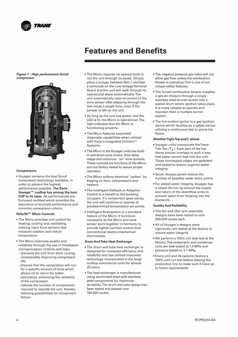
Figure 1 - High performance Scrollcompressor
Compressors
• Voyager contains the best Scrollcompressor technology available, inorder to achieve the highestperformance possible. The Trane
Voyager™ rooftop has among the best
COP in its class. All performances areEurovent certified which provides theassurance of accurate performance andcommon comparison criteria
ReliaTel™ Micro Controls
• The Micro provides unit control forheating, cooling and ventilatingutilizing input from sensors thatmeasure outdoor and indoortemperature.
• The Micro improves quality andreliability through the use of timetestedmicroprocessor controls and logic.- prevents the unit from short cycling,
considerably improving compressorlife.
- ensures that the compressor will runfor a specific amount of time whichallows oil to return for betterlubrication, enhancing the reliabilityof the compressor.
- reduces the number of componentsrequired to operate the unit, therebyreducing possibilities for componentfailure.
RT-PRC014-E4_1112:BAT2 30.5.2013 11:01 Page 4
Features and Benefits
5RT-PRC014-E4
Ease Of Installation
Voyager units provide many time andmoney saving features.
Conversionless Units
• The dedicated design units (eitherdownflow or horizontal) require nopanel removal or alteration time toconvert in the field.
• Horizontal units come complete withduct flanges so the contractor doesn'thave to field fabricate them.
Improved Airflow
• U-shaped airflow allows for improvedstatic capabilities.
Single Side Access
• No more than three screws must beremoved to access components.
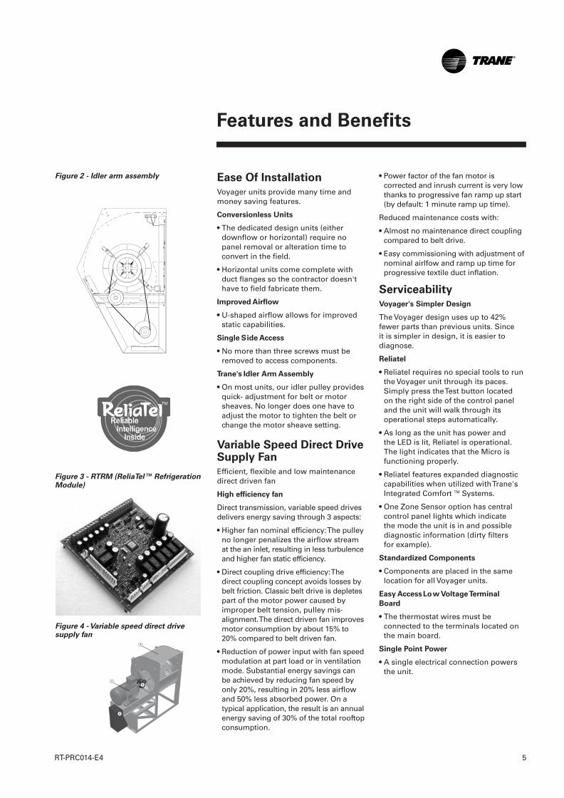
Trane's Idler Arm Assembly
• On most units, our idler pulley providesquick- adjustment for belt or motorsheaves. No longer does one have toadjust the motor to tighten the belt orchange the motor sheave setting.
Variable Speed Direct DriveSupply Fan
Efficient, flexible and low maintenancedirect driven fan
High efficiency fan
Direct transmission, variable speed drivesdelivers energy saving through 3 aspects:
• Higher fan nominal efficiency: The pulleyno longer penalizes the airflow streamat the an inlet, resulting in less turbulenceand higher fan static efficiency.
• Direct coupling drive efficiency: Thedirect coupling concept avoids losses bybelt friction. Classic belt drive is depletespart of the motor power caused byimproper belt tension, pulley mis-alignment. The direct driven fan improvesmotor consumption by about 15% to20% compared to belt driven fan.
• Reduction of power input with fan speedmodulation at part load or in ventilationmode. Substantial energy savings canbe achieved by reducing fan speed byonly 20%, resulting in 20% less airflowand 50% less absorbed power. On atypical application, the result is an annualenergy saving of 30% of the total rooftopconsumption.
• Power factor of the fan motor iscorrected and inrush current is very lowthanks to progressive fan ramp up start(by default: 1 minute ramp up time).
Reduced maintenance costs with:
• Almost no maintenance direct couplingcompared to belt drive.
• Easy commissioning with adjustment ofnominal airlfow and ramp up time forprogressive textile duct inflation.
Serviceability
Voyager's Simpler Design
The Voyager design uses up to 42%fewer parts than previous units. Sinceit is simpler in design, it is easier todiagnose.
Reliatel
• Reliatel requires no special tools to runthe Voyager unit through its paces.Simply press the Test button locatedon the right side of the control paneland the unit will walk through itsoperational steps automatically.
• As long as the unit has power andthe LED is lit, Reliatel is operational.The light indicates that the Micro isfunctioning properly.
• Reliatel features expanded diagnosticcapabilities when utilized with Trane'sIntegrated Comfort TM Systems.
• One Zone Sensor option has centralcontrol panel lights which indicatethe mode the unit is in and possiblediagnostic information (dirty filtersfor example).
Standardized Components
• Components are placed in the samelocation for all Voyager units.
Easy Access Low Voltage Terminal
Board
• The thermostat wires must beconnected to the terminals located onthe main board.
Single Point Power
• A single electrical connection powersthe unit.
Figure 2 - Idler arm assembly
Figure 3 - RTRM (ReliaTel™ RefrigerationModule)
Figure 4 - Variable speed direct drivesupply fan
RT-PRC014-E4_1112:BAT2 30.5.2013 11:01 Page 5
Features and Benefits
RT-PRC014-E46
An Answer to MarketNeeds
Capacity Modulation
• Voyager features dual Scrollcompressor units. The dual compressormodels are outstanding for humiditycontrol, light load cooling conditionsand system back-up applications.
Low Ambient Cooling
• All Voyager units have coolingcapabilities down to -18°C as standard.
Flexible Applications
• Thanks to its high static pressurecapabilities, the Voyager can replace anolder machine with old ductwork and,in some cases, improve the comfortthrough better air distribution.
Indoor Air Quality
• Filters - all rooftops are shipped withthrowaway filters to be used during thefirst days of operation (usually the jobsite is not completely clean, and highefficiency filters would get dirty in a fewhours - this would be a waste ofmoney) or G4/EU4 filters for regularoperation.
• Panels in the indoor air section have afire-resistant (MO) aluminum foil-facedinsulation. There is no more insulationpaticules carried in the air. It can becleaned which is paricuarly interestingfor restaurant applications.
• All our drain pans are sloped. We thusavoid water stagnation that engenderscorrosion and micro-organism life suchas mold and fungi.
Reliatel Benefits
• Reliatel in the Voyager units has built-inanti-short-cycle timers, time delayrelays and minimum ''on'' timecontrols. These controls are functions ofReliatel and are factory tested to assureproper operation.
• Reliatel softens electrical ''spikes'' bystaging on fans, compressors andheaters.
• The Intelligent Fallback or AdaptiveControl is a benefit to the buildingoccupant. If a component goes astray,the unit will continue to operate atpredetermined temperature set points.
• Intelligent Anticipation is a standardfeature of Reliatel. It functionsconstantly as Reliatel and zone sensorwork together in harmony to providetighter comfort control thanconventional electro-mechanicalthermostats.
Downflow And Horizontal Economizers
• Economizers come with a comparativeenthalpy control.
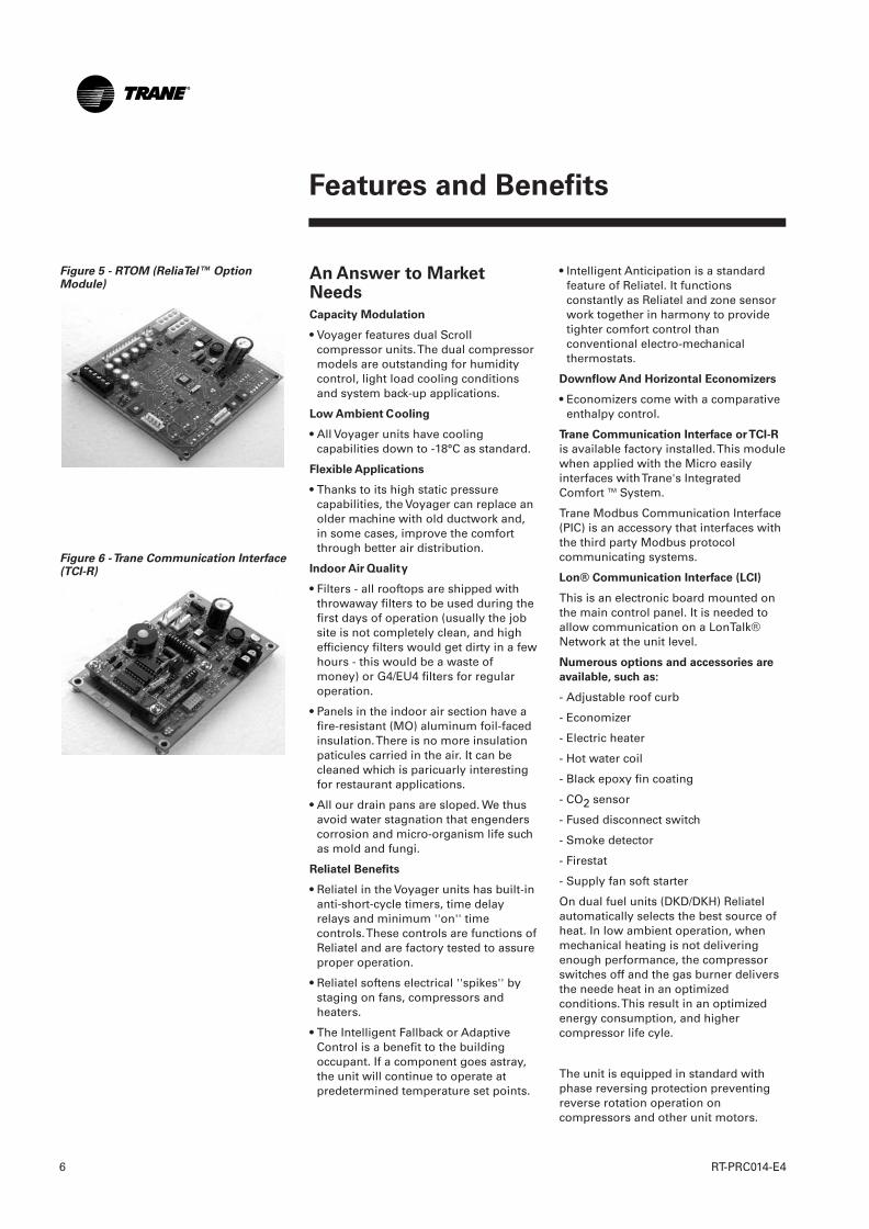
Trane Communication Interface or TCI-R
is available factory installed. This modulewhen applied with the Micro easilyinterfaces with Trane's IntegratedComfort TM System.
Trane Modbus Communication Interface(PIC) is an accessory that interfaces withthe third party Modbus protocolcommunicating systems.
Lon® Communication Interface (LCI)
This is an electronic board mounted onthe main control panel. It is needed toallow communication on a LonTalk®Network at the unit level.
Numerous options and accessories are
available, such as:
- Adjustable roof curb
- Economizer
- Electric heater
- Hot water coil
- Black epoxy fin coating
- CO2 sensor
- Fused disconnect switch
- Smoke detector
- Firestat
- Supply fan soft starter
On dual fuel units (DKD/DKH) Reliatelautomatically selects the best source ofheat. In low ambient operation, whenmechanical heating is not deliveringenough performance, the compressorswitches off and the gas burner deliversthe neede heat in an optimizedconditions. This result in an optimizedenergy consumption, and highercompressor life cyle.
The unit is equipped in standard withphase reversing protection preventingreverse rotation operation oncompressors and other unit motors.
Figure 6 - Trane Communication Interface(TCI-R)
Figure 5 - RTOM (ReliaTel™ OptionModule)
RT-PRC014-E4_1112:BAT2 30.5.2013 11:01 Page 6
Options and Accessories
7RT-PRC014-E4
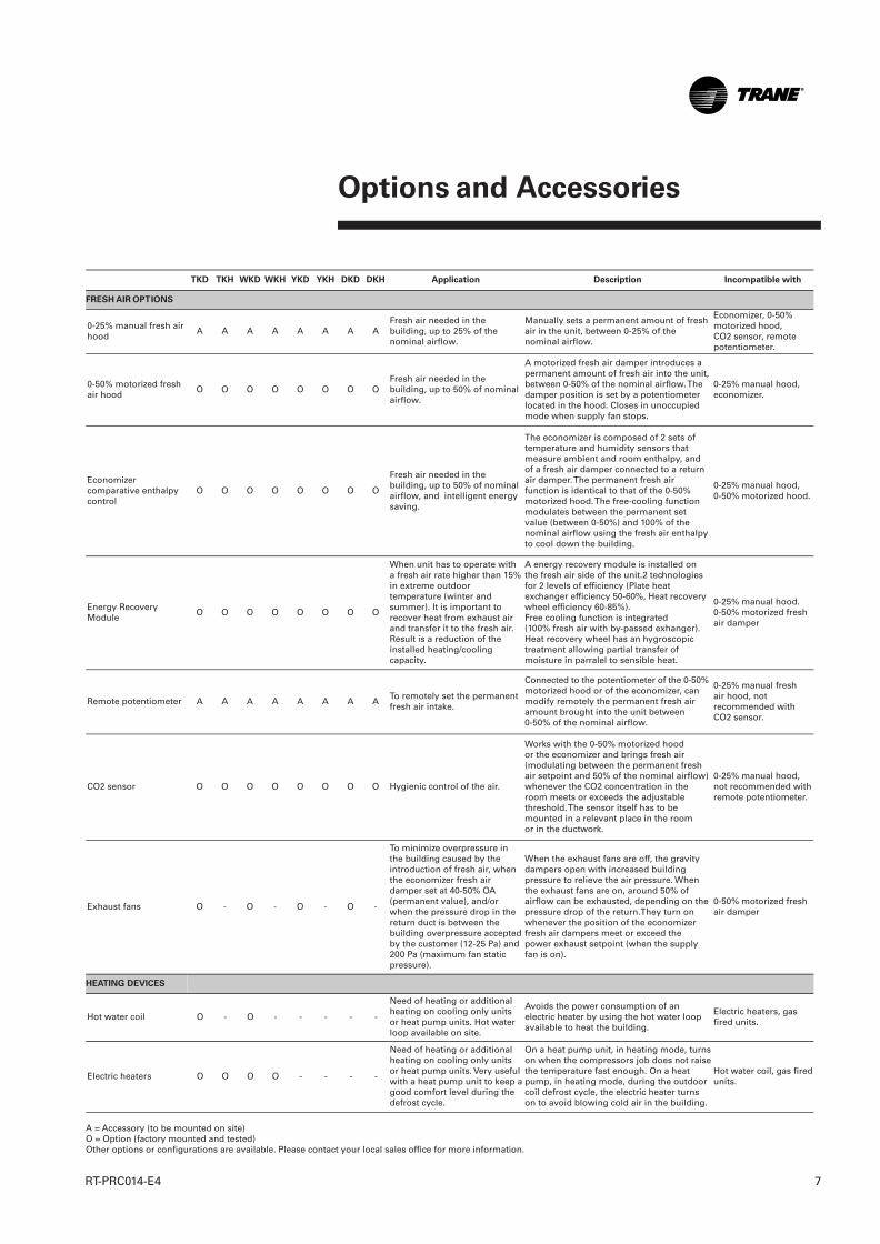
A = Accessory (to be mounted on site)O = Option (factory mounted and tested)Other options or configurations are available. Please contact your local sales office for more information.
TKD TKH WKD WKH YKD YKH DKD DKH Application Description Incompatible with
FRESH AIR OPTIONS
0-25% manual fresh airhood
A A A A A A A AFresh air needed in thebuilding, up to 25% of thenominal airflow.
Manually sets a permanent amount of freshair in the unit, between 0-25% of thenominal airflow.
Economizer, 0-50%motorized hood, CO2 sensor, remotepotentiometer.
0-50% motorized freshair hood
O O O O O O O OFresh air needed in thebuilding, up to 50% of nominalairflow.
A motorized fresh air damper introduces apermanent amount of fresh air into the unit,between 0-50% of the nominal airflow. Thedamper position is set by a potentiometerlocated in the hood. Closes in unoccupiedmode when supply fan stops.
0-25% manual hood,economizer.
Economizercomparative enthalpycontrol
O O O O O O O O
Fresh air needed in thebuilding, up to 50% of nominalairflow, and intelligent energysaving.
The economizer is composed of 2 sets oftemperature and humidity sensors thatmeasure ambient and room enthalpy, andof a fresh air damper connected to a returnair damper. The permanent fresh airfunction is identical to that of the 0-50%motorized hood. The free-cooling functionmodulates between the permanent setvalue (between 0-50%) and 100% of thenominal airflow using the fresh air enthalpyto cool down the building.
0-25% manual hood, 0-50% motorized hood.
Energy RecoveryModule
O O O O O O O O
When unit has to operate witha fresh air rate higher than 15%in extreme outdoortemperature (winter andsummer). It is important torecover heat from exhaust airand transfer it to the fresh air.Result is a reduction of theinstalled heating/coolingcapacity.
A energy recovery module is installed onthe fresh air side of the unit.2 technologiesfor 2 levels of efficiency (Plate heatexchanger efficiency 50-60%, Heat recoverywheel efficiency 60-85%).Free cooling function is integrated(100% fresh air with by-passed exhanger).Heat recovery wheel has an hygroscopictreatment allowing partial transfer ofmoisture in parralel to sensible heat.
0-25% manual hood. 0-50% motorized freshair damper
Remote potentiometer A A A A A A A ATo remotely set the permanentfresh air intake.
Connected to the potentiometer of the 0-50%motorized hood or of the economizer, canmodify remotely the permanent fresh airamount brought into the unit between 0-50% of the nominal airflow.
0-25% manual freshair hood, notrecommended withCO2 sensor.
CO2 sensor O O O O O O O O Hygienic control of the air.
Works with the 0-50% motorized hoodor the economizer and brings fresh air(modulating between the permanent freshair setpoint and 50% of the nominal airflow)whenever the CO2 concentration in theroom meets or exceeds the adjustablethreshold. The sensor itself has to bemounted in a relevant place in the roomor in the ductwork.
0-25% manual hood,not recommended withremote potentiometer.
Exhaust fans O - O - O - O -
To minimize overpressure inthe building caused by theintroduction of fresh air, whenthe economizer fresh airdamper set at 40-50% OA(permanent value), and/orwhen the pressure drop in thereturn duct is between thebuilding overpressure acceptedby the customer (12-25 Pa) and200 Pa (maximum fan staticpressure).
When the exhaust fans are off, the gravitydampers open with increased buildingpressure to relieve the air pressure. Whenthe exhaust fans are on, around 50% ofairflow can be exhausted, depending on thepressure drop of the return.They turn onwhenever the position of the economizerfresh air dampers meet or exceed thepower exhaust setpoint (when the supplyfan is on).
0-50% motorized freshair damper
HEATING DEVICES
Hot water coil O - O - - - - -
Need of heating or additionalheating on cooling only unitsor heat pump units. Hot waterloop available on site.
Avoids the power consumption of anelectric heater by using the hot water loopavailable to heat the building.
Electric heaters, gasfired units.
Electric heaters O O O O - - - -
Need of heating or additionalheating on cooling only unitsor heat pump units. Very usefulwith a heat pump unit to keep agood comfort level during thedefrost cycle.
On a heat pump unit, in heating mode, turnson when the compressors job does not raisethe temperature fast enough. On a heatpump, in heating mode, during the outdoorcoil defrost cycle, the electric heater turnson to avoid blowing cold air in the building.
Hot water coil, gas firedunits.
RT-PRC014-E4_1112:BAT2 30.5.2013 11:01 Page 7
Options and Accessories
RT-PRC014-E48
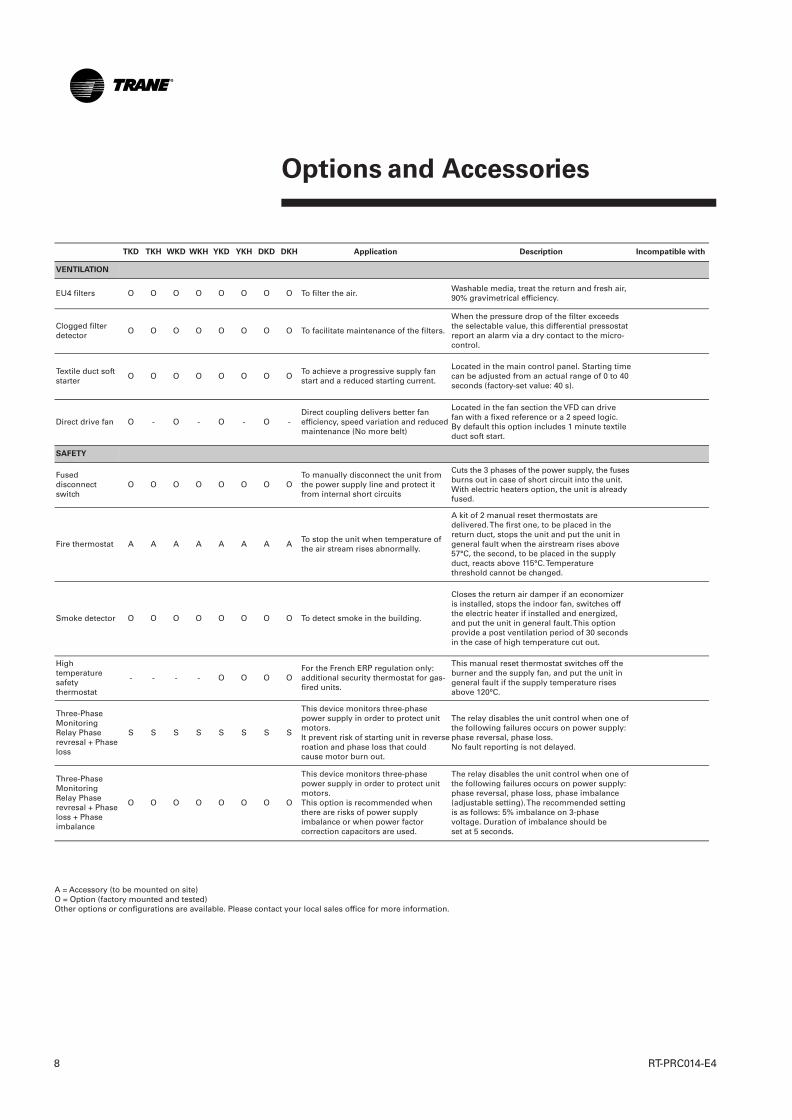
A = Accessory (to be mounted on site)O = Option (factory mounted and tested)Other options or configurations are available. Please contact your local sales office for more information.
TKD TKH WKD WKH YKD YKH DKD DKH Application Description Incompatible with
VENTILATION
EU4 filters O O O O O O O O To filter the air.Washable media, treat the return and fresh air,90% gravimetrical efficiency.
Clogged filterdetector
O O O O O O O O To facilitate maintenance of the filters.
When the pressure drop of the filter exceedsthe selectable value, this differential pressostatreport an alarm via a dry contact to the micro-control.
Textile duct softstarter
O O O O O O O OTo achieve a progressive supply fanstart and a reduced starting current.
Located in the main control panel. Starting timecan be adjusted from an actual range of 0 to 40seconds (factory-set value: 40 s).
Direct drive fan O - O - O - O -Direct coupling delivers better fanefficiency, speed variation and reducedmaintenance (No more belt)
Located in the fan section the VFD can drivefan with a fixed reference or a 2 speed logic.By default this option includes 1 minute textileduct soft start.
SAFETY
Fuseddisconnectswitch
O O O O O O O OTo manually disconnect the unit fromthe power supply line and protect itfrom internal short circuits
Cuts the 3 phases of the power supply, the fusesburns out in case of short circuit into the unit.With electric heaters option, the unit is alreadyfused.
Fire thermostat A A A A A A A ATo stop the unit when temperature ofthe air stream rises abnormally.
A kit of 2 manual reset thermostats aredelivered. The first one, to be placed in thereturn duct, stops the unit and put the unit ingeneral fault when the airstream rises above57°C, the second, to be placed in the supplyduct, reacts above 115°C. Temperaturethreshold cannot be changed.
Smoke detector O O O O O O O O To detect smoke in the building.
Closes the return air damper if an economizeris installed, stops the indoor fan, switches offthe electric heater if installed and energized,and put the unit in general fault. This optionprovide a post ventilation period of 30 secondsin the case of high temperature cut out.
Hightemperaturesafetythermostat
- - - - O O O OFor the French ERP regulation only:additional security thermostat for gas-fired units.
This manual reset thermostat switches off theburner and the supply fan, and put the unit ingeneral fault if the supply temperature risesabove 120°C.
Three-PhaseMonitoringRelay Phaserevresal + Phaseloss
S S S S S S S S
This device monitors three-phasepower supply in order to protect unitmotors. It prevent risk of starting unit in reverseroation and phase loss that couldcause motor burn out.
The relay disables the unit control when one ofthe following failures occurs on power supply:phase reversal, phase loss.No fault reporting is not delayed.
Three-PhaseMonitoringRelay Phaserevresal + Phaseloss + Phaseimbalance
O O O O O O O O
This device monitors three-phasepower supply in order to protect unitmotors. This option is recommended whenthere are risks of power supplyimbalance or when power factorcorrection capacitors are used.
The relay disables the unit control when one ofthe following failures occurs on power supply:phase reversal, phase loss, phase imbalance(adjustable setting). The recommended settingis as follows: 5% imbalance on 3-phasevoltage. Duration of imbalance should beset at 5 seconds.
RT-PRC014-E4_1112:BAT2 30.5.2013 11:01 Page 8

Options and Accessories
9RT-PRC014-E4
A = Accessory (to be mounted on site)O = Option (factory mounted and tested)Other options or configurations are available. Please contact your local sales office for more information.
TKD TKH WKD WKH YKD YKH DKD DKH Application Description Incompatible with
ROOFCURBS
Standard roofcurb A - A - A - A -Connection between a flat roof and therooftop.
Supports the rooftop and ensureswatertightness roof/roofcurb/rooftop,and easy connection of the ductwork .
Adjustableroofcurb.
Adjustable roofcurb A - A - A - A -Connection between a sloped roof andthe rooftop.
Supports the rooftop and ensureswatertightness roof/roofcurb/rooftop,and easy connection of the ductwork,correcting up to 8% slope.
Standard roofcurb.
CONTROL
Reliatel™ OptionsModule (RTOM)
O O O O O O O O
Required for some optional ReliaTel™devices (frostat, clogged filter switch,fan failure switch, discharge air sensor(DAS) used for supply air temperingand ICS input data, smoke detector,external on/off switch).
Communication interface betweenthe ReliaTel™ Refrigeration Module(RTRM) and some options.
T CI - R O O O O O O O O
To communicate with Trane IntegratedComfort Systems, such as the TracerSummit™, the Tracker™ or a Varitrac™system (CCP2).
Communication interface betweena Trane ICS device and a Voyager™.
THS/P 03, LCI-R
L CI - R O O O O O O O OTo communicate on a LonTalk®network at the unit level.
Communication interface betweena LonTalk® device and a Voyager™.
THS/P 03, TCI-R
P I C A A A A A A A ATo communicate on a Modbus networkat the unit level.
Communication interface betweenModbus device and a Voyager™.Need to order TCI-R with PIC.
THS/P 03, LCI-R
T HS0 3 A A A A A A A AControl of 1 cooling-only, heat pump orgas-fired rooftop.
Electronic thermostat, 2 stagescooling, 1 stage compressor heating,2 stages auxiliary heating. No CTI cardneeded, communicates in the samelanguage as the rooftop micro-controland uses 100% of its advanced controlfeatures
TCI-R, LCI-R
T HP 0 3 A A A A A A A AControl of 1 cooling-only, heat pump orgas-fired rooftop.
Electronic programmable thermostat,2 stages cooling, 1 stage compressorheating, 2 stages auxiliary heating,LCD screen. Communicates in thesame language as the rooftop micro-control and uses 100% of its advancedcontrol features.
TCI-R, LCI-R
Remote sensor box forTHS/THP03
A A A A A A A ANeed of remote or additional sensorswith THS/THP03
Senses the temperature and sends theinformation to the THS/P 03.
Antifreeze thermostat O O O O O O O O
Additional device to prevent the indoorcoil from icing. Very useful when alarge amount of cold air is blown intothe unit during the cooling mode.
A sensor is placed on the indoor coiland stops the compressors for theperiod of time needed, as soon as thecoil approaches the freezing point(in cooling mode).
Remote fault relay O O O O O O O O To send alarms signals to a local BMS.
Uses the compressor/heating/fan/power supply alarm output signalsfrom the micro-control and reportsthem into one dry contact.
RT-PRC014-E4_1112:BAT2 30.5.2013 11:01 Page 9

Options and Accessories
RT-PRC014-E410
A = Accessory (to be mounted on site)O = Option (factory mounted and tested)Other options or configurations are available. Please contact your local sales office for more information.
TKD TKH WKD WKH YKD YKH DKD DKH Application Description Incompatible with
MISCELLANEOUS
Oversized drive / motor O O O O O O O O High static pressure needs.Increases the fans speed via oversizedpulleys/belts and/or oversized motors.
Black epoxy coating oncondenser
O O O O O O O O Sea side application.The black epoxy coating slows downthe corrosion process on thealuminum fins.
Black epoxy coating oncondenser andevaporator
O O O O O O O OSea side application when a fresh airdevice is used.
The black epoxy coating slows downthe corrosion process on thealuminum fins.
RT-PRC014-E4_1112:BAT2 30.5.2013 11:01 Page 10
Selection Procedure
11RT-PRC014-E4
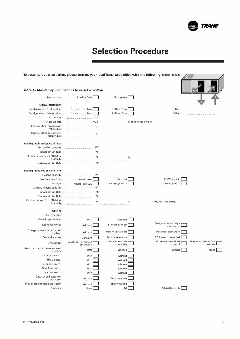
System type Cooling Only Heat pump
Airflow information
Configuration of return duct 1 - Horizontal flow 2 - Downflow Other ........................................
Configuration of supply duct 3 - Horizontal flow 4 - Downflow Other ........................................
Unit airflow ........................................ m3/h
Fresh air rate ........................................ m3/h ........................................ % of nominal airflow
External static pressure onreturn duct ........................................
Pa
External static pressure onsupply duct ........................................
Pa
Cooling mode design conditions
Unit cooling capacity ........................................ kW
Indoor air Dry Bulb ........................................ °C
Indoor air wet Bulb / RelativeHumidity ........................................
°C........................................
%
Outdoor air Dry Bulb ........................................ °C
Heating mode design conditions
Heating capacity ........................................ kW
Auxiliary heat type Electric Heat Gas Heat Hot Water coil
Gas type Natural gas G20 Natural gas G25 Propane gas G31
Auxiliary heating capacity ........................................ kW
Indoor air Dry Bulb ........................................ °C
Outdoor air Dry Bulb ........................................ °C
Outdoor air wet Bulb / RelativeHumidity ........................................
°C........................................
% (only for Heat pump)
Options
Air filter class ........................................
Variable speed drive With Without
Economizer type Without Manual fresh airComparative enthalpy
economizer
Energy recovery on exhaust /fresh air Without Rotary heat wheel Plate heat exchanger
Fresh air control Constant Remote reference CO2 sensor controled
Unit control Local control withoutscheduling
Local control withscheduling
Multi-unit centralizedcontrol
Remote relay interfacecontrol
Remote control communicationinterface LON Modbus Bacnet Trane
Smoke detector With Without
Fire detector With Without
Disconnect switch With Without
Dirty filter switch With Without
Fan fail switch With Without
Outdoor coil corrosionprotection Without Epoxy coating
Indoor coil corrosion protection Without Epoxy coating
Roofcurb None Flat Adjustable pitch
Table 1 - Mandatory informations to select a rooftop
To obtain product selection, please contact your local Trane sales office with the following information:
RT-PRC014-E4_1112:BAT2 30.5.2013 11:01 Page 11

General Data
RT-PRC014-E412
(1) At Eurovent rating conditions: Indoor return Air (27°C DB / 19°C WB) - Ambiant 35°C(2) per motor(3) For standard unit, with oversized drive, without electric heater options(4) At the nominal airflow with standard drive
(5) At the nominal airflow with oversized drive when available(6) At 10m from the unit in a free fieldElectrical & refrigerant charge Data are subject to change without notice. Please referto unit nameplate data.
Table 2 - General data TKD/TKH, YKD/YKH
TKD / TKH TKD / TKH TKD / TKH TKD / TKH TKD/H TKD/H TKD/H YKD / YKH YKD / YKH YKD / YKH YKD / YKH 155 175 200 250 265 290 340Eurovent Performances (1) R410A R410A R410A R410A R410A R410A R410A
Net Cooling Capacity (kW) 43.9 50.6 56.5 68.0 73.8 85.6 95.2Total Power input in cooling (kW) 14.4 16.9 18.1 21.7 25.1 28.8 33.9EER 3.04 2.99 3.12 3.14 2.94 2.97 2.81Eurovent Efficiency class Cooling A B A A B B B
Main Power supply V/Ph/Hz 400/3/50 400/3/50 400/3/50 400/3/50 400/3/50 400/3/50 400/3/50Outdoor sound power level env. (dBA) 85 85 86 86 86 88 89Indoor sound power level in duct (dBA) 74 77 77 82 83 83 85Outdoor sound pressure level env. (6) (dBA) 53 53 54 54 54 56 57
Unit amps
Unit rated amps (3) (A) 39.5 46.3 52.0 55.0 62.5 76.2 83.8Unit start-up amps (A) 109 118 175 176 184 205 248Unit power factor (1) 0.75 0.72 0.74 0.77 0.79 0.79 0.8
Electric Heater (TKD / TKH)
Heating Capacity (kW) 25 25 37.5 37.5 37.5 37.5 37.5Capacity steps (kW) 12.5 / 12.5 12.5 / 12.5 25 / 12.5 25 / 12.5 25 / 12.5 25 / 12.5 25 / 12.5Rated Amps (A) 36 36 54 54 54 54 54
Gas burner (YKD / YKH)
Heating Models G350 G350 G350 G350 N/A N/A N/AHeating Input (G20) (kW) 77 77 77 77 - - -Heating Output (kW) 69.3 69.3 69.3 69.3 - - -Steady State Efficiency (%) 90 90 90 90 - - -No. Burners # 1 1 1 1 - - -No. Stages # 2 2 2 2 - - -Gas Connection Pipe Size 3/4" NPT 3/4" NPT 3/4" NPT 3/4" NPT - - -
Compressor
Number # 2 2 2 2 2 2 2Type Scroll Scroll Scroll Scroll Scroll Scroll ScrollModel 5T / 9T 6T / 10T 9T / 9T 10T / 10T 12T / 12T 13T / 13T 15T / 15TRated Amps (1) (A) 8.4 / 15.4 10.6 / 16.5 15.0 / 15.0 16.8 / 16.8 18.4 / 18.4 18.9 / 18.9 22.3 / 22.3Locked rotor Amps (2) (A) 82 / 142 87 / 142 142 / 142 142 / 142 147 / 147 158 / 158 197 / 197
Outdoor Coil
Type Wavy Wavy Wavy Wavy Wavy Wavy WavyTube Size OD (mm) 9.52 9.52 9.52 9.52 9.52 9.52 9.52Face Area (m²) 2.23 2.62 3.00 3.39 3.39 4.26 4.26Rows / Fin series # / FPF 2 / 192 2 / 192 2 / 192 2 / 192 2 / 192 2 / 192 2 / 192
Indoor Coil
Type Wavy Wavy Wavy Wavy Wavy Wavy WavyTube Size OD (mm) 9.52 9.52 9.52 9.52 9.52 9.52 9.52Face Area (m²) 1.63 1.63 2.42 2.42 2.42 2.42 2.42Rows / Fin series # / FPF 3 / 180 3 / 180 2 / 180 3 / 168 3 / 168 4 / 168 4 / 168Refrigerant Control Exp. Valve Exp. Valve Exp. Valve Exp. Valve Exp. Valve Exp. Valve Exp. ValveDrain Connection No./Size (mm) 1 / 3/4" NPT 1 / 3/4" NPT 1 / 3/4" NPT 1 / 3/4" NPT 1 / 3/4" NPT 1 / 3/4" NPT 1 / 3/4" NPT
Outdoor Fan
Nominal Airflow (m3/h) 17300 18000 26700 27300 27300 39500 39500Type Axial Axial Axial Axial Axial Axial AxialDiameter (mm) 630 630 710 710 710 710 710Drive type Direct Direct Direct Direct Direct Direct DirectNumber # 2 2 2 2 2 3 3Motor HP (kW) 0.6 0.6 1.1 1.1 1.1 1.1 1.1Motor Rated Amps (1) (A) 1.2 1.2 2.5 2.5 2.5 2.5 2.5Motor RPM (rpm) 900 900 900 900 900 900 900
Indoor Fan
Minimum Airflow (m3/h) 6800 7880 8970 11280 11520 12960 14400Nominal Airflow (m3/h) 8500 9850 11210 14100 14400 16200 18000Maximum Airflow (m3/h) 10200 11820 13450 16920 17280 19440 21600Static pressure available (4) (Pa) 150 75 175 75 75 450 450Maximum static pressure available (5) (Pa) 350 375 450 375 375 500 500Type FC Centrifugal FC Centrifugal FC Centrifugal FC Centrifugal FC Centrifugal FC Centrifugal FC CentrifugalDiameter / Width (in / in) 15" / 15" 15" / 15" 18" / 18" 18" / 18" 18" / 18" 18" / 18" 18" / 18"Drive type Belt Belt Belt Belt Belt Belt BeltNumber # 1 1 1 1 1 1 1Motor HP (Standard/Oversized) (kW) 1.8 / 3.0 3.0 / 4.6 3.0 / 4.6 4.6 / - 4.6 / 5.5 7.5 / 9 7.5 / 9Motor Rated Amps (Standard/Oversized) (A) 4.0 / 6.4 6.4 / 9.0 6.4 / 9.0 9.0 / - 9.0 / 10.5 14.7 / 17.3 14.7 / 17.3Motor Locked rotor Amps (Standard/Oversized) (A) 36.4 / 57 57 / 71.9 57 / 71.9 71.9 / - 69 / 95 128 / 149 128 / 149Motor RPM (Standard/Oversized) (rpm) 1450 / 2870 2870 / 2900 2870 / 2900 2900 / - 2900 / 2900 2900 / 2900 2900 / 2900
RT-PRC014-E4_1112:BAT2 30.5.2013 11:01 Page 12
General Data
13RT-PRC014-E4
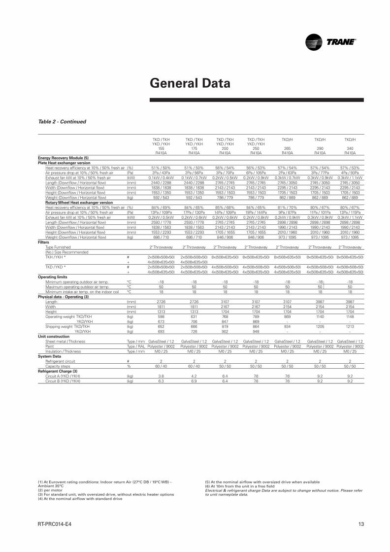
Table 2 - Continued
TKD / TKH TKD / TKH TKD / TKH TKD / TKH TKD/H TKD/H TKD/H YKD / YKH YKD / YKH YKD / YKH YKD / YKH 155 175 200 250 265 290 340 R410A R410A R410A R410A R410A R410A R410AEnergy Recovery Module (5)
Plate Heat exchanger version
Heat recovery efficiency at 10% / 50% fresh air (%) 51% / 50% 51% / 50% 56% / 54% 56% / 53% 57% / 54% 57% / 54% 57% / 53%Air pressure drop at 10% / 50% fresh air (Pa) 2Pa / 43Pa 2Pa / 56Pa 3Pa / 70Pa 6Pa / 105Pa 2Pa / 63Pa 3Pa / 77Pa 4Pa / 93PaExhaust fan kW at 10% / 50% fresh air (kW) 0.1kW / 0.4kW 0.1kW / 0.7kW 0.2kW / 0.5kW 0.2kW / 0.9kW 0.3kW / 0.7kW 0.3kW / 0.9kW 0.3kW / 1.1kWLength (Downflow / Horizontal flow) (mm) 2440 / 2288 2440 / 2288 2745 / 2745 2745 / 2745 2745 / 3050 2745 / 3050 2745 / 3050Width (Downflow / Horizontal flow) (mm) 1838 / 1838 1838 / 1838 2143 / 2143 2143 / 2143 2295 / 2143 2295 / 2143 2295 / 2143Height (Downflow / Horizontal flow) (mm) 1553 / 1350 1553 / 1350 1553 / 1503 1553 / 1503 1705 / 1503 1705 / 1503 1705 / 1503Weight (Downflow / Horizontal flow) (kg) 592 / 543 592 / 543 786 / 779 786 / 779 862 / 889 862 / 889 862 / 889Rotary Wheel Heat exchanger version
Heat recovery efficiency at 10% / 50% fresh air (%) 84% / 69% 84% / 65% 85% / 68% 84% / 65% 81% / 70% 80% / 67% 80% / 67%Air pressure drop at 10% / 50% fresh air (Pa) 13Pa / 109Pa 17Pa / 130Pa 14Pa / 109Pa 19Pa / 144Pa 9Pa / 87Pa 11Pa / 101Pa 13Pa / 115PaExhaust fan kW at 10% / 50% fresh air (kW) 0.2kW / 0.5kW 0.2kW / 0.6kW 0.2kW / 0.6kW 0.2kW / 0.8kW 0.2kW / 0.9kW 0.3kW / 0.9kW 0.3kW / 1.1kWLength (Downflow / Horizontal flow) (mm) 2593 / 1778 2593 / 1778 2745 / 2745 2745 / 2745 2898 / 2898 2898 / 2898 2898 / 2898Width (Downflow / Horizontal flow) (mm) 1838 / 1563 1838 / 1563 2143 / 2143 2143 / 2143 1990 / 2143 1990 / 2143 1990 / 2143Height (Downflow / Horizontal flow) (mm) 1553 / 2293 1553 / 2293 1705 / 1655 1705 / 1655 2010 / 1960 2010 / 1960 2010 / 1960Weight (Downflow / Horizontal flow) (kg) 686 / 710 686 / 710 846 / 906 846 / 906 973 / 1095 973 / 1095 973 / 1095
Filters
Type Furnished 2" Throwaway 2" Throwaway 2" Throwaway 2" Throwaway 2" Throwaway 2" Throwaway 2" Throwaway(No.) Size Recommended TKH / YKH * # 2x(508x508x50) 2x(508x508x50) 8x(508x635x50) 8x(508x635x50) 8x(508x635x50) 8x(508x635x50) 8x(508x635x50) + 4x(508x635x50) 4x(508x635x50) TKD / YKD * # 2x(508x508x50) 2x(508x508x50) 4x(508x508x50) 4x(508x508x50) 4x(508x508x50) 4x(508x508x50) 4x(508x508x50) + 4x(508x635x50) 4x(508x635x50) 4x(508x635x50) 4x(508x635x50) 4x(508x635x50) 4x(508x635x50) 4x(508x635x50)
Operating limits
Minimum operating outdoor air temp. °C -18 -18 -18 -18 -18 -18 -18Maximum operating outdoor air temp. °C 50 50 50 50 50 50 50Minimum intake air temp. on the indoor coil °C 18 18 18 18 18 18 18
Physical data - Operating (3)
Length (mm) 2726 2726 3107 3107 3107 3987 3987Width (mm) 1811 1811 2167 2167 2154 2154 2154Height (mm) 1313 1313 1704 1704 1704 1704 1704Operating weight TKD/TKH (kg) 598 631 768 789 869 1140 1148
YKD/YKH (kg) 673 706 847 869 - - -Shipping weight TKD/TKH (kg) 652 666 819 864 934 1205 1213
YKD/YKH (kg) 693 726 902 948 - - -Unit construction
Sheet metal / Thickness Type / mm GalvaSteel / 1.2 GalvaSteel / 1.2 GalvaSteel / 1.2 GalvaSteel / 1.2 GalvaSteel / 1.2 GalvaSteel / 1.2 GalvaSteel / 1.2Paint Type / RAL Polyester / 9002 Polyester / 9002 Polyester / 9002 Polyester / 9002 Polyester / 9002 Polyester / 9002 Polyester / 9002 Insulation / Thickness Type / mm M0 / 25 M0 / 25 M0 / 25 M0 / 25 M0 / 25 M0 / 25 M0 / 25
System Data
Refrigerant circuit # 2 2 2 2 2 2 2Capacity steps % 60 / 40 60 / 40 50 / 50 50 / 50 50 / 50 50 / 50 50 / 50
Refrigerant Charge (3)
Circuit A (YKD / YKH) (kg) 3.8 4.2 6.4 7.6 7.6 9.2 9.2Circuit B (YKD / YKH) (kg) 6.3 6.9 6.4 7.6 7.6 9.2 9.2
(1) At Eurovent rating conditions: Indoor return Air (27°C DB / 19°C WB) - Ambiant 35°C(2) per motor(3) For standard unit, with oversized drive, without electric heater options(4) At the nominal airflow with standard drive
(5) At the nominal airflow with oversized drive when available(6) At 10m from the unit in a free fieldElectrical & refrigerant charge Data are subject to change without notice. Please referto unit nameplate data.
RT-PRC014-E4_1112:BAT2 30.5.2013 11:01 Page 13
General Data
RT-PRC014-E414
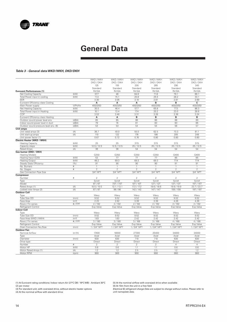
Table 3 - General data WKD/WKH, DKD/DKH
WKD / WKH WKD / WKH WKD / WKH WKD / WKH WKD / WKH WKD / WKH DKD / DKH DKD / DKH DKD / DKH DKD / DKH DKD / DKH DKD / DKH 125 155 200 265 290 340 Standard Standard Standard Standard Standard StandardEurovent Performances (1) R410A R410A R410A R410A R410A R410A
Net Cooling Capacity (kW) 37.7 46 64.6 71.6 79.1 89.1Total Power input in cooling (kW) 11.4 15.1 20.8 25.5 28.2 33.1EER 3.30 3.05 3.10 2.81 2.81 2.69Eurovent Efficiency class Cooling A A A B B C
Main Power supply V/Ph/Hz 400/3/50 400/3/50 400/3/50 400/3/50 400/3/50 400/3/50Net Heating Capacity (kW) 35.5 46.4 57.7 65.8 77.3 86.3Total Power input in Heating (kW) 10.1 13.4 17.4 20.2 23.0 26.6COP 3.53 3.46 3.31 3.26 3.36 3.24Eurovent Efficiency class Heating A A B B B B
Outdoor sound power level env. (dBA) 85 85 86 86 88 89Indoor sound power level in duct (dBA) 79 74 81 83 83 85Outdoor sound pressure level env. (6) (dBA) 53 53 54 54 56 57
Unit amps
Unit rated amps (3) (A) 36.7 40.0 55.0 62.5 73.3 81.1Unit start-up amps (A) 110 122 176 186 205 248Unit power factor (1) 0.67 0.72 0.76 0.80 0.80 0.80
Electric Heater (WKD / WKH)
Heating Capacity (kW) 25 25 37.5 37.5 37.5 37.5Capacity steps (kW) 12.5 / 12.5 12.5 / 12.5 25 / 12.5 25 / 12.5 25 / 12.5 25 / 12.5Rated Amps (A) 36 36 54 54 54 54
Gas burner (DKD / DKH)
Heating Models G250 G350 G350 G350 G400 G400Heating Input (G20) (kW) 53 77 77 77 85 85Heating Output (kW) 48.2 69.3 69.3 69.3 77.4 77.4Steady State Efficiency (%) 91 90 90 90 91 91No. Burners # 1 1 1 1 1 1No. Stages # 2 2 2 2 2 2Gas Connection Pipe Size 3/4" NPT 3/4" NPT 3/4" NPT 3/4" NPT 3/4" NPT 3/4" NPT
Compressor
Number # 2 2 2 2 2 2Type Scroll Scroll Scroll Scroll Scroll ScrollModel 6T / 6T 7.5T / 7.5T 10T / 10T 12T / 12T 13T / 13T 15T / 15TRated Amps (1) (A) 10.5 / 10.5 13.1 / 13.1 17.2 / 17.2 18.6 / 18.6 19.9 / 19.9 23.7 / 23.7Locked rotor Amps (2) (A) 87 / 87 98 / 98 142 / 142 147 / 147 158 / 158 197 / 197
Outdoor Coil
Type Wavy Wavy Wavy Wavy Wavy WavyTube Size OD (mm) 9.52 9.52 9.52 9.52 9.52 9.52Face Area (m²) 2.23 2.62 3.39 3.39 4.26 4.26Rows / Fin series # / FPF 2 / 192 2 / 192 2 / 192 2 / 192 2 / 192 2 / 192Refrigerant Control Exp.Valve Exp.Valve Exp.Valve Exp.Valve Exp.Valve Exp.Valve
Indoor Coil
Type Wavy Wavy Wavy Wavy Wavy WavyTube Size OD (mm) 9.52 9.52 9.52 9.52 9.52 9.52Face Area (WKD / WKH) (m²) 1.63 1.63 2.42 2.42 2.42 2.42Rows / Fin series # / FPF 3 / 180 3 / 180 3 / 168 3 / 168 4 / 168 4 / 168Refrigerant Control Exp.Valve Exp.Valve Exp.Valve Exp.Valve Exp.Valve Exp.ValveDrain Connection No./Size (mm) 1 / 3/4" NPT 1 / 3/4" NPT 1 / 3/4" NPT 1 / 3/4" NPT 1 / 3/4" NPT 1 / 3/4" NPT
Outdoor Fan
Nominal Airflow (m3/h) 17400 18000 27300 25400 34000 34000Type Axial Axial Axial Axial Axial AxialDiameter (mm) 630 630 710 710 630 630Drive type Direct Direct Direct Direct Direct DirectNumber # 2 2 2 2 4 4Motor HP (kW) 0.6 0.6 1.1 1.1 0.6 0.6Motor Rated Amps (1) (A) 1.2 1.2 2.5 2.5 1.2 1.2Motor RPM (rpm) 900 900 900 900 900 900
(1) At Eurovent rating conditions: Indoor return Air (27°C DB / 19°C WB) - Ambiant 35°C(2) per motor(3) For standard unit, with oversized drive, without electric heater options (4) At the nominal airflow with standard drive
(5) At the nominal airflow with oversized drive when available(6) At 10m from the unit in a free fieldElectrical & refrigerant charge Data are subject to change without notice. Please refer tounit nameplate data.
RT-PRC014-E4_1112:BAT2 30.5.2013 11:01 Page 14
General Data
15RT-PRC014-E4
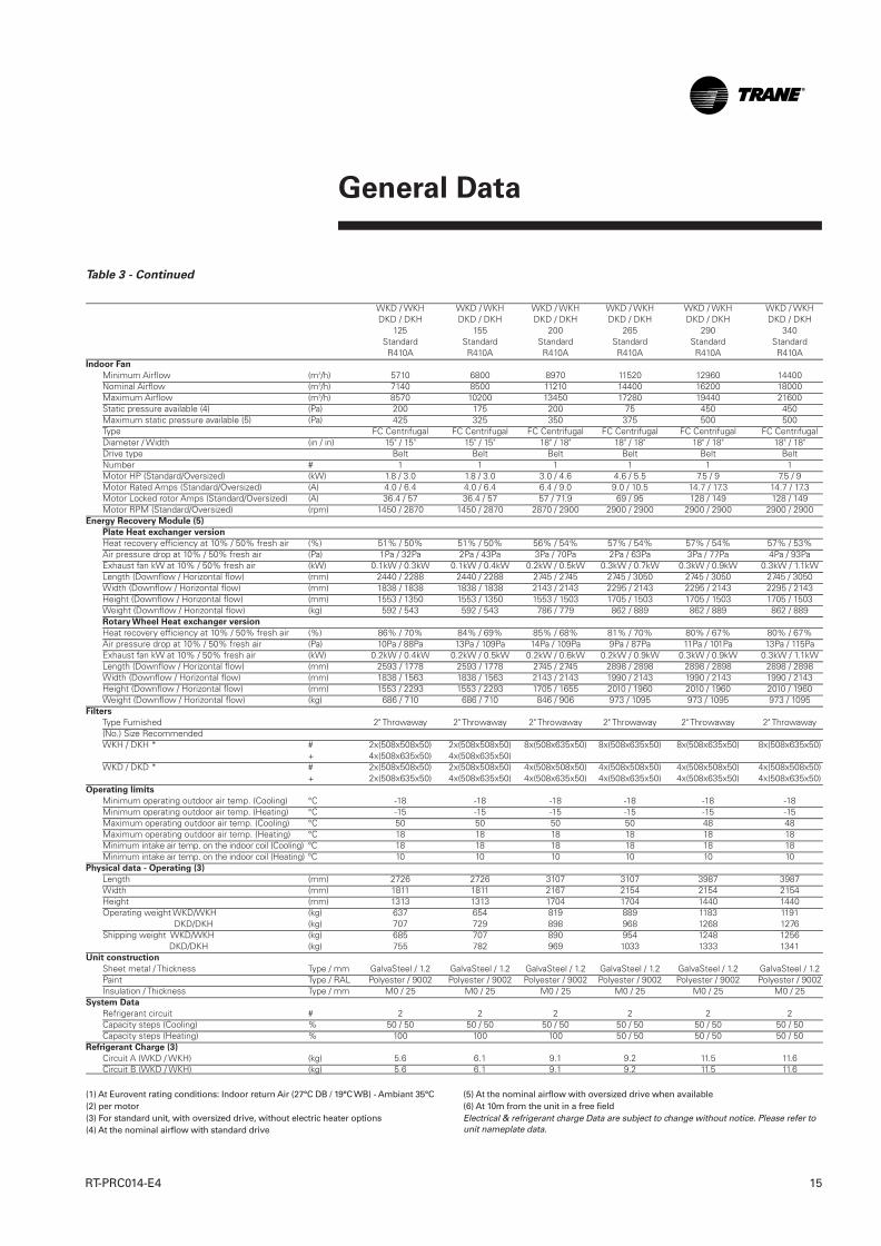
Table 3 - Continued
WKD / WKH WKD / WKH WKD / WKH WKD / WKH WKD / WKH WKD / WKH DKD / DKH DKD / DKH DKD / DKH DKD / DKH DKD / DKH DKD / DKH 125 155 200 265 290 340 Standard Standard Standard Standard Standard Standard R410A R410A R410A R410A R410A R410AIndoor Fan
Minimum Airflow (m3/h) 5710 6800 8970 11520 12960 14400Nominal Airflow (m3/h) 7140 8500 11210 14400 16200 18000Maximum Airflow (m3/h) 8570 10200 13450 17280 19440 21600Static pressure available (4) (Pa) 200 175 200 75 450 450Maximum static pressure available (5) (Pa) 425 325 350 375 500 500Type FC Centrifugal FC Centrifugal FC Centrifugal FC Centrifugal FC Centrifugal FC CentrifugalDiameter / Width (in / in) 15" / 15" 15" / 15" 18" / 18" 18" / 18" 18" / 18" 18" / 18"Drive type Belt Belt Belt Belt Belt BeltNumber # 1 1 1 1 1 1Motor HP (Standard/Oversized) (kW) 1.8 / 3.0 1.8 / 3.0 3.0 / 4.6 4.6 / 5.5 7.5 / 9 7.5 / 9Motor Rated Amps (Standard/Oversized) (A) 4.0 / 6.4 4.0 / 6.4 6.4 / 9.0 9.0 / 10.5 14.7 / 17.3 14.7 / 17.3Motor Locked rotor Amps (Standard/Oversized) (A) 36.4 / 57 36.4 / 57 57 / 71.9 69 / 95 128 / 149 128 / 149Motor RPM (Standard/Oversized) (rpm) 1450 / 2870 1450 / 2870 2870 / 2900 2900 / 2900 2900 / 2900 2900 / 2900
Energy Recovery Module (5)
Plate Heat exchanger version
Heat recovery efficiency at 10% / 50% fresh air (%) 51% / 50% 51% / 50% 56% / 54% 57% / 54% 57% / 54% 57% / 53%Air pressure drop at 10% / 50% fresh air (Pa) 1Pa / 32Pa 2Pa / 43Pa 3Pa / 70Pa 2Pa / 63Pa 3Pa / 77Pa 4Pa / 93PaExhaust fan kW at 10% / 50% fresh air (kW) 0.1kW / 0.3kW 0.1kW / 0.4kW 0.2kW / 0.5kW 0.3kW / 0.7kW 0.3kW / 0.9kW 0.3kW / 1.1kWLength (Downflow / Horizontal flow) (mm) 2440 / 2288 2440 / 2288 2745 / 2745 2745 / 3050 2745 / 3050 2745 / 3050Width (Downflow / Horizontal flow) (mm) 1838 / 1838 1838 / 1838 2143 / 2143 2295 / 2143 2295 / 2143 2295 / 2143Height (Downflow / Horizontal flow) (mm) 1553 / 1350 1553 / 1350 1553 / 1503 1705 / 1503 1705 / 1503 1705 / 1503Weight (Downflow / Horizontal flow) (kg) 592 / 543 592 / 543 786 / 779 862 / 889 862 / 889 862 / 889Rotary Wheel Heat exchanger version
Heat recovery efficiency at 10% / 50% fresh air (%) 86% / 70% 84% / 69% 85% / 68% 81% / 70% 80% / 67% 80% / 67%Air pressure drop at 10% / 50% fresh air (Pa) 10Pa / 88Pa 13Pa / 109Pa 14Pa / 109Pa 9Pa / 87Pa 11Pa / 101Pa 13Pa / 115PaExhaust fan kW at 10% / 50% fresh air (kW) 0.2kW / 0.4kW 0.2kW / 0.5kW 0.2kW / 0.6kW 0.2kW / 0.9kW 0.3kW / 0.9kW 0.3kW / 1.1kWLength (Downflow / Horizontal flow) (mm) 2593 / 1778 2593 / 1778 2745 / 2745 2898 / 2898 2898 / 2898 2898 / 2898Width (Downflow / Horizontal flow) (mm) 1838 / 1563 1838 / 1563 2143 / 2143 1990 / 2143 1990 / 2143 1990 / 2143Height (Downflow / Horizontal flow) (mm) 1553 / 2293 1553 / 2293 1705 / 1655 2010 / 1960 2010 / 1960 2010 / 1960Weight (Downflow / Horizontal flow) (kg) 686 / 710 686 / 710 846 / 906 973 / 1095 973 / 1095 973 / 1095
Filters
Type Furnished 2" Throwaway 2" Throwaway 2" Throwaway 2" Throwaway 2" Throwaway 2" Throwaway(No.) Size Recommended WKH / DKH * # 2x(508x508x50) 2x(508x508x50) 8x(508x635x50) 8x(508x635x50) 8x(508x635x50) 8x(508x635x50) + 4x(508x635x50) 4x(508x635x50) WKD / DKD * # 2x(508x508x50) 2x(508x508x50) 4x(508x508x50) 4x(508x508x50) 4x(508x508x50) 4x(508x508x50) + 2x(508x635x50) 4x(508x635x50) 4x(508x635x50) 4x(508x635x50) 4x(508x635x50) 4x(508x635x50)
Operating limits
Minimum operating outdoor air temp. (Cooling) °C -18 -18 -18 -18 -18 -18Minimum operating outdoor air temp. (Heating) °C -15 -15 -15 -15 -15 -15Maximum operating outdoor air temp. (Cooling) °C 50 50 50 50 48 48Maximum operating outdoor air temp. (Heating) °C 18 18 18 18 18 18Minimum intake air temp. on the indoor coil (Cooling) °C 18 18 18 18 18 18Minimum intake air temp. on the indoor coil (Heating) °C 10 10 10 10 10 10
Physical data - Operating (3)
Length (mm) 2726 2726 3107 3107 3987 3987Width (mm) 1811 1811 2167 2154 2154 2154Height (mm) 1313 1313 1704 1704 1440 1440Operating weight WKD/WKH (kg) 637 654 819 889 1183 1191
DKD/DKH (kg) 707 729 898 968 1268 1276Shipping weight WKD/WKH (kg) 685 707 890 954 1248 1256
DKD/DKH (kg) 755 782 969 1033 1333 1341Unit construction
Sheet metal / Thickness Type / mm GalvaSteel / 1.2 GalvaSteel / 1.2 GalvaSteel / 1.2 GalvaSteel / 1.2 GalvaSteel / 1.2 GalvaSteel / 1.2Paint Type / RAL Polyester / 9002 Polyester / 9002 Polyester / 9002 Polyester / 9002 Polyester / 9002 Polyester / 9002 Insulation / Thickness Type / mm M0 / 25 M0 / 25 M0 / 25 M0 / 25 M0 / 25 M0 / 25
System Data
Refrigerant circuit # 2 2 2 2 2 2Capacity steps (Cooling) % 50 / 50 50 / 50 50 / 50 50 / 50 50 / 50 50 / 50Capacity steps (Heating) % 100 100 100 50 / 50 50 / 50 50 / 50
Refrigerant Charge (3)
Circuit A (WKD / WKH) (kg) 5.6 6.1 9.1 9.2 11.5 11.6Circuit B (WKD / WKH) (kg) 5.6 6.1 9.1 9.2 11.5 11.6
(1) At Eurovent rating conditions: Indoor return Air (27°C DB / 19°C WB) - Ambiant 35°C(2) per motor(3) For standard unit, with oversized drive, without electric heater options (4) At the nominal airflow with standard drive
(5) At the nominal airflow with oversized drive when available(6) At 10m from the unit in a free fieldElectrical & refrigerant charge Data are subject to change without notice. Please refer tounit nameplate data.
RT-PRC014-E4_1112:BAT2 30.5.2013 11:01 Page 15
Sound Levels
RT-PRC014-E416
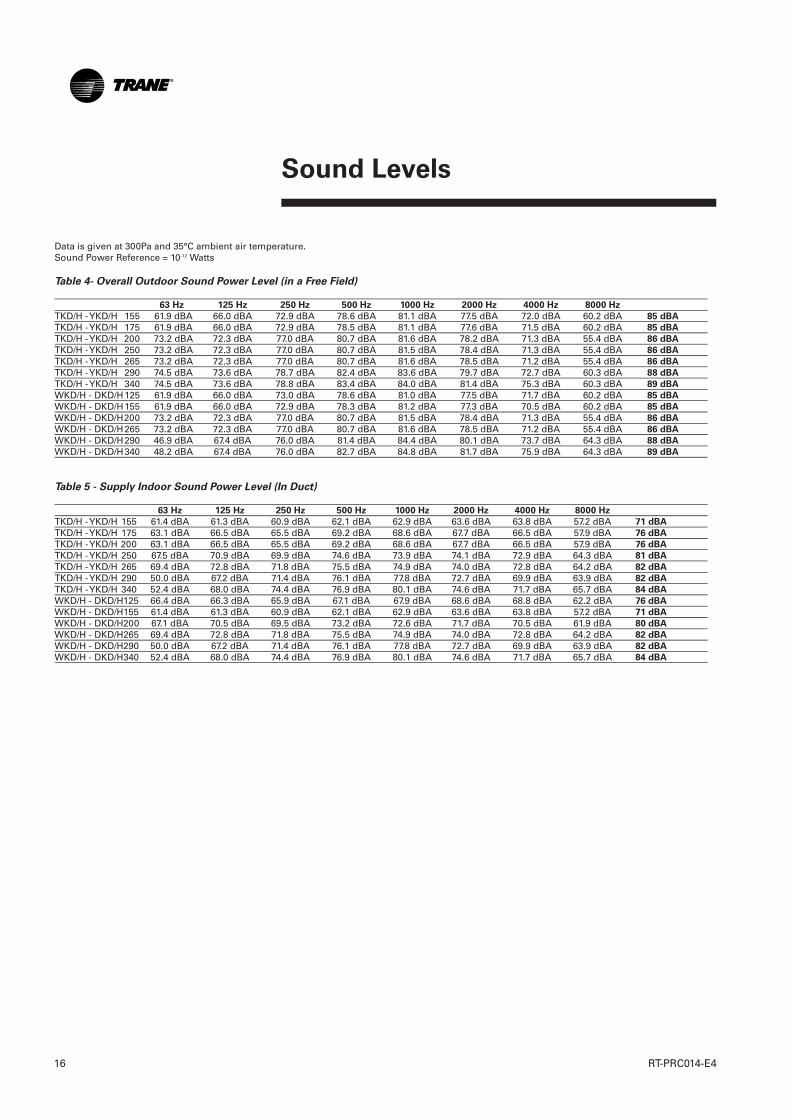
Data is given at 300Pa and 35°C ambient air temperature.Sound Power Reference = 10-12 Watts
Table 4- Overall Outdoor Sound Power Level (in a Free Field)
63 Hz 125 Hz 250 Hz 500 Hz 1000 Hz 2000 Hz 4000 Hz 8000 Hz
TKD/H - YKD/H 155 61.9 dBA 66.0 dBA 72.9 dBA 78.6 dBA 81.1 dBA 77.5 dBA 72.0 dBA 60.2 dBA 85 dBA
TKD/H - YKD/H 175 61.9 dBA 66.0 dBA 72.9 dBA 78.5 dBA 81.1 dBA 77.6 dBA 71.5 dBA 60.2 dBA 85 dBA
TKD/H - YKD/H 200 73.2 dBA 72.3 dBA 77.0 dBA 80.7 dBA 81.6 dBA 78.2 dBA 71.3 dBA 55.4 dBA 86 dBA
TKD/H - YKD/H 250 73.2 dBA 72.3 dBA 77.0 dBA 80.7 dBA 81.5 dBA 78.4 dBA 71.3 dBA 55.4 dBA 86 dBA
TKD/H - YKD/H 265 73.2 dBA 72.3 dBA 77.0 dBA 80.7 dBA 81.6 dBA 78.5 dBA 71.2 dBA 55.4 dBA 86 dBA
TKD/H - YKD/H 290 74.5 dBA 73.6 dBA 78.7 dBA 82.4 dBA 83.6 dBA 79.7 dBA 72.7 dBA 60.3 dBA 88 dBA
TKD/H - YKD/H 340 74.5 dBA 73.6 dBA 78.8 dBA 83.4 dBA 84.0 dBA 81.4 dBA 75.3 dBA 60.3 dBA 89 dBA
WKD/H - DKD/H125 61.9 dBA 66.0 dBA 73.0 dBA 78.6 dBA 81.0 dBA 77.5 dBA 71.7 dBA 60.2 dBA 85 dBA
WKD/H - DKD/H155 61.9 dBA 66.0 dBA 72.9 dBA 78.3 dBA 81.2 dBA 77.3 dBA 70.5 dBA 60.2 dBA 85 dBA
WKD/H - DKD/H200 73.2 dBA 72.3 dBA 77.0 dBA 80.7 dBA 81.5 dBA 78.4 dBA 71.3 dBA 55.4 dBA 86 dBA
WKD/H - DKD/H265 73.2 dBA 72.3 dBA 77.0 dBA 80.7 dBA 81.6 dBA 78.5 dBA 71.2 dBA 55.4 dBA 86 dBA
WKD/H - DKD/H290 46.9 dBA 67.4 dBA 76.0 dBA 81.4 dBA 84.4 dBA 80.1 dBA 73.7 dBA 64.3 dBA 88 dBA
WKD/H - DKD/H340 48.2 dBA 67.4 dBA 76.0 dBA 82.7 dBA 84.8 dBA 81.7 dBA 75.9 dBA 64.3 dBA 89 dBA
Table 5 - Supply Indoor Sound Power Level (In Duct)
63 Hz 125 Hz 250 Hz 500 Hz 1000 Hz 2000 Hz 4000 Hz 8000 Hz
TKD/H - YKD/H 155 61.4 dBA 61.3 dBA 60.9 dBA 62.1 dBA 62.9 dBA 63.6 dBA 63.8 dBA 57.2 dBA 71 dBA
TKD/H - YKD/H 175 63.1 dBA 66.5 dBA 65.5 dBA 69.2 dBA 68.6 dBA 67.7 dBA 66.5 dBA 57.9 dBA 76 dBA
TKD/H - YKD/H 200 63.1 dBA 66.5 dBA 65.5 dBA 69.2 dBA 68.6 dBA 67.7 dBA 66.5 dBA 57.9 dBA 76 dBA
TKD/H - YKD/H 250 67.5 dBA 70.9 dBA 69.9 dBA 74.6 dBA 73.9 dBA 74.1 dBA 72.9 dBA 64.3 dBA 81 dBA
TKD/H - YKD/H 265 69.4 dBA 72.8 dBA 71.8 dBA 75.5 dBA 74.9 dBA 74.0 dBA 72.8 dBA 64.2 dBA 82 dBA
TKD/H - YKD/H 290 50.0 dBA 67.2 dBA 71.4 dBA 76.1 dBA 77.8 dBA 72.7 dBA 69.9 dBA 63.9 dBA 82 dBA
TKD/H - YKD/H 340 52.4 dBA 68.0 dBA 74.4 dBA 76.9 dBA 80.1 dBA 74.6 dBA 71.7 dBA 65.7 dBA 84 dBA
WKD/H - DKD/H125 66.4 dBA 66.3 dBA 65.9 dBA 67.1 dBA 67.9 dBA 68.6 dBA 68.8 dBA 62.2 dBA 76 dBA
WKD/H - DKD/H155 61.4 dBA 61.3 dBA 60.9 dBA 62.1 dBA 62.9 dBA 63.6 dBA 63.8 dBA 57.2 dBA 71 dBA
WKD/H - DKD/H200 67.1 dBA 70.5 dBA 69.5 dBA 73.2 dBA 72.6 dBA 71.7 dBA 70.5 dBA 61.9 dBA 80 dBA
WKD/H - DKD/H265 69.4 dBA 72.8 dBA 71.8 dBA 75.5 dBA 74.9 dBA 74.0 dBA 72.8 dBA 64.2 dBA 82 dBA
WKD/H - DKD/H290 50.0 dBA 67.2 dBA 71.4 dBA 76.1 dBA 77.8 dBA 72.7 dBA 69.9 dBA 63.9 dBA 82 dBA
WKD/H - DKD/H340 52.4 dBA 68.0 dBA 74.4 dBA 76.9 dBA 80.1 dBA 74.6 dBA 71.7 dBA 65.7 dBA 84 dBA
RT-PRC014-E4_1112:BAT2 30.5.2013 11:01 Page 16

Sound Levels
17RT-PRC014-E4
Table 6 - Return Indoor Sound Power Level (In Duct) 63 Hz 125 Hz 250 Hz 500 Hz 1000 Hz 2000 Hz 4000 Hz 8000 Hz
TKD/H - YKD/H 155 63.4 dBA 60.8 dBA 56.9 dBA 63.6 dBA 66.4 dBA 61.1 dBA 56.3 dBA 48.2 dBA 71 dBATKD/H - YKD/H 175 56.1 dBA 61.0 dBA 57.0 dBA 62.2 dBA 68.1 dBA 63.7 dBA 58.5 dBA 51.4 dBA 71 dBATKD/H - YKD/H 200 56.1 dBA 61.0 dBA 57.0 dBA 62.2 dBA 68.1 dBA 63.7 dBA 58.5 dBA 51.4 dBA 71 dBATKD/H - YKD/H 250 60.5 dBA 65.4 dBA 61.4 dBA 67.6 dBA 73.4 dBA 75.1 dBA 64.9 dBA 57.8 dBA 78 dBATKD/H - YKD/H 265 62.4 dBA 67.3 dBA 63.3 dBA 68.5 dBA 74.4 dBA 70.0 dBA 64.8 dBA 57.7 dBA 78 dBATKD/H - YKD/H 290 47.8 dBA 63.5 dBA 67.6 dBA 72.3 dBA 74.3 dBA 69.7 dBA 66.9 dBA 60.9 dBA 78 dBATKD/H - YKD/H 340 50.1 dBA 64.6 dBA 70.6 dBA 73.2 dBA 76.3 dBA 71.6 dBA 68.7 dBA 62.7 dBA 80 dBAWKD/H - DKD/H125 68.4 dBA 65.8 dBA 61.9 dBA 68.6 dBA 71.4 dBA 66.1 dBA 61.3 dBA 53.2 dBA 76 dBAWKD/H - DKD/H155 63.4 dBA 60.8 dBA 56.9 dBA 63.6 dBA 66.4 dBA 61.1 dBA 56.3 dBA 48.2 dBA 71 dBAWKD/H - DKD/H200 60.1 dBA 65.0 dBA 61.0 dBA 66.2 dBA 72.1 dBA 67.7 dBA 62.5 dBA 55.4 dBA 75 dBAWKD/H - DKD/H265 62.4 dBA 67.3 dBA 63.3 dBA 68.5 dBA 74.4 dBA 70.0 dBA 64.8 dBA 57.7 dBA 78 dBAWKD/H - DKD/H290 47.8 dBA 63.5 dBA 67.6 dBA 72.3 dBA 74.3 dBA 69.7 dBA 66.9 dBA 60.9 dBA 78 dBAWKD/H - DKD/H340 50.1 dBA 64.6 dBA 70.6 dBA 73.2 dBA 76.3 dBA 71.6 dBA 68.7 dBA 62.7 dBA 80 dBA
Table 7 - Indoor Sound Level Correction with AirflowTKD/H 155 6800 m3/h - 3 dB 8500 m3/h 0 dB 10200 m3/h + 3 dBTKD/H 175 7880 m3/h - 3 dB 9850 m3/h 0 dB 11820 m3/h + 3 dBTKD/H 200 8968 m3/h - 3 dB 11210 m3/h 0 dB 13452 m3/h + 3 dBTKD/H 250 11280 m3/h - 3 dB 14100 m3/h 0 dB 16920 m3/h + 3 dBTKD/H 265 11520 m3/h - 3 dB 14400 m3/h 0 dB 17280 m3/h + 3 dBTKD/H 290 12960 m3/h - 3 dB 16200 m3/h 0 dB 19440 m3/h + 3 dBTKD/H 340 14400 m3/h - 3 dB 18000 m3/h 0 dB 21600 m3/h + 3 dBWKD/H 125 6800 m3/h - 3 dB 8500 m3/h 0 dB 10200 m3/h + 3 dBWKD/H 155 7880 m3/h - 3 dB 9850 m3/h 0 dB 11820 m3/h + 3 dBWKD/H 200 8968 m3/h - 3 dB 11210 m3/h 0 dB 13452 m3/h + 3 dBWKD/H 265 11520 m3/h - 3 dB 14400 m3/h 0 dB 17280 m3/h + 3 dBWKD/H 290 12960 m3/h - 3 dB 16200 m3/h 0 dB 19440 m3/h + 3 dBWKD/H 340 14400 m3/h - 3 dB 18000 m3/h 0 dB 21600 m3/h + 3 dB
RT-PRC014-E4_1112:BAT2 30.5.2013 11:01 Page 17
Electrical Data
RT-PRC014-E418
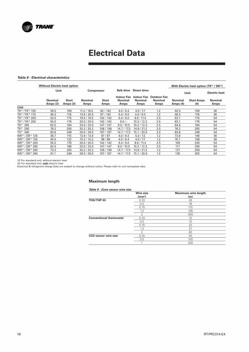
Table 8 - Electrical characteristics
Unit
TK* / YK* 155 39.5 109 11.2 / 18.5 82 / 142 4.0 / 6.4 4.9 / 7.7 1.2 42.5 109 36TK* / YK* 175 46.3 118 13.9 / 20.0 87 / 142 6.4 / 9.0 4.9 / 9.0 1.2 46.3 118 36TK* / YK* 200 52.0 175 18.5 / 18.5 142 / 142 6.4 / 9.0 8.6 / 11.4 2.5 63.1 175 54TK* / YK* 250 55.0 176 20.0 / 20.0 142 / 142 9.0 / - 10.3 / 12.2 2.5 63.1 176 54TK* 265 62.5 184 23.0 / 23.0 147 / 147 9.0 / 10.5 10.2 / 12.3 2.5 64.6 184 54TK* 290 76.2 205 25.2 / 25.2 158 / 158 14.7 / 17.3 14.9 / 21.2 2.5 76.2 205 54TK* 340 83.8 248 29.0 / 29.0 197 / 197 14.7 / 17.3 15.1 / 20.9 2.5 83.8 248 54WK* / DK* 125 36.7 110 13.9 / 13.9 87 / 87 4.0 / 6.4 5.0 / 7.2 1.2 72.8 146 36WK* / DK* 155 40.0 122 15.2 / 15.2 98 / 98 4.0 / 6.4 4.9 / 7.7 1.2 76.1 158 36WK* / DK* 200 55.0 176 20.0 / 20.0 142 / 142 6.4 / 9.0 8.6 / 11.4 2.5 109 230 54WK* / DK* 265 62.5 186 23.0 / 23.0 147 / 147 9.0 / 10.5 10.2 / 12.3 2.5 117 240 54WK* / DK* 290 73.3 205 25.2 / 25.2 158 / 158 14.7 / 17.3 14.9 / 21.2 1.2 127 259 54WK* / DK* 340 81.1 248 29.0 / 29.0 197 / 197 14.7 / 17.3 15.1 / 20.9 1.2 135 302 54
(3) For standard unit, without electric heat(4) For standard unit, with electric heatElectrical & refrigerant charge Data are subject to change without notice. Please refer to unit nameplate data.
NominalAmps (3)
StartAmps (3)
NominalAmps
StartAmps
Indoor FanNominal
Amps
Outdoor FanNominal
AmpsNominalAmps (4)
Start Amps(4)
NominalAmps
Without Electric heat option With Electric heat option (TK* / DK*)
Unit Electric heatUnit
Maximum length
Table 9 - Zone sensor wire size
Wire size Maximum wire length
(mm2) (m)
THS/THP 03 0.33 45 0.5 76 0.75 115 1.3 185 2 300Conventional thermostat 0.33 10 0.5 15 0.75 23 1.3 37 2 60CO2 sensor wire size 0.25 50 0.5 100 1 200
Compressor Belt drive Direct drive
Indoor FanNominal
Amps
RT-PRC014-E4_1112:BAT2 30.5.2013 11:01 Page 18

Dimensions and Weights
19RT-PRC014-E4
Dimensions, Weights and Clearances
Overall unit dimensions, shipping weights and operating weights are givenin the General Data tables.
Table 10 - Minimum recommended clearances
Minimum clearance
UNIT 1 2 3 4 5
TK* / YK* 155 1900 1800 1220 1000 1300TK* / YK* 175 1900 1800 1220 1000 1300TK* / YK* 200 1900 1800 1220 1000 1300TK* / YK* 250 1900 1800 1220 1000 1300TK* 265 1900 1800 1220 1000 1300TK* 290 1900 1800 1220 1000 1300TK* 340 1900 1800 1220 1000 1300WK* / DK* 125 1900 1800 1220 1000 1300WK* / DK* 155 1900 1800 1220 1000 1300WK* / DK* 200 1900 1800 1220 1000 1300WK* / DK* 265 1900 1800 1220 1000 1300WK* / DK* 290 1900 1800 1220 1000 1300WK* / DK* 340 1900 1800 1220 1000 1300
Figure 7
Weights of Factory-installed Accessories
Table 11 - Factory-installed Accessories Net Weights (kg)
WKD/DKD 125 93 220 30 15 27 14 85 49 31WKD/DKD/TKD/YKD 155 93 220 30 15 27 14 85 49 31TKD/YKD 175 93 220 30 15 27 14 85 49 24WKD/DKD/TKD/YKD 200 107 260 37 15 34 18 110 49 48TKD/YKD 250 107 260 37 15 34 18 110 49 53WKD/DKD/TKD 265 107 260 37 15 34 18 110 49 53WKD/DKD/TKD 290 107 260 37 15 34 18 110 49 80WKD/DKD/TKD 340 107 260 37 15 34 18 110 49 80WKH/DKH 125 — — 30 15 27 14 — — —WKH/DKH/TKH/YKH 155 — — 30 15 27 14 — — —TKH/YKH 175 — — 30 15 27 14 — — —WKH/DKH/TKH/YKH 200 — — 37 15 34 18 — — —TKH/YKH 250 — — 37 15 34 18 — — —WKH/DKH/TKH 265 — — 37 15 34 18 — — —WKH/DKH/TKH 290 — — 37 15 34 18 — — —WKH/DKH/TKH 340 — — 37 15 34 18 — — —
Notes :Net weight should be added to unit weight when ordering factory installed accessories.To estimate shipping weight add 2.3 kg to net weight.
UNIT
Pitc
hed
Roo
f C
urb
Pitc
hed
Roo
f C
urb
Econ
omiz
er
Man
ual
Out
side
Air
Dam
per
Mot
oriz
edO
utsi
de A
irD
ampe
r
Ele
ctric
he
ater
Hot
wat
er
coil
Dire
ct
driv
e fa
n
Filters
Table 12 - Filter arrangement
EU2 EU4
UNIT Qty Size Qty Size
TKH / TKD / YKH / YKD 155 - 175WKH / WKD / DKD / DKH 125 - 155
2x (508x508x50) 2x (498x498x40)
4x (508x635x50) 4x (500x625x50)
TKH / YKH 200-250TKH / WKH / DKH 200-265-290-340 8x (508x635x50) 8x (500x625x50)
TKD / YKD 200-250TKD / WKD / DKD 200-265-290-340
4x (508x508x50) 4x (498x498x40)
4x (508x635x50) 4x (500x625x50)
Pow
erex
haus
t fa
n
RT-PRC014-E4_1112:BAT2 30.5.2013 11:01 Page 19
Controls
RT-PRC014-E420
Equipment Protection/OperationTimings and Features
Increased reliability
Fewer components (movingelectromechanical parts); lesslikelihood of equipment down timeor failure. Standard
Proportional Integral (PI) Control
Proportional - sets corrective actionproportional to deviation fromsetpoint. Integral - fine-tunes therate of corrective action proportionalto the error (results in superiortemperature control). Standard
Built In "TEST" Mode
Aids in quick verification of systemand control operation; exercisesboth hardware and software (nospecial tools required). Standard
On Board Diagnostics
Assists with equipmenttroubleshooting if a problem shouldoccur. Standard
Low Ambient Start Timer (LAST)Function
Bypasses low pressure control whena compressor starts, eliminatingnuisance compressor lockouts.Standard
Anti Short Cycle Timer (ASCT)Function
Provides a three minute minimum"ON" time and a three minuteminimum "OFF" time forcompressors; enhances compressorreliability by ensuring proper oilreturn. Standard
Time Delay Relay (TDR) Function
Provides an incremental stagingdelay between compressors;minimizes equipment current inrushand consumption by keepingcompressors from startingsimultaneously. Standard
Built In Fan Delay Relay (FDR)
Provides custom indoor fan timingsequences for the different types ofequipment, enhancing efficiencyand reliability. Standard
Built in Evaporator Defrost Control
Provides low ambient cooling downto -18°C. Standard
Intelligent Fallback
Built-in Default Control providesadaptive operation, which allowsthe equipment to continue tooperate, and provide comfort in theevent of certain input failures. Also,allows temporary operation withouta thermostat. Standard
Emergency Stop Terminals on LowVoltage Terminal Board
Provides a convenient point todisable the equipment completelyand immediately. Standard
Lower Installation Cost
When using a Trane THS03 or THP03,control voltage wiring may be runup to five times further than anyelectromechanical system with noincrease in wire section. Example:Electromechanical System - 22 musing 0.5 mm2 wire. MicrocontrolSystem (THS/P 03) 110 m 0.5 mm2wire. Standard
Alternating Lead/Lag
During periods of part loadoperation, each compressor cyclesalternately as circuit number one,equalizing compressor wear and runtime. Enable by cutting the wire atRTRM junction number J3-8.
Demand defrost - Heat pump
Defrost only if needed; not based ontime like most other systems.Adapts to changing weatherconditions and lowers operatingcosts. Standard
RT-PRC014-E4_1112:BAT2 30.5.2013 11:01 Page 20

Controls
21RT-PRC014-E4
Heat pump Soft Start
Provides a smooth transition intoheating after defrost, minimizingnoise and compressor stressassociated with switch over.Standard
Heat pump Smart Recovery andSmart Staging
Inhibits auxiliary heat operation ifthe space is recovering adequately(0.1°C /min) with the heat pumpalone, providing considerablesavings in operating costs. Standard
Economizer Preferred Cooling
Provides fully integrated operation.Will not turn on a compressor withthe economizer, if the space isrecovering adequately with theeconomizer alone (0.1°C./minute).Allows the equipment to be utilizedin more varied applications.Standard with economizer
Features lost when using aconventional thermostat
• When a Conventional Thermostatis applied, equipment operationdiffers significantly. The basicequipment protection featuresremain intact, and the followingfeatures end benefits are lost :
• Proportional Integral (PI) control islost, equipment is controlled by athermostat or generic buildingautomation system device.
• Intelligent Fall Back is lost, if afailure occures in the devicecontrolling the equipment,operation will cease.
• Heat Pump Smart Recovery andSmart Staging is not available.Heat Pump operation becomesmore costly unless the genericcontrol applied can accomplishthis.
Field-installed ControlOptions
Zone sensors
Zone sensors are the buildingoccupants' comfort control devices.They replace the conventionalelectromechanical thermostats.Zones sensors are to be used withthe Voyager™ II units with the Microcontrol. These sensors are availablein the following options:
• THP03: Sensor, programmablesetpoint and operation modeaccording to a schedule
• TZS01: Sensor only, used whenconnected with CCP2 or Tracker™
• TZS02: Sensor and setpointadjustable thumbwheel
• THS03: Sensor, setpoint andoperation mode, unit Ledindication (mode and alarms)
From left to right: TZS01, TZS02, THS03THP03
RT-PRC014-E4_1112:BAT2 30.5.2013 11:01 Page 21
Controls
RT-PRC014-E422
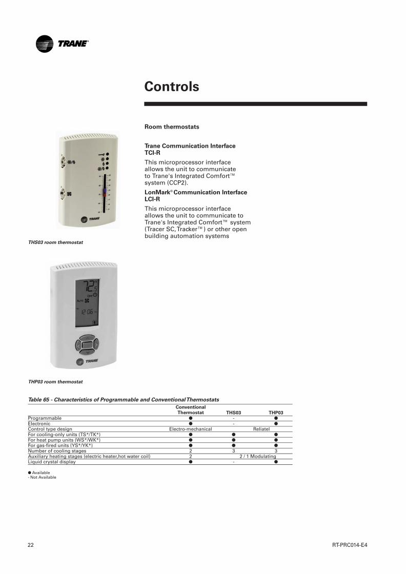
Room thermostats
Trane Communication Interface TCI-R
This microprocessor interfaceallows the unit to communicateto Trane's Integrated Comfort™system (CCP2).
LonMark® Communication InterfaceLCI-R
This microprocessor interfaceallows the unit to communicate toTrane's Integrated Comfort™ system(Tracer SC, Tracker™) or other openbuilding automation systems
Table 65 - Characteristics of Programmable and Conventional Thermostats
THS03 THP03Programmable ● - ●Electronic ● - ●Control type design Electro-mechanical ReliatelFor cooling-only units (TS*/TK*) ● ● ●For heat pump units (WS*/WK*) ● ● ●For gas-fired units (YS*/YK*) ● ● ●Number of cooling stages 2 3 3Auxiliary heating stages (electric heater,hot water coil) 2 2 / 1 ModulatingLiquid crystal display ● - ●
● Available- Not Available
THS03 room thermostat
THP03 room thermostat
ConventionalThermostat
RT-PRC014-E4_1112:BAT2 30.5.2013 11:02 Page 22
Controls
23RT-PRC014-E4
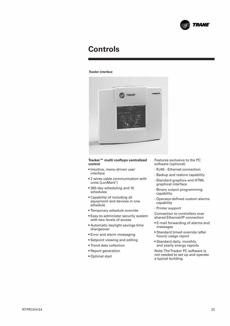
Tracker interface
Tracker™ multi rooftops centralizedcontrol
• Intuitive, menu-driven userinterface
• 2 wires cable communication withunits (LonMark®)
• 365-day scheduling and 10schedules
• Capability of including allequipment and devices in oneschedule
• Temporary schedule override
• Easy-to-administer security systemwith two levels of access
• Automatic daylight savings timechangeover
• Error and alarm messaging
• Setpoint viewing and editing
• Trend data collection
• Report generation
• Optimal start
Features exclusive to the PCsoftware (optional)
· RJ45 - Ethernet connection
· Backup and restore capability
· Standard graphics and HTMLgraphical interface
· Binary output programmingcapability
· Operator-defined custom alarmscapability
· Printer support
Connection to controllers overshared Ethernet/IP connection
• E-mail forwarding of alarms andmessages
• Standard timed override (afterhours) usage report
• Standard daily, monthly,and yearly energy reports
Note: The Tracker PC software isnot needed to set up and operatea typical building.
RT-PRC014-E4_1112:BAT2 30.5.2013 11:02 Page 23
Mechanical Specifications
RT-PRC014-E424
General
Units shall be dedicated downflowor horizontal airflow. Operatingrange shall be between 50°C and -18°C cooling as standard for allunits. All units shall be factoryassembled, internally wired, fullycharged with refrigerant, and 100percent run-tested before leavingthe factory. Wiring internal to theunit shall be colored and numberedfor simplified identification.
Unit shall be available with a mainrefrigeration circuit in cooling onlyand reversible version. Auxiliaryheat type shall be selectable: Hotwater heat, Gas heater and electricalheater in both refrigeration circuitversions.
Performance
The unit shall be certified andregistered on the Euroventcertification under RT program(http://www.eurovent-certification.com). Unit net EER shallbe class B (>2.80) or higher incooling mode except for reversibleunit of 79kW and 88kW Euroventcooling capacity .Reversible Unit netCOP shall be class B (>3.20) orhigher in Heating mode.
Casing
Unit casing shall be constructed ofzinc coated, heavy-gauge,galvanized steel. All exteriorcomponents shall be mounted in aweather resistant steel cabinet andpainted with a polyester white RAL9002 powder paint. Where top coverseams exist, they shall be doublehemmed and gasket sealed toprevent water leakage. Cabinetconstruction shall allow access forall maintenance on two sides of theunit. Service panels shall havehandles and shall be removablewhile providing a water and air tightseal. The indoor air section shallbe completely insulated with fireresistant, permanent, odorless glassfiber material, aluminum foil faced.The base of the unit shall haveprovisions for crane lifting.
Service Access ¼ locks: Standard
Electrical Control box access panelFilter access panel and supply fanaccess panel shall be locked by ¼turn locks as standard for ease ofunit service.
Filters
Unit shall be provided on standardwith 50 mm, throwaway EU3 filters.50 mm EU4 filters shall be optional.
Compressors
All units shall have scroll typecompressors. Compressor shall bedirect-drive, hermetic with self-lubrication. Motor shall be suctiongas-cooled and shall have a voltageutilization range of plus or minus10 percent of unit nameplatevoltage. Internal temperature andcurrent sensitive motor overloadsshall be included for maximumprotection. Each compressor shallbe protected by external dischargetemperature thermostat, windingtemperature thermostat and reverserotation/phase loss protection. Eachcompressor shall have crankcaseheaters installed, properly sized tominimize the amount of liquidrefrigerant present in the oil sumpduring off cycles. All scrollcompressors shall be protected withphase monitoring protection.
Refrigerant Circuits
The unit shall be operating withR410A HFC-based refrigerant. Eachrefrigerant circuit shall haveindependent thermostatic expansiondevices, service pressure ports andrefrigerant line filter driers factory-installed as standard. An area shallbe provided for replacement suctionline driers. Refrigeration circuit shallbe protected against refrigerant leakby a low pressure switch. Servicevalves shall be provided as standardand located on low pressure andhigh pressure side of therefrigeration piping.
RT-PRC014-E4_1112:BAT2 30.5.2013 11:02 Page 24

Mechanical Specifications
25RT-PRC014-E4
Evaporator and Condenser Coils
Condenser coils shall have 3/8"(10 mm) copper tubes mechanicallybonded to lanced aluminum platefins. Evaporator coils shall be 3/8"(13 mm) internally finned coppertubes mechanically bonded to highperformance aluminum plate fins.All coils shall be leak tested at thefactory to ensure pressure integrity.All coils shall be leak tested to2.1 MPa and pressure tested to4.5 MPa. All evaporator coils shallbe of intermingled configuration.Sloped condensate drain pans arestandard. Indoor coil shall beprotected as optional by an ant frostthermostat.
Outdoor Fans
The outdoor fans shall be directdrive, statically and dynamicallybalanced, draw-through in thevertical discharge position. The fanmotors shall be permanentlylubricated and shall have built-inthermal overload protection.
Indoor Fan
Units shall have belt driven, forwardcurved centrifugal fans with variablediameter motor sheaves. All motorsshall be protected from overload.
Controls
Unit shall be completely factorywired with necessary controls andterminal block for power wiring.Units shall provide an externallocation for mounting fuseddisconnect device. Unit controllershall be provided for all 24 voltcontrol functions. The residentcontrol algorithms shall make allheating, cooling and/or ventilatingdecisions in response to electronicsignals from sensors measuringindoor and outdoor temperature.The control algorithm maintainsaccurate temperature control,minimizes drift from set point andprovides better building comfort.
Unit controller shall provide anti-short cycle timing and time delaybetween compressors to provide ahigher level of machine protection.Heat pump unit shall managedefrost cycles based on demanddefrost logic.
Unit shall be powered by400V/3/50Hz supply (withoutneutral) on a single point of powerconnection.
Ventilation Override
Shall allow a binary input from thefire/life safety panel to cause theunit to override standard operationand assume one of two factorypreset ventilation sequences,exhaust or pressurization. The twosequences shall be selectable basedopen a binary select input.
Phase Monitoring Relay: Standard
Unit shall detect phase loss, phasereversal from main power supply.In case of fault, the unit shall stop.
Through-The-Base ElectricalProvision: Standard
An electrical service entrance shallbe standard which allows access toroute all high and low voltageelectrical wiring inside the curb,through the bottom (vertically) andthrough the side (Horizontally) ofthe outdoor section of the unit andinto the control box area.
Disconnect Switch: Optional
A factory installed disconnect switchwith external handle shall bemounted inside the unit control box.
RT-PRC014-E4_1112:BAT2 30.5.2013 11:02 Page 25
Mechanical Specifications
RT-PRC014-E426
Options and Accessories
Manual Fresh Air Damper
A manually controllable outside airdamper shall be adjustable for up to25 percent outside air. Manualdamper is set at desired position atunit start up.
Motorized Fresh Air damper
This option shall be factory mounted.Outdoor air rate shall be adjustablefrom 0 to 50 percent. Once set,outdoor air dampers shall open toset position when indoor fan starts.The damper shall close to the fullclosed position when indoor fanshuts down.
Economizer - Downflow
Economizer shall be factoryinstalled. The assembly includes:fully modulating 0-100 percentmotor and dampers, minimumposition setting, preset linkage,wiring harness, and differentialenthalpy control. It shall be providedwith barometric relief damper.Barometric relief damper shalldeliver a space pressureequalization and be gravity closingto prohibit entrance of outside airduring the equipment "off" cycle.
Economizer - Horizontal flow
Economizer shall be factoryinstalled. The assembly includes:fully modulating 0-100 percentmotor and dampers, minimumposition setting, preset linkage,wiring harness, and differentialenthalpy control.
Power Exhaust Fan
Power exhaust shall be optionalwith the downflow economizer.It shall be available as a factoryinstalled option on all units size.It shall assist the barometric reliefdamper in maintaining buildingpressurization.
Remote Potentiometer
A remote potentiometer shall beavailable to remotely adjust the unitfresh air damper minimum position.
CO2 Sensor
This accessory shall be compatiblewith motorized Fresh air damperand economizer options. It shallmeasure CO2 concentration in orderto increase or decrease the fresh airamount in the building.
Direct driven Variable Frequency fan:Optional
VFDs shall be factory installed andtested to provide supply fan motorspeed modulation. The VFD shallreceive speed reference from theunit controller based upon supplyzone heating/cooling demand andshall cause the drive to accelerate ordecelerate as required to maintainthe zone temperature setpoint. Thefan coupling shall be direct typewith the motor shaft. Units shallhave a soft rubber direct couplingbetween centrifugal fans and motor.Motor, fan and VFD shall beindividually replaced in case ofmaintenance operation.
Fan Fail Switch
This option allows checks for supplyfan pressure. The fan failure switchwill stop all unit functions andreport Service alarm on the zonesensor module or Buildingmanagement system.
Clogged Filter Switch
This option allows for individualdirty filter indication. The switch willlight the Service LED on the zonesensor and will allow continued unitoperation.
Smoke Detector
This option shall trip off in case ofpresence of smoke in the supplyside of the unit and shall close thereturn air damper, if any, and stopthe unit.
RT-PRC014-E4_1112:BAT2 30.5.2013 11:02 Page 26
Mechanical Specifications
27RT-PRC014-E4
Phase Monitoring Relay
The phase monitoring relay shalldetect phase loss, phase reversaland phase imbalance from mainpower supply. In case of fault,the unit must stop.
Black Epoxy Fin Coating
An optional coil corrosion resistantcoating shall protect indoor andoutdoor aluminum fins.
Fire thermostats
Field installed manually resettablehigh temperature thermostats shallprovide input to the unit controls toshut down the system if thetemperature sensed at the returnis 57°C or at the discharge 115°C.
Roof Curb - Downflow
The roof curb shall be designed tomate with the downflow unit andprovide support and watertightinstallation when installed properly.
The roof curb design shall allowfield fabricated rectangularsupply/return ductwork to beconnected directly to the curb.
Curb shall be shipped knockeddown for field assembly.
Adjustable Roof Curb
This factory assembled accessoryis adjustable on site and allowscorrection of the slope of the roofup to 5%.
Hot Water Coil
This option shall be factorymounted and placed in thedischarge section. It shall beshipped with one 3-way valve, 0 to100% modulating built-in controland freezestat protection. If needed,on reversible unit, hot water coilshall be selected as first source ofheat before mechanical heating.
Electric Heaters
Electric heat shall be available forfactory installation within basic unit.Electric heater elements shall beconstructed of heavy-duty nickelchromium elements we connectedfor 380 and 415 volt. Staging shallbe achieved through the unitcontroller. Each heater package shallhave automatically reset high limitcontrol operating through heatingelement contactors. All heaters shallbe individually fused from factory,where required.
Gas Heater
The heating section shall have adrum and tube heat exchanger(s)design using corrosion resistantsteel components. A forcedcombustion blower shall supplypremixed fuel to a single burnerignited by a pilotless hot surfaceignition system. In order to providereliable operation, a negativepressure gas valve shall be usedthat requires blower operation toinitiate gas flow. On an initial call forheat, the combustion blower shallpurge the heat exchanger(s)45 seconds before ignition. Afterthree unsuccessful ignitionattempts, the entire heating systemshall be locked out until manuallyreset at the thermostat. Units shallbe suitable for use with natural gasor propane (field installed kit). Allunits shall have two stage heating.
Burner of 48kW and 70kW shall havea no emissions of CO (< 0.001%) andNOx emission below 30ppm (class 5according to the requirements ofStandard EN483). Burner of 77kWshall have a no emissions of CO(< 0.001%) and NOx emission below50ppm (class 4 according to therequirements of Standard EN483)
RT-PRC014-E4_1112:BAT2 30.5.2013 11:02 Page 27
Energy Recovery Module - General
Heat recovery should include directdriven exhaust fan. Fan speedshould be adjusted by a separatefrequency drive according to freshair flow in order to maintainbuilding pressurization.
Fresh air flow shall be filtered beforeentering in the heat exchanger inorder to prevent clogging on thefresh air side.
When free cooling is needed, energyrecovery should be by-passed toavoid heat exchange on the freshflow entering into the building.
Energy Recovery Module - Plateheat exchanger version
Energy recovery module shouldhave a total efficiency of 51% orhigher at -5°C outdoor, 19°C indoorand 30% fresh air rate. Module shallbe equipped with freeze monitoringpressure switch that initiate defrostcycle when exchanger in clogged byfrost in winter application
Energy Recovery Module - Heatwheel version
Energy recovery should have a totalefficiency of 64% or higher at -5°Coutdoor, 19°C indoor and 30% freshair rate. Fresh air and exhaust airflow shall be filtered before enteringin the heat exchanger in order toprevent exchanger clogging.
Thermostats and Zone Sensors
The thermostats and zone sensorsshall be provided to interface withthe ReliaTel® unit controls and shallbe available in either manual,automatic programmable with nightsetback, with system malfunctionlights or remote sensor options.
Communication Interface (TCI-R)
ReliaTel®Trane CommunicationInterface (TCI) shall be provided tointerface with the Trane IntegratedComfort™ System and shall beavailable as a field or factory-installed. The TCI-R shall allowcontrol and monitoring of therooftop unit via a two wirescommunication link.
Trane Modbus CommunicationInterface (PIC)
Modbus Communication Interface(PIC) shall be provided to interfacewith the Trane Integrated Comfort™System and shall be available field-installed. The PIC shall allow controland monitoring of the rooftop unitvia a two wire communication linkand Modbus protocol.
LonTalk® Communication Interface(LCI-R)
The field or factory-installedReliaTel® LonTalk CommunicationInterface (LCI-R) will be provided tointerface with the Trane IntegratedComfort™ System or LonTalk®
capable third party buildingmanagement networks. The LCI-Rwill allow control and monitoringof the rooftop unit via a two wirescommunication link.
Tracker® Multi rooftop centralizedmanagement control
Simple Building Control
The Tracker building automationsystem (BAS) is a heating,ventilating, and air conditioning(HVAC) energy management systemfor small- to medium-size buildings.It provides reliable, centralizedcontrol for HVAC equipment,managing it for optimal comfort andefficiency.
Mechanical Specifications
RT-PRC014-E428
RT-PRC014-E4_1112:BAT2 30.5.2013 11:02 Page 28
The Tracker BAS includes a controllerwith a liquid crystal display (LCD)touch screen. The Tracker BAS alsoincludes optional Windows-basedsoftware that can be installed on a PCworkstation. Connection betweenTracker BAS and PC software ispossible through modem, directserial RS232 link or Ethernet IPcommunication.
The Tracker BAS is LonMark®
compliant. It communicates withsupported devices over a TraneComm5 link. The Trane Comm5link is a communication link thatimplements LonTalk and a LonTalkFTT-10A network. LonTalk is anopen, industry-standard protocol.
The touch screen provide an easy-to-use visual interface. The interfacesenable an operator to set up andchange HVAC operating parametersand collect and display buildinginformation.
The Tracker BAS offer these features:
• Intuitive LCD touch screen userinterface
• 365-day scheduling and10 schedules
• Capability of including allequipment and devices in oneschedule
• Temporary schedule override
• Easy-to-administer security systemwith two levels of access
• Automatic daylight savings timechangeover
• Error and alarm messaging
• Setpoint viewing and editing
• Auto configuration
When Trane Comm5 devices areused as a system and power isapplied to the controller, the TrackerBAS automatically configures itself.It is no longer necessary to programthe building management system.During auto configuration, thecontroller:
• Discovers all devices on thecommunication link
• Loads all devices into a non-erasable memory database
• Turns to On or Occupied alldiscovered HVAC equipmentexcept the binary output relays ofthe Tracer MP503 I/O module,which remain de-energized (Off)
Mechanical Specifications
29RT-PRC014-E4
RT-PRC014-E4_1112:BAT2 30.5.2013 11:02 Page 29

Reliatel® Unit controller OriginatedData
• Unit operating mode
• Unit failure status
- Cooling failure
- Heating failure
- Emergency service stopindication
- Supply fan proving
- Timed override activation
- High temperature thermostatstatus
• Zone temperature
• Supply air temperature
• Cooling status (all stages)
• Stage activated or not
• Stage locked out by Reliatel
• HPC status for that stage
• Compressor disable inputs
• Heating status
• Number of stages activated
• High temperature limit status
• Economizer status
• Requested minimum position
• Damper position
• Dry bulb/enthalpy input status
• Outside air temperature
• Outside relative humidity
• Sensor Failure
- Humidity sensor
- Outdoor Air Temperature sensor
- Supply Air Temperature sensor
- Return Air Temperature sensor
- Zone temperature sensor
- Mode input
- Cooling/heating setpoint fromsensors
- Unit mounted potentiometer
• Unit Configuration data
- Gas or electric heat
- Economizer present
• Local setpoint
• Local mode setting
• Clogged filter service indicator
• CO2 setpoint
• CO2 value
Building Management Systemcommunication Originated Data
• Command operating mode
• Host controllable functions:
- Supply fan
- Economizer
- Cooling stages enabled
- Heating stages enabled
- Emergency shutdown
• Minimum damper position
• Heating setpoint
• Cooling setpoint
• Supply air temperingenable/disable
• Slave mode (CV only)
• Tracer/Local operation
• Daytime warm-up enable/disable
• Power exhaust setpoint
Mechanical Specifications
RT-PRC014-E430
RT-PRC014-E4_1112:BAT2 30.5.2013 11:02 Page 30

31RT-PRC014-E4
RT-PRC014-E4_1112:BAT2 30.5.2013 11:02 Page 31

© 2013 Trane All rights reservedRT-PRC014-E4_0513Supersedes RT-PRC014-E4_1112
We are committed to using environmentallyconscious print practices that reduce waste.
Trane optimizes the performance of homes and buildings around the world. A business of Ingersoll Rand, the leaderin creating and sustaining safe, comfortable and energy efficient environments, Trane offers a broad portfolio ofadvanced controls and HVAC systems, comprehensive building services, and parts. For more information, visitwww.Trane.com.
Trane has a policy of continuous product and product data improvement and reserves the right to change design and specifications without notice.
RT-PRC014-E4_1112:BAT2 30.5.2013 11:02 Page 32