vpc (variable pitch compression) screw system · introduction the vpc (variable pitch compression)...
TRANSCRIPT
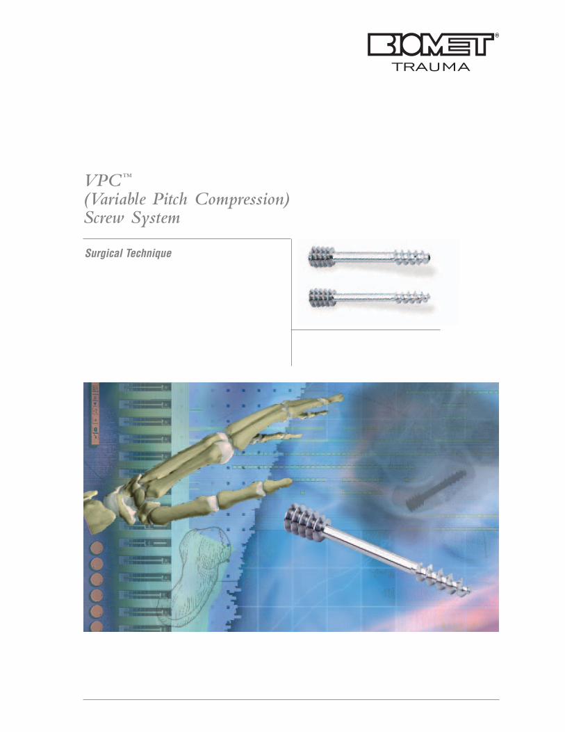
Surgical Technique
VPC™
(Variable Pitch Compression)Screw System
Contents
Introduction ................................................ Page 1
Product Description .................................... Page 2
Indications .................................................. Page 3
Classification Of Scaphoid Fractures .......... Page 4
Surgical TechniquePatient Preparation .................................. Page 6Guide Wire Placement ............................ Page 8VPC Screw Insertion (Mini Screw) .......... Page 9Closure And Post Operative Care ............ Page 10Percutaneous And ArthroscopicallyAssisted Techniques ................................ Page 11
Mini VPC Screws And Instruments ............ Page 12
Micro VPC Screws And Instruments .......... Page 13
VPC Screw System: Universal Instruments ................................ Page 14
References ................................................ Page 16
Further Information .................................... Page 17
Introduction
The VPC (Variable Pitch Compression) Screw is a stainless
steel variable pitch screw designed to provide stable
fixation and compression of small bone fragments where a
protrusive screw head is undesirable. The combination of a
small diameter and non-threaded central portion minimizes
the amount of bone sacrificed during a surgical procedure.
The VPC Screw is indicated for fusions, fractures or
osteotomies of the upper and lower extremities.
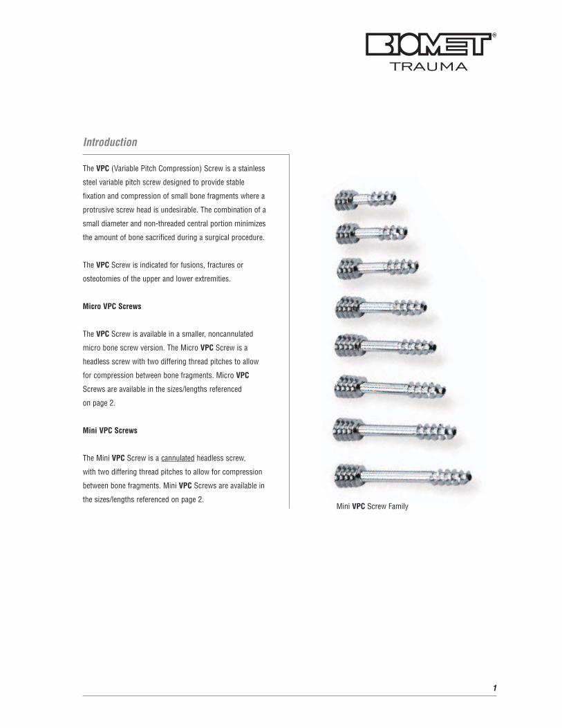
Micro VPC Screws
The VPC Screw is available in a smaller, noncannulated
micro bone screw version. The Micro VPC Screw is a
headless screw with two differing thread pitches to allow
for compression between bone fragments. Micro VPC
Screws are available in the sizes/lengths referenced
on page 2.
Mini VPC Screws
The Mini VPC Screw is a cannulated headless screw,
with two differing thread pitches to allow for compression
between bone fragments. Mini VPC Screws are available in
the sizes/lengths referenced on page 2.
1
Mini VPC Screw Family
Product Description
2
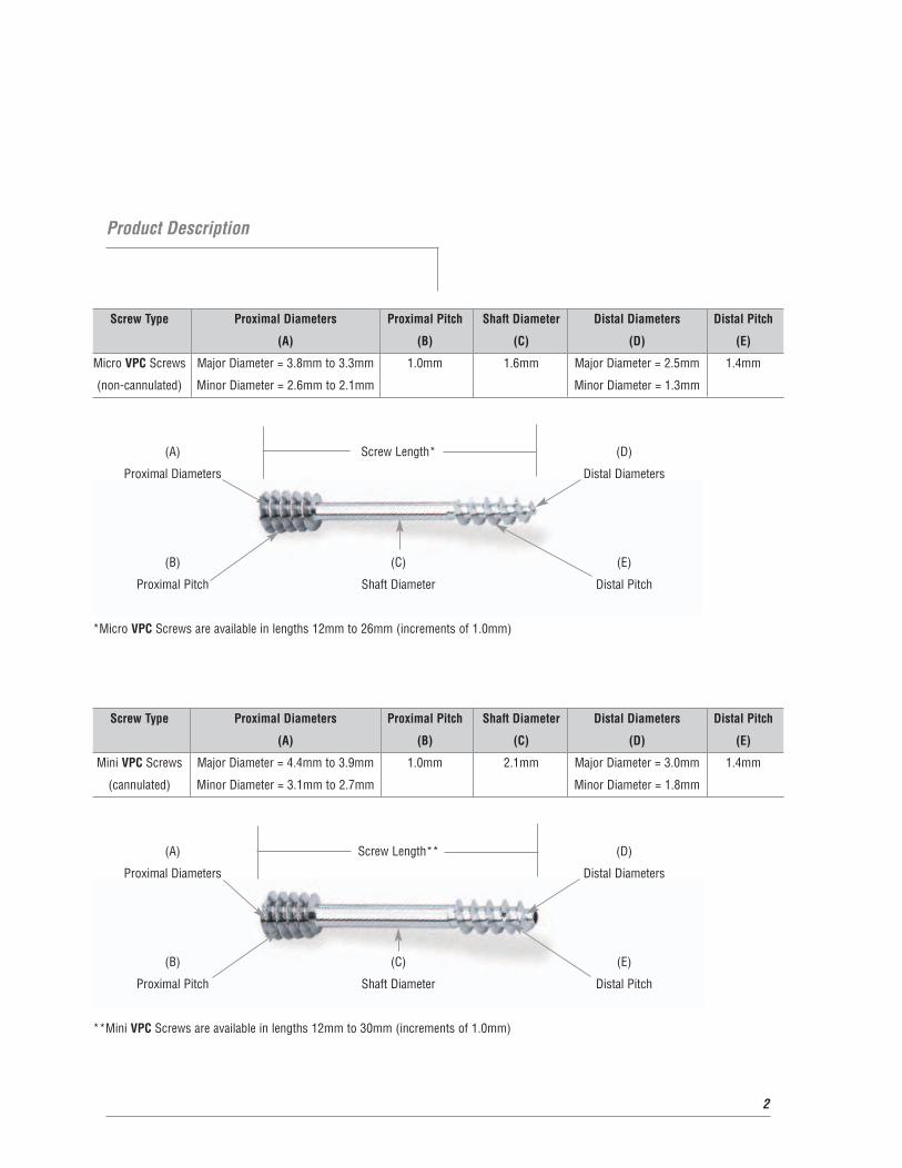
Screw Type Proximal Diameters Proximal Pitch Shaft Diameter Distal Diameters Distal Pitch
(A) (B) (C) (D) (E)
Mini VPC Screws Major Diameter = 4.4mm to 3.9mm 1.0mm 2.1mm Major Diameter = 3.0mm 1.4mm
(cannulated) Minor Diameter = 3.1mm to 2.7mm Minor Diameter = 1.8mm
(A) Screw Length** (D)
Proximal Diameters Distal Diameters
(B) (C) (E)
Proximal Pitch Shaft Diameter Distal Pitch
**Mini VPC Screws are available in lengths 12mm to 30mm (increments of 1.0mm)
Screw Type Proximal Diameters Proximal Pitch Shaft Diameter Distal Diameters Distal Pitch
(A) (B) (C) (D) (E)
Micro VPC Screws Major Diameter = 3.8mm to 3.3mm 1.0mm 1.6mm Major Diameter = 2.5mm 1.4mm
(non-cannulated) Minor Diameter = 2.6mm to 2.1mm Minor Diameter = 1.3mm
(A) Screw Length* (D)
Proximal Diameters Distal Diameters
(B) (C) (E)
Proximal Pitch Shaft Diameter Distal Pitch
*Micro VPC Screws are available in lengths 12mm to 26mm (increments of 1.0mm)
Indications
Fixation of scaphoid fractures and nonunions,
osteotomies and fractures of the carpus and hand or
foot, intra-articular fractures, osteochondral fractures,
and small joint arthrodesis.
The biomechanical and vascular characteristics
of the scaphoid result in a relatively high incidence
of complications associated with fracture. Anatomic
reduction and stable internal fixation of displaced
scaphoid fractures has been shown to increase the
rate of union and limit the sequelae associated with
these difficult fractures. Fixation of nondisplaced
unstable fractures has also been advocated in some
clinical situations to limit the need for immobilization
enhancing a more rapid functional recovery. In the setting
of an established scaphoid nonunion, open reduction in
conjunction with cancellous or cortico-cancellous bone
grafting and internal fixation has been shown to result in a
high rate of union restoring intercarpal relationships in an
attempt to prevent or delay degenerative changes.
By avoiding the use of plaster or fiberglass, early
(protected) joint motion is possible. There appears
to be accelerated bone healing which could lead to a
more rapid functional recovery. The complications of
plaster, i.e. joint stiffness, osteoporosis, and muscle
atrophy are avoided. Internal fixation using the VPC
Screw is indicated in the treatment of all acute, unstable
fractures (Type B) of the scaphoid, or whenever prolonged
plaster or fiberglass immobilization is contraindicated.
Similarly, internal fixation has proven to be invaluable as an
adjunct to bone grafting for scaphoid nonunion (Type C).
3
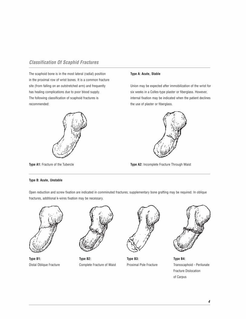
The scaphoid bone is in the most lateral (radial) position
in the proximal row of wrist bones. It is a common fracture
site (from falling on an outstretched arm) and frequently
has healing complications due to poor blood supply.
The following classification of scaphoid fractures is
recommended:
Type A1: Fracture of the Tubercle
Type A: Acute, Stable
Union may be expected after immobilization of the wrist for
six weeks in a Colles-type plaster or fiberglass. However,
internal fixation may be indicated when the patient declines
the use of plaster or fiberglass.
Type A2: Incomplete Fracture Through Waist
Classification Of Scaphid Fractures
4
Type B: Acute, Unstable
Open reduction and screw fixation are indicated in comminuted fractures; supplementary bone grafting may be required. In oblique
fractures, additional k-wires fixation may be necessary.
Type B1: Type B2: Type B3: Type B4:
Distal Oblique Fracture Complete Fracture of Waist Proximal Pole Fracture Transscaphoid - Perilunate
Fracture Dislocation
of Carpus
5
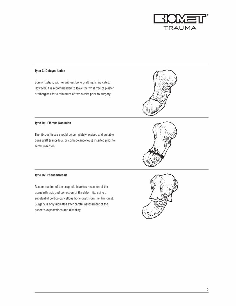
Type C: Delayed Union
Screw fixation, with or without bone grafting, is indicated.
However, it is recommended to leave the wrist free of plaster
or fiberglass for a minimum of two weeks prior to surgery.
Type D1: Fibrous Nonunion
The fibrous tissue should be completely excised and suitable
bone graft (cancellous or cortico-cancellous) inserted prior to
screw insertion.
Type D2: Pseudarthrosis
Reconstruction of the scaphoid involves resection of the
pseudarthrosis and correction of the deformity, using a
substantial cortico-cancellous bone graft from the iliac crest.
Surgery is only indicated after careful assessment of the
patient’s expectations and disability.
Patient Preparation
The patient is positioned supine with a radiolucent hand
table. General or regional anesthesia is recommended.
A proximal pneumatic tourniquet is utilized and the arm is
prepped and draped in the usual orthopedic fashion. If the
need for an iliac crest bone graft is anticipated, the chosen
anterior iliac crest is prepped and draped. Exposure may
be facilitated by a small bump placed beneath the hip.
Volar Approach
The majority of displaced scaphoid fractures are
approached volarly. This facilitates fracture visualization
and reduction without risk of compromising the dorsal
vasculature. The volar approach also allows for the
correction of the classic apex dorsal or “humpback”
deformity associated with scaphoid nonunions in addition
to allowing optimal bone graft placement.
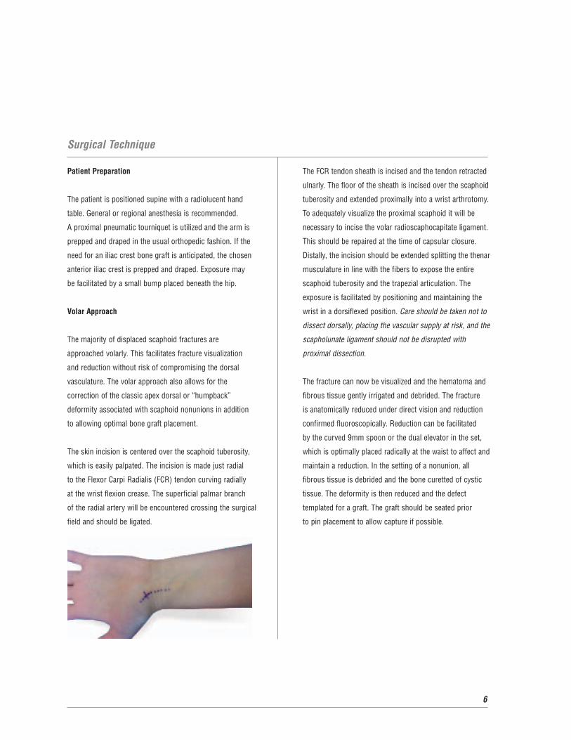
The skin incision is centered over the scaphoid tuberosity,
which is easily palpated. The incision is made just radial
to the Flexor Carpi Radialis (FCR) tendon curving radially
at the wrist flexion crease. The superficial palmar branch
of the radial artery will be encountered crossing the surgical
field and should be ligated.
Surgical Technique
6
The FCR tendon sheath is incised and the tendon retracted
ulnarly. The floor of the sheath is incised over the scaphoid
tuberosity and extended proximally into a wrist arthrotomy.
To adequately visualize the proximal scaphoid it will be
necessary to incise the volar radioscaphocapitate ligament.
This should be repaired at the time of capsular closure.
Distally, the incision should be extended splitting the thenar
musculature in line with the fibers to expose the entire
scaphoid tuberosity and the trapezial articulation. The
exposure is facilitated by positioning and maintaining the
wrist in a dorsiflexed position. Care should be taken not to
dissect dorsally, placing the vascular supply at risk, and the
scapholunate ligament should not be disrupted with
proximal dissection.
The fracture can now be visualized and the hematoma and
fibrous tissue gently irrigated and debrided. The fracture
is anatomically reduced under direct vision and reduction
confirmed fluoroscopically. Reduction can be facilitated
by the curved 9mm spoon or the dual elevator in the set,
which is optimally placed radically at the waist to affect and
maintain a reduction. In the setting of a nonunion, all
fibrous tissue is debrided and the bone curetted of cystic
tissue. The deformity is then reduced and the defect
templated for a graft. The graft should be seated prior
to pin placement to allow capture if possible.
7
Dorsal Approach
Proximal pole fractures and non-displaced waist fractures
are best approached dorsally. The proximal pole is localized
fluoroscopically and a 1.5-2.0cm incision is placed distal
to Lister’s tubercle. Dissection is carried through the
subcutaneous tissues with care to protect branches of the
superficial radial nerve.
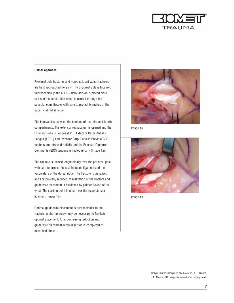
The interval lies between the tendons of the third and fourth
compartments. The extensor retinaculum is opened and the
Extensor Pollicis Longus (EPL), Extensor Carpi Radialis
Longus (ECRL) and Extensor Carpi Radialis Brevis (ECRB)
tendons are retracted radially and the Extensor Digitorum
Communis (EDC) tendons retracted ulnarly (Image 1a).
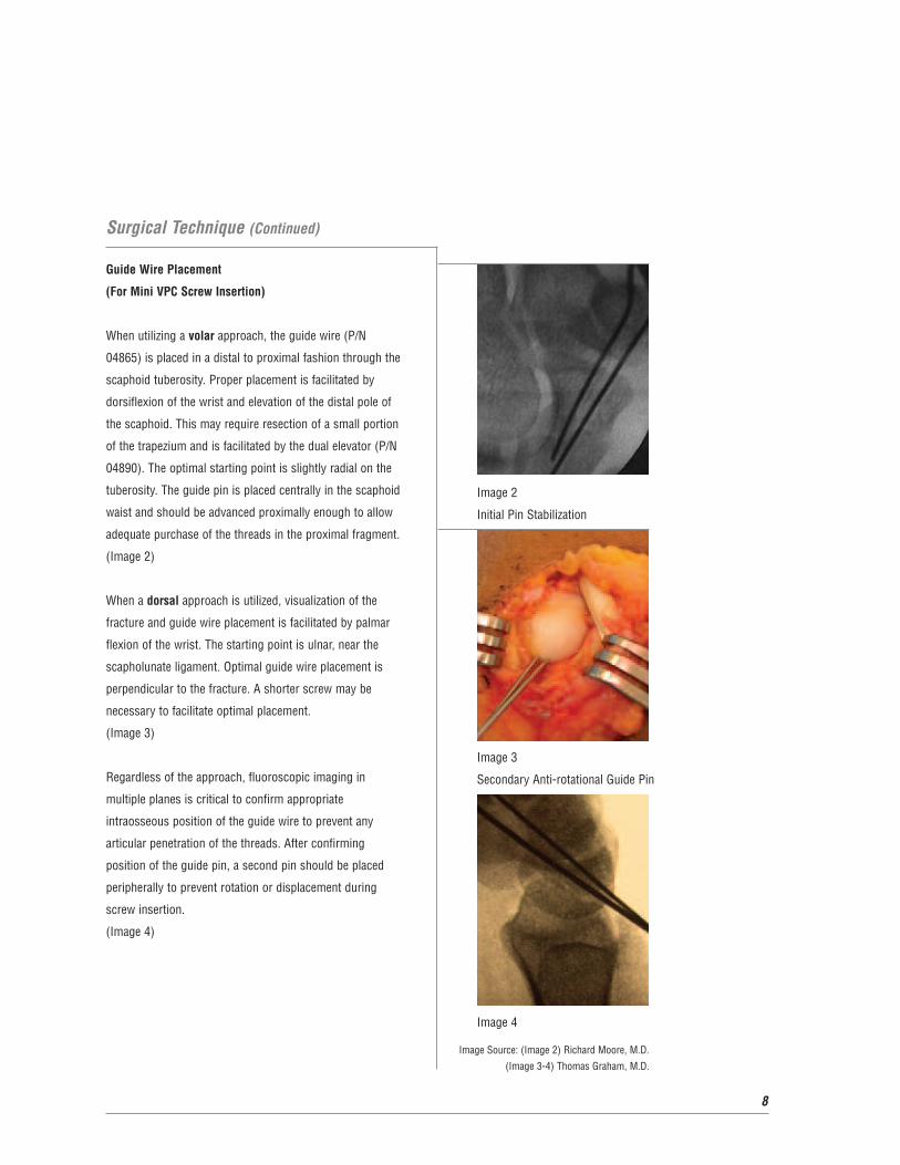
The capsule is incised longitudinally over the proximal pole
with care to protect the scapholunate ligament and the
vasculature of the dorsal ridge. The fracture is visualized
and anatomically reduced. Visualization of the fracture and
guide wire placement is facilitated by palmar flexion of the
wrist. The starting point is ulnar near the scapholunate
ligament (Image 1b).
Optimal guide wire placement is perpendicular to the
fracture. A shorter screw may be necessary to facilitate
optimal placement. After confirming reduction and
guide wire placement screw insertion is completed as
described above.
Image 1a
Image 1b
Image Source: (Image 1a-1b) Freeland, A.E., Bloom,
H.T., Moore, J.B., Wegener. www.hand-surgery.co.uk
8
Surgical Technique (Continued)
Guide Wire Placement
(For Mini VPC Screw Insertion)
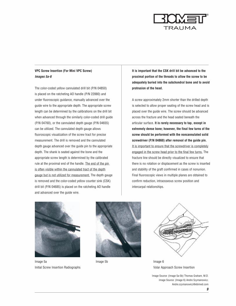
When utilizing a volar approach, the guide wire (P/N
04865) is placed in a distal to proximal fashion through the
scaphoid tuberosity. Proper placement is facilitated by
dorsiflexion of the wrist and elevation of the distal pole of
the scaphoid. This may require resection of a small portion
of the trapezium and is facilitated by the dual elevator (P/N
04890). The optimal starting point is slightly radial on the
tuberosity. The guide pin is placed centrally in the scaphoid
waist and should be advanced proximally enough to allow
adequate purchase of the threads in the proximal fragment.
(Image 2)
When a dorsal approach is utilized, visualization of the
fracture and guide wire placement is facilitated by palmar
flexion of the wrist. The starting point is ulnar, near the
scapholunate ligament. Optimal guide wire placement is
perpendicular to the fracture. A shorter screw may be
necessary to facilitate optimal placement.
(Image 3)
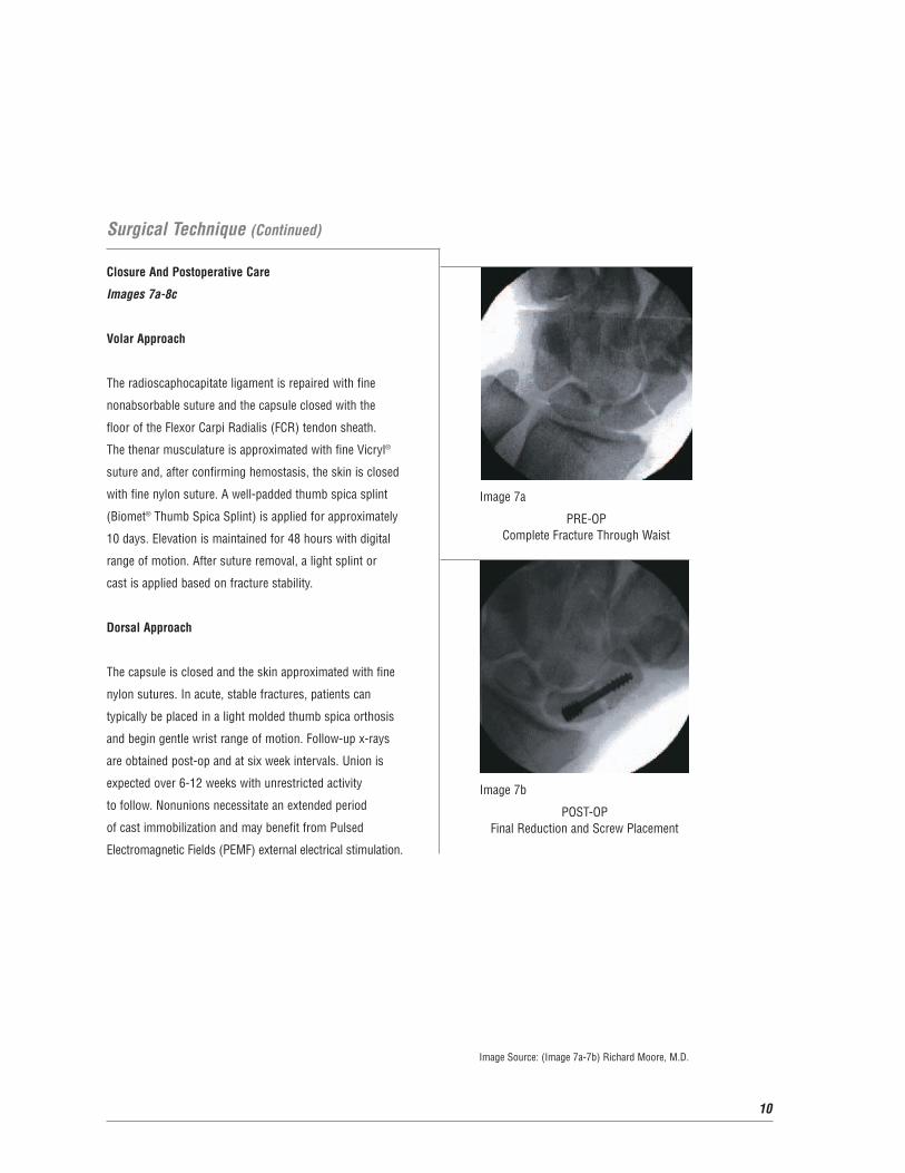
Regardless of the approach, fluoroscopic imaging in
multiple planes is critical to confirm appropriate
intraosseous position of the guide wire to prevent any
articular penetration of the threads. After confirming
position of the guide pin, a second pin should be placed
peripherally to prevent rotation or displacement during
screw insertion.
(Image 4)
Image 2
Initial Pin Stabilization
Image 3
Secondary Anti-rotational Guide Pin
Image 4
Image Source: (Image 2) Richard Moore, M.D.
(Image 3-4) Thomas Graham, M.D.
9
VPC Screw Insertion (For Mini VPC Screw)
Images 5a-6
The color-coded yellow cannulated drill bit (P/N 04850)
is placed on the ratcheting AO handle (P/N 22880) and
under fluoroscopic guidance, manually advanced over the
guide wire to the appropriate depth. The appropriate screw
length can be determined by the calibrations on the drill bit
when advanced through the similarly color-coded drill guide
(P/N 04760), or the cannulated depth gauge (P/N 04655)
can be utilized. The cannulated depth gauge allows
fluoroscopic visualization of the screw tract for precise
measurement. The drill is removed and the cannulated
depth gauge advanced over the guide pin to the appropriate
depth. The shank is seated against the bone and the
appropriate screw length is determined by the calibrated
rule at the proximal end of the handle. The end of the pin
is often visible within the cannulated tract of the depth
gauge but is not utilized for measurement. The depth gauge
is removed and the color-coded yellow counter sink (CSK)
drill bit (P/N 04685) is placed on the ratcheting AO handle
and advanced over the guide wire.
It is important that the CSK drill bit be advanced to the
proximal portion of the threads to allow the screw to be
adequately buried into the subchondral bone and to avoid
protrusion of the head.
A screw approximately 2mm shorter than the drilled depth
is selected to allow proper seating of the screw head and is
placed over the guide wire. The screw should be advanced
across the fracture and the head seated beneath the
articular surface. It is rarely necessary to tap, except in
extremely dense bone; however, the final few turns of the
screw should be performed with the noncannulated solid
screwdriver (P/N 04860) after removal of the guide pin.
It is important to ensure that the screwdriver is completely
engaged in the screw head prior to the final few turns. The
fracture line should be directly visualized to ensure that
there is no rotation or displacement as the screw is inserted
and stability of the graft confirmed in cases of nonunion.
Final fluoroscopic views in multiple planes are obtained to
confirm reduction, intraosseous screw position and
intercarpal relationships.
Image 6
Volar Approach Screw Insertion
Image 5a
Initial Screw Insertion Radiographs
Image 5b
Image Source: (Image 5a-5b) Thomas Graham, M.D.
Image Source: (Image 6) Andre Szymanowicz.
10
Surgical Technique (Continued)
Closure And Postoperative Care
Images 7a-8c
Volar Approach
The radioscaphocapitate ligament is repaired with fine
nonabsorbable suture and the capsule closed with the
floor of the Flexor Carpi Radialis (FCR) tendon sheath.
The thenar musculature is approximated with fine Vicryl®
suture and, after confirming hemostasis, the skin is closed
with fine nylon suture. A well-padded thumb spica splint
(Biomet® Thumb Spica Splint) is applied for approximately
10 days. Elevation is maintained for 48 hours with digital
range of motion. After suture removal, a light splint or
cast is applied based on fracture stability.
Dorsal Approach
The capsule is closed and the skin approximated with fine
nylon sutures. In acute, stable fractures, patients can
typically be placed in a light molded thumb spica orthosis
and begin gentle wrist range of motion. Follow-up x-rays
are obtained post-op and at six week intervals. Union is
expected over 6-12 weeks with unrestricted activity
to follow. Nonunions necessitate an extended period
of cast immobilization and may benefit from Pulsed
Electromagnetic Fields (PEMF) external electrical stimulation.
Image 7a
PRE-OP Complete Fracture Through Waist
Image 7b
POST-OPFinal Reduction and Screw Placement
Image Source: (Image 7a-7b) Richard Moore, M.D.
11
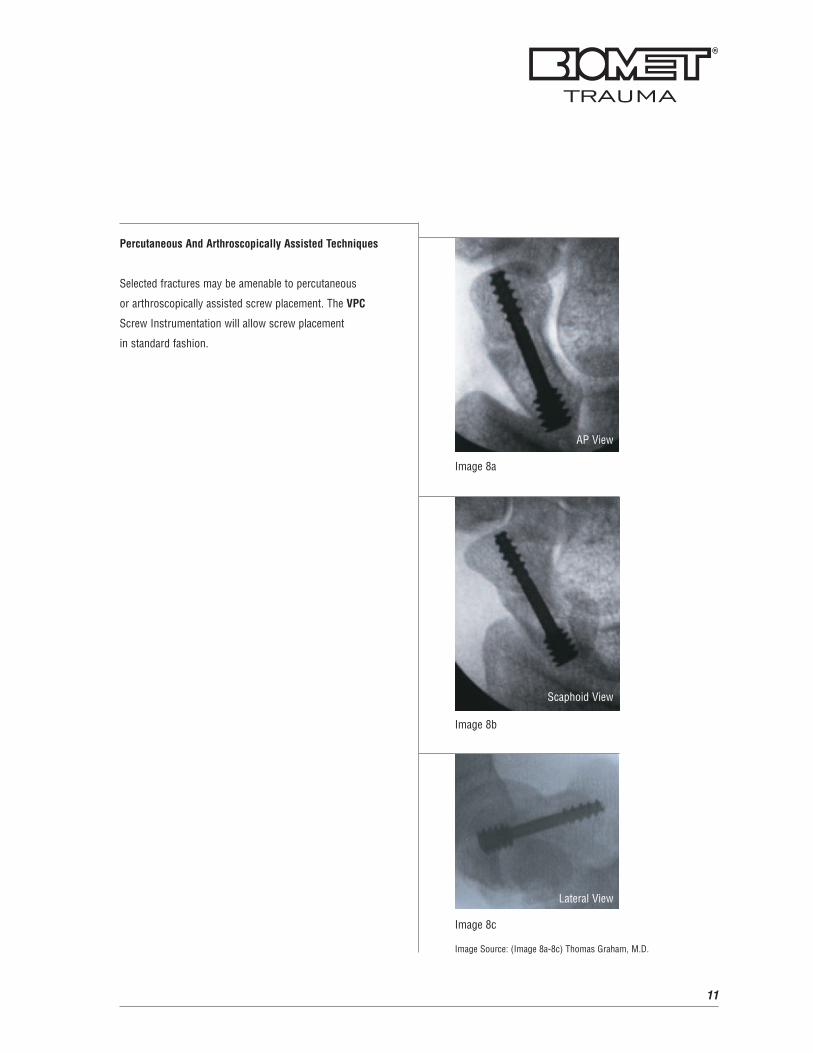
Percutaneous And Arthroscopically Assisted Techniques
Selected fractures may be amenable to percutaneous
or arthroscopically assisted screw placement. The VPC
Screw Instrumentation will allow screw placement
in standard fashion.
Image 8a
AP View
Scaphoid View
Image 8b
Image 8c
Image Source: (Image 8a-8c) Thomas Graham, M.D.
Lateral View

12
Mini VPC Screws And Instruments
Mini VPC ScrewP/N: 04612 through 04630
Mini Countersink (CSK) Drill Bit P/N: 04685
Mini Wire Guide (.039” Dia.)P/N: 04765
Mini Cannulated 1.5mm Hex Driver P/N: 04855
Mini Depth GaugeP/N: 04655
Mini Drill GuideP/N: 04760
Mini 2.0mm Drill BitP/N: 04850
Mini Solid 1.5mm Hex Driver P/N: 04860
13
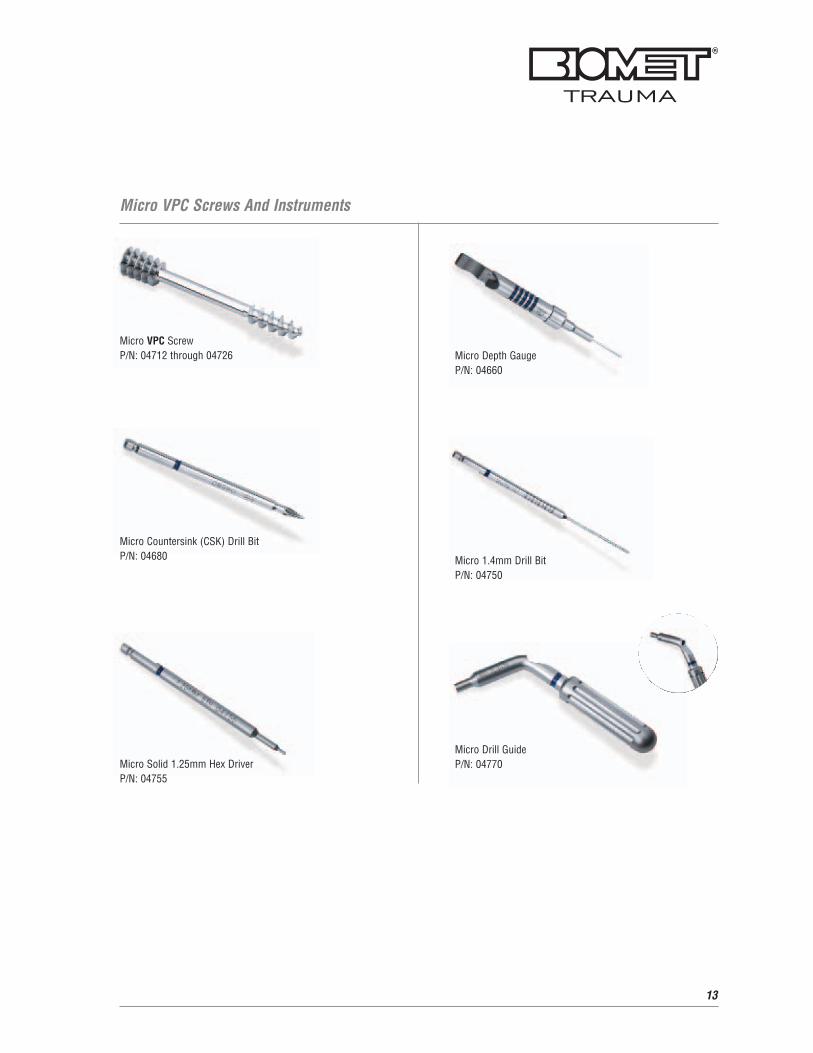
Micro VPC Screws And Instruments
Micro VPC ScrewP/N: 04712 through 04726
Micro Countersink (CSK) Drill Bit P/N: 04680
Micro Solid 1.25mm Hex Driver P/N: 04755
Micro Depth GaugeP/N: 04660
Micro 1.4mm Drill BitP/N: 04750
Micro Drill GuideP/N: 04770
14
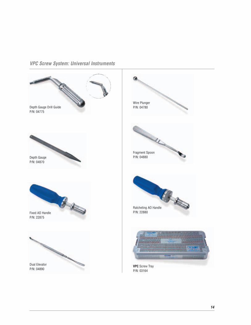
VPC Screw System: Universal Instruments
Depth Gauge Drill GuideP/N: 04775
Depth GaugeP/N: 04870
Fixed AO HandleP/N: 22875
Wire PlungerP/N: 04780
Fragment SpoonP/N: 04880
Ratcheting AO HandleP/N: 22880
VPC Screw TrayP/N: 03164
Dual ElevatorP/N: 04890
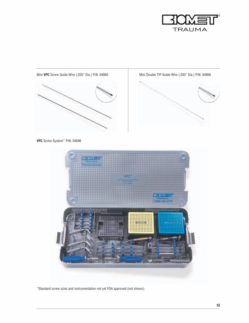
Mini VPC Screw Guide Wire (.035” Dia.) P/N: 04865
VPC Screw System* P/N: 04696
*Standard screw sizes and instrumentation not yet FDA approved (not shown).
Mini Double TIP Guide Wire (.035” Dia.) P/N: 04866
15
16
References
Scaphoid Fracture CMMG 2001.Van Dermark Orthopedic
Specialists.
www.vandemarkortho.com
Freeland, A.E., Bloom, H.T., Moore, J.B., Wegener, E.E.,
ECRL Transfer to the Scaphoid Tubercle for Scapholunate
Instability.
www.hand-surgery.co.uk
Classification of Scaphoid Fractures. Orthoteers.
www.orthoteers.co.uk
A Patient's Guide to Scaphoid Fracture of the Wrist. Hand
University, Associated with Colorado Springs Orthopaedic
Group. © Copyright 2001 Hand University.
www.handuniversity.com
Further Information
This brochure describes the surgical technique used by
Thomas J. Graham, M.D., Richard S. Moore, Jr., M.D. and
Keith B. Raskin, M.D. Biomet Trauma, as the manufacturer
of this device, does not practice medicine and does not
recommend this product or any surgical technique for use
on any individual patient. The surgeon who performs any
implant procedure is responsible for determining the
appropriate product(s) and utilizing the appropriate
technique(s) for said implantation in each individual patient.
For further information, please contact the Customer
Service Department at:
Biomet Trauma
100 Interpace Parkway
Parsippany, NJ 07054
(973) 299-9300 - (800) 526-2579
www.biomettrauma.com
17

18
Notes:

19
Notes:

20
Notes:


Copyright 2006 Biomet, Inc. All rights reserved. P/N 215059L 11/06
For full prescribing information, contact Biomet Trauma, a subsidiary of Biomet, Inc. Unless otherwiseindicated, ™ denotes a trademark, and ® denotes a registered trademark, of one of the followingcompanies: Biomet, Inc.; Electro-Biology, Inc.; EBI, L.P.; Biolectron, Inc.; EBI Medical Inc.; InterporeCross International, Inc.; Cross Medical Products; or Interpore Orthopaedics, Inc.
100 Interpace ParkwayParsippany, NJ 07054www.biomettrauma.com800-526-2579