v.plus series - arnd sauter from "the ground up", the v.plus series has taken full...
TRANSCRIPT

Vertical Machining Center
V.Plus Series
V.Plus-660 V.Plus-800
R.Plus-800 V.Plus-1000

2
MC-750V : 1974
Pioneers of the Vertical Machining CenterMatsuura introduce Our Latest Technology - V.Plus Series
Matsuura Pioneering Machine Tool Excellence Since 1935
Pioneers in the development and manufacture of high quality CNC vertical machining center's, Matsuura have been at the forefront of providing excellence through innovation since 1935. Matsuura's first vertical, the MC-750V was introduced to much global acclaim in 1974 and set the benchmark for precison, quality and productivity. To date Matsuura have supplied in excess of 15,000 vertical machines to every conceivable industry the world over, manufacturing every possible component. Because of our prestigious heritage and established global customer base, we are recognised as a technology leader in todays world of high performance machining. Matsuura customers demand and receive high accuracy, high speed and reliability form our products, with after sales service and applications support that is second to none in the global machine tool supply industry.
Vertical Machining Center V.Plus Series The V.Plus - Matsuura's latest vertical series incorporates all of our hard won knowledge & experience gained from over 30 years of supplying high performance verticals to the worlds leading industries. Designed from "the ground up", the V.Plus Series has taken full advantage of the latest technology & design processes to ensure that it is ready for all applications - no matter how arduos the machining environment, nor how difficult the job. All Matsuura machines are handbuilt by Matsuura Engineers to strict & exacting quality standards - assuring our customers of years of high speed, high accuracy & highly reliable service & operation.
Hand Built to Exacting Quality Standards
34 Years at the Forefront of Vertical CNC Machine Design & Manufacture
15,300 Vertical Machines Supplied to Global Industries Since 1974(Year in 2008)

3
Pioneers of the Vertical Machining CenterMatsuura introduce Our Latest Technology - V.Plus Series
Travel (X/Y/Z) : 660/550/500 mm
: (25.98/21.65/19.68 in.)
Table Size : 940 x 550 mm
: (37.00 x 21.6 in.)
Loading Capacity : 500 kg
: (1,100 lb.)
V.Plus-660
Vertical Machining Center
V.Plus-800
Vertical Machining Center
Travel (X/Y/Z) : 800/550/500 mm
: (31.40/21.65/19.68 in.)
Table Size : 1,150 x 550 mm
: (45.27 x 21.65 in.)
Loading Capacity : 500 kg
: (1,100 lb.)
V.Plus-1000
Vertical Machining Center
Travel (X/Y/Z) : 1,020/550/500 mm
: (40.15/21.65/19.68 in.)
Table Size : 1,150 x 550 mm
: (45.27 x 21.65 in.)Loading
Capacity : 500 kg
: (1,100 lb.)

4
Z-axis Box Slide Way
Highly Rigid Construction, Ultra Precision Assembly
・ Significant ribbing of the bed & column - designed & optimized by FEM analysis.
・ Widely spaced, rectangular section columnguideways on the Z axis are traditionally finishedby hand scraping to minimize wear, offer life longaccuracy & to accommodate the powerfulheadstock/spindle assembly.
・ Grease lubrication is utilized for allaxes ballscrews, & on X & Y linearguides.
FEM-Analysis
Stable, Robust Bed
・ To support longevity, & maintain high accuracyfor the life of the machine, parallelism &straightness of the linear guides is set to within2 μm during manufacture. (Full stroke)
Reliable, High Quality
・ The massive bed, supported at 6 pointsoffers total stability - despite the vastinteria forces generated by all axesduring rapid acc/dec.

5
Chip Flow (Y-axis Front)
Chip Flush (Y-axis rear)
Chip Flow (Y-axis left & right) ・ Chip Bucket・ Coolant Tank (400L)
・ Spindle Taper : BT40 Double Contact
・ Spindle Speed : 12,000 min-1
・ Motor Power : 15/22kW (30HP)
・ Max. Torque : 187 Nm/1,120 min-1
・ Highly accurate telescopic guards areused on all axes, assuring minimumdrag, deflection, vibration & noise, inaddition to protecting the guidewaysfrom the ingress of swarf & chips.
・ Large bedway ducts ensure the unobstructed free flow of swarf into the chipcollection buckets at the rear of the machine.
・ Excellent chip flow - front & rear of Y axistelescopic cover.
・ Deep side troughs.
Highly Rigid Construction, Ultra Precision AssemblyPowerful, Versatile, Unique Matsuura Hi-Tech Spindle
Clean and Efficient Swarf Management
・ Utilizing Matsuura's many decades of pioneering high speed machining experience, our spindles are designed & assembled ′in house′. Matsuura's spindle engineers work in a dedicated clean room complex to assure the highest quality & reliability, the precision spindles are assembled to guarantee a runout of less than 1 μm (0.000039 in.) (actually measured value) at the nose of the spindle.
・ The spindle and the motor are connected by Matsuura's unique coupling. This assembly is designed to prevent the heat from being transferred from the motor to the spindle & contributes to the high rigidity of the spindle.
・ To minimize heat build-up in the spindle, cooled oil is circulated around the outer jacket of the spindle and motor as well as the motor flange, thus sustaining its high accuracy.
・ The standard, double contact of the face & taper, unification of the spindle & drive key features a unique tool clamp
mechanism to improve repeatability and stationary/dynamic rigidity. The clamping force is 14.7kN. This results in excellent material removal rates and surface finish.

6
Powerful, High Performance Matsuura G-Tech Controls
IPC AD-TAP・ Matsuura's unique
spindle motor control technology- AD-TAP, intelligently optimizes the torque V speed characteristics of the spindle motor, depending on the size of the tap used. This provides average reduction of 20% in tapping time.
(Patent Pending)
・ For high speed cutting applications, Matsuura's proven and pioneering software is recommended. When utilizing this software, setting the required part accuracy level is quick, simple and user friendly, allowing you to prioritize precision against speed.
Latest High Performance Control System “Matsuura G-Tech”
( Example number of tapped holes at same time )
8 Tapped Holes
10 Tapped Holes
AD-TAPPrevious Tapping
Machining for General Parts or Mold & Die
Machining for more Complex, Precision Parts
IZ-1/15F
Option
Matsuura G-Tech 30i Matsuura G-Tech 840DI
Advanced Zee LagY
IZ-1/30NF, IZ-2/150NF(Look Ahead Linear Ace./dec.+nano interpolation)
IZ-1/COMP(Max.5,000 Block Look Ahead + Spline Interpolation)
・ Executing the max. 200(IZ-1/30NF)- or 600(IZ-
2/150NF)-block look ahead linear acc./dec. before interpolation achieves a smooth acc./dec. across the mulitiple blocks calculated by nano order.
・ After compressing a maximum of 50 blocks & engaging the 100 Block Look Ahead function, IZ-
1/COMP interpolates & applies to the B-Splineto the nearest point selected.
Solution for High Speed and High Accuracy Machining
Compensating for any Geometric ErrorBetween the Machining Program & Actual Machined Profile
Machining for General Parts or Mold & Die
Machining for more Complex, Precision Parts

7
Latest High Performance Control System “Matsuura G-Tech”Reliable High Performance
Rapid Traverse (X/Y/Z)
50 / 50 / 30 m/minFeedrate (X/Y/Z)
50 / 50 / 30 m/minRapid Traverse Acceleration
0.8 G (Average 0.5 G )
Feedrate Acceleration
0.8 G (Average 0.3 G ) ・ The compact, digital technology feed motors generate extremely high levels of acceleration. This achieves vast reductions of cutting, positioning & non-cutting times.
Previous Model V.Plus-800
Rapid Traverse 30 m/min 50 m/min
Max. Acc. of Rapid Traverse 0.4G 0.8 G
Max. Feedrate 15 m/min 50 m/min
Max. Acc. of Feedrate 0.17G 0.8 G
Comparison of Rapid Traverse/Feedrate with Previous Model
Comparison of Cycle Time
1.6 times
2 times
3.3 times
4.7 times
POCKET MACHINING DEMO
Size : W295 X D195 X H75 mm
Material : Aluminum (A7075)
No. of Tools : 9 tools
* prov ides major sav ing by reducing setup. programing, operat ion and maintenance t imes.Please refer the specia l brochure.
Intelligent Functionality : Simple, Quick, Easy to use
(1,968.5/1,968.5/1,181.1 ipm)
(1,968.5/1,968.5/1,181.1 ipm)
Cycle Time
25%reduced
(1,181.1 ipm)
(590.5 ipm)
(1,968.5 ipm)
(1,968.5 ipm)
(W11.6 x D7.67 x H2.95 in.)
8
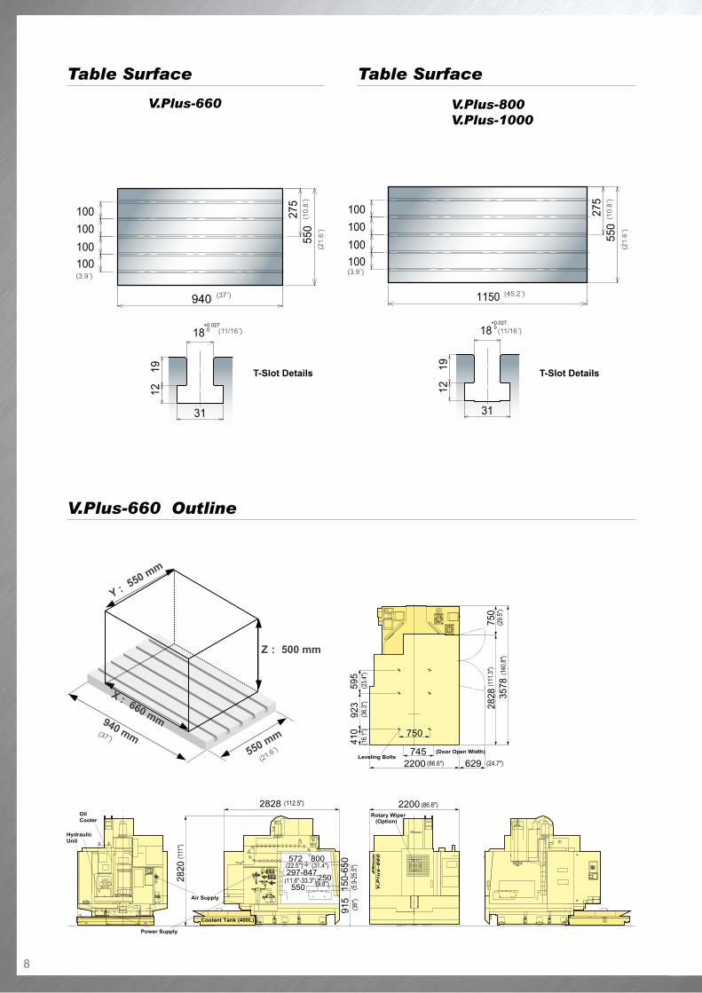
V.Plus-660 Outline
Table SurfaceTable Surface
Z : 500 mm
Y : 550 mm
X : 660 mm
550 mm940 mm
V.Plus-660 V.Plus-800V.Plus-1000
(21.6")
(37")
(3.9")
(37")(1
0.8 "
)
(21.
6 ")
(11/16")
T-Slot Details
(3.9")
(45.2")
(10.
8 ")
(21.
6 ")
(11/16")
T-Slot Details
9
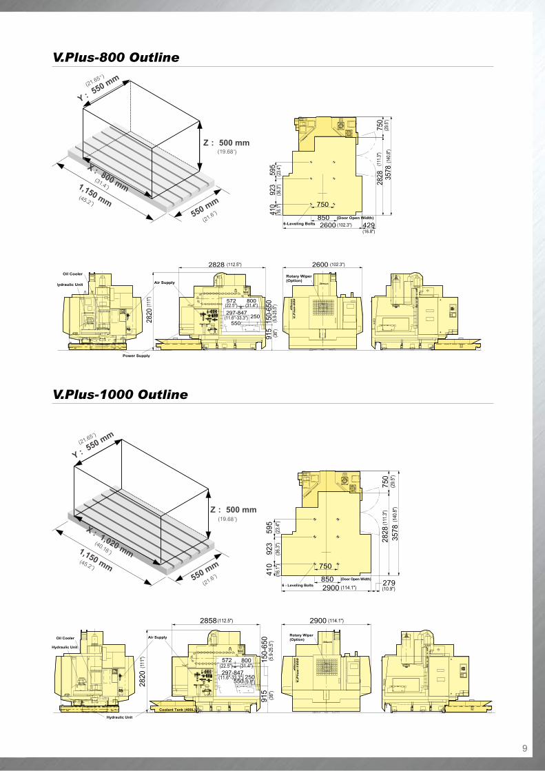
V.Plus-1000 Outline
V.Plus-800 Outline
Z : 500 mm
Y : 550 mm
X : 800 mm
550 mm
1,150 mm
Z : 500 mm
Y : 550 mm
X : 1,020 mm
550 mm
1,150 mm
(21.65")
(40.16")
(19.68")
(45.2")
(21.6")
(21.6")
(21.65")
(31.4")
(19.68")
(45.2")
10
1,150 x 550 mm (45.27 x 21.65 in.)
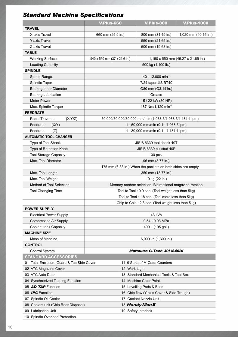
Standard Machine Specifications
TrAvEL X-axis Travel
Y-axis Travel
Z-axis Travel
TABLE Working Surface
Loading Capacity
SPINDLE Speed Range
Spindle Taper
Bearing Inner Diameter
Bearing Lubrication
Motor Power
Max. Spindle Torque
FEEDrATE Rapid Traverse (X/Y/Z)
Feedrate (X/Y)
Feedrate (Z)AuTOMATIC TOOL CHANGEr Type of Tool Shank
Type of Retention Knob
Tool Storage Capacity
Max. Tool Diameter
Max. Tool Length
Max. Tool Weight
Method of Tool Selection
Tool Changing Time
POWEr SuPPLY Electrical Power Supply
Compressed Air Supply
Coolant tank Capacity
MACHINE SIZE Mass of Machine
CONTrOL Control System
V.Plus-660 V.Plus-800 V.Plus-1000
800 mm (31.49 in.)
550 mm (21.65 in.)
500 mm (19.68 in.)
500 kg (1,100 lb.)
40 - 12,000 min-1
7/24 taper JIS BT40
Ø80 mm (Ø3.14 in.)
Grease
15 / 22 kW (30 HP)
187 Nm/1,120 min-1
50,000/50,000/30,000 mm/min (1,968.5/1,968.5/1,181.1 ipm)
1 - 50,000 mm/min (0.1 - 1,968.5 ipm)
1 - 30,000 mm/min (0.1 - 1,181.1 ipm)
JIS B 6339 tool shank 40T
JIS B 6339 pullstud 40P
30 pcs
96 mm (3.77 in.)
175 mm (6.88 in.) When the pockets on both sides are empty
350 mm (13.77 in.)
10 kg (22 lb.)
Memory random selection, Bidirectional magazine rotation
Tool to Tool : 0.9 sec. (Tool weight less than 5kg)
Tool to Tool : 1.8 sec. (Tool more less than 5kg)
Chip to Chip : 2.8 sec. (Tool weight less than 5kg)
43 kVA
0.54 - 0.93 MPa
400 L (105 gal.)
6,000 kg (1,300 lb.)
Matsuura G-Tech 30i /840DI
STANDArD ACCESSOrIES01 Total Enclosure Guard & Top Side Cover
02 ATC Magazine Cover
03 ATC Auto Door
04 Synchronized Tapping Function
05 AD TAP Function
06 IPC Function
07 Spindle Oil Cooler
08 Coolant unit (Chip Rear Disposal)
09 Lubrication Unit
10 Spindle Overload Protection
660 mm (25.9 in.)
940 x 550 mm (37 x 21.6 in.)
1,020 mm (40.15 in.)
11 9 Sorts of M-Code Counters
12 Work Light
13 Standard Mechanical Tools & Tool Box
14 Machine Color Paint
15 Levelling Pads & Bolts
16 Chip flow (Y-axis Cover & Side Trough)
17 Coolant Nozzle Unit
18
19 Safety Interlock

11
The specifications of the Matsuura G-Tech 840DI differ slightly in detail to the Matsuura G-Tech 30i. Please call for details.
Standard NC Specifications Matsuura G-Tech 30i
CONTrOLLED AXES
Controlled Axes 3-axes : X/Y/Z
Simultaneous All-axes Expansion Linear interpolation, Positioning
PrOGrAMMING METHOD
Least Input Increment 0.001mm (0.0001 in.)
Least Command Increment 0.001 mm
Max. Programmable Dimensions ±99999.999 mm (±9999.9999 in.)
Absolute / Incremental Programming G90/91
Decimal Point Input / Computer Type Decimal Point Input
Inch / Metric Selection G20/G21
INTErPOLATION
Positioning G00
Linear Interpolation G01
Circular Interpolation G02/G03 : (CW / CCW)
Helical Interpolation G02/G03 : (CW / CCW)
NANO Interpolation
FEED
Cutting Feed Rate F direct command (mm/min or in./min)
Dwell G04
Handle Feed Manual Pulse Generator : 1 set
0.001/0.01/0.1 mm /1 scale
(0.0001/0.001/0.01 in./1-scale)
Manual Feed Rapid / Jog Feedrate.
Automatic Acc./Dec. Rapid & Cutting Feed : Linear acc./dec.
Rapid Feed Override 0, 1, 25, 50 & 100%
Feed Rate Override 0 - 200%, 10% each
Override Cancel
PArT PrOGrAM STOrAGE & EDIT
Program Memory (512 KB) 1,280 m
Expansion of Number of Programs (1000 pcs.)
Part Program Storage & Editing
Background Edit Function
OPErATION & DISPLAY
Operator's Panel Display : 10.4 in. ( LCD Color ) Full Key
Operation : Full Key, 10+2 Software Key
Run Hour/Parts Number Display
Back Ground Graphic Function
I / O FuNCTION & DEvICES
Reader Punch Interface (1,2 ch.) RS-232C
Internalized Ethernet 100/10 BASE-T
DNC Operation, Data Input/Output Memory Card, Compact Flash Card
STM Function
Spindle Function (S Function) S 5 Digits Command
Spindle Speed Override 50 - 120% (Increment 10%)
Tool Function T4 Digits Command
Miscellaneous Function M3 Digits Command
TOOL OFFSET
Tool Offset Memory C Offset for figure & Wear (D/H Code)
Tool Offset Number Addition Total 99
COOrDINATE SYSTEM
Manual Reference Point Return
Reference Point Return Check G27
Coordinate System Setting G92
Automatic Coordinate System Setting
2nd Reference Point Return G30
Work Coordinate System Setting G54-G59
OPErATION SuPPOrT FuNCTION
Label Skip
Single Block
Optional Stop
Optional Block Skip
Dry Run
Machine Lock
Mirror Image
Z-Axis Command Neglect
Feed Hold
Cycle Start
Data Protection Key
Help Function
PrOGrAMMING SuPPOrT FuNCTION
Circular Interpolation by Radius R
Canned Cycle G73, G74, G80-G87, G89
Sub Program Calling (Quadruple)
Exact Stop Check G09, G61
Exact Stop Mode G61, G64
Programmable Data Input G10
Automatic Corner Deceleration
Custom Macro
Dynamic Graphic Display
Rigid Tap
IZ-1/15F
AuTOMATIC SuPPOrT FuNCTION
Skip Function G31
SAFETY / MAINTENANCE
Emergency Stop
Over Travel
Stored Stroke Check1
Self Diagnosis Function
Stroke Limit Check Before Move
12
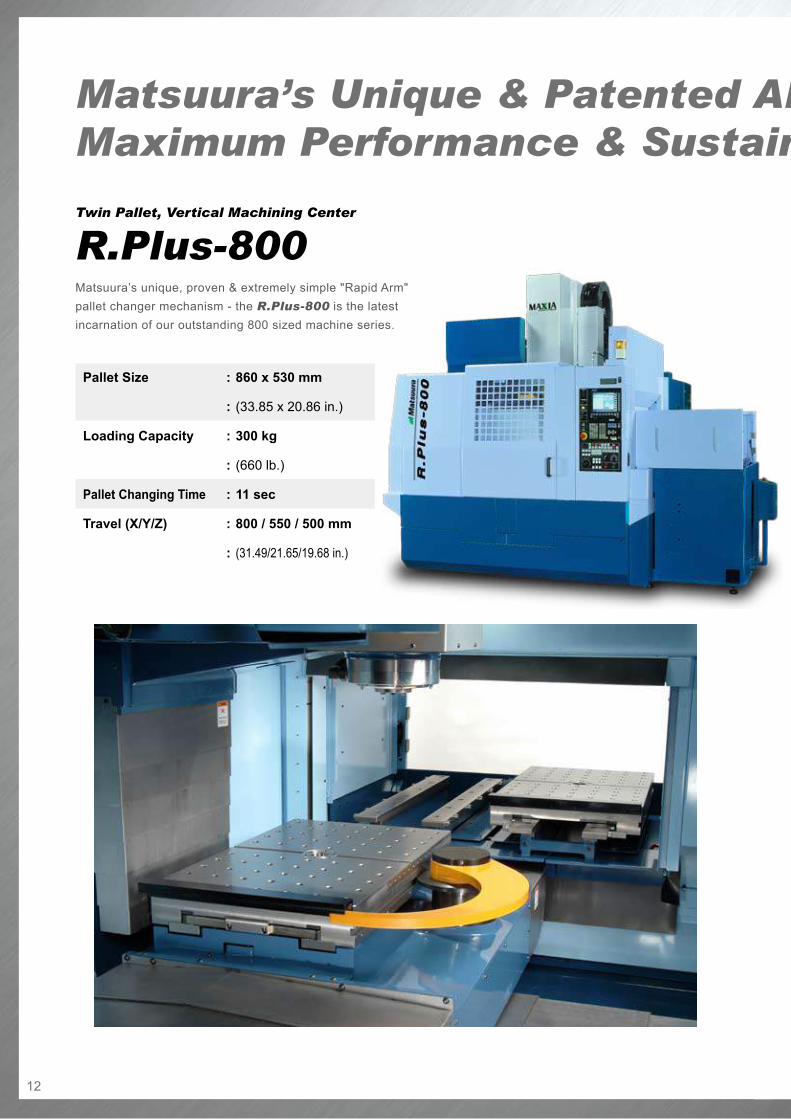
Twin Pallet, Vertical Machining Center
R.Plus-800Matsuura’s unique, proven & extremely simple "Rapid Arm" pallet changer mechanism - the R.Plus-800 is the latest incarnation of our outstanding 800 sized machine series.
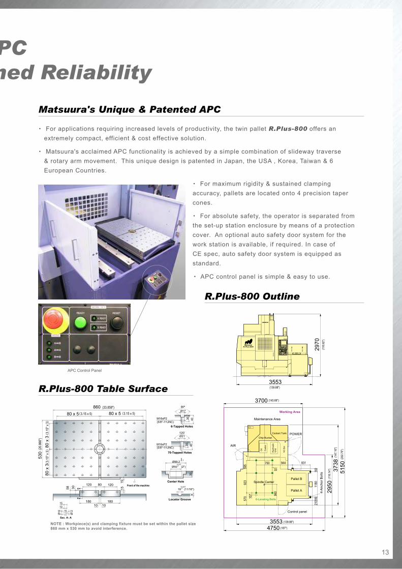
Matsuura’s Unique & Patented APCMaximum Performance & Sustained Reliability
Pallet Size : 860 x 530 mm
: (33.85 x 20.86 in.)
Loading Capacity : 300 kg
: (660 lb.)
Pallet Changing Time : 11 sec
Travel (X/Y/Z) : 800 / 550 / 500 mm
: (31.49/21.65/19.68 in.)
13
R.Plus-800 Outline
R.Plus-800 Table Surface
Matsuura’s Unique & Patented APCMaximum Performance & Sustained Reliability
・ For applications requiring increased levels of productivity, the twin pallet R.Plus-800 offers an extremely compact, efficient & cost effective solution.
・ Matsuura's acclaimed APC functionality is achieved by a simple combination of slideway traverse & rotary arm movement. This unique design is patented in Japan, the USA , Korea, Taiwan & 6 European Countries.
・ For maximum rigidity & sustained clamping accuracy, pallets are located onto 4 precision taper cones.
・ For absolute safety, the operator is separated from the set-up station enclosure by means of a protection cover. An optional auto safety door system for the work station is available, if required. In case of CE spec, auto safety door system is equipped as standard.
・ APC control panel is simple & easy to use.
Matsuura's Unique & Patented APC
APC Control Panel

14
80 tool Magazine
0il & Air LubricationG-Tech 840DI
Options (1)
20,000 min-1 Spindle Motor Power & Torque Diagram
G-Tech 840DIG-Tech 30i
G-Tech 30i
20,000 min-1
30,000 min-1
30,000 min-1Spindle Speed (min-1)
30,000 min-1 Spindle Motor Power & Torque Diagram
Spindle Speed (min-1)
30,000 min-1 Spindle Motor Power & Torque Diagram
Spindle Speed (min-1)
Spindles・ 20,000 min-1
・ 30,000 min-1
Number of Tools・ 40 tools
・ 80 tools
Rotary Wiper
8 Sets of Extra M Function
Auto Grease Supply Unit (X/Y)
Weekly Timer
Operation / Maintenance
High Accuracy Control
Safety Features
・ Scale Feedback System (X/Y, Z, X/Y/Z)
・ Thermal Displacement Compensation Function
・ Coolant Flow Checker
・ 8 Sets of Extra M Function
・ Weekly Timer
・ 3 Color Status Light (red, green, yellow)
・ Spindle run Hour Meter
・ Automatic Operation run Hour Display unit
・ Movable Manual Pulse Generator
・ Mist Separator unit
・ rotary Wiper (Air Supply System)
・ Coolant Flow Checker
・ Auto Grease Supply unit (X/Y)
・ Door Interlock for Total Splash Guard
Scale Feedback System
15
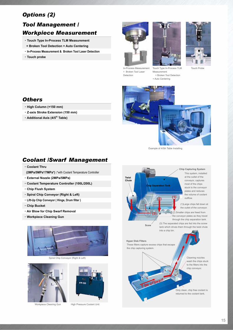
Options (2)
This system, installed at the outlet of the conveyor, captures most of the chips stuck to the conveyor plates and reduces the volume of coolant outflow.
(1)Large chips fall down at the outlet of the conveyor.
(2) Smaller chips are freed from the conveyor plates as they travel through the chip separation tank.
(3) The separated chips are fed into the screw tank which drives them through the twist chute into a chip bin.
Workpiece Cleaning Gun High Pressure Coolant Unit
Spiral Chip Conveyor (Right & Left)
(2)
(3)
Scew
Chip Separation Tank
Chip Capturing System
Twist Chute
(1)
Flow of Swarf
Cleaning nozzles wash the chips stuck to the filters into the chip conveyor.
Only clean, chip free coolant is returned to the coolant tank.
These filters capture excess chips that escape the chip capturing system.
Hyper Disk Filters
Coolant /Swarf Management・ Coolant Thru
(2MPa/5MPa*/7MPa*) :*with Coolant Temperature Controller
・ External Nozzle (2MPa/5MPa)
・ Coolant Temperature Controller (100L/200L)
・ Chip Flush System
・ Spiral Chip Conveyor (right & Left)
・ Lift-Up Chip Conveyor ( Hinge, Drum filter )
・ Chip Bucket
・ Air Blow for Chip Swarf removal
・ Workpiece Cleaning Gun
Touch ProbeTouch Type In-Process TLM Measurement + Broken Tool Detection + Auto Centering
In-Process Measurement + Broken Tool Laser Detection
Example of 4/5th Table Installing
Tool Management /
Workpiece Measurement
Others
・ Touch Type In-Process TLM Measurement
+ Broken Tool Detection + Auto Centering
・ In-Process Measurement & Broken Tool Laser Detection
・ Touch probe
・ High Column (+150 mm)
・ Z-axis Stroke Extension (150 mm)
・ Additional Axis (4/5th Table)
Printed on recycled paper.
● Product specifications and dimensions are subject to change without prior notice.
● The photos may show optional accessories.
URL : http://www.matsuura.co.jp/E-MAIL : [email protected]
Matsuura Machinery corporation1-1 Urushihara-cho Fukui City 910-8530, JapanTEL : +81-776-56-8106 FAX : +81-776-56-8151
Matsuura europe GmbhOtto-Von-Guericke-Ring 10a 65205 Wiesbaden-Nordenstadt, GermanyTEL : +49-6122-7803-80 FAX : +49-6122-7803-33E-MAIL : [email protected] : http://www.matsuura.de/
Matsuura Machinery pLcBeaumont Center Whitwick Business Park, Coalville Leicestershire LE67 4NH, EnglandTEL : +44-1530-511-400 FAX : +44-1530-511-440E-MAIL : [email protected] : www.matsuura.co.uk
Matsuura Machinery GmbhOtto-Von-Guericke-Ring 10a 65205 Wiesbaden-Nordenstadt, GermanyTEL : +49-6122-7803-0 FAX : +49-6122-7803-33E-MAIL : [email protected] URL : http://www.matsuura.de/
eLLiott Matsuura canaDa inc.2120 Buckingham Road Oakville Ontario L6H 5X2, CanadaTEL : +1-905-829-2211 FAX : +1-905-829-5600E-MAIL : [email protected] : http://www.elliottmachinery.com/
MMts corporation65 Union Avenue Suite2, Sudbury Massachusetts 01776, U.S.A.TEL : +1-978-443-5388 FAX : +1-978-443-9524
Products are subject to all applicable export control laws and regulations.
EF/3/4/EG-E2.0t 200802 500S