walter reed army institute of researchdtic.mil/dtic/tr/fulltext/u2/a233058.pdf · walter reed army...
TRANSCRIPT
WALTER REED ARMY INSTITUTE OF RESEARCH
"1EDICAL EVALUATION OF NONFRAGMENT INJURY EFFECTS
IN ARMORED VEHICLE LIVE FIRE TESTS
Instrumentation Requirements and Injury Criteria
DEPARTMENT OF RESPIRATORY RESEARCH DIVISION '·Of MEDICINE
WASHINGTON, D.C. 20307-5100
• ffiuRiTY CLASSI~ICATION OF THIS PAGT - = - Form Approved
REPORT DOCUMENTATION PAGE OMB No 0704-01&8 fxp. Date Jun 30, 7 986
1a REPORT SECURITY CLASSIFICl\ TION 1b -RES fRICTIVE MARKINGS
Tlncli'l"'"'ified 2a SECURITY CLASSIFICATION AUTHORITY 3 DISTRIBUTION I AVAILABILITY OF REPORT
2b DEC!.ASSIFICATION I DOWNGRADING SCHEDULE Lmclass if ied /w1 Jimi ted
4. PERFORMING ORGANIZATION PI:PORT NUMBER(S) 5 MONITORING ORGANIZATION llEPORT NUMBER($)
6.1. N.'::t.ME OF PER'F'OR'Mi'N(.; ORGANIZATION (,b OFFICE SYMBOL 7a NAME OF MONITORING ORGANIZATION
Walter Reed Army Institute (If applicable)
of Research &-:;RD-UWH-E 6c ADDRESS (City, State, and ZIP Code) 7b. ADDRESS (City, St,,te, and ZIP Code)
Division of I'-Wicine Walter Reed Army Institute of Research ~'Jm;hincrton D.C 20307-_S}.Q.Q
Sa. NAME: OF FUNDING /SPONSORING 8b. OFFICE SYMBOL 9 PROCUREMENT INSTRUMENT IDENTIFICATION NUMBER ORGANIZATION (If aiJplicable)
-8c. ADDRESS (City, State, dnd ZIP Code) 10 SOURCE OF FUNDiN.S NUMBERS
PROGRAM PROJECT TASK WORK UNIT ELE'MENT NO NO NO ACCESSION NO
62777A BE1627T/A87 AB 042
11 Tl fLE (Include Security CI.Jssification) M3dical Evaluation of Nonfragrrent In:jury Effects in A.rmonx.l Vehicle Live Fire Tests. Inst:n.T:"entu.t ion Requ.ixcrrcnts and Injury Criteria.
12. PERSONO.L AUTHOR($)
Ripple, Gary R., Mundie, 'l'hanas G. 13a. TYPE OF REPORT r 3b TIME COVERED r4 DATE OF REPORT ( Ye<Jr, Month, O.Jy) r 5 P.AGt COUNT
FROM _ TO 1989 Scpt:crnber lR '16 SUPPLEMENTARY NOTAT!ON
Prepared in coopcru.tion with individuals fran tl11.::o u.s. A.nny krcm:xhca1 !~esc arch Loboratory the u.s. Arnr; BuJ 1 i ::;tic He search Laboratory and Cc:mbJt Svstemc 'l'est k~t ivitv
17 COSA 1 I CODES 18. SUBJECT TERMS (Contmue on reversed necess..ory <Jnd identify by bluck number) ~·
behind U....."ITtor effects, blast t:ox.ic burns FIELD GPOUI' SUB-GROUP ovcrpressw::-e , gu.ses, 1---· --r--acceleration, l . fjre te~;ting, AFES, ~>hoc~, .incu.pacitation f-· ~-lVC
ccmbat <:<1!3lhlltv care c..'~erc iSl' 19. ABSTKACT (Continue on reverse d necessary and identify by block nunrber)
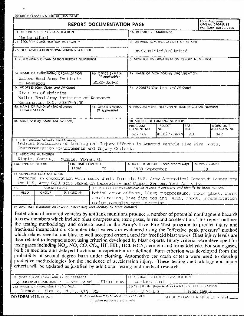
Penetration of armored vehicles by antitank munitions produce a number of potential nonfragment hazards to crew members which include blast oveQressure, toxic gases, burns and ac<:eleration. This report outlines the test!ng methodology and criteria used in the Army's Live Fire Test program to predict injury and fractional incapacitation. Complex bla"t waves are evaluated using the "effective peak pressure" method which relates reverbu·ant bla..~t to well accepted criteria used for freefield blast waves. Blast inj11ry levels are then related to incapacitation using ~riterion developed by blast experts. In.iury criteria were developed for toxic gases including N02, NO, CO, C02, HF, HBr, HCL HCN, acrolein anJ formaldehyde. For some gases, both immediate and delayed fractional incapcitatinn are defined. Burn cri~erion was developed from the probability of second degree burn under clothing. Automotive car <:ra-;h criteria were used to develop predictive methodologies for the incidence of acceien<.tion injury. 111ese testing methodology and injury criteria will he updated as justified by additional testing and rm~dical research.
.'0 [)ISTR1l1Uf10N 1 AVAILMllLITY Of Afl)'Tf,ACT 21 M3)Tf-iM_f Sf(URiiY CL/•SSiti(ATI(HJ
XJ 'J•\IU ASSif IE D/UNLIMI Tf {) [-] 5AIV1[ A) RPT [1 OTIC USll~'> lJrJr'iu~;~;Ji l<Xl 21d NAME OF- Rf)PONSIBI E :r>JOIVIDUAL
'i'lHTID~i c. Muno.1c- l'll.U.
DO FORM 1473,84 MAR
C: I'~ 1'-1S
22b lll.tPHONF (ln(/•Jde Are.-1 Code)J 22c Of FlU )Y:v180L
lCII ---•1 J -,_ <, ~ HO ~ :m l -I rvJJ L-_E.
83 APR Pd1t1un mdy be uwd unto! exhdu~ted
All otlwr ed•t•on~ .Hi.' obl<>l•'t"

•
f\IEDICAL EVALUATION OF NONFRAGMENT INJURY EFFECTS
IN ARMORED VEHICLE LIVE FIRE TESTS
Instrumentation Requirements and Injury Criteria
Editors
MAJ Gary R . Ripple, M.D. (1) CPT Thomas G. Mundie, Ph.D. (1)
Contributors
LTC Yancy Y. Phillips, M.D. (1) LTC Kenneth G . Torrington, M.D. (1) MAJ Gary R. Ripple, M.D. (1) CPT Thomas G. Mundie, Ph.D. (1) Dr. Kenneth T. Dodd, Ph.D (1) Dr. Nahib AJem, Ph.D (2) Mr. Joseph L. Haley (2) Mr. David Neades (3) Dr. James Faller, Ph.D (4) Mr. Craig Herud ( 4) Mr. Scott Walton (4)
(1)
(2)
(3)
(4)
Walter Reed Army Institute of Research Washington, DC 20307-5100
US Army Aeromedical Research Laboratory Ft. Rucker, AL 36362-5292
US Army Ballistic Research Laboratory Aberdeen Proving Grounds, MD 21005-5066
Combat Systems Testing Activity Aberdeen Proving Grounds, MD 21005-5066
.t
TABLE OF CONTENTS
INl"RODUCflON............................................................................................ 3
Background............................................................................................ 3
Purpose and Objectives....................................................................... 4
INSTRUMENTATION REQUIREMENTS.............................................. 5
Blast Overpressure............................................................................... 5
Thermal Radiation............................................................................... 6
Toxic Gases............................................................................................ 7
Acceleration........................................................................................... 11
INJURY ASSESSMENT CRITERIA.......................................................... 12
Blast Overpressure............................................................................... 12
Thermal Radiation............................................................................... 14
Toxic Gases............................................................................................ 17
Acceleration............................... ............................................................ 22
Flash Effects.......................................................................................... 24
Combined Injury................................................................................... 24
BIBLIOGRAPHY............................................................................................. 26
Armed Forces Epidemiology Board Endorsement.................................... 35
DISTRIBUTION LIST...................................................................................... 37
1.
2.
FIGURES
Typical Blast Wave Behind Defeated Armor ............................... .
"Effective Peak Pressure" Evaluation of Blast Wave ................. ..
33
34
INTRODUCDON
BACKGROUND
The survivability of armored combat vehicles (ACV) depends, in part, on the vulnerability of both the vehicle and the crew. Until recently, evaluation of the vehicle vulnerability was limited to an evaluation of an armor's ability to prevent penetration by a specified anti-armor threat and evaluation of vehicle systems and components through selective engineering tests. However, questions arose regarding the accuracy of assessing weapon platforms through selective component testing and then extrapolating by computer modeling to determine ACV vulnerability /survivability in combat. This prompted the Office of the Secretary of Defense to initiate the Joint Live Fire Program in 1984 (1 ). Congress then passed Live Fire Test legislation in 1987 to require live fire testing of all United States weapon platforms against realistic combat threats (Amendment Title 10, U.S.C. 139). This law stipulated a weapon platform may not proceed beyond low-rate initial production until "realistic survivability testing is complete." The purpose of such testing is fourfold:
a. To assess the vulnerability of U.S. weapon systems (vehicle and crew) to realistic combat threats.
b. To assess the lethality of U.S. conventional combat systems against foreign weapons systems.
c. To produce design changes which would increase crew and/ or vehicle survivability on the battlefield.
d. To produce a database which would be used to improve computer modeling of weapons system vulnerability.
Behind armor events produce a number of potential hazards to the crew (2,3). Penetration of armor by a high explosive antitank (HEAT) munition or a kinetic energy (KE) round creates a spall cone, a spray of hot fragments emanating from the munition and the defeated armor, which might result in fragment injuries to crew. Within this spall cone a thermal pulse occurs which can ignite essentially any flammable material. In addition to these principle effects, a blast overpressure is generated in the crew space, a brief intense flash occurs, accelerative loads are delivered to the crew through the vehicle structure and toxic gases might be generated by heat from burning materials or from the penetrator. Previously, these ancillary effects were not figured into survivability because they were considered inconsequential compared to the considerable threat of burns and fragment wounds. However, progress in armored system design has resulted in significant limitations of the direct damage done by threat penetiation. Fragment damage has been reduced by the decreased penetrability of the armor, the wearing of personal body armor and the use of spall suppression linings. The threat of crew space fires has been markedly reduced by the proper stowage and compartmentalization of ammunition and other flammables and by the use of an automatic fire extinguishing system (AFES). These improvements, the
3
.. - ~.
operational ruggedness of the ACV and the life threatening nature of the battlefield outside of the vehicle make it likely a soldier will survive a penetration, stay in the ACV and continue his combat mission. This increases the importance of accurately evaluating the ancillary effects described above as possible causes of crew injury or incapacitation. It also raises the question of possible health risks created within an ACV should the crew remain in the vehicle after armor penetration. For these reasons, the Army Medical Department (AMEDD) was tasked to evaluate nonfragment injuries for live fire testing. This required AMEDD researchers and weapons testers to identify potential hazards and standardize instrumentation to collect data representative of injurious circumstances. Criteria have been established capable of predicting injury to brief, high intensity blast overpressure thermal exposure, accelerative loads and toxic gases. Medical literature revealed little data which could be directly applied to these environments. Evaluating hazards from thermal exposure and accelerative loads required an application of existing data for the peculiarities of the environment behind defeated annor. Evaluating hazards from blast overpressure and toxic gas exposure required investigation through medical research specifically designed to characterize the hazards in these environments. Predicting injuries and fractional incapacitation in these environments is not an exact science and will require refinement as addition data is presented.
PURPOSE AND OBJECTIVES
From a medical effects standpoint, the purpose of live fire testing is to characterize the environment behind defeated armor and then to predict the effect of this environment on the ability of the crew to perform its mission and/ or the effect of this environment on injury to the crew. This technical report describes the methodology developed to date for the acquisition of data during live fire testing as well as for the prediction of injuries resulting from these events, and the interpretation of those injuries in terms of their effect on crew performance. Information provided within this report has been used in the Bradley live fire test (LIT) and the Abrams LIT (4,5).
Three basic medical questions are addressed in assessing the health hazards identified by live fire testing.
a. Is the crew injured and/or incapacitated by fragments and/or fire immediately generated by the armor penetration?
b. If the answer to "a." is "No", is the crew immediately injured or incapacitated by the blast, acceleration, toxic fumes, or flash effects?
c. If a crew member is not immediately injured or incapacitated as in "a." or "b." above, is he at risk of delayed injury from the initial insult or further injury by remaining in the vehicle and continuing his combat mission?
4

INSTRUMENTATION REQUIREMENTS
This section establishes the appropriate measurement methodology for live fire testing of armored combat vehicles. Instrumentation requirements are described for blast overpressure, thermal/optical radiation, toxic gas concentrations and acceleration levels at crew positions throughout the test vehicle. These measurements enable a full characterization of the crew space environment. Data should be collected at all appropriate crew positions as regional differences within the vehicle play a large role in determining the hazard for each crew member. Instrumentation requirements should be tailored to each particular firing depending on the shot line and information required. A shot by shot instrumentation plan should be established before testing begins.
Physical measurements necessary to characterize the crew space habitability after an armor penetration include:
1. Blast Overpressure Levels 2. Thermal Radiation Levels 3. Toxic Gas Concentrations 4. Crew Accelerative Loads
BlAST OVERPRESSURE INSTRUMENTATION
Capturing representative and reproducible blast overpressure measurements inside the reverberant space of an ACV is difficult. The injurious effects associated with the complex interactions between the primary blast, the rebounding pressure waves and the human body can not be directly assessed by available freefield blast injury criteria. Eventually injury criteria for complex waves will be available. Therefore, accurate measurement of these complex pressure events is necessary to better characterize the event and to provide insight to guide blast research.
The measurement guidelines presented in this section follow the recommendations set forth by a panel of blast experts in 1983 (6). The blast environment experienced by the crew inside an ACV should be measured using piezoresistive pressure transducers (Endevco Model 8530B-50 or equivalent). The transducers should be positioned ·as close as possible to the anthropomorphic crew simulators. In addition, one or more pressure transducers can be mounted flush in the center of the roof and/or walls. A summary of the shot by shot instrumentation plan should be established and written in the detailed test plan. The characteristics of the Endevco pressure transducer are listed below:
Type: Piezoresistive Circuit: four-arm bridge Linear Range (kPa): 0-850 Nominal Output (mV): 750 Output Impedance (ohms): 1600 Resonance (kHz): 240 Acceleration Sensitivity (Pa/g): 1.4
5
.. \ - -
Diaphragm Diameter (mm): 3.8
Data should be recorded on a digital system with analog magnetic tape backup to reduce risk of data loss. Signal conditioning should be provided by a Pacific Instruments Model 8255 Transducer Amplifier, Precision Filters 316 Programmable Signal Conditioner, or equivalent to eliminate spurious signals and to provide equivalent electrical performance for the data acquisition system being used. Overall system accuracy should be ±7%. Prior to each shot, the pressure transducers should be lab calibrated and the data acquisition system field checked by use of voltage insertion tests. Amplifier gain settings should be based on expected pressure levels for each shot with a maximum range of 600 kPa.
The collected data should be presented as time history plots of pressure (kPa) versus Time and Impulse (kPa-rnsec) versus Time. Pre-trigger memory should provide 25 rnsec of pressure data prior to the blast event. Time of occurrence of possible hatch doors opening should be recorded on tests where vehicle hatches are closed prior to the shot. Gauge identification, location, sensitivity, system gain, and filtering information should be provided on each time plot. Blast data should be evaluated for accuracy before its release to medical evaluators.
THERMAL RADIATION INSTRUMENTATION
Accurate prediction of crew survivability in a fire within an ACV is difficult because of the unpredictable thermal environment and the variability of the body's response, especially when protected by clothing (31-32). A fire suppressed in less than 250 rnsec is very unlikely to burn a soldier beneath his uniform (31-32). AFES are engineered to extinguish fires in 250 rnsec. The first 10 seconds after an ACV penetration is considered the most critical period for burn injury. Intense thermal events lasting longer than 10 sec would either be catastrophic or would necessitate the crew evacuating the vehicle. Thermal measurements should be recorded continuously for the first 30 sec and thereafter every 5 sec for a minimum of 5 min.
The thermal environment behind armor should be evaluated with both free air temperature thermocouples and with heat flux calorimetry. Thermocouple data are necessary for assessing injury and for monitoring the presence of fires within the test vehicle. Calorimetry data probably allow more precise prediction of skin burns since they indicate actual heat transfer. This is particularly important where measurements are taken under clothing, at skin level. Transducer characteristics are listed below.
Transducer Type
Model Operating Range Response Time
Radiation Convection
Thermocouple
TypeK -200 to + 1250°C
70 ms
6
Calorimeter
Asymptotic 0 to 25 BTU /ft2 /sec
30 rns 65 to 443 ms
Because almost any type of clothing will substantially limit skin bums, sensors should be placed at standard positions on the crew simulator surface and on the crew simulator clothing at the chest, waist and calf. Exposed sensors should be placed in the facial region if bead coverings are routinely worn. Both thermocouples and calorimeters should be used in all sensor locations.
The data acquisition system should be capable of continuously recording thermocouple and calorimetry data for at least 30 seconds with accuracy of.± 0.05%. It should also be capable of monitoring the vehicle at 5 sec intervals thereafter to identify late fires within the vehicle. Temperature and heat transfer information should be presented in tabular form as the cumulative integral of the energy measured for each second during the first 10 seconds, and for every 15 seconds thereafter. Temperature-time histories should be provjded in graphics as well as tabular form to allow correlation of peak temperatures with specific test events.
TOXIC GAS INSTRUMENTATION REQUIREMENTS
During overmatching attack, toxic gas measurements should be made at appropriate crew positions within the test vehicle but outside of the spall cone. As a minimum, one full set of measurements should be collected from each compartment within the vehicle (ie: driver's compartment and turret on tanks). The location and type of each sampler should be specified in the detailed test plan. Toxic gas measurements are normally not necessary for non-penetrating attacks, unless ingestion of smoke and fumes by the vehicle ventilation system or shock induced ruptures of chemical containers (i.e. batteries, hydraulic reservoirs, etc) are likely.
Toxic gas measurements of the air filtered through individual protective masks or a collective protection system (where available) should also be made. Carbon monoxide and oxides of nitrogen will penetrate these filters to varying degrees, exposing the crew to these toxic gases even after they have donned their masks. Systems with improperly located external intakes might ingest hazardous levels of gases from outside of the vehicle and supply it to the crew. Systems with internal intakes will recirculate contaminated interior air. Measurements of pyrolysis products are not necessary, since test data indicate that hydrogen flouride (HF), hydrogen bromide (HBr) and hydrogen cyanide (HCN) in the doses expected will not penetrate the filters ( 44 ). Whenever possible, measurements should be made with continuous spectrometric analyzers to obtain complete concentration-time histories. For chemical species for which suitable continuous analyzers do not exist, discrete samples should be collected for off-line laboratory analysis. Single samples covering the entire test period or multiple "time slice" samples should be collected to permit construction of a concentration vs time history. The concentrations obtained from these "time slices" represent average concentrations over the time period sampled, thus peak concentrations cannot be obtained by this method.
7
e Particle Size Measurements:
Measurements of the weight and size distribution of respirable solid particles (0.5 to 10 microns aerodynamic particle size) should also be made, using cyclones or cascade impactors, depending on the gradation of the measurements desired. Both methods are gravimetric. The total quantity of respirable material should be determined using a cyclone or a cascade impactor. Cyclones remove the larger particles and collect the respirable fraction on a fine pore filter. Cascade impactors separate the particles by aerodynamic particle size and collect the fractions on 4 to 8 separate stages. Air flow rates through cyclones or cascade impactors must be maintained at the manufacturer's recommended flow rate to insure proper particle sizing.
Sample Flow Rate Measurements:
When discrete samples are collected, accurate measurements of the volume of air sampled are also required, to permit calculation of concentrations of the species in air. The laboratory analysis will only determine the weight of material collected. Continuous mass flow measurements are preferred, since they are capable of detecting changes in flow rates during the sampling period caused by clogging of the collector or damage to the sample line. If multiple samplers are connected to a vacuum manifold, each vacuum line should be equipped with a critical orifice to prevent unbalancing the flow rates of all samplers in the event of clogging or cutting of a sample line.
Continuous Gas Measurements:
Concentrations of carbon monoxide (CO), carbon dioxide (C02) , nitrogen monoxide (NO), nitrogen dioxide (N02) should be measured continuously at each location specified in the test plan. For systems equipped with AFES, continuous measurements of the fire extinguishing agent concentration (usually Halon 1301, or possibly Halon 1211 or 2402) should also be made at each location. Due to the transient nature of the gas concentrations produced during these types of tests, the analyzers used should have fast response times, preferably less than 10 sec from baseline to 90% of full scale. CO, C02 and Halon measurements should be made using nondispersive infrared gas analyzers, such as Leybold-Heraeus BINOS or equivalent. N02 measurements should be made using nondispersive ultraviolet gas analyzers, such as BINOS or chemiluminescent gas analyzers, such as Thermoelectron Model 40, or their equivalents. Nitrogen monoxide (NO) measurements should be made using chemiluminescent gas analyzers, such as the Model 40; measurements should not be made using nondispersive infrared instruments due to interferences from co, col and water vapor. Any instruments used must be equipped with the proper filters to minimize cross-interferences and should be checked prior to use. The recommended analyzer characteristics are as follows:
8
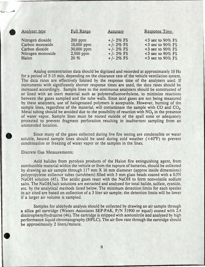
e Analyzer type Fu11 Ran2e Accuracy Response Time
Nitrogen dioxide 200 ppm +/- 2% FS <3 sec to 90% FS Carbon monoxide 10,000 ppm +/- 2% FS <3 sec to 90% FS Carbon dioxide 30,000 ppm +/· 2% FS <3 sec to 90% FS Nitrogen monoxide 2,500 ppm + /· 2% FS <3 sec to 90% FS Halon 20% +/· 2% FS <3 sec to 90% FS
Analog concentration data should be digitized and recorded at approximately 10Hz for a period of 5-15 min, depending on the clearance rate of the vehicle ventilation system. The data rates are effectively limited by the response time of the analyzers used. If instruments with significantly shorter response times are used, the data rates should be increased accordingly. Sample lines to the continuous analyzers should be constructed of or lined with an inert material such as polytetrafluoroethylene, to minimize reactions between the gases sampled and the tube walls. Since acid gases are not being measured by these analyzers, use of halogenated polymers is acceptable. However, burning of the sample lines, regardless of the material, will contaminate the sample with CO and C02•
Metal tubing should be avoided due to the possibility of reaction with N02 in the presence of water vapor. Sample lines must be routed outside of the spall cone or adequate ly protected to prevent fragment perforation resulting in inadvertent sampling from an unintended location.
Since many of the gases collected during live fire testing are condensible or water soluble, heated sample lines should be used during cold weather ( < 40°F) to prevent condensation or freezing of water vapor or the samples in the lines.
Discrete Gas Measurements:
Acid halides from pyrolysis products of the Halon fire extinguishing agent, from combustible material within the vehicle or from the rupture of batteries, should be collected by drawing an air sample through 117 mm X 16 mm diameter (approx inside dimensions) polypropylene collector tubes (scrubbers) filled with 3 mm glass beads coated with a 0.5N NaOH solution (45). The acidic gases react with the NaOH to form nonvolatile sodium salts. The NaOH/salt solutions are extracted and analyzed for total halide, sulfate, cyanide, etc. by the analytical methods listed below. The minimum detection limits for each species in air cited are based on collection of a 3 liter air sample; the detection limits will be lower if a larger air volume is sampled.
Samples for aldehyde analysis should be collected by drawing an air sample through a silica gel cartridge (Waters Associates SEP-P AK, P /N 51900 or equal) coated with 2,4 dinitrophenylhydrazine ( 46). The cartridge is stripped with acetonitrile and analyzed by high performance liquid chromatography (HPLC). The air flow rate through the canridge should be approximately 2 liters/minute.
9
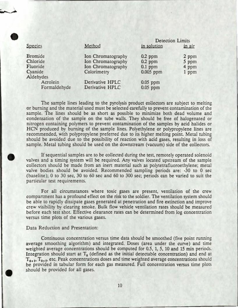
Species
Bromide Chloride Fluoride Cyanide Aldehydes
Acrolein Formaldehyde
Method
Ion Chromatography Ion Chromatography Ion Chromatography Colorimetry
Derivative HPLC Derivative HPLC
Detection Limits in solution in...rur
0.2 ppm 0.2 ppm 0.1 ppm 0.005 ppm
0.05 ppm 0.05 ppm
2ppm 5 ppm 4 ppm 1 ppm
The sample lines leading to the pyrolysis product collectors are subject to melting or burning and the material used must be selected carefully to prevent contamination of the sample. The lines should be as short as possible to minimize both dead volume and condensation of the sample on the tube walls. They should be free of halogenated or nitrogen containing polymers to prevent contamination of the samples by acid halides or HCN produced by burning of the sample lines. Polyethylene or polypropylene lines are recommended, with polypropylene preferred due to its higher melting point. Metal tubing should be avoided due to the possibility of reaction with acid gases, resulting in loss of sample. Metal tubing should be used on the downstream (vacuum) side of the collectors.
If sequential samples are to be collected during the test, remotely operated solenoid valves and a timing system will be required. Any valves located upstream of the sample collectors should be made from an inert material such as polytetrafluoroethylene; metal valve bodies should be avoided. Recommended sampling periods are: -30 to 0 sec (baseline); 0 to 30 sec, 30 to 60 sec and 60 to 300 sec; periods can be varied to suit the particular test requirements.
For all circumstances where toxic gases are present, ventilation of the crew compartment has a profound effect on the risk to the soldier. The ventilation system should be able to rapidly dissipate gases generated at penetration and fire extinction and improve crew visibility by clearing smoke. Bulk flow vehicle ventilation rates should be measured before each test shot. Effective clearance rates can be determined from log concentration versus time plots of the various gases.
Data Reduction and Presentation:
Continuous concentration versus time data should be smoothed (five point running average smoothing algorithm) and integrated. Doses (area under the curve) and time weighted average concentrations should be computed for 0.5, 1, 5, 10 and 15 min periods. Integration should start at T0 (defined as the initial detectable concentration) and end at T0• 1, T 0.s, etc. Peak concentrations doses and time weighted average concentrations should be provided in tabular form for each gas measured. Full concentration versus time plots should be provided for all gases.
10
' e
Concentration half-life should be determined for each gas as follows: After smoothing, the data is reprocessed and the natural log of the concentration is plotted against time. The decay portion of the plot must approximate a straight line for accurate half-life determination. (Significant slope changes, such as might be caused by generation of gas from a secondary fire, will render the calculated half-life invalid.) The plot is inspected and initial and final times are selected. A least squares fit is performed on the portion of the plot selected and the slope of the line is determined. The slope is the half-life in minutes or seconds, depending on the units of the abscissa. The half-life should be presented in tabular form and plots of the natural log of the concentration versus time should be provided.
Average pyrolysis product concentrations should be reported in tabular form for each sample collected. Particulate size concentrations, fractional weights and total weight should be reponed in tabular form and log-normal plots of cumulative percent versus panicle size should be prepared for each sample collected.
ACCELERATION INSTRUMENTATION
In the presence or absence of a penetrating event, injury might result when a force is delivered to a crewman's body by bulk motion of an ACV impacted by an energetic threat round. This is most likely to occur in a mine explosion if a soldier (usually the driver) is in contact with a vehicular surface violently deformed by the explosion. Most data applicable to this type of injury have been derived from automotive crash safety evaluation, military aircraft ejection seat design or aviator crash seat testing (64). Accurate accelerative force measurements and decellerative injury assessment are based upon automotive crash testing studies (65-66).
When required, the ballistic shock environment experienced by the crew should be measured by the use of instrumented Hybrid II or Hybrid III anthropomorphic simulators. The location, type and number of anthropomorphic simulators used on each test should depend on the shot line. No anthropomorphic simulators will be used at positions that fall within the primary spall cone on penetrating shots or on shots where significant accelerative loads are not expected.
The anthropomorphic mannequins should be standard Department of Transpertation automotive crash test dumnties, Hybrid II (pan 572 dummy) or Hybrid III, simulating a 50th percentile adult male in size, weight distribution, and joint articulation. The Hybrid II test simulators should be instrumented in accordance with the expected loading modes, for triaxial acceleration of the head, chest, and pelvis. The Hybrid II simulators should be used on shots where previous test data indicate a low probability that acceleration will approach danger levels. Force measurements on neck and spine do not need to be recorded as previous data indicate that shear and compressive forces in these regions are not significant (5). The Hybrid III dumnties should be used on shots where high accelerative loads are expected at the neck (compression, fore-aft bending, and shear), pelvic spine (compression and for-aft bending), and right tibia (axial compression). The legs of the Hybrid III mannequins should be positioned in typical leg positions appropriate
11
for each specific location. The simulators should be wearing uniforms and helmets appropriate for each specific location. A summary of the crew instrumentation should be listed in the detailed test plan prior to beginning the test.
Signal conditioning should be provided by either Pacific Instruments Model 8255 Transducer Amplifier, General Purpose Signal Conditioner, Precision Filters System 316 Programmable Signal Conditioner or equivalent equipment. Amplifier gain settings shoulc be based on expected acceleration levels for each shot. Data recordings should be provided by digital recording system with analog magnetic tape backup to reduce risk of data loss. All anthropomorphic mannequin transducers should be factory calibrated prior to installation and the data acquisition system field checked prior to each shot by use of voltage insertion tests.
Data should be presented as G versus time for a 200 msec window. Gauge identification, location, sensitivity, system gain and filtering information should be indicated on each time plot. Anthropomorphic mannequin acceleration data should be evaluated for accuracy before submission to medical evaluators.
INJURY ASSESSMENT CRITERIA
Prediction of hazards behind defeated armor is not an exact science. Once the environment inside the vehicle is · characterized, the data must be converted into a quantitative term (i.e. fractional incapacitation) representing the degree at which these events affect the soldier's ability to perform both his immediate and future mission. In some cases, a soldier will not be impaired in performing his immediate mission but will subsequently develop delayed injuries which will impair his performance in further missions. In other cases, a soldier might incur some immediate incapacitation but no delayed effects. The following criteria represent the best criteria to date and will be revised as better data are developed.
BLAST OVERPRESSURE INJURY CRITERIA
Primary blast injury is limited to the air containing structures of the body, i.e. the lungs, gastrointestinal tract and ears. Blast injury occurs as a result of an incident pressure wave directly loading the body (7-13). The resultant loading is distributed over the entire body surface and depends on the body's orientation to the incident wave (14-16). The exposure conditions which result in primary blast injury have been roughly determined; however, the precise injury mechanisms are not clearly understood (13).
A complex pressure wave occurs inside an armored vehicle defeated by an antitank round (Figure 1). There is an initial fast-rising wave emanating from the point of penetration. Other shocks are superimposed, emanating from the jet transversing the vehicle's interior, the exit site penetration and multiple internal reflections. After several
12
•
milliseconds, a quasi-static pressure might occur due to beating of the vehicle's crew space air and the accumulation of combustion products. This quasi-static pressure depends upon how rapidly venting occurs through breaks in the vehicle's integrity. Potentially, additional blast events might occur from detonation of other explosive devices or vaporized fuel and/or hydraulic fluid {13).
Widely accepted injury criteria have been developed for simple freefield blast waves (17). These blast waves have been defined in tenns of peak pressure, A-Impulse and ADuration. However, the body's interaction with complex blast waves has not yet been completely defined. Extensive data to support injury criteria for complex wave environ.mc!nts do not exjst. As a result, blast injury assessments inside the reverberant space of a defeated armored vehicle must be related to the criteria developed for Friedlander blast waves. Although several methodologies have been suggested, none has proven satisfactory for all conditions (8,18-24). Two techniques were used in the Bradley LIT (4) but only one was recommended by U.S. blast biology experts for use in the Ml.LFT (5).
Based on the current understanding of the interaction between the body and blast waves, the "effective peak pressure" technique is recommended for assessing injury in a complex blast wave environment. First, the total positive duration is determined and an "effective peak pressure" is graphically interpolated (Figure 2). The total positive duration is likened to the A-Duration term of a Friedlander blast wave. The "effective peak pressure" ignores the random pressure spikes which do not significantly contribute to the overall impulse of the waveform. Pressure pulses are not corrected for transducer orientation relative to the direction of travel of the blast wave. In an ACV, gauge position and orientation relative to the recorded shock waves cannot be accurately determined, but the pressure reflections are already accounted for in the pressure trace itself (20,25). The "effective peak pressure" and duration are then compared to the Bowen pressure-duration injury criteria for a prone body where the long axjs of the body is parallel to the blast winds in a freefield blast wave environment. Because the "effective peak pressure" technique takes into account the total duration, quasi-static pressure is included in the injury predictions. Injury predictions with this technique have correlated well with injuries observed in studies where anesthetized large animals were exposed to complex blast waves from point source explosions in enclosures and from antitank round penetration of ACV. The absolute peak pressure/5 msec impulse technique was also used in the Bradley LIT but was not recommended for use in the Ml LIT (5). Although the two techniques rendered similar results in the Bradley LFT assessment, the 5 msec impulse technique is based on extremely limited data and is not accepted by recognized blast experts for use in complex blast wave environments.
In 1983, a panel of blast experts estimated incapacitation predictions in Friedlander blast environments ( 6). These guidelines were based on experimentally observed physical damage from Friedlander blast waves. Accordingly, affected soldiers are expected to be 1% incapacitated at cor ditions which result in threshold injury to the lung. Similarly, conditions that cause death in 1% of the exposed population are equated to 50% incapacitation. An exposure lethal for 50% is assumed to cause 99% incapacitation of the exposed population. Intermediate degrees of incapacitation are estimated assuming a log normal probability distribution based on these three points. The injury predictions determined from
13
• application of the "effective peak pressure" technique are applied to this curve to predict levels of fractional incapacitation.
The wearing of a Kevlar ballistic vest has been shown to increase both mortality and morbidity for large animals in a strong blast environment and to increase intrathoracic pressures in humans at low overpressure levels (26-27). This effect has also been demonstrated in complex wave animal experiments (20). Estimates based on limited animal experiments with simple waveforms have indicated that the use of a ballistic vest reduces the blast level necessary to cause a certain level of mortality by about 25%. However, ACV crewmen wear a Kevlar ballistic undergarment rather than the bulky ballistic vest. The ballistic undergarment has not been evaluated for its effect on blast injury but is expected to be less hazardous than the ballistic vest because it is lighter (1.7 kg versus 2.9 kg). In order to estimate the effects of protective clothing on blast injury, the "effective peak pressure" is assumed to increase by 33% when the ballistic vest is worn and by 17% when the ballistic undergarment is worn.
A high incidence of eardrum rupture was assessed in the Bradley LFf ( 4 ). Eardrum rupture was not assessed in the M1 LIT (5) because it was determined that eardrum rupture would be unlikely given the standard use of the CVC helmet in the M1/M1A1. It was further determined that eardrum rupture itself should not be considered incapacitating. Even though temporary hearing decrements are expected from ACV armor penetrating events, no means are currently available to estimate the degree of hearing loss nor the potential decrement of soldier performance following a blast event (28-30). Animal research is underway to determine hearing decrements resulting from impulse noise; however, the effects of hearing loss on soldier function must be operationally defined.
THERMAL INJURY CRITERIA
Accurate prediction of crew survivability from fires within ACV is difficult because of complex interactions between the thermal environment, biologic response, and clothing protection (31-32 ). This report addresses the prediction of second degree (or worse) burns. The degree of incapacitation following burns is estimated via the Edgewood Arsenal Special Report EB-SP-76011-7 (33).
After penetration of an ACV, it is assumed that the first ten seconds are critical to the risk of developing thermal injury. A significant temperature elevation beyond this time would compel the crew to evacuate the vehicle, unless they could control the fire. Slowly developing thermal events could be identified by the crew, who would then jettison the burning material, control the fire with hand held fire extinguishers or evacuate.
The best measurable, environmental correlate of bum potential is heat flux calorimetry (34 ). The Bradle. · LFf did not measure this parameter ( 4 ). However, in the Ml LFT, heat flux measuren ents were taken which allowed the summation of radiant, conductive and convective thermal loads (5). The source and duration of the thermal exposure were found to be quite important. In the BFV report, the majority of the heat generated in armor penetrating events came from convective and long-duration, infrared
14
energy (4). In the M1/M1A1 test, thermal energy above 3.9 cal/cm2 delivered over a few seconds to unprotected skin was predicted to cause second degree burns (5).
Exposed calorimeters placed at each crew member's face and waist region should be used to assess burns to unprotected areas of the face and hand by directly applying the 3.9 cal/cm2 criterion for the initial 10 seconds measured. The simplest method to assess burns under clothing is to use additional calorimeters located beneath clothing in the chest and calf regions and directly apply the same criteria.
Burn criteria using free air temperature correlates loosely with heat flux criteria (31,35,36). Continuous free air temperature measurements are made at calf, waist and eye level for all crew positions. Free air temperatures and exposure times are related to second degree bum predictions for exposed bare skin by using the time integral of measured air temperature (T m) less body temperature according to the following equation (37):
toJ T1 = (T m - 37) dt (in degrees Centigrade)
Second degree burns to bare skin are predicted if the integral of temperature over 10 seconds exceeds 1315 °C-sec (2400 °F-sec) (37). Since convective and conductive heat transfer are nearly linearly correlated with free air temperature, the temperature-time integral should also be linearly related to the measured heat flux.
Unless clothing catches fire, any type offers some protection in a brief thermal exposure (38-40). However, in a significant thermal environment, no presently used battlefield garment will resist ignition for longer than 10 seconds ~41). Either BDU or Nomex plus either an air space or an undershin affords 5.3 cal/cm of protection, which protects the skin by a factor of 2.5 (37). This degree of protection factor was also used for helmet, goggles, boots, ballistic vest, etc. even though these materials are expected to protect more than clothing (37). To predict second degree burns beneath clothing, 5.3 cal/cm2 is added to 3.9 calfcm2 and the 10 second temperature time-integral is multiplied by the protection factor. For example, if the measured heat transfer exceeds 9.2 cal/cm2
or if the value of the corrected integral exceeds 3300 °C-sec (6000 °F-sec), second degree burns are likely (37).
The above described methodology was judged reasonable by a group of bum expens ( 42). A thermal equivalency chart comparing the time-temperature integral and heat transfer methods is presented below. Other units of heat transfer measurement have been reported (37) and are as follows.
15
Time-Temp Integral Centigrade Fahrenheit
E"l'osed Skin
1300 °C-sec 2400 °F-sec
Under Clothing
3300 °C-sec 6000 °F-sec
Heat Transfer Calories Joules BTU Watts-sec
3.9 cal/cm2 9.2 cal/cm2
16.3 Jjcm2 38.5 J/cm1
14.4 BTU /fr 33.9 BTU /fr 1.63 • lOS W-sec/m23.85 • lOS W-sec/m2
Given the occurrence of a skin burn by either the integrated air temperature-time or deposited heat flux methods (or both), the associated incapacitation is estimated by using the procedure outlined in Edgewood Arsenal report No. EB-SP-76011-7 (34). Incapacitation from skin burns is considered to be a result of a disability which affects the eyes or one or more joints. An assessment is made by associating a measurement location with one or more of the five major anatomical sites for which local effect information are available. This enables a disability estimate to be made for the affected area which is then translated to the probability of incapacitation given a hit (P(I/H)) by multiplying by a conversion factor. Disability to incapacitation conversion factors take into account the relative tactical importance of each site with respect to typical tasks associated with the assault military stress situation. Since conversion factors specifically for ACV crewmen do not exist, those for the infantry assault role are used due to similarities between the ACV crew and infantry soldier roles with respect to requirements for limb function. For consistency with P(I/H) assessments for fragment wounding, burns are evaluated at five minutes post injury.
The following relationship is assumed to exist between the various combinations of measurement locations and applicable sites:
Location of Significant Measurement
Eye Waist Calf Eye+ Waist
Eye + Calf
Waist +Calf
Eye + Waist + Calf
16
Body Areas Represented
Periorbital, Hands Elbows, Hands, Knees Ankles, Feet, Hands Periorbital, Elbows, Hands
Knees Periorbital, Hands, Ankles,
Feet Elbow, Hands, Knees,
Ankles, Feet Periorbital, Elbows, Hands,
Knees, Ankles, Feet
Note that the hands are always included to account for reflex movement to affected areas. Burns predicted for the elbows, hands or knees are considered to exist circumferentially as opposed to only one surface. To allow calculation of systemic effects (over and above site disabilities) a burn predicted for any particular region (Eye, Waist or Calf) is assumed to apply to fully one-third of the body's surface area. Similarly, two or three such measurements translate, respectively, to two-thirds, or all or the body's surface area.
To summarize the steps involved in the calculation of a burn P(I/H) the following steps are required:
1. Determine the percent disability for each affected site for the 30 sec to 5 min time frame.
2. Convert site disability to incapacitation by applying the conversion factor for the assault combat role.
3. Add in the systemic effects based on the fraction of the total body area burned.
4. Combine the site estimates to produce an aggregate P(I/H).
For convenience, second degree burn induced P(I/H) for a 30 sec to 5 min postinjury time period for various combinations of anatomical sites are shown in the following table. Given that second degree burns are predicted for the measurement location shown. from either thermocouples or calorimeters, the indicated P(I/H) represents the incapacitation that could be expected to result. Bums to the "feet" include the soles. Bums of elbows, hands and knees are assumed to be circumferential. Since the calculated incapacitation values depend not only on the instrumentation configuration and assumed tactical role and post injury time, other values are possible using the data provided in references (34 ).
TOXIC GAS INJURY CRITERIA
Toxic gases are generated in a penetrated ACV by a variety of mechanisms. A shaped charge jet will combine atmospheric nitrogen and oxygen to form NO and N02 (47-49). Burning propellant will release NO, N02, CO and C02 ( 4 ). Thermal decomposition of the Halon 1301 fire suppressant will form HF and HBr (4). Burning plastics might release HCl, acrolein, formaldehyde, and/or HCN (4). It is unrealistic to expect that levels of these gases will remain below concentrations generally considered safe by civilian standards. However, since these events only occur in combat, it is reasonable to accept some risk of minor injury in exchange for the protection afforded by the vehicle and its AFES. Avoiding incapacitation of soldiers is the primary mission. That is, when evaluating survivability in combat, levels of hazard and injury should not be equated to civilian exposure limits which are necessarily conservative because of their regulatory nature.
Given the complex interaction between severity of effect, ct,ncentration, variety of toxic species involved, time of exposure and individual breathing response, the existing toxicologic database does not allow an unequivocal statement of the relative hazard for most gases. The Army's interest in survivability studies such as this lies somewhere
17

between the civilian standards for the work place (low dose-long duration exposures) and lethality information. Estimates of hazard are given below based upon published data and animal experiments sponsored by the U.S. Army Medical Research and Development Command (MRDC).
The prediction of toxicologic hazard in these tests is made for exposures lasting up to 5 min after penetration. Although toxic gas levels are generally measured for 15 min, during the Bradley and M 1 LFr toxic fumes were virtually eliminated from the vehicle interior within 5 min by natural and/or forced ventilation (4,5).
For the purposes of injury prediction, soldiers are assumed to undergo strenuous exercise within hours of the toxic gas exposure. Increased ventilation has been shown to increase inhalation injury. If such exertion is avoided, perhaps for as little as 24 hours, the expected delayed casualty effect will be markedly reduced (50). Few data exist about measured tank crew work effort levels and ventilatory requirements. Two different studies (51,52) with two Ml tank crews indicate that commander, gunner and driver average about 2 to 3 times above resting oxygen consumption levels. The loader might ventilate at 4 times basal level during active fire missions. MIL-HBK-759A suggests a range of increased ventilation for various tasks, but for this criteria, ventilation is assumed to average 3 times the basal level of ventilation.
In the event the ACV is penetrated and there is a fire that has been successfully suppressed, crew members are expected either to don their individual protective mask attached to the collective ventilation system (CVS) or to exit the vehicle. Obviously, any significant fire which progresses after the AFES has discharged will force the evacuation of anyone who is not disabled. Fractional incapacitation predictions should made for the following 5 masking scenarios:
0 sec 30 sec ( +) 30 sec (-) 1 min 5 min
- Immediate or prior masking with CVS - 30 sec escape or 30 sec masking with CVS - 5 min exposure with 30 sec masking no CVS - 1 min escape or 1 min masking with CVS - 5 min exposure with no masking
This allows assessment of the time available before masking becomes essential. Soldiers breathing from a CVS prior to the penetrating event are completely protected from the toxic environment inside the crew compartment since the system delivers outside air to the crew. Soldiers are theoretically not as well protected if the CVS recirculates filtered crew compartment air to the crew. If toxic gas measurements are made from a CVS, the measurements made from that system must be factored into the toxic gas injury assessment for each crew member. If a soldier dons the mask attached to the CVS as soon as possible (about 20 seconds by doctrine (53)) and sustains a breath hold for that period (0 sec scenario), he will likely suffer no untoward effect from toxic gases. The 30 sec ( +) scenario assesses the hazard should the crewman decide to immediately e' acuate the vehicle (unmasked) or to don the mask attached to the CVS at 30 sec. The 30 sec (-) scenario describes the hazard should the CVS be non-functional and the crewmen mask at 30 sec when their individual filter canisters are unhooked from the CVS. This would expose
18
a crew member to unfiltered air for 30 sec as well as any toxins in the crew space which penetrate the filter (CO, some NO and N02) after masking. The 1 min scenario assesses the hazard should the crewman escape or don his mask attached to the CVS at 1 min. The 5 min scenario assesses the hazard of "worst case" where soldiers do not mask.
N02 is known to cause diffuse lung damage (chemical pneumonitis) resulting in incapacitating respiratory injury (54-56). Levels above 100 ppm are expected to cause some immediate discomfort with coughing and a burning sensation in the eyes and the chest. This might distract a soldier but would not be expected to prevent his taking appropriate survival or escape actions. The expected elevation of ventilation during exposure would increase the hazard proportional to the increase in ventilation above resting level. ~~DC supported research with rodents has shown lung damage begins at N02 exposures of 375 ppm-min (integral of concentration over exposure time) (57). N02 exposures of 1500 ppmmin resulted in a 30% increase in lung weight, a decrease in exercise capacity within one hour and very severe exercise limitation at 8 hours. At all levels tested (375 to 1500 ppmmin), exercising the animals maximally within an hour of exposure markedly worsened the degree of lung injury. At lower levels (e.g. 375 ppm-min) injury might not be manifested either histologically or in exercise performance for 4 to 8 hours. However, higher levels (1500 ppm-min) caused some immediate decrease in work performance. Both immediate (within one hour) and delayed (beyond one hour) effects should be considered. Immediate incapacitation, when predicted, probably occurs within the first 10 min following an exposure.
Assuming a tripling of ventilation, an exposure of less than 125 ppm-min prior to masking would be equivalent to the less than 375 ppm-min animal experiments and is thus considered to have a negligible risk of injury or incapacitation. An exposure between 125 and 250 ppm-min is considered to have some risk of impairment of function for individuals undergoing exhaustive exercise. Exposures above 250 ppm-min are considered to have a high risk of delayed incapacitation with exercise. Because a soldier in combat will most likely undergo significant exertion. this study assumes the risk of delayed incapacitation to be zero at 125 ppm-min, 100% at 375 ppm-min and linearly proportional between 125 and 375 ppm-min. No immediate incapacitation is expected below 250 ppm-min whereas all exposed individuals are assumed to be 100% incapacitated at 750 ppm-min. Intermediate degrees of incapacitation are linearly extrapolated. Incapacitation represents the fractional degradation in performance of physically and mentally demanding military tasks.
Minimal applicable toxicity data for isolated NO exposure exist in the civilian literature (12). Because NO oxidizes rapidly and spontaneously to N02, it has been very difficult to study pure NO toxicity without accompanying N02 toxicity. In most industrial (and experimental) settings NO is found in association with significant amounts of N02 (58). Therefore, NO toxicity has generally been equated with N02 toxicity, with NO and N02 being lumped as NOx as was done in the Bradley LFf (4). However, recent experiments supported by MRDC have shown differences between NO and N02 toxicity. Inhalation of lethal levels of NO does not cause pulmonary toxicity. Instead, inhalation of NO causes a chemical reaction in the blood resulting in the formation of nitrosylhemoglobin (NOHb) which rapidly transforms into methemoglobin (MetHb) (59).
19
The toxicity from exposure to CO and NO are likely to have similar mechanisms. Carboxyhemoglobin (COHb), NOHb and MetHb decrease the ability of the blood to carry oxygen. Recerlt experiments by MRDC have shown the kinetics of MetHb formation to be equivalent to those of COHb formation (59). That is, for equivalent exposures to NO and CO, equivalent amounts of JvietHb and COHb, respectively, are formed. Therefore, for the purposes of these tests, the dose of NO will be added to the CO dose to arrive at a CO dose equivalent.
A cumulative CO exposure of 37,250 ppm-min (mtegral of concentration over exposure time) .corresponds to a predicted 30% COHb concentration for someone doing heavy 'v.'Ork (60). Thi~ calculc:,tion is based upon a tripling of resting ventilation and corresponds to work effort level 3 of MIL-HBK-759A (61). A 30% COHb level would likely be associated with some impairment of visual and intellecreal function and levels above 30% COHb would be increasingly likely to render a soldier combat ineffective for a period of several hours. At about 50% COHb a soldier could lose consciousness, and by virtue of his inability to escape further exposure, become a fatality. A cumulative CO exposure of 62,750 ppm-min would be necessary to reach a 50% level. For the purposes of this study, a CO equivalent exposure (CO and NO) of 37,250 ppm-min will be assigned a 0% incapacitation and 62,750 ppm-min a 100% incapacitation with linear proportior.ality between these values.
Although C02 ha'\ little intrinsic toxicity, its ievels should be kept below 3%. Above that level, C02 stimulates respiration and, through an increase in ventilation, might potentiate the toxicity of other toxic gases. For this study, a 3% or greater concentration of C02 which lasts for longer than une minute is expected to doubie the inherent toxicity of all other gases (CO, NO, N02, HF, HBr, HCl, HCN).
The AFES in all ACV contains Halon 1301. As a consequence of its fire extinguishing mechanism, toxic pyrolysis products are formed as an essential chemical step. The liberation of HF and HBr in some quantities are unavoidable. The levels of these acid gases (HF & HBr) are affected by the Halon distribution, concentration, tire intensity and the total time to fire out. HF and HBr are very reactive gases and might exceed levels causing cough and eye irritation in a clt>sed space. The use of personal protective masks is a...;;surned to be necessary if the crew is to rernaiu in the tank. The ASC Carbon used in US filters is des;gned to remove acid halides and therefore no toxicity is expected from these gases (or HCI) once the mask is donned.
1l1e toxicity of exposures to rela:ively high levels of HF a11d HBr for short periods (less than a minute) is unknown a11d is the subject of wntinued research. These acid gases are highly water soluble and, at least ai. low levels, are efficiently scrubbed from inspired air. The mechanisms of injury from halide gas exposures are unclear, but nw.ssive acute exposures appear to be principally pneumotoxic and to produce pulmonary injury similar to N02• Rodent st,Hlies have shown the LC50 (concentration necessary to produce lethality in 50% of animab exposed) for HF to be 4970 ppm for a 5 min exposure in rats, 6247 ppm for 5 min in mice and 4327 ppm for 15 min in guinea pigs (62). Indications from one primate study are tha.t monkeys are more resistant to HF with a one hour LC50 of 1774 ppm whereas a similar effect for rodents v:as observed to range from :140-1310 ppm.
20
• Pending the results of the ongoing MRDC research, the 5 min human LC50 is assumed to be the lowest lD50 animal exposure level (4970 ppm), which is equivalent to a 24,850 ppmmin integrated dose. Since N02 data show a ratio of 3% between the threshold for incapacitation and the 5 min LCSOt this report assumes the same proportionality for HF. This delayed incapacitation is expected to begin at 746 ppm-min and be 100% at 2237 ppm-min. The extremes of immediate incapacitation would be 1491 and 4473 ppm-min. The inherent toxicities of HF, HBr and HCl are assumed to be similar and the measured levels of each will be added together for this analysis.
Concentrations above 100 ppm HF are quite irritating (62). However, extremely irritating atmospheres of HCl have not inhibited complex escape maneuvers in primate studies. Environments having a combination of HF and HBr (and HCl) above 100 ppm would most likely cause some coughing and possible visual impairment due to tearing until the mask is donned. However, due to the variability of the complex environment and the lack of information on the amount of irritation necessary to estimate incapacitation, no incapacitation is assessed based on irritation alone.
Toxicity from Halon 1301 is not a problem when average levels are kept below 7% for up to 15 min (63). Human exposures up to 14% have been tolerated for brief periods without ill effect. Levels of Halon decrease rapidly due to bulk ventilation of the vehicle interior. Should levels of Halon of 10% or greater persist for more than a minute after AFES discharge, the circumstance should be noted in the results section but no incapacitation should be assessed. The protective filter is predicted to convey Halon unimpeded.
Acrolein, a combustion product of some plastics, is very irritating to mucosal surfaces and causes delayed pulmonary toxicity very similar to that of N02 (64). For mice, the one min LC50 is reported as 875 ppm and the 10 min LC50 as 175 ppm (1750 ppmmin). By applying the 3% proportionality between threshold and short duration LC50 observed for N02, some incapacitation above exposures of 26 ppm-min of acrolein can be expected. This is just five times the exposure dose which would be experienced by exposure of an individual to the 5 ppm-min STEL (Short Term Exposure Limit, 0.3 ppm for a 15 min occupational exposure limit).
Another principal irritant, formaldehyde, might be released when certain polymers are burned and has a STEL of 2 ppm (65). As with Acrolein, exposures in excess of five times the STEL cumulative exposure (150 ppm-min) are assessed as having some acute hazard.
HCN, a product of combustion of some plastics, exerts a potent inhibitory effect on oxidative cellular metabolism which can be fatal (cyanide poisoning) (66). Brief exposures to atmospheres greater than 270 ppm can be fatal while exposures of 45 ppm can be tolerated for an hour without ill effect. This does not account for the possibility of injury enhancement with increased ventilation. For the purposes of this criteria, any one minute exposure average in excess of 90 ppm is considered immediately incapacitating. Over the five minute evaluation period, total exposures of 75 ppm-min are considered to be the threshold of incapacitation, and 225 ppm-min is considered 100% incapacitating.
21
The size and quantity of airborne particulates might be important to understanding the toxicity of this environment. Respirable particles (0.5 - 10 microns) might carry some adsorbed toxic species (e.g. acid halides) and deposit them in distal portions of the lung, thereby increasing the toxicity of some species normally removed in the upper respiratory tract. However, this enhancement of toxicity is expected to be rather small given the early masking doctrine, the total concentration necessary to cause injury, the expected mechanisms of injury and the body's normal defense breathing pattern during exposure to acrid environments. Use of the personal protective mask is expected given the nuisance effects of the aerosolized particles, and its filter would remove all particulates from the inhaled air. Although published nuisance exposure limits for particulates are available, they are based upon irritative factors for workers exposed throughout a full working day. Threshold injury criteria for an acute exposure to inert particulates are not available, and injury enhancement from the carrier phenomenon can not be defined because the amount and type of toxic species adsorbed onto inert particles of a respirable size are not known. The large amount of airborne particulates and vapors produced in a behind armor event makes exact characterization of particle size and concentrations unlikely. Particulate data will be useful in future medical research investigating the effects of particulates in these environments, but in this criteria no incapacitation is assigned for particulates.
ACCELERATION INJURY CRITERIA
A high intensity explosion (penetrating or nonpenetrating) might transmit accelerative forces through the armored vehicle structure causing soldier injury. Mechanisms of injury are ( 1) direct impingement of a vehicle part onto a body part (2) force loading the body through the vehicle's seat, (3) displacement of the soldier into a vehicle part or (4) trauma from displaced objects. In both the Bradley and Ml LIT, the incidence of acceleration injuries was minimal (4,5). For this reason the authors suggest limiting the measurement of acceleration/deceleration effects except in certain instances.
Human tolerance levels have been established experimentally and have been summarized in the Society of Automotive Engineers Information Report (SAE J885) (68). Predictive models for acceleration injuries in seated individuals can be applied to armored vehicles, as long as the same injury assessment technology is used.
Injury assessment measurements of mechanical responses have used the Part 572 Anthropomorphic Test Device and its improved successor, respectively known as the
• Hybrid II and Hybrid III dummies. The Hybrid II dummy measures triaxial accelerations in the head, chest and pelvis. Additionally, the Hybrid III dummy measures forces and moments in the cervical and lumbar spine and lower extremities. Use of these devices in evaluating and certifying new automobiles was mandated in the Federal Motor Vehicle Safety Standard (FMVSS 208). Injury assessment criteria translate engineering measurements of force, acceleration, and deflection (obtained from transducers mounted in the test surrogate) into probabilities of injury occurrence.
22

To assess acceleration injury potential in military armored vehicles, one or two fully instrumented dummies are placed in positions expected to receive significant accelerative loads (e.g. driver for mine shots) but outside the anticipated path of penetration. Accelerative forces at other crew positions are inferred from knowledge of the shot conditions (threat, angle and point of penetration, etc.), comparison to the results of similar shots if available and review of vehicle and plywood mannequin damage reports. Acceleration injuries in other crew positions should be evaluated on a shot by shot basis whenever measurements on the instrumented anthropomorphic dummy indicate injurious force levels.
The risk of head injury is assessed using the automotive industry's standard Head Injury Criteria (HIC) and applying the results to published probability of injury criteria (70). The HIC is a pan of FMVSS 208. Alternately, acceleration in excess of 150g sustained for greater than 2 msec is expected to cause a concussion with immediate and complete incapacitation for military tasks.
Neck injury assessment criteria were based on motor vehicle experimentation. Neck shear moments of > 190 N.m forward flexion, >57 N.m rearward extension of > 105 N.m lateral bending were predicted to cause immediate incapacitation. Additional injury assessment criteria include measurements of tension, compression and shear forces. Any force > 1 kN lasting > 30 msec is considered to cause immediate incapacitation.
Chest injury criteria are based upon deceleration following frontal impact with significant thoracic deformation (i.e. steering wheel injuries) (71,72). Chest accelerations of 40g sustained for more than 7 msec are assessed as having a high risk of thoracic trauma and are scored as completely and immediately incapacitating for military tasks. Recent studies have shown lung injury with minor chest wall displacements when the chest velocity (and acceleration) are large. This "blast-like" lung injury without rib fractures has been discussed above.
Criteria for lower spinal injury are derived from (1) US Army aircraft seat crash testing and are based on spinal loads and moments and from (2) the Dynamic Response Index based on aircraft ejection seat data in which spinal loads were inferred from pelvic accelerations (67). The two assessment criteria agree closely. Specifically, forward (longitudinal) accelerations in excess of 40g sustained for more than 7 msec or lateral or upward (vertical) accelerations in excess of 23g lasting more than 7 msec are considered to cause immediate and complete incapacitation for military tasks. Assessment of spinal bending moments predicted lower spinal injury with forward flexion > 1,235 N.m, rearward extension > 370 N.m or lateral bending > 675 N.m.
Lower extremity injury predictions are based on the strength of the tibia and femur under various loading modes (73,74). Any axial compressive force of greater than 1250 pounds for any length of time or 900 pounds acting for longer than 10 msec is evaluated as causing a fracture. The critical force levels are linearly interpolated between 2 and 10 msec. Leg fracture predictions are assumed to affect to both legs simultaneously and are therefore expected to cause complete and immediate incapacitation for military tasks.
23
FlASH INJURY CRITERIA
Three types of optic injuries might result following penetrating events inside ACV.
1. Permanent retinal injury (scotoma) might result from viewing an intense source emitting light in wavelengths of 400 to 1400 run at an integrated luminance above 2.6 Jfcm2sr for 5 msec. Although not entirely equivalent, this value converts to 520 Wfcm2
•
2. Corneal photodermatitis (welder's flash) and skin erythema (sunburn) might be caused by actinic ultraviolet radiation in wavelengths of 200 to 320 run and luminance above 10 mJfcm2sr. Such injuries occur several hours after events characterized by very high levels of radiant energy. Therefore these injuries are considered improbable and not immediately incapacitating.
3. Temporary flashblindness (afterimage) might result from viewing a brilliant flash source emitting light in the 400 to 700 run wavelengths.
The degree of impairment is a function of the intensity of the object viewed, the time elapsed from flash, the flash intensity, the size of the flash, the distance of the flash from the eye and the condition of the eye at the time of the flash (e.g. dark versus sunlight adapted). In most circumstances, surviving crew members would not be positioned to look directly at the flash without being affected by other more injurious effects of the penetration. Luminance measurements in the Bradley lFf showed flash blindness could last up to 3 sec in daytime and up to 6 sec at night ( 4 ). Approximately two minutes is required to fully recover to dark adaptation levels which existed prior to the flash. Flash blindness occurring in any ACV could be expected to be no worse than in the Bradley, where the effect was said to be equivalent to viewing the flash created by a Number 2 Sylvania flashbulb, and then only in soldiers looking directly at the point of entrance or exit of the penetrator. In summary, all studies have indicated that permanent retinal burns, photokeratitis and corneal surface burns are not expected to be a problem in ACV crew members surviving a penetration by an antitank round.
COMBINED INJURY ASSESSMENT
Reliable prediction of the synergistic effects of combined injuries cannot be assessed by current criteria. No criteria is available for estimating the expected increased fractional incapacitation caused by simultaneously occurring injuries. The probability of injuries occurring simultaneously can be calculated by subtracting from 100% the product of the probabilities of incapacitation for each injury. However, this statistical manipulation might underestimate a soldier's incapacitation because one injury is expected to magnify the incapacitation of another. Therefore, no attempt is made in this report to estimate the synergistic effects due to combined injuries. For this report, incapacitation from combined injury is assumed to be equal to the total P(I/H). Individual incidence probabilities are compiled without regard for physiologic interactions between individual injuries. The total
24

• P(I/H) is estimated using the formula:
P(I/H),o,al = 1 - (1 - P.)(l - P2)(l - PJ) ... (1 - P .)
where P. = the individual injury's probability of occurrence.
25

BIBLIOGRAPHY
1. O'Bryon JF. Live Fire Testing: The Legislation and Its Impact. ArmY Research. Development & AcQuisition Bulletin, pp. 1-3, 1987.
2. Kennedy DR. Improving Combat Crew Survivability. Armor, July 1983.
3. Kokinakis W, Sperrazza J. Criteria for Incapacitating Soldiers with Fragments and Flechettes. BRL Report No. 1269, Ballistic Research Laboratories, January 1965.
4. (C) Phillips YY, Ripple GR, Mundie TG, ~ Medical Evaluation of Nonfragment Injury Effects in the Phase ll Bradley Fighting Vehicle Live Fire Test, Blast Overpressure, Toxic Fumes, Thermal, Flash, and Crew Acceleration Injuries (U).
5. (S) Ripple, GR, Mundie, TG, Dodd, KT, ~ Medical Evaluation of Nonfragment Injury Effects in the M1A1 Live Fire Test (U)
BLAST OVERPRESSURE
6. Proceedings of Meeting of Blast Experts and Conference on Blast Wounding and Trauma. USABRL, Aberdeen Proving Grounds, MD, 19 Sept 1983.
7. Chiffelle TL, Jones RK, Richmond DR, Damon EG. The Biologic and Pathologic Effects of Blast Injury. Techrucal Report on Contract DA-49-146-XZ-055, 1966.
8. Clifford CB, Moe JB, Jaeger JJ, Hess JJ. Gastrointestinal Lesions in Lambs Due to Multiple Low-level Blast Overpressure Exposure. Military Med, 149(9): 491-495, 1984.
9. Dodd KT, Phillips YY, Yelverton IT, Richmond DR. Nonauditory Risk Assessment for Friedlander Blast Waves. In: Proceedings of the 9th Military Applications of Blast Symposium, 23-27 September 1985, VII.6.1-VII.6.24
10. Dodd KT, Phillips YY, Yelverton MS, Richmond DR. Nonauditory Risk Assessment for Friedlander Blast Waves. In: Proceedings of the Technical Cooperation Program's Third Workshop on Weapon Launch Blast Overpressure, June 1987, 231-252.
11. Phillips YY, Dancer A, Richmond DR. Nonauditory Effects of Repeated Exposure to Intense Impulse Noise. In: Applied and Basic Aspects of Noise Induced Hearing .LQss. Salvi R. ~. ed., In press.
12. Richmond DR, Damon EG, Fletcher ER, Bowen IG, White CS. The Relationship Between Selected Blast-Wave Parameters and the Response of Mammals Exposed to Airblast. Annals NY Acad Sci, 152(1):103-121, 1968.
26
e 13. White CS, Jones RK, Damon EG, Fletcher ER, Richmond DR. The Biodynamks of Airblast. Report DNA 2738T, 1971.
14. Dodd KT, O'Hair KC, Vander Vorst MJ, Yelverton JT, Phillips YY, Richmond DR. Analysis of Field Test Results of the Biophysical Response of Sheep to Blast Loading. In: Proceedings of the 10th Military Applications of Blast Symposium.
15. Dodd KT, Vander Vorst KJ, PhiJlips YY. Analysis of Field Test Results on the Internal Mechanical Response of Sheep to Blast Waves. In: Proceedings of the Technical Cooperation Program's Third Workshop on Weapon Launch Blast Overpressure, June 1987, 201-213.
16. (C) Schmidt EM, Heaps CW, Jacobson JR. Blast Overpressure Internal to Vehicles Perforated by Shaped Charges. US Army BalJistic Research Laboratory, Aberdeen Proving Ground, Maryland, February 1985.
17. Brown JR. Noise-induced Hearing Loss Sustained During Land Operations in The Falkland Islands Campaign, 1982. J Soc Occup Med, 35:44-54, 1985.
18. Richmond DR, Yelverton IT, Fletcher ER, Phillips YY. Biologic Response to Complex Blast Waves. In: Proceedings Ninth International Symposium Military Application of Blast Simulation (MABS 9), 1985.
19. Richmond DR, Kilgore DE. Blast Effects Inside Structures. In: Proceedings of the Second Conference on Military Applications of Blast Simulators. November 2-5, 1970, Naval Weapons Laboratory, Dahlgren, Va., pp 781-804, DNA-2775p, Defense NucJear Agency, Department of Defense, Washington, D.C., May 1972.
20. Richmond DR, Yelverton JT, Hicks W, PhiJlips, YY. Biological Effects of Complex Blast Waves from Explosions Inside an EncJosure. Results Report, Interagency Agreement 82-PP-2800.
21. Richmond DR, Yelverton JT, Berkbigler LW, Moore LM, Phillips IT. Blast Effects Behind Armor. In: Proceedings Fourth T ACOM Ann or Coordinating Conference for Light Combat Vehicles, 31 March 1988 (In Publication).
22. Y elvenon JT, Richmond DR, Fletcher ER, Phillips YY, Jaeger JJ, Young A Bioeffects of Simulated Muzzle Blasts. In: Proceedin2s of the Eighth International Symposium on Military Application of Blast Simulation. Spiez, Switzerland, 20-24 June 1983.
23. Jonsson A Experimental Investigations on the Mechanisms of Lung Injury in Blast and Impact Exposure. Linkoping University Medical Dissertations, No. 80, 1979.
24. Stuhmiller JH, Chuong CJ, Phillips YY, Dodd KT. Computer Modeling of Thoracic Response to Blast. In: Proceedin2s of the 5th International Wound Ballistics Symposium. In Press, Journal of Trauma.
27
25. (C)-UK Cooper GJ, Maynard RL, Evans V~ Kenward CE. The Secondary Effects of the Defeat of Armour by Shaped-Charge Warheads: Summary of the Biological Trials at CDE, 1981-1982. CDE Technical Note No. 431, Chemical Defence Establishment, Parton Down, Salisbury Wilts, February 1986.
26. Phillips YY, Mundie TG, Yelverton JT, Richmond DR. Cloth Ballistic Vest Alters Response to Blast. J Trauma, 28:S149-S152, 1988.
27. Young AJ, Jaeger JJ, Phillips YY, Yelverton IT, Richmond DR. The Influence of Clothing on Human Intrathoracic Pressure During Airblast. Aviation Space Environ ~. 56:49-53, 1985.
28. Cooper GJ, Maynard RL, Cross NL, Hill JF. Casualties from Terrorist Bombings. J Trauma, 23(11):955-967.
29. James DJ, Pickett VC, Burdett KJ, Cheeseman A The Response of the Human Ear to Blast. Part 1: The Effect on the Ear Drum of a "Short" Duration, "Fast" Rising Pressure Wave. Joint A WRE/CDE Report No. 04/82, June 1982.
30. Pahor AL. Blast Injuries to the Ear: An Historical and IJterary Review. J Laryngol Otology, 93:225-251, 1979.
11-IERMAL EFFECTS
31. Kilminster DT. A Model to Predict Human Skin Burns. USA Ballistic Research Laboratories Memorandum Report No. 2426, Dec, 1974.
32. Kilminster DT. A Method to Predict Human Skin Burns. USA Ballistic Research Laboratories Memorandum Report No. 2426, Dec 1974.
33. Evans El, ~ Flash Burn Studies on Human Volunteers. Recent Adv Surg, 17:239, 1955.
34. Biomedical Evaluation of Thermal Effects. In: Handbook of Human Vulnerability Criterion. Edgewood Arsenal Special Publication EB-SP-76011-7, May 1976.
35. Knox FS. Mathematical Models of Skin Burns Induced by Simulated Post Crash Fires as Aids in Thermal Protective Clothing Design and S~lection. USAARL Report No. 78-15, June 1978.
36. Assessment of Flame and Incendiary Munition Effects (Project HEAT WAVE) Cal Report NO. GM-2168-G-1 Sept 66. Unclassified portion.
37. Stoll AM, ~ Relationship Between Pain and Tissue Damage Due to Thermal Radiation. J Appl Physiol, 14(3):373-382, 1959.
28
e 38. Ripple GR, Torrington KT, Phillips YY. Predicting Burns Behind Defeated Armor. In: Proceedings Fourth TACOM Armor Coordinating Conference for Light Combat Vehicles, 31 March 1988 (In Press).
39. Baba AJ, Schallhorn BP, Share S, Gaspar SM. Incidence of Skin Burns Under Contemporary Army Uniforms Exposed to Thermal Radiation from Simulated Nuclear Fireballs. HDL-TR-2084, Harry Diamond Laboratory Command, September 1986.
40. Knox FS. Bioassay of Thermal Protection Afforded by Candidate Flight Suit Fabrics. Aviat Space Environ Med, October 1979.
41. Morton JH, ~ Study of Flash Burns: The Protective Effects of Certain Fabrics. Surg Gynecol Obstet, 94:487-501.
42. Knox FS. How to Measure the Burn-Preventive Capability of Nonflammable Textiles: A Comparison of the USAARL Porcine Bioassay Technique with Mathematical Models. Burns, 5:19-29, 1979
43. Proceedings of the Burn Prediction Update Symposium, 20-21 May 1987, Walter Reed Army Institute of Research In Press, J Laryngol Otolo~, 1989.
TOXIC GAS HAZARDS
44. Buettner LC, tl..a1 Interim Report: An Empirical Evaluation of Individual Protective Filters Challenged by Toxic Gases Potentially Present in the Bradley Fighting Vehicle, US Army Chemical Research, Development and Engineering Center, Aberdeen Proving Ground, MD, June 1987.
45. Halon 1301 Fire Extinguishment Toxicity Program, Lyndon B. Johnson Space Center, White Sands Test Facility, Report No. TR-411-002, August 1985.
46. Tejada S. DNPH-Coated Silica Cartridges for Sampling Carbonyl Compounds in Air and Analysis by High Performance Liquid Chromatography, US Environmental Protection Agency, Research Triangle Park, NC., 1986.
47. (C)-UK Maynard RL, Cooper GJ, Cross NL, Aldous FAB, Evans VA, Kenward CE. Studies on the Pathological Effects of Brief Exposure to Mixed Oxides of Nitrogen Generated by Shaped-Charge Penetration of Armour. Chemical Defence Establishment, Parton Down, Salisbury Wilts, October 1983.
48. (C)-UK Cooper GJ, Pearce BP, Hollingdale-Smith PA. Joint UK/US Trials on the Measurement of Oxides of Nitrogen Within an AFV Test Rig Attacked by HEAT Warheads: 26 November - 7 December 1984. CDE Technical Note No. 750, Chemical Defence Establishment, Parton Down, Salisbury Wilts, March 1986.
49. (C)-UK Cooper GJ, Maynard RL, Evans VA, Kenward CE, Aldous FAB. The
29
Toxicity of Nitric Oxide with Particular Relevance to the Penetration of AFVs by Shaped Charge Warheads. CDE Technical Note No. 418, Chemical Defence Establishmen~ Porton Down, Salisbury Wilts, November 1985.
50. Lehnert BE, Wilson JS, Stavert DM. Exercise Potentiates Nitrogen Dioxide (N02)
Toxicity. 1987 Annual Meeting of the Society of Toxicology, February 24-27, 1987 Washington. D.C.
51. Unpublished data from US Anny Human Engineering Laboratory Protocol, Tank Crew Metabolic ·workload Study. Marsha Glum, Principal Investigator.
52. Torrington KT, Parmer D, Mundie TG, ~Ventilatory Requirements of Tank Crew Members During Simulated Battlefield Conditions. USAMRDC Technical Report, 1989.
53. Memorandum for Chief, Department of Respiratory Research, Date: 8 Oct 1987, from TSM Tank Systems, Headquarters, U.S. Army Armor School, Subject: M25/M25A1 Tank Mask Procedures.
54. Abraham WM, ~. Cardiopulmonary Effects of Short-Tenn Nitrogen Dioxide Exposure in Conscious Sheep. Environ Res, 22:61, 1980.
55. American Conference of Governmental Industrial Hygienists: "Nitrogen Dioxide." In: Documentation of the Threshold Limit Values for Substances in Workroom Nr, 4th ed., pp 305-306, ACGIH Printing Office, Cincinnati, 1983.
56. Carson TR, Rosenholtz MS, Wilinski IT, Weeks MH. The Responses of Animals Inhaling Nitrogen Dioxide for Single, Short-tenn Exposures. Amer Ind Hyg Assoc I. 23:457-462, 1962.
57. Lehnert BE, Wilson JS, Stavert DM. Early Lung Changes Following Acute Exposures to Relatively High Concentrations of Nitrogen Dioxide. 1987 Annual Meeting of the Society of Toxicology, February 24-27, 1987, Washington. D.C.
58. American Conference of Governmental Industrial Hygienists: "Nitric Oxide." In: Documentation of the Threshold Limit Values for Substances in Workroom Air, 4th ed., pp 301-302, ACGIH Printing Office, Cincinnati, 1983.
59. Lehnert BE. Unpublished data from USAMRDC Contract 85-PP-5855, Respiratory Tract Effects Following Acute Exposures to High Concentrations of Oxides of Nitrogen.
60. Coburn RF, Forster RE, Kane PB. Considerations of Phy! ;ological Variables that Determine the Blood Carboxyhemoglobin Concentration i.1 Man. J Clin Invest, 44:1899-1910, 1965.
61. MIL-HDBK-759A, Human Factors Engineering Design for Army Materiel, Section
30
e 3.7 Noxious Substances, 30 JUN 81.
62. American Conference of Governmental Industrial Hygienists: "Hydrogen Fluoride." In: Documentation of the Threshold Limit Values for Substances in Workroom Ajr. 4th ed., pp 223-224, ACGIH Printing Office, Cincinnati, 1983.
63. Cecich TF. The Use of Halons as Fire Extinguishing Agents. Professional Safety, pp. 28-31, January 1985.
64. Albin, TB. Acrolein, Handling and Toxicity. In: Acrolein, John Wiley and Sons, New York, 1962.
65. American Conference of Governmental Industrial Hygienists: "Formaldehyde." In: Documentation of the Threshold Limit Values for Substances in Workroom Air. 4th ed., pp 197.1-197.2, ACGIH Printing Office, Cincinnati, 1983.
66. American Conference of Governmental Industrial Hygienists: "Hydrogen Cyanide." In: Documentation of the Threshold Limit Values for Substances in Workroom Ajr. 4th ed., pp 222-223, ACGIH Printing Office, Cincinnati, 1983.
ACCELERATION EFFECTS
67. Simula Inc. Aircraft Crash Survival Design Guide, Volume II Aircraft Crash and Human Tolerance. Final report, No. USARTI..-TR-7922B, January 1980.
68. Human Tolerance to Impact Conditions as Related to Motor Vehicle Design. SAE 1885 APR80, Handbook Supplement HSJ885 APR80, 1900 Edition Society of Automotive Engineers, Warrendale, PA
69. Mertz HJ. Injury Assessment Values Used to Evaluate Hybrid ill Response Measurements. USG 2264 Part III, Attachment I, Enclosure 2, February 1984.
70. Haley JL, Shanahan DF, Reading TE, Knapp SC, Head Impact Hazards in Helicopter Operations and Their Mitigation Through Improved Helmet Design. In: Impact Injury of the Head and Spine, pp 549-577, Edited by C.L, Ewing~. C.C. Thomas, Springfield, II..., 1983.
71. Kroell C~ Allen SD, Warner CY, Perl TR. Interrelationship of Velocity and Chest Compression in Blunt Thoracic Impact to Swine II. SAE 861881, In: Proceedin~s of the Thirteenth Stapp Car Crash Conference, October 1986.
72. Menz HJ, Gadd CW. Thoracic Tolerance to Whole-Body Deceleration. SAE 710852, In: Proceedings of the Fifteenth Stapp Car Crash Conference November 1971.
73. Melvin JW, Stalnaker RL, Alem NM, Benson JB, Mohan D. Impact Response and Tolerance of the Lower Extremities. SAE 751159, In: Proceedin~s of the Nineteenth
31

74.
Stapp Car Crash Conference, November 1975.
Powell WR, Odala SJ, Advani SH, Martin RB. Cadaver Femur Responses to Longitudinal Impacts. SAE 751160, In: Proceedin2s of the Nineteenth Stapp Car Crash Conference, November 1975.
32
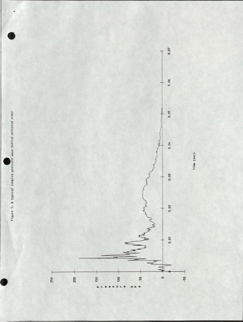
... ~ ... c:;
~ (.J -"' (.J -(.J
-c
~ .z:. ..8 (.J
> "' ::1:
-~ v (.J ... Q.
>( (.J
~ u
c u Q. >-... <
(.J ... :;) Ol ...
0
"' N
0 0 N
0
"' 0 0
0
"'
p
0
..... 0
0
.0 0
0
"' ~ 0
~
~ 0
.... 0
0
N
~ 0
-0
0
0
"' .
..... u (.J
"' t ,_
p r e s s u r e
e e the "Effective Penk Pressure" technique
Peak Pressure
"Effective Peok Pres!:urc"
Posittve Phase Duration
Time
Ouosi -Static Pressure
e "
DEPARTMENT OF DEFENSE ARMED FORCES EP IDEMIOLOGICAL BOARD
·~,.· .·.,, '•, ..... '• ! \ :il ~ . ~
~. , . -. '"''·... ..· ...... ......
• .-( E'ltEC..JTIVE SECRETARY Ll" "EC C'QPCES EPIOEMIOLC<ioCA. f ;:1"
::. < ' C i:. C " T H E' S U R G E 0 N G E t< E " llo •
CE D~~oR1ME NT Of THE' .aFM " ~109 LEESB U " G P I KE f 4 L L 5 C 1-4 Ll R C 1-t VA ~: 0 4 ' 3: 5 f ·
AFEB (1.5-1a) 89-2 26 May 1989
MEM>AANil.lM FOR 'IHE ASS~ ~ OF I:JE:FENSE (HFAI!IH ~) 'IHE SOR:iEX:N GENERAL, DEPARIMENI' OF 'mE ARMY 'IHE ~GENERAL, DEPARIMENI' OF 'mE NAVY 'IHE SUR:iEX::N GENERAL, DEPARIMENI' OF 'mE AIR FORCE
SL'"BJD:T: Rec:cmlendation on the Draft Tedmical EW.letin on Na1fragmentary Injuries Behin:l Defeated Ariior
1. At the request of the Arrrry SUrgeon General, the AFEB, in CCJnjunct.ion with its meet.i.rq of 17 February 1989, the AFEB considered a presentation by ~ Gary Jtiwle on the above topic ( erclosure) • SUbsequent to this presentation, an ad~ stu1y group of the Board, cha.i.red by Dr. Norton Nelsa1 evaluated the draft of the tedmical document erx:x:mpassi.n:J these matters. Mati::lers of the cx:mnittee in:::hrled Drs. Jdln D:lull, Arthur Dlbois arrl Gareth Green. 'Ihe ad hQ;;: cxmnittee foond the draft Ripple report to be an orderly presentation of issues as understocd by the group arrl detenni.ned that this report was a CXJnSistent arrl appropriate extension of earlier related t.c:pics on the Bradley Fight.in:J vehicle cxrsidered by the Board on 6 June 1987.
2. In consideration of the fi..n:l:irr;s of the ad hg; stu1y gro.Jp, the membership herein accepts their recx::mrerrlations arrl makes the followin) statement:
'mE "l'fXEllC'AL IXX."tlMEN1' OOI'LINDG 'mP! CRI"1'ERRA POR ES"l"'MM'MlI] ~ INJURIES BEHIND J:::E:F!'Am> MKJR REPRESEN1'S AN APimPRIM'E MD S'YS'l'EMM'IC APPR:l1CB af 'miS 'roPIC. mE OOARD PURfi1Ek ~ '1D OSB ~ »moJ. SOBJ'B:."1'S IN ANY cnn'INCDG 8'roDIES. FAILllRB '10 00 a> 1ll:X1ID tl'IJl'IMM'ELY RIS1t 'mP! ~ ar SUB.J'B:"1''lG BtlM1\N cxx::uPANrS OP MKil'!D VEHICLES 'ro SERIOOS INJ'URY MD ID.'m.
35
AFEB (15-la) 89-2
SUBJ'ECI': Reccmnen:iation on the Draft Technical &llletin on Nonfra~""ltr.:-; Injuri_es Be.~in:i DefeGted Anror
FOR '!HE ..;R:rl£0 FORCES EFIDEMIOr..cx;ICAL OClARD:
!HEDOORE E. ~, M.D. President, AFEB
· ~ies F\lrnished: Board Meui::lers 01, ~, lEAF SGP 01, Prev Med Di v, OISG-Dr\ 01, Prev Med Div, ~, USAF Dir, Clc:oJp Ill th & Prev Med Di v, BJMED-CN DASD (PA & Cl\) Otrlr, US Arrr.rj Med R&D Qrd Dir, Prof SVcs, OI'SG-Db. Dir, P~, ~, USAF Dep.rt:y O:!r, Fleet Readiness & SUpt, BJMED-O>l Dir, AFMIC AFMIC SUrgeon
36
RJBERI' A. WELlS, Rl.D. Cola1el, USA, MSC Executive Secretary
I •W
- PISTRIBUTION LIST
No. of Copies
5 US Army Medical Research and Development Command ATTN: SGRD-RMS Ft. Detrick, MD 21701-5012
12 Defense Technical Information Center (DTIC) ATTN: DTIC-DDA Cameron Station Alexandria, VA 22314
1 Library Walter Reed Army Institute of Research ATTN: SGRD-UWZ-L Washington, D.C. 20307-5100
1 Commander
I
US Army Materiel Command ATTN: AMCDE-XS 5001 Eisenhower Ave
• Alexandria, VA 22333-0001
2 Commander US Army TECOM Live Fire Testing Office ATTN: AMSTE-TA Aberdeen Proving Ground, MD 21005-5055
1 Commander US Army Combat Systems Test Activity ATTN: STEC-MA-P Aberdeen Proving Ground, MD 21005-5059
1 Commander US Army Combat Systems Test Activity ATTN: STEC-EN-PM Aberdeen Proving Ground, MD 21005-5059
1 Commander US Army Combat Systems Test Activity ATTN: STEC-DA-1 Aberdeen Proving Ground, MD 21005-5059
37
r
1
1
1
1
•
'
Director US Army Ballistic Research Laboratory ATIN: SLCBR-VR-1 Aberdeen Proving Ground, MD 21005-5066
Director US Army Aeromedical Research Laboratory ATIN: SGRD-UAS Ft. Rucker, AL 36362-5292
Director Live Fire Testing OUSD(a) ODDRe(T&E) Pentagon 1B473 Washington, D.C. 20301-3110
Institute for Defense Analysis Operational Evaluation Division ATIN: Dr. Benjamin Turner 1801 N. Beauregard St. Alexandria, VA 22311
38