wang, r-j., matthee, a., gerber, s., tlali, p.m., (2016...
TRANSCRIPT

This is a repository copy of Calculation of torque performance of a novel magnetic planetary gear
Article:
Wang, R-J., Matthee, A., Gerber, S., Tlali, P.M., (2016) Calculation of torqueperformance of a novel magnetic planetary gear, IEEE Magnetics Letters, vol. 7,issue 1, 1303805, 2016; ISSN: 1949-3088
https://doi.org/10.1109/LMAG.2016.2564948
Reuse Unless indicated otherwise, full text items are protected by copyright with all rights reserved. Archivedcontent may only be used for academic research.

Torque Performance Calculation of a Novel Magnetic Planetary Gear
Rong-Jie Wang1*, Alexander Matthee1, Stiaan Gerber1**, Pushman Tlali1**
1Department of Electrical and Electronic Engineering, Stellenbosch University, Stellenbosch, South Africa*Senior Member, IEEE**Member, IEEE
Abstract– In this paper, an efficient energy-based methodology is proposed for calculating the torque performanceof a novel magnetic planetary gear. To verify the proposed method and the gear performance, a prototype was alsoconstructed and experimentally evaluated. It shows good agreement between the predicted and measured torqueperformance. The new gear topology demonstrates higher torque capability than the common, flux-modulated magneticgear. However, the complex mechanical construction and the high loss at no-load remain as challenges.
Index Terms– Electromagnetics, magnetic gears, magnetic stored energy, torque calculation
I. INTRODUCTIONMagnetic gears (MGs) are receiving increasing attention
from both research institutions and industry. Different highperformance magnet gear technologies, such as flux modulated[Atallah 2001], harmonic [Rens 2007] and planetary [Huang2008] magnetic gears, have been proposed in the past 15 years.Recently, a new magnetic planetary gear has been proposedin [Davey 2016], which shows the potential of even highertorque capability than that of a flux modulated magnetic gear(FMMG). In this study, an efficient energy-based calculationmethod is proposed for predicting the performance of the newgear. A working prototype was developed and experimentallyinvestigated to validate the operating performance of the newgear and the proposed method.
II. MAGNETIC PLANETARY GEARSThe layout of a mechanical planetary gear consisting of
a sun gear, a ring gear and a carrier with planet gears isshown in Fig. 1(a). Typically, one of these three componentsis kept stationary while the other two components act as inputand output, respectively. The resultant gear ratio depends onthe pitch radii of the components, which are proportional totheir respective number of teeth, and on which component isstationary. The relationship between the number of teeth of thering gear (zr), sun gear (zs) and planet gear (zp) is governedby:
zr = zs + 2zp (1)
The general angular velocity relationship between the sungear (ωs), ring gear (ωr) and planet carrier (ωc) is:
ωszs + ωrzr = ωc(zs + zr) (2)
The operating principle of MGs is very similar to mechanicalgears except that all the gear teeth are replaced with perma-nent magnets (PMs) [Gouda 2011]. For a common magneticplanetary gear, the pole-pairs of the sun, ring and planet gearsgenerally satisfy the same relationship as in eqn. (1). The polepitch of each MG component should be the same and thenumber of planet gears should be carefully selected to maintainsynchronization [Huang 2008]. For example, a magnetic plane-tary gear with zr = 12, zs = 6 and zp = 3 is shown in Fig. 1(b).
(a)
Ring gear
Sun gear
Planet gear
(b)
Fig. 1. Layout of (a) a mechanical, and (b) a magnetic planetary gear.
Consider one arrangement where the planet carrier is station-ary and the sun gear is the input gear. The planet gears simplyrotate about their own axes at a rate determined by the ratioof the number of teeth (zs/zp). The rotation of the planet gearscan, in turn, drive the ring gear in a corresponding ratio (zp/zr).Thus, with a stationary planet carrier (ωc = 0), the resultantgear ratio (Ge) of the planetary gear is simply (−zs/zr) [Niguchi2012], where the negative sign indicates that the sun and ringgears rotate in opposite direction.
For mechanical and common magnetic planetary gears withstationary carriers, Ge is still related to zp, because of eqn. (1).By making use of flux modulation effects, unconventional mag-netic planetary gear designs can be realized, where the planetgears can be replaced by either (zr + zs) ferromagnetic polepieces [Atallah 2001] or the same number of free-rotating flux-switching planet magnets [Davey 2016]. The same angularvelocity relations as in eqn. (2) can be obtained [Gouda 2011].Figure 2 illustrates the layout of the new magnetic planetarygear topology, where the ring and sun gears contain 21 polepairs and 2 pole pairs, respectively, and the planet carrier has23 freely-rotating 2-pole hollow planet gear magnets to enhancethe flux modulating effects [Davey 2016].
III. TORQUE PERFORMANCE CALCULATIONSince each planet gear deals with the torques from both
sun and ring gears, a unique stable position exist for eachplanet gear, which corresponds to the minimum stored energyas shown in Fig. 2. Obviously, the calculation of the torque

x
y
θ
θi
Fig. 2. The new magnetic gear topology showing the magnetizationvector angle θi of a planet gear relative to its position angle θ.
characteristics of the magnetic planetary gear would require theknowledge of the angular positions of these planet gears. Al-though two torque calculation methods are proposed in [Davey2016], they both have relatively slow convergence performance.In this paper, an energy-based finite element (FE) calculationmethod is proposed, which assumes that:
• The total magnetic stored energy in the gear should beminimum (or maximum magnetic co-energy) when all theplanet gears settle in their equilibrium positions
• There exists a unique balanced angular position for eachplanet gear to meet with the previous condition, where thenet torque on a planet gear is zero
A. FE Modeling Techniques
Since there is no magnetic periodicity that can be exploitedin the FE simulation of this gear design, the full gear needs tobe modeled. If the rotational movement of each planet gear isincorporated into the FE modeling, it would drastically increasethe computational efforts and the complexity of the FE model.A simpler approach would be to parametrize the magnetizationvector, ~M(θi), for each planet gear and rotate these vectorsinstead, while keeping the mesh constant. In this case, there are23 localized magnetization vectors (one for each planet gear),which are used as variables. The angles of these vectors (θi)can be found by solving an unconstrained optimization problemas follows:
F = MINWen[ ~M(θi)], i = 1, 2, ... , 23 (3)
where the magnetic stored energy, Wen, is computed by inte-grating the energy density of the whole 2D FE model:
Wen =
∫∫H · dB dS (4)
A flowchart of the computation process is shown in Fig. 3, inwhich VisualDOC, a multidisciplinary optimization software fromVR&D, is used as the optimization environment and it coupleswith a 2D FE program to find the angles of magnetizationvectors. To improve the computational efficiency and reduce therisk of converging to a local optimum, several preconditioningtechniques were implemented, i.e.:
(i) presetting the magnetization vectors M(~θi) radially ac-cording to the sun gear’s flux pattern,
(ii) presetting M(~θi) using the angles obtained from the flux-tracing FE run with non-magnetized planet gears, and
(iii) presetting M(~θi) according to θi = zsθ, where θ is theangular position of a planet gear. This interesting linearrelation appears when the optimization is formulated forMAXTgear
~(θi) instead of eqn. (3).
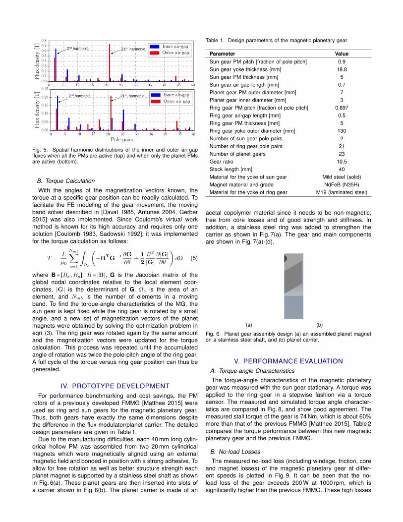
The purpose is to establish the near-optimum θi for the sub-sequent optimization routine. Since it is an unconstrained opti-mization problem, a gradient-based Broydon-Fletcher-Goldfarb-Shanno (BFGS) algorithm was used. Figure 4(a) compares theperformance of the implemented time-reduction techniques,which shows that the proposed techniques are more efficientthan the one without preconditioning, and a clear sign of conver-gence is evident after merely 2 iterations. Figure 4(b) displaysthe computed θi of each planet gear at the stall torque position.The worst net torque on a planet gear for these θi is found to be0.067 Nm. Figure 5 shows the spatial harmonic distributions ofthe inner and outer air-gap fluxes when all the PMs are activeand when only the planet PMs are active, respectively. The fluxmodulation effects of the planet PMs on the working harmonics(2nd order and 21st order) is evident.
Initial
Input
Magnetization
Vector Angles
Generate New
Set of
Magnetization
Vector Angles
Minimum
Magnetic Stored
Energy?
FE Model
Formation &
Conditioning
Field Solution
& Post
Processing
Output
Extraction
End
No
Yes
Fig. 3. Flow chart of the computation process.
0 2 4 6 8 10Number of Iterations
0
20
40
60
80
100
Perc
enta
ge E
rror
[%]
Precondition technique (i)Precondition technique (ii)Precondition technique (iii)Without Preconditioning
(a)
0 45 90 135 180 225 270 315 360Position angle θ [deg]
0
180
360
540
720
Mag
netiz
atio
nan
gle
θ i[d
eg]
θi
zsθ
(b)Fig. 4. (a) Convergence comparison between different time reductiontechniques; (b) Computed magnetization vector angle (θi) relative to itsrespective position angle (θ) at the stall torque position.
21st harmonic
2nd harmonic
2nd harmonic
21st harmonic
Fig. 5. Spatial harmonic distributions of the inner and outer air-gapfluxes when all the PMs are active (top) and when only the planet PMsare active (bottom).
B. Torque Calculation
With the angles of the magnetization vectors known, thetorque at a specific gear position can be readily calculated. Tofacilitate the FE modeling of the gear movement, the movingband solver described in [Davat 1985, Antunes 2004, Gerber2015] was also implemented. Since Coulomb’s virtual workmethod is known for its high accuracy and requires only onesolution [Coulomb 1983, Sadowski 1992], it was implementedfor the torque calculation as follows:
T =L
µ0
Nmb∑e=1
∫Ωe
(−BTG−1 ∂G
∂θ+
1
2
B2
|G|∂|G|∂θ
)dΩ (5)
where B = [Bx,By], B = |B|, G is the Jacobian matrix of theglobal nodal coordinates relative to the local element coor-dinates, |G| is the determinant of G, Ωe is the area of anelement, and Nmb is the number of elements in a movingband. To find the torque-angle characteristics of the MG, thesun gear is kept fixed while the ring gear is rotated by a smallangle, and a new set of magnetization vectors of the planetmagnets were obtained by solving the optimization problem ineqn. (3). The ring gear was rotated again by the same amountand the magnetization vectors were updated for the torquecalculation. This process was repeated until the accumulatedangle of rotation was twice the pole-pitch angle of the ring gear.A full cycle of the torque versus ring gear position can thus begenerated.
IV. PROTOTYPE DEVELOPMENTFor performance benchmarking and cost savings, the PM
rotors of a previously developed FMMG [Matthee 2015] wereused as ring and sun gears for the magnetic planetary gear.Thus, both gears have exactly the same dimensions despitethe difference in the flux modulator/planet carrier. The detaileddesign parameters are given in Table 1.
Due to the manufacturing difficulties, each 40 mm long cylin-drical hollow PM was assembled from two 20 mm cylindricalmagnets which were magnetically aligned using an externalmagnetic field and bonded in position with a strong adhesive. Toallow for free rotation as well as better structure strength eachplanet magnet is supported by a stainless steel shaft as shownin Fig. 6(a). These planet gears are then inserted into slots ofa carrier shown in Fig. 6(b). The planet carrier is made of an
Table 1. Design parameters of the magnetic planetary gear
Parameter ValueSun gear PM pitch [fraction of pole pitch] 0.9Sun gear yoke thickness [mm] 18.8Sun gear PM thickness [mm] 5Sun gear air-gap length [mm] 0.7Planet gear PM outer diameter [mm] 7Planet gear inner diameter [mm] 3Ring gear PM pitch [fraction of pole pitch] 0.897Ring gear air-gap length [mm] 0.5Ring gear PM thickness [mm] 5Ring gear yoke outer diameter [mm] 130Number of sun gear pole pairs 2Number of ring gear pole pairs 21Number of planet gears 23Gear ratio 10.5Stack length [mm] 40Material for the yoke of sun gear Mild steel (solid)Magnet material and grade NdFeB (N35H)Material for the yoke of ring gear M19 (laminated steel)
acetal copolymer material since it needs to be non-magnetic,free from core losses and of good strength and stiffness. Inaddition, a stainless steel ring was added to strengthen thecarrier as shown in Fig. 7(a). The gear and main componentsare shown in Fig. 7(a)-(d).
(a) (b)
Fig. 6. Planet gear assembly design (a) an assembled planet magneton a stainless steel shaft, and (b) planet carrier.
V. PERFORMANCE EVALUATIONA. Torque-angle Characteristics
The torque-angle characteristics of the magnetic planetarygear was measured with the sun gear stationary. A torque wasapplied to the ring gear in a stepwise fashion via a torquesensor. The measured and simulated torque angle character-istics are compared in Fig. 8, and show good agreement. Themeasured stall torque of the gear is 74 Nm, which is about 60%more than that of the previous FMMG [Matthee 2015]. Table 2compares the torque performance between this new magneticplanetary gear and the previous FMMG.
B. No-load Losses
The measured no-load loss (including windage, friction, coreand magnet losses) of the magnetic planetary gear at differ-ent speeds is plotted in Fig. 9. It can be seen that the no-load loss of the gear exceeds 200 W at 1000 rpm, which issignificantly higher than the previous FMMG. These high losses
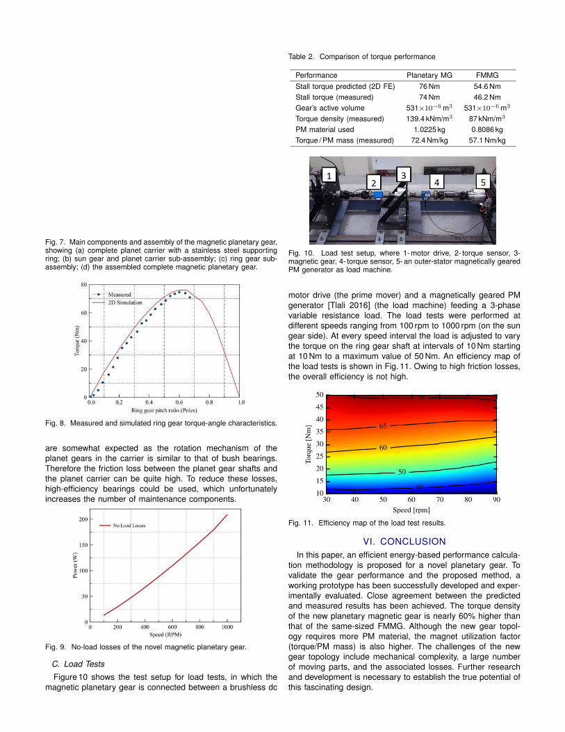
Fig. 7. Main components and assembly of the magnetic planetary gear,showing (a) complete planet carrier with a stainless steel supportingring; (b) sun gear and planet carrier sub-assembly; (c) ring gear sub-assembly; (d) the assembled complete magnetic planetary gear.
Fig. 8. Measured and simulated ring gear torque-angle characteristics.
are somewhat expected as the rotation mechanism of theplanet gears in the carrier is similar to that of bush bearings.Therefore the friction loss between the planet gear shafts andthe planet carrier can be quite high. To reduce these losses,high-efficiency bearings could be used, which unfortunatelyincreases the number of maintenance components.
Fig. 9. No-load losses of the novel magnetic planetary gear.
C. Load Tests
Figure 10 shows the test setup for load tests, in which themagnetic planetary gear is connected between a brushless dc
Table 2. Comparison of torque performance
Performance Planetary MG FMMGStall torque predicted (2D FE) 76 Nm 54.6 NmStall torque (measured) 74 Nm 46.2 NmGear’s active volume 531×10−6 m3 531×10−6 m3
Torque density (measured) 139.4 kNm/m3 87 kNm/m3
PM material used 1.0225 kg 0.8086 kgTorque / PM mass (measured) 72.4 Nm/kg 57.1 Nm/kg
Figure 8: Cross-section of the final modulator design
The stainless steel rings previously used to compress andmount the modulator are replaced by Vesconite plasticsupporting structures. Vesconite is a high load bearingplastic with dimensional stability but is also easy tomachine. It is therefore chosen as the ideal non-magneticmaterial to use for supporting the modulator. Themodulator inner support ring is mounted securely to thehigh-speed cover plate with 10 stainless steel bolts.
5. PERFORMANCE EVALUATION
In this section the experimental tests of the new magneticgear prototype is described. Results obtained in thesetests will be compared to those of the previously designedmagnetic gear. Fig. 9 is a photo of the test setup.
Figure 4.1: Full test-bench
The drive is controlled by a laptop which sends commands to the motor driver via USB.The torque sensors are both connected to and send realtime measurement data via USB. Itis important to note that the laptop charger should be disconnected to avoid noise errorswhile the torque sensors send data. The various shafts should be lined up as accurately aspossible to avoid vibration during high speed test conditions.
4.2 No-load TestThe no-load test is performed with nothing connected to the low-speed shaft of the gear.This test determines the losses present in the gear itself. The no-load setup is shown inFigure 4.2. As can be seen from this figure, only the drive is connected to the high-speedshaft of the gear via a prop-shaft and torque sensor while the low-speed shaft is floating.
Figure 4.2: No-load testbench
29
Figure 9: The test setup, where 1 - brushless DC motordrive, 2 - torque sensor, 3 - magnetic gear, 4 - torque sensor,5 - pseudo direct drive generator as load machine.
5.1 No-Load Test
This test determines the no-load loss (including windfriction and core losses) in the magnetic gear. As shownin Fig. 10, the no-load loss of the previous magnetic gearis 157 W at 1700 rpm while this loss reduces to only 49 Wat the same speed for the new gear design. This works outto be 68.7% reduction in losses at the mentioned speed. Itis evident that the new magnetic gear prototype has much
reduced no-load loss when compared with the previouslydesigned one.
Figure 10: Comparison of no-load loss between theprevious and the improved magnetic gears
5.2 Load Tests
The loss in a magnetic gear is mainly affected by itsoperation frequency and thus its rotational speed. The loadplaced on the gear has little effect on the losses of the gear.The load tests are performed at different speeds rangingfrom 100 rpm to 1700 rpm (on high speed side). At everyspeed interval the load is adjusted to vary the torque on thelow speed shaft at intervals of 10 Nm starting at 10 Nm to amaximum value of 40 Nm. Fig. 11 shows the output poweras a function of speed for different levels of output torque.The magnetic gear achieves a power output of 680 W at160 rpm and 40 Nm torque.
Figure 11: The output power of the magnetic gear as afunction of speeds for different loads (on low speed side)
The efficiency map of the magnetic gear at differentoperation conditions is given in Fig. 12. It can be observedthat the efficiency of the magnetic gear at 4 Nm and1500 rpm (high speed side) is about 95%. Comparing with
206
Fig. 10. Load test setup, where 1- motor drive, 2- torque sensor, 3-magnetic gear, 4- torque sensor, 5- an outer-stator magnetically gearedPM generator as load machine.
motor drive (the prime mover) and a magnetically geared PMgenerator [Tlali 2016] (the load machine) feeding a 3-phasevariable resistance load. The load tests were performed atdifferent speeds ranging from 100 rpm to 1000 rpm (on the sungear side). At every speed interval the load is adjusted to varythe torque on the ring gear shaft at intervals of 10 Nm startingat 10 Nm to a maximum value of 50 Nm. An efficiency map ofthe load tests is shown in Fig. 11. Owing to high friction losses,the overall efficiency is not high.
30 40 50 60 70 80 90Speed [rpm]
10
15
20
25
30
35
40
45
50
Torq
ue[N
m]
40
50
60
65
70
Fig. 11. Efficiency map of the load test results.
VI. CONCLUSIONIn this paper, an efficient energy-based performance calcula-
tion methodology is proposed for a novel planetary gear. Tovalidate the gear performance and the proposed method, aworking prototype has been successfully developed and exper-imentally evaluated. Close agreement between the predictedand measured results has been achieved. The torque densityof the new planetary magnetic gear is nearly 60% higher thanthat of the same-sized FMMG. Although the new gear topol-ogy requires more PM material, the magnet utilization factor(torque/PM mass) is also higher. The challenges of the newgear topology include mechanical complexity, a large numberof moving parts, and the associated losses. Further researchand development is necessary to establish the true potential ofthis fascinating design.

ACKNOWLEDGEMENTThis project was supported in part by a National Research
Foundation IFRR grant, the Tertiary Education Support Programof ESKOM, and SASOL Technology, all of South Africa. Theauthors would also like to acknowledge the contribution by MrJ Meeske, Mr P Petzer and Mr A Swart for the construction ofthe prototype.
REFERENCES
Antunes O, Bastos J, Sadowsk N (2004), “Using high-orderfinite elements in problems with movement,” IEEE T-MAG,40(2):529-532.
Atallah K, Howe D (2001), “A novel high-performance magneticgear,” IEEE T-MAG, 37(4):2844-2846.
Coulomb J (1983), “A methodology for the determination ofglobal electromechanical quantities from a finite elementanalysis and its application to the evaluation of magneticforces, torques and stiffness,” IEEE T-MAG, 19(6):2514-2519.
Davat B, Ren Z, Lajoie-Mazenc M (1985), “The movement infield modeling,” IEEE T-MAG, 21(6):2296-2298.
Davey K, et al. (2016), “Rotating cylinder planetary gear motor,”IEEE T-IA, (early access).
Gerber S, Wang RJ (2015), “Evaluation of movement facilitatingtechniques for finite element analysis of magnetically gearedelectrical machines,” IEEE T-MAG, 51(2):7400206.
Gouda E, Mezani S, Baghli L, Rezzoug A (2011), “Comparativestudy between mechanical and magnetic planetary gears,”IEEE T-MAG, 47(2):439-450.
Huang C, Tsai M, Dorrell D, Lin B (2008), “Development of amagnetic planetary gearbox,” IEEE T-MAG, 44(3):403-412.
Matthee A, Gerber S, Wang RJ (2015), “A high performanceconcentric magnetic gear,” Proc. of Southern African Univer-sities Power Engineering Conference, Johannesburg, SouthAfrica, pp.203-207.
Niguchi N, Hirata K (2012), “Transmission torque analysis ofa novel magnetic planetary gear employing 3-D FEM,” IEEET-MAG, 48(2):1043-1046.
Rens J, Atallah K, Calverley SD, Howe D (2007), “A novelmagnetic harmonic gear,” IEEE Int. Electric Machines DrivesConf. (IEMDC), 1:pp.698-703.
Sadowski N, Lefevre Y, Lajoie-Mazenc M, Cros J (1992), “Fi-nite element torque calculation in electrical machines whileconsidering the movement,” IEEE T-MAG, 28(2):1410-1413.
Tlali P, Gerber S, Wang RJ (2016), “Optimal design of an outer-stator magnetically geared permanent magnet machine,”IEEE T-MAG, 52(2):8100610.