warp processors - university of california, berkeley code morphing ... warp processors all that cad...
TRANSCRIPT
Warp Processors(a.k.a. Self-Improving Configurable IC Platforms)
Frank VahidDepartment of Computer Science and Engineering
University of California, RiversideFaculty member, Center for Embedded Computer Systems, UC Irvine
Ph.D. students: Roman Lysecky (grad. June 2004), Greg Stitt (grad. June 2005)UCR collaborators: Prof. Walid Najjar, Prof. Sheldon Tan
2
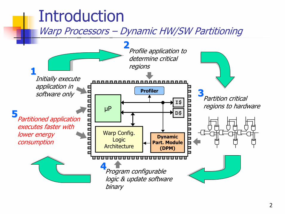
IntroductionWarp Processors – Dynamic HW/SW Partitioning
µPI$D$
Warp Config. Logic
Architecture
Profiler
Dynamic Part. Module
(DPM)
Partitioned application executes faster with lower energy consumption
55
Profile application to determine critical regions
22
Profiler
Initially execute application in software only
11
µPI$D$
Partition critical regions to hardware
33
Dynamic Part. Module
(DPM)
Program configurable logic & update software binary
44
Warp Config. Logic
Architecture
3
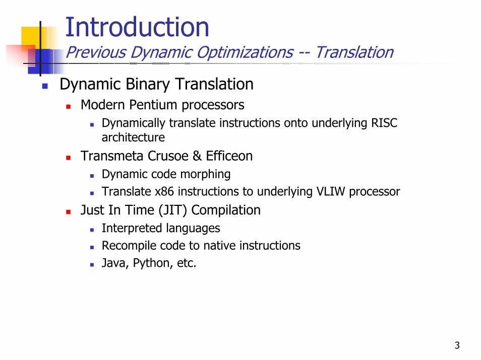
IntroductionPrevious Dynamic Optimizations -- Translation
Dynamic Binary TranslationModern Pentium processors
Dynamically translate instructions onto underlying RISC architecture
Transmeta Crusoe & Efficeon Dynamic code morphingTranslate x86 instructions to underlying VLIW processor
Just In Time (JIT) Compilation Interpreted languagesRecompile code to native instructionsJava, Python, etc.

4
IntroductionPrevious Dynamic Optimization -- Recompilation
Dynamic optimizations are increasingly commonDynamically recompile binary during executionDynamo [Bala, et al., 2000] - Dynamic software optimizations
Identify frequently executed code segments (hotpaths)Recompile with higher optimization
BOA [Gschwind, et al., 2000] - Dynamic optimizer for Power PC
AdvantagesTransparent optimizations
No designer effortNo tool restrictions
Adapts to actual usageSpeedups of up to 20%-30% -- 1.3X
5
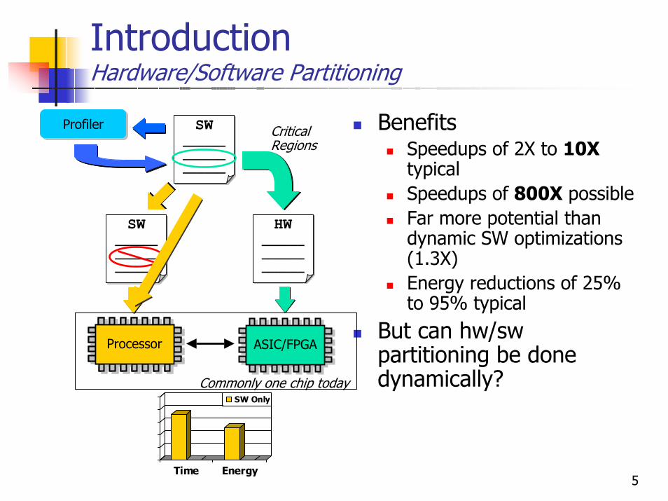
IntroductionHardware/Software Partitioning
SW__________________
SW__________________
SW__________________
HW__________________
SW__________________
SW__________________
ProcessorProcessor ProcessorASIC/FPGA
Critical Regions
ProfilerProfiler BenefitsSpeedups of 2X to 10XtypicalSpeedups of 800X possibleFar more potential than dynamic SW optimizations (1.3X)Energy reductions of 25% to 95% typical
But can hw/sw partitioning be done dynamically?
Time Energy
SW OnlyHW/SW
Time Energy
SW Only
ProcessorProcessor
Commonly one chip today
6
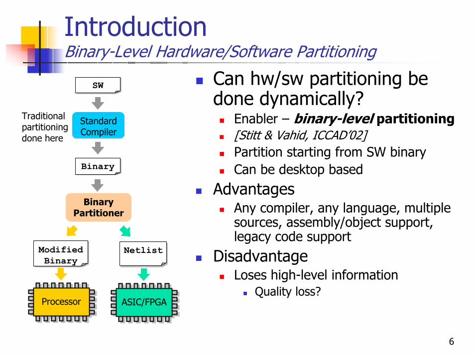
IntroductionBinary-Level Hardware/Software Partitioning
Can hw/sw partitioning be done dynamically?
Enabler – binary-level partitioning[Stitt & Vahid, ICCAD’02] Partition starting from SW binaryCan be desktop based
AdvantagesAny compiler, any language, multiple sources, assembly/object support, legacy code support
DisadvantageLoses high-level information
Quality loss?
BinarySW
ProfilingStandard Compiler
BinaryBinary
BinaryPartitioner
NetlistNetlistModified Binary
ProcessorProcessor ProcessorASIC/FPGA
Traditionalpartitioningdone here
7
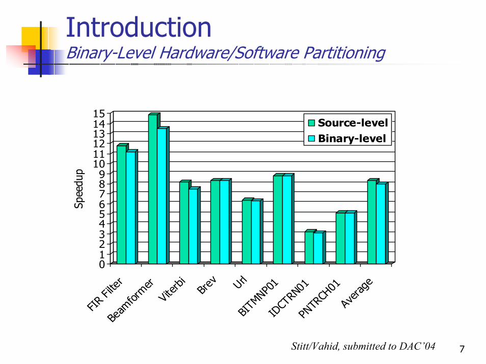
IntroductionBinary-Level Hardware/Software Partitioning
0123456789
101112131415
Spee
dup
FIR Fi
lter
Beam
former
Viterb
i
Brev Url
BITM
NP01
IDCT
RN01
PNTR
CH01
Avera
geSource-levelBinary-level
Stitt/Vahid, submitted to DAC’04
8
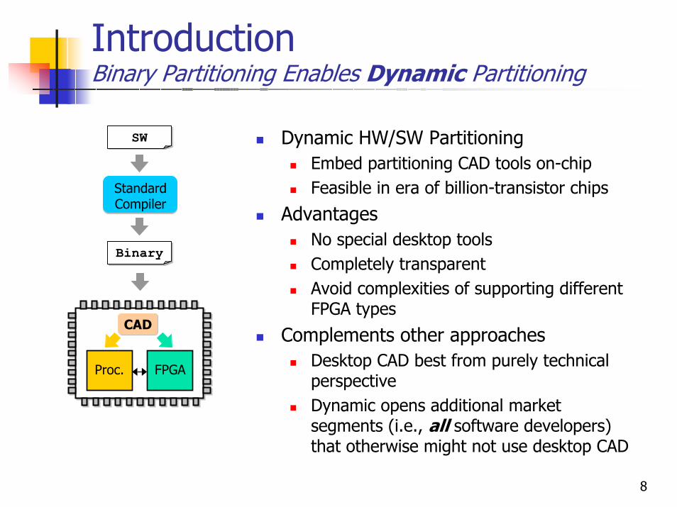
IntroductionBinary Partitioning Enables Dynamic Partitioning
Dynamic HW/SW PartitioningEmbed partitioning CAD tools on-chipFeasible in era of billion-transistor chips
AdvantagesNo special desktop toolsCompletely transparentAvoid complexities of supporting different FPGA types
Complements other approachesDesktop CAD best from purely technical perspectiveDynamic opens additional market segments (i.e., all software developers) that otherwise might not use desktop CAD
BinarySW
ProfilingStandard Compiler
BinaryBinary
CAD
FPGAProc.
9
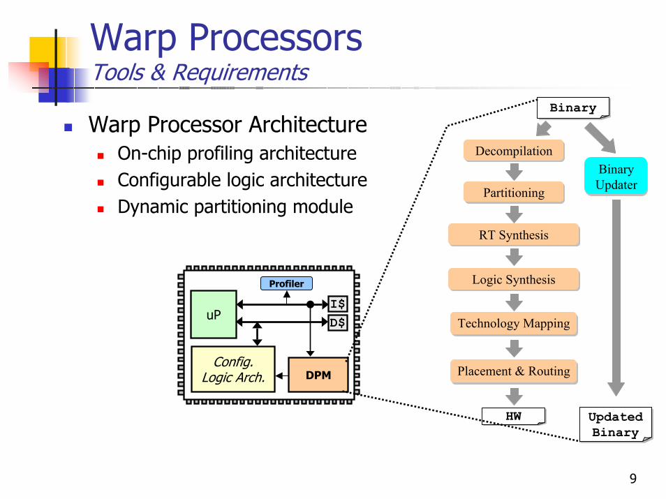
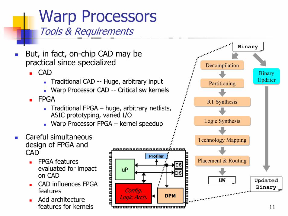
Warp ProcessorsTools & Requirements
uPI$D$
Config. Logic Arch.
Profiler
DPM
Warp Processor ArchitectureOn-chip profiling architectureConfigurable logic architectureDynamic partitioning module
BinaryBinary
Partitioning
BinaryHW
RT Synthesis
Technology Mapping
Placement & Routing
Logic Synthesis
DecompilationBinary Updater
BinaryUpdated Binary
10
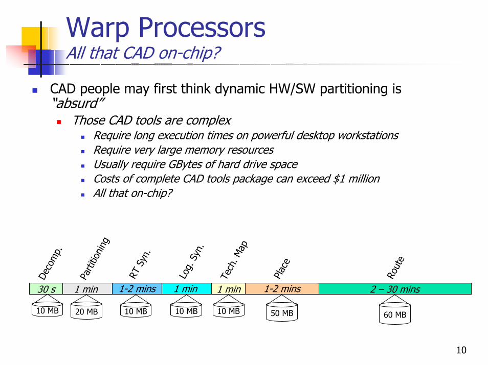
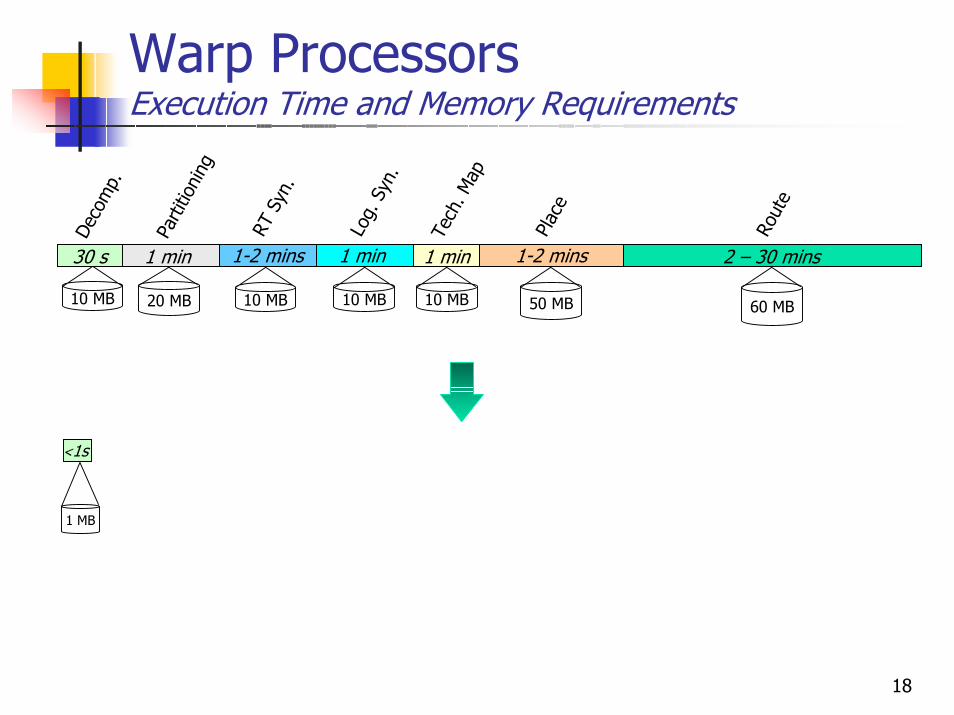
Warp ProcessorsAll that CAD on-chip?
CAD people may first think dynamic HW/SW partitioning is “absurd”
Those CAD tools are complexRequire long execution times on powerful desktop workstationsRequire very large memory resources Usually require GBytes of hard drive spaceCosts of complete CAD tools package can exceed $1 millionAll that on-chip?
50 MB 60 MB10 MB
1 min
Log.
Syn
.
1 min
Tech
. Map
1-2 mins Pl
ace
2 – 30 mins
Rout
e
1-2 mins
RT S
yn.
10 MB
30 s
Deco
mp.
1 min
Parti
tioni
ng
20 MB 10 MB 10 MB
11
Warp ProcessorsTools & Requirements
But, in fact, on-chip CAD may be practical since specialized
CAD Traditional CAD -- Huge, arbitrary inputWarp Processor CAD -- Critical sw kernels
FPGATraditional FPGA – huge, arbitrary netlists, ASIC prototyping, varied I/OWarp Processor FPGA – kernel speedup
uPI$D$
Config. Logic Arch.
Profiler
DPM
BinaryBinary
Partitioning
BinaryHW
RT Synthesis
Technology Mapping
Placement & Routing
Logic Synthesis
DecompilationBinary Updater
BinaryUpdated Binary
Careful simultaneous design of FPGA and CAD
FPGA features evaluated for impact on CADCAD influences FPGA featuresAdd architecture features for kernels
Config. Logic Arch.
12
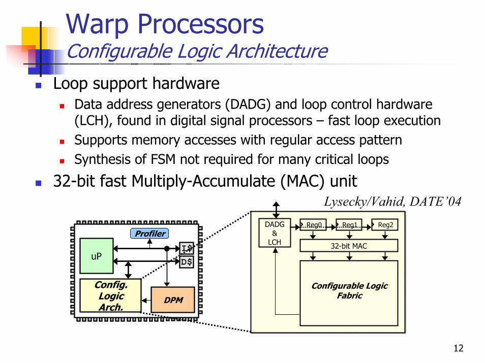
Warp ProcessorsConfigurable Logic Architecture
Loop support hardwareData address generators (DADG) and loop control hardware (LCH), found in digital signal processors – fast loop executionSupports memory accesses with regular access patternSynthesis of FSM not required for many critical loops
32-bit fast Multiply-Accumulate (MAC) unit
DADG &
LCH
Configurable Logic Fabric
Reg0
32-bit MAC
Reg1 Reg2
uPI$D$
Config. Logic Arch.
Profiler
DPM
Lysecky/Vahid, DATE’04
13
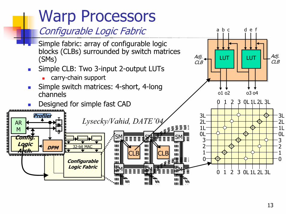
Warp ProcessorsConfigurable Logic Fabric
DADGLCH
Configurable Logic Fabric
32-bit MAC
SM
CLB
SM
SM
SM
SM
SM
CLB
SM
CLB
SM
SM
SM
SM
SM
CLB
Simple fabric: array of configurable logic blocks (CLBs) surrounded by switch matrices (SMs)Simple CLB: Two 3-input 2-output LUTs
carry-chain supportSimple switch matrices: 4-short, 4-long channelsDesigned for simple fast CAD
Lysecky/Vahid, DATE’04ARM
I$D$
Config. Logic Arch.
Profiler
DPM
LUTLUT
a b c d e f
o1 o2 o3 o4
Adj.CLB
Adj.CLB
0
0L
1
1L2L
2
3L
3
0123
0L1L2L3L
0123
0L 1L 2L 3L
0 1 2 3 0L 1L 2L 3L
14
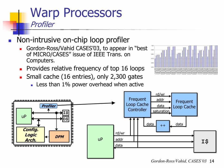
Warp ProcessorsProfiler
Non-intrusive on-chip loop profiler Gordon-Ross/Vahid CASES’03, to appear in “best of MICRO/CASES” issue of IEEE Trans. on Computers.Provides relative frequency of top 16 loopsSmall cache (16 entries), only 2,300 gates
Less than 1% power overhead when active
0.50
0.60
0.70
0.80
0.90
1.00
1-wa
y 16
x81-
way
16x1
21-
way
16x1
61-
way
16x2
41-
way
16x3
22-
way
16x8
2-wa
y 16
x12
2-wa
y 16
x16
2-wa
y 16
x24
2-wa
y 16
x32
4-wa
y 16
x84-
way
16x1
24-
way
16x1
64-
way
16x2
44-
way
16x3
28-
way
16x8
8-wa
y 16
x12
8-wa
y 16
x16
8-wa
y 16
x24
8-wa
y 16
x32
1-wa
y 32
x81-
way
32x1
21-
way
32x1
61-
way
32x2
41-
way
32x3
22-
way
32x8
2-wa
y 32
x12
2-wa
y 32
x16
2-wa
y 32
x24
2-wa
y 32
x32
4-wa
y 32
x84-
way
32x1
24-
way
32x1
64-
way
32x2
44-
way
32x3
28-
way
32x8
8-wa
y 32
x12
8-wa
y 32
x16
8-wa
y 32
x24
8-wa
y 32
x32
1-wa
y 64
x81-
way
64x1
21-
way
64x1
61-
way
64x2
41-
way
64x3
22-
way
64x8
2-wa
y 64
x12
2-wa
y 64
x16
2-wa
y 64
x24
2-wa
y 64
x32
4-wa
y 64
x84-
way
64x1
24-
way
64x1
64-
way
64x2
44-
way
64x3
28-
way
64x8
8-wa
y 64
x12
8-wa
y 64
x16
8-wa
y 64
x24
8-wa
y 64
x32
Frequent Loop Cache Controller
Frequent Loop Cache
++
I$MIPS/ARMuP
Frequent Loop Cache
Frequent Loop Cache Controller
++
rd/wraddr
datadata
rd/wr
addr
datasaturation
I$data
Gordon-Ross/Vahid, CASES’03
uPI$D$
Config. Logic Arch.
Profiler
DPM
15
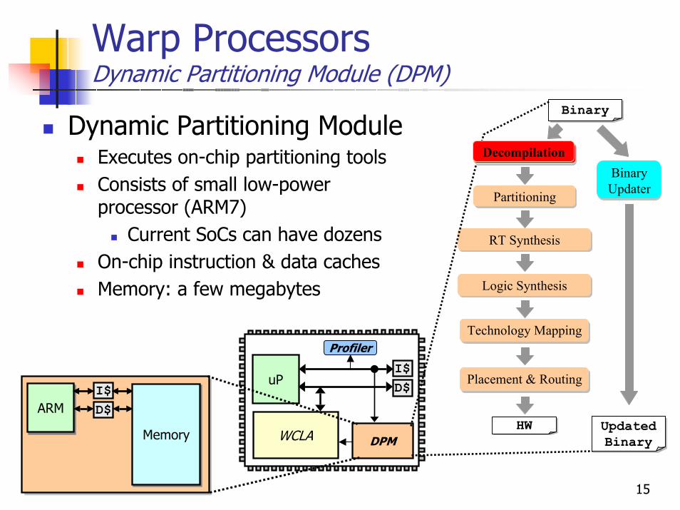
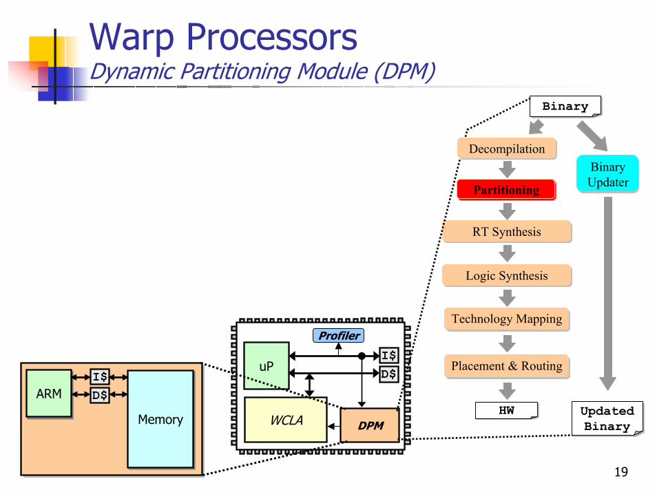
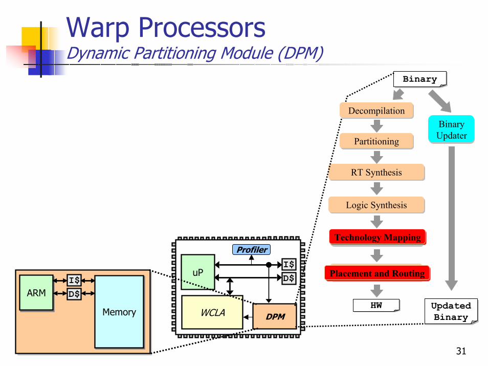
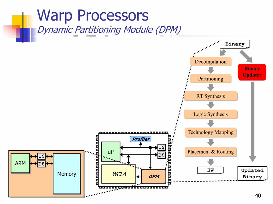
Warp ProcessorsDynamic Partitioning Module (DPM)
Dynamic Partitioning ModuleExecutes on-chip partitioning toolsConsists of small low-power processor (ARM7)
Current SoCs can have dozensOn-chip instruction & data cachesMemory: a few megabytes
uPI$D$
WCLA
Profiler
DPM
ARMARMI$D$
MemoryMemory
BinaryBinary
Partitioning
BinaryHW
RT Synthesis
Technology Mapping
Placement & Routing
Logic Synthesis
DecompilationBinary Updater
BinaryUpdated Binary
Decompilation
16
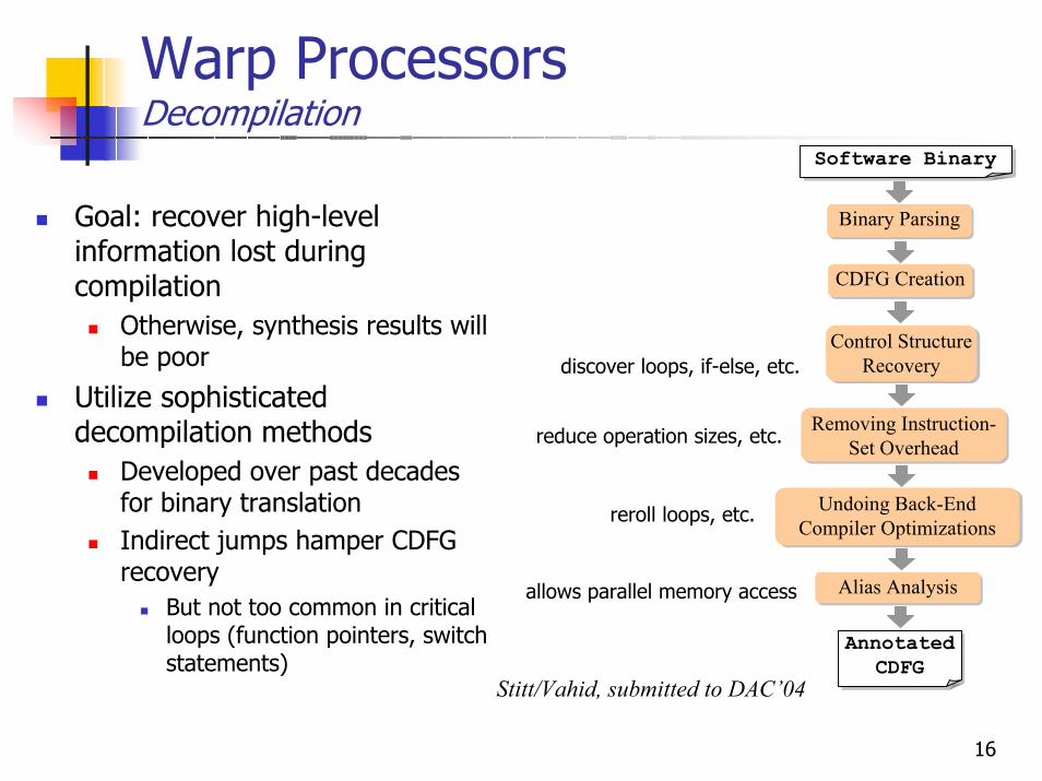
Warp ProcessorsDecompilation
CDFG Creation
Binary Parsing
Software Binary
Binary Parsing
Software Binary
CDFG Creation
Goal: recover high-level information lost during compilation
Otherwise, synthesis results will be poor
Utilize sophisticated decompilation methods
Developed over past decades for binary translationIndirect jumps hamper CDFG recovery
But not too common in critical loops (function pointers, switch statements)
Annotated CDFG
Alias Analysis
Undoing Back-End Compiler Optimizations
Removing Instruction-Set Overhead
Control Structure Recovery
Control Structure Recovery
Undoing Back-End Compiler Optimizations
Alias Analysis
Annotated CDFG
Removing Instruction-Set Overhead
discover loops, if-else, etc.
reduce operation sizes, etc.
reroll loops, etc.
allows parallel memory access
Stitt/Vahid, submitted to DAC’04
17
Warp ProcessorsDecompilation Results
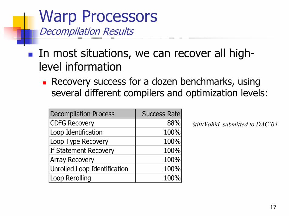
In most situations, we can recover all high-level information
Recovery success for a dozen benchmarks, using several different compilers and optimization levels:
Decompilation Process Success RateCDFG Recovery 88%Loop Identification 100%Loop Type Recovery 100%If Statement Recovery 100%Array Recovery 100%Unrolled Loop Identification 100%Loop Rerolling 100%
Stitt/Vahid, submitted to DAC’04
18
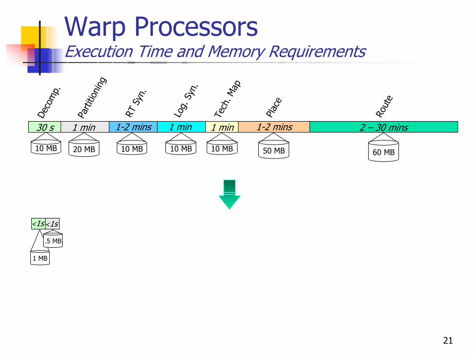
Warp ProcessorsExecution Time and Memory Requirements
<1s
1 MB
50 MB 60 MB10 MB
1 min
Log.
Syn
.
1 min
Tech
. Map
1-2 mins
Plac
e
2 – 30 mins
Rout
e
1-2 minsRT
Syn
.10 MB
30 s
Deco
mp.
1 min
Parti
tioni
ng
20 MB 10 MB 10 MB
19
Warp ProcessorsDynamic Partitioning Module (DPM)
uPI$D$
WCLA
Profiler
DPM
ARMARMI$D$
MemoryMemory
BinaryBinary
Partitioning
BinaryHW
RT Synthesis
Technology Mapping
Placement & Routing
Logic Synthesis
DecompilationBinary Updater
BinaryUpdated Binary
Partitioning
20
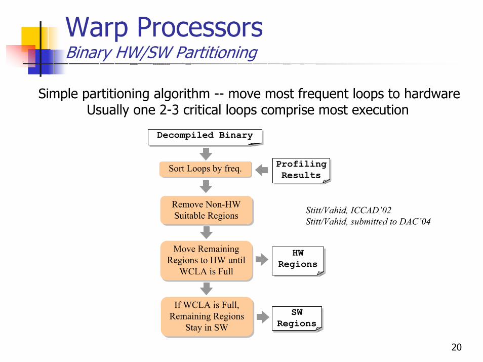
Warp ProcessorsBinary HW/SW Partitioning
Simple partitioning algorithm -- move most frequent loops to hardwareUsually one 2-3 critical loops comprise most execution
Decompiled BinaryDecompiled Binary
Profiling Results
Profiling ResultsSort Loops by freq.
Remove Non-Hw Suitable Regions
Remove Non-HW Suitable Regions Stitt/Vahid, ICCAD’02
Stitt/Vahid, submitted to DAC’04
Move Remaining Regions to HW until
WCLA is Full
Move Remaining Regions to HW until
WCLA is Full
HW Regions
HW Regions
If WCLA is Full, Remaining Regions
Stay in SW
If WCLA is Full, Remaining Regions
Stay in SWSw
RegionsSW
Regions
21
Warp ProcessorsExecution Time and Memory Requirements
<1s
1 MB
<1s
.5 MB
50 MB 60 MB10 MB
1 min
Log.
Syn
.
1 min
Tech
. Map
1-2 mins
Plac
e
2 – 30 mins
Rout
e
1-2 minsRT
Syn
.10 MB
30 s
Deco
mp.
1 min
Parti
tioni
ng
20 MB 10 MB 10 MB
22
Warp ProcessorsDynamic Partitioning Module (DPM)
uPI$D$
WCLA
Profiler
DPM
ARMARMI$D$
MemoryMemory
BinaryBinary
Partitioning
BinaryHW
RT Synthesis
Technology Mapping
Placement & Routing
Logic Synthesis
DecompilationBinary Updater
BinaryUpdated Binary
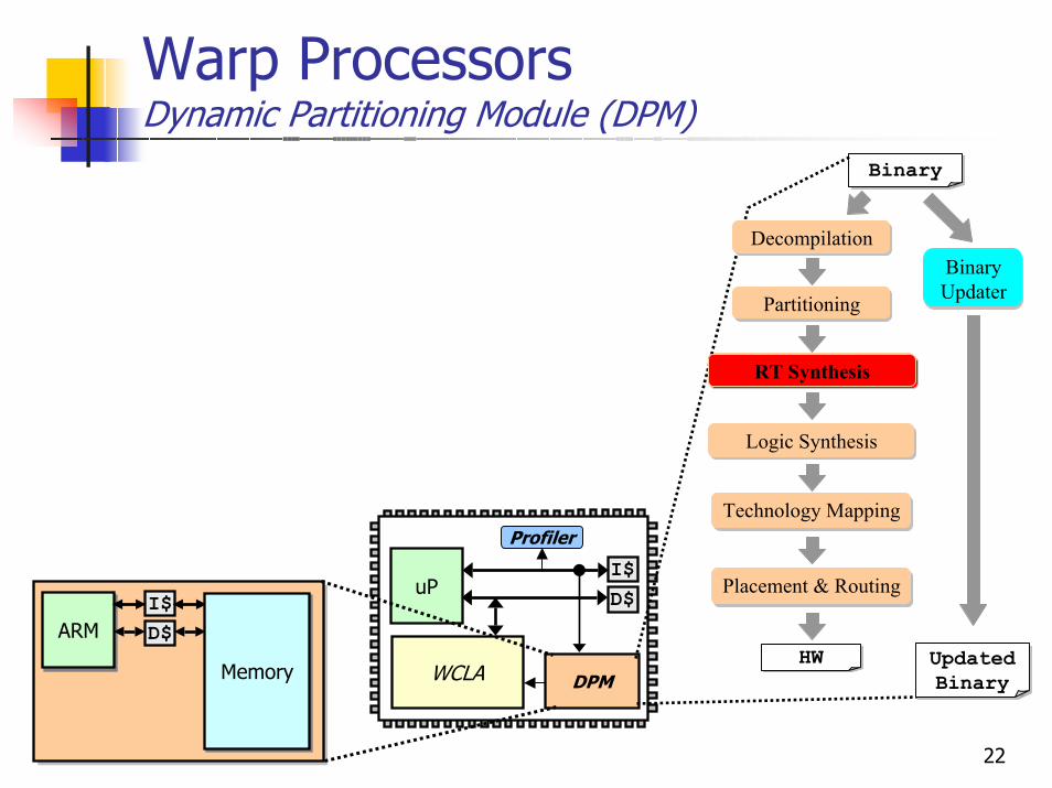
RT Synthesis

23
Warp ProcessorsRT Synthesis
Converts decompiled CDFG to Boolean expressionsMaps memory accesses to our data address generator architecture
Detects read/write, memory access pattern, memory read/write ordering
Optimizes dataflow graphRemoves address calculations and loop counter/exit conditionsLoop control handled by Loop Control Hardware
1 r1
+ Read
r1 +
r2
• Memory Read
• Increment Address
r3
DADG Read
+
r2
r3
Stitt/Lysecky/Vahid, DAC’03
24
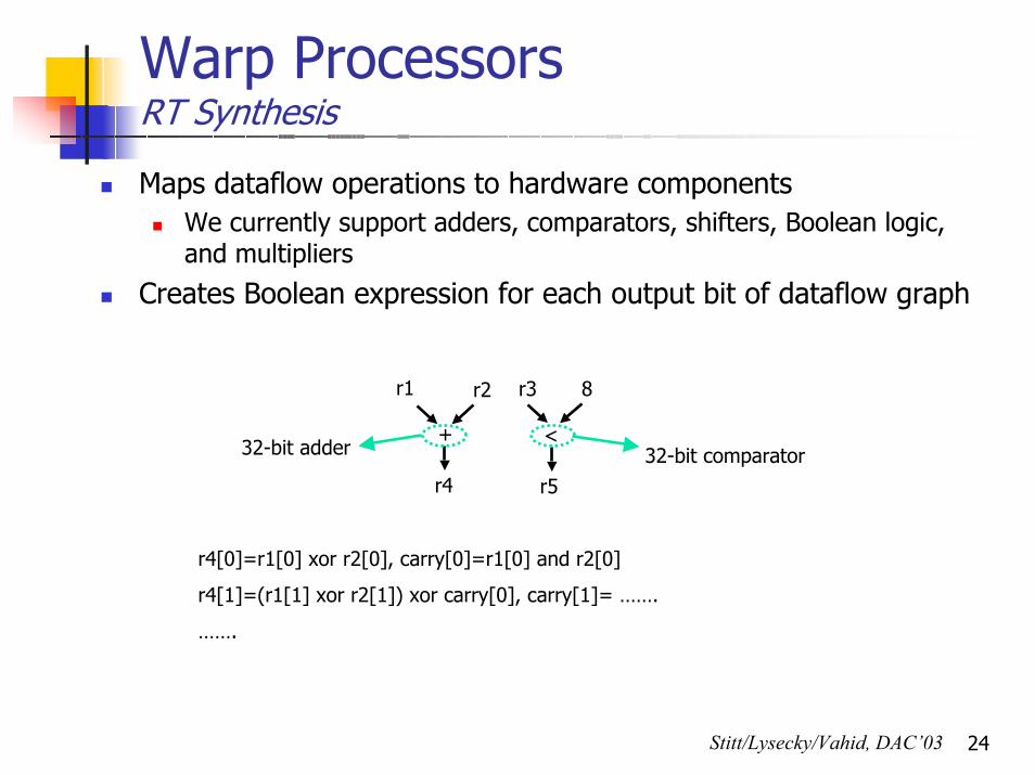
Warp ProcessorsRT Synthesis
Maps dataflow operations to hardware componentsWe currently support adders, comparators, shifters, Boolean logic, and multipliers
Creates Boolean expression for each output bit of dataflow graph
r1 r2
+
r4
r3 8
<
r5
32-bit adder 32-bit comparator
r4[0]=r1[0] xor r2[0], carry[0]=r1[0] and r2[0]
r4[1]=(r1[1] xor r2[1]) xor carry[0], carry[1]= …….
…….
Stitt/Lysecky/Vahid, DAC’03
25
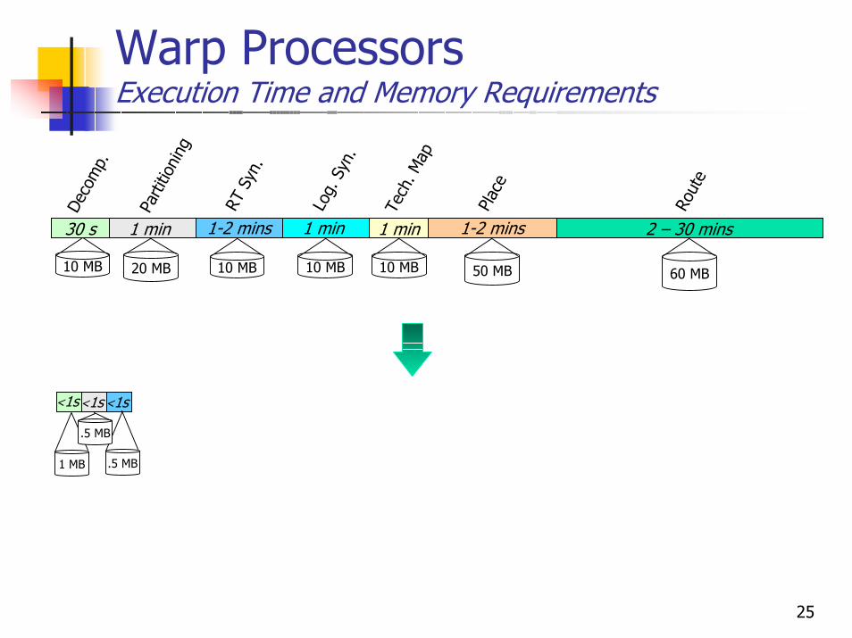
Warp ProcessorsExecution Time and Memory Requirements
<1s
.5 MB
<1s
1 MB
<1s
.5 MB
50 MB 60 MB10 MB
1 min
Log.
Syn
.
1 min
Tech
. Map
1-2 mins
Plac
e
2 – 30 mins
Rout
e
1-2 minsRT
Syn
.10 MB
30 s
Deco
mp.
1 min
Parti
tioni
ng
20 MB 10 MB 10 MB
26
Warp ProcessorsDynamic Partitioning Module (DPM)
uPI$D$
WCLA
Profiler
DPM
ARMARMI$D$
MemoryMemory
BinaryBinary
Partitioning
BinaryHW
RT Synthesis
Technology Mapping
Placement & Routing
Logic Synthesis
DecompilationBinary Updater
BinaryUpdated Binary
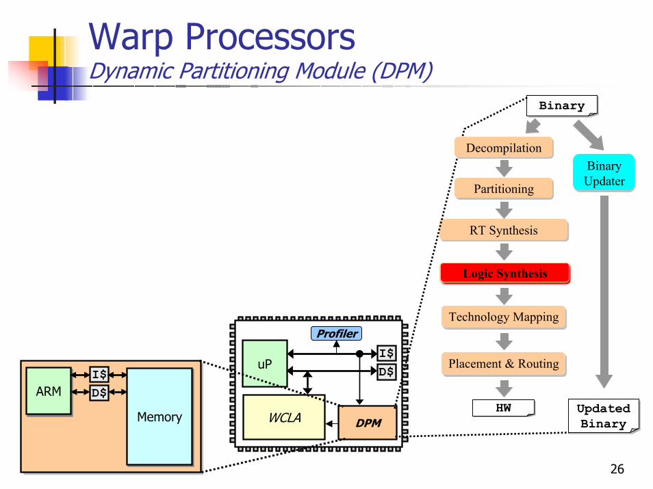
Logic Synthesis
27
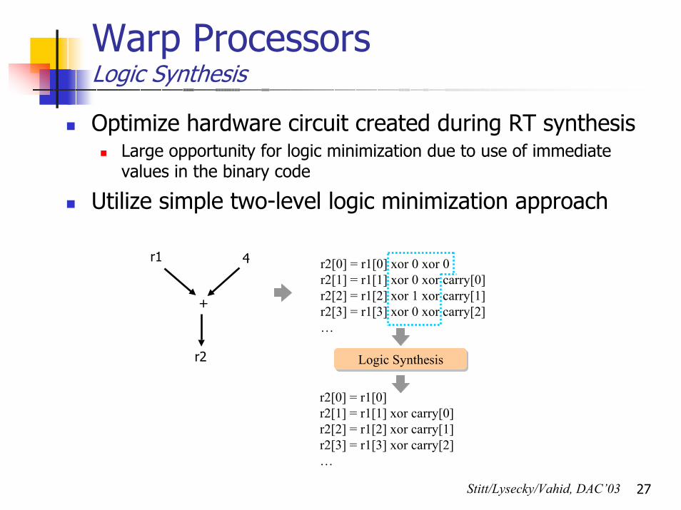
Warp ProcessorsLogic Synthesis
Optimize hardware circuit created during RT synthesisLarge opportunity for logic minimization due to use of immediatevalues in the binary code
Utilize simple two-level logic minimization approach
r2[0] = r1[0]r2[1] = r1[1] xor carry[0]r2[2] = r1[2] xor carry[1]r2[3] = r1[3] xor carry[2]…
Logic Synthesis
r2[0] = r1[0] xor 0 xor 0r2[1] = r1[1] xor 0 xor carry[0]r2[2] = r1[2] xor 1 xor carry[1]r2[3] = r1[3] xor 0 xor carry[2]…
r1 4
+
r2
Stitt/Lysecky/Vahid, DAC’03
28
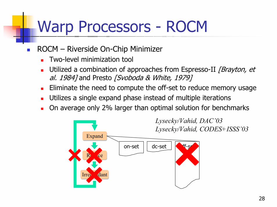
Warp Processors - ROCMROCM – Riverside On-Chip Minimizer
Two-level minimization toolUtilized a combination of approaches from Espresso-II [Brayton, et al. 1984] and Presto [Svoboda & White, 1979]Eliminate the need to compute the off-set to reduce memory usageUtilizes a single expand phase instead of multiple iterationsOn average only 2% larger than optimal solution for benchmarks
Expand
Reduce
Irredundant
dc-seton-set off-set
Lysecky/Vahid, DAC’03Lysecky/Vahid, CODES+ISSS’03
29
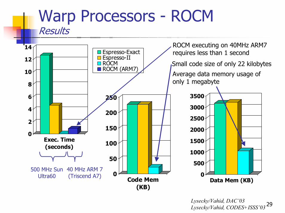
Warp Processors - ROCMResults
0
2
4
6
8
10
12
14
Exec. Time(seconds)
Espresso-ExactEspresso-IIROCMROCM (ARM7)
40 MHz ARM 7(Triscend A7) 0
50
100
150
200
250
Code Mem(KB)
0
500
1000
1500
2000
2500
3000
3500
Data Mem (KB)
ROCM executing on 40MHz ARM7 requires less than 1 second
Small code size of only 22 kilobytes
Average data memory usage of only 1 megabyte
Lysecky/Vahid, DAC’03Lysecky/Vahid, CODES+ISSS’03
500 MHz Sun Ultra60
30
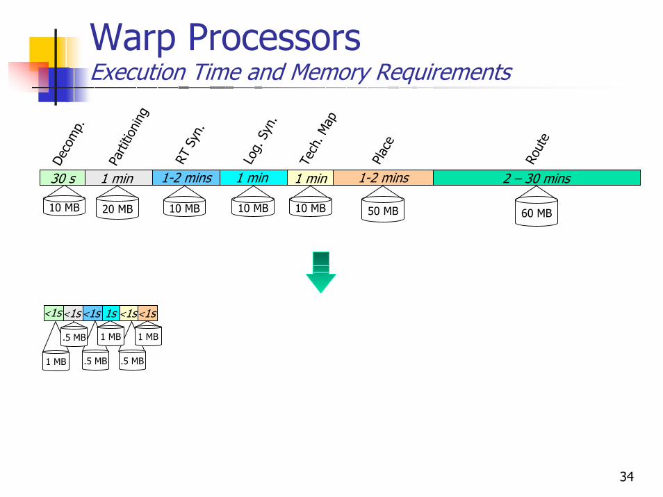
Warp ProcessorsExecution Time and Memory Requirements
<1s
.5 MB
1s
1 MB
<1s
1 MB
<1s
.5 MB
50 MB 60 MB10 MB
1 min
Log.
Syn
.
1 min
Tech
. Map
1-2 mins
Plac
e
2 – 30 mins
Rout
e
1-2 minsRT
Syn
.10 MB
30 s
Deco
mp.
1 min
Parti
tioni
ng
20 MB 10 MB 10 MB
31
Warp ProcessorsDynamic Partitioning Module (DPM)
uPI$D$
WCLA
Profiler
DPM
ARMARMI$D$
MemoryMemory
BinaryBinary
Partitioning
BinaryHW
RT Synthesis
Technology Mapping
Placement & Routing
Logic Synthesis
DecompilationBinary Updater
BinaryUpdated Binary
Technology Mapping
Placement and Routing
32
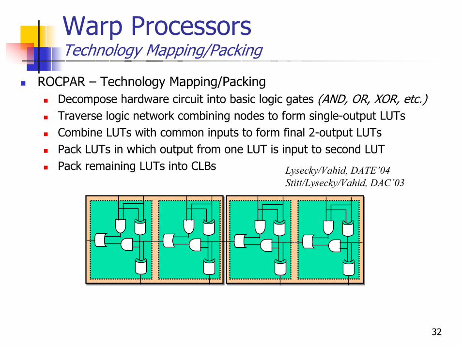
Warp ProcessorsTechnology Mapping/Packing
ROCPAR – Technology Mapping/PackingDecompose hardware circuit into basic logic gates (AND, OR, XOR, etc.)Traverse logic network combining nodes to form single-output LUTsCombine LUTs with common inputs to form final 2-output LUTsPack LUTs in which output from one LUT is input to second LUTPack remaining LUTs into CLBs Lysecky/Vahid, DATE’04
Stitt/Lysecky/Vahid, DAC’03
33
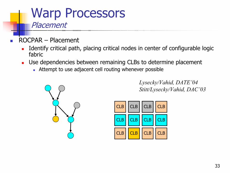
Warp ProcessorsPlacement
ROCPAR – PlacementIdentify critical path, placing critical nodes in center of configurable logic fabricUse dependencies between remaining CLBs to determine placement
Attempt to use adjacent cell routing whenever possible
CLB CLB CLB CLB
CLB CLB CLB CLB
CLB CLB CLB CLB
CLB CLB CLB CLB
CLB CLB
CLB
Lysecky/Vahid, DATE’04Stitt/Lysecky/Vahid, DAC’03
34
Warp ProcessorsExecution Time and Memory Requirements
<1s
.5 MB
<1s
.5 MB
1s
1 MB
<1s
1 MB
<1s
1 MB
<1s
.5 MB
50 MB 60 MB10 MB
1 min
Log.
Syn
.
1 min
Tech
. Map
1-2 mins
Plac
e
2 – 30 mins
Rout
e
1-2 minsRT
Syn
.10 MB
30 s
Deco
mp.
1 min
Parti
tioni
ng
20 MB 10 MB 10 MB
35
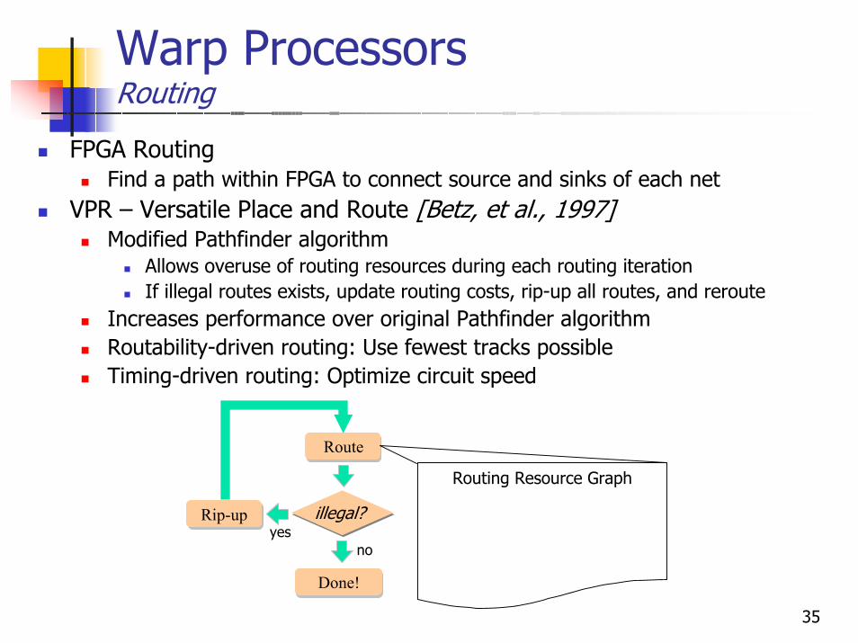
Warp ProcessorsRouting
FPGA RoutingFind a path within FPGA to connect source and sinks of each net
VPR – Versatile Place and Route [Betz, et al., 1997]Modified Pathfinder algorithm
Allows overuse of routing resources during each routing iterationIf illegal routes exists, update routing costs, rip-up all routes, and reroute
Increases performance over original Pathfinder algorithmRoutability-driven routing: Use fewest tracks possibleTiming-driven routing: Optimize circuit speed
Route
Rip-up
Done!
congestion?illegal?
noyes
Routing Resource Graph
36
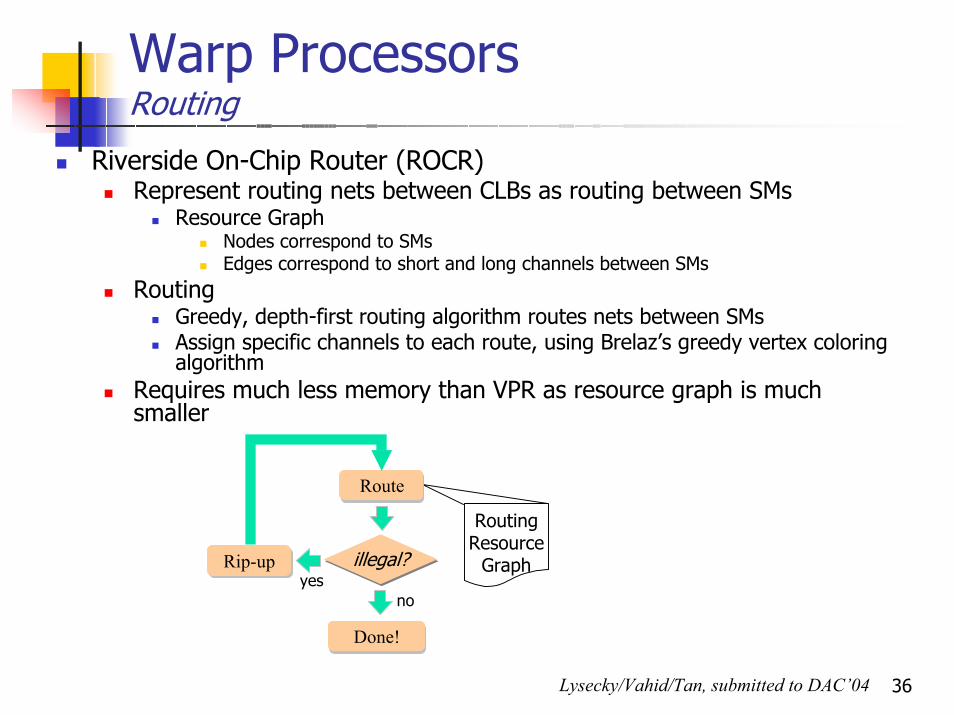
Warp Processors Routing
Riverside On-Chip Router (ROCR)Represent routing nets between CLBs as routing between SMs
Resource GraphNodes correspond to SMsEdges correspond to short and long channels between SMs
RoutingGreedy, depth-first routing algorithm routes nets between SMsAssign specific channels to each route, using Brelaz’s greedy vertex coloring algorithm
Requires much less memory than VPR as resource graph is much smaller
Routing Resource GraphRouting Resource
Graph
Route
Rip-up
Done!
congestion?illegal?
noyes
Lysecky/Vahid/Tan, submitted to DAC’04
37
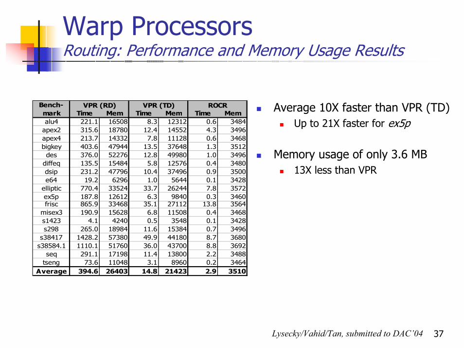
Warp Processors Routing: Performance and Memory Usage Results
Time Mem Time Mem Time Memalu4 221.1 16508 8.3 12312 0.6 3484
apex2 315.6 18780 12.4 14552 4.3 3496apex4 213.7 14332 7.8 11128 0.6 3468bigkey 403.6 47944 13.5 37648 1.3 3512des 376.0 52276 12.8 49980 1.0 3496
diffeq 135.5 15484 5.8 12576 0.4 3480dsip 231.2 47796 10.4 37496 0.9 3500e64 19.2 6296 1.0 5644 0.1 3428
elliptic 770.4 33524 33.7 26244 7.8 3572ex5p 187.8 12612 6.3 9840 0.3 3460frisc 865.9 33468 35.1 27112 13.8 3564
misex3 190.9 15628 6.8 11508 0.4 3468s1423 4.1 4240 0.5 3548 0.1 3428s298 265.0 18984 11.6 15384 0.7 3496
s38417 1428.2 57380 49.9 44180 8.7 3680s38584.1 1110.1 51760 36.0 43700 8.8 3692
seq 291.1 17198 11.4 13800 2.2 3488tseng 73.6 11048 3.1 8960 0.2 3464
Average 394.6 26403 14.8 21423 2.9 3510
VPR (TD) ROCRBench-mark
VPR (RD) Average 10X faster than VPR (TD)Up to 21X faster for ex5p
Memory usage of only 3.6 MB13X less than VPR
Lysecky/Vahid/Tan, submitted to DAC’04
38
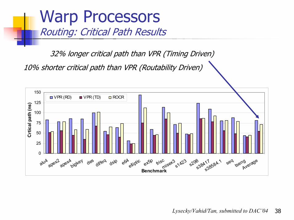
Warp ProcessorsRouting: Critical Path Results
32% longer critical path than VPR (Timing Driven)
0
25
50
75
100
125
150
alu4apex2
apex4bigkey des
diffeq
dsip e64elliptic ex5p fris
cmisex3
s1423s298
s38417
s38584.1 seqtseng
Average
Benchmark
Crt
ical
pat
h (n
s)
VPR (RD) VPR (TD) ROCR
10% shorter critical path than VPR (Routability Driven)
Lysecky/Vahid/Tan, submitted to DAC’04
39
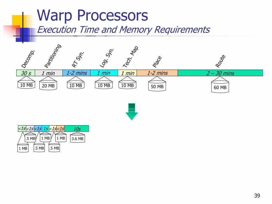
Warp ProcessorsExecution Time and Memory Requirements
<1s
.5 MB
<1s
.5 MB
1s
1 MB
<1s
1 MB
10s
3.6 MB
<1s
1 MB
<1s
.5 MB
50 MB 60 MB10 MB
1 min
Log.
Syn
.
1 min
Tech
. Map
1-2 mins
Plac
e
2 – 30 mins
Rout
e
1-2 minsRT
Syn
.10 MB
30 s
Deco
mp.
1 min
Parti
tioni
ng
20 MB 10 MB 10 MB
40
Warp ProcessorsDynamic Partitioning Module (DPM)
uPI$D$
WCLA
Profiler
DPM
ARMARMI$D$
MemoryMemory
BinaryBinary
Partitioning
BinaryHW
RT Synthesis
Technology Mapping
Placement & Routing
Logic Synthesis
DecompilationBinary Updater
BinaryUpdated Binary
Binary Updater
41
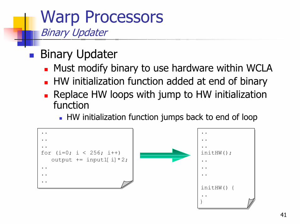
Warp ProcessorsBinary Updater
Binary UpdaterMust modify binary to use hardware within WCLAHW initialization function added at end of binaryReplace HW loops with jump to HW initialization function
HW initialization function jumps back to end of loop
..
..
..for (i=0; i < 256; i++)
output += input1[i]*2;......
..
..
..for (i=0; i < 256; i++)
output += input1[i]*2;......
..
..
..initHw();enableLoop = 1;......
..
..
..initHW();......
initHW() {..}
42
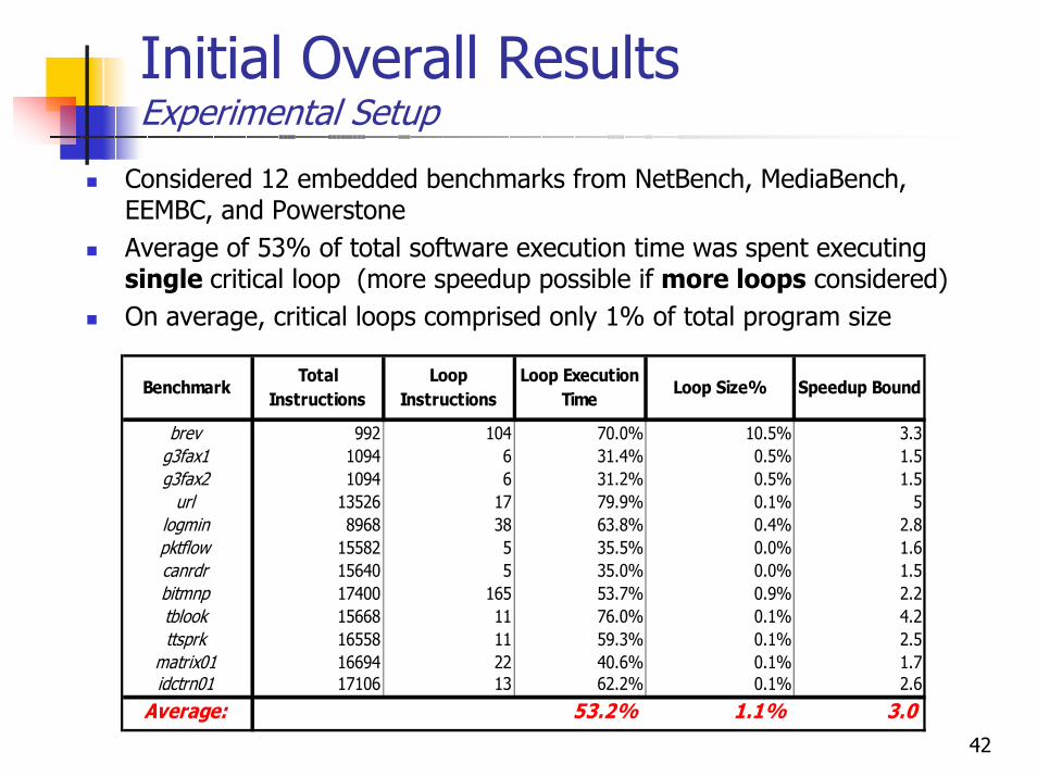
Initial Overall Results Experimental Setup
Considered 12 embedded benchmarks from NetBench, MediaBench, EEMBC, and PowerstoneAverage of 53% of total software execution time was spent executing single critical loop (more speedup possible if more loops considered)On average, critical loops comprised only 1% of total program size
brev 992 104 70.0% 10.5% 3.3g3fax1 1094 6 31.4% 0.5% 1.5g3fax2 1094 6 31.2% 0.5% 1.5
url 13526 17 79.9% 0.1% 5logmin 8968 38 63.8% 0.4% 2.8pktflow 15582 5 35.5% 0.0% 1.6canrdr 15640 5 35.0% 0.0% 1.5bitmnp 17400 165 53.7% 0.9% 2.2tblook 15668 11 76.0% 0.1% 4.2ttsprk 16558 11 59.3% 0.1% 2.5
matrix01 16694 22 40.6% 0.1% 1.7idctrn01 17106 13 62.2% 0.1% 2.6
Average: 53.2% 1.1% 3.0
Speedup BoundLoop
InstructionsBenchmark
Total Instructions
Loop Execution Time
Loop Size%
43
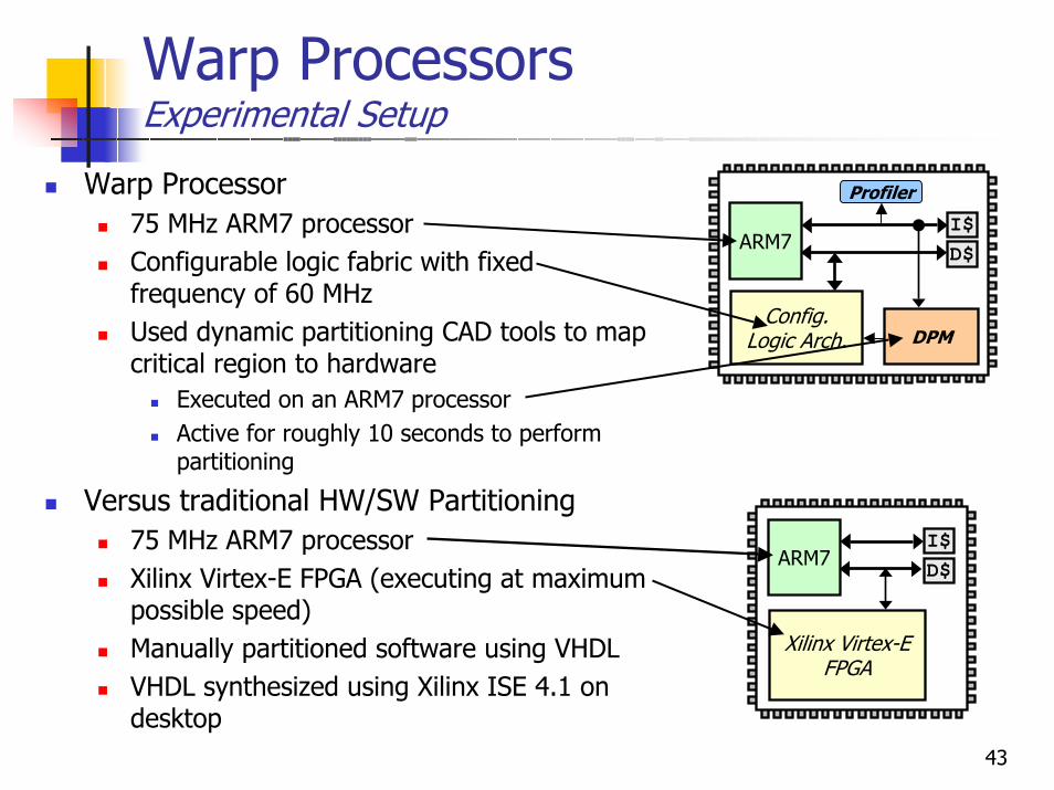
Warp ProcessorsExperimental Setup
Warp Processor75 MHz ARM7 processorConfigurable logic fabric with fixed frequency of 60 MHzUsed dynamic partitioning CAD tools to map critical region to hardware
Executed on an ARM7 processorActive for roughly 10 seconds to perform partitioning
Versus traditional HW/SW Partitioning75 MHz ARM7 processorXilinx Virtex-E FPGA (executing at maximum possible speed)Manually partitioned software using VHDLVHDL synthesized using Xilinx ISE 4.1 on desktop
ARM7I$D$
Config. Logic Arch.
Profiler
DPM
ARM7I$D$
Xilinx Virtex-E FPGA
44
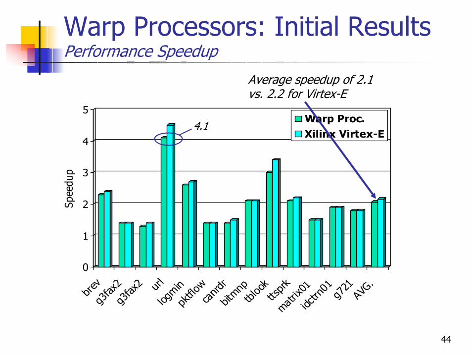
Warp Processors: Initial ResultsPerformance Speedup
0
1
2
3
4
5
Spee
dup
brev
g3fax
2g3
fax2 url
logmin
pktflo
wca
nrdr
bitmnptbl
ook
ttsprk
matrix0
1idc
trn01
g721
AVG.
Warp Proc.Xilinx Virtex-E
Average speedup of 2.1vs. 2.2 for Virtex-E
4.1
45
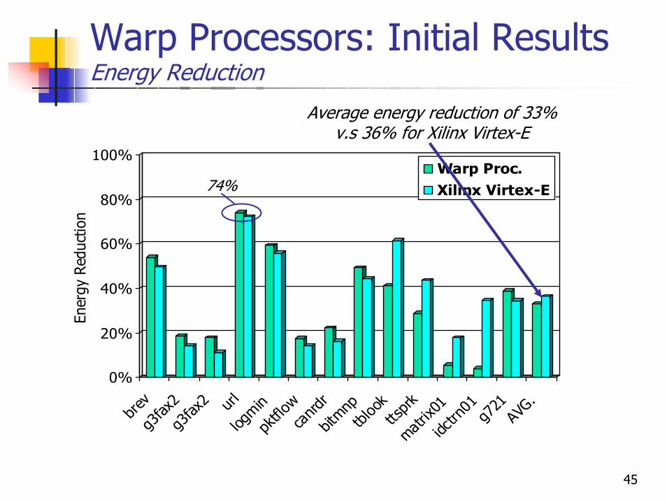
Warp Processors: Initial ResultsEnergy Reduction
0%
20%
40%
60%
80%
100%
Ener
gy R
educ
tion
brev
g3fax
2g3
fax2 url
logmin
pktflo
wca
nrdr
bitmnptbl
ook
ttsprk
matrix0
1idc
trn01
g721
AVG.
Warp Proc.Xilinx Virtex-E
Average energy reduction of 33%v.s 36% for Xilinx Virtex-E
74%
46
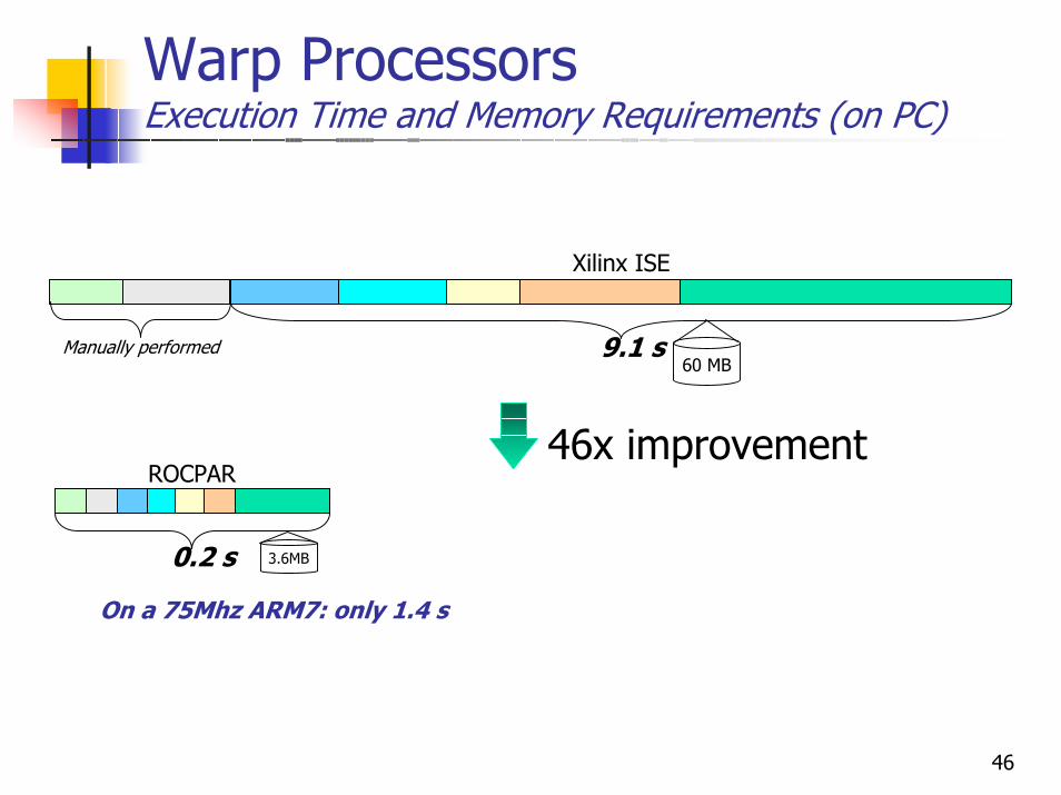
Warp Processors Execution Time and Memory Requirements (on PC)
3.6MB0.2 s
ROCPAR
60 MB9.1 s
Xilinx ISE
Manually performed
46x improvement
On a 75Mhz ARM7: only 1.4 s
47
Current/Future WorkExtending Warp Processors
Multiple software loops to hardware Handling custom sequential logicBetter synthesis, placement, routing
JIT FPGA CompilationIdea: standard binary for FPGA
Similar benefits as standard binary for microprocessore.g., portability, transparency, standard tools
48
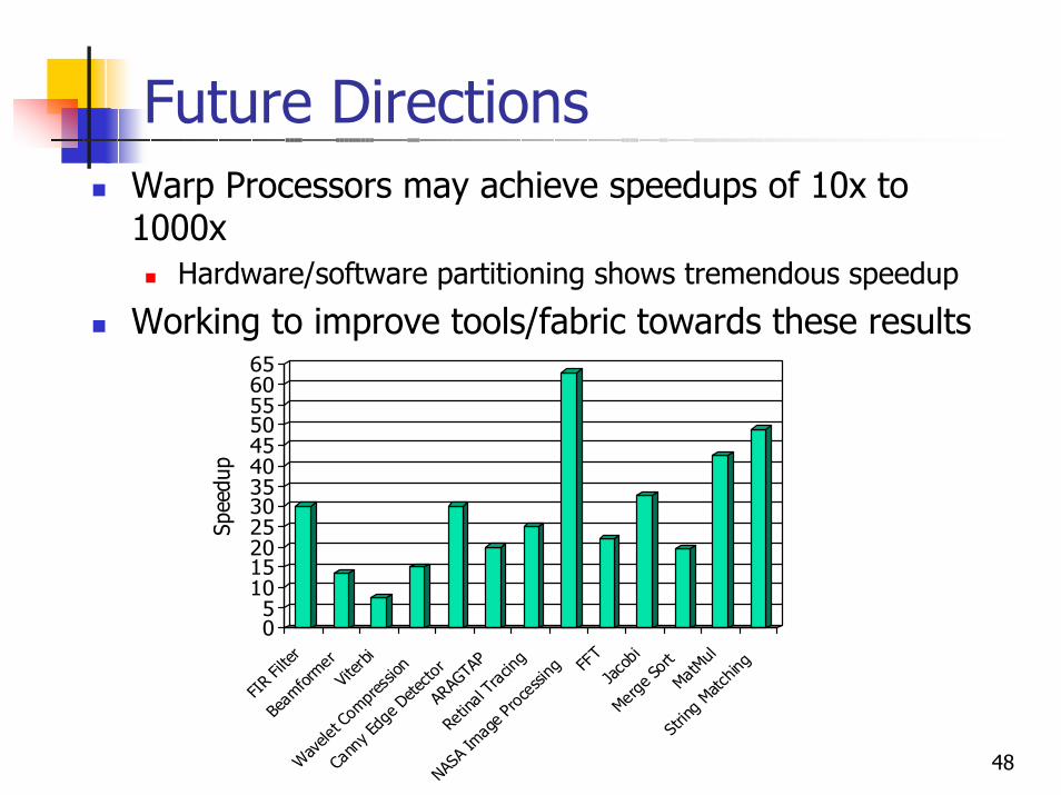
Future DirectionsWarp Processors may achieve speedups of 10x to 1000x
Hardware/software partitioning shows tremendous speedup
Working to improve tools/fabric towards these results
05
101520253035404550556065
Spee
dup
FIR
Filter
Beam
formerVit
erbi
Wav
elet C
ompr
essio
n
Cann
y Edg
e Dete
ctor
ARAG
TAP
Retin
al Tr
acing
NASA
Imag
e Pro
cessi
ng FFT
Jaco
biMer
ge So
rtMat
Mul
Strin
g Matc
hing
49
PublicationsA Configurable Logic Architecture for Dynamic Hardware/Software Partitioning, R.Lysecky and F. Vahid, Design Automation and Test in Europe Conference (DATE), February 2004.Frequent Loop Detection Using Efficient Non-Intrusive On-Chip Hardware, A. Gordon-Ross and F. Vahid, ACM/IEEE Conf. on Compilers, Architecture andSynthesis for Embedded Systems (CASES), 2003; to appear in special issue “Best of CASES/MICRO” of IEEE Trans. on Comp.A Codesigned On-Chip Logic Minimizer, R. Lysecky and F. Vahid, ACM/IEEE ISSS/CODES conference, 2003.Dynamic Hardware/Software Partitioning: A First Approach. G. Stitt, R. Lyseckyand F. Vahid, Design Automation Conference, 2003.On-Chip Logic Minimization, R. Lysecky and F. Vahid, Design Automation Conference, 2003.The Energy Advantages of Microprocessor Platforms with On-Chip Configurable Logic, G. Stitt and F. Vahid, IEEE Design and Test of Computers, November/December 2002.Hardware/Software Partitioning of Software Binaries, G. Stitt and F. Vahid, IEEE/ACM International Conference on Computer Aided Design, November 2002.