water heated condenser pump1 double spacing
TRANSCRIPT

1
1. Introduction
The process of improving the performance of a heat transfer system is
referred to as heat transfer augmentation, enhancement or intensification. In
general, this means an increase in heat transfer coefficient. A comprehensive
survey on hea t transfer augmentation is given by Bergles. [1] According to
him, heat transfer augmentation has been of interest since the earliest
documented studies of heat transfer. An example of this is Newton [2], who in
1701 suggested an effective way of increasing convective heat transfer “... not
in a calm air, but in a wind that blew uniformly upon it ...”. Even Joule [3]
reported in 1861 significant improvement in the overall heat transfer
coefficient for in- tube condensation of steam when a wire, spiralled aro und
the condenser tube, was inserted in the cooling water jacket.
According to Whitham [4], the efficiency of fire- tube boilers could be
increased by up to 18% when “retarders” or twisted- tape inserts were inserted
in the tube. It was suggested that the inserts should be used only when “the
boiler plant is pushed and the draught is strong”. In one of the first systematic
studies by Jakob and Fritz [5] on nucleate boiling, enhanced surfaces were
used. Patents dealing with enhanced heat exchangers date back to the 1920s
where fins were used on the shell side of a shell- in- tube heat exchanger. [6]
Furthermore, manufacturer’s literature [7] on heat transfer augmentation in
heat exchangers dates back to 1921, where an increase of the hot water
heating capacity of 50% was claimed as a result of enhancing both the tube-
side single- phase flow and the shell-side condensing of steam.
2
The techniques [8-9] of improving heat transfer can be classified as
passive methods which require no direct application of external power, and
active schemes which require external power. Passive techniques include
treated surfaces, rough surfaces, extended surfaces, displacement
enhancement devices, swirl f low devices, surface tension devices and fluid
additives. The active techniques include mechanical aids, surface vibration,
fluid vibration, electrostatic fields, injection, and suction. These techniques
can also be utilised simultaneously (compound augmentation). The
effectiveness of a given augmentation technique depends largely on the mode
of heat transfer or the type of heat exchanger to which it is applied as well as
the pressure drop over the given device that creates the enhancement.
Some types of heat exchangers used are found in residential and
commercial space heating and air-conditioning, residential and commercial
water heating and industrial petrochemical processing, which contributes to
more than a third of energy used [10] in the United States. Given that energy
is currently being used in the United States at a rate roughly equivalent to
39.8 million barrels of oil per day, [11] an efficiency improvement of 10% in
the cited applications by using heat transfer augmentation would save about
1.5 million barrels of oil per day, and reduce atmospheric CO2 emissions by
about 400 million metric tons per year. [12] Therefore, heat transfer
augmentation of evaporation and condensation for refrigeration,
air-conditioning and heat pump applications has received increasing attention
in recent years. This is due not only to an emphasis on energy efficiency, but

3
also a need for more compact and lighter heat exchangers packaging, possible
reductions in the charges of refrigeration gases, as well as the phasing out
programme since the end of 1995 of chlorofluorocarbon (CFC) refrigerants as
stipulated by the Montreal Protocol and later the Copenhagen and Vienna
amendments. [13]
According to Johannsen and Kaiser [14], 6% of South Africa’s primary
energy consumption could be saved if heat pumps were used to their full
technical potential. Although there is world-wide interest in the use of heat
pumps and considerable effort has been expended on heat-pump research, heat
pumps are not commonly used in South Africa.
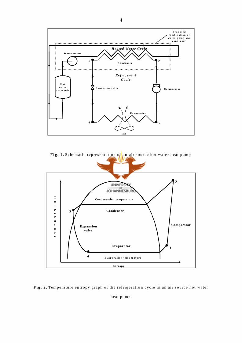
In air source hot water heat pumps, two heat exchangers are used. One
is an air- heated fin-and- tube evaporator with the colder refrigerant flowing
inside the tubes and the warmer air moving over the tubes and fins in a
cross- flow configuration. The other heat exchanger is a water-cooled
condenser, either a tube- in- tube, shell- in- tube, coil- in- shell, plate heat
exchanger, and lately fluted- tube heat exchanger. Tube- in- tube heat
exchangers are inexpensive and easy to manufacture but not very effective. A
typical set- up for a hot water heat pump is shown in Fig. 1 with the
temperature entropy graph of the refrigerant cycle given in Fig. 2 .
4
W a t e r p u m p
H o tw a t e r
r e s e r v o i rE x p a n s i o n v a l v e C o m p r e s s o r
C o n d e n s e r
E v a p o r a t o r
Refr igerantCycle
Hea ted Water Cyc le
14
3 2
Fan
P r o p o s e dc o m b i n a t i o n o fw a t e r p u m p a n d
c o n d e n s e r
F i g . 1 . Schemat ic represen ta t ion o f an a i r source ho t wa te r hea t pump
Entropy
Temperature
Condensat ion temperature
Evaporat ion t emperature
Expansionvalve
Condenser
Evaporator
Compressor
2
1
3
4
F i g . 2 . Tempera tu re en t ropy g raph o f the r e f r ige ra t io n cyc le in an a i r source ho t wa te r
heat pump
5
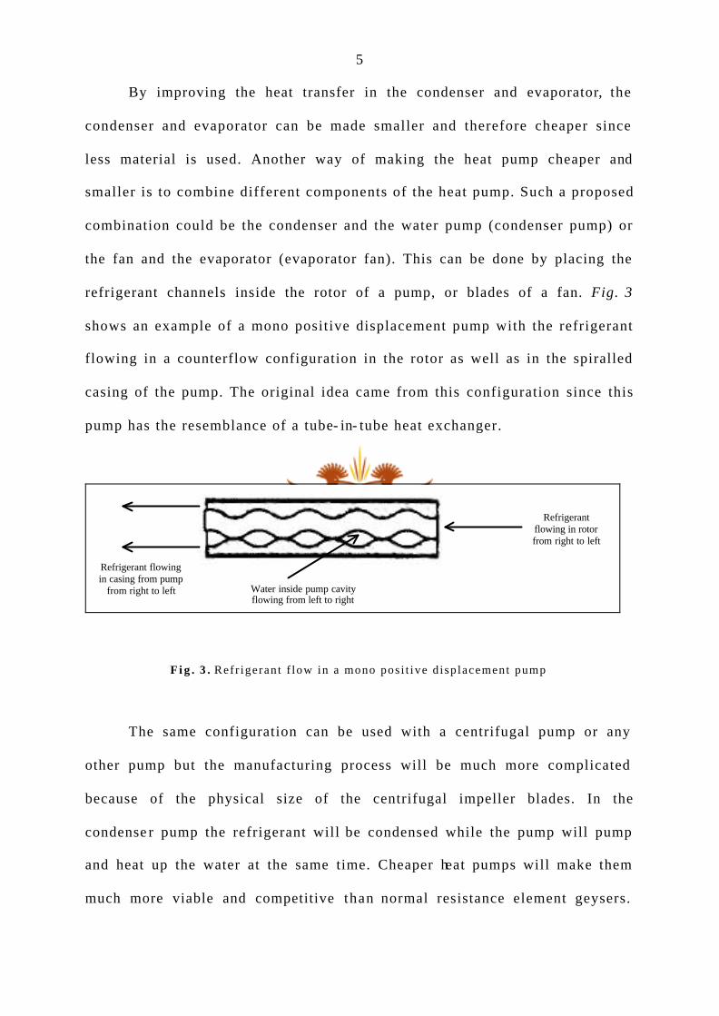
By improving the heat transfer in the condenser and evaporator, the
condenser and evaporator can be made smaller and therefore cheaper since
less material is used. Another way of making the heat pump cheaper and
smaller is to combine different components of the heat pump. Such a proposed
combination could be the condenser and the water pump (condenser pump) or
the fan and the evaporator (evaporator fan). This can be done by placing the
refrigerant channels inside the rotor of a pump, or blades of a fan. Fig. 3
shows an example of a mono positive displacement pump with the refrigerant
flowing in a counterflow configuration in the rotor as well as in the spiralled
casing of the pump. The original idea came from this configuration since this
pump has the resemblance of a tube- in- tube heat exchanger.
Water inside pump cavityflowing from left to right
Refrigerantflowing in rotorfrom right to left
Refrigerant flowingin casing from pump
from right to left
F i g . 3 . Ref r igeran t f low in a mono pos i t ive d i sp lacement pump
The same configuration can be used with a centrifugal pump or any
other pump but the manufacturing process will be much more complicated
because of the physical size of the centrifugal impeller blades. In the
condense r pump the refrigerant will be condensed while the pump will pump
and heat up the water at the same time. Cheaper heat pumps will make them
much more viable and competitive than normal resistance element geysers.

6
This method of combination can be seen as an active method of heat transfer
augmentation, but the difference is that the external power source is not in
addit ion to the existing system.
In order to investigate such a condenser pump the first step is to obtain
a specific application in which the condenser pump can be used. This is
important since pumps are used for specific applications with different flow
rates relative to a specific pressure rise. Conceptual ideas (Appendix A) were
considered in terms of viability of manufacturing and cost. After careful
consideration and refinement , it was decided to use a rotary lobe pump as the
first prototype (Appendix B) to investigate the viability of a condenser pump.
The rotary lobe pump consists of two contra-rotating rotors. The product is
moved gently through the pump with a non-pulsating low-shear action. All
wetted parts are made from 316 stainless steel and are basically the pump
casing, two lobes and a front cover for easy access to the pumping chamber.
The front cover and pump casing are two separate units which make it
possible to place refrigerant channels in each part separately. This is different
from, for example , a centrifugal pump which has one cast casing unit.
In order to simplify the manufacturing process it was decided to place
heating channels only in the front cover at first. If insufficient heat transfer
was obtained, heating channels would be placed in the pump casing and, as a
last resort, in the lobe, which would result in high-cost mechanical seals. Fig.
4 shows the rotary lobe pump with heating channels in the front cover.

7
F i g . 4 . Ro ta ry lobe pump wi th hea t ing channe l s in f ron t cover p la te
In order to obtain a counterflow configuration the flow in the heating
channels is arranged as in Fig. 4, while the top lobe is rotating clockwise and
therefore the bottom lobe anticlockwise. In the analys is of the heat transfer
the simplified model can be represented in Fig. 5. I t is a half round heating
channel with heat transfer only from the flat surface side. On the other side of
the separating plate the product is being rotated (by the rotating lobes).
Inlet
Outlet

8
R o t a t i n g p r o d u c t b e i n g p u m p e d
R e f r i g e r a n t f l o w i n g i nh e a t i n g c h a n n e l
S e c t i o n a l v i e w o fh e a t i n g c h a n n e l
T h i c k n e s s o f p l a t e c o v e r i n g h e a t i n g c h a n n e l s
H e a t t r a n s f e r t or o t a t i n g p r o d u c t
W i d t h o f p l a t e
F i g . 5 . Sec t iona l d rawing o f hea t t r ans fe r geomet ry
After an extensive literature survey on flow in non-circular tubes it was
found that heat transferred from the semicircular duct has been explored.
However, but the case where the circular section is adiabatic with only heat
transfer from the flat side could not be found in literature. A comprehensive
and excellent summary of different geometr ies was found in the Handbook of
Single -Phase Convective Heat Transfer [15]. Another important fact that
makes this geome try unique is that the heating channel is vertical and curved
(S-shaped). Correspondence [16-17] was made with leading researchers in
heat transfer and to their knowledge there is no literature on a semicircular
tube where fluid is rotated on the opposite side. Very little research has also
been done on semicircular heat exchangers with turbulent flow.

9
In the light of the previous discussion the purpose of this study is to
determine expressions for characteristics such as heat transfer coefficients
and pressure drop for this principal, semicircular geometry. The research
focuses on semicircular heat exchangers with turbulent flow in order to make
the design of such a rotary lobe condenser pump possible.
10
2. Experimental set-up
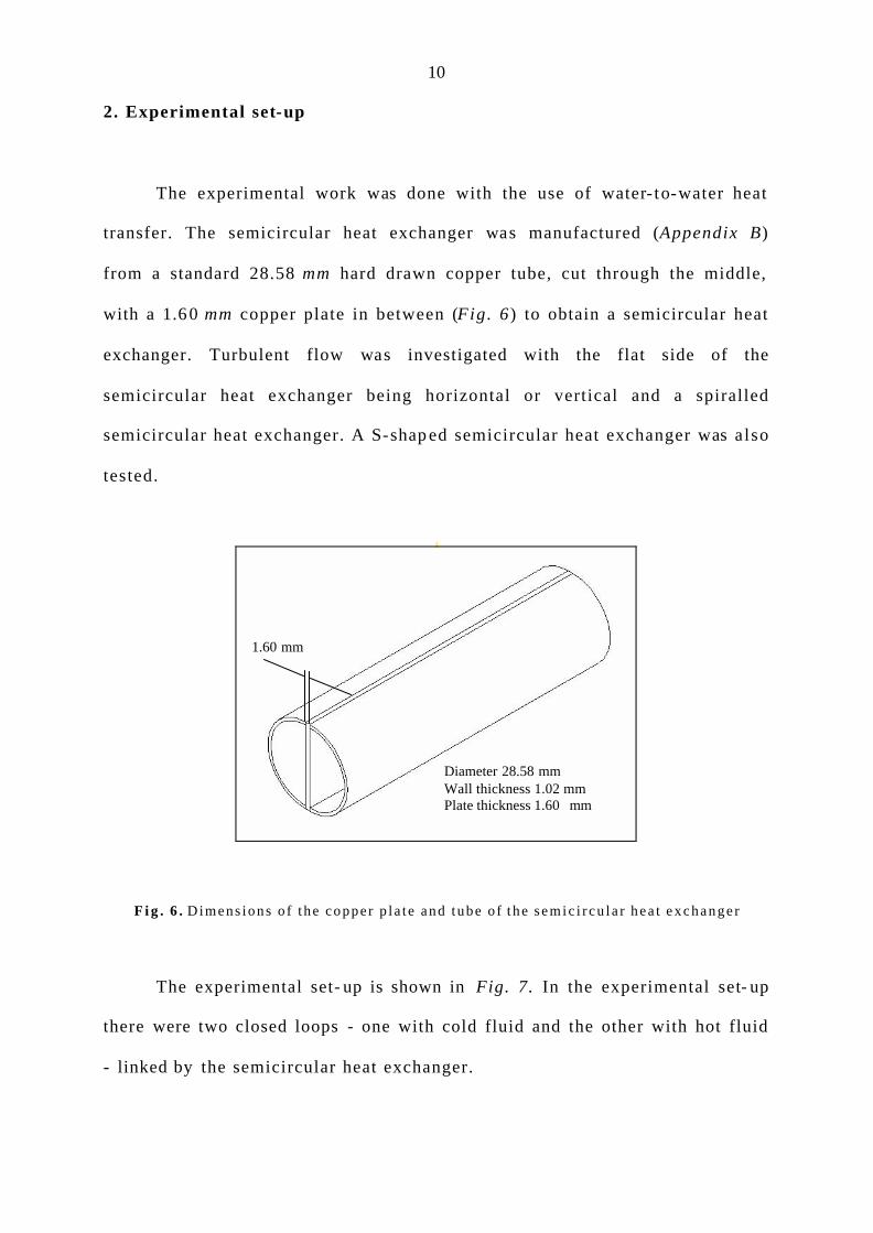
The experimental work was done with the use of water- to-water heat
transfer. The semicircular heat exchanger was manufactured (Appendix B)
from a standard 28.58 mm hard drawn copper tube, cut through the middle,
with a 1.6 0 mm copper plate in between (Fig. 6) to obtain a semicircular heat
exchanger. Turbulent flow was investigated with the flat side of the
semicircular heat exchanger being horizontal or vertical and a spiralled
semicircular heat exchanger. A S-shap ed semicircular heat exchanger was also
tested.
F i g . 6 . D imens ions o f t he coppe r p l a t e and tube o f t h e s e m i c i r c u l a r h e a t e x c h a n g e r
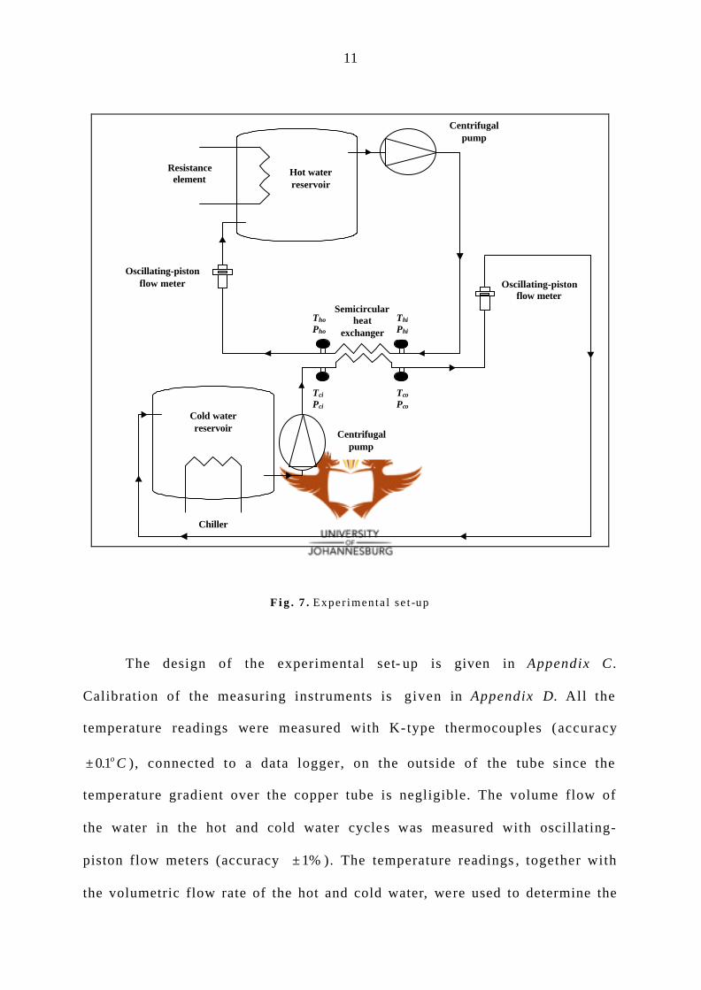
The experimental set- up is shown in Fig. 7. In the experimental set- up
there were two closed loops - one with cold fluid and the other with hot fluid
- linked by the semicircular heat exchanger.
Diameter 28.58 mm Wall thickness 1.02 mm Plate thickness 1.60 mm
1.60 mm
11
Resistanceelement
Hot waterreservoir
Centrifugalpump
Semicircularheat
exchanger
Chiller
Cold waterreservoir
Oscillating-pistonflow meter
Tco
Pco
Tci
Pci
Tho
Pho
Thi
Phi
Centrifugalpump
19765.6543
19765.6543
Oscillating-pistonflow meter
F i g . 7 . Exper imenta l se t -up
The design of the experimental set- up is given in Appendix C .
Calibration of the measuring instruments is given in Appendix D. All the
temperature readings were measured with K-type thermocouples (accuracy
± 01. o C ), connected to a data logger, on the outside of the tube since the
temperature gradient over the copper tube is negligible. The volume flow of
the water in the hot and cold water cycle s was measured with oscillating-
piston flow meters (accuracy ± 1% ). The temperature readings , together with
the volumetric flow rate of the hot and cold water, were used to determine the
12
heat transfer between the hot and cold fluid. This was used to determine the
energy balance over the heat exchanger. The experimental results were
analysed using the Wilson plot method to determine the heat transfer
coefficients of the semicircular geometry.
In order to calculate the energy balance , the equations to determine the
properties of water were obtained from literature [18] (Appendix E). In order
to compare the semicircular heat exchanger with existing heat exchangers a
theoretical analys is (Appendix F) was done on a normal round tube- in- tube
heat exchanger with equal hydraulic diameter to that of the semicircular heat
exchanger.
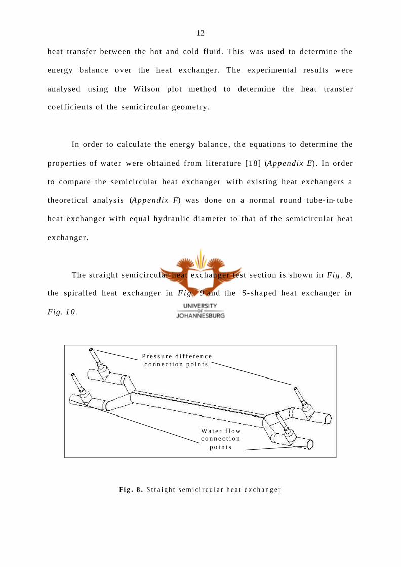
The straight semicircular heat exchanger test section is shown in Fig. 8,
the spiralled heat exchanger in F i g . 9 and the S-shaped heat exchanger in
Fig. 10.
Fi g . 8 . S t r a i g h t s e m i c i r c u l a r h e a t e x c h a n g e r
W a t e r f l o w c o n n e c t i o n
p o i n t s
P r e s s u r e d i f f e r e n c e c o n n e c t i o n p o i n t s

13
F i g . 9 . S p i r a ll ed s emic i r cu l a r hea t exchange r
F i g . 1 0 . S -s h ape semic i r cu la r hea t exchanger
950 mm
14
3. Results
3.1 Heat transfer
Results of experiments done on a semicircular heat exchanger are given
in Appendix G. Experiments wer e done with the separating plate between the
two semicircles in a vertical as well as horizontal orientation for the straight
heat exchanger. Experiments were conducted in each case with hot water a t
the bottom or top and inside or outside spiral in order to determine all
possible variations. The experimental results wer e analysed using the
modified Wilson plot technique [19] and are given in Appendix H.
The results for the modified Wilson plot Eq. 1 and 2 (Sieder- Tate) [20]
are given in Table 1.
Nuh D
kCh
h h
hh h
Ph
w h
= =
Re Pr1 3
0.14µµ
(1)
Nuh D
kCc
c c
cc c
Pc
w c
= =
Re Pr
.
1 3
0 14µ
µ (2)

15
T a b l e 1 . Summary o f resu l t s f rom modi f i ed Wi l son p lo t ana lys i s
P Ch Cc U Average % Error
Plate vertical 0.6585 0.1564 0.1359 0.692
Plate horizontal hot water bottom 0.6706 0.1344 0.1359 0.583
Plate horizontal hot water top 0.6303 0.2035 0.1933 0.594
Spiral hot water outside 0.7245 0.0848 0.0971 0.714
Spiral hot water inside 0.7363 0.0829 0.0673 0.313
S-shape 0.7220 0.0902 0.0904 0.607
The median and standard deviation given in Table 1 are for the
percentage difference between the overall heat transfer coefficient calculated
with the logarithmic mean temperature difference and with the results from
the modified Wilson plot technique. As expected, the hot and cold water
coefficients are very similar since the cross- flow areas are equal.
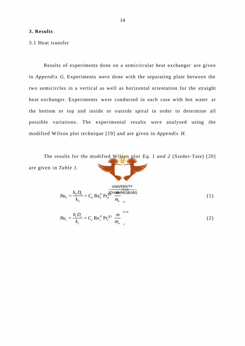
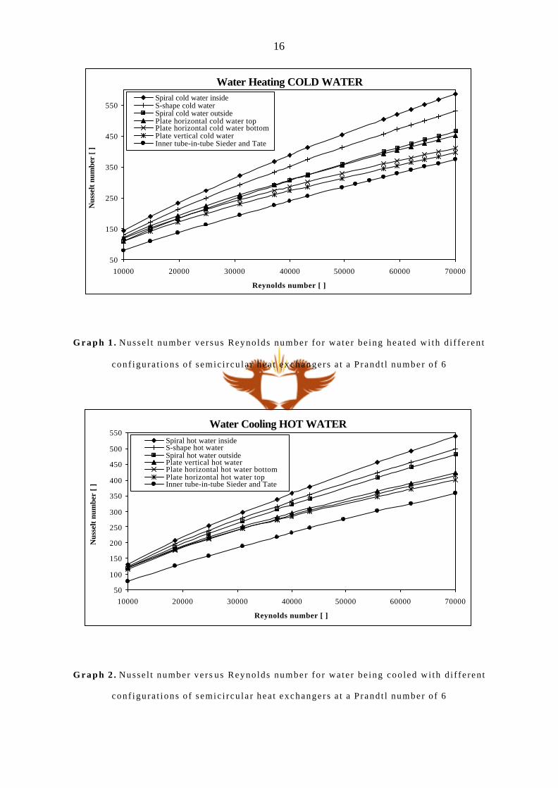
Graph s 1 and 2 show the results of the Nusselt number relative to the
Reynolds number for different configurations of the semicircular heat
exchanger. These graphs are constructed with the Wilson plot correlations
obtained. Both graphs are calculated at a Prandtl number of 6 (average
temperature 25.65 o C ) in order to compare the difference between the hot and
cold water in each of the semicircular sections.
16
Water Heating COLD WATER
50
150
250
350
450
550
10000 20000 30000 40000 50000 60000 70000
Reynolds number [ ]
Nus
selt
num
ber
[ ]Spiral cold water insideS-shape cold waterSpiral cold water outsidePlate horizontal cold water topPlate horizontal cold water bottomPlate vertical cold water Inner tube-in-tube Sieder and Tate
G r a p h 1 . Nusse l t number ve r sus Reyno lds number fo r wa te r be ing hea ted wi th d i f f e ren t
con f igu ra t ions o f s emic i r cu la r hea t exchange r s a t a P rand t l number o f 6
Water Cooling HOT WATER
50
100
150
200
250
300
350
400
450
500
550
10000 20000 30000 40000 50000 60000 70000
Reynolds number [ ]
Nus
selt
num
ber
[ ]
Spiral hot water insideS-shape hot waterSpiral hot water outsidePlate vertical hot waterPlate horizontal hot water bottomPlate horizontal hot water topInner tube-in-tube Sieder and Tate
G r a p h 2 . Nusse l t number ve r s us Reyno lds number fo r wa te r be ing coo led wi th d i f f e ren t
con f igu ra t ions o f s emic i r cu la r hea t exchange r s a t a P rand t l number o f 6
17
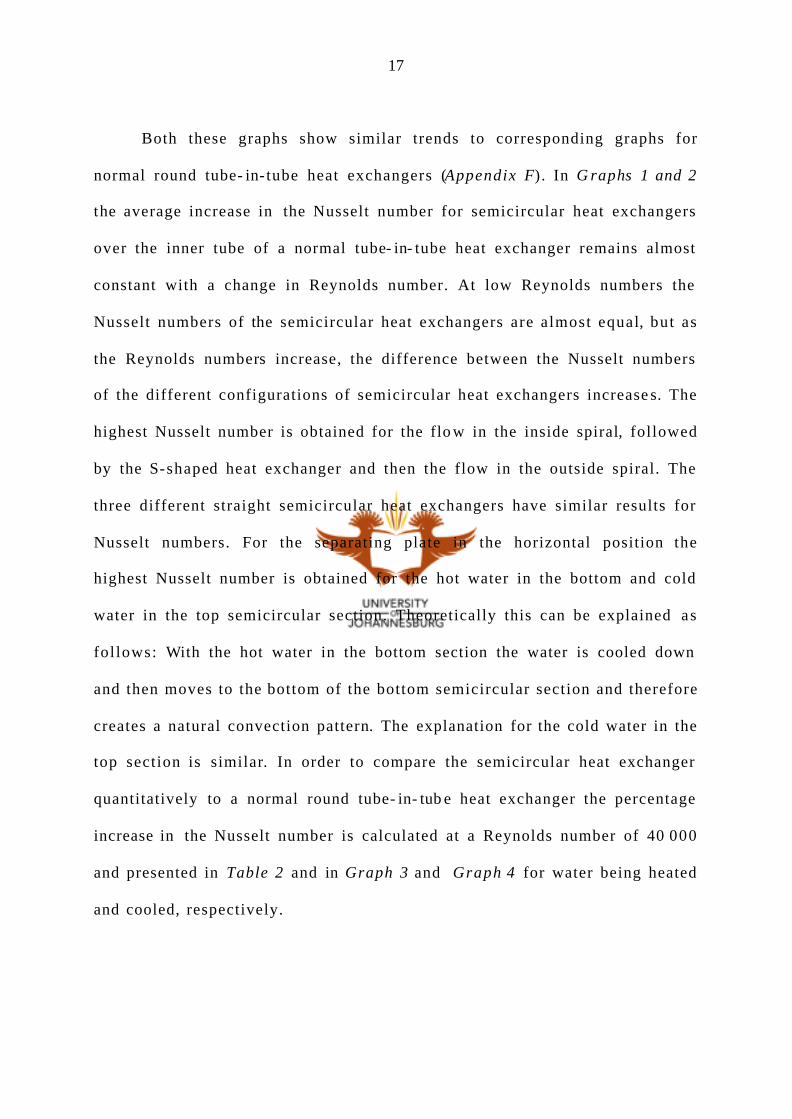
Both these graphs show similar trends to corresponding graphs for
normal round tube- in- tube heat exchangers (Appendix F). In G raphs 1 and 2
the average increase in the Nusselt number for semicircular heat exchangers
over the inner tube of a normal tube- in- tube heat exchanger remains almost
constant with a change in Reynolds number. At low Reynolds numbers the
Nusselt numbers of the semicircular heat exchangers are almost equal, but as
the Reynolds numbers increase, the difference between the Nusselt numbers
of the different configurations of semicircular heat exchangers increase s. The
highest Nusselt number is obtained for the flo w in the inside spiral, followed
by the S-shaped heat exchanger and then the flow in the outside spiral. The
three different straight semicircular heat exchangers have similar results for
Nusselt numbers. For the separating plate in the horizontal position the
highest Nusselt number is obtained for the hot water in the bottom and cold
water in the top semicircular section. Theoretically this can be explained as
follows: With the hot water in the bottom section the water is cooled down
and then moves to the bottom of the bottom semicircular section and therefore
creates a natural convection pattern. The explanation for the cold water in the
top section is similar. In order to compare the semicircular heat exchanger
quantitatively to a normal round tube- in- tub e heat exchanger the percentage
increase in the Nusselt number is calculated at a Reynolds number of 40 000
and presented in Table 2 and in Graph 3 and Graph 4 for water being heated
and cooled, respectively.
18
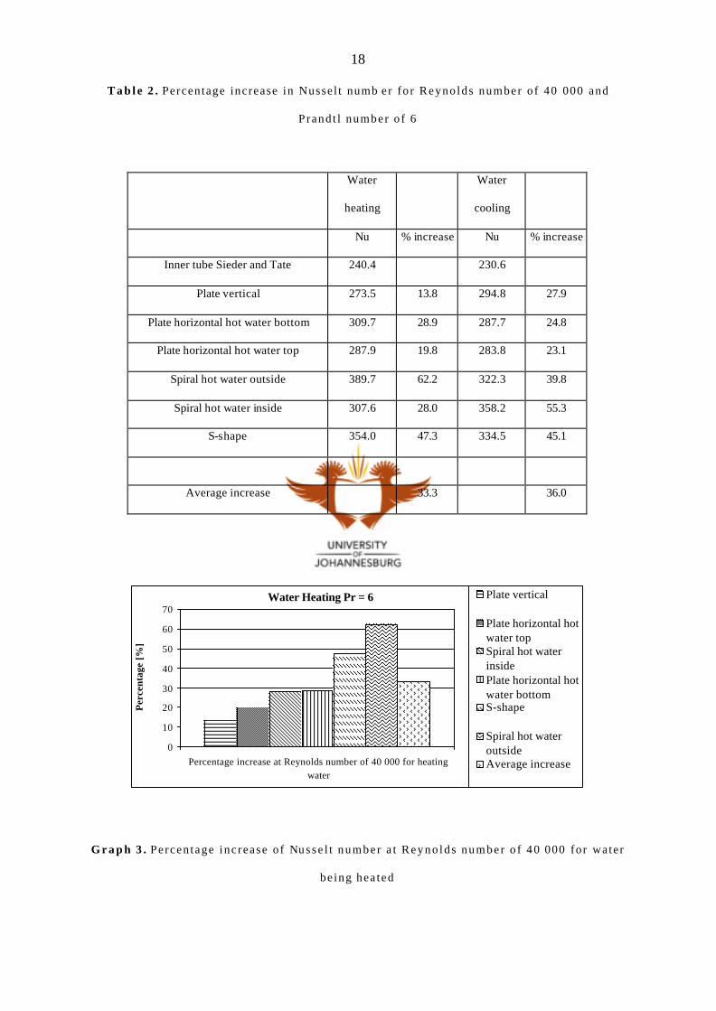
T a b l e 2 . Percentage increase in Nussel t numb er fo r Reyno lds number o f 40 000 and
Prand t l number o f 6
Water
heating
Water
cooling
Nu % increase Nu % increase
Inner tube Sieder and Tate 240.4 230.6
Plate vertical 273.5 13.8 294.8 27.9
Plate horizontal hot water bottom 309.7 28.9 287.7 24.8
Plate horizontal hot water top 287.9 19.8 283.8 23.1
Spiral hot water outside 389.7 62.2 322.3 39.8
Spiral hot water inside 307.6 28.0 358.2 55.3
S-shape 354.0 47.3 334.5 45.1
Average increase 33.3 36.0
Water Heating Pr = 6
0
10
20
30
40
50
60
70
Percentage increase at Reynolds number of 40 000 for heatingwater
Per
cent
age
[%]
Plate vertical
Plate horizontal hotwater topSpiral hot waterinsidePlate horizontal hotwater bottomS-shape
Spiral hot wateroutsideAverage increase
G r a p h 3 . Pe rcen tage inc rease o f Nusse l t number a t Reyno lds number o f 40 000 for water
be ing hea ted
19
Water Cooling Pr = 6
0
10
20
30
40
50
60
Percentage increase at Reynolds number of 40 000 for coolingwater
Per
cent
age
[%]
Plate horizontal hotwater topPlate horizontal hotwater bottomPlate vertical
Spiral hot wateroutsideS-shape
Spiral hot waterinsideAverage increase
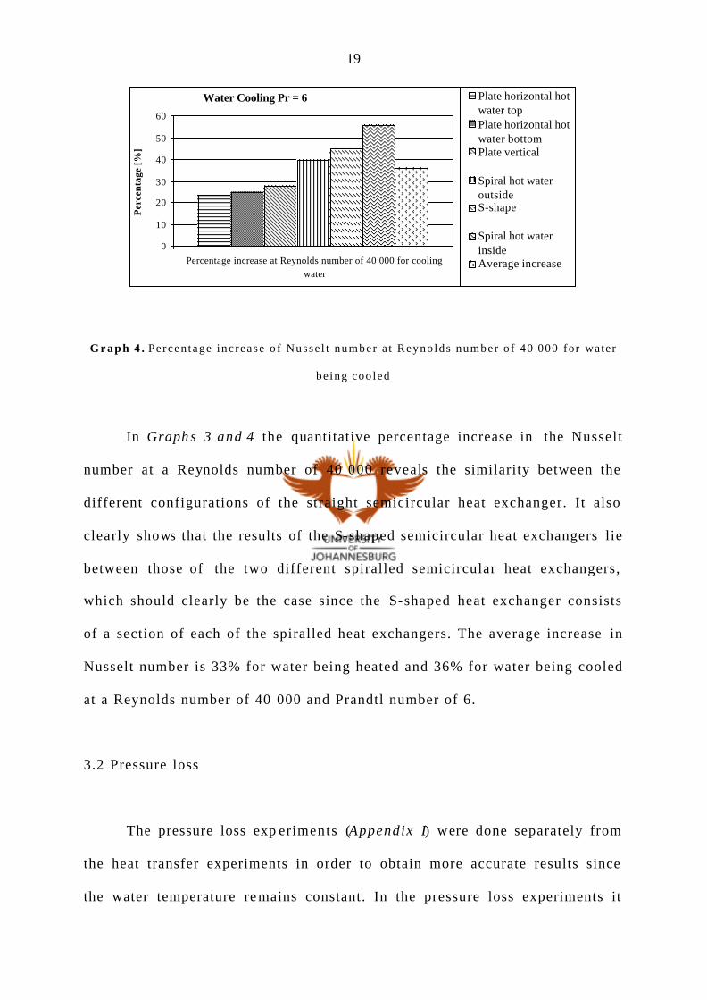
G r a p h 4 . Pe rcen tage inc rease o f Nusse l t number a t Reyno lds number o f 40 000 for water
be ing coo led
In Graph s 3 and 4 the quantitative percentage increase in the Nusselt
number at a Reynolds number of 40 000 reveals the similarity between the
different configurations of the straight semicircular heat exchanger. It also
clearly shows that the results of the S-shaped semicircular heat exchangers lie
between those of the two different spiralled semicircular heat exchangers,
which should clearly be the case since the S-shaped heat exchanger consists
of a section of each of the spiralled heat exchangers. The average increase in
Nusselt number is 33% for water being heated and 36% for water being cooled
at a Reynolds number of 40 000 and Prandtl number of 6.
3.2 Pressure loss
The pressure loss exp eriments (Appendix I) were done separately from
the heat transfer experiments in order to obtain more accurate results since
the water temperature re mains constant. In the pressure loss experiments it
20
was found that care must be taken to ensure that no air is trapped in the
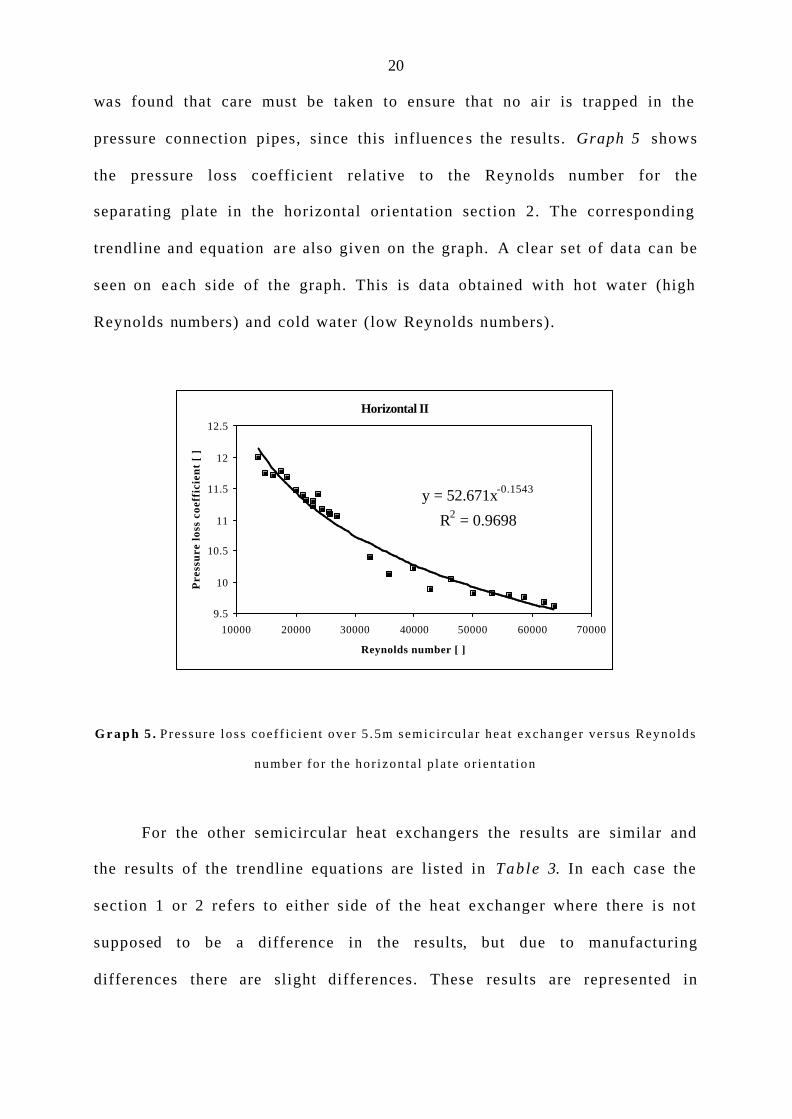
pressure connection pipes, since this influence s the results. Graph 5 shows
the pressure loss coefficient relative to the Reynolds number for the
separating plate in the horizontal orientation section 2. The corresponding
trendline and equation are also given on the graph. A clear set of data can be
seen on each side of the graph. This is data obtained with hot water (high
Reynolds numbers) and cold water (low Reynolds numbers).
Horizontal II
y = 52.671x-0.1543
R2 = 0.9698
9.5
10
10.5
11
11.5
12
12.5
10000 20000 30000 40000 50000 60000 70000
Reynolds number [ ]
Pre
ssu
re lo
ss c
oeff
icie
nt
[ ]
G r a p h 5 . P ressu re loss coe f f i c i en t ove r 5 .5m semic i rcu la r hea t exchanger ve r sus Reyno lds
number fo r the hor izon ta l p la te o r ien ta t ion
For the other semicircular heat exchangers the results are similar and
the results of the trendline equations are listed in Table 3. In each case the
section 1 or 2 refers to either side of the heat exchanger where there is not
supposed to be a difference in the results, but due to manufacturing
differences there are slight differences. These results are represented in
21
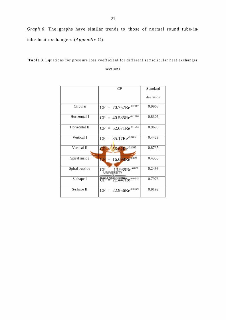
Graph 6. The graphs have similar trends to those of normal round tube- in-
tube heat exchangers (Appendix G).
T a b l e 3 . Equa t ions fo r p ressure loss coe f f i c i en t fo r d i f f e ren t semic i rcu la r hea t exchanger
sec t ions
CP Standard
deviation
Circular CP = 70.757Re -0.2117 0.9963
Horizontal I CP = 40.585Re -0.1216 0.8305
Horizontal II CP = 52.671Re -0.1543 0.9698
Vertical I CP = 35.17Re -0.1064 0.4429
Vertical II CP = 56.62Re -0.1545 0.8735
Spiral inside CP = 16.698Re -0.028 0.4355
Spiral outside CP = 13.939Re -0.022 0.2499
S-shape I CP = 21.447Re -0.0545 0.7976
S-shape II CP = 22.956Re -0.0649 0.9192

22
6
7
8
9
10
11
12
13
14
15
16
0 10000 20000 30000 40000 50000 60000 70000 80000
Reynolds number [ ]
Pre
ssur
e lo
ss c
oeff
icie
nt [
]
Circular Horizontal I Horizontal IIVertical I Vertical II Spiral insideSpiral outside S-shape I S-shape II
G r a p h 6 . P ressure loss coef f i c i en t over 5 .5m semic i rcu la r hea t exchanger ve r sus Reyno lds
number fo r d i f f e ren t semic i rcu la r hea t exchanger sec t ions
In Graph 6 all the trendlines are similar except that of the flow for the
water on the outside spiral. This is also emphasised by the low trendline
correlation of the flow in the outside spiral (Tab le 3). The reason for the
deviation in results is air in the pressure measuring connection points.
However, the experiments could not be repeated , since this experimental set-
up had been altered at the point where this was noticed. The pressure loss
coefficient correlates directly with that of the increase in Nusselt number.
The highest increase in pressure loss coefficient was obtained with the flow in
the inner spiral and similar results were produced for the three different
straight semicircular he at exchangers.
23
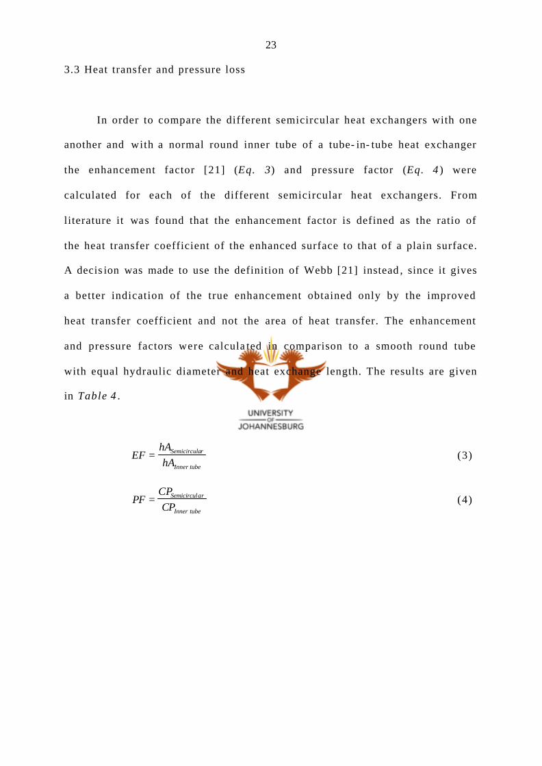
3.3 Heat transfer and pressure loss
In order to compare the different semicircular heat exchangers with one
another and with a normal round inner tube of a tube- in- tube heat exchanger
the enhancement factor [21] (Eq. 3) and pressure factor (Eq. 4 ) were
calculated for each of the different semicircular heat exchangers. From
literature it was found that the enhancement factor is defined as the ratio of
the heat transfer coefficient of the enhanced surface to that of a plain surface.
A decis ion was made to use the definition of Webb [21] instead , since it gives
a better indication of the true enhancement obtained only by the improved
heat transfer coefficient and not the area of heat transfer. The enhancement
and pressure factors were calcula ted in comparison to a smooth round tube
with equal hydraulic diameter and heat exchange length. The results are given
in Table 4 .
EFhAhA
Semicircular
Inner tube
= (3)
PFCPCP
Semicircular
Inner tube
= (4)
24
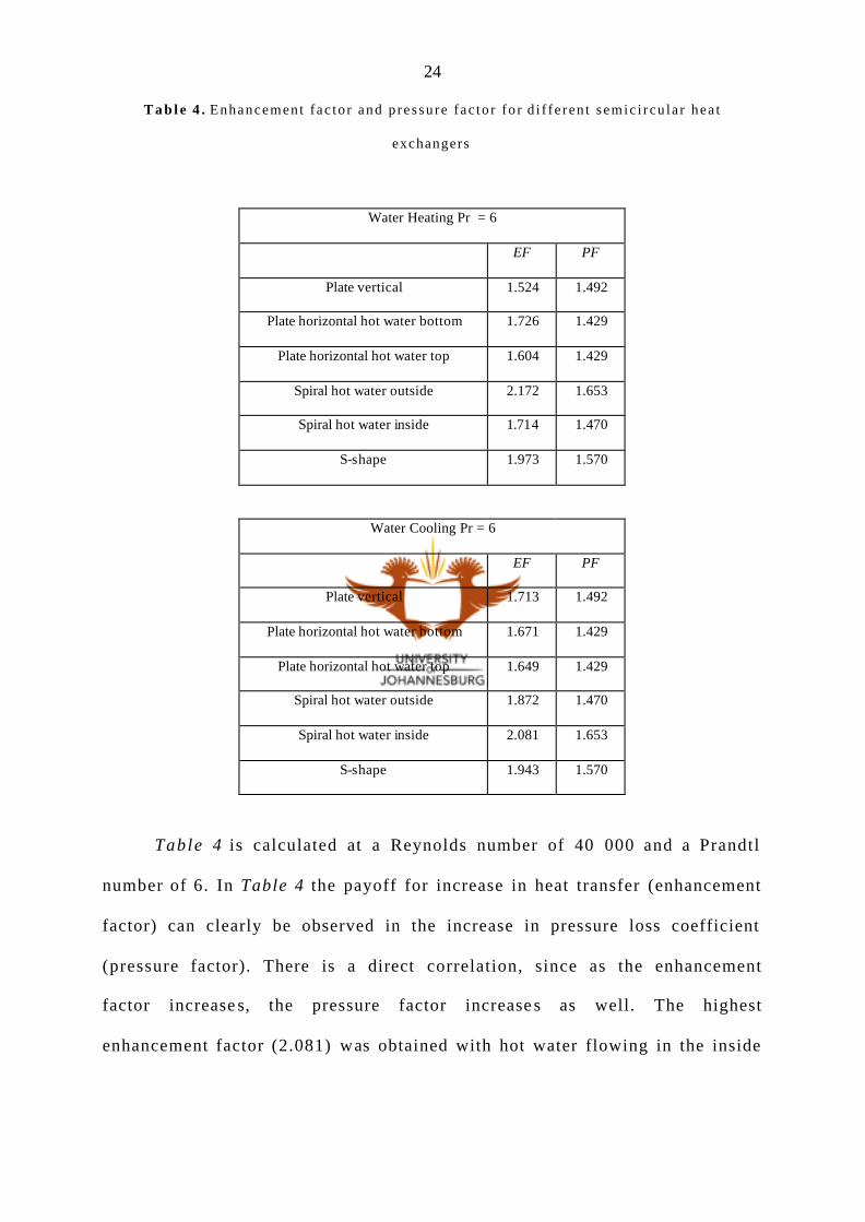
T a b l e 4 . Enhancement f ac to r and p ressu re f ac to r fo r d i f f e ren t semic i rcu la r hea t
exchangers
Water Heating Pr = 6
EF PF
Plate vertical 1.524 1.492
Plate horizontal hot water bottom 1.726 1.429
Plate horizontal hot water top 1.604 1.429
Spiral hot water outside 2.172 1.653
Spiral hot water inside 1.714 1.470
S-shape 1.973 1.570
Water Cooling Pr = 6
EF PF
Plate vertical 1.713 1.492
Plate horizontal hot water bottom 1.671 1.429
Plate horizontal hot water top 1.649 1.429
Spiral hot water outside 1.872 1.470
Spiral hot water inside 2.081 1.653
S-shape 1.943 1.570
Table 4 is calculated at a Reynolds number of 40 000 and a Prandtl
number of 6. In Table 4 the payoff for increase in heat transfer (enhancement
factor) can clearly be observed in the increase in pressure loss coefficient
(pressure factor). There is a direct correlation, since as the enhancement
factor increase s, the pressure factor increase s as well. The highest
enhancement factor (2.081) was obtained with hot water flowing in the inside

25
spiral but the highest pressure factor (1.653) was also obtained with this
configuration.
4. Discussion of results
4.1 Heat transfer
There is a significant increase in heat transfer for a semicircular heat
exchanger above a normal round tube of equal hydraulic diameter. This can be
attributed to conduction, which is much higher than convection. With the
semicircular heat exchanger an extended fin (Fig. 11.) forms , which increase s
the heat transfer characteristics.
Flowarea
Good the rmalconnect ion for
conduct ion
Extended f in incontact wi thother f lu id
F i g . 1 1 . Ex tended f in fo rmed wi th semic i rcu la r h e a t e xchanger conf igura t ion
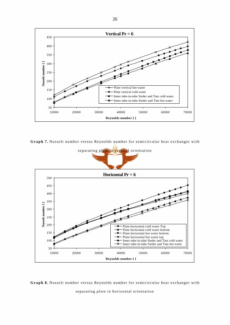
By combining Graphs 1 and 2 the difference between the hot and cold
water is represented for each of the different semicircular heat exchangers.
This combination is given in Graph s 7 – 10 for each of the different
semicircular heat exchangers.
26
Vertical Pr = 6
50
100
150
200
250
300
350
400
450
10000 20000 30000 40000 50000 60000 70000
Reynolds number [ ]
Nus
selt
num
ber
[ ]
Plate vertical hot waterPlate vertical cold water Inner tube-in-tube Sieder and Tate cold waterInner tube-in-tube Sieder and Tate hot water
G r a p h 7 . Nusse l t number ve r sus Reyno lds number fo r semic i rcu la r hea t exchanger wi th
separa t ing p la te in ve r t i ca l o r i en ta t ion
Horizontal Pr = 6
50
100
150
200
250
300
350
400
450
500
10000 20000 30000 40000 50000 60000 70000
Reynolds number [ ]
Nus
selt
num
ber
[ ]
Plate horizontal cold water TopPlate horizontal cold water bottomPlate horizontal hot water bottomPlate horizontal hot water topInner tube-in-tube Sieder and Tate cold waterInner tube-in-tube Sieder and Tate hot water
G r a p h 8 . Nusse l t number ve r sus Reyno lds number fo r semic i rcu la r hea t exchanger wi th
separa t ing p la te in hor izon ta l o r ien ta t ion

27
S-Shape Pr = 6
50
150
250
350
450
550
10000 20000 30000 40000 50000 60000 70000
Reynolds number [ ]
Nus
selt
num
ber
[ ]S-shape cold waterS-shape hot waterInner tube-in-tube Sieder and Tate cold waterInner tube-in-tube Sieder and Tate hot water
G r a p h 9 . Nusse l t number ve r sus Reyno lds number fo r S -shaped semic i r cu la r hea t
exchange r
Spiral Pr = 6
50
150
250
350
450
550
650
10000 20000 30000 40000 50000 60000 70000
Reynolds number [ ]
Nus
selt
num
ber
[ ]
Spiral cold water insideSpiral hot water insideSpiral hot water outsideSpiral cold water outsideInner tube-in-tube Sieder and Tate cold waterInner tube-in-tube Sieder and Tate hot water
G r a p h 1 0 . Nusse l t number ve r sus Reyno lds number fo r sp i r a l l ed semic i r cu la r hea t
exchange r

28
From the Sieder- Tate equation there should not be a difference in the
C-value for the hot and cold water in the different semicircular sections. The
C-value only change s for different flow geometries. This can be observed in
Graph s 7 – 9, where there is a small difference between the hot and cold
water results. The differences can be attributed to experimental errors and
manufacturing differences, since the hot and cold water flowed in opposite
directions in the same semicircular section. The results for the normal smooth
round tube (Graphs 7 – 10) also show a difference between the hot and cold
water because for the hot water the copper wall temperature is cold and the
inverse is true for the cold water. In Table 5 the percentage difference in the
Nusselt number at a Reynolds number of 40 000 for hot and cold water in
different semicircular heat exchangers is given.

29
T a b l e 5 . Pe rcen tage d i f fe rence in Nusse l t number a t Reyno lds number o f 40 000 fo r ho t
and co ld wa te r in d i f fe ren t semic i rcu la r hea t exchangers
Nu Nu
Water heating
cold water
Water cooling
hot water
% difference
Inner tube Sieder and Tate 240.4 230.6 4.2
Plate vertical 273.5 294.8 7.5
Plate horizontal hot water bottom 309.7 287.7 7.4
Plate horizontal hot water top 287.9 283.8 1.4
Outside spiral 307.6 322.3 4.7
Inside spiral 389.7 358.2 8.4
S-shape 354.0 334.5 5.7
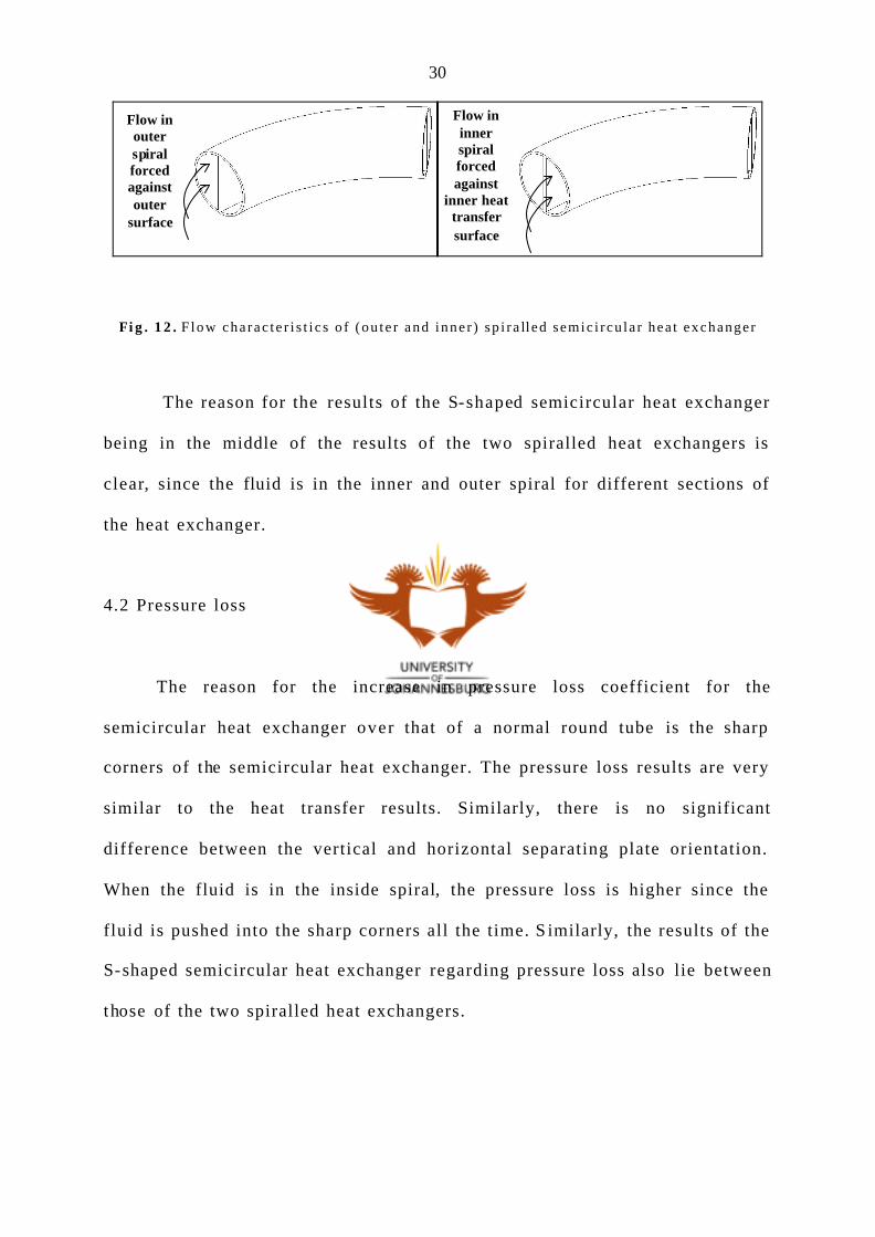
There is , however, a significant difference in the heat transfer if the
water passes in the inside or outside spiral of the spiralled heat exchanger
(Graph 10 ). In each case for hot and cold water the heat transfer is increased
with the flow in the inside spiral. This can be explained in Fig. 12. In this
figure it is clear that the flow in the inner spiral is always forced against the
heat transfer surface. This differs from the flow in the outer spiral which is
always forced against the outer surface where heat is not directly transferred
but still by means of the extended fin. This is the reason for the increase in
heat transfer of the spiralled heat exchanger over that of a straight
semicircular heat exchanger.
30
Fi g . 1 2 . F low cha rac te r i s t i c s o f (ou te r and inne r ) sp i r a ll ed semic i rcu la r hea t exchanger
The reason for the results of the S-shaped semicircular heat exchanger
being in the middle of the results of the two spiralled heat exchangers is
clear, since the fluid is in the inner and outer spiral for different sections of
the heat exchanger.
4.2 Pressure loss
The reason for the increase in pressure loss coefficient for the
semicircular heat exchanger over that of a normal round tube is the sharp
corners of the semicircular heat exchanger. The pressure loss results are very
similar to the heat transfer results. Similarly, there is no significant
difference between the vertical and horizontal separating plate orientation.
When the fluid is in the inside spiral, the pressure loss is higher since the
fluid is pushed into the sharp corners all the time. S imilarly, the results of the
S-shaped semicircular heat exchanger regarding pressure loss also lie between
those of the two spiralled heat exchangers.
Flow in outer spiral forced against outer
surface
Flow in inner spiral forced against
inner heat transfer surface

31
5. Conclusio n
In this study expressions for heat transfer coefficients and pressure loss
coefficients, for a semicircular geometry in different orientations, were
determined. The research focuses on semicircular heat exchangers with
turbulent flow in order to make the design of a rotary lobe condenser pump
possible.
There is a significant increase in heat transfer for semicircular heat
exchangers ove r the inner tube of a normal tube- in- tube heat exchanger with
equal hydraulic diameter. Quanti tat ively the averag e increase in the Nusselt
number is 33% for water being heated and 36% for water being cooled at a
Reynolds number of 40 000 and Prandtl number of 6. Unfortunately, the
pressure loss increase s by an equal amount. The highest enhancement factor
(highest increase in heat transfer coefficient) and pressure factor (highest
increase in pressure loss coefficient) were obtained with the flow of water in
the inner spiral of the spiralled semicircular heat exchanger.
Due to the equal increase in heat transfer coeffic ient and pressure loss
coefficient, it can be concluded that it would not be viable to use semicircular
heat exchangers instead of normal round tube- in- tube heat exchangers in
normal situations. This is mainly due to a difficult manufacturing process.
Use of semicircular heat exchangers could , however, be made much easier
with an extrusion process, for example .

32
Semicircular heat exchange channels would be very suitable for
combined condenser pumps, with the increase in heat transfer. There is an
increase in pressure loss but the determining gain is a much smaller system.
For the design of the combined condenser pump more experiments need to be
conducted with refrigerant in a semicircular heat exchanger. For the practical
application it is believed that a conservative practical answer can be obtained
by using the theory for normal round tubes. With this approach the design of
such a combined condenser pump would be possible.
The results obtained in this study could be used to verify a
computational fluid dynamics (CFD) model. Then CFD model could then be
expanded to different diameters of pipe and even more configurations of
semicircular heat exchangers.
This research could also be expanded to the combined evaporator or
condenser fan to either cool or heat air that is being blown by a fan.

33
6. References
[1] Bergles AE. Some perspectives on enhanced heat transfer - second
generation heat transfer technology . Journal of Heat Transfer, November
1988, 110, 1082-1096.
[2] Newton I. “Scala graduum caloris”. The Philosophical Transactions of the
Royal Society of London, 1701, 22 (1701), 824-829, translated from the
Latin in The Philosophical Transactions of the Royal Society of London,
abridged, 1809, Vol. IV, (1694-1702), London 1809, 572-575.
[3] Joule JP. On the surfa ce - condensation of steam. Philosophical
Transactions of the Royal Society of London , 1861, 151, 133-160.
[4] Whitham JM. The effect of retarders in fin tubes of steam boilers. Street
Railway Journal , 1896, 12, 374.
[5] Jakob M & Fritz W. “Versuche über den verda mpfungsvorgang”.
Forschung auf dem Gebiete des Ingenieurwesens , 1931, 2 , 435-447.
[6] Lea RB. Oil cooler. US Patent No. 1, 367, 881 , 1921.
[7] Alberger Heater Company, Catalog No. 3, Buffalo, NY, USA, 1921.
[8] Bergles AE. Techniques to augment heat transfer , handbook of heat
transfer applications, McGraw- Hill, New York, 1985.
[9] Bergles AE. Enhancement of heat transfer. Proceedings of the 6th
International Heat Transfer Conference , 1978, 6 , 89-108.
[10] Hedley D. World Energy: The facts and the future, 2nd edn., Facts on
File Publications, New York, 1986.
[11] Krenz JH. Energy Conversion and Utilization , 2nd edn., Allyn and
Beacon, Inc., Boston, 1984.

34
[12] Hu X & Jacobi AM. Local heat transfer behaviour and its impact on a
single- row, annularly finned tube heat exchanger. Journal of Heat
Transfer, 1993, 115, 66-74.
[13] Cavallini A. Working fluids for mechanical refrigeration. International
Journal of Refrigeration, 1996, 19 (8), 485-496.
[14] Johannsen A & Kaiser G. Potential of electrically operated heat pumps
for heating water in South Africa. CSIR Rept 615 , Pretoria, 1986.
[15] Kakac S, Shah RK & Aung W. Handbook of Single -Phase Convective
Heat Transfer, John Wiley & Sons, Inc., New York, 1987.
[16] Bergles AE, Personal correspondence , 2001.
[17] Ebadian M, P ersonal correspondence , 2001.
[18] Popiel CO & Wojtkowiak J. Simple formulas for thermophysical
properties of l iquid water for heat t ransfer calculations (from 0oC to
150oC), Heat Transfer Engineering, 1998, 19, 87-101.
[19] Briggs DE & Young EH. Modified Wilson p lot techniques for obtaining
heat t ransfer correlat ions for shell and tube heat exchangers, Chem. Eng.
Prog. Symp. , Ser. 92, 1969, 65, 35-45.
[20] Incropera FP & DeWitt DP. Introduction to Heat Transfer , 3r d ed., John
Wiley & Sons, Inc., New York, USA, 1996.
[21] Webb RL. Principles of Enhanced Heat Transfer , 1st ed., John Wiley &
Sons, Inc., New York, USA, 1994.