water surface - nguyen.hong.hai.free.frnguyen.hong.hai.free.fr/ebooks/science and...
TRANSCRIPT

It is common practice to start the analysis by assuming auniform distribution of/(;c) (say/(jc) = 1.0) across the slip. Someauthors have indicated that variations in the shape of the f(x)distribution have little effect on the factor of safety determinedby the analysis, but other experience suggests that this dependsupon the geometry of the problem and the parameters used. Insome cases the f ( x ) distribution can affect the result signifi-cantly, and therefore different distributions should be used.These may take the form of either: (1) a half-sine curve; or (2) adistribution where /(X) is proportional to the curvature of theslip surface.
The output from such a computer analysis should not beaccepted without a check that:
(1) The shear stress on any vertical surface within the slip massdoes not exceed the available shear strength.
(2) No tension is implied on any vertical surface within the slipmass. For this to be true the resultant force on any sectionshould pass within the bounds of the ground surface and theslip surface.
It is therefore necessary to obtain values for the vertical shearforce and position of the resultant thrust across the section inorder to make these checks.
9.5.7.5 Flow slides
Not all slides are deep-seated shear slides. (For a classificationof landslides see Skempton and Hutchinson.53) A fairly commontype which should be mentioned is the flow slide. Flow slidesgenerally take place in saturated masses of loose, fairly imper-vious soils such as fine sands, silts or silty clays. They can occuron quite flat slopes and can travel long distances, the soil andwater flowing as a liquid mass. They are caused by a suddenreduction of the shear strength to zero, or close to it, by thetransfer of all the pressure to the water in the voids, a processknown as liquefaction. The chief factor here is the relativedensity of the soil, loose soils having a relative density of lessthan a critical value below which volume reduction occurs onshearing contrary to dense soils which tend to dilate, thusthrowing a tension on to the pore water. Casagrande considersin Green and Ferguson54 that sands having a relative densitygreater than 50% would be safe against liquefaction. Casa-grande and others have drawn attention to a more generalphenomenon called 'fluidization' where the fluid phase is mainlyair. Such phenomena are not necessarily confined to fine grainedsoils. They can occur under a variety of circumstances, the chiefof which is a sudden disturbance of a loose solid by a heavyshock or vibration. Drainage and compaction are the two mainremedial and preventative measures.
In some clays, the existing undisturbed strength is muchgreater than the strength after remoulding. The ratio of thesetwo strengths is called the sensitivity of the clay. In general, theundisturbed strength of soft clays is measured in situ by meansof a vane test. Much work on this problem has been done inNorway and Sweden and is described by Skempton andNorthey.55 In England, sensitivities are usually below 10 and inthese cases an analysis can be made using the undrained shearstrength and the <£u = O method.
With clays of high sensitivity, i.e. over 20 and up to 100 suchas occur in southern Norway and Sweden, experience showsthat an analysis based on the <£u = 0 case and the undisturbedstrength of the clay measured by a vane test, gives results whichdo not necessarily agree with practice (Bjerrum56). When failuretakes place in a clay of high sensitivity, the result is in manyrespects similar to a flow slide described in the paragraph above,the clay becoming practically fluid and flowing through quitesmall apertures down flat valleys or hillsides for a long distance.
The formation of these very sensitive clays is believed to be dueto the clay being laid down in salt water, then being raised abovewater level by isostatic readjustment, the salt later being leachedout by the percolation of fresh water; thus, the liquid limit of theclay is reduced but the moisture content remains high. Ondisturbance, therefore, the moisture content greatly exceeds theliquid limit, and the clay acts as a heavy fluid. A description ofthe leaching process is given by Bjerrum.57
9.5.1.6 Protective and remedial measures
Certain protective and remedial measures can be taken toprevent a slip or to stabilize a slip which has occurred. Of thesethe most important is drainage. The majority of troubles are dueto water; well-designed and adequately maintained drainage canprevent the ingress of water to a bank and so stop, or considera-bly delay, any softening which may take place and prevent thebuild-up of high pore pressures.
On sidelong ground, a drain should be installed at the top ofthe slope to catch surface water. Water from the slope itselfshould be caught in a toe drain and led away from the toe. On along slope it may be necessary to catch surface water inherringbone drains or even to lead it to a longitudinal drain on aberm halfway up the slope. It is important to line the inverts ofthese drains.
A considerable degree of protection can be obtained bygrassing the slope and the level area at the top where shrinkagecracks are likely to appear. Cracks once formed can becomefilled with water, the pressure of which exerts a considerabledisturbing force on the bank. A good carpet of grass preventsnot only drying and cracking but also surface erosion. Bushesand trees with strong root systems can also be of help, but treeswhich grow rapidly and absorb large amounts of water from thesoil (e.g. poplars and elms) should be avoided.
Deeper drainage can be achieved by drilling horizontally intothe slope—or in some cases adits can be used, either alone or inconjunction with vertical drainage holes. Counterforts are alsoused to improve drainage. These consist of trenches excavatedback into the slope, backfilled with free-draining granularmaterial.
In addition to drainage methods, the stability of deep-seatedslides can be improved either by reducing the disturbing forcesor by increasing the resisting forces by one or other of thefollowing methods:
(1) Reducing the disturbing forces by loading the toe, orremoving material from the top, or replacing material at thetop by a lighter material, or altering the bank profile, e.g.introducing berms.
(2) Increasing the resisting forces by increasing the shearstrength, by drying or adding frictional counterforts or keysthrough the slip surface.
(3) It may in some instances be possible to improve stability byintroducing 'rigid' elements, such as sheet-piling driventhrough the toe, with or without ground anchors. However,great caution is required, since the rigid element will attractload and very high bending moments will develop.
9.6 Seepage and flow nets
A flow net is a graphical representation of the pattern of theseepage or flow of water through a permeable soil. It is possible,by means of a flow net, to calculate the hydrostatic uplift on astructure such as a dam or barrage, the amount of seepage

Impervious stratum(c)
Figure 9.31 Examples of flow nets for simple cases, (a) Beneathsheet pile wall; (b) beneath concrete dam on sand with sheet pilecutoff wall; (c) through rolled fill dam with toe drain
through an earth dam or under a barrage, or estimate theprobability of piping occurring in a cofferdam, for example.
A flow line is the path followed by a particle of water flowingthrough a soil mass. Flow lines are always smooth, even, curvesas shown in Figure 9.31. An equipotential line is a line joiningpoints at which the hydraulic head is equal; therefore, ifstandpipes are inserted into any two points on an equipotentialline, the water will rise to the same level in each standpipe. Flowlines and equipotential lines are always at right angles to eachother. For a discussion on the theory of flow nets, see Ceder-gren.58
9.6.1 Construction of flow nets
Four methods of constructing flow nets are in general use.
(1) Mathematical. For simple boundary conditions, the govern-ing differential equation (Laplace) can be solved mathemati-cally. Many computer-finite element packages now containseepage programs which can be used to solve the morecomplex steady-state seepage problems, e.g. with layeredsoils and complex boundary conditions.
(2) Electrical analogy. The differential equation for flow nets isthe same as that for flow of electricity, and flow nets can bedrawn by using an electrical model and tracing lines of equalpotential with a wandering probe. The soil is represented bya suitably shaped conducting paper, strips of copper repre-sent water surfaces and the edges of the card represent animpervious surface. Once the equipotential lines are drawn,the flow lines can easily be drawn at right angles to them.
This method assumes that the permeability in both direc-tions, horizontally and vertically, is the same. In the electri-cal resistance network method a scaled network of resist-ances of values proportional to the permeability is set up,the electrical potential at each node being a direct measureof the hydraulic potential at that point.
(3) Hydraulic models. An obvious approach is to construct amodel of the problem in sand behind glass, to allow water toflow through it and to trace the flow lines by inserting asmall drop of dye as it flows through the soil. This trace isthen drawn on the glass with a wax pencil and the procedurerepeated from a different point.
(4) Graphical method. After a little practice, it is quite possibleto sketch a flow net for many problems, which is quiteaccurate enough for most practical purposes. The cross-section is drawn and the boundary conditions clearlymarked. The flow net is then tentatively sketched in, bearingin mind that flow lines and equipotential lines are at rightangles to each other, that flow lines always start at rightangles to a free water surface and equipotential lines start orfinish at right angles to an impervious surface. The numberof flow and equipotential lines is chosen to divide theseepage area into shapes which are approximately squareand which are bounded by two flow lines and two equipo-tential lines.
Water surfaceSheet pile wall
Flow lines A Side b Foundation pi
Level of toe ofsheet piling
Equipotentiallines
Impervious stratum, e.g. clay
Pervious stratum, e.g. sand
ConcreteStandpipe
Sheet piling
Water surface dam
Homogeneoussoil
Flow lines
Equipotentiallines
Impervious stratum
Rolled fill dam of fine, clean sandUV/otor ciirfoncGraded filter
Flow lines
Equipotential lines

9.6.2 Examples of hydraulic problems by flow nets
9.6.2.1 Uplift pressure
In Figure 9.3 l(b), let the number of squares along a flow line be«(=15) and the number along an equipotential line be/( = 5).Then if the total drop in head is /z, the drop in head across eachsquare is h/n, and at an imaginary standpipe through theconcrete at the sixth equipotential line the loss in head will be:
6 x/,/« = 6/*/! 5 = 0.4/* (9.85)
The uplift pressure at this point will be the remaining head timesthe density of water, i.e.:
(/2-0.4/i)yw = 0.6/iyw (9.86)
Note that this result is independent of the number of squares inthe flow net, since if H = 30 instead of 15, the borehole in theposition shown would be on the twelfth equipotential and loss inhead would be:
12/1/30 = 0.4/z
9.6.2.2 Hydraulic gradient and D'Arcy's law
The hydraulic gradient is defined as AhJAl (i.e. the ratio of headloss to distance) and is related to the velocity of flow v and thepermeability k by D'Arcy's law:
v = ki (9.87)
9.6.2.3 Amount of seepage
The quantity of water Q flowing under the dam in Figure9.31(b) is given by Q = Atki, where A is the area of flow, / is time,k is the coefficient of permeability and i is the hydraulic gradient.The hydraulic gradient i across any square of the flow net of sideb is given by i=h/nb. The flow in unit time through the square isQ = bkh/nb = kh/n.
If the number of flow channels is/, the total flow is Q =fkhjn,and is independent of the size of the squares.
9.6.2.4 Factor of safety against piping
The factor of safety against piping is the ratio of the criticalhydraulic gradient to the existing hydraulic gradient at exit.
In Figure 9.31 (a) piping will occur at A when the upwardforce of the water issuing at A is greater than the effective weightof the particles.
The seepage force on the base of the last square is yjb2 =effective weight of soil = 62yw(Gs —1)1(1 +e). Therefore, pipingoccurs when /=(GS- !)/(! +e).
For sand, G5 is about 2.7, and in the loose state e is about0.7, giving:
i = (2.7-!)/(!+0.7)=! (9.88)
i.e. the critical hydraulic gradient is about unity.The exit hydraulic gradient at A in Figure 9.3l(a) is (h/n)/b.Therefore, the factor of safety against piping is:
F=l/(h/nb) = nb/h (9.89)
Note that nb is independent of the number of squares.It is generally considered that the value of the factor of safety
against piping should be 4 or greater.
9.7 Definitions of terms used in soilmechanics
All soils consist of solid particles assembled in a relatively openpacking. The voids may be filled completely with water (fullysaturated soils) or partly with water and partly with air (par-tially saturated soils).
The relationships between void space and the volume occu-pied by the particles are fundamental and are characterized bythe following definitions.
Porosity n = volume of voids Kv/total volume of soil K1.Voids ratio e = Kv/volume of soil particles K5.
Hence e = n/(l-n) and n = e/(l + e) (9.90)
Degree of saturation Sr = volume of water/ Kv.Water content w = weight of water/weight of soil particles.
Hence, if Gs is the specific gravity of soil particles:
w = SrejG,
For fully saturated soils, ST = 1 and w = e/Gs.Bulk density y = total weight of soil and water:unit volumeWJV,.
Hence y = (Gs + S,e)yJ(\+e) (9.91)
where yw is the density of water (1 Mg/m3).
When S r =l ,y = (Gs + e)yw/(l + e) (9.92)
dry density yd = WJV1.
Hence yd = Gsyw/(l + e) (9.93)
and y = yd(l + w) (9.94)
Also «=l-yd/G syw (9.95)
and Sr = w/(yw/yd-l/Gs) (9.96)
The submerged density, of soils below water table, is given by:
y.=«7.-i)yw/(i+*)= (Gs-l)y/Gs(l + u>) (9.97)
Percentage air voids A = volume of air x 100/ K1
^=l-yd( l + wGs)/ywGs (9.98)
All the foregoing definitions and relationships are in constantuse in soil mechanics problems.
Appendix 9.1 Laboratory testing ofsoils
This appendix gives a brief outline of some of the mainlaboratory tests required to classify individual soils and toindicate their compaction and strength characteristics.
In order to obtain reliable results, it is essential to follow therecommendations in Chapter 11 with regard to sampling andthen to follow closely the practices recommended in the appro-priate standards for sample preparation, testing and reporting.
The outline in this section is based on British Standard BS 1377:197559 but other national standards may be relevant for work insome countries, such as, for example, in:
(1) Australia: AS 1289 - Methods of testing soils forengineering purposes.
(2) France: Norme X31 - Qualite des sols.(3) West Germany: A series of DINs (Deutsche Normen), e.g.
18121-18127, 18130-18137 and 18196.(4) USA: A series of ASTM Standards.
Other standards may be applicable elsewhere in the world, andthe reader should refer to the appropriate national standardsoffice for further information. The reader should also ensurethat the standard to which he works is the latest version. Forexample, it is known that BS 1377 is being revised and that anew version will be published after 1989.
A9.1.1 Soil classification: physical
A9.L1.1 Liquid limit (LL): cohesive soils
The liquid limit is the moisture content at which a soil passesfrom the plastic to the liquid state.
The preferred method of determining the LL is now by use ofa standard cone penetrometer, under a load of 8Og, on toprepared samples 55 mm diameter and 40 mm deep. A series ofat least four tests on the sample at increasing moisture contentsallows a linear plot between penetration and moisture content,from which the LL is interpolated as the moisture contentcorresponding to 20 mm penetration.
The alternative traditional, but less reliable, method is to usethe Casagrande apparatus, in which the prepared soil sample isplaced in a cup, grooved with a standard tool and then liftedmechanically and dropped on to a standard rubber block at arate of 2 blows/s, until the two parts of the soil come togetherfor a distance of 13 mm along the groove. The results of a seriesof at least four tests on the sample, at increasing moisturecontent, are then plotted with moisture content on a linear scaleand number of blows on a logarithmic scale. The LL isinterpolated as the moisture content corresponding to 25 blows.
A9.1.L2 Plastic limit (PL): cohesive soils
The plastic limit is the moisture content at which a soil becomestoo dry to be in a plastic condition, as determined by the PL test.The 20-g sample of soil, with moisture content sufficient for it tobe moulded into a ball between the palms of hands, is rolledbetween fingers and palm until slight cracks appear on itssurface. The sample is divided equally and each subsampledivided into four for tests that each comprise forming a thread6 mm diameter by rolling between first finger and thumbs, androlling the thread on a glass plate, using fingertips with auniform pressure, until the thread reduces to 3mm or thenumber of rolling passes exceeds 10. Each subsample should beremoulded by finger and thumb, to reduce moisture, and thethread rolled on glass until a reduction to 3mm is achievedwithin ten passes and, simultaneously, the thread shears trans-versely and longitudinally. The average of the moisture contentsat which crumbling (shearing) occurs is the PL of the soil.
A9.1.L3 Plasticity Index (PI): cohesive soils
The Plasticity Index of a soil is the numerical difference betweenthe liquid and plastic limits of the soil, i.e. PI = LL — PL. WherePI is zero (i.e. LL = PL) or when the soil is insufficiently cohesivefor a PL to be measured, the soil is termed nonplastic (NP).
A9.L1.4 Classification: cohesive soils
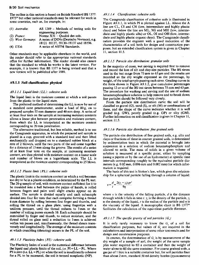
The Casagrande classification of cohesive soils is illustrated inFigure A9.1.1, in which PI is plotted against LL. Above the Aline are CL, CI and CH (low, intermediate and highly plasticclays) and below the line are ML, MI and MH (low, interme-diate and highly plastic silts) or OL, OI and OH (low, interme-diate and highly plastic organic clays). The Casagrande classifi-cation provides the engineer with a good indication of thecharacteristics of a soil both for design and construction pur-poses, but an extended classification system is given in Chapter11, section 11.5.
A9.L1.5 Particle size distribution: granular soils
In the majority of cases, wet sieving is required first to removeand record the loss of silt and clay-size particles. The BS sievesused in the test range from 75 mm to 63 um and the results arerecorded as the dry weight expressed as the percentage, byweight, of the total sample passing each sieve. Grading curves inthe form shown in Figure A9.1.2, give cumulative percentagespassing 12 or so of the BS test sieves between 75 mm and 63 um.The procedure for washing and sieving and the use of sodiumhexametaphosphate solution to help remove and to break downfine particles should be followed very closely.
From the particle size distribution curve the soil will beclassified as gravel (G), sand (S), or silt (M) or combinations ofthese, and the shape of the curve indicates whether it is wellgraded (e.g. GW), poorly graded (e.g. GP) or silty (GM).Further information on soil classification is given in Chapter 11,section 11.5.
A9.1.1.6 Particle size distribution: fine grained soils
The particle size distribution of fine grained soils, e.g. silts andclays or fractions of these in coarser grained soils, is determinedby sedimentation tests in which the material is brought intosuspension in a solution of sodium hexametaphosphate andallowed to settle. The mass of solids in a given volume ofsolution is measured at a specific point, either by sampling(using a pipette or by the use of an hydrometer) at specific timeintervals corresponding roughly to the equivalent particle dia-meters (e.g. 0.02 mm, 0.006 mm and 0.002 mm) for which infor-mation is required.
The basis of this test is Stokes's law, which gives the relation-ship for a spherical particle falling through a column of liquid:
_^_2(ys-y,)gr2
v"- 9«
where v is the velocity of the falling particle, d is the distancethrough which it falls in time /, ys is the density of the particle, y,is the density of the liquid, r is the radius of the particle and rj isthe viscosity of the liquid. A monographic chart in BS 137759
facilitates the calculation of the equivalent particle diameter.
A9.1.L7 The specific gravity of soil particles (GJ
It is only rarely necessary to know the Gs of a soil forclassification purposes, but values of G5 are required in thecalculations and interpretation of some other test results and fordesign and construction purposes.
In essence, the determination of Gs is by measurement of thedry weight of a sample of soil, the weight of the same sampleplus water required to fill a container and then the weight ofwater alone to fill the same container. For coarse grained soils, agas jar of 1 litre is a suitable container but, for soil particles finerthan about 2 mm, standard 50 ml density bottles (pycnometers)
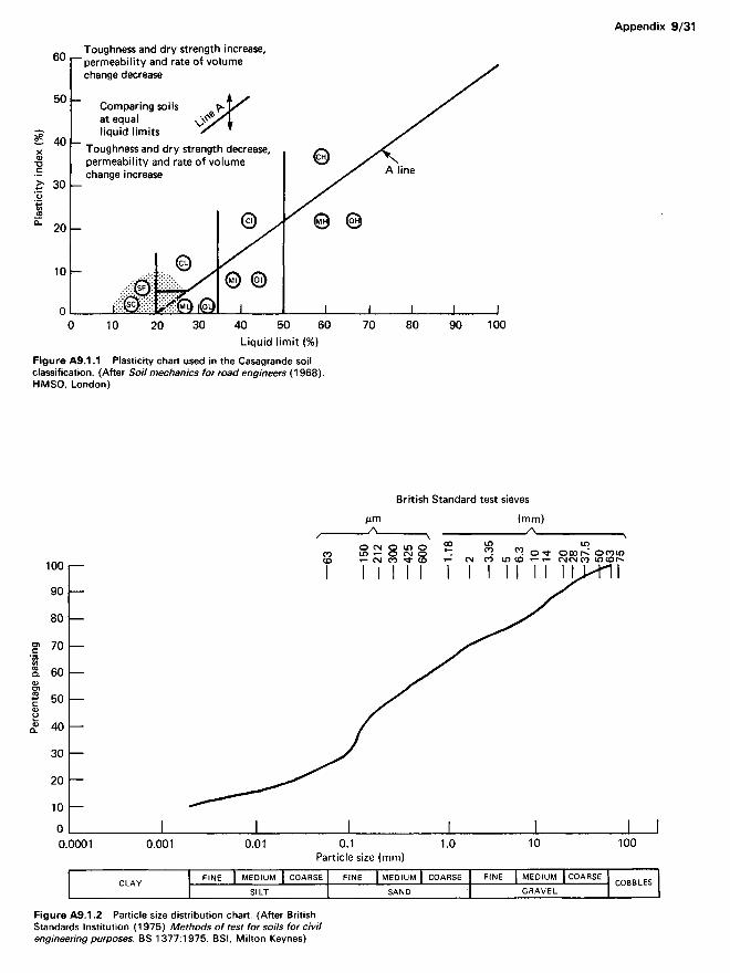
Figure A9.1.2 Particle size distribution chart. (After BritishStandards Institution (1975) Methods of test for soils for civilengineering purposes. BS 1377:1975. BSI, Milton Keynes)
CLAY FINE MEDIUMSILT
COARSE FINE MEDIUMSAND
COARSE FINE MEDIUMGRAVEL
COARSE COBBLES
British Standard test sieves
Liquid limit (%)Figure A9.1.1 Plasticity chart used in the Casagrande soilclassification. (After So/7 mechanics for road engineers (1968).HMSO, London)
Toughness and dry strength increase,permeability and rate of volumechange decrease
Comparing soilsat equalliquid limits
Toughness and dry strength decrease,permeability and rate of volumechange increase A line
Particle size (mm)
Plas
ticity
inde
x (%
)Pe
rcent
age p
assin
g
are often used. In either case, care is required to exclude air fromthe samples, involving the use of air-free distilled water in thetests on fine grained soils.
A9.1.2 Soil classification: chemical
A9.1.2.1 Organic matter content
Organic content is expressed as the percentage by mass oforganic matter present in the soil.
The organic matter in a sample of soil dried in an ovenbetween 105 and 110° C is oxidized in a 500ml conical flask bythe addition of 10ml potassium dichromate solution and 20mlconcentrated sulphuric acid. The sample of soil should weighbetween 0.2 g for peaty soil and up to 5 g for a soil with loworganic content. Processes of titration determine the volume ofpotassium dichromate used to oxidize the organic matter and,hence, the organic content. Soils containing sulphides or chlor-ides require some special treatment.
A9.1.2.2 Total sulphate content of soil
This is determined as the percentage mass of sulphate (as SO3)present in the soil sample, represented by the material passing,or which can be crushed to pass, the 2 mm sieve. The sample fortest is then pulverized until it passes the 425 um sieve. Stones,other than gypsum, may be assumed to contain no sulphate.
The test procedure involves treatment of the sample withhydrochloric acid and ammonia to form an acid extract, whichis boiled and barium chloride solution added, to form a precipi-tate of barium sulphate. The mass of the precipitate formed isdetermined by filtration and ignition, and gives a measure of theSO3 present in the sample.
A9.1.2.3 Sulphate content of groundwater
To determine the percentage of sulphate (as SO3) present in thesoil water or groundwater requires the extraction of water froma soil sample by means of a centrifuge or other means or thecollection of a sample of groundwater. The extract or sample ispassed through an ion exchange column comprising a stronglyacidic cationic exchange resin; the sulphate content of the soilwater extract or the groundwater can be separately determinedby titration of a standardized sodium hydroxide solutionagainst the resultant solution. In both cases, the SO3 content isexpressed in grams per litre.
A9.1.2.4 pH value
The pH value indicates the acidity or alkalinity of a soil, withvalues above 7 indicating alkalinity and values below 7 increas-ing acidity. The pH of groundwater can be determined in similarways, using either an electrometric or a calorimetric method.The former method is most usual.
For the electrometric method, standard pH meter electrodesare placed in suspension of the soil sample in water and thereadings obtained record the pH value. Buffer solutions are usedto calibrate the pH meter.
A9.1.2.5 Additional chemical tests for contaminants
Although outside the scope of this chapter, the increasingproportion of construction on sites previously used for a rangeof industrial purposes has led to the need for additional and,often, more extensive soil testing. The problems involved arereferred to in Chapter 11 and attention is drawn to the biblio-graphy in that chapter relating to contaminated sites.
On contaminated sites, the presence of methane and of avariety of potentially dangerous or toxic chemicals needs to beconsidered from the point of view of safety of workmen duringconstruction. Corrosive materials that could affect the durabil-ity of materials in a new construction should also be identifiedand special precautions taken in the design of the new construc-tion to limit such damage. Common examples of aggressivematerials are chlorides, sulphates and electrolytic, chemical orbacteriological agencies of various types.
Information and experience on the subject of contaminatedsites is increasing rapidly and the reader with a special interest isadvised to consult, for example, the Building Research Estab-lishment for the most up-to-date information.
A9.1.3 Soil compaction
A9.1.3.1 Dry density: moisture content relationships
Laboratory compaction tests determine the mass of dry soil percubic metre obtained when the soil is compacted in a specifiedmanner at a specific moisture content. Repetition of the testover a range of moisture contents provides a compaction curveindicating the optimum moisture content and maximum drydensity obtainable for the compactive effort applied.
The original 'Proctor' test simulated the compactive effort ofconstruction plant in the 1930s. Later, the modified AmericanSociety of State Highway Officials (AASHO) test was developedto model heavier construction plant and, in the UK, a vibratorytest was introduced in 1967 to simulate the effect of heavycompaction by vibrating rollers and plates. A comparison of theBritish and American tests is shown in Table A9.1.1.
In each test, soil of predetermined moisture content is placedin a specified number of layers into a cylindrical mould, andeach layer is compacted by a specified number of blows with astandard rammer or, in the case of the vibration method, for aperiod of 60 s. A typical compaction curve obtained from aseries of tests is shown in Figure A9.1.3.
While the modified AASHO test or its BS equivalent issuitable for fine grained as well as coarse grained granular soilsup to 20 mm, the BS vibratory method is applicable to soils upto 37.5 mm and is preferred for soils such as clean gravels orrocks and for uniformly graded and coarse sands.
A9.1.3.2 Measurement of dry density
Reference is made in Chapter 11 of the sand replacement testmethod for the measurement of dry density of compacted soil ITIsitu, and to nuclear and other tests available. For fine grainedsoils it is sometimes more convenient to cut cores, trim the soilcore to the cutter size (usually 100mm diameter by 130mmlong) and to determine the weight of dry soil within thosedimensions.
Table A9.1.1. Comparison of standard American and Britishcompaction tests
Test
ProctorModifiedAASHOBS 1377
test 12test 13test 14
(vibratory)
No. oflayers
3
5
353
Blows perlayer
25
27
2527
Weight ofhammer(kg)
2.5
4.55
2.54.5
60 s with 300-400 Ndown force
Height ofdrop(mm)
305
457
300450
Volumeof mould(CC)
944
944
10001000c.2300

Moisture content (%)
Figure A9.1.3 Typical compaction curve and the terms used.(After British Standards Institution (1975) Methods of test for soilsfor civil engineering purposes. BS 1377:1975. BSI, Milton Keynes)
An alternative laboratory method appropriate to lumps ofsoil, preferably approximately cubical or cylindrical, involvescoating them with paraffin wax and subsequent determinationof the soil volume by weighing the sample immersed in water orby a water displacement method.
A9.1.4 Strength tests
A9.L4.1 Californian bearing ratio (CBR)
The Californian bearing ratio (CBR) test was developed in 1938to evaluate Californian highway subgrade strengths and becamethe basis for the design of road and airfield pavements through-out the world. It is used both in situ and on prepared samples inthe laboratory, but is limited to materials of particle sizes up to amaximum of 20 mm.
The test determines the relationship between force and pene-tration when a cylindrical plunger 1935 mm2 in cross-section ispressed into soil at a given rate of 1 mm/min. For any givenpenetration, the ratio is expressed as a percentage of a standardforce derived for crushed stone.
For CBR tests in the laboratory, the soil specimen is preparedat a predetermined moisture content and is compacted into acylindrical mould 152mm in diameter and 127mm high eitherby continuous tamping, compression in three equal layers ordynamic compaction in layers, using either the rammers or thevibrating hammer used in the compaction tests. In all cases, themass of soil poured into the mould is calculated as that requiredto provide the chosen dry density or air voids percentage oncompletion of compaction. These usually correspond to theoptimum, determined from compaction tests, or are the valuesmeasured on the soil in situ.
Results of the test are plotted as shown in Figure A9.1.4. TheCBR is calculated at penetrations of 2.5 and 5 mm, and thehigher value taken. The standard forces corresponding to 100%CBR at these two penetrations are 13.24 and 19.96kN respec-tively. The force-penetration curve is normally convex upwards,but curves beginning as concave upwards require correction byshifting the zero on the penetration axis.
A9.1.4.2 Other plate bearing tests
A variety of plate bearing tests has been used in site investiga-tions and are mentioned in Chapter 11. However, for airfield
Penetration of plunger (mm)
Figure A9.1.4 Typical California bearing ratio test results. (AfterBritish Standards Institution (1975) Methods of test for soils forcivil engineering purposes. BS 1377:1975. BSI, Milton Keynes)
A9.1.4.3 Determination of shear strength
The vane test For in situ measurement of shear strength, a vaneof cruciform section 50 or 75 mm in diameter and of lengthequal to twice the diameter is lowered into a borehole andpushed, without twisting, to a depth not less than 3 times theborehole diameter into the undisturbed soil. A torque headfitted to the top of the vane rods turns the vane at a rate between10 and 20°/s until the soil is sheared.
For vanes with height twice the diameter, the vane shearstrength S is given by:
s-&W
where M is the torque to shear the soil in newton metres and D isthe measured width of the vane in millimetres.
Direct shear test In this test, a soil sample is cut and trimmedcarefully to fit closely into a metal box, either circular or squarein plan, which is constructed to allow displacement along itshorizontal midplane. The upper surface of the sample is con-fined by a normal load and a shear load is applied to the lowerhalf of the box until the soil shears across the midplane.
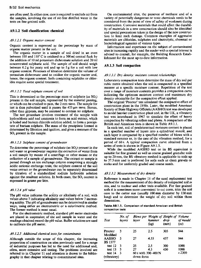
The triaxial test The triaxial cell (Figure A9.1.5) provides themeans of applying horizontal pressures to a cylindrical specimenby means of lateral hydraulic pressure in the cell chambersimultaneously with a vertical load applied by a ram. The
Air voids lines (G5 = 2.65)
Maximum drydensity
Compaction curve
pavements and use in Westergaard's analysis of strains anddeflections in concrete slabs, a test developed in the US60 is usedto measure the 'modulus of subgrade reaction'. The plate isusually 750mm in diameter and a linear plot of settlementagainst pressure applied gives a curve which is convex upwards.The modulus of subgrade reaction k is calculated as:
k= pi'1.21 g/mm2/mm
where p is the pressure required to cause settlement of 1.27 mm.
Standard resultfor crushed stone
Test 1No initial correctionrequired
Test 2Initial correction required
Dry
dens
ity o
f soil
(Mg/
m3)
Optim
um m
oistur
eco
nten
t
Force
on
plung
er (k
l\l)
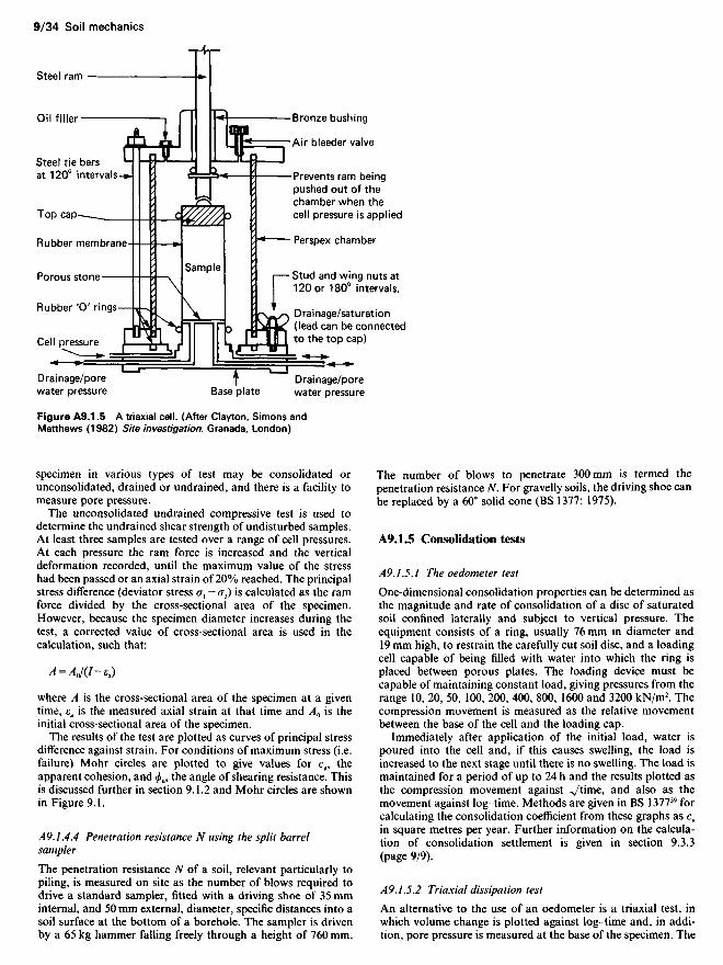
Figure A9.1.5 A triaxial cell. (After Clayton, Simons andMatthews (1982) Site investigation. Granada, London)
specimen in various types of test may be consolidated orunconsolidated, drained or undrained, and there is a facility tomeasure pore pressure.
The unconsolidated undrained compressive test is used todetermine the undrained shear strength of undisturbed samples.At least three samples are tested over a range of cell pressures.At each pressure the ram force is increased and the verticaldeformation recorded, until the maximum value of the stresshad been passed or an axial strain of 20% reached. The principalstress difference (deviator stress cr, — <73) is calculated as the ramforce divided by the cross-sectional area of the specimen.However, because the specimen diameter increases during thetest, a corrected value of cross-sectional area is used in thecalculation, such that:
A = AQ/(I-e.d)
where A is the cross-sectional area of the specimen at a giventime, £a is the measured axial strain at that time and A0 is theinitial cross-sectional area of the specimen.
The results of the test are plotted as curves of principal stressdifference against strain. For conditions of maximum stress (i.e.failure) Mohr circles are plotted to give values for cu, theapparent cohesion, and <£u, the angle of shearing resistance. Thisis discussed further in section 9.1.2 and Mohr circles are shownin Figure 9.1.
A9.1.4.4 Penetration resistance N using the split barrelsampler
The penetration resistance TV of a soil, relevant particularly topiling, is measured on site as the number of blows required todrive a standard sampler, fitted with a driving shoe of 35 mminternal, and 50 mm external, diameter, specific distances into asoil surface at the bottom of a borehole. The sampler is drivenby a 65 kg hammer falling freely through a height of 760 mm.
The number of blows to penetrate 300mm is termed thepenetration resistance TV. For gravelly soils, the driving shoe canbe replaced by a 60° solid cone (BS 1377: 1975).
A9.1.5 Consolidation tests
A9.1.5.1 The oedometer test
One-dimensional consolidation properties can be determined asthe magnitude and rate of consolidation of a disc of saturatedsoil confined laterally and subject to vertical pressure. Theequipment consists of a ring, usually 76 mm in diameter and19 mm high, to restrain the carefully cut soil disc, and a loadingcell capable of being filled with water into which the ring isplaced between porous plates. The loading device must becapable of maintaining constant load, giving pressures from therange 10, 20, 50, 100, 200, 400, 800, 1600 and 3200 kN/m2. Thecompression movement is measured as the relative movementbetween the base of the cell and the loading cap.
Immediately after application of the initial load, water ispoured into the cell and, if this causes swelling, the load isincreased to the next stage until there is no swelling. The load ismaintained for a period of up to 24 h and the results plotted asthe compression movement against *Jtime, and also as themovement against log-time. Methods are given in BS 137759 forcalculating the consolidation coefficient from these graphs as cy
in square metres per year. Further information on the calcula-tion of consolidation settlement is given in section 9.3.3(page 9/9).
A9.1.5.2 Triaxial dissipation test
An alternative to the use of an oedometer is a triaxial test, inwhich volume change is plotted against log-time and, in addi-tion, pore pressure is measured at the base of the specimen. The
Steel ram
Oil filler
Steel tie barsat 120° intervals
Top cap
Rubber membrane
Porous stone
Rubber 'O' rings
Cell pressure
Drainage/porewater pressure Base plate
Sample
Bronze bushing
Air bleeder valve
Prevents ram beingpushed out of thechamber when thecell pressure is applied
Perspex chamber
Stud and wing nuts at120 or 180° intervals.
Drainage/saturation(lead can be connectedto the top cap)
Drainage/porewater pressure
compressibility measured as a result of triaxial dissipation isgreater than that determined in the oedometer test.
Appendix 9.2 Pile capacities
Piles are used to transfer foundation loads to a deeper stratumwhen the surface soils are too weak or too compressible to carrythe load without excessive settlement. Details of pile types andtheir design and use are given in Chapter 17. The reader'sattention is drawn to the references in Chapter 17 for furtherinformation, particularly to BS 800413, Tomlinson61-62 and toseries of CIRIA/PSA piling guides.63
In this appendix, methods are given for estimating the carry-ing capacity of piles in various types of soil conditions.
A9.2.1 Groups of piles
A piled foundation generally consists of a group of several piles,the behaviour of which should be considered as an entity.
The piled group will consist of either point-bearing pileswhich transfer their load to a hard stratum of soil on which theirpoints bear (e.g. piles to rock) or friction piles which transfertheir load mainly by friction on the sides of the piles to a firmstratum into which they penetrate. Friction piles into a firm claystratum will usually penetrate about 20 to 30 times the pilediameter into the clay. Piles driven through soft material intocompact sand or gravel will usually penetrate about 5 times thediameter and will be partly point-bearing and partly frictional.
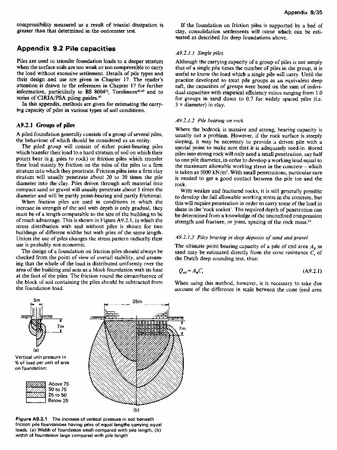
When friction piles are used in conditions in which theincrease in strength of the soil with depth is only gradual, theymust be of a length comparable to the size of the building to beof much advantage. This is shown in Figure A9.2.1, in which thestress distribution with and without piles is shown for twobuildings of different widths but with piles of the same length.Unless the use of piles changes the stress pattern radically theiruse is probably not economic.
The design of a foundation on friction piles should always bechecked from the point of view of overall stability, and assum-ing that the whole of the load is distributed uniformly over thearea of the building and acts as a block foundation with its baseat the foot of the piles. The friction round the circumference ofthe block of soil containing the piles should be subtracted fromthe foundation load.
If the foundation on friction piles is supported by a bed ofclay, consolidation settlements will occur which can be esti-mated as described for deep foundations above.
A9.2.1.1 Single piles
Although the carrying capacity of a group of piles is not simplythat of a single pile times the number of piles in the group, it isuseful to know the load which a single pile will carry. Until thepractice developed to treat pile groups as an equivalent deepraft, the capacities of groups were based on the sum of indivi-dual capacities with empirical efficiency ratios ranging from 1.0for groups in sand down to 0.7 for widely spaced piles (i.e.3 x diameter) in clay;
A9.2.L2 Pile bearing on rock
Where the bedrock is massive and strong, bearing capacity isusually not a problem. However, if the rock surface is steeplysloping, it may be necessary to provide a driven pile with aspecial point to make sure that it is adequately toed-in. Boredpiles into strong rock will only need a small penetration, say halfto one pile diameter, in order to develop a working load equal tothe maximum allowable working stress in the concrete - whichis taken as 5000 kN/m2. With small penetrations, particular careis needed to get a good contact between the pile toe and therock.
With weaker and fractured rocks, it is still generally possibleto develop the full allowable working stress in the concrete, butthis will require penetration in order to carry some of the load inshear in the 'rock socket'. The required depth of penetration canbe determined from a knowledge of the unconfined compressionstrength and fracture, or joint, spacing of the rock mass.62
A9.2.J.3 Piles bearing in deep deposits of sand and gravel
The ultimate point bearing capacity of a pile of end area AB insand may be estimated directly from the cone resistance Cr ofthe Dutch deep sounding test, thus:
CuB = ̂ r (A9.2.1)
When using this method, however, it is necessary to take dueaccount of the difference in scale between the cone (end area
Vertical unit pressure in% of load per unit of areaon foundation:
Above 7550 to 7525 to 50Below 25
Figure A9.2.1 The increase of vertical pressure in soil beneathfriction pile foundations having piles of equal lengths carrying equalloads, (a) Width of foundation small compared with pile length; (b)width of foundation large compared with pile length

10cm2) and the pile by ensuring that the pile penetrates thebearing layer some 4 to 6 or more diameters for piles of less than450 mm diameter. For larger piles, greater penetration ratios arenecessary (see Tomlinson,62 for further information on thisproblem). The bearing capacity can also be determined fromBerezantsev's64 curves. However, results of theoretical calcula-tions may be unreliable, and past experience is a better guide.
In deeply embedded piles it is also necessary to take accountof the side friction, a factor which depends upon the horizontalearth pressure coefficient K^ the overburden pressure y'D andthe angle of shearing resistance 6 between the ground and thepile; thus the ultimate shaft resistance is given by:
gus = AsKs(y'D tan <5) (A9.2.2)
where As is the shaft area and ^s and y'D refer to average valuesof Ks and y'D.
The horizontal coefficient K^ depends not only upon the relativedensity and stress history of the deposit, but also upon themethod of forming the pile. In bored piles it can be as low as0.7 x at-rest earth pressure coefficient, rising to twice thiscoefficient for large displacement. The value of 6 depends uponthe value of <£ and the pile material; <5/<£ varies from 0.50 to 0.80for steel and precast concrete respectively (see Tomlinson62 for afull discussion on the question of shaft resistance).
The frictional resistance of the ground for driven piles can alsobe determined by use of the friction sleeve adaptation to theDutch deep-sounding apparatus. This gives the term Ksy'D, tan 6throughout the depth of the deposit directly (see Chapter 11).
The ultimate bearing capacity of the pile is given by the sumof Equations (A9.2.1) and (A9.2.2):
Qu = Q,B +Qu, (A9.2.3)
Frequently, pile bearing capacities have to be based on standardpenetration test data. Meyerhof65 has proposed the followingempirical relationships for the components Q11 and Qus:
fi.-^107)4JV+^4(107) (A924)
where Qu is in kilonewtons and AB and As are in square metresand N is the average N value along the pile shaft.
An upper limit of 60 kN/m2 is suggested for the shaft resistance.It is suggested that the point bearing capacity term in
equation (A9.2.4) might be written as follows, to take accountof the actual soil type into which the pile is driven:
QU* = AB(W1)KN (A9.2.5)
When it is possible to carry out a loading test on a full-scale pilethis should be done, the test being carried to failure, i.e. untilsettlement continues under constant load.
The use of dynamic pile-driving formulae to calculate theultimate load is not to be recommended for two reasons,namely: (1) the information is obtained too late (i.e. at theconstruction stage instead of the design stage unless previousexpensive tests are carried out) in which case loading testsshould be included); and (2) a very wide range of answers can beobtained depending on the formula used and the choice ofconstants in the formula.
Dynamic pile-driving formulae have their uses, however, andrecords of set and energy should always be kept as they areguides to the variation in ultimate loads over a site on which oneor two loading tests have already been carried out. Engineers of
wide experience can also make estimates of the load-carryingcapacity from the results of a driving test, provided always thattheir experience was obtained with conditions similar to thoserelating to the test. The relation between the true ultimate loadand that given by the dynamic formula is empirical and shouldbe recognized as such in spite of the mathematical basis ofNewtonian impact mechanics on which such formulae appear tobe founded.
A9.2.1.4 Piles bearing in clay
A pile bearing in clay receives support from the adhesion alongthe shaft and from the resistance at its base, the relativecontribution of these two components depending upon thestrength-depth profile of the clay, the ratio of the length todiameter of the pile and the manner of its installation, i.e.whether bored, driven preformed, or cast-in-place. Skempton66
has given the following expression for the bearing capacity of abored pile in London Clay:
Q = 9cuAb + acuAs (A9.2.6)
where a is an empirical factor which depends on the type of pile,the clay and its condition, and varies between 0.3 and 0.6 for abored pile in London Clay, with a mean value of 0.45 for a well-constructed pile in typical unweathered clay, and cu is theaverage shear strength along the pile shaft, with an upper limitof 100 kN/m2 for the average ultimate skin friction resistance.
The bearing capacity of a bored pile can be increased greatly byconstructing an enlarged base (belling or under-reaming). Thevalue of a for under-reamed piles should not exceed 0.3.
The shear strength of the clay in commercial practice isdetermined on 38mm specimens cut from 100-mm drivensamples, and experience over the last decade has shown that,owing to the fissured nature of London Clay, this practiceresults in considerably higher strengths being used in the assess-ment of end bearing capacity than obtain in situ (see Whitakerand Cooke67 and also Burland, Butler and Dunican68). It isnecessary therefore to allow for this factor by introducing anempirical coefficient a> related to the base diameter B of the pile,thus:
Q = 9cQcAB + acuA^ (A9.2.7)
where o> = 0.8 for B< 1 m and 0.75 for B> 1 m, and acu has anapproximate limit of 100 kN/m2.
In the event of the strength being determined on larger speci-mens or from in situ piston tests, upward modification in thevalue of co is necessary. Load factors used in the design rangefrom 2 for straight-shafted piles to 2.5 for base diameter lessthan 2m as these values will generally restrict the short-termsettlement of the single pile to less than 10mm. With diameterslarger than 2 m the working load should be checked by calculat-ing the settlement using the curves relating QJQ to settlementshown in Figure A9.2.2.
The range of a values discussed above is based on experienceof London Clay. In dealing with other overconsolidated clays(e.g. the Lias, Kimmeridge and Oxford Clays and in weatheredmarls) some caution is needed in assigning a values, and whereprevious experience is not available, loading tests designed toestablish a values should be undertaken.
Piles driven into soft sensitive clays result in loss of strength inthe clay in contact with the pile, and thus test loading should bedelayed for as long as possible after driving, preferably at least amonth, to allow thixotropic strength to be regained.

Settlement of pile head (mm)Figure A9.2.2 QJQ against settlement in loading tests, showingthe mean curves for piles with and without enlarged bases. (AfterWhitaker and Cooke (1966) 'An investigation of the shaft and baseresistance of large bored piles in London Clay', Proceedings,conference on large bored piles. Institution of Civil Engineers,London)
Piles driven into stiff clay cause severe disturbance andfracturing to the clay and experience has shown that theeffective cohesion can be extremely erratic, even on the same site(Tomlinson62). The lower limit of the adhesion factor, Tomlin-son suggests, ranges from about 1.0 for soft clays to 0.2 for stiffand very stiff clays. When piles are driven to deep penetrationsinto stiff clays, the adhesion factor is influenced by the effectiveoverburden pressure at any point in the pile shaft.62
Loading tests should be carried out whenever possible.Piles driven into ground which is subject to consolidation
from loading, or which is still settling under prior loading, aresubject to downdrag forces (negative skin friction) which placean additional load on the toe. These forces can be severe andshould be taken into account in the design and test loading.Negative skin friction can also occur, when driving pilesthrough soft sensitive clays to bear on a harder stratum, owingto dissipation of the pore pressures induced by driving. Negativeskin friction can be reduced by slicking the pile with theappropriate grade of bitumen. Johannessen and Bjerrum69
recommend the evaluation of downdrag using effective stresses.
Appendix 9.3 Ground improvement
There are numerous cases in which the properties of naturallyoccurring soil or fill material can be improved or changed tohelp solve engineering problems arising either in temporary orpermanent works. The methods of ground improvement cover awide range of techniques - often referred to as geotechnicalprocesses - and include compaction, moisture control, stabiliza-
tion, grouting and reinforcement. Reference should also bemade to the use of geotextiles for reinforcement, separation andfiltration in the ground and of mild steel reinforcement strips toproduce reinforced earth structures with increased shear proper-ties in embankments and fills. Various other processes have beendeveloped and the whole subject of ground improvement de-serves special study starting, for example, with Chapters 29 to38 of the Ground engineer's reference book.™
This appendix lists and gives a brief description of the mainground improvement methods.
A9.3.1 Drainage and water lowering
Drainage systems to control groundwater in engineering worksmay include seepage reduction measures, such as imperviousbarriers of sheet piles, membranes or grouts, together withdrains incorporating a filtering material, sometimes envelopedwithin a plastic fabric filter. In sands and gravels, water-lowering systems can be used to allow an excavation to becarried out in the dry or to reduce the water pressure on the sidesand base of the excavation.
A9.3.L1 Site investigation
A thorough site investigation to establish the hydrogeologicalcharacteristics of a site is an essential preliminary to the designof any groundwater lowering project. This is discussed further inChapter 11.
9.3.1.2 Permeability and filters
The permeability (transmissibility divided by the depth of theaquifier) can be determined by pumping from a large-diameterwell while monitoring the drawdown in a number of adjacentobservation wells. The shape of the drawdown-time curve ismatched to type curves derived theoretically, and the transmissi-bility and storage coefficients so deduced. A wide range ofavailable type curves enables varying aquifiers and hydrologicboundary conditions to be considered. Alternatively, for a fullypenetrating well into an unconfined aquifier, permeability canbe estimated from the equilibrium drawdown-distance curve,using Equation (A9.3.1). This latter method, which is the olderof the two described, requires the establishment of equilibriumconditions, which may take many days; in contrast the time-variant method can be applied within a matter of hours aftercommencement of pumping.
Pumping tests give the most reliable value for k but an orderof permeability can be obtained from grading curves (seeLoudon71). Undisturbed samples of fine sands are essential inorder to see if the material is laminated - a fact which naturallycan have a marked effect on the horizontal permeability.
Grading curves are also used to choose suitable sand as afilter medium using Terzaghi's empirical rule which states thatthe grading curve for the filter material should be the sameshape as that for the material to be filtered, and:
P1, (filter) A5 (filter)O85(SOiI) -4lo:>- D15(SOiI)
where D15 and D85 are the grain sizes corresponding to those atwhich 15% and 85% pass on the grading curves.
A9.3.1.3 Pumping capacity
The quantity of water to be pumped from a fully penetratingwell into an unconfined aquifier can be calculated from theequation:
Piles withenlarged bases
Piles withoutenlarged bases
Appli
ed lo
ad
Q 3Ul
timat
e loa
d ~
Q

. xk(H2-h2) . ...Q = ̂ Ri^T (m/s) (A9.3.1)
where k is the permeability in metres per second, H is the depthfrom normal water level to the impermeable stratum in metres, his the depth from lowered water level to the impermeablestratum in metres, R is the radius of cone of depression in metresand A is the radius of circle of area equal to area surrounded bywells in metres.
R can be obtained from the empirical relation
R = 30(H- /OV* (m) (A9.3.2)
The number of wells required can be obtained from the empiri-cal relationship
g = 3.63 x 10-V0A0H** (m3/s) (A9.3.3)
where r0 is the radius of a well in metres. H0 is the water leveloutside a well in metres, k the permeability in metres per secondand n is the number of wells required.
A9.3.1.4 Well points, suction wells and deep wells
Three systems of water lowering are in common use and eachhas certain advantages and disadvantages.
Well points When the lowering of the water level required is4.5m or less, a well point system can be used. If the systemoperates very efficiently, greater lowering can be obtained, butthis should not be assumed at the planning stage.
A well point is a metal tube about 50 mm_diameter carrying agauze filter about 1 m long at its lower end. New types of wellpoints are now on the market with slotted plastic outer coveringand metal centre tubes. The well points are jetted into theground at intervals of 1 or 2 m and then connected to a headermain through which the water is extracted by a well-point pumpfor exhausting the main and well points, and a centrifugal pumpto remove the water.
Well points are cheap to install and, for a long progressiveexcavation such as a pipe or sewer trench, they are usually themost economical system. If greater lowering than 4.5m isrequired, a two-stage system can be used.
A special trenching machine is now available for laying ahorizontal porous pipe of 100mm diameter at depths down to5m below ground level. A pipe up to a maximum length ofabout 230 m can be installed, and for continuous trench workthe pipes are overlapped by about 4.5 m,
Shallow wells These are, in principle, the same as well pointsbut the wells are bored into the ground. The wells are usuallyabout 600 mm diameter with a 300 mm filter tube and a 75 to100mm diameter suction pipe. The space outside the 300mmtube is filled with a gravel filter as the boring tube is withdrawn.Because of their greater diameter, the wells usually can bespaced about 10 to 15m apart, and since there are many fewerconnections than in a well-point system, the efficiency is greater.The wells are connected to a ring main and a well-point pump.Alternatively ordinary suction-lift pumps can be installed indi-vidually in the wells for small excavations.
The cost of pumping is much the same for a given lowering ofthe water level from either a well-point or a shallow well system,but the cost of installation of the shallow wells is higher. Theshallow well installation is often to be preferred for an excava-tion of rectangular shape (as opposed to a long trench) wherepumping must continue for many months, and in fine sandswhere a graded filter is necessary or in laminated soils where adefinite vertical connection between the aquifers is required.
As in the case of well-points, two-stage systems can be usedfor a lowering of more than 4.5 m but, in general, deep wells willprove cheaper.
Deep wells With the deep-well system lowering of the waterlevel can be achieved in one stage. This is because the pumps areplaced at the bottom of the wells and deliver the water againstpressure; there is no suction lift. The pumps used are electricallydriven submersible pumps.
The well cannot be less than 450 mm diameter, which allows a75mm thickness of filter gravel, and if a two-stage filter isdesired the well will be 600mm diameter. For this reason thecapacity of the wells is much greater than in the case of shallowwells and they can therefore be spaced further apart, in generalup to 30 m, but this will vary considerably on different installa-tions.
The cost of a deep-well system is high but it generally givessafe dry excavation and can often reduce the time of construc-tion considerably. For safety, two independent sources ofelectric power must be provided for the pumps, since once theyhave started pumping it might be disastrous if they failed.
A9.3.L5 Vacuum drainage
In soils of low permeability, such as coarse silts, drainage cansometimes be effected by sealing the wells or well points andexhausting the air from them. The pressure of the atmospherethen acts as a surcharge on the soil causing it to consolidate, andwater is squeezed out of the soil into the filters of the wells. Theamount of water removed is very small but the increase instrength of the silt is marked, and excavation is greatly facili-tated.
A9.3.1.6 Electro-osmosis
Electro-osmosis is a further drainage process which can be usedin silts. It is based on the principle that if a direct electric currentis passed through the soil a flow of water takes place from anodeto cathode. The cathode is made into a well and the water whichreaches it is pumped out. The amount of water removed is small.The success of the method depends, as with the vacuum method,on the fact that the flow of water is away from the excavation,the free water surface is lowered and the water which remains inthe soil above this surface is in tension, and that the capillarytensions add greatly to the strength of silt. To some extent alsothe water content of the soil is reduced, thus resulting in anincreased strength. Electro-osmosis is an expensive process andshould only be considered if more normal methods of construc-tion are inapplicable. In many silts the vacuum method ofdrainage is probably nearly as effective and much cheaper.
A9.3.1.7 Settlements caused by water lowering
When the water level is lowered the effective weight of the soilbetween the original and the lowered water levels is increasedbecause the buoyancy effect has been removed. Where the soilconcerned is sand and gravel any settlements due to this increasein weight are normally small, but where silt, clay or peat occursin the zone referred to, settlement will occur with time owing tothe consolidation of this material under its own increasedweight. Advantage is taken of this in the methods given insection A9.3.2 to accelerate settlement.
Before installing a groundwater lowering system it is essen-tial, therefore, to consider what effect such settlements may haveon structures within the zone of influence. Important structureswill probably be founded below the compressible material,either directly or on piles, and will be unaffected. For structures

founded on the compressible strata, it is necessary to calculatethe probable settlement and to estimate what damage, if any, tothe structure would result.
In order to limit the radius of influence of a groundwaterlowering system, some of the pumped water can be 'recharged'or fed back into the aquifer by means of infiltration wells sitedclose to the structure below which it is desired to limit thepotential settlement.72
A9.3.2 Vertical drains to accelerate settlement
Vertical drains are used to accelerate the settlement of layers ofsoft clay or silt under applied loads. In many cases settlementcan be tolerated provided it occurs quickly, preferably duringthe construction period, e.g. road embankments on soft clay(Figure A9.3.1).
The rate at which a uniform thin clay layer consolidates isinversely proportional to the square of the drainage path, whichis either the thickness or half the thickness of the layer depend-ing on the drainage conditions. The principle of this method isto provide vertical drains in the clay. The drainage path is thenreduced to half the spacing of the drains. When the load (e.g. afill) is applied, the settlements take place quickly in, say, a fewmonths instead of many months or even years. It is important tonote that vertical drains do not reduce the amount of settlement.
Vertical drains are particularly effective in deposits where thehorizontal permeability is high compared with its vertical per-meability. However, care must be taken to avoid local reductionof horizontal permeability by the process of installation of thedrain. In deposits of exceptionally high lateral permeability,vertical drains may not be necessary. It is important, therefore,to investigate the horizontal drainage characteristics with greatcare.73 .....
The consolidation of the clay under load increases itsstrength, a fact which can sometimes be made use of byconstruction, in stages, of a fill which would cause foundationfailure if placed in one operation.
A9.3.2.1 Vertical sand drains
Vertical sand drains usually have been formed by driving ahollow mandrel and filling the space formed by the forciblydisplaced soil with sand as the mandrel is withdrawn. Jettingand augering methods have also been used. The drains aregenerally between 0.15 and 0.5 m in diameter at between 2 and5 m centres and up to 30 m long, depending on conditions. Ahorizontal drainage blanket is required at ground level to linkthe vertical drains together before the fill is placed, unless the fillitself is permeable.
The disturbance of the foundation soil during the installationof vertical sand drains is an undesirable feature, particularly ifthe method of installation could cause remoulding of sensitiveclays. Various attempts have been made to develop thinnerdrains to reduce disturbance, such as the band drains describedin section A9.3.2.3.
A9.3.2.2 Prefabricated drains (sandwicks)
The original Kjellmann wick drain of treated cardboard hasbeen replaced by the use of fabric stocking filled pneumaticallywith sand or grooved plastic cores with nonwoven textile orgeotextile filter coverings. Several different designs of plasticdrains are available.
A9.3.2.3 Prefabricated band drains
An extension and, in many respects, an improvement on theprefabricated sandwicks are the band drains74 which consist of aflat core with internal drainage grooves surrounded by a filter
Figure A9.3.1 Typical vertical drain installation. (After Gambin(1987) 'Deep soil improvement', in: Bell (ed.) Ground engineer'sreference book (Figure 36.6). Butterworth Scientific, Guildford)
cover, hence the name 'band'. The mandrel used to place theseprefabricated bands may be circular, rectangular or of any otherconvenient section that reduces the disturbance of the surround-ing soil. The equivalent diameters of band drains lie between 5and 10mm with a typical spacing of 1.2 to 1.5m and amaximum length of 60 m (Figure A9.3.2).
The particular advantages of band drains are their simplicity,speed and cost of installation, together with minimum dis-turbance of the foundation soil.
Figure A9.3.2 Examples of cross-sections of plastic band drains.(After Gambin (1987) 'Deep soil improvement', in: Bell (ed.)Ground engineer's reference book (Figure 36.10). ButterworthScientific, Guildford)
A9.3.3 Exclusion of groundwater
Retaining systems excluding groundwater from a site, or froman area of a site, include sheet piled walls, in situ concretediaphragm walls and contiguous bored pile diaphragm walls.The use of compressed air to exclude water from undergroundworkings is another well-developed technique. Freezing andgrouting are further possibilities which have the added potentialadvantage of strengthening the ground locally.
Cross-sectionDrainageblanket
Drains
Compressiblesoil
Substratum
Plan view
Area of influence(Diameter, D)
DrainsF

A9.3.3.1 Sheet piling
The use of standard interlocking steel sheet piles is described inChapter 17 (section 17.3.2.5) in relation to the construction ofbasements. For all except shallow excavations, the interlockingpiles require support either by struts, shores or by the use ofground anchors.
A9.3.3.2 In situ concrete diaphragm walls
Reinforced concrete diaphragm walls can be constructed toconsiderable depths by placing concrete by tremie tube in anarrow trench supported by bentonite mud. The trench isexcavated in short panels, 2 to 7m in length, using specialcutters with circulating mud, or grabs and stationary mud.Junctions between panels are formed by means of steel tubesacting as end shutters. The mud displaced by the rising concreteis used in subsequent panels provided it is still in good con-dition.75 It is possible to construct such walls in all types ofground, though difficulties have been known to occur whenconcreting in very soft alluvium owing to displacement of theclay under the high head of liquid concrete. In very permeableground, significant mud losses may occur.
A9.3.3.3 Contiguous bored pile walls
Walls consisting of soldiers of bored piles can also be made withor without the use of mud depending upon the ability of theground to support itself. The spacing can be varied and in thecase of contiguous bored pile walls each is bored slightly into thecompleted adjacent pile while the concrete is still 'green'.
A9.3.3.4 Compressed air
The use of compressed air is well known as a constructionexpedient in underground work. It can be used in sands andgravels, silts and clays. The air pressure, acting on the surface ofthe soil in the excavation or, more correctly, on the watersurfaces in the voids of the soil, prevents the flow of waterthrough the soil and acts as a support. The air pressuretheoretically must be equal to the water pressure. In practice, apressure somewhat lower than the theoretical is often satisfac-tory. In gravels, the losses of air through the gravel may beserious and these can sometimes be cut down by injections ofclay suspensions into the gravel before commencing excavationin order to reduce the permeability.
The cost of compressed-air working can be high in areas ofsilt, fine sand and some clays which require considerable sup-port. However, it is often the most effective method for sub-aqueous tunnels in soft ground. Health hazards in compressed-air working, as in diving (Chapter 42), include the 'bends', andin the longer term, bone necrosis. The CIRIA medical code76
should be applied, using the appropriate decompression proced-ure and equipment. See also section 17.3.4.4.
A9.3.3.5 Ground freezing
Another temporary method of preventing the access of ground-water to excavations and of strengthening the soil locally is byfreezing the water. This is normally done by boring verticalholes into the ground, installing pipes in them and circulatingbrine or cryogenic liquids, cooled to below the freezing point ofwater, through the pipes. The freezing process is expensive andslow but once the water is frozen excavation can safely takeplace inside the frozen ring. The freezing must, of course, becontinued until the permanent work is completed. One of thedisadvantages of brine is that if a leak occurs in the pipes it willescape into the groundwater and it may then prove impossible
Figure A9.3.3 Scheme of ground freezing for support of anexcavation. (After Jeffberger (1987) 'Artificial freezing of theground for construction purposes', in: Bell (ed.) Ground engineer'sreference book. Butterworth Scientific, Guildford)
A9.3.4 Injection processes: grouting
It is sometimes possible to change the properties of the groundencountered by injecting materials of various sorts into thevoids of the soil. These changes include: (1) reduction inpermeability; (2) increase in strength; and (3) decrease in com-pressibility, or a combination of these. A major use is for fillingvoids in mine workings and karstic limestone.
Cases in which the reduction in permeability is importantinclude: (1) the formation of grouted cutoffs under dams; (2)grouting fissured rocks; (3) grouting sand and gravel to reduceair losses during construction work in compressed air; and (4)sealing gaps in sheet piling. The increase in strength is importantin underpinning problems and in support of excavation intunnelling. Injection processes can also be used to lift tanks andpavement slabs by hydraulic pressure, the grout later setting andsupporting the structure in the raised position.
A9.3.4.1 Materials that can be grouted
Grouts can be injected into the fissures in a rock. This isprobably one of the earliest applications of the process. Rockfilland rubble masonry can also be grouted. Cement grouts,containing sand or PF ash, are used in cases where the voids arefairly large.
Gravels and sands can be grouted successfully by a variety ofdifferent processes as described below, but clays and silts cannotbecause their voids are too small and their permeabilities too
to freeze it. To overcome this objection the Dehottay processwas introduced, in which liquid carbon dioxide is circulatedinstead of brine. More recently, liquid nitrogen has been used.The freezing process in general is applied to narrow, deepexcavations such as mineshafts, but cases are on record of its usein foundation work (Figure A9.3.3).
A9.3.3.6 Grouting
Injection processes using various types of grout are dealt withseparately in section A9.3.4 because of their wide applications inreducing permeability, increasing strength and reducing com-pressibility in soils and rocks.
COOLANTFeedReturn
Freeze pipeBrine pipe .
Excavation
Frozen wall
low. An exception to this is the use of the technique calledclaquage grouting, in which tongues of high-pressure groutpenetrate planes and zones of weakness within the soil body.
A9.3.4.2 Grouting materials
Grouts generally consist of suspensions, solutions or aeratedemulsions, the choice depending upon the nature of the workand the type of material to be grouted.
Suspensions The most commonly used grout is cement inwater but, because of its high sedimentation rate, it can berelatively unstable, depending on the water/cement ratio. Purecement grouts cannot be used for injecting sands or clays.Suspensions of cement with bentonite (e.g. in the proportions of4 or 5:1) are more stable, easier to pump and, generally,produce a better result than pure cement grouts. If the voids tobe filled are sufficiently large, sand is added to reduce shrinkageand cost. Another group of grouts comprises suspensions insolutions, e.g. in a solution of sodium silicate. An examplewould be a combined cement-bentonite-silicate grout.
Solutions There are several grouting processes in which solu-tions of chemicals based on sodium silicate are injected. Thechemical processes can be used down to the fine sand range.They divide into the two-solution and the single-solution pro-cesses.
In the two-solution processes (Joosten and Guttman pro-cesses) the first chemical injected is sodium silicate, and this isfollowed immediately by calcium chloride or some such salt.The reaction is almost immediate and for this reason thesolutions cannot penetrate far from the injection pipes which aretherefore spaced at about 600mm centres. The process givesconsiderable strength to the soil and also reduces the permea-bility to a very small fraction of its previous value.
In the single-solution processes, two chemicals are mixedbefore injection, possibly with a third chemical to delay thesetting action for some time. The injection pipes can thereforebe further apart. The processes reduce the permeability but donot give strengths comparable to the two-solution process.
In addition, a range of 'liquid' grouts is available, havingacrylic, formaldehyde, lignin and epoxide bases. These groutshave low viscosities and therefore considerable penetrationpower, and achieve comparatively high strengths. They are,however, more expensive than the common grouts.
Aerated emulsions These are cement- or organic-based groutsinto which a gas is emulsified. The properties of the resultingfoam depend upon the distribution of the gas bubbles which, inturn, depends upon the materials and method of preparation.The foams are not particularly strong and this type of grout isused mainly as a filling.
Other types of grout Cement grouts with a low water/cementratio (e.g. 0.4) are stable and pastelike in consistency. Forgrouting purposes, they can be made sufficiently fluid by the useof admixtures, such as plasticizers and swelling agents, or byvigorous stirring. 'Colgrout' is an example of the latter treat-ment and 'Prepakt' of the former. As the high potential strengthof these low water/cement ratio grouts is often unnecessary, alarge proportion of the cement can be replaced by pulverizedfuel ash (PFA).
Bituminous emulsions can also be used as grouts, e.g. toreduce the permeability of soils down to the fine sand range.
A9.3.4.3 Methods of grout injection
In nearly all grouting work the injections are made by drilling or
driving pipes into the ground and pumping the grout in underpressure through hoses attached to the pipes.
The spacing of the pipes varies widely with the process andthe conditions, from 600mm for the two-solution chemicalprocess in sand, to about 3 m for clay injections in alluvium, andup to 6 m or more for cement grouts in fissured rocks.
When filling fissures in rock with cement grout it is usual touse piston pumps which will give a pressure up to 7500 kN/m2.The same pumps can be used for clay injections with alluvialsands and gravels but the pressures must be controlled carefullyin relation to the depth and nature of the overburden to avoidundue lifting of the ground surface. If the limitation of groundheaving is important, suitable instrumentation for the monitor-ing of heave may be necessary. In the Joosten and Guttman two-solution chemical processes the amount of grout required to fillthe voids in the soil between injection pipes is pumped in withless regard to the pressure, subject to a maximum pressure ofabout 3000 kN/m2. Piston pumps are used.
For very simple grouting jobs, a grout pan may be used. Thecement grout is mixed in the pan by a paddle driven by hand orby a compressed air motor, an air pressure up to 750 kN/m2 isthen applied to the surface of the grout in the pan and this drivesthe grout through the hose into the injection pipe and so into theground. This suffers the limitation that the injection pressurescannot easily be varied to suit the ground conditions.
For more complex jobs, sleeve grouting is frequently usedusing a 'tube-a-manchettes'. The system comprises a PVC tubeof about 30 mm bore which is installed into a borehole of about90mm diameter and sealed into the ground with a relativelyweak bentonite-cement sleeve grout. The tube is equipped atshort intervals, normally 300 mm, with rubber sleeves coveringperforations. An injection device is located against selectedperforations in turn between upper and lower packers. Thegrout lifts the sleeve, fractures the sleeve grout and enters theground. With this device it is possible to return to any positionand regrout.
Grouting work in general is not simple and damage can becaused by the indiscriminate use of high pressures by inexper-ienced operators. The work should be planned and carried outby engineers and operators experienced in the use of groutingmethods. The results need to be observed and monitored stageby stage.
A9.3.5 Reinforced soil
An example of reinforced soil as a constructional materialconsists of frictional soil backfill reinforced by linear flexiblestrips, usually placed horizontally. It was introduced by Vidal77
in 1963 and has been since developed into a system comprisinginterlocking precast concrete or metallic wall-facing panels towhich are fixed 5 mm thick galvanized ribbed mild steel strips,which provide the reinforcement. The facing plays no structuralrole, apart from helping to retain the backfill as it is compactedin layers and in locating the reinforcement strips in the backfillunder compaction.
The performance of a reinforced soil structure depends on thefriction developed between the soil and strip.
The choice of galvanized ribbed mild steel, instead of othermetals or plastics, is based on durability, friction, creep andelastic property considerations.
Another form of reinforced soil is the use of woven plasticmesh placed on and wrapped around successive layers ofcompacted fill in embankment construction.
In Chapter 17, section 17.5.9, further information on bothsystems is given.
The range of uses for reinforced soil include retaining walls,sea walls, dams, bridge embankments and foundation slabs.

A9.3.6 Geotextiles'Geotextile' is the generic name given to a wide variety ofmaterials based on synthetic fibres, such as polyester, poly-ethylene, polypropylene, polyamine, etc. They may be woven,needle punched or formed into nets. Their potential applicationsin ground engineering are separation, filtration, drainage andreinforcement.
Most progress has been made in the use of these materials forfiltration and drainage, but geotextiles are relatively newmaterials that are still developing. Their use needs to beconsidered in geotechnical applications.
A9.3.7 Ground anchors
Rock anchors and bolts are discussed in Chapter 10 but thereare some similar requirements for anchorages and ties in groundengineering.
Diaphragm and pile walls are thin and generally requiresupport which nowadays is provided by anchors, rather thanstrutting and bracing, as this facilitates excavation. However,for narrow excavations, strutting is often cheaper. With modernboring and injection techniques it is possible to install anchorsat reasonably flat angles in all manner of soils.
The method comprises boring a hole using augers in clay androtary percussion with water flushing and casing support ingranular soils. Bar or strand is inserted into the hole and thepredetermined anchor length grouted up with neat cementunder pressure, the free end of the bar being sleeved off. Theanchor can be stressed to loads in excess of the working load, ifnecessary, to test its capacity. When pulled to failure, special testanchors are installed.
The design procedure in clays is somewhat similar to that forbored piles. In sands, a semi-empirical approach is used basedupon the density and grain size of the sand, the overburdenpressure and the injection pressure.78
A9.3.8 Deep ground improvement
A variety of methods is available to improve the bearingcapacity and decrease the compressibility of natural soilsand manmade fills on site. They include preloading, vibro ordynamic compaction and the use of stone columns.
A9.3.8.1 Preloading
Improvement of soils by preloading is one of the techniques.The method is most applicable to loose sands, silts and wastematerials. The types of work for which the method is mostappropriate are those in which column loads will be relativelylow, such as for embankments, low-rise buildings and lightindustrial developments (see Chapter 17, section 17.2.7).
The preload is applied by surcharging with imported fill, orwater tanks, for the period of time necessary to achieve therequired precompression. If it is required to accelerate theprocess, consideration should be given to the use of verticaldrainage in conjunction with preloading. The surcharge load isrestricted by the stability of the original ground but, if neces-sary, can be increased in stages as the ground improves withtime.
A9.3.8,2 Vibrocompaction
Vibrocompaction (vibroflotation) is used for the deep compac-tion of cohesionless soils and fill materials to achieve improve-ments at depths to 20 to 30m (see also Chapter 17, section17.2.7). Increases achieved in density are greater for coarsegrained than for fine grained material. The equipment consists
of a probe (vibroflot) of about 400 mm diameter, fitted with avibrator giving horizontal amplitudes of 2 to 12 mm at between30 and 50 Hz. The probe and its extension tubes are lowered bycrane at penetration rates generally between 1 and 2 m/min untilthe required depth is reached. The tip of the probe has jettingholes for water supplied under pressure to assist penetration.Granular backfill is sometimes placed over the area of treatmentand used as supplementary fill for the hole as the probe iswithdrawn.
Other forms of vibrocompactors apply vertical vibrationsusing a vibrator, similar to that for piledriving, to drive a steelpipe of I-beam section into the material. However, this methodis less effective in compacting the top 2 or 3 m (Figure A9.3.4).
Extensiontubes
Vibrator
Water suppl
Cohesionless soil
Watersupply
Supply ofgranularsoil material
Compactedzone
Figure A9.3.4 The Vibrocompaction process. (After Gambin(1987) 'Deep soil improvement', in: Bell (ed.) Ground engineer'sreference book. Butterworth Scientific, Guildford)
A93.8.3 Installation of stone columns
Cohesive materials and layered systems that are unsuitable forVibrocompaction can be reinforced by sand, gravel or stonecolumns formed by the vibrating probe or tubes driven byvibrators on top.

In partly saturated clays or fully saturated nonsensitive clays,the deep vibrating probe displaces the soil radially and the holeso formed is filled with well-graded 75 to 100 mm angular stone.No water is used in the probe, but compressed air is necessaryfor extraction of the probe. The fill is placed in layers, each layerbeing compacted by re-inserting the probe. The stone columnsof 600 to 800 mm diameter allow partial mobilization of thepassive resistance of the soil at small horizontal radial strains. Invery soft cohesive soils (undrained shear strength 3OkN) thestone columns are formed by replacement of the soil underwater pressure. The vibrating probe is operated in a similar wayas for deep compaction, using the water jets, and the hole iswashed out by repeated up and down movements of the probe.The stone column is formed and compacted as described earlier.
In very weak clays it is possible to couple three or four probestogether to form a sufficiently stable hole to backfill with largeself-supporting stone columns.
A9.3.8.4 Dynamic consolidation
A method of compaction introduced by Menard involves thedropping of a heavy weight, such as a concrete block or anassembly of plate steel of up to 201, from heights of about 20 mon to the ground. The compactive effect can reach depths inexcess of 10 m. It is a method applicable particularly to the morefreely draining soils and can strengthen cohesive soils although,with saturated cohesive soils, a combination of dynamic com-paction and vertical sand drains may be necessary. It can also beused with manmade fills, including industrial wastes and somedomestic waste tips (see Chapter 17, section 17.2.7).
Tamping weights can be selected to suit the depth and extentof improvement required. The site is first covered with aworking blanket of free-draining material, about 1 m thick, andseveral impacts are applied at each centre in a predeterminedgrid. Several coverages of the area, including a perimeter strip,are required at intervals of up to several weeks, to allow the porewater pressure to dissipate.
A9.3.9 Shallow compaction
Shallow compaction refers to the compaction of material inlayers, typically of 200 to 250 mm or less, in the construction ofembankments, earth dams, pavement bases and sub-bases andin the process of fill, including the disposal of certain types ofwaste. Compaction increases the resistance to deformation,reduces permeability and increases the shear strength of amaterial. The principles of achieving a well-compacted materialare illustrated by the laboratory soil compaction tests describedin section A9.1.3. The maximum density achievable, measuredeither in terms of dry density or air voids content, depends upon,the characteristics of the material, the moisture content at whichit is compacted and the compactive effort applied, the latterdepending on the number of passes as well as the weight orvibrating energy of the roller.
The most commonly used rollers were of the deadweight type(up to 2Ot) including smooth-wheel, sheepsfoot or tampingrollers with variations such as grid rollers and pneumatic-typerollers which could apply higher local pressures. Vibratingrollers are now more common, ranging from self-propelledpedestrian-operated rollers to self-propelled and towed vibrat-ing rollers of up to 201. Other important items of compactionequipment are vibrating plate compactors but, in addition, thereare power rammers, dropping weight compactors and, morerecently, an impact roller.
The choice of compaction equipment depends on the charac-teristics of the material to be compacted. Smooth wheel dead-weight and vibrating rollers are suitable for most materials, butgrid rollers and pneumatic tyred compactors are generally
unsuitable on uniformly graded granular materials and siltyclays.
Although the ideal is to bring the moisture content of materialto be compacted to the optimum value determined by test or,preferably, by field compaction trial, adjustment of moisturecontent is difficult and sometimes impossible. In arid areas,compaction at moisture contents below optimum may have tobe accepted. Where an adequate supply of water is available, themoisture content of the soil can be increased by mixing waterinto each layer using disc harrows or cultivators; however,quality of results may vary. In temperate and other countrieswith wet and dry seasons, earthmoving and compaction isusually confined to certain parts of the year.
A9.3.10 Soil stabilization
The term 'soil stabilization' is applied to a range of treatmentswhich improve the properties of the existing ground materials,including changing their grading (mechanical stabilization) andchemical action (chemical stabilization). Ground freezing andgrouting, described in section A9.3.3, are also forms of soilstabilization.
A9.3JOJ Soil-cement
Soil stabilization includes treatments with cement, which canproduce materials of considerable strength. For example,the flexural strength and elastic modulus of a fine grainedsoil-cement may be in the order of 0.5 to 1.5 MN/m2 and 5 to15GN/m2 respectively. For coarse grained soil-cement (e.g.cement-bound granular material) the strength and elasticproperties approach those of lean concrete.
A9.3.10.2 Bitumen stabilization
Bitumen has also been used for stabilization in arid climates, butit has little application in moist soil conditions. Addition ofbitumen to a granular soil or crushed rock improves its cohesionand resistance to water penetration. The most usual form ofaddition is bitumen emulsion but foam bitumen is a recentdevelopment.
A9.3J0.3 Lime stabilization
Lime stabilization is widely used, particularly in the warmerclimates and developing countries. The reaction of lime with theclay content of a soil rapidly reduces the soil's plasticity; but thesubsequent gain in strength of the soil-lime mix is slower andless than that obtained with cement. In some cases, lime is usedto modify the properties of a soil rather than to produce amaterial with appreciable strength, i.e. soil modification ratherthan soil stabilization.
A9.3.10.4 Methods of construction
The most commonly used forms of stabilization - mechanical,cement, bitumen, lime - all require efficient mixing and compac-tion. Their main application is for road, airfield and otherpavement areas, but soil-lime and soil-cement have been usedto provide stable fill and embankments.
Mix-in-place methods, where the required thickness of thestabilized layer is less than about 200 to 250 mm, are generallythe most appropriate, using single-pass or multipass machineswith blades or tyres, similar to, but more sophisticated than,agricultural cultivators, or travelling mixers which pick up thesoil from preformed windrows into cylindrical-drum mixers.Most of these specially developed machines have the capacity todisperse controlled amounts of water and to bring the mix to

optimum moisture content; others each include a cement dis-penser, otherwise the required amounts of cement and water arespread ahead of the mixer.
While it is possible to stabilize successive layers by mix-in-place methods, it requires considerable care and control. Mixingby central stationary mixing plant is often preferred, using eitherbatch or continuous mixers fitted with paddles or blades to givea positive mixing action. Free-fall-type concrete mixers are notsuitable. A range of spreading equipment is available to spreadthe mixed material in situ prior to compaction.
Compaction is usually by smooth wheel or vibrating rollers,but impact compactors are also available. Maximum density atoptimum moisture content is the requirement for strength anddurability (see section A9.3.9).
A9.3.10.5 Limitations to soil stabilization
Not all soils or other materials are suitable for stabilization andthe following gives some indication of the main limitations.
Grading Uniformly or poorly granular soils which cannot becompacted adequately; stones should generally be less than75mm.
Plasticity Cohesive soils with LL>45% cannot be mixedefficiently by most mix-in-place plant; soils containing morethan about 10% plastic fines cement cannot be mixed effectivelyby most stationary mixers.
Organic content Peaty soils are unsuitable and soils with morethan about 1 % organic content give low strength with lime orcement.
Sulphate content Unsuitable for lime or cement stabilizationwithout special precautions.
References
1 Skempton, A. W. (1954) The pore pressure coefficients A and B\Geotechnique, 4, 143.
2 Bishop, A. W. and Henkel, D. J. (1957) The measurement of soilproperties in the triaxial test. Edward Arnold, London.
3 Taylor, D. W. (1948) Fundamentals of soil mechanics. Wiley, NewYork.
4 Terzaghi, K. and Peck, R. B. (1967) Soil mechanics in engineeringpractice. Wiley, New York.
5 Loudon, A. G. (1952) The computation of permeability fromsimple soil tests', Geotechnique, 3, 165.
6 Gibson, R. E. and Lumb, P. (1953) 'Numerical solution of someproblems in the consolidation of clay', J. Inst. Civ. Engrs, 2, Part1, 182.
7 Davis, E. H. and Poulos, H. G. (1968) The use of elastic theoryfor settlement predictions under three-dimensional conditions',Geotechnique, 18, 1.
8 Rowe, P. W. (1968) The influence of geological features of claydeposits on the design and performance of sand drains', Proc.Instn Civ. Engrs, supp. vol.
9 Schiffman, R. L. and Stein, J. R. (1969) A computer program tocalculate the progress of ground settlement. University of ColoradoReport Number 69-9a.
10 Clayton, C. R. I., Simons, N. E. and Matthews, M. C. (1982) Siteinvestigation. Granada, London.
11 Skempton, A. W. and Macdonald, D. H. (1956) The allowablesettlements of buildings', J. Instn Civ. Engrs, 5, Part III, 3, 727.
12 British Standards Institution (1972) Foundations. CP 2004, BSI,Milton Keynes.
13 British Standards Institution (1986) Foundations. BS 8004, BSI,Milton Keynes.
14 Terzaghi, K. (1943) Theoretical soil mechanics. Wiley, New York.
15 Vesic, A. S. (1975) 'Bearing capacity of shallow foundations', in:Winterkorn and Fang (eds) Foundation engineering handbook. VanNostrand Reinhold, New York.
16 Brinch Hansen, J. (1961) The ultimate resistance of rigid pilesagainst transverse forces', Dansk Geotechnisk Inst. Bull., 12, 5.
17 Sokolovski, V. V. (1960) Statics of soil media. Butterworth,London.
18 Meyerhof, G. G. (1951) The bearing capacity of foundations',Geotechnique, 2, 301.
19 Kerisel, J. (1961) 'Fondations profondes en milieux sableux',Proceedings, 5th international conference on soil mechanics andfoundation engineering, Vol. II, p.73.
20 Vesic, A. S. (1967) A study of the bearing capacity of deepfoundations. Georgia Institute of Technology, Georgia.
21 Berezantsev, V. G. (1961) 'Load bearing capacity and deformationof piled foundations', Proceedings, 5th international conference onsoil mechanics and foundation engineering, Vol. II, p.l 1.
22 Tomlinson, M. J. (1986) Foundation design and construction. 5thedn. Longman Scientific and Technical, London.
23 Steinbrenner, W. (1934) Tafeln sur Setsungsberechnung', DieStrasse, 1, 121.
24 Terzaghi, K. (1943) Theoretical soil mechanics. Wiley, New York.25 Boussinesq, J. (1885) Application des potentiels a I'etude de
I'equilibre et du mouvement des solides elastiques. Gauthier-Villars,Paris.
26 Newmark, N. M. (1935) Simplified computation of verticalpressures in elastic foundations. Engineering Experimental StationBulletin Number 24. EES.
27 Fox, E. N. (1948) The mean elastic settlement of a uniformlyloaded area at a depth below the ground surface'. Proceedings,2nd international conference on soil mechanics and foundationengineering, Vol. I, p. 192.
28 Poulos, H. G. and Davis, E. H. (1974) Elastic solutions for soil androck mechanics. Wiley, New York.
29 Schmertmann, J. H. (1953) 'Estimating true consolidationbehaviour of clay from laboratory test results', Proc. Am. Soc.Civ. Engrs, 79, 311.
30 Skempton, A. W. and Bjerrum, L. (1957) 'A contribution to thesettlement analysis of foundations on clay', Geotechnique, 7, 168.
31 Schultze, E. and Sherif, G. (1973) 'Prediction of settlement fromevaluated settlement observations for sand', Proceedings, 8thinternational conference on soil mechanics and foundationengineering, Vol. I, p.225.
32 De Beer, E. (1948) 'Settlement records on bridges founded insand', Proceedings, 2nd international conference on soil mechanicsand foundation engineering, Vol. II, p.l 11.
33 Schmertmann, J. H. (1970) 'Static cone to compute elasticsettlement over sand', Proc. Am. Soc. Civ. Engrs, 98, SM3, 1011.
34 Burland, J. B. (1970) Proceedings, conference on in situinvestigations in soils and rocks, discussion session A. BritishGeological Society, London, p.61.
35 Clayton, C. R. I. and Milititsky, J. (1986) Earth pressure and earthretaining structures. Surrey University Press, Glasgow.
36 Rowe, P. W. and Peaker, K. (1965) 'Passive earth pressuremeasurements', Geotechnique, 15, 57.
37 Coulomb, C. A. (1776) Essai sur une application des regies demaximis et minimis a quelques problemes de statique, relatifs aI'architecture. Memorial de Mathematiques et de Physiques,Academic Royale des Sciences, Paris, p.343.
38 Earth retaining structures. Institution of Structural Engineers Codeof Practice Number 2 (1951), ISE, London.
39 Peck, R. B. (1969) 'Deep excavations and tunnelling in softground', Proceedings, 7th international conference on soil mechanicsand foundation engineering.
40 Tomlinson, M. J. (1970) 'Lateral support of deep excavations',Proceedings, Institution Civil Engineers conference on groundengineering, Thomas Telford, London, p.55.
41 Skempton, A. W. and Ward, W. H. (1952) 'Investigationsconcerning a deep cofferdam in the Thames estuary clay atShellhaven', Geotechnique, 3, 119.
42 Ward, W. H. (1955) 'Experiences with some sheet-pile cofferdamsat Tilbury', Geotechnique, 5, 327.
43 Littlejohn, G. S. (1970) 'Soil anchors', Proceedings, Institution ofCivil Engineers symposium on ground engineering. Thomas Telford,London.
44 Terzaghi, K. (1953) 'Anchored bulkheads', Proc. Am. Soc. Civ.Engrs, 79, 262.

45 Rowe, P. W. (1953) 'Sheet-pile walls in clay', J. Instn Civ. Engrs,79, 262.
46 Chandler, R. J. (1984) 'Recent European experience of landslidesin overconsolidated clays and soft rocks', Proceedings, 4thinternational symposium on landslides, Toronto, Vol. I, p.61.
47 Fellenius, W. (1936) 'Calculations of the stability of earth dams',Proceedings, 2nd congress on large dams, Vol. IV, 445.
48 Bishop, A. W. (1955) The use of the slip circle in the stabilityanalysis of slopes', Geotechnique, 5, 7.
49 Janbu, N. (1954) Stability analysis of slopes with dimensionlessparameters. Harvard Soil Mechanics, Series, Number 46.
50 Morgenstern, N. R. and Price, V. E. (1965) 'The analysis of thestability of general slip surfaces', Geotechnique, 15, 79.
51 Spencer, E. (1967) 'A method of analysis for the stability ofembankments assuming parallel interslice forces', Geotechnique,17, 11.
52 La Rochelle, P. and Marsal, R. J. (1981) 'Slope stability',Proceedings, IOth international conference on soil mechanics andfoundation engineering, Vol. IV, p.485.
53 Skempton, A. W. and Hutchinson, J. N. (1969) The stability ofnatural slopes and embankment foundations', Proceedings, 7thinternational conference on soil mechanics and foundationengineering.
54 Green, P. A. and Ferguson, P. A. S. (1971) On the liquefactionphenomenon. Report of a lecture by A. Casagrande, Geotechnique,21, 197.
55 Skempton, A. W. and Northey, R. D. (1952) The sensitivity ofclays', Geotechnique, 3, 30.
56 Bjerrum, L. (1972) 'Engineering properties of normallyconsolidated clays'. Lecture at King's College, London.
57 Bjerrum, L. (1967) 'Engineering geology of Norwegian normallyconsolidated marine clays as related to settlement of buildings',Geotechnique, 17, 81.
58 Cedergren, H. R. (1977) Seepage, drainage and flow nets. Wiley,New York.
59 British Standards Institution (1975) Methods of test for soils forcivil engineering purposes, BS 1377. BSI, Milton Keynes. (Arevised standard is due for publication after 1989.)
60 US Corps of Engineers (1943) 'Design of runways, aprons andtaxiways at Army Air Force stations', Engineering manual,Chapter XX. US War Department, Office of the Chief Engineers,Washington, DC.
61 Tomlinson, M. J. (1986) Foundation design and construction (5thedn). Longman Scientific and Technical, London.
62 Tomlinson, M. J. (1986) Pile design and construction practice (3rdedn). Viewpoint Publications, London.
63 Construction Industry Research and InformationAssociation/Public Services Agency (various dates). Piling guidesNumbers 1 to 9. CIRIA, London.Weltman, A. J. and Little, A. L. (1983) A review of bearing piletypes. Piling Guide Number 1.Thorburn. S. and Thorburn, J. Q. (1985) Review of problemsassociated with construction of cast-in-place concrete piles. PilingGuide Number 2.Fleming, W. K. and Sliwinski, Z. J. (1986) The use and influence ofbentonite in bored pile construction. Piling Guide Number 3.Weltman, A. J. (1977) Integrity testing of piles: a review. PilingGuide Number 4.Weltman, A. J. and Healy, P. R. (1978) Piling in boulder clay andother glacial tills. Piling Guide Number 5.Hobbs, N. B. and Healy, P. R. (1979) Piling in chalk. Piling GuideNumber 6.Weltman, A. J. (1980) Pile load testing procedures. Piling GuideNumber 7.Healy, P. R. and Weltman, A. J. (1980) Survey of problemsassociated with the installation of displacement piles. Piling GuideNumber 8.Weltman, A. J. (1980) Noise and vibration from piling operations.Piling Guide Number 9.
64 Berezantsev, V. G. (1961) 'Load-bearing capacity and deformationof piled foundations', Proceedings, 5th international conference onsoil mechanics and foundation engineering, Paris.
65 Meyerhof, G. G. (1956) 'Penetration tests and bearing capacity ofcohesionless soils', Proc. Am. Soc. Civ. Engrs, 82.
66 Skempton, A. W. (1959) 'Cast-in-situ bored piles in London Clay',Geotechnique, 9.
67 Whitaker, T. and Cooke, R. W. (1966) 'An investigation of theshaft and base resistance of large bored piles in London Clay',Proceedings, conference on large bored piles, Institution CivilEngineers, London.
68 Burland, J. B., Butler, F. G. and Dunican, P. (1966) Thebehaviour and design of large diameter bored piles in stiff clay',Proceedings, conference on large bored piles, Thomas Telford,London.
69 Johannessen, I. J. and Bjerrum, L. (1965) 'Measurement of thecompression of a steel pile to rock due to settlement of thesurrounding clay', Proceedings, 6th international conference on soilmechanics and foundation engineering, Vol. II, Montreal 37.
70 Bell, F. G. (1987) Ground engineer's reference book. ButterworthScientific, Guildford.
71 Loudon, A. G. (1952) The computation of permeability fromsimple soil tests', Geotechnique, 3, 165.
72 Cashman, P. M. and Haws, E. T. (1970) 'Control of ground waterby water lowering', Proceedings, conference on ground engineering.Institution Civil Engineers, London.
73 Rowe, P. W. (1968) The influence of geological features of claydeposits on the design and performance of sand drains', Proc.Instn Civ. Engrs supp. vol.
74 Holtz, R. D., Jamiolkowski, M., Lancellotta, R. and Pedroni, $.Performance of prefabricated band-shaped drains. ConstructionIndustry Research and Information Association. ButterworthScientific, Guildford (to be published).
75 Littlejohn, G. S., Jack, B. and Sliwinski, Z. (1971) 'Anchoreddiaphragm walls in sand', Gr. Engnrg, 4, 6, 18-21.
76 Construction Industry Research and Information Association(1982) Medical code of practice for work in compressed air (3rdedn). CIRIA Report Number R44, CIRIA, London.
77 Vidal, H. (1969) The principle of reinforced earth. HighwayResearch Records Number 282. Washington DC.
78 Hanna, T. H. (1980) Design and construction of ground anchors(2nd edn). Construction Industry Research and InformationAssociation Report Number R65. CIRIA, London.
Bibliography
American Association of State Highway and Transportation Officials(1986) Standard specifications for transportation materials andmethods of sampling and testing. AASHTO, Washington DC.
Baumann, V. and Bauer, G. E. A. (1974) The performance offoundations on various soils stabilized by the vibrocompactionmethod', Can. Geol. J.,\\, 509-530.
Bishop, A. W. and Henkel D. J. (1957) The measurement of soilproperties in the triaxial test. Edward Arnold, London.
Clayton, C. R. L, Simons, N. E. and Matthews, M. C. (1982) Siteinvestigation. Granada, London.
Department of Transport (1986) Specifications for highway works.HMSO, London.
Head, K. H. (1986) Manual of soil laboratory testing, Vol. I. PentechPress, London.
Institution of Civil Engineers (1983) Proceedings, internationalconference on advances in piling and ground treatment forfoundations. Thomas Telford, London.
Jones, C. J. F. P. (1985) Earth reinforcement and soil structures.Butterworth Scientific, Guildford.
Acknowledgements
The author acknowledges the permission of Dr A. C. Meigh and MrN. B. Hobbs to reuse some of the text and figures that they hadprepared for the 3rd edition. Appendices A9.1, A9.2 and A9.3 includesome text from the 3rd edition with additional and updated materialprepared by the Editor.