water treatment plantflash mixer description:-•flash mixer shall be used for quick mixing of...
TRANSCRIPT
WATER TREATMENT
PLANT
Mr. Roshan Shah
Presented By:
Surat Office:
413, Trinity Cyygnus
Nr. Someswar BRTS Junction, University Rd.
Surat – 395 007.
Tel.: 0261 – 2974111
E-mail: [email protected]
Ahmedabad Office:
701, Rembrandt,
Opp. Associated Petrol Pump,
C.G. Road, Ahmedabad - 380 006
Tel.: +91 - 79 – 26422105
E-mail : [email protected]

WATER:A principal element in the mineral and biological
worlds
It is also the preeminent vector of life and human activity. At
present, the world's use of water, counting domestic, industrial
and agricultural, totals an impressive 250 m3 per person per
year.
For better environment & upliftment of the people to sustain
the economy of the area in particular and country in general, it
is imperative to provide safe and adequate drinking water The
quality of a water source cannot be overlooked in water supply
development. In fact, virtually all sources of water require
some form of treatment before potable use.
Water treatment is the process of removing contaminants from
raw water. It includes physical, chemical, and biological
processes to remove physical, chemical and biological
contaminants.
Introduction
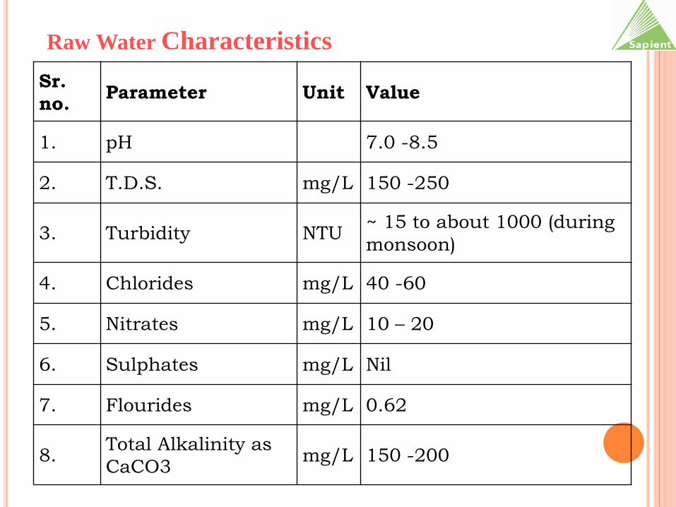
Raw Water Characteristics
Sr.
no. Parameter Unit Value
1. pH 7.0 -8.5
2. T.D.S. mg/L 150 -250
3. Turbidity NTU~ 15 to about 1000 (during
monsoon)
4. Chlorides mg/L 40 -60
5. Nitrates mg/L 10 – 20
6. Sulphates mg/L Nil
7. Flourides mg/L 0.62
8. Total Alkalinity as
CaCO3 mg/L 150 -200
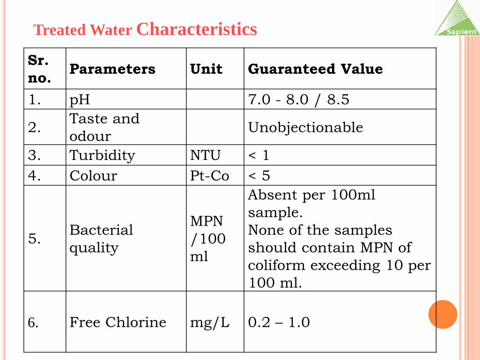
Treated Water Characteristics
Sr.
no. Parameters Unit Guaranteed Value
1. pH 7.0 - 8.0 / 8.5
2. Taste and
odourUnobjectionable
3. Turbidity NTU < 1
4. Colour Pt-Co < 5
5. Bacterial
quality
MPN
/100
ml
Absent per 100ml
sample.
None of the samples
should contain MPN of
coliform exceeding 10 per
100 ml.
6. Free Chlorine mg/L 0.2 – 1.0
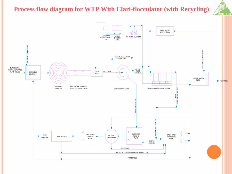
Process flow diagram for WTP With Clari-flocculator (with Recycling)
RAW WATERFROM RAW WATER
WITH PARSHALL FLUME
RAW WATER CHANNEL
FLASH
MIXER
CLARIFLOCCULATOR
BACK WASHWATER TANK
CLEAR WATERSUMP
CLARIFIER
CENTRIFUGE SUMP &CAKE
DISPOSAL
RAPID GRAVITY SAND FILTER
PUMP
INLET PIPE
BACKW
ASH
WATER
BACKW
ASH
WATER
PRE C
HLO
RIN
ATIO
N
BACK WASHRECYCLING
TANK
FILTER INLET
CHANNEL
AIR WASH BLOWERS
FILTRATE TO BACKWASH RECYCLING TANK
CLARIFIER S
LU
DG
E
CASCADEAERATOR
RECEIVINGCHAMBER
TO RECYCLE
SETTLESLUDGE
PUMP HOUSE
PO
ST C
HLO
RIN
ATIO
N
CLARIFLOCCULATORBYPASS LINE
ALUMDOSING
TANK
CONSTANTHEAD DOSING
TANK
DIRTY
SLUDGE THCIKENER
THICKENEDSUMP &PUMP
SUPERNANT
TO SUPPLY
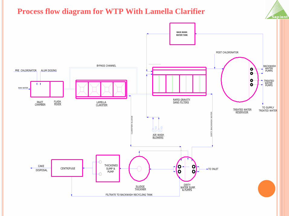
Process flow diagram for WTP With Lamella Clarifier
RAW WATER
INLET FLASH MIXER
BYPASS CHANNEL
CLARIFIER S
LU
DG
E
BACK WASH
WATER TANK
AIR WASH BLOWERS
SAND FILTERS
TREATED WATERRESERVOIR
DIRTY
THICKNER
LAMELLACLARIFIER
WATER SUMP & PUMPS
RAPID GRAVITY
SLUDGE
CHAMBER
POST CHLORINATOR
TO INLET
DIRTY B
ACKW
ASH
WATER
TO SUPPLYTREATED WATER
BACKWASHWATER PUMPS
TREATEDWATER PUMPS
CENTRIFUGETHICKENED
SUMP &PUMP
CAKE
DISPOSAL
FILTRATE TO BACKWASH RECYCLING TANK
PRE CHLORINATOR ALUM DOSING
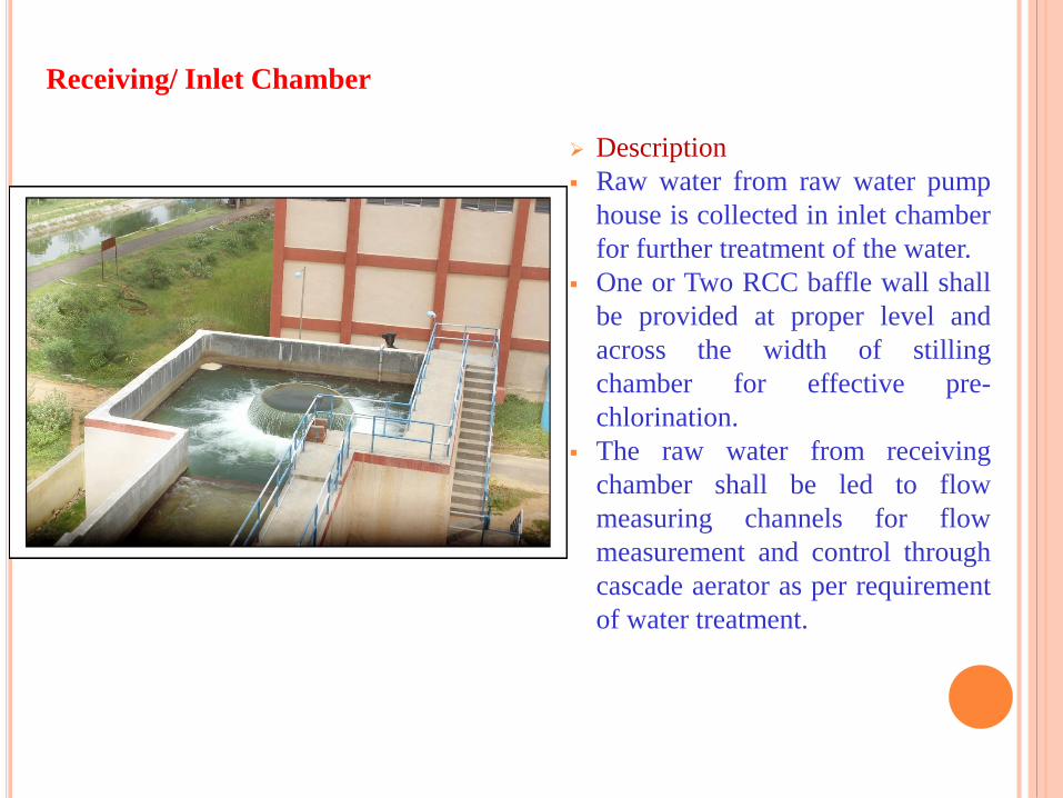
Receiving/ Inlet Chamber
Description
Raw water from raw water pump
house is collected in inlet chamber
for further treatment of the water.
One or Two RCC baffle wall shall
be provided at proper level and
across the width of stilling
chamber for effective pre-
chlorination.
The raw water from receiving
chamber shall be led to flow
measuring channels for flow
measurement and control through
cascade aerator as per requirement
of water treatment.
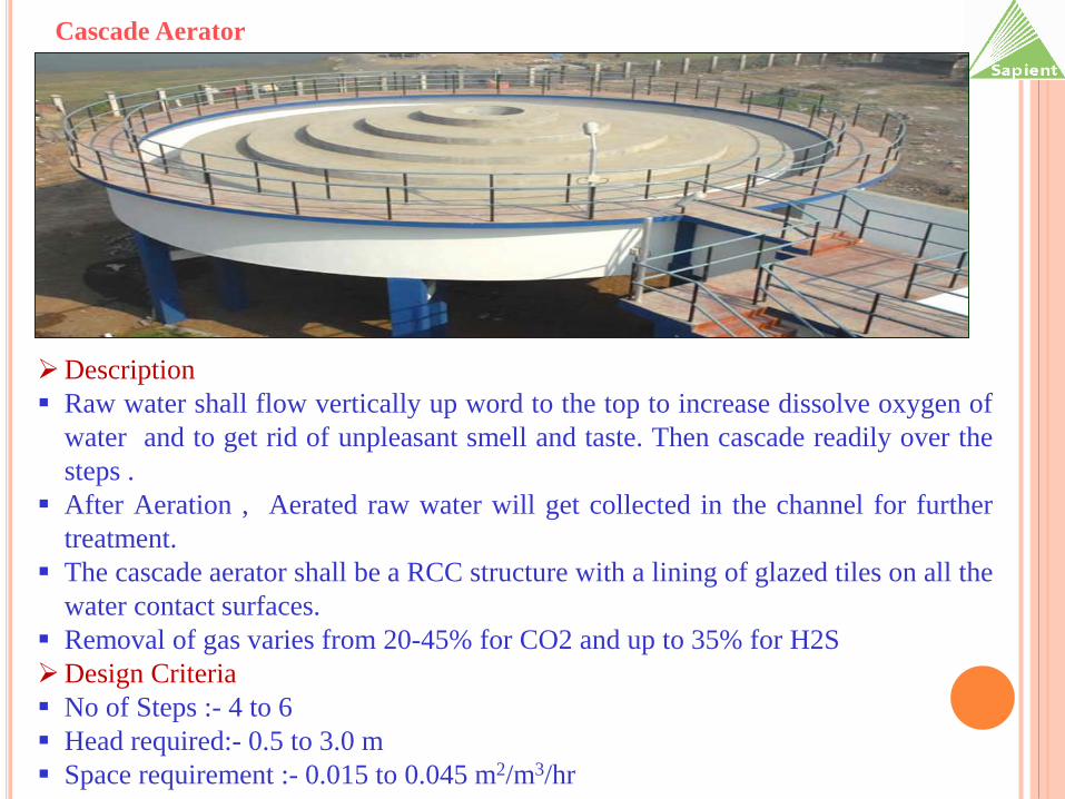
Cascade Aerator
Description
Raw water shall flow vertically up word to the top to increase dissolve oxygen of
water and to get rid of unpleasant smell and taste. Then cascade readily over the
steps .
After Aeration , Aerated raw water will get collected in the channel for further
treatment.
The cascade aerator shall be a RCC structure with a lining of glazed tiles on all the
water contact surfaces.
Removal of gas varies from 20-45% for CO2 and up to 35% for H2S
Design Criteria
No of Steps :- 4 to 6
Head required:- 0.5 to 3.0 m
Space requirement :- 0.015 to 0.045 m2/m3/hr
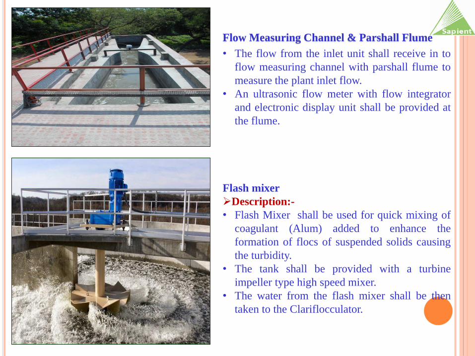
Flow Measuring Channel & Parshall Flume
• The flow from the inlet unit shall receive in to
flow measuring channel with parshall flume to
measure the plant inlet flow.
• An ultrasonic flow meter with flow integrator
and electronic display unit shall be provided at
the flume.
Flash mixer
Description:-
• Flash Mixer shall be used for quick mixing of
coagulant (Alum) added to enhance the
formation of flocs of suspended solids causing
the turbidity.
• The tank shall be provided with a turbine
impeller type high speed mixer.
• The water from the flash mixer shall be then
taken to the Clariflocculator.
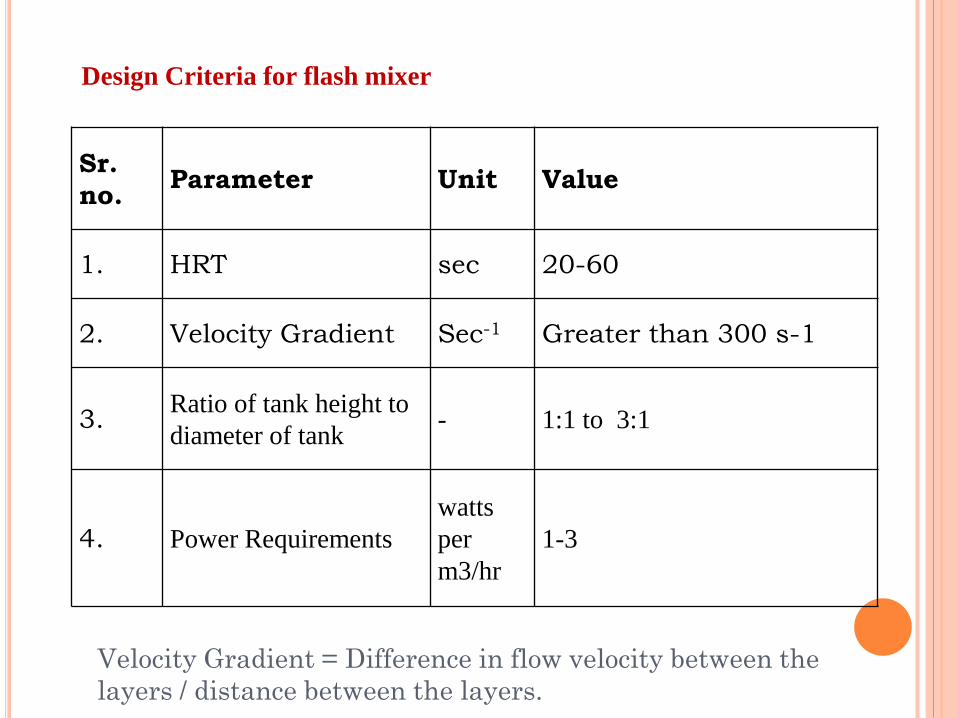
Design Criteria for flash mixer
Sr.
no. Parameter Unit Value
1. HRT sec 20-60
2. Velocity Gradient Sec-1 Greater than 300 s-1
3. Ratio of tank height to
diameter of tank - 1:1 to 3:1
4. Power Requirements
watts
per
m3/hr
1-3
Velocity Gradient = Difference in flow velocity between the
layers / distance between the layers.

Description
Clarification process is the removal of suspended solids from the raw water.
The water from Flash mixer shall flow to the flocculation zone of Clariflocculator. The
flocculation compartment shall be provided. The gentle mixing of the content (with help
of slow moving flocculation paddles) shall form the flocs, which will be settled in the
Clarifier zone by gravity. It shall remove the turbidity and precipitates of hard water
formed in the flash mixer.
The settled sludge shall be collected into the sludge pocket and then it shall be
discharged off to the Clarifier Sludge Sump. The operation of sludge withdrawal will
depend on the concentration of inlet turbidity of water.
The over flows from the clarifier units shall be taken to the rapid sand filters through the
filter inlet channel.
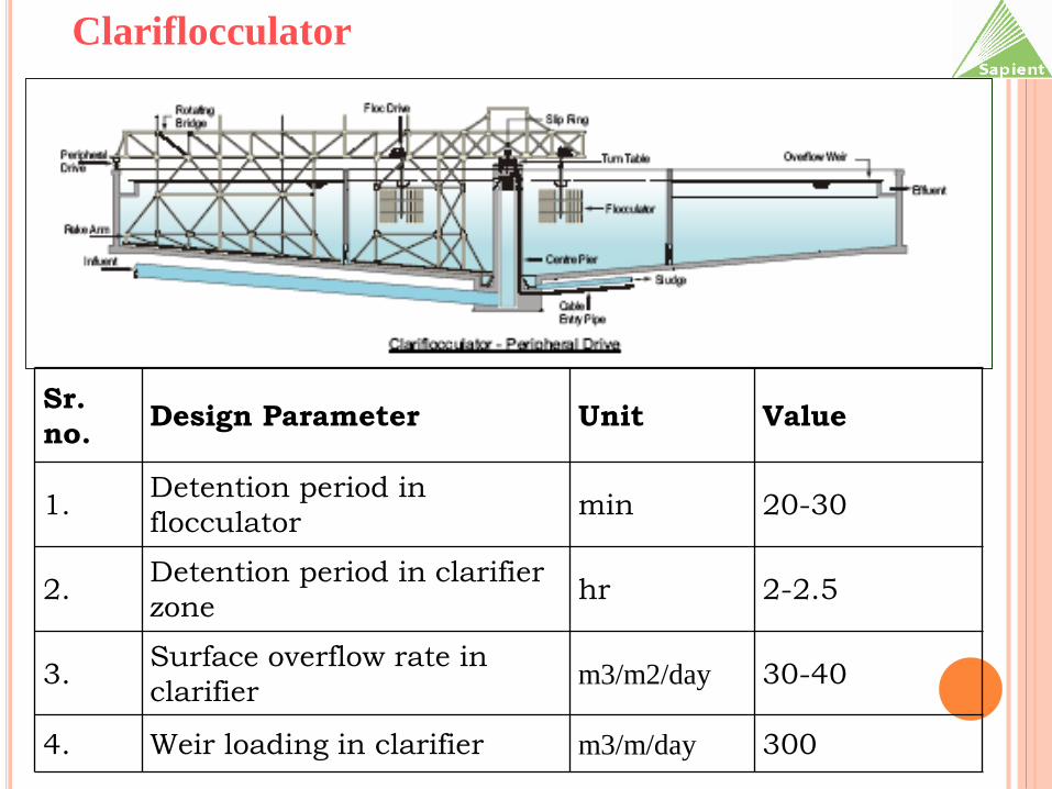
Clariflocculator
Clariflocculator
Sr.
no. Design Parameter Unit Value
1. Detention period in
flocculatormin 20-30
2. Detention period in clarifier
zonehr 2-2.5
3. Surface overflow rate in
clarifierm3/m2/day 30-40
4. Weir loading in clarifier m3/m/day 300
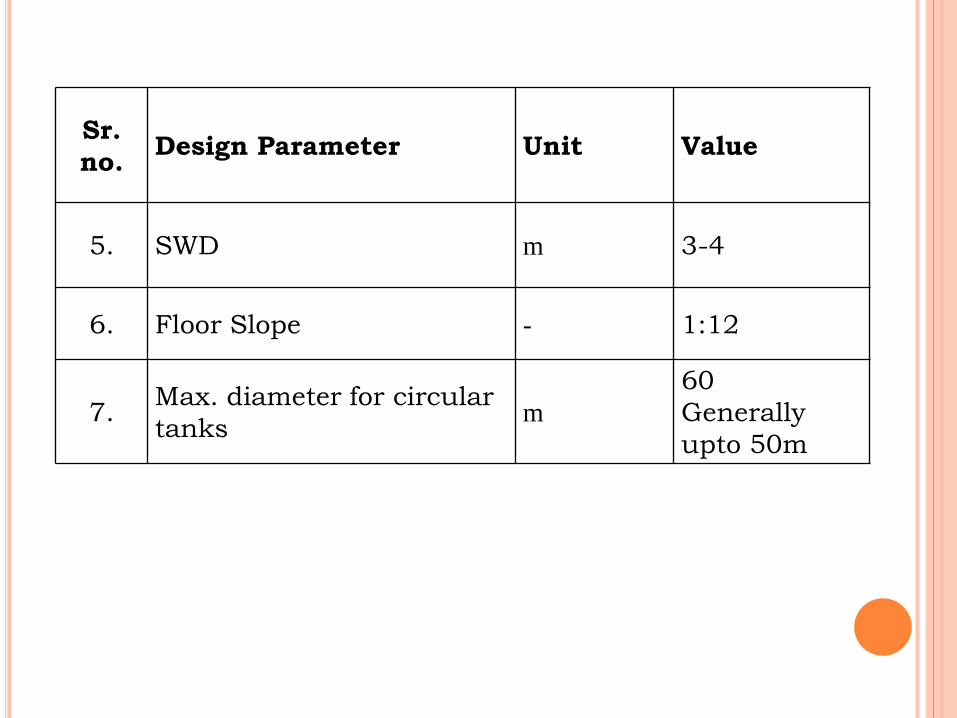
Sr.
no. Design Parameter Unit Value
5. SWD m 3-4
6. Floor Slope - 1:12
7. Max. diameter for circular
tanks m
60
Generally
upto 50m
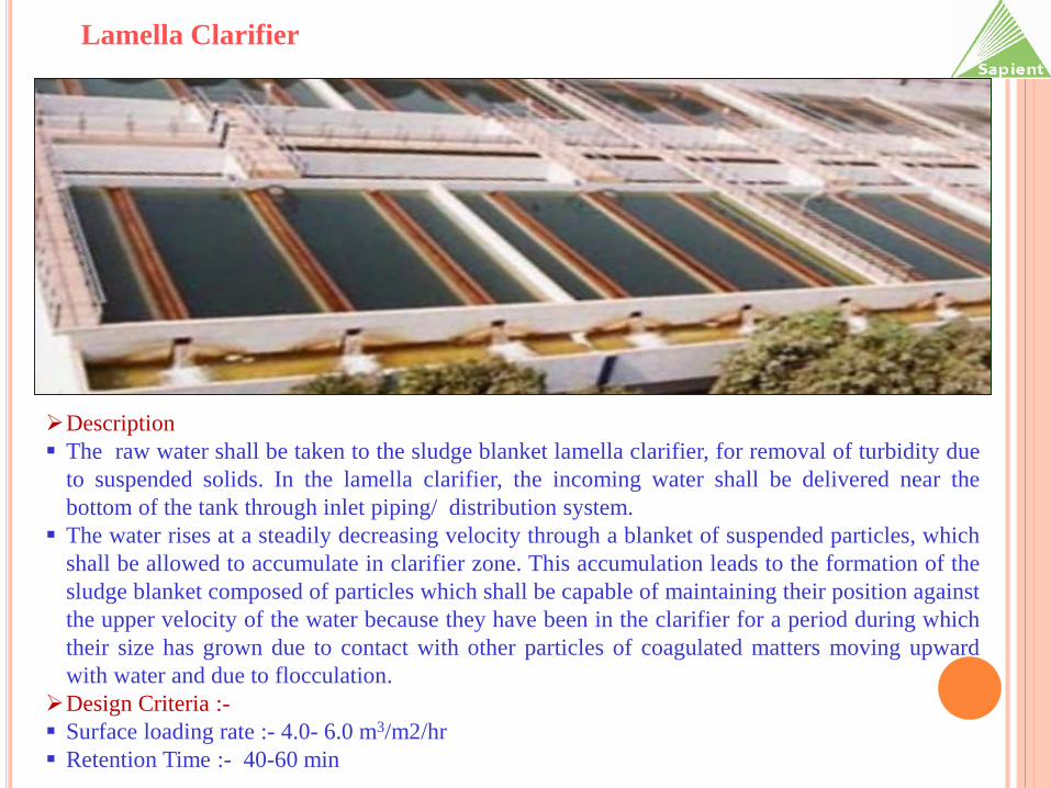
Description
The raw water shall be taken to the sludge blanket lamella clarifier, for removal of turbidity due
to suspended solids. In the lamella clarifier, the incoming water shall be delivered near the
bottom of the tank through inlet piping/ distribution system.
The water rises at a steadily decreasing velocity through a blanket of suspended particles, which
shall be allowed to accumulate in clarifier zone. This accumulation leads to the formation of the
sludge blanket composed of particles which shall be capable of maintaining their position against
the upper velocity of the water because they have been in the clarifier for a period during which
their size has grown due to contact with other particles of coagulated matters moving upward
with water and due to flocculation.
Design Criteria :-
Surface loading rate :- 4.0- 6.0 m3/m2/hr
Retention Time :- 40-60 min
Lamella Clarifier
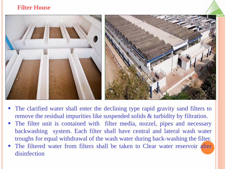
The clarified water shall enter the declining type rapid gravity sand filters to
remove the residual impurities like suspended solids & turbidity by filtration.
The filter unit is contained with filter media, nozzel, pipes and necessary
backwashing system. Each filter shall have central and lateral wash water
troughs for equal withdrawal of the wash water during back-washing the filter.
The filtered water from filters shall be taken to Clear water reservoir after
disinfection
Filter House
Filter House
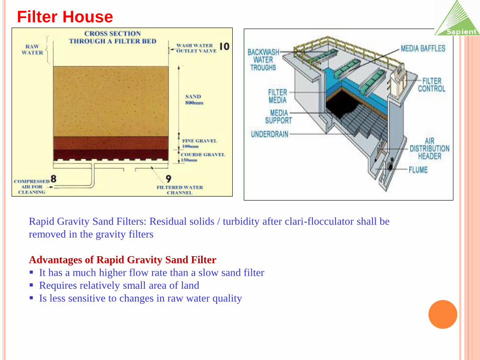
Rapid Gravity Sand Filters: Residual solids / turbidity after clari-flocculator shall be
removed in the gravity filters
Advantages of Rapid Gravity Sand Filter
It has a much higher flow rate than a slow sand filter
Requires relatively small area of land
Is less sensitive to changes in raw water quality
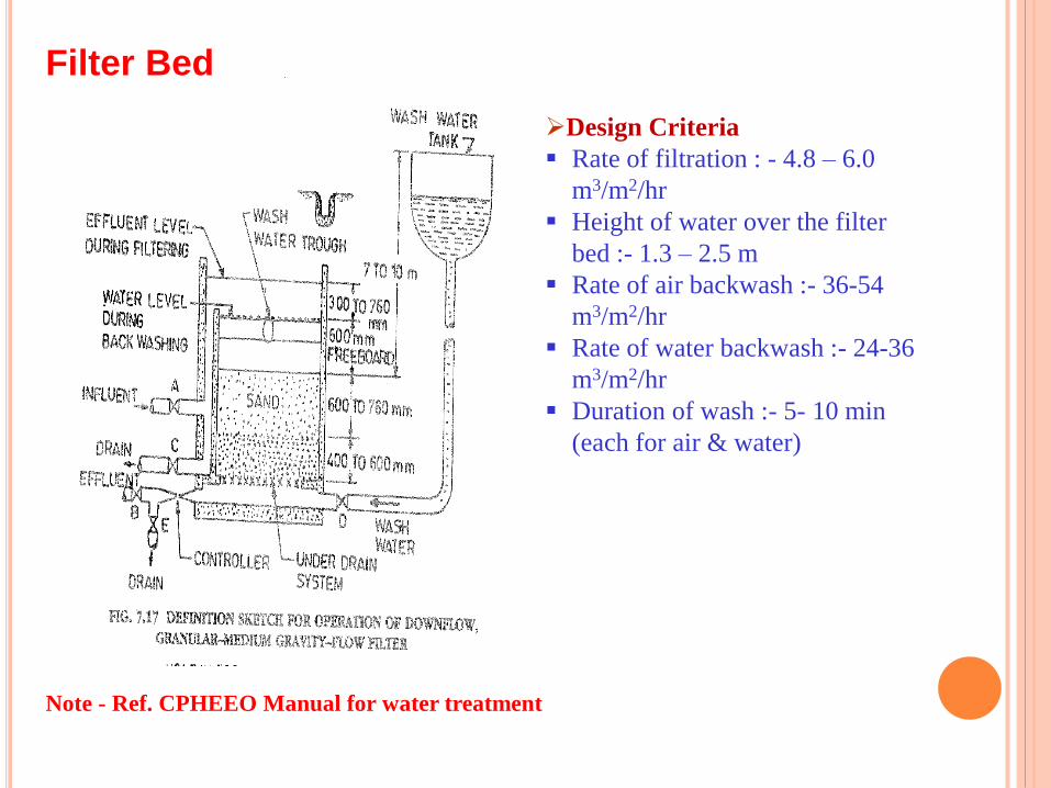
Design Criteria
Rate of filtration : - 4.8 – 6.0
m3/m2/hr
Height of water over the filter
bed :- 1.3 – 2.5 m
Rate of air backwash :- 36-54
m3/m2/hr
Rate of water backwash :- 24-36
m3/m2/hr
Duration of wash :- 5- 10 min
(each for air & water)
Note - Ref. CPHEEO Manual for water treatment
Filter Bed
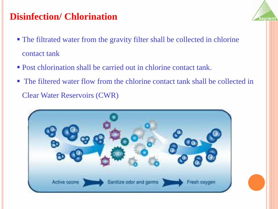
Disinfection/ Chlorination
The filtrated water from the gravity filter shall be collected in chlorine
contact tank
Post chlorination shall be carried out in chlorine contact tank.
The filtered water flow from the chlorine contact tank shall be collected in
Clear Water Reservoirs (CWR)

Description
• The main function of sludge thickener is to increase the concentration of solids by removing
a portion of the liquid fraction from sludge; which is generated from clarification treatment.
• The concentration of sludge shall be increased from 1- 1.5 % up to 4 – 5 % by gravity
settlement of the inlet solids.
• The conditioning polyelectrolyte shall be added to thickener for enhancing gravity
separation with the help of polyelectrolyte dosing tank.
• The underflow of thickened sludge from thickener shall be fed to the Thickened sludge sump
and the supernatant shall be taken to the backwash recycling tank.
Design Criteria:
• Solid Loading rate :- 50-75 kg/m2/day (Normally 60 kg/m2/day)
• Inlet concentration :- 1 – 1.1 %
• Outlet concentration :- 4 -5 %
• Bottom Slope:- 1:8
Sludge Thickener
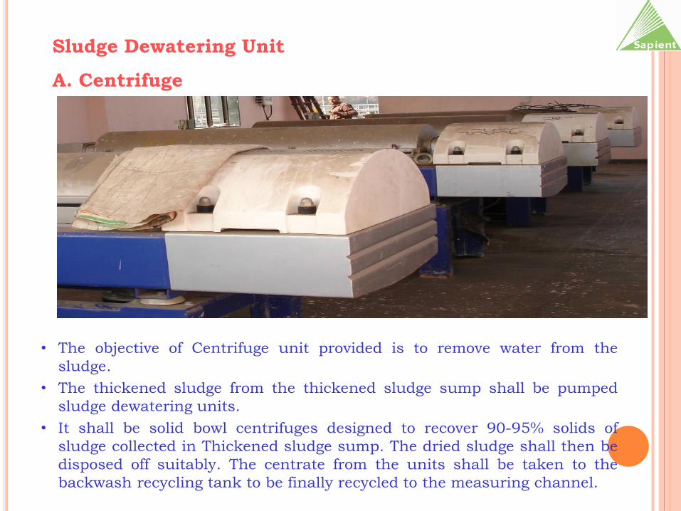
Sludge Dewatering Unit
A. Centrifuge
• The objective of Centrifuge unit provided is to remove water from the
sludge.
• The thickened sludge from the thickened sludge sump shall be pumped
sludge dewatering units.
• It shall be solid bowl centrifuges designed to recover 90-95% solids of
sludge collected in Thickened sludge sump. The dried sludge shall then be
disposed off suitably. The centrate from the units shall be taken to the
backwash recycling tank to be finally recycled to the measuring channel.
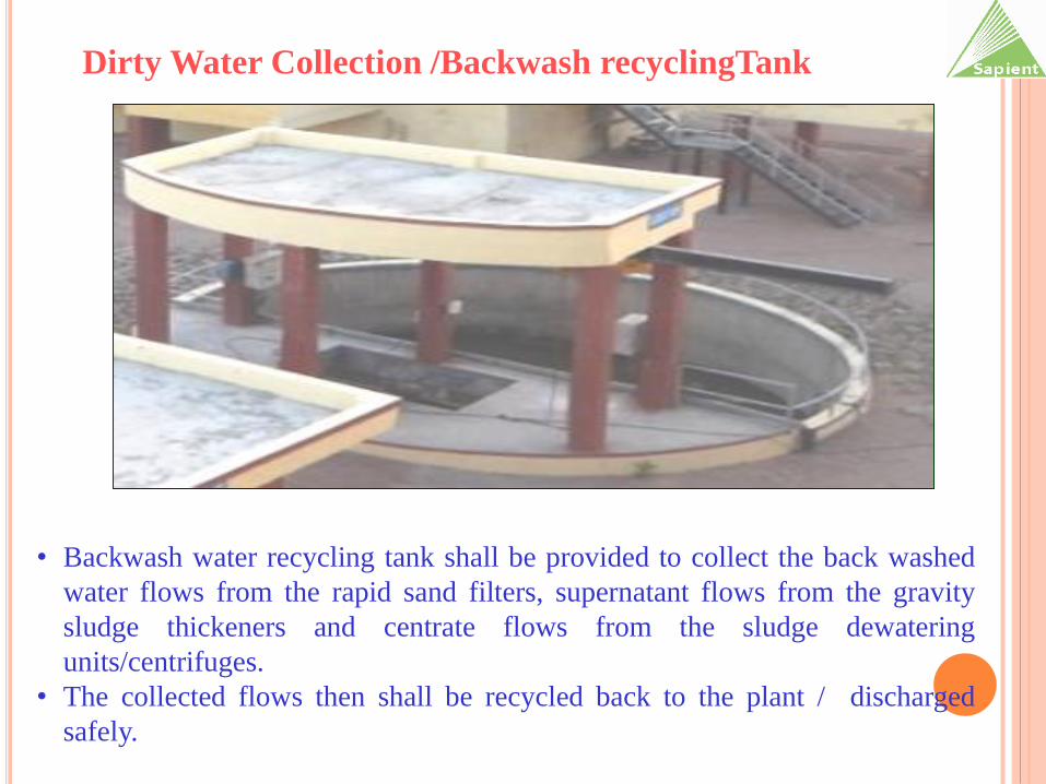
• Backwash water recycling tank shall be provided to collect the back washed
water flows from the rapid sand filters, supernatant flows from the gravity
sludge thickeners and centrate flows from the sludge dewatering
units/centrifuges.
• The collected flows then shall be recycled back to the plant / discharged
safely.
Dirty Water Collection /Backwash recyclingTank

THANKS

PRESENTATION ON PUMPS
FUNCTIONS,
PREVENTIVE MAINTENANCE & TROUBLESHOOTING
Surat Office:
413, Trinity Cyygnus
Nr. Someswar BRTS Junction, University Rd.
Surat – 395 007.
Tel.: 0261 – 2974111
E-mail: [email protected]
Ahmedabad Office:
701, Rembrandt,
Opp. Associated Petrol Pump,
C.G. Road, Ahmedabad - 380 006
Tel.: +91 - 79 – 26422105
E-mail : [email protected]

• Introduction
• Terminology
• Basic of Pump Engineering
• Classifications of Pumps
• Selection of Pumps & Prime Movers
• Piping & Plant Lay out
• Installation of Pumps
• Operation of Pumps
• Preventive Maintenance
• Trouble Shooting
Introduction
In Water Supply System:
• Lifting water from source to purification plant or to
service reservoir.
• Boosting water from source to low service areas and
to OHT of multistoried buildings
• Transporting water through treatment plant, draining of
settling tanks and other treatment units
• Withdrawing sludge
• Supplying water under pressure to operating
equipment
• Pumping chemicals solutions to treatment units.
IntroductionIn Sewage & Waste Water Handling System:
• Lifting sewage from collecting sump to distribution chamber of treatment plant
• Boosting sewage from intermediate pumping station to terminal pumping station or to discharge into another gravity sewer.
• Disposing leakages from dry well of pumping stations
• Transporting sewage through treatment plant, draining of settling tanks and other treatment units
• Transferring overflow or Excess sewage
TERMINOLOGY• Pump
• Performance curve
• Head
• Capacity / Discharge / Flow
• Speed (in RPM)
• Efficiency
• Shut off head
• Run out head
• NPSH(R) & NPSH(A)
• Pump Input or BKW/BHP
• System head
What is Pump ?
It is a mechanical equipment adding energy
to the fluid to move it from one point to
another or raising its pressure or to transfer
from a low pressure region to a high
pressure region.
Head & Capacity• What is Head ?
HEAD - A height of a liquid column.
Expressed in mt., kg / cm^2, psi, mlc
• Capacity / Discharge / Flow
Quantum of liquid delivered by pump in specific time.
Expressed in LPS, LPM, USGPM, IGPM, Cu.Mt / hr.,
Cusec
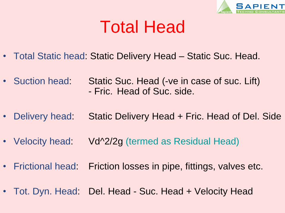
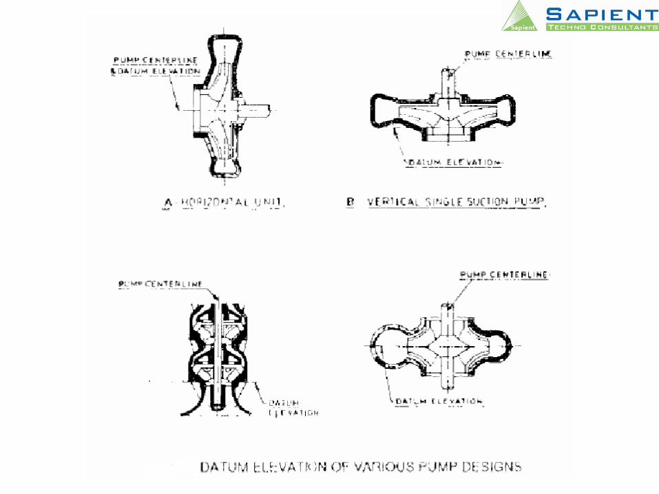
Total Head
• Total Static head: Static Delivery Head – Static Suc. Head.
• Suction head: Static Suc. Head (-ve in case of suc. Lift) - Fric. Head of Suc. side.
• Delivery head: Static Delivery Head + Fric. Head of Del. Side
• Velocity head: Vd^2/2g (termed as Residual Head)
• Frictional head: Friction losses in pipe, fittings, valves etc.
• Tot. Dyn. Head: Del. Head - Suc. Head + Velocity Head
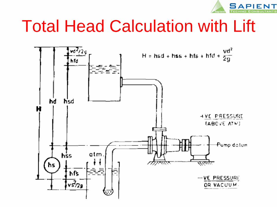
Total Head Calculation with Lift
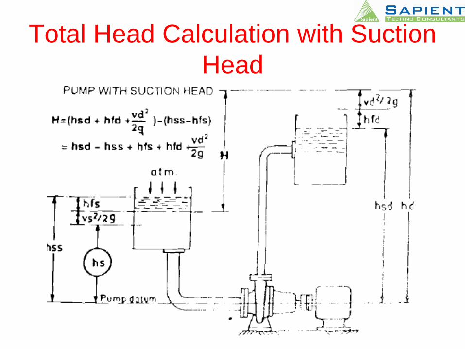
Total Head Calculation with Suction
Head
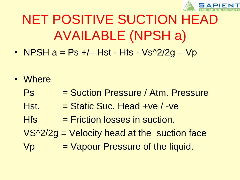
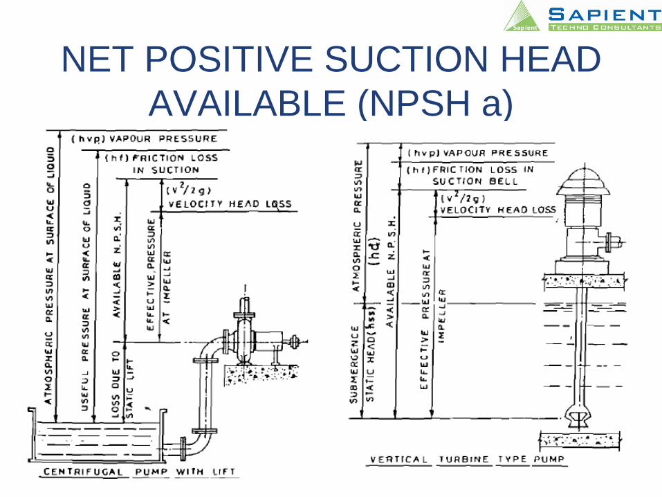
NET POSITIVE SUCTION HEAD
AVAILABLE (NPSH a)• NPSH a = Ps +/– Hst - Hfs - Vs^2/2g – Vp
• Where
Ps = Suction Pressure / Atm. Pressure
Hst. = Static Suc. Head +ve / -ve
Hfs = Friction losses in suction.
VS^2/2g = Velocity head at the suction face
Vp = Vapour Pressure of the liquid.
NET POSITIVE SUCTION HEAD
AVAILABLE (NPSH a)
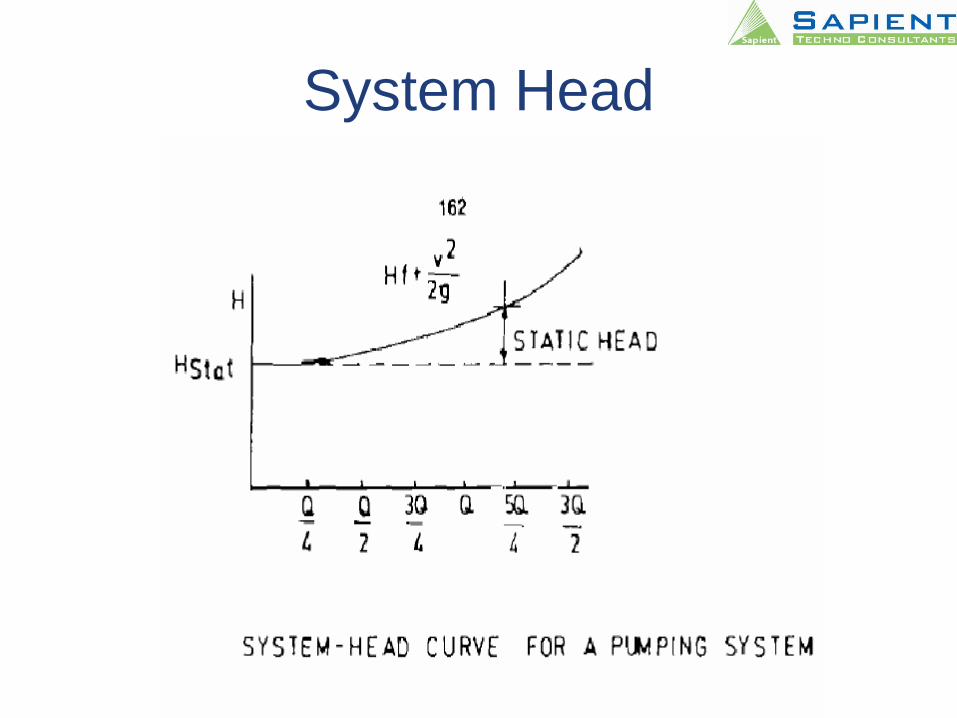
System Head
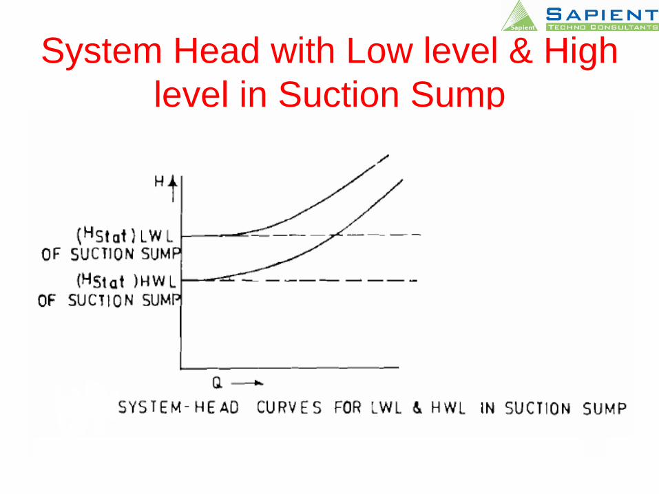
System Head with Low level & High
level in Suction Sump
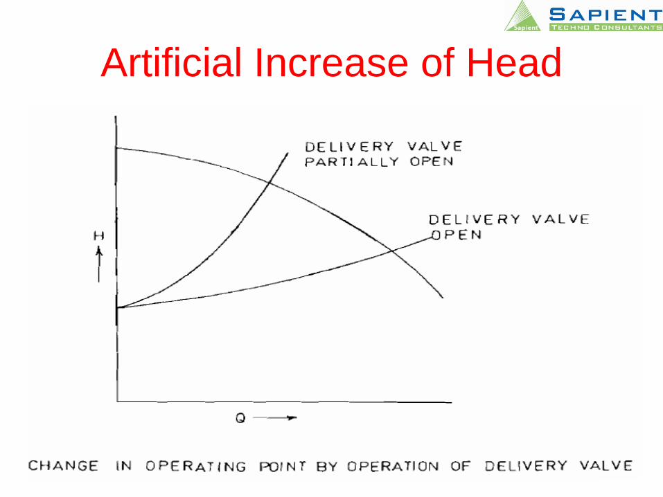
Artificial Increase of Head
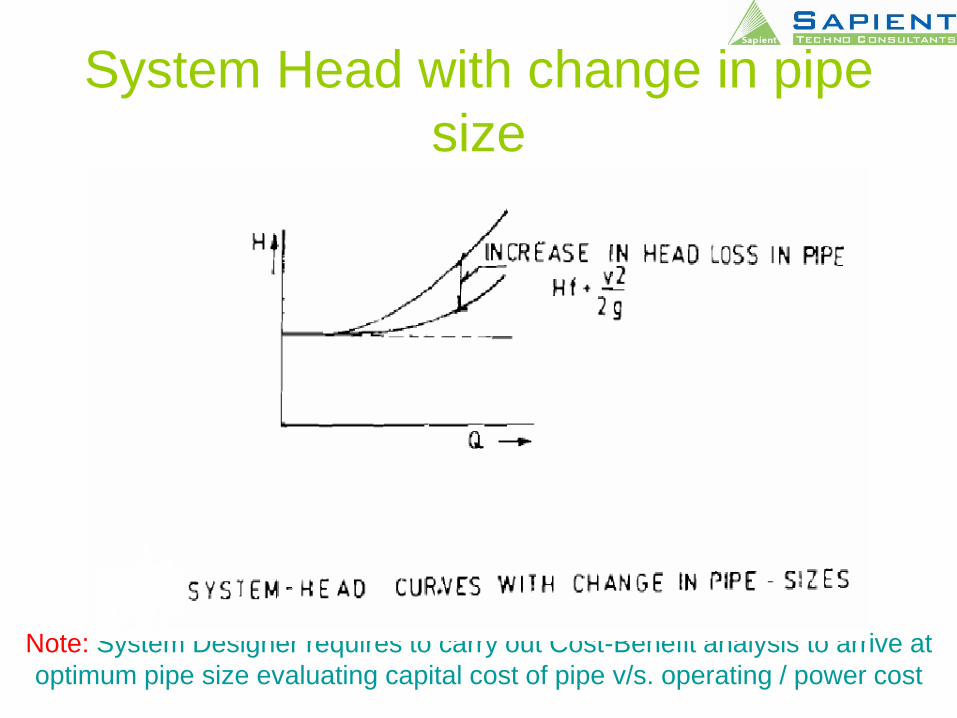
System Head with change in pipe
size
Note: System Designer requires to carry out Cost-Benefit analysis to arrive at
optimum pipe size evaluating capital cost of pipe v/s. operating / power cost
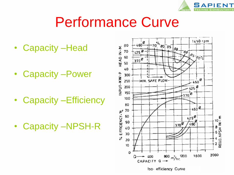
Performance Curve
• Capacity –Head
• Capacity –Power
• Capacity –Efficiency
• Capacity –NPSH-R
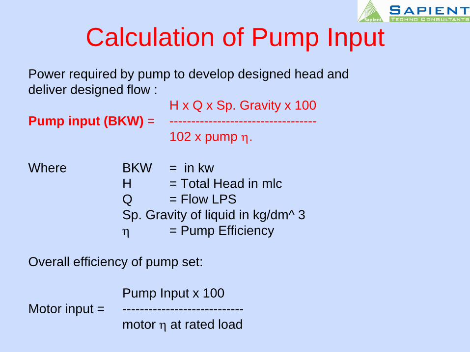
Calculation of Pump Input
Power required by pump to develop designed head and
deliver designed flow :
H x Q x Sp. Gravity x 100
Pump input (BKW) = ----------------------------------
102 x pump h.
Where BKW = in kw
H = Total Head in mlc
Q = Flow LPS
Sp. Gravity of liquid in kg/dm^ 3
h = Pump Efficiency
Overall efficiency of pump set:
Pump Input x 100
Motor input = ----------------------------
motor h at rated load
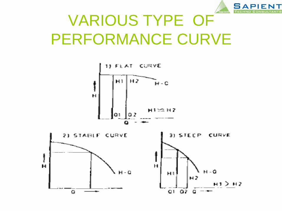
VARIOUS TYPE OF
PERFORMANCE CURVE
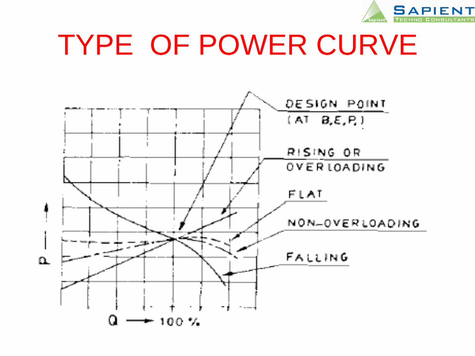
TYPE OF POWER CURVE
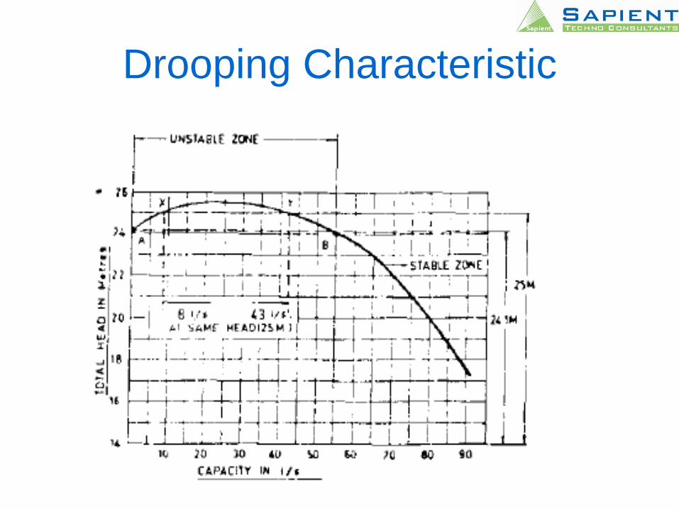
Drooping Characteristic
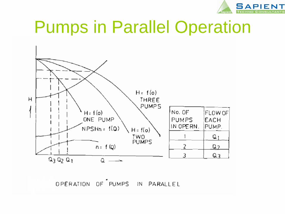
Pumps in Parallel Operation

Closed & Semi Open Single Vane
Impeller
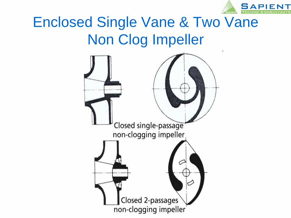
Enclosed Single Vane & Two Vane
Non Clog Impeller

‘S’ Type and Three Vanes Non Clog
Impeller
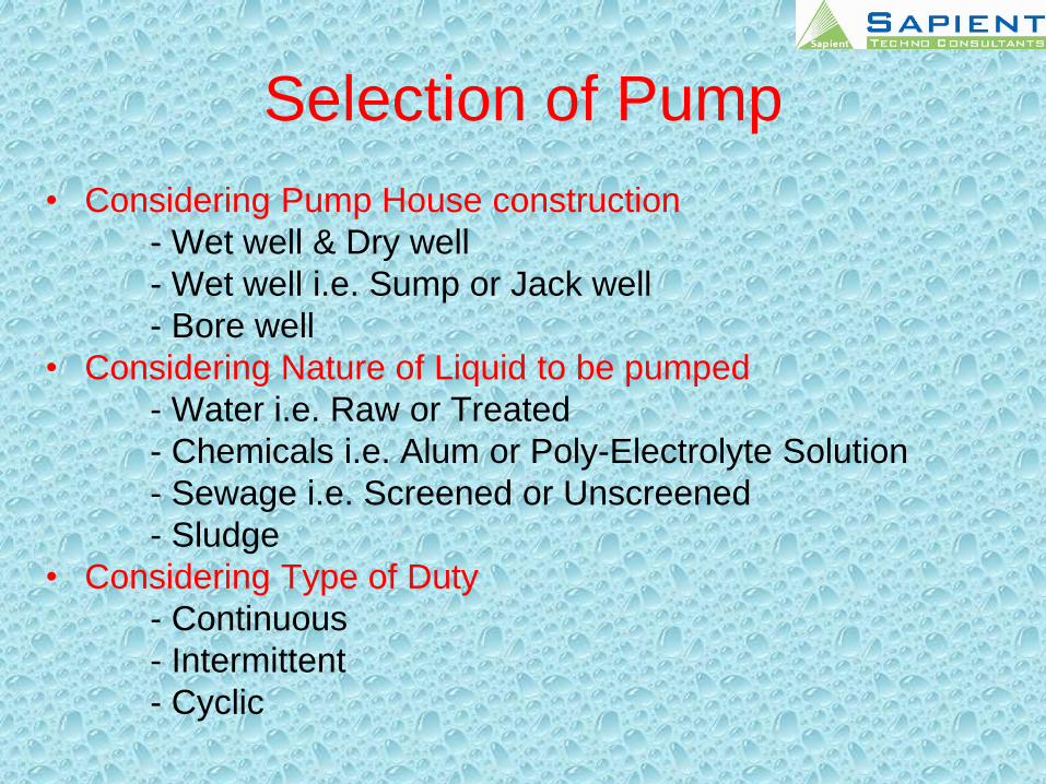
Selection of Pump
• Considering Pump House construction
- Wet well & Dry well
- Wet well i.e. Sump or Jack well
- Bore well
• Considering Nature of Liquid to be pumped
- Water i.e. Raw or Treated
- Chemicals i.e. Alum or Poly-Electrolyte Solution
- Sewage i.e. Screened or Unscreened
- Sludge
• Considering Type of Duty
- Continuous
- Intermittent
- Cyclic

Selection of Pump
• Considering Present and Projected demand and pattern of change in demand
• Considering Head and Total Flow rate requirement
• Considering the efficiency of pump /s and consequent influence on power consumption and power cost
• Considering various options possible by permuting the parameters of the pumping system, including
-Capacity
-Number of pumps ( working & Standbys)
-combining them in parallel or series
• Considering different modes of Installation in respect to
-cost of civil structure
-ease of operation and maintenance
-overall economics
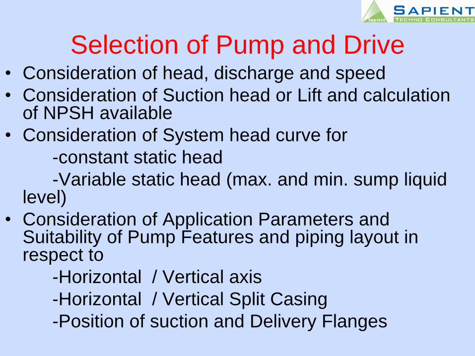
Selection of Pump and Drive• Consideration of head, discharge and speed
• Consideration of Suction head or Lift and calculation of NPSH available
• Consideration of System head curve for
-constant static head
-Variable static head (max. and min. sump liquid level)
• Consideration of Application Parameters and Suitability of Pump Features and piping layout in respect to
-Horizontal / Vertical axis
-Horizontal / Vertical Split Casing
-Position of suction and Delivery Flanges
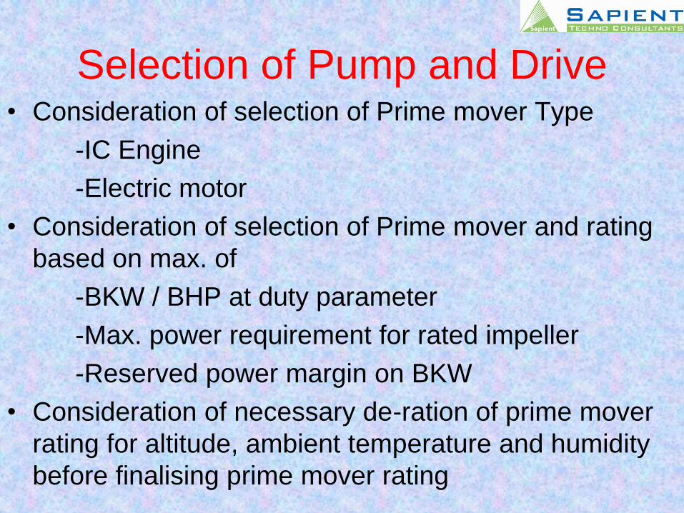
Selection of Pump and Drive• Consideration of selection of Prime mover Type
-IC Engine
-Electric motor
• Consideration of selection of Prime mover and rating
based on max. of
-BKW / BHP at duty parameter
-Max. power requirement for rated impeller
-Reserved power margin on BKW
• Consideration of necessary de-ration of prime mover
rating for altitude, ambient temperature and humidity
before finalising prime mover rating
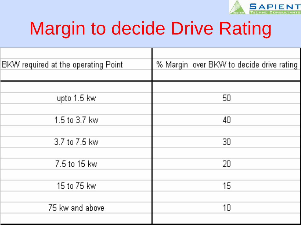
Margin to decide Drive Rating
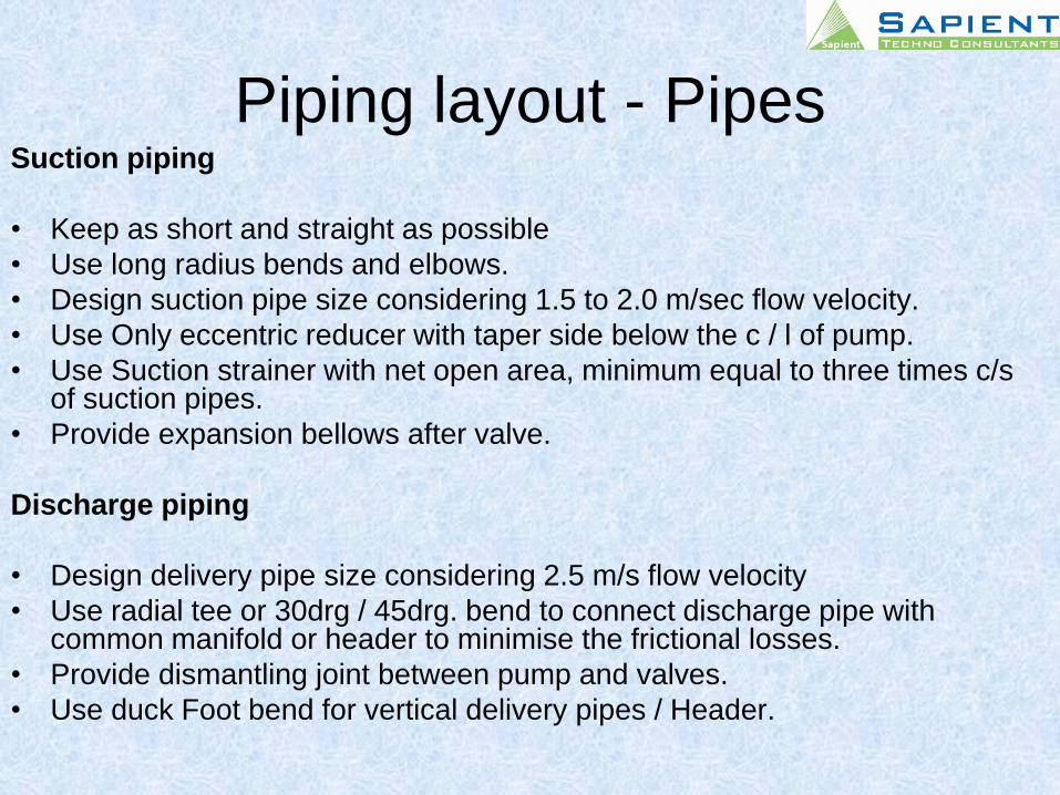
Piping layout - PipesSuction piping
• Keep as short and straight as possible
• Use long radius bends and elbows.
• Design suction pipe size considering 1.5 to 2.0 m/sec flow velocity.
• Use Only eccentric reducer with taper side below the c / l of pump.
• Use Suction strainer with net open area, minimum equal to three times c/s of suction pipes.
• Provide expansion bellows after valve.
Discharge piping
• Design delivery pipe size considering 2.5 m/s flow velocity
• Use radial tee or 30drg / 45drg. bend to connect discharge pipe with common manifold or header to minimise the frictional losses.
• Provide dismantling joint between pump and valves.
• Use duck Foot bend for vertical delivery pipes / Header.
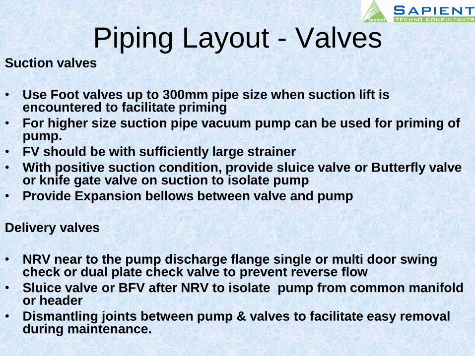
Piping Layout - ValvesSuction valves
• Use Foot valves up to 300mm pipe size when suction lift is encountered to facilitate priming
• For higher size suction pipe vacuum pump can be used for priming of pump.
• FV should be with sufficiently large strainer
• With positive suction condition, provide sluice valve or Butterfly valve or knife gate valve on suction to isolate pump
• Provide Expansion bellows between valve and pump
Delivery valves
• NRV near to the pump discharge flange single or multi door swing check or dual plate check valve to prevent reverse flow
• Sluice valve or BFV after NRV to isolate pump from common manifold or header
• Dismantling joints between pump & valves to facilitate easy removal during maintenance.
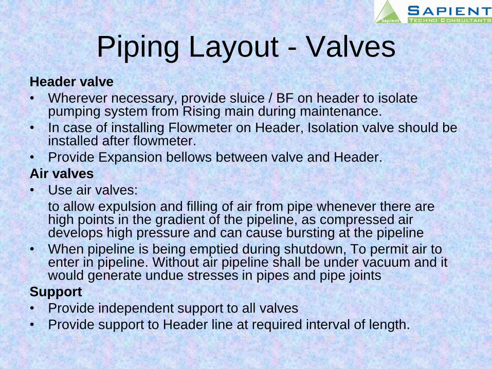
Piping Layout - ValvesHeader valve
• Wherever necessary, provide sluice / BF on header to isolate pumping system from Rising main during maintenance.
• In case of installing Flowmeter on Header, Isolation valve should be installed after flowmeter.
• Provide Expansion bellows between valve and Header.
Air valves
• Use air valves:
to allow expulsion and filling of air from pipe whenever there are high points in the gradient of the pipeline, as compressed air develops high pressure and can cause bursting at the pipeline
• When pipeline is being emptied during shutdown, To permit air to enter in pipeline. Without air pipeline shall be under vacuum and it would generate undue stresses in pipes and pipe joints
Support
• Provide independent support to all valves
• Provide support to Header line at required interval of length.
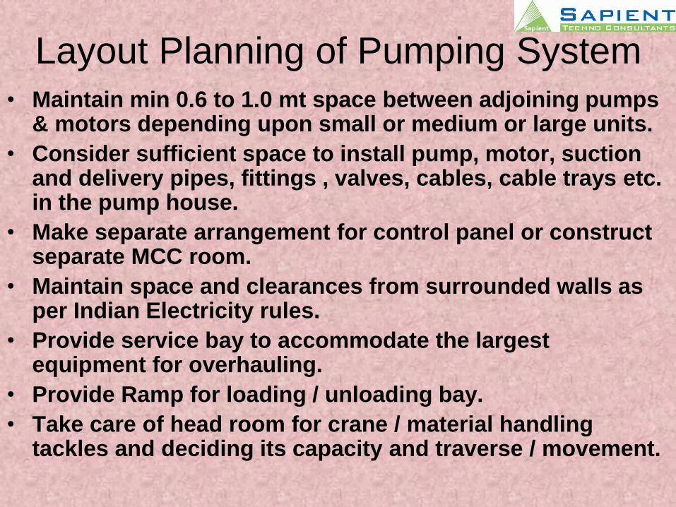
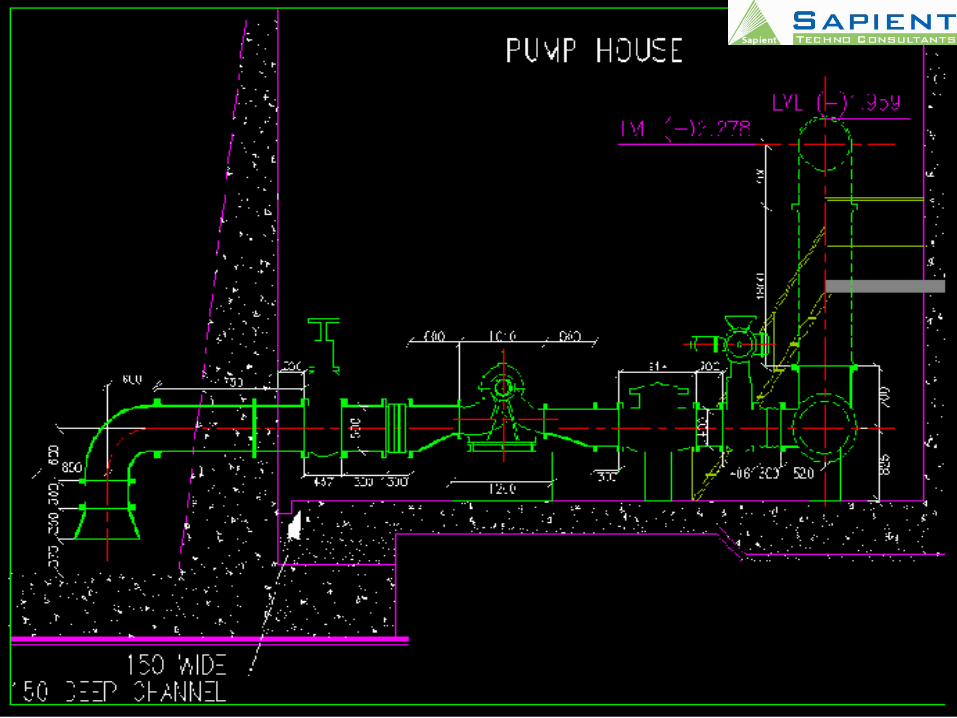
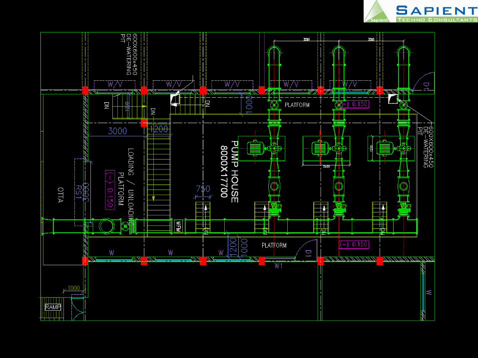
Layout Planning of Pumping System• Maintain min 0.6 to 1.0 mt space between adjoining pumps
& motors depending upon small or medium or large units.
• Consider sufficient space to install pump, motor, suction and delivery pipes, fittings , valves, cables, cable trays etc. in the pump house.
• Make separate arrangement for control panel or construct separate MCC room.
• Maintain space and clearances from surrounded walls as per Indian Electricity rules.
• Provide service bay to accommodate the largest equipment for overhauling.
• Provide Ramp for loading / unloading bay.
• Take care of head room for crane / material handling tackles and deciding its capacity and traverse / movement.

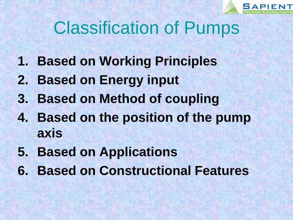
Classification of Pumps
1. Based on Working Principles
2. Based on Energy input
3. Based on Method of coupling
4. Based on the position of the pump
axis
5. Based on Applications
6. Based on Constructional Features
Based on Working Principles
-Centrifugal
-Positive Displacement
(Reciprocating-screw-gear, etc-lobe pump, vane
pump)
•Based on Energy input
-Hand pump
-Engine pumpset
-Electric pumpset
-Steam Turbine driven
•Based on Method of coupling
-Direct through Flex Couplings
-Unibuilt
-Belt driven
-Variable speed arrangement
-Right Angle Gear box driven
•Based on the position of the pump axis
-Horizontal
-Vertical Vertical Turbine Pump
Bore well submersible
Volute type sump pump
Submersible Non clog.
•Based on Application
-Water pump
-Dewatering pump
-Slurry pump
-Sewage pump
-Oil pump
-Effluent pump
•Based on Constructional Features
-Type of casing
Volute type
Diffuser / Turbine type
-Splitting of Casing
Horizontal Split case
Vertical Split Case
Inclined split case
-Type of Impeller
Single suction or Double Suction
Open, Semi - open or Enclosed
Single vane or two vane or multi vane
Radial or Mixed flow
Non log
Free Flow
-Number of stages
Single stage
Double stage
Multi stage
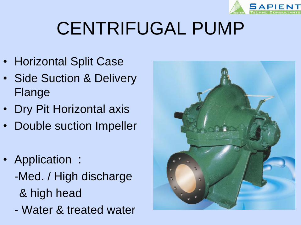
CENTRIFUGAL PUMP
• Horizontal Split Case
• Side Suction & Delivery
Flange
• Dry Pit Horizontal axis
• Double suction Impeller
• Application :
-Med. / High discharge
& high head
- Water & treated water
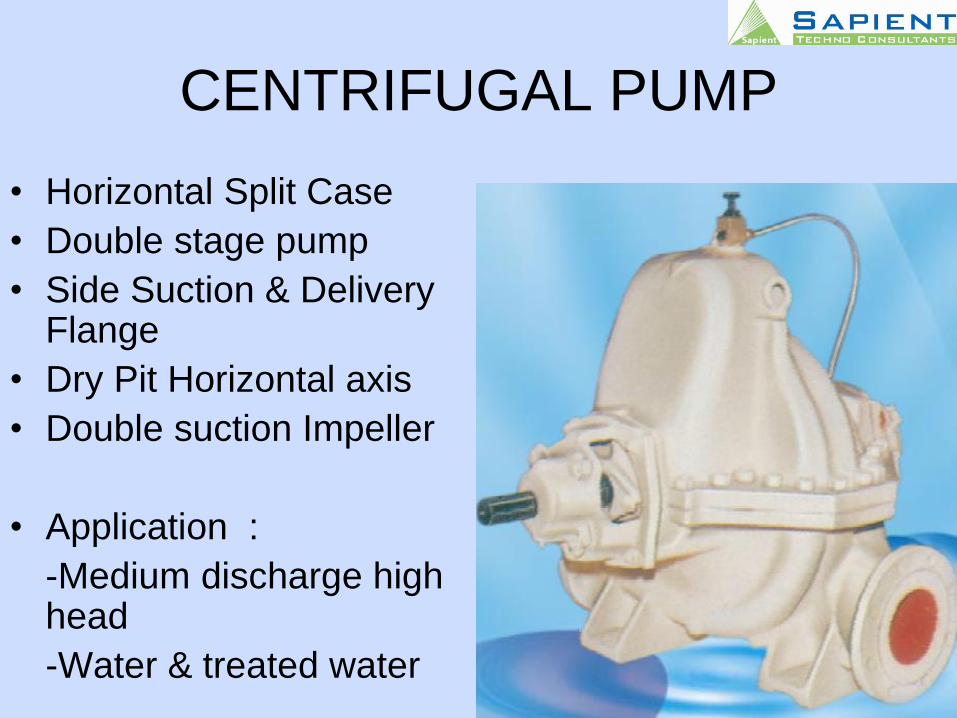
CENTRIFUGAL PUMP
• Horizontal Split Case
• Double stage pump
• Side Suction & Delivery Flange
• Dry Pit Horizontal axis
• Double suction Impeller
• Application :
-Medium discharge high head
-Water & treated water
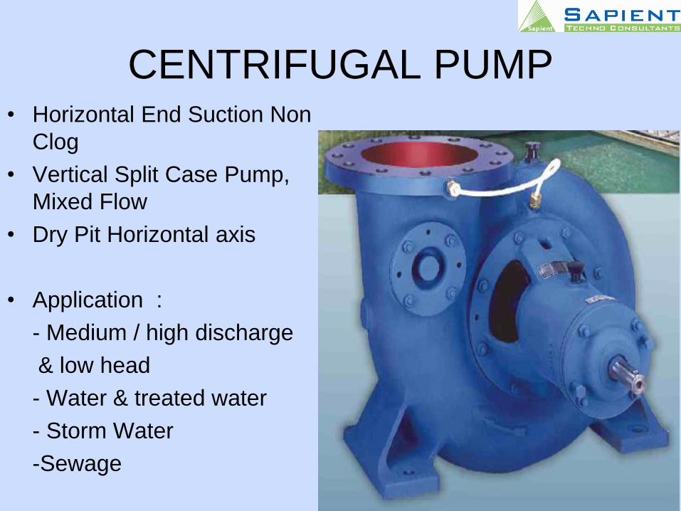
CENTRIFUGAL PUMP• Horizontal End Suction Non
Clog
• Vertical Split Case Pump,
Mixed Flow
• Dry Pit Horizontal axis
• Application :
- Medium / high discharge
& low head
- Water & treated water
- Storm Water
-Sewage
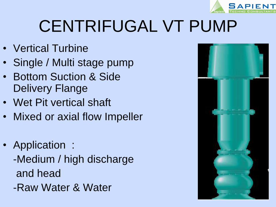
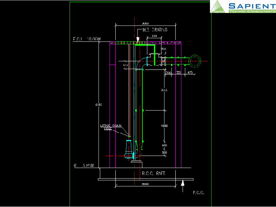
CENTRIFUGAL VT PUMP
• Vertical Turbine
• Single / Multi stage pump
• Bottom Suction & Side Delivery Flange
• Wet Pit vertical shaft
• Mixed or axial flow Impeller
• Application :
-Medium / high discharge
and head
-Raw Water & Water
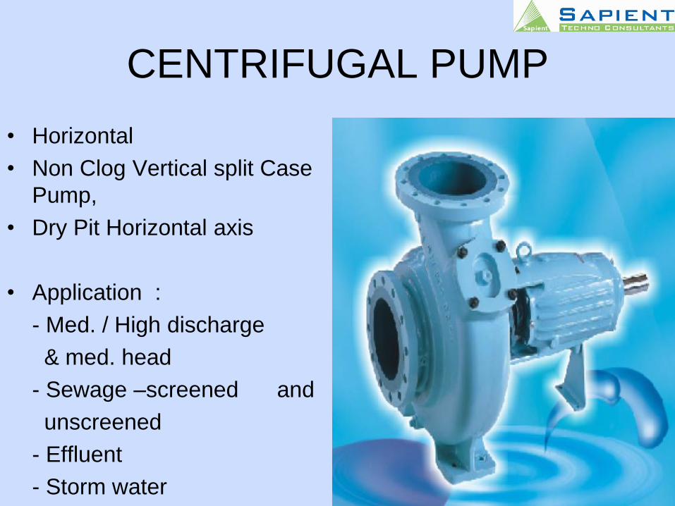
CENTRIFUGAL PUMP
• Horizontal
• Non Clog Vertical split Case
Pump,
• Dry Pit Horizontal axis
• Application :
- Med. / High discharge
& med. head
- Sewage –screened and
unscreened
- Effluent
- Storm water
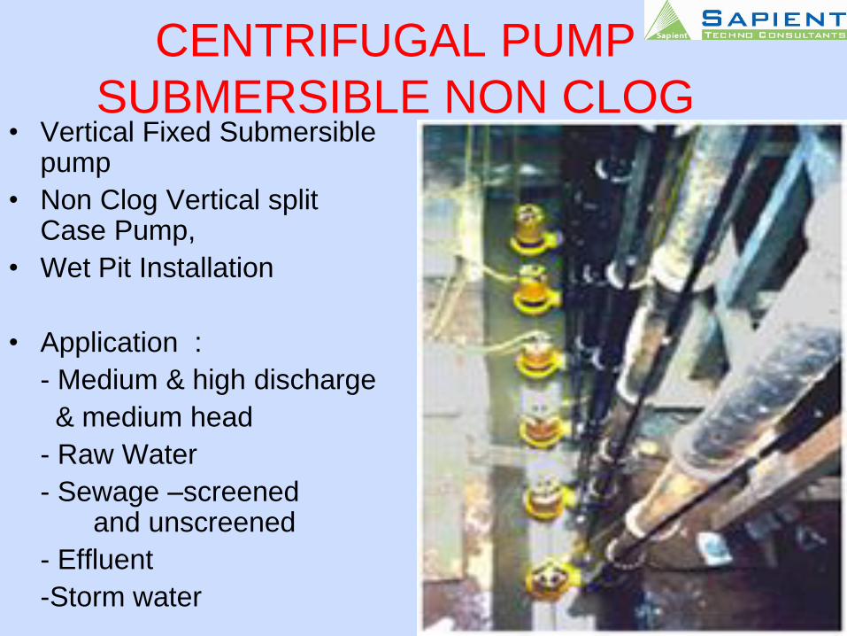
CENTRIFUGAL PUMP
SUBMERSIBLE NON CLOG• Vertical Fixed Submersible
pump
• Non Clog Vertical split Case Pump,
• Wet Pit Installation
• Application :
- Medium & high discharge
& medium head
- Raw Water
- Sewage –screened and unscreened
- Effluent
-Storm water
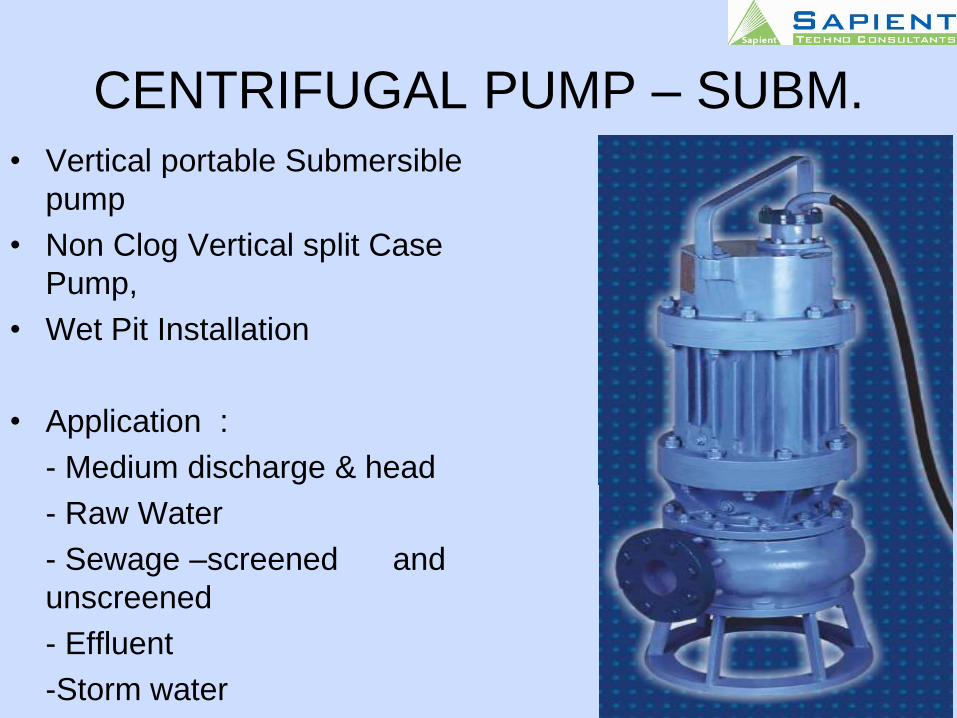
CENTRIFUGAL PUMP – SUBM.
• Vertical portable Submersible
pump
• Non Clog Vertical split Case
Pump,
• Wet Pit Installation
• Application :
- Medium discharge & head
- Raw Water
- Sewage –screened and
unscreened
- Effluent
-Storm water

CENTRIFUGAL PUMP• Vertical Submerged pump
• Non Clog Vertical split Case
• Wet Pit Installation
• Application :
- Medium discharge & head
- Raw Water
- Sewage –screened and
unscreened
- Effluent
-Storm water
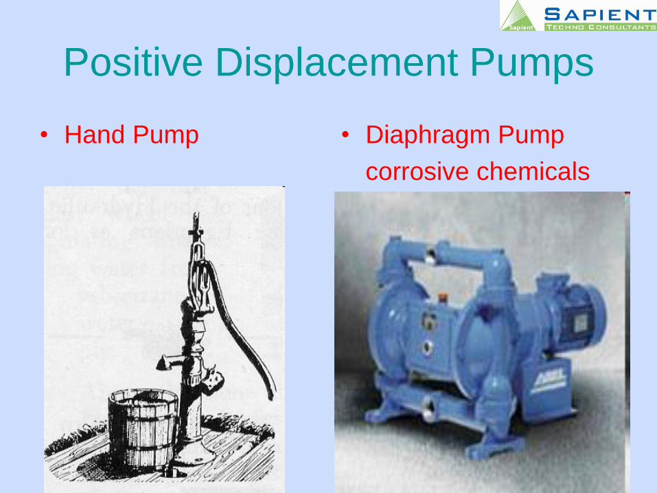
Positive Displacement Pumps
• Hand Pump • Diaphragm Pump
corrosive chemicals
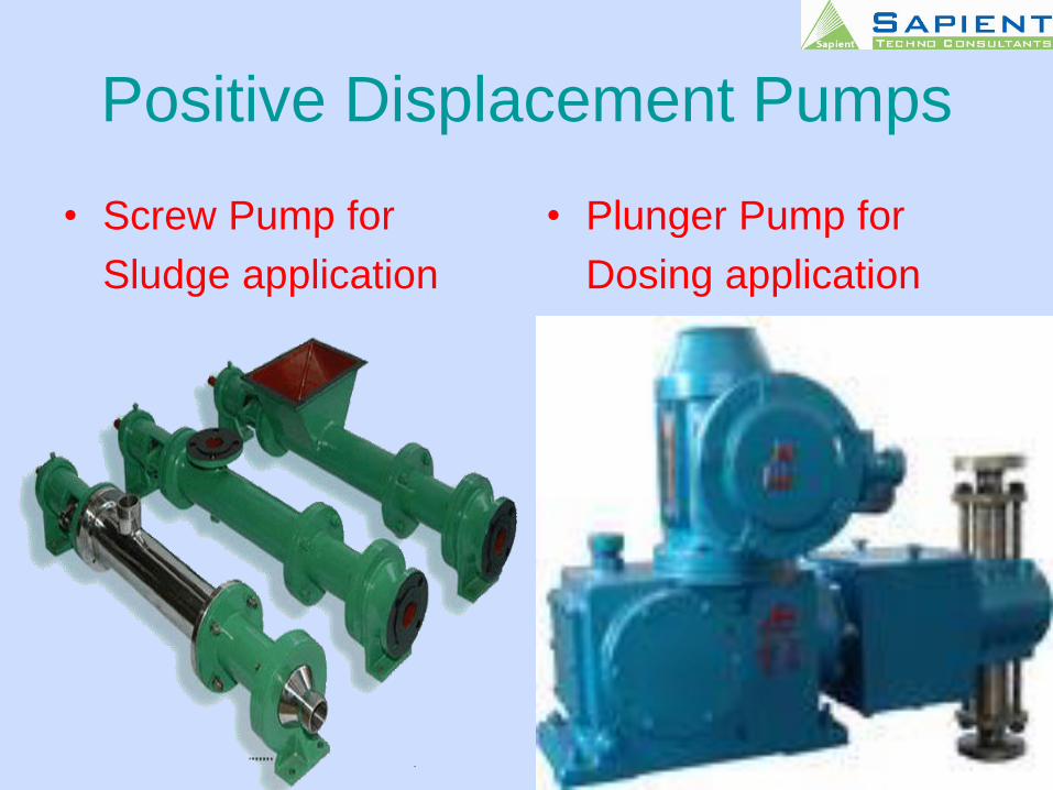
Positive Displacement Pumps
• Screw Pump for
Sludge application
• Plunger Pump for
Dosing application
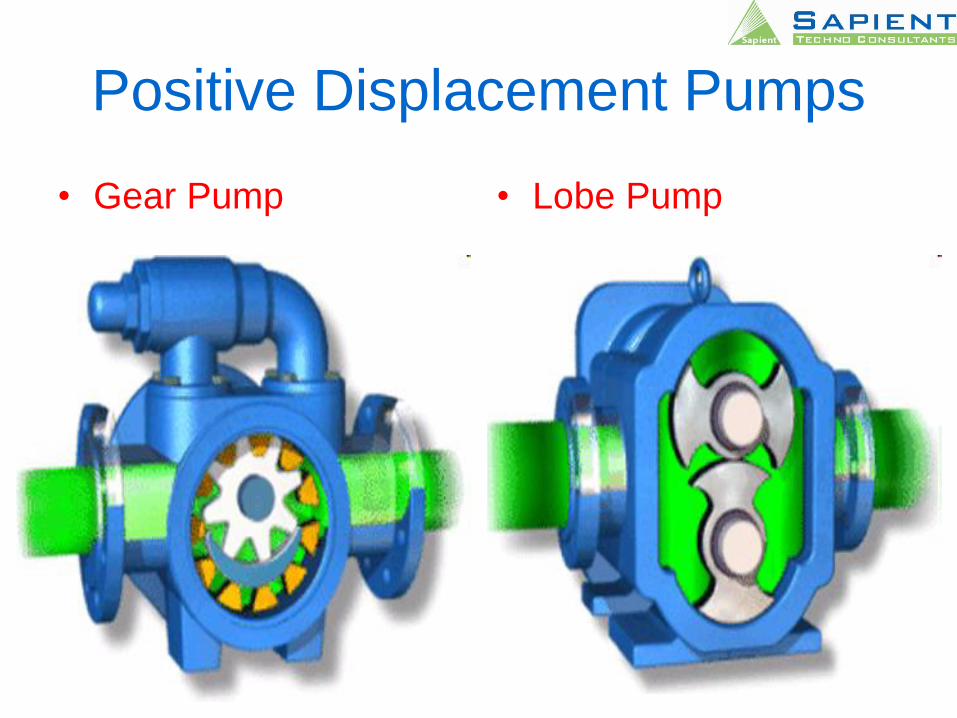
Positive Displacement Pumps
• Gear Pump • Lobe Pump

Positive Displacement Pumps
• Vane Pump • Gear Pump
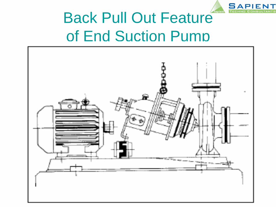
Back Pull Out Feature
of End Suction Pump
INSTALLATION OF PUMPS
• Preparation of Foundation and fixing.
Foundation bolts in pockets.
• Locating pump / base plate on
foundation bolts.
• Leveling of base plate and pump set
using leveling wedges.
• Grouting.
• Alignment.
Foundation• Foundation should be sufficiently substantial to
absorb vibrations and to form permanent, rigid support for the base plate.
• Capacity of the soil or supporting structure should be adequate to withstand the entire load of foundation & dynamic load of pump set
• A sole plate with machined face should be used as a bearing surface.
• Pumps, motors, coupling etc. should be thoroughly cleaned before installation.
• Submersible motors should be filled with water and installed.
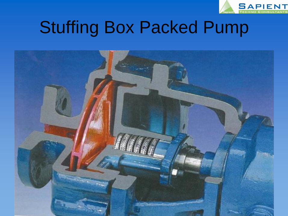
Stuffing Box Packed Pump
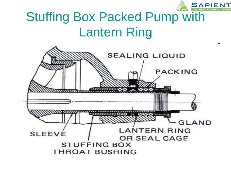
Stuffing Box Packed Pump with
Lantern Ring
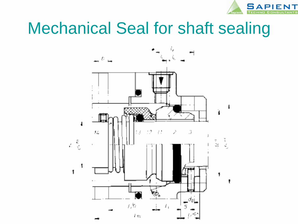
Mechanical Seal for shaft sealing
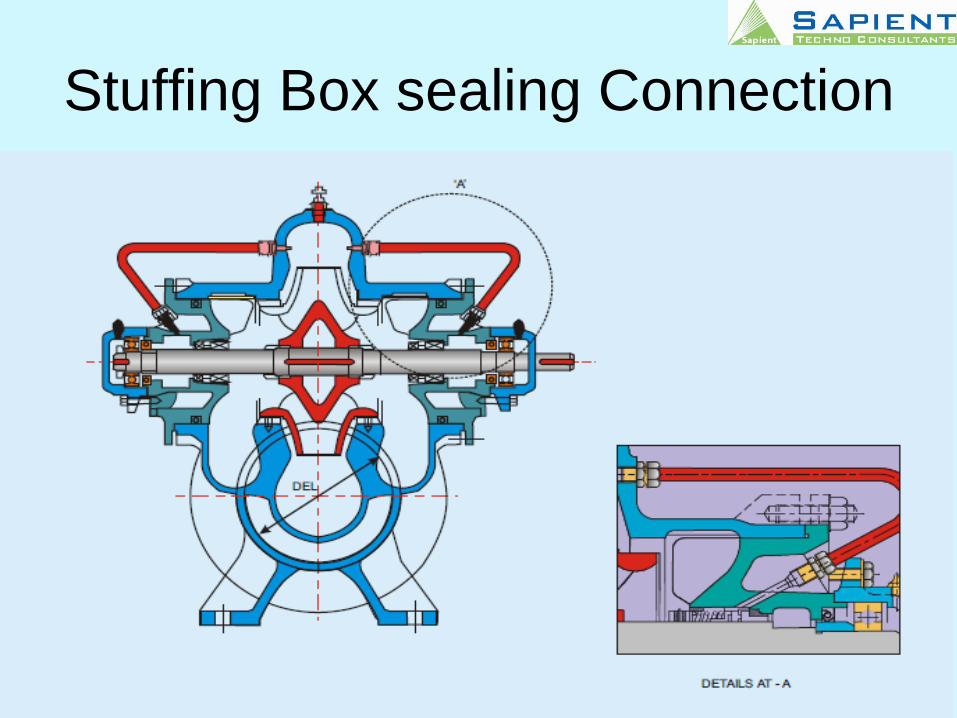
Stuffing Box sealing Connection
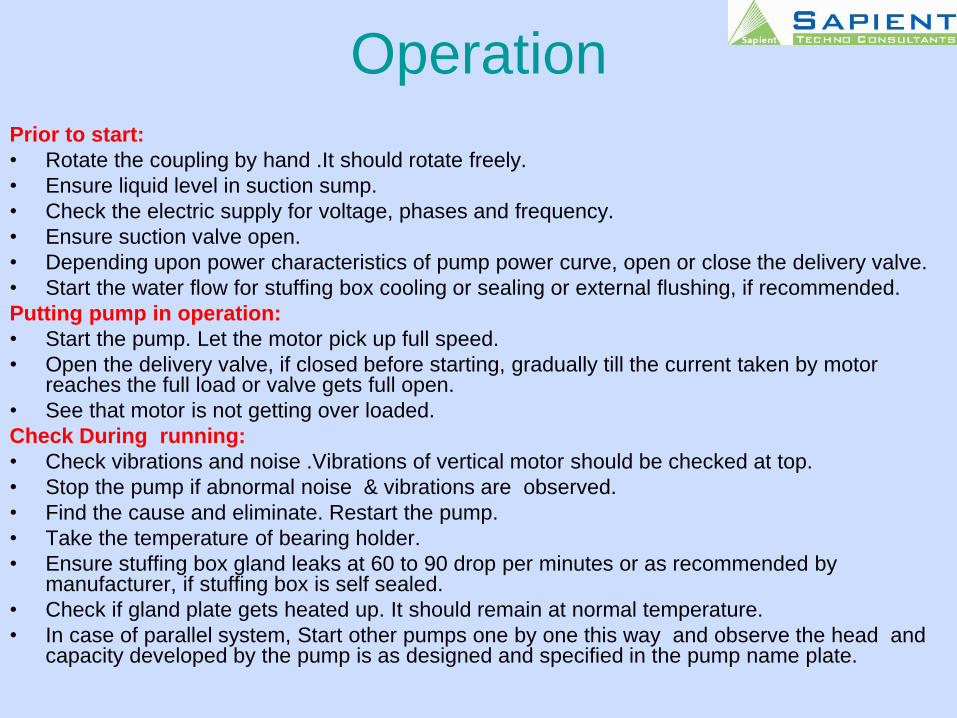
OperationPrior to start:
• Rotate the coupling by hand .It should rotate freely.
• Ensure liquid level in suction sump.
• Check the electric supply for voltage, phases and frequency.
• Ensure suction valve open.
• Depending upon power characteristics of pump power curve, open or close the delivery valve.
• Start the water flow for stuffing box cooling or sealing or external flushing, if recommended.
Putting pump in operation:
• Start the pump. Let the motor pick up full speed.
• Open the delivery valve, if closed before starting, gradually till the current taken by motor reaches the full load or valve gets full open.
• See that motor is not getting over loaded.
Check During running:
• Check vibrations and noise .Vibrations of vertical motor should be checked at top.
• Stop the pump if abnormal noise & vibrations are observed.
• Find the cause and eliminate. Restart the pump.
• Take the temperature of bearing holder.
• Ensure stuffing box gland leaks at 60 to 90 drop per minutes or as recommended by manufacturer, if stuffing box is self sealed.
• Check if gland plate gets heated up. It should remain at normal temperature.
• In case of parallel system, Start other pumps one by one this way and observe the head and capacity developed by the pump is as designed and specified in the pump name plate.
Centrifugal Pump’s Parts
• Casing
• Impeller
• Suction cover & casing cover
• Wear Rings ( Impeller / Casing )
• Shaft
• Shaft sleeve
• Impeller Nut
• Stuffing Box Housing
• Lantern Ring & gland Packing / Mech. Seal
• Water deflector
• Bearing Housing
Preventive Maintenance of Pumps
Maintenance schedules
• Daily Observations:
-Operation timings of each pump.
-Stuffing box leakage condition
-Pump & motor bearing temperatures
-Undue noise or vibrations, if observed
-pressure, flow meter, voltmeter &
current readings.
Preventive Maintenance of Pumps• Half Yearly Inspection
-Check of free movement of stuffing
box gland,
-Cleaning and oiling of gland bolts,
-Inspection of the packing and repacking , if necessary,
-vibration of pump & motor.
-alignment of pump and motor,
-cleaning of oil lubricated bearings and
replenishing fresh oil as recommended by manufacturer,
-checking of grease lubricated bearings and
replenish grease to correct quantity, if needed.
-Check if grease / Lubricating oil overheat the bearings after re-fill.
-Calibration of instruments.
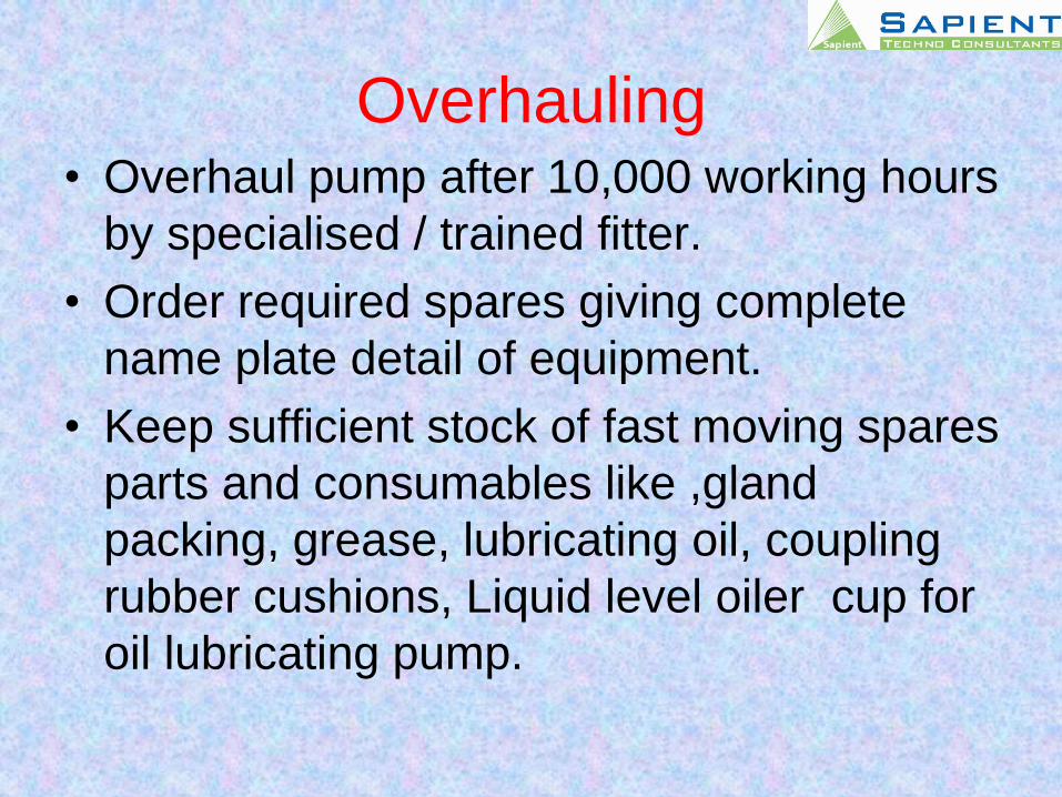
Overhauling• Overhaul pump after 10,000 working hours
by specialised / trained fitter.
• Order required spares giving complete
name plate detail of equipment.
• Keep sufficient stock of fast moving spares
parts and consumables like ,gland
packing, grease, lubricating oil, coupling
rubber cushions, Liquid level oiler cup for
oil lubricating pump.
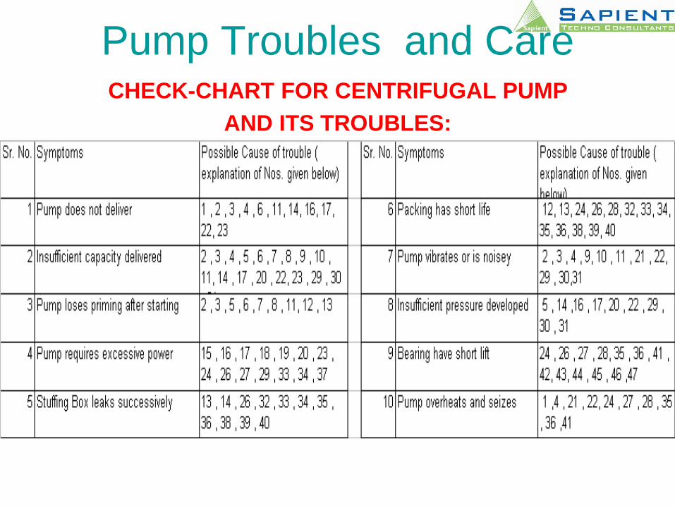
Pump Troubles and CareCHECK-CHART FOR CENTRIFUGAL PUMP
AND ITS TROUBLES:
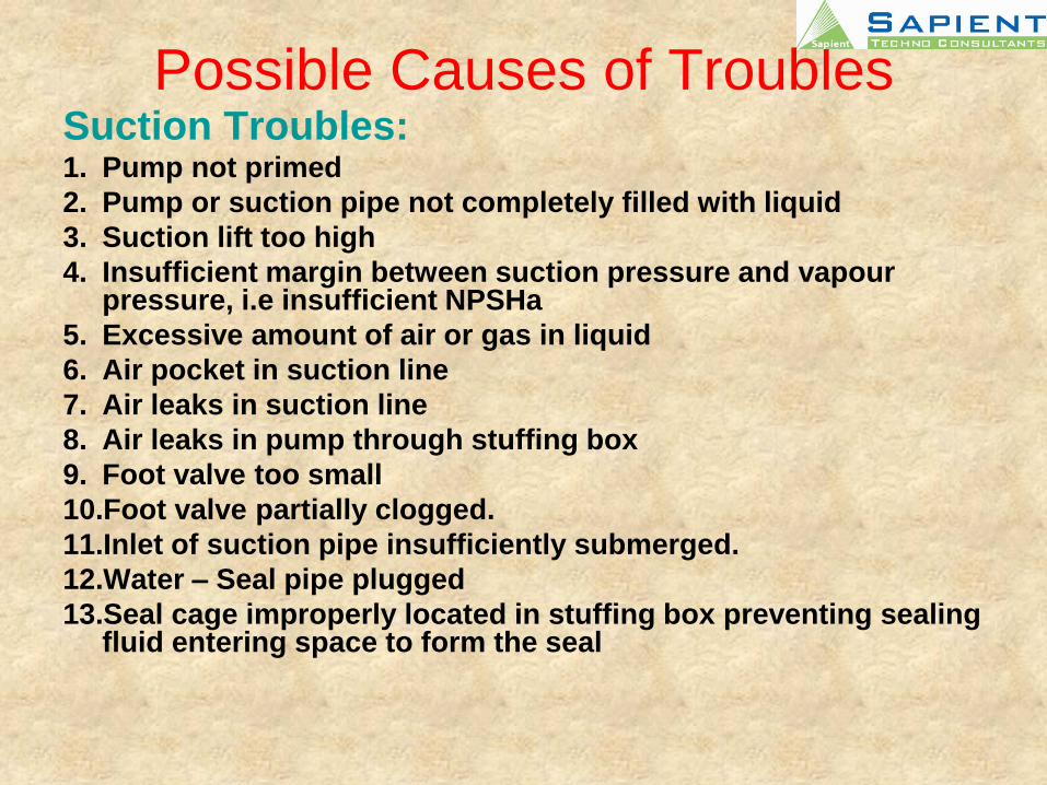
Possible Causes of TroublesSuction Troubles:1. Pump not primed
2. Pump or suction pipe not completely filled with liquid
3. Suction lift too high
4. Insufficient margin between suction pressure and vapour pressure, i.e insufficient NPSHa
5. Excessive amount of air or gas in liquid
6. Air pocket in suction line
7. Air leaks in suction line
8. Air leaks in pump through stuffing box
9. Foot valve too small
10.Foot valve partially clogged.
11.Inlet of suction pipe insufficiently submerged.
12.Water – Seal pipe plugged
13.Seal cage improperly located in stuffing box preventing sealing fluid entering space to form the seal
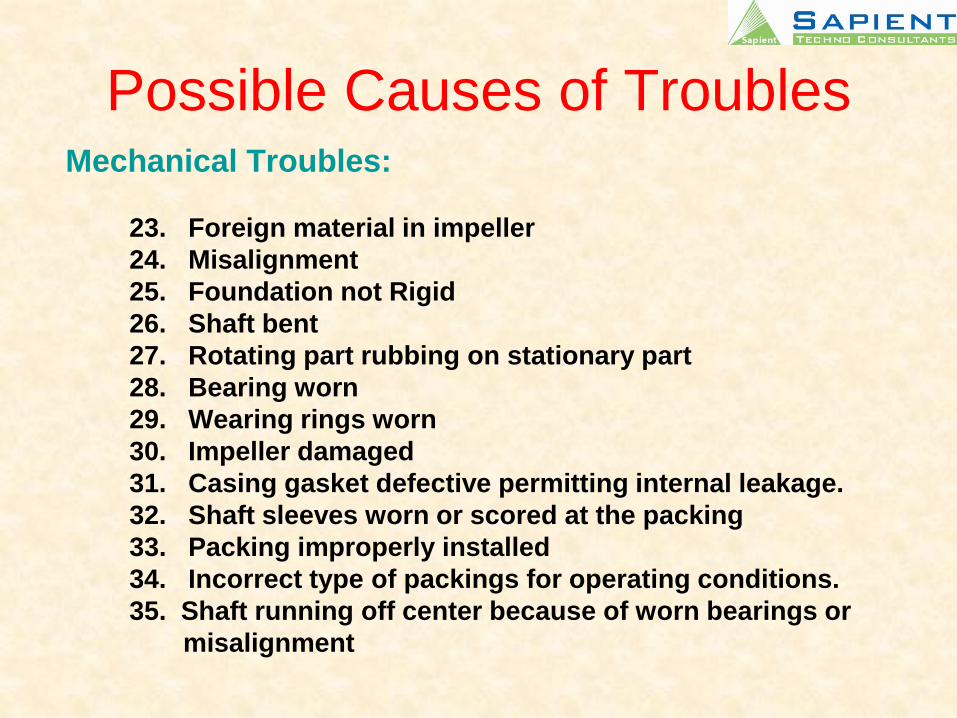
Possible Causes of TroublesMechanical Troubles:
23. Foreign material in impeller
24. Misalignment
25. Foundation not Rigid
26. Shaft bent
27. Rotating part rubbing on stationary part
28. Bearing worn
29. Wearing rings worn
30. Impeller damaged
31. Casing gasket defective permitting internal leakage.
32. Shaft sleeves worn or scored at the packing
33. Packing improperly installed
34. Incorrect type of packings for operating conditions.
35. Shaft running off center because of worn bearings or
misalignment
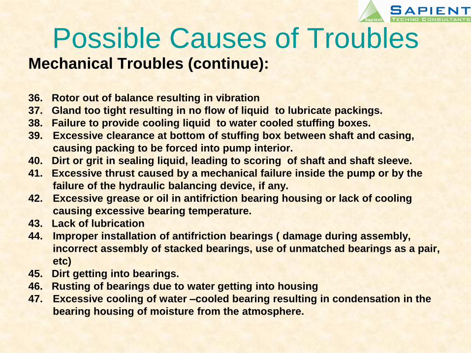
Possible Causes of TroublesMechanical Troubles (continue):
36. Rotor out of balance resulting in vibration
37. Gland too tight resulting in no flow of liquid to lubricate packings.
38. Failure to provide cooling liquid to water cooled stuffing boxes.
39. Excessive clearance at bottom of stuffing box between shaft and casing,
causing packing to be forced into pump interior.
40. Dirt or grit in sealing liquid, leading to scoring of shaft and shaft sleeve.
41. Excessive thrust caused by a mechanical failure inside the pump or by the
failure of the hydraulic balancing device, if any.
42. Excessive grease or oil in antifriction bearing housing or lack of cooling
causing excessive bearing temperature.
43. Lack of lubrication
44. Improper installation of antifriction bearings ( damage during assembly,
incorrect assembly of stacked bearings, use of unmatched bearings as a pair,
etc)
45. Dirt getting into bearings.
46. Rusting of bearings due to water getting into housing
47. Excessive cooling of water –cooled bearing resulting in condensation in the
bearing housing of moisture from the atmosphere.
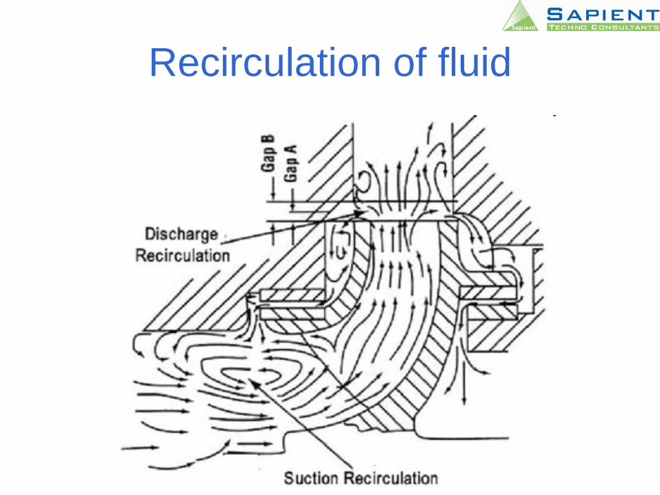
Recirculation of fluid
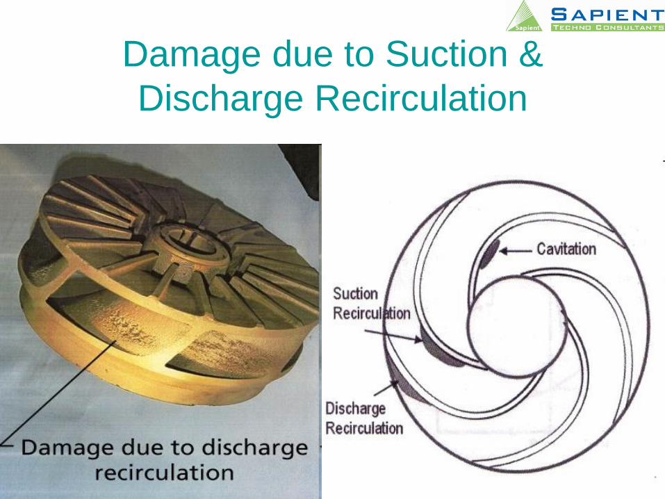
Damage due to Suction &
Discharge Recirculation
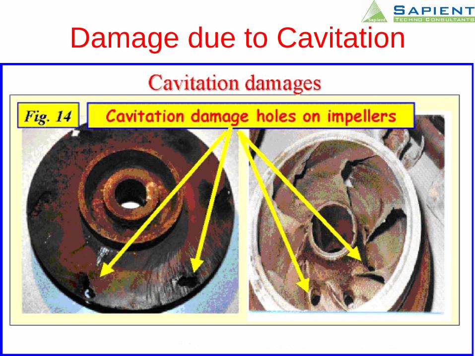
Damage due to Cavitation
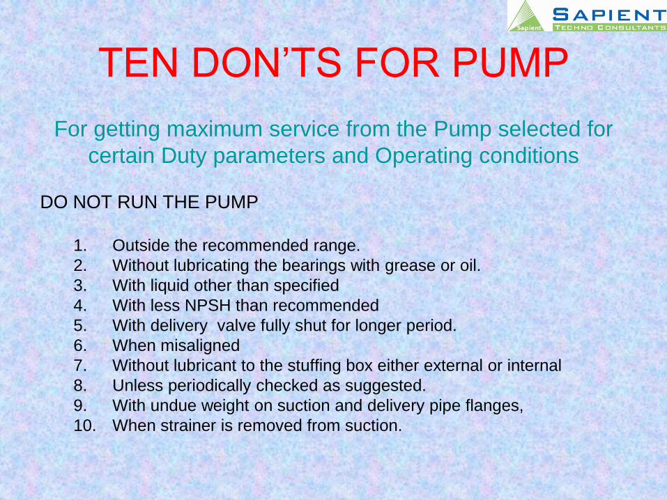
TEN DON’TS FOR PUMP
For getting maximum service from the Pump selected for
certain Duty parameters and Operating conditions
DO NOT RUN THE PUMP
1. Outside the recommended range.
2. Without lubricating the bearings with grease or oil.
3. With liquid other than specified
4. With less NPSH than recommended
5. With delivery valve fully shut for longer period.
6. When misaligned
7. Without lubricant to the stuffing box either external or internal
8. Unless periodically checked as suggested.
9. With undue weight on suction and delivery pipe flanges,
10. When strainer is removed from suction.

Thank You