waves two special phase relationships between waves are a)wave forms in phase b) waveforms that are...
TRANSCRIPT

Waves • Two special phase relationships between waves
are• a)Wave forms in phase• b) Waveforms that are out of phase

• Wavefronts are equidistant lines (straight or curved) each of which joins crests on different waves that are travelling together in phase.
• Waveforms can be represented in a more simple form by using wavefronts
• The linear distance between adjacent wavefronts represents the wavelength (λ) of the waves
• Rays are lines drawn perpendicular through the wavefronts …indicates the direction of the wave
• Parallel waves require plane or straight wavefronts to represent them (with parallel rays)
• Circular wavefronts represent waves that radiate from a point sources to produce concentric circles…these have divergent rays

Waves can be:
• Reflected- λ1 > λ2
- f remains constant- v1 > v2
- n = λ1 /λ2 =v1 / v2 = sin i / sin r
• Refracted - occurs when a wave passes from one medium to another in which it has a different speed and wavelength and the angle of incidence at the boundary between the media is NOT zero
- Generally for any type of wave (water, light, sound etc.)- Wavelength is greater in less dense medium- Speed is greater in less dense medium- Refraction occurs towards the normal in the denser medium and away from the
normal in the less dense medium - For the denser medium:n = wavelength / speed of waves in the less dense medium
wavelength /speed of waves in denser medium
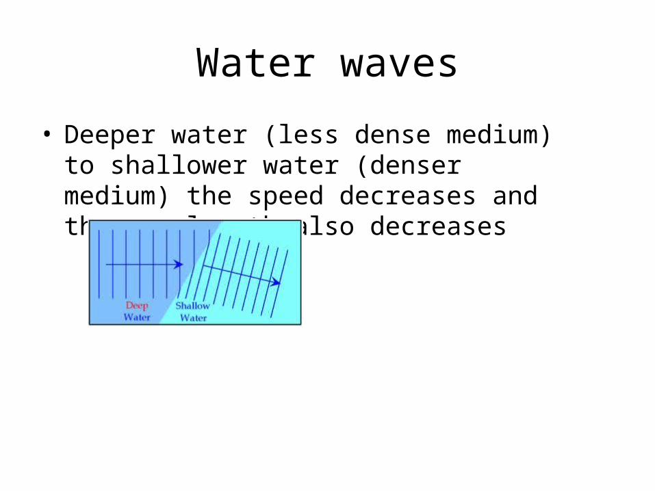
Water waves
• Deeper water (less dense medium) to shallower water (denser medium) the speed decreases and the wavelength also decreases

• Diffracted – diffraction is the spreading of waves as they pass through the edge of an obstacle or as they pass through a aperture or opening (such as a slit or a gap) the width (a) of which is comparable with or less than the wavelength, λ of the waves
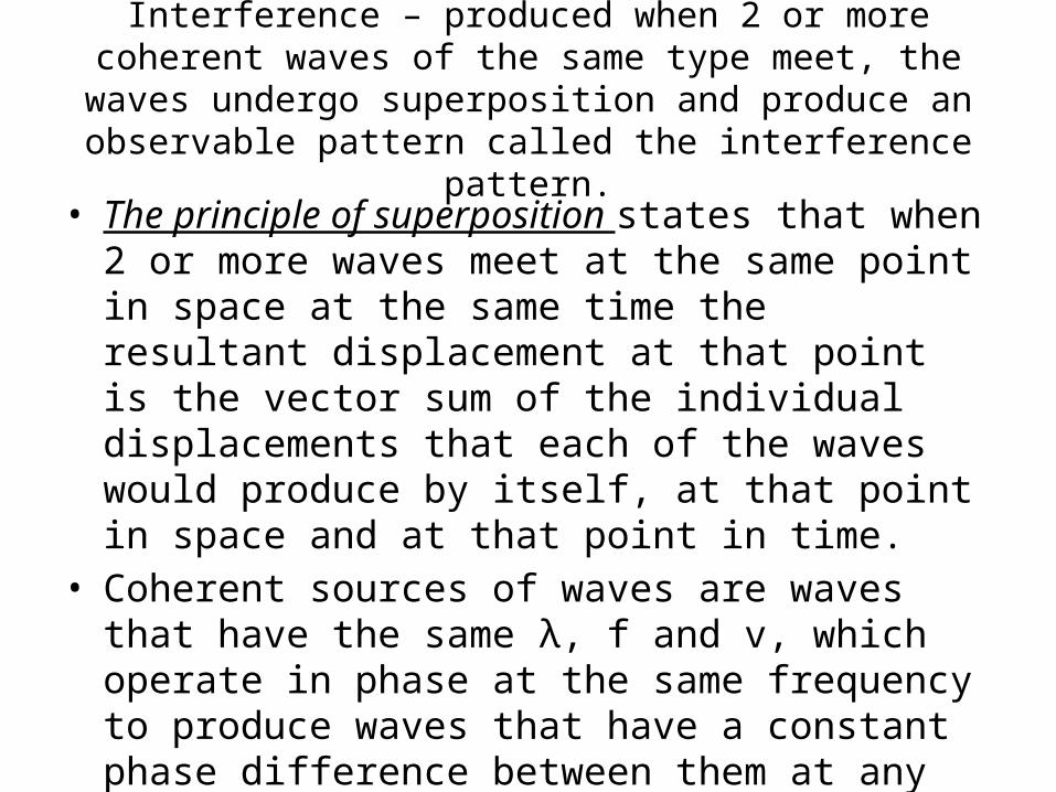
Interference – produced when 2 or more coherent waves of the same type meet, the waves undergo superposition and produce
an observable pattern called the interference pattern.
• The principle of superposition states that when 2 or more waves meet at the same point in space at the same time the resultant displacement at that point is the vector sum of the individual displacements that each of the waves would produce by itself, at that point in space and at that point in time.
• Coherent sources of waves are waves that have the same λ, f and v, which operate in phase at the same frequency to produce waves that have a constant phase difference between them at any point where they meet.
• For interference, if there is a resultant wave, it has the same f, λ and v as the interfering coherent waves.
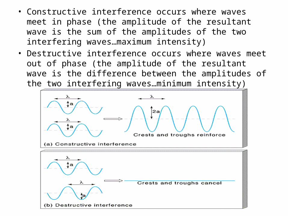
• Constructive interference occurs where waves meet in phase (the amplitude of the resultant wave is the sum of the amplitudes of the two interfering waves…maximum intensity)
• Destructive interference occurs where waves meet out of phase (the amplitude of the resultant wave is the difference between the amplitudes of the two interfering waves…minimum intensity)

Interference patterns• When two coherent sources overlap and interference pattern is
created such as when a source is divided using a double slit (Young’s double slit)
• A fringe pattern is produced on a screen (alternating bright – constructive interference and dark – destructive interference bands or fringes)
• x = (λD)/dD- linear distance between the double slits and the screend- the slit separation (linear distance between the separation of the two
slits)λ – the wavelength of the light wavesx- the fringe separation (linear distance between the centres of the
adjacent bright fringes or dark fringes


Sound waves• Produced and propagated by the vibrations (i.e. oscillations)
of the particles of a material medium…eg. A loud speaker core, tuning forks prongs, drum skins, guitar strings, air in trumpets, trombones, flutes, pipes, etc.
• They are longitudinal, mechanical waves• Propagated in the medium in which they travel by a series of
compressions and rarefractions• Can be regarded as displacement waves and as pressure
waves

Properties of sound waves• Cannot travel in a vacuum…requires a medium to travel• Travels fastest in solids and slowest in gases• Obeys the laws of reflection…an echo• Hard surfaces better reflect it, soft surfaces better absorb it• Concave surfaces bring waves to a focus, convex spreads them out• If echo time is too short, overlap occurs with original sound …drawn
out sound (Reverberation)• Obeys the laws of refraction : sound waves bend towards cooler
regions (denser) and away from warmer regions• Can be diffracted – since usually larger wavelengths…easily diffracted• Can show interference effects• Wave equation v = fλ can be applied• Speed in a given medium for sound waves depends on the temperature
of that medium• Speed can be determined using reciprocal firing or echo method
• Sound waves can be subjected to situations of critical angle and total internal reflection
Refractive index, n= wavelength or speed of a wave in less dense medium wavelength or speed of a wave in a more dense medium
ELECTROMAGNETIC WAVES• Name given to a range of waves having different wavelengths, frequencies
and energies but some common properties• All are propagated by varying electric and magnetic fields which oscillate
at right angles to one another and also to the direction of propagation of the wave
• All travel with the same constant speed in air or a vacuum…the speed of light…3.0x10⁸ ms-1
• All are unaffected by external electric and magnetic fields• All are transverse waves• All can undergo reflection, refraction, diffraction and interference • All travel in straight lines in a vacuum or air or other medium• All can be plane polarized• All are progressive waves but can produce stationary waves under suitable
circumstances• The intensity of each varies inversely as the square of the linear distance
from a point source

Electromagnetic spectrum is divided into the following range with specific range of 300nm (violet light) to 750nm (red light)
Light has a wave-particle nature: Wave nature supported by the young double slit experiment that light can be Diffracted and interference can occur andThe Photoelectric effect ( instantaneous emission of electrons from the surfaces ofcertain material when exposed to E.M. radiation above a certain frequency

Wave-particle duality
According to the particle theory:• Light travels faster in a denser medium • It does not undergo diffraction and interference• Explains the photoelectric effect (instantaneous
emission of electrons from a solid liquid or gas when it absorbs energy from light)
Wave theory:• Light travels faster in a less dense medium (Foucault)• It undergoes diffraction and interference (young’s
double slit experiment)
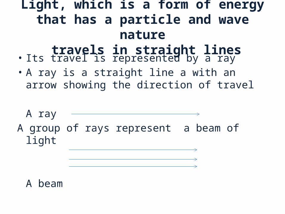
Light, which is a form of energy that has a particle and wave nature travels in straight lines
• Its travel is represented by a ray• A ray is a straight line a with an arrow showing the
direction of travel
A rayA group of rays represent a beam of light
A beam

There are three main types of beams of light:• Parallel beams• Convergent beams• Divergent beamsUse your dictionary to write down the meanings
of 1) Parallel ______________________________2) Convergent ___________________________3) Divergent ____________________________
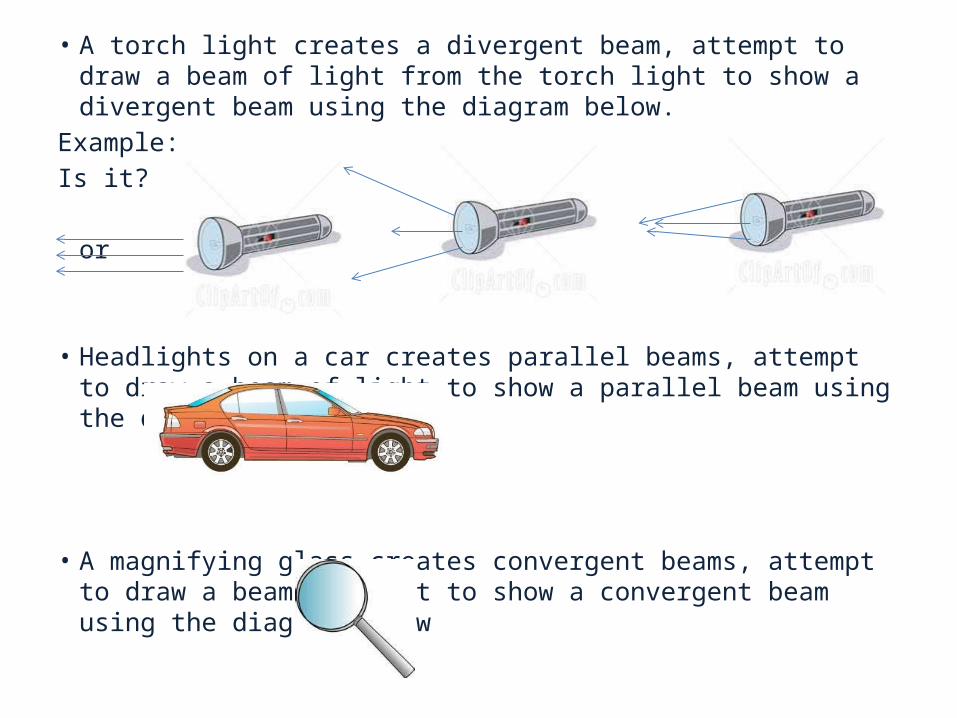
• A torch light creates a divergent beam, attempt to draw a beam of light from the torch light to show a divergent beam using the diagram below.
Example:Is it?
or or
• Headlights on a car creates parallel beams, attempt to draw a beam of light to show a parallel beam using the diagram below
• A magnifying glass creates convergent beams, attempt to draw a beam of light to show a convergent beam using the diagram below
Properties
• Rectilinear propagation – it travels in straight lines observed in shadow formation (eg. Eclipse) and image formation (pin hole camera)
• Reflection of light – formation of images eg. In mirrors
• Refraction of light – observed when rectangular and triangular prisms, and lenses are used
• Dispersion of light – rainbow formation
Shadows, are formed when an opaque object is placed in front of the path of light. They can be
formed using • Using a point source – which is a small light source such as a
torch light
• Or an extended source – which is a large light source such as the sun

Solar eclipse
• When the moon passes between the sun and the Earth
• The moon fully or partially covers the view of the sun from the Earth
• The partially covered view is the area of the penumbra
• The fully covered view is the area of the umbra.

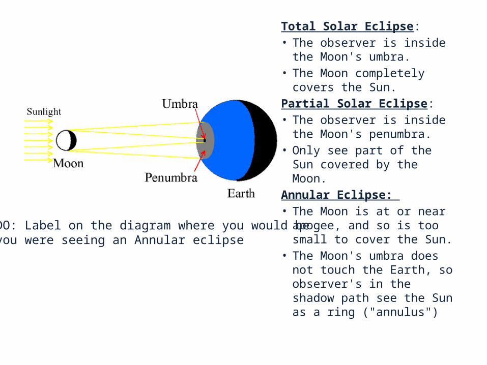
Total Solar Eclipse: • The observer is inside the
Moon's umbra. • The Moon completely covers
the Sun. Partial Solar Eclipse: • The observer is inside the
Moon's penumbra. • Only see part of the Sun
covered by the Moon. Annular Eclipse: • The Moon is at or near
apogee, and so is too small to cover the Sun.
• The Moon's umbra does not touch the Earth, so observer's in the shadow path see the Sun as a ring ("annulus")
TO DO: Label on the diagram where you would beif you were seeing an Annular eclipse
Lunar Eclipse
A lunar eclipse occurs when the moon passes behind the Earth and is blocked by Earth (the Earth acts as the opaque object)
• TO DO: Draw a diagram of the Sun, Earth and Moon in a lunar eclipse position
Luminous versus non-luminous
• If you are given the definition that luminous objects produce it own light and non-luminous objects reflect light, make a list of at least five objects that are luminous and non-luminous objects
Luminous objects Non luminous objects

And you are given the definition that:• Transparent objects allow all light to pas through it• Translucent objects allow some light to pass through
it• Opaque objects do not allow any light to pass
through it• Complete the table below with at least five items you
see dailyTransparent objects Translucent Opaque
Glass Frosted glass A wall
Reflection of Light Light incident on a surface may •Absorbed – material is opaque, dark, dull or rough•Transmitted/refracted – surface is transparent or translucent•Reflection – surface is bright, smooth shiny. The “bouncing” of light off of a surface occurs. The light does not pass through the surface (called a medium)

Reflection
• One law of reflection is that the incident ray, the reflected ray and the normal all lie in the same plane

Reflection• Another law of reflection is that the angle of
incidence is equal to the angle of reflection. For example if the incident ray “hits” the mirror at 45°, then the reflected ray bounces off the mirror at a 45° angle. (° - this is the degree symbol)

Reflection
An image formed in a (plane) mirror is • not real (it is called Virtual)• It is the same distance it is from the front of
the mirror as the back of the mirror• It is upright
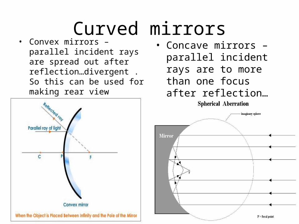
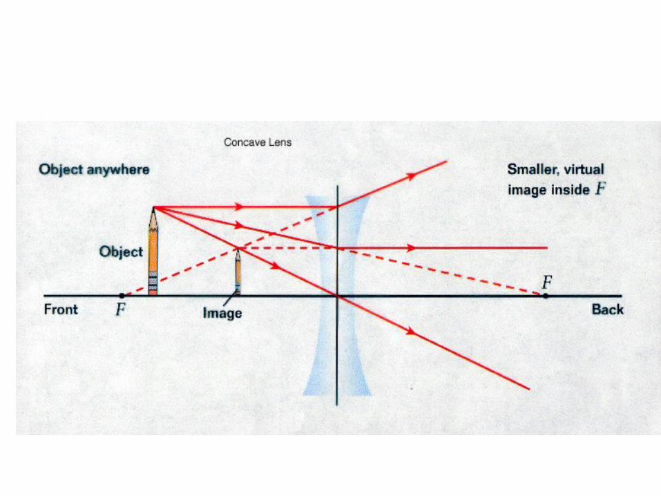
Curved mirrors• Convex mirrors – parallel incident
rays are spread out after reflection…divergent . So this can be used for making rear view mirrors since it gives a wide field of view (Principle of reversibility)
• Concave mirrors – parallel incident rays are to more than one focus after reflection…converge

• The diagram presented below in Figure 4 illustrates the reflection patterns obtained from both concave and convex mirrors. The concave mirror on the left has a reflecting surface that curves inwards that resembles a portion of the interior of a sphere. When light rays that are parallel to the principal, or optical axis, reflect from the surface of a concave mirror, in this case, the rays leading from the soldier's hat and feet, they converge on the focal point in front of the mirror. The distance from the reflecting surface to the focal point is termed the mirror's focal length. The size of the image depends upon the distance of the object from the mirror and it's position with respect to the mirror's surface. In this case, the soldier is placed at the center of curvature and the reflected image is upside down and in front of the mirror's center of curvature.
• The convex mirror on the right-hand side of Figure 4, however, has a reflecting surface that curves outward, which resembles a portion of the exterior of a sphere. Light rays parallel to the optical or principal axis are reflected from the surface in a manner that diverges from a focal point that is behind the mirror. Images formed with convex mirrors are always right side up and reduced in size. These images are also termed virtual images because when they occur reflected rays appear to diverge from a focal point behind the mirror.

Parabolic mirror

Images in a plane mirror
dev.physicslab.org
Characteristics of an image
• Virtual image – cannot be produced on a screen• Real image – can be produced on a screen• Image distance (v) is equal to object distance
(u)• Image has the same size as the object
(magnification= 1)• Image is erect/laterally inverted with respect to
the object


• Optical centre of the lens: a point on the axis of a lens that is so located that any ray of light passing through it in passing through the lens suffers no net deviation and that may be within, without, or on either surface of the lens
• Principal Axis – line which passes through the optical centre of the lens• First Principal Focus (F1) : It is that point on the principal axis of the lens, the
rays starting from which (convex lens) or appear to converge at which (concave lens) become parallel to principal axis after refraction from the lens.
• Focal plane : Line perpendicular to the principal axis that passes through the Principal Focus
• Thicker lenses bend light more, and are therefore described as more powerful. Powerful lenses have short focal lengths. The power of a lens is measured in dioptres(D) and is given by the formula:
Power = 1 focal length (m)

• The lens formula is: 1 = 1 + 1
f u v[f - focal length; u - object distance; v - image distance]• The magnification M = v
uSince v is in metres, and u is in metres, M has no units.
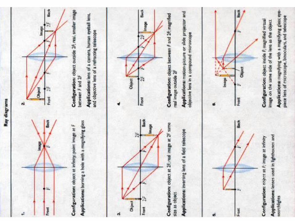

Ray DiagramsWe can determine where an image lies in relation to the objects by using a ray diagram. We can do this by using two simple rules:• Draw a ray from the top of the image parallel to the principal axis. This ray bends at the lens axis and goes through
the principal focus.• Draw a ray from the top of the lens through the centre of the lens.• Where the two rays meet, that is where the image is found. In this example, we have placed the object
between F and 2F. The diagrams show how we do a ray diagram step-by-step:• • Step 1. Draw the ray parallel to the principal axis.
•
• Step 2. Draw the refracted ray so that it passes through the principal focus.
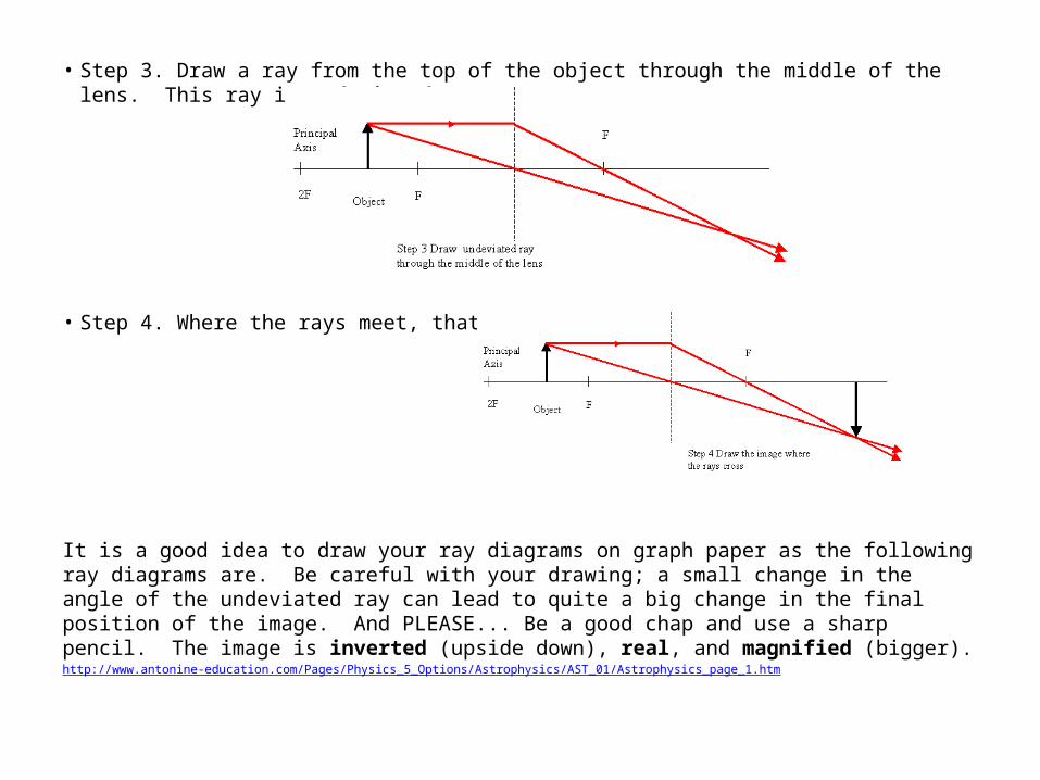
• Step 3. Draw a ray from the top of the object through the middle of the lens. This ray is undeviated.
• Step 4. Where the rays meet, that is where the image is.
It is a good idea to draw your ray diagrams on graph paper as the following ray diagrams are. Be careful with your drawing; a small change in the angle of the undeviated ray can lead to quite a big change in the final position of the image. And PLEASE... Be a good chap and use a sharp pencil. The image is inverted (upside down), real, and magnified (bigger).http://www.antonine-education.com/Pages/Physics_5_Options/Astrophysics/AST_01/Astrophysics_page_1.htm
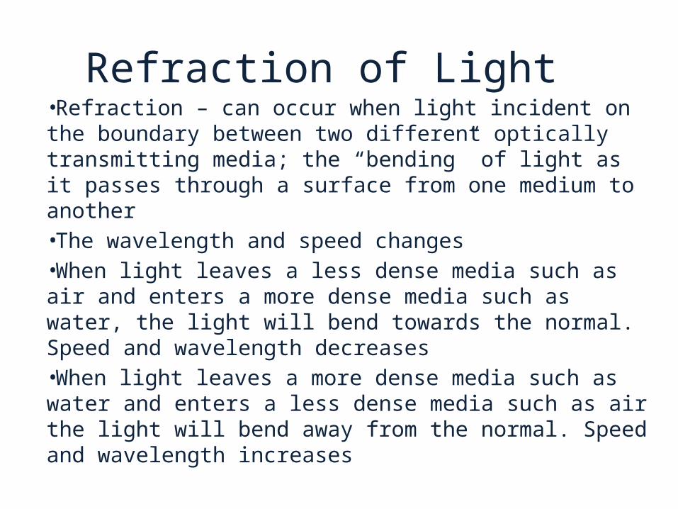
Refraction of Light •Refraction – can occur when light incident on the boundary between two different optically transmitting media; the “bending” of light as it passes through a surface from one medium to another•The wavelength and speed changes•When light leaves a less dense media such as air and enters a more dense media such as water, the light will bend towards the normal. Speed and wavelength decreases •When light leaves a more dense media such as water and enters a less dense media such as air the light will bend away from the normal. Speed and wavelength increases

i
r
Air – less dense than water
Water
Dotted line – Imaginary called the normal
i – called the angle of incidencer – called the angle of refraction
This happens for example when a straw is put into a glass of water, it looks bent
The ray of light bends towards the normal
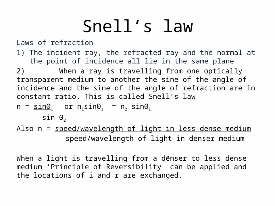
Snell’s lawLaws of refraction1) The incident ray, the refracted ray and the normal at the point of
incidence all lie in the same plane2) When a ray is travelling from one optically transparent medium to another the sine of the angle of incidence and the sine of the angle of refraction are in constant ratio. This is called Snell’s lawn = sinϴ1 or n1sinϴ1 = n2 sinϴ1
sin ϴ2
Also n = speed/wavelength of light in less dense medium speed/wavelength of light in denser medium
When a light is travelling from a denser to less dense medium ‘Principle of Reversibility” can be applied and the locations of i and r are exchanged.

• Rectangular block • Triangular prism
Critical Angle
The critical angle, c is that angle of incidence in the denser medium that produces an angle if refraction of 90° in the less dense mediumn = _1_
sincIf the angle of incidence in the denser medium is greater than increased beyond the critical angle • Then total internal reflection occurs• Happens when: i) rays/waves are travelling from a more dense to a less dense mediumii) The angle of incidence in the denser medium is greater than the critical angle

Some examples when critical angle is surpassed
Rays enter Isosceles triangular prismIncident 90 ° on one of the equal sides
Rays enter Isosceles triangular prismIncident 90 °on base
Rays enter Isosceles triangular prismIncident 45°on one of the equal sides
Pictures: http://www.physicstutorials.org/home/optics/refraction-of-light/critical-angle-and-total-reflection