wavistrong - future pipe industries...• wavistrong installation guide for gre pipe systems. 3...
TRANSCRIPT

ASSEMBLY INSTRUCTIONSREKA SEALED LOCK JOINT (REKA SLJ)
WAVISTRONG®


3
WAVISTRONG®
Assembly InstructionsREKA Sealed Lock Joint (REKA SLJ)
WAVISTRONG®
Assembly InstructIonsreKA seAled locK JoInt (reKA slJ)
Ws tcd 037(Gb) rev. 0 20170501Issue date: 24 April 2017

4
WAVISTRONG®
Assembly InstructionsREKA Sealed Lock Joint (REKA SLJ)

1
WAVISTRONG®
Assembly InstructionsREKA Sealed Lock Joint (REKA SLJ)
Table of ConTenTs
1 General 1.1 Joint overview
2 referenCes
3 HealTH and safeTy
4 QualiTy
5 inspeCTion
6 MaTerials, Tools and ConsuMables6.1 materials6.2 tools6.3 consumables
7 asseMbly proCedure7.1 step 1: Prepare the assembly7.2 step 2: Install the reKA seal7.3 step 3: Insert the spigot7.4 step 4: Insert the locking strip7.5 step 5: stretch and align the joint
8 sToraGe Guidelines for rubber seals, loCkinG sTrips and lubriCanT
annex a – perMiTTed anGular defleCTions
annex b – MeasurinG anGular defleCTion in THe field
annex C – rubber seal diMensions
annex d – loCkinG sTrip diMensions
annex e – insTallaTion TiMe
annex f – JoinT disasseMbly
33
5
5
5
5
6666
6789
1011
12
13
14
15
16
17
18

2
WAVISTRONG®
Assembly InstructionsREKA Sealed Lock Joint (REKA SLJ)

3
WAVISTRONG®
Assembly InstructionsREKA Sealed Lock Joint (REKA SLJ)
1 General
this document describes the method to assemble the reKA sealed lock Joint (reKAslJ).
to ensure that the performance of the installed joint complies with the requirements used for the design, it is essential that all personnel involved in the bonding procedure is familiar with and fully understands the techniques described in this document.
the instructions in this document are as complete as possible. However, it is not possible to describe all circumstances that might be encountered in the field. therefore, our experienced supervisors can opt for an alternative method in order to achieve an optimum solution, using the latest techniques, methods and insights.
besides, our supervisors may be consulted for clarification of statements made in this document and for advice about specific problems encountered in the field.
definition of words used in these instructions:• theword“shall”indicatesarequirement;• theword“should”indicatesarecommendation.
1.1 Joint overviewthe reKAslJ is a mechanically locked joint, sealed by means of a rubber seal housing in the socket end (a so-called reKA seal). It comes in two types:• TypeA,usingonelockingstrip;and• TypeB,usingtwolockingstrips.
reKAslJ type A reKAslJ type b

4
WAVISTRONG®
Assembly InstructionsREKA Sealed Lock Joint (REKA SLJ)
Pipe with integral socket end Pipe with spigot end
Rubber seal Locking strip
Locking strip insertion hole
reKAslJ type A overview
reKAslJ type b overview

5
WAVISTRONG®
Assembly InstructionsREKA Sealed Lock Joint (REKA SLJ)
2 referenCes
these instructions are part of the overall Wavistrong pipe system. As such the following documents, and the references therein, apply.•WavistrongInstallationGuideforGREPipeSystems.
3 HealTH and safeTy
When working with Gre products, following safety precautions shall be taken:• Wearsuitableprotectiveclothingatalltimes• UsePersonnelProtectiveEquipment(PPE),suchas:
- long sleeves- Hard hat, if required by site conditions- safety shoes- Glasses- Gloves, for mechanical and chemical protection- For health and safety data reference is made to the applicable instructions (see section 2)
4 QualiTy
It is advised that the bonder possesses a valid Jointer Qualification certificate, issued by the pipe manufacturer or a Qualified certifier.
5 inspeCTion
All pipes, fittings or components used in the pipeline system shall be inspected for damages, prior to the actual jointing activity. Pay special attention to anything that might damage the seal and might result in a leaking joint. rejected items shall be separated and quarantined from undamaged materials to avoid unintentional use.
make sure that storage of rubber seals, locking strips and lubricant complies with the storage requirements.ensure all necessary tools and materials are available.
take notice of the safety precautions stated in this document and those in the referenced instructions.

6
WAVISTRONG®
Assembly InstructionsREKA Sealed Lock Joint (REKA SLJ)
6 MaTerials, Tools and ConsuMables
the following materials, tools and consumables are needed during the installation.
6.1 Materials• REKArubberseal*• Lockingstrip,oneortwodependingonjointtype*• Lubricant*
*tobesuppliedbyFuturePipeIndustries.
6.2 Tools• Tworubberlinedpipeclamps• Chaintackles
- For pipe Id ≤ 500 mm: pulling force capability of 750 kg- For pipe Id > 500 mm: pulling force capability of 1500 kg
• Plasticorwoodenhammer,orpneumatichammer• Digitallevelindicator• Stringlineofatleast30meterlength• Waterproofmarker• Measuringtapeand/orfoldingrule• Verniercalliper
6.3 Consumables• Nonfluffycleanrags• Plasticsheets• Mixingspatula• Ducttape• Cleanwater• Safetyequipment(seeSection3
7 asseMbly proCedure
the reKAslJ requires a specific but straightforward way of assembling, split into the following five overarching steps.1. Prepare the assembly.2. Install the reKA seal.3. Insert the spigot.4. Insert the locking strip.5. stretch and align the joint.
before starting the installation, the following shall be insured.• Forundergroundpipelines,thetrenchingshallbereadyandshallmeetthesystemrequirementsonbeddingandcompaction,
and shall be within the joint approved and project specified angular deflections.• For above ground pipe systems, the supporting shall be performed as specified by the design engineer or as per the
project-specific method statement, and shall be within the joint approved and project specified angular deflections.

7
WAVISTRONG®
Assembly InstructionsREKA Sealed Lock Joint (REKA SLJ)
7.1 step 1: prepare the assemblya) position the holes of locking strip such that they are easily
accessible. this guarantees easy insertion of the locking strip for both
the current and the next joint. At this position, place a mark at thecrownof thespigotend indicating“thisside top”.From this point onwards, do not rotate the pipe during any stage of the assembly process and always maintain the mark at the top side.
b) remove sand and dirt from the joint area. obtain sufficient clearance from the soil during the
assembly process.
c) remove the end protection. do this for both the socket and spigot ends to be assembled.
d) inspect the inner surface of pipe for cleanliness. In case of deposit of mud, sand, etc., use an acceptable
method to clean the inner surface (such as use of water, pressurised air, etc.) before installing it into the system.
e) Clean the spigot and socket ends. do this thoroughly with a non-fluffy clean rag before
jointing. In case of a greasy or dirty socket or spigot, use water. do not use materials such as dusters or paintbrushes in order to avoid unwanted fibres from sticking to the surface of the seal.
f) ensure a clean working environment. do this to avoid contamination of joint during the insertion
process. For trench assembly, place a plastic sheet underneath the socket and spigot ends.
g) Cover the insertion hole(s) of locking strips. do this by means of a non-fluffy clean rag, duct tape, or
similar in order to avoid pollution of dirt or mud into the joint during assembly.
step 1a
step 1b
step 1f
step 1g and step 1h

8
WAVISTRONG®
Assembly InstructionsREKA Sealed Lock Joint (REKA SLJ)
7.2 step 2: install the reka seala) Clean the rubber seal and inspect it for damage. clean it with a non-fluffy clean rag or with water, and
look for cracks, the presence of any foreign material, any indentation caused by the removal of contaminant, and permanent deformation.
b) ensure that correct seal is being used.use only the correct size of rubber ring by comparing its
height, width, diameter and number of lips with the data provided in Annex c – rubber seal dimensions.
c) insert the rubber seal into the groove. make sure the seal is facing the correct way, pointing
towards the socket. leave uniform loops extending out of the groove. there should be one loop for every 500 mm of ring circumference. do not lubricate the rubber nor the groove at this stage. Wetting of the groove with clean water is allowed.
d) push all the loops simultaneously into the groove. manually apply uniform pressure on the loops and make
sure that the compression in the ring is uniformly distributed all around the circumference. For larger diameters this can require multiple persons.
e) apply lubricant to the exposed surface of the inserted rubber seal.
When lubricating, do: - do use a non-fluffy clean rag. - do use the lubricant, provided by Future Pipe Industries.
When lubricating, do not: - do not use a paintbrush to avoid risk of contamination with
unwanted bristles or hairs detaching from the paintbrush. - do not use other lubricants. - do not add water to the lubricant.
step 2c
step 2c
step 2c and step 2d
step 2d
9
WAVISTRONG®
Assembly InstructionsREKA Sealed Lock Joint (REKA SLJ)
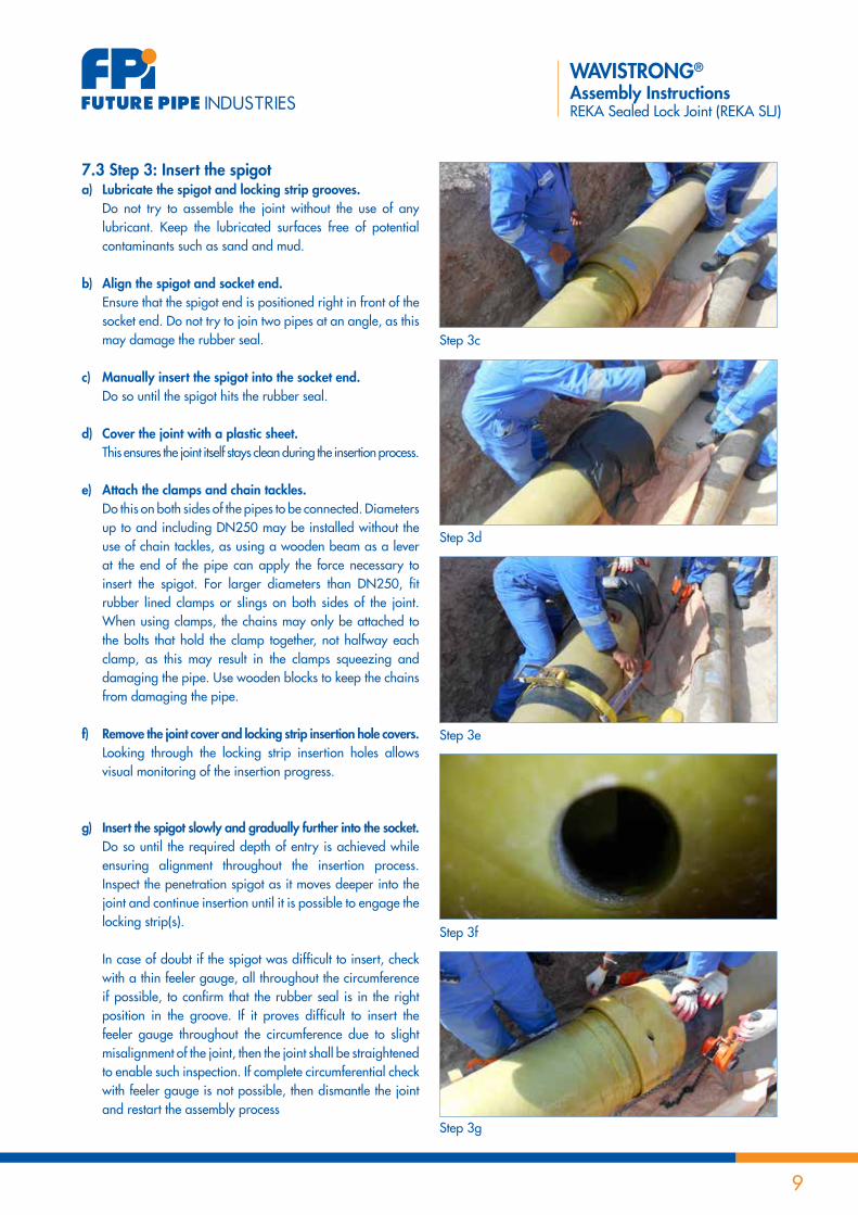
7.3 step 3: insert the spigota) lubricate the spigot and locking strip grooves. do not try to assemble the joint without the use of any
lubricant. Keep the lubricated surfaces free of potential contaminants such as sand and mud.
b) align the spigot and socket end. ensure that the spigot end is positioned right in front of the
socket end. do not try to join two pipes at an angle, as this may damage the rubber seal.
c) Manually insert the spigot into the socket end. do so until the spigot hits the rubber seal.
d) Cover the joint with a plastic sheet. this ensures the joint itself stays clean during the insertion process.
e) attach the clamps and chain tackles. do this on both sides of the pipes to be connected. diameters
up to and including dn250 may be installed without the use of chain tackles, as using a wooden beam as a lever at the end of the pipe can apply the force necessary to insert the spigot. For larger diameters than dn250, fit rubber lined clamps or slings on both sides of the joint. When using clamps, the chains may only be attached to the bolts that hold the clamp together, not halfway each clamp, as this may result in the clamps squeezing and damaging the pipe. use wooden blocks to keep the chains from damaging the pipe.
f) remove the joint cover and locking strip insertion hole covers. looking through the locking strip insertion holes allows
visual monitoring of the insertion progress.
g) insert the spigot slowly and gradually further into the socket. do so until the required depth of entry is achieved while
ensuring alignment throughout the insertion process. Inspect the penetration spigot as it moves deeper into the joint and continue insertion until it is possible to engage the locking strip(s).
In case of doubt if the spigot was difficult to insert, check with a thin feeler gauge, all throughout the circumference if possible, to confirm that the rubber seal is in the right position in the groove. If it proves difficult to insert the feeler gauge throughout the circumference due to slight misalignment of the joint, then the joint shall be straightened to enable such inspection. If complete circumferential check with feeler gauge is not possible, then dismantle the joint and restart the assembly process
step 3g
step 3f
step 3c
step 3d
step 3e

10
WAVISTRONG®
Assembly InstructionsREKA Sealed Lock Joint (REKA SLJ)
7.4 step 4: insert the locking stripa) ensure the correct locking strip is used. Verifythatthecorrectlockingstripisusedbycomparingits
dimensions with the data provided in Annex d – locking strip dimensions.
b) apply lubricant on the locking strip. make sure the tip of the locking strip is well lubricated.
c) Manually insert the locking strip in the hole. ensuring that the bevelled end rests against the inner
surface of the socket.
d) Tap the locking strip home until it completely circumferences the joint.
use a plastic or wooden mallet or a pneumatic hammer to drive the joint. the locking strip is fully inserted when its tip becomes visible through the insertion hole. by then, a part of the locking strip will still be sticking out. this is normal and allows removal of the locking strips if needed. repeat this step for the second locking strip if applicable.
e) remove all temporary supports, if any. once the locking strips are completely inserted, all
temporary supports, where installed, shall be removed to avoid the risk of losing the stretching of the joint which will be executed in the next step. replace any temporary supports with permanent bedding support.
note that at low temperatures, the locking strip may become less flexible. In this case it is advisable to heat the locking strip up to around 20°c.
step 4c
step 4d
step 4d

11
WAVISTRONG®
Assembly InstructionsREKA Sealed Lock Joint (REKA SLJ)
7.5 step 5: stretch and align the jointa) draw the first marking line. mark the insertion distance of the joint on the pipe at the
socket head.
b) pull the newly installed joint outwards. Apply axial tension on each jointed pipe to fully engage
the locking strip(s) against the stop collar. While applying this stretching force, ensure that the joint is fully straight in terms of axial alignment. stretching can be done manually for small pipe diameters. For larger diameters, mechanical pulling is required. Approximate capacity of pulling equipment is 750 kg for diameters up to and including dn500, and 1500 kg for larger diameters. If stretching is not executed correctly, the pipeline may move and subsequently fail during the field hydrotest.
c) draw the second marking line. mark the stretching distance on the pipe at the socket end.
this will reveal the amount of stretch, and will provide a baseline for further joint checks, such as joint movement.
d) apply a permitted deflection angle if necessary. this may be done at this stage only, after assembly of the
joint, for the purpose of aligning it with the support or trench layout.
refer to Annex A – Permitted angular deflections and Annex b – measuring angular deflection in the field for more information.
do not apply the maximum permitted angle blindly. Always refer to the project specific method statement or consult with the system design engineer regarding the maximum permitted deflection angles.
e) secure the joint. After correct alignment is ensured, support the joint. For underground applications, apply the correct backfill
material on both sides of the joint. Pay special attention to place the backfill material under the pipe haunches. Also, apply enough backfill to prevent trench flooding (see section 2).
For above ground applications, use the prescribed supports. this initial stage of supporting ensures that the pipe is
secured as the installation continues towards the next joint.
note that after a reasonable length of pipeline is installed, it is possible to fine-tune the pipeline’s alignment further. If this fine-tuning is done, the securing process may need to be repeated
step 5a
step 5b
step 5c
step 5c

12
WAVISTRONG®
Assembly InstructionsREKA Sealed Lock Joint (REKA SLJ)
8 sToraGe Guidelines for rubber seals, loCkinG sTrips and lubriCanT
the following guidelines shall be honoured when storing the rubber seals, the locking strips and lubricant.• Rubbersealsaredeliveredinclosedbagsorprotectiveboxesfromthefactory.Theymustbestoredintheiroriginalpackingin
a sheltered environment, inside a dry and shaded area where they are protected from direct heat sources, (sun)light, ionizing radiationandUVradiation,awayfromozonegeneratingelectricaldevicesandexhaustgases,andinacleanconditionuntiltheyarereadyforuse.WindowsofstorageroomsshouldbecoveredwithaUVblockingcoating.
• Themaximumstoragetemperatureforrubbersealsshallbe38°C.Briefperiodsofhighertemperaturesduetotemporaryclimate changes are allowed. the maximum relative humidity shall be 75%.
• Storerubbersealswithouttension(i.e.,neverhangrubberseals).• Rubbersealsshallbeusedontheso-calledFirstIn,FirstOutprinciple(FIFO),suchthatthosemostrecentlyreceivedsealis
always used last.• Lockingstripsshallbestoredinacleanconditioninashelteredenvironment,insideashadedareawheretheyareprotected
from direct sunlight until they are ready for use.• Lubricantshallbestoredinitsoriginalcontainer.Recommendedstoragetemperatureisfrom0°Cto65°C.• Duringstorage,keepallconsumablesawayfromchemicalswhichtendtoattackthem.

13
WAVISTRONG®
Assembly InstructionsREKA Sealed Lock Joint (REKA SLJ)
annex a - perMiTTed anGular defleCTions
table 1 shows the maximum allowed angular deflections for the joint.
do not apply these maximum permitted angle blindly. Always refer to the project specific method statement or consult with the system design engineer regarding the maximum permitted deflection angles.
table 1
id (mm) angular deflection
80 1°30’
100 1°30’
125 1°30’
150 1°30’
200 1°30’
250 1°30’
300 1°30’
350 1°30’
400 1°30’
450 1°30’
500 1°30’
600 1°30’
700 1°
750 1°
800 1°
900 1°
1000 1°
1200 1°

14
WAVISTRONG®
Assembly InstructionsREKA Sealed Lock Joint (REKA SLJ)
annex b - MeasurinG anGular defleCTion in THe field
Angular deflections can be measured in the field using a string line.
two ways of measuring can be performed, see Figure 1.1. measure on the outside of the joint.2. measure on the inside of the joint.
measuring always must be done in the plane of the deflection and the measured distances may never exceed the values presented in table 2. Furthermore, the surveyor must always check, record and approve the applied angular deflections prior to final securing.
table 2
pipe length(m)
angular deflection
Maximum distance d(mm)
Maximum distance d(mm)
10 1° 175 85
10 1°30’ 260 130
12 1° 200 100
12 1°30’ 300 150
Distance d
Distance D
Figure 1

15
WAVISTRONG®
Assembly InstructionsREKA Sealed Lock Joint (REKA SLJ)
annex C - rubber seal diMensions
the general shape of the rubber reKA seal is shown in Figure 2, its dimensions are grouped per diameter range and are presented in table 3.
table 3
dn(mm)
number of lips Height(mm)
Width(mm)
seal od Type a (mm)
seal od Type b (mm)
80 3 15 16 126 -
100 3 15 16 148 -
125 3 15 16 177 -
150 3 15 16 203 -
200 3 15 16 256 260
250 3 15 16 317 323
300 4 18 20 375 382
350 4 18 20 426 432
400 4 18 20 480 487
450 4 18 20 534 542
500 4 18 20 593 605
600 6 22 30 708 722
700 6 22 30 825 825
750 6 22 30 880 880
800 6 22 30 934 934
900 6 22 30 1034 -
1000 6 22 30 1142 -
1200 6 22 30 1361 -
Figure 2

16
WAVISTRONG®
Assembly InstructionsREKA Sealed Lock Joint (REKA SLJ)
annex d - loCkinG sTrip diMensions
table 4 provides the locking strip dimensions.
table 4
id (mm)pn (bar)
Quantity Height (mm) Width (mm) length (mm)Min Max
80 32 32 1 8 12 420
100 25 32 1 8 12 420
125 25 32 1 10 14 550
150 20 32 1 10 14 780
20016 20 1
10 14 78025 32 2
25012.5 20 1
16 20 133025 32 2
30012.5 20 1
16 20 133025 32 2
3508 16 1
16 20 133020 25 2
4008 16 1
16 20 170020 25 2
4508 16 1
16 20 170020 25 2
5008 12.5 1
20 24 226016 25 2
6008 12.5 1
20 24 226016 25 2
7008 12.5 1
23 40 288516 20 2
7508 12.5 1
23 40 288516 20 2
8008 12.5 1
23 40 288516 20 2
900 8 12.5 2 23 40 1765
1000 8 12.5 2 23 40 1765
1200 8 12.5 2 23 40 2260

17
WAVISTRONG®
Assembly InstructionsREKA Sealed Lock Joint (REKA SLJ)
annex e - insTallaTion TiMe
table 5 shows typical installation times per diameter, based on the following presumptions.• Uninterruptedwork.• Sufficientspaceandanopentrenchforundergroundapplications,etc.• Theuseofpoweredequipment,suchasacrane,tomovethepipe• Aninstallationcrewof3persons(twointhetrench,oneoutside).• Competentinstallationpersonnelwithoptimaltraining(seeSection4).• Moderatelysunny,dryweatherconditions.• Pipingtobeinstalledisaspartofastraightrunwithnofittings.• Excludingthehandlingtimeofpipe(example:stringingofthepipeinsideatrench).• Includingthetimetakenforclampingandassemblyofthejoint.
table 5
id (mm) Time (min.)
80 5
100 5
125 5
150 5
200 10
250 15
300 15
350 15
400 15
450 20
500 20
600 20
700 20
750 25
800 25
900 25
1000 30
1200 30

18
WAVISTRONG®
Assembly InstructionsREKA Sealed Lock Joint (REKA SLJ)
annex f - JoinT disasseMbly
If a joint requires disassembly, the following steps apply.1. Push the pipe back to free up the locking strip.2. Grip the locking strip with a pair of pliers or a plate clamp. tap the pliers or use a crane to pull the plate clamp to remove the
lockingstrip.Ifthelockingstripjams,slightlyrotateand/oralignthepipewhilepullingthestrip.3. now the joint can be released by pulling the spigot out of the socket.
this procedure does not apply to joints that contain 2 locking strips engaged with a single groove, as in the case of very large diameters such as Id ≥ 900mm.


ASSEMBLY INSTRUCTIONSREKA SEALED LOCK JOINT (REKA SLJ)
WAVISTRONG®