we n10748812 cigre africa study report master+18 final
TRANSCRIPT

CIGRE WG C1.9
CIGRE C1.9 – AFRICA STUDY REPORT
CONSEIL INTERNATIONALE DES GRANDS RESEAUX ELECTRIQUES
INTERNATIONAL COUNCIL ON LARGE ELECTRIC SYSTEMS
WORKING GROUP C1.9 OF CIGRE STUDY COMMITTEE C1 On Power System Planning and Development
Report prepared by WG C1.9 Study Committee C1
Convenor: Riaz Vajeth (Eskom South Africa)
Supported by: Kevin Leask (South Africa), Andy Bitcon (Trans-Africa Projects, South Africa), Nhlanhla
Mbuli (South Africa), Bruno Cova (CESI, Italy)
PLANNING ISSUES FOR NEWLY INDUSTRIALIZED AND
DEVELOPING COUNTRIES (AFRICA)

CIGRE WG C1.9
CIGRE C1.9 – AFRICA STUDY REPORT
ii
Contents
List of Tables ........................................................................................................................................... v
List of Figures ......................................................................................................................................... ix
Executive Summary .............................................................................................................................. xv
1. Introduction ...................................................................................................................................... 1
2. Africa's Interconnections .............................................................................................................. 10
3. Solar Power .................................................................................................................................... 27
4. Algeria ............................................................................................................................................. 29
5. Angola ............................................................................................................................................. 39
6. Benin and Togo .............................................................................................................................. 49
7. Botswana ......................................................................................................................................... 59
8. Burkina Faso .................................................................................................................................. 67
9. Burundi ........................................................................................................................................... 77
10. Cameroon ....................................................................................................................................... 83
11. Cape Verde ..................................................................................................................................... 89
12. Central African Republic .............................................................................................................. 99
13. Chad .............................................................................................................................................. 103
14. Comoros ........................................................................................................................................ 107
15. Congo ............................................................................................................................................ 111
16. Côte d’Ivoire ................................................................................................................................. 115
17. Democratic Republic of Congo ................................................................................................... 125
18. Djibouti ......................................................................................................................................... 130
19. Egypt ............................................................................................................................................. 134
20. Equatorial Guinea........................................................................................................................ 152
21. Eritrea ........................................................................................................................................... 155
22. Ethiopia ......................................................................................................................................... 160
23. Gabon ............................................................................................................................................ 168
CIGRE WG C1.9
CIGRE C1.9 – AFRICA STUDY REPORT
iii
24. Gambia .......................................................................................................................................... 172
25. Ghana ............................................................................................................................................ 183
26. Guinea ........................................................................................................................................... 198
27. Guinea-Bissau............................................................................................................................... 205
28. Kenya ............................................................................................................................................ 210
29. Lesotho .......................................................................................................................................... 219
30. Liberia ........................................................................................................................................... 225
31. Libya ............................................................................................................................................. 233
32. Madagascar .................................................................................................................................. 245
33. Malawi........................................................................................................................................... 250
34. Mali ............................................................................................................................................... 255
35. Mauritania .................................................................................................................................... 266
36. Mauritius ...................................................................................................................................... 270
37. Morocco ........................................................................................................................................ 282
38. Mozambique ................................................................................................................................. 295
39. Namibia ......................................................................................................................................... 305
40. Niger .............................................................................................................................................. 320
41. Nigeria ........................................................................................................................................... 325
42. Rwanda ......................................................................................................................................... 333
43. Sao Tome and Principe................................................................................................................ 338
44. Senegal .......................................................................................................................................... 341
45. Seychelles ...................................................................................................................................... 352
46. Sierra Leone ................................................................................................................................. 357
47. Somalia .......................................................................................................................................... 367
48. South Africa.................................................................................................................................. 372
49. Sudan............................................................................................................................................. 392
50. Swaziland ...................................................................................................................................... 407
51. Tanzania ....................................................................................................................................... 417
CIGRE WG C1.9
CIGRE C1.9 – AFRICA STUDY REPORT
iv
52. Tunisia........................................................................................................................................... 424
53. Uganda .......................................................................................................................................... 432
54. Western Sahara ............................................................................................................................ 441
55. Zambia .......................................................................................................................................... 444
56. Zimbabwe ..................................................................................................................................... 452
57. Conclusion and Recommendations ............................................................................................ 460
Appendix 1 ........................................................................................................................................... 461

CIGRE WG C1.9
CIGRE C1.9 – AFRICA STUDY REPORT
v
List of Tables
Table 1.1: List of Planning Personnel in Various African Countries ....................................................... 5
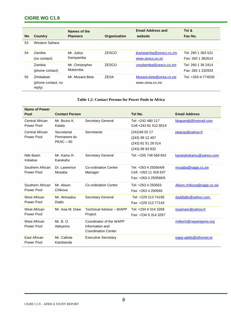
Table 1.2: Contact Persons for Power Pools in Africa ............................................................................. 8
Table 1.3: Contact Persons for Southern African Power Pool Member Countries .................................. 9
Table 2.1: Ministries responsible for energy .......................................................................................... 15
Table 2.2: Power utilities in different East Africa countries .................................................................. 15
Table 2.3: Energy regulators in East African countries .......................................................................... 15
Table 2.4: Eight key projects .................................................................................................................. 20
Table 4.1: System Statistics – Algeria .................................................................................................... 29
Table 4.2: Electricity Forecast – Algeria ................................................................................................ 32
Table 4.3: Line Forced Unavailability Rate ............................................................................................ 35
Table 4.4: Parameters of Weather Model ............................................................................................... 35
Table 5.1: Angola Annual Peak Demand, Growth at 12% p.a. [2]......................................................... 42
Table 6.1: Configuration of CEB and SBEE Transmission Network in Benin [2] ................................ 51
Table 6.2: CEB Demand Forecast [1] ..................................................................................................... 52
Table 6.3: SBEE Electricity Demand Forecast [2] ................................................................................. 53
Table 6.4: CEB Generation Statistics for 2002 [1] ................................................................................. 53
Table 6.5: CEB Generation Statistics for 2002 [1] ................................................................................. 56
Table 7.1: Short and Long Term Generation Projects ............................................................................ 62
Table 7.2: Project alternatives considered and reasons for rejection [2] ................................................ 64
Table 7.3: Base Case financial and economic returns [2] ....................................................................... 65
Table 8.1: Capacities and Duties of Electricity Sector Stakeholders in Burkina Faso [2] ..................... 68
Table 8.2: Demand Forecast for Peak Power and Energy for Burkina Faso [3] .................................... 71
Table 8.3: Evaluation of SONABEL Power Sales and Number of Customers by Category [2] ............ 72
Table 9.1: GDP Growth Rate (2002~2020) in Burundi .......................................................................... 78
Table 9.2: Assumptions Made for Load Forecast Preparation in Burundi ............................................. 78
Table 10.1: Cameroon Historic Electricity Consumption....................................................................... 84
Table 10.2: Cameroon Installed Generation Capacity ............................................................................ 85
Table 14.1: Electricity Consumption of Comores ................................................................................ 108
Table 16.1: Generation Capacity of the Côte d’Ivoire Network ........................................................... 121
Table 19.1: Statistical Data for Egypt – 2008 ....................................................................................... 136
Table 19.2: Load Forecast in Egypt ...................................................................................................... 140
Table 19.3: Customers by Sector .......................................................................................................... 142
Table 19.4: Generation Expansion Plan (2004–2012) .......................................................................... 144
Table 19.5: Supply and Demand ........................................................................................................... 144
Table 19.6: Interconnection .................................................................................................................. 145

CIGRE WG C1.9
CIGRE C1.9 – AFRICA STUDY REPORT
vi
Table 19.7: Investment Plan ................................................................................................................. 146
Table 19.8: Transmission Line Forced Unavailability Rate ................................................................. 148
Table 19.9: Parameters of Weather Model ........................................................................................... 149
Table 19.10: Operational Criteria for Definition of Operating Reserve in Egypt ................................ 150
Table 22.1: Electricity Statistics (historical & forecast) of Ethiopia .................................................... 162
Table 22.2: Installed Capacity and Generation Mix in Ethiopia – 2004 .............................................. 163
Table 22.3: Future Power Projects ........................................................................................................ 163
Table 23.1: Energy in Gabon ................................................................................................................ 168
Table 23.2: Electricity consumption 9 ................................................................................................... 169
Table 23.3: Electricity production 9 ..................................................................................................... 169
Table 24.1: The Gambian Power Demand Forecast (MW, GWh) [11] ................................................ 175
Table 24.2: The Gambian Power Demand Forecast (MW, GWh) ....................................................... 176
Table 25.1: Ghana Power Demand Forecast......................................................................................... 187
Table 25.2: Financial Performance of VRA, 1997–2002 (in ¢Billion) ................................................ 194
Table 25.3: Financial Performance of ECG, 1997–2002 (in ¢Billion) ................................................. 194
Table 25.4: Distribution of Staff by Category ...................................................................................... 196
Table 26.1: Guinea Peak Demand Forecast [1] .................................................................................... 200
Table 26.2: Future and Existing Installed Capacity of the Guinea Electric Power System [1] ............ 201
Table 27.1: Electricity Demand Forecast for Guinea-Bissau [1] .......................................................... 206
Table 29.1: LEC General Information April 2004 to March 2005 ....................................................... 220
Table 30.1: Sites with Hydro-electric Generation Potential [8] ........................................................... 227
Table 30.2: Total Electricity Consumed [2] ......................................................................................... 227
Table 30.3: Liberia Electricity Demand Forecast [10] ......................................................................... 228
Table 31.1: System Statistics – Libya ................................................................................................... 233
Table 31.2: Statistical Data – Libya – 2008 .......................................................................................... 234
Table 31.3: Demand and Generation Forecast in Libya ....................................................................... 237
Table 31.4: Transmission Line Forced Unavailability Rate ................................................................. 241
Table 31.5: Parameters of Weather Model ........................................................................................... 241
Table 31.6: Operational Criteria for Definition of Operating Reserve in Libya .................................. 242
Table 33.1: ESCOM Utility Data – Malawi ......................................................................................... 251
Table 33.2: Maximum Demand Forecast in Malawi ............................................................................ 252
Table 33.3: Sales Forecast in Malawi ................................................................................................... 252
Table 33.4: Future Generation Projects in Malawi ............................................................................... 253
Table 34.1: Government Energy Organizations – Mali ........................................................................ 256
Table 34.2: Electricity Demand Forecast .............................................................................................. 258
Table 34.3: Existing and Proposed Power Stations .............................................................................. 258
Table 34.4: Total Electricity Production ............................................................................................... 259

CIGRE WG C1.9
CIGRE C1.9 – AFRICA STUDY REPORT
vii
Table 34.5: Installed Production Capacity ............................................................................................ 259
Table 34.6: Efficiency of the Interconnected Network ......................................................................... 262
Table 36.1: Probable Sales Forecast by Customer Segment................................................................. 272
Table 36.2: The Probable Generation Expansion Plan ......................................................................... 278
Table 37.1: Statistical Data for Morocco – 2008 .................................................................................. 283
Table 37.2: Demand and Generation Forecast in Morocco .................................................................. 286
Table 37.3: Morocco Generation Projects ............................................................................................ 288
Table 37.4: Transmission Line Forced Unavailability Rate ................................................................. 291
Table 37.5: Parameters of Weather Model ........................................................................................... 292
Table 39.1: Voltage Conditions ............................................................................................................ 314
Table 39.2: The Namibian Grid Short Circuit Profile .......................................................................... 316
Table 40.1: Capacity of Interconnecting Lines – Niger ........................................................................ 321
Table 40.2: Electricity Consumption – Niger ....................................................................................... 322
Table 41.1: Nigeria Installed Generation Capacity............................................................................... 329
Table 42.1: High, Low and Base Scenario of the GDP ........................................................................ 334
Table 42.2: The Elements and Assumptions Affecting the Load Forecast in Rwanda ........................ 334
Table 42.3: Major Future Projects in Rwanda ...................................................................................... 336
Table 44.1: Senegal Electricity Demand Forecast [15] ........................................................................ 345
Table 44.2: Distribution of Installed Capacity of SENELEC Power System [15] ............................... 345
Table 44.3: Generation Installation and Installed Capacity (MW) of SENELEC in 2005 [15] ........... 346
Table 46.1: Generation Capacity of Kingtom Power Station (November 2006) .................................. 359
Table 46.2: Forecasted Installed Capacity for 2015 ............................................................................. 361
Table 46.3: Total Electricity Production ............................................................................................... 361
Table 46.4: Installed Production Capacity ............................................................................................ 361
Table 48.1: Sales of electricity and number of customers in South Africa .......................................... 378
Table 48.2: Voltage Limits for Planning Purposes ............................................................................... 381
Table 48.3: Standard Voltage Levels as used in South Africa ............................................................. 381
Table 48.4: Target Voltage for Planning Purposes ............................................................................... 382
Table 48.5: Transmission and Distribution equipment in service in 2010 ........................................... 385
Table 48.6: New Transmission equipment to be added during the period from 2010 and 2019 as per the
Transmission Development Plan .......................................................................................................... 385
Table 48.7: Eskom Power Station Capacities in 2010 .......................................................................... 387
Table 48.8: New power stations under construction ............................................................................. 388
Table 49.1: Historical Growth Rate (GDP) .......................................................................................... 395
Table 49.2: Electricity Consumption [4] .............................................................................................. 395
Table 49.3: Peak Demand Forecast (MW) & Growth Rate (%) ........................................................... 397
Table 49.4: Electricity Consumption Forecast (GWh) ......................................................................... 397

CIGRE WG C1.9
CIGRE C1.9 – AFRICA STUDY REPORT
viii
Table 49.5: Installed Generation Capacity – MW ................................................................................ 399
Table 50.1: Swaziland’s Energy Demand Projections by Fuel Type (Million Gigajoules) [11] .......... 410
Table 51.1: Tanzania Load Forecast Model ......................................................................................... 418
Table 51.2: Tanzania Forecast Summary.............................................................................................. 419
Table 51.3: Current and Future Generation and Transmission Projects. .............................................. 421
Table 52.1: Demand and Generation Forecast in Tunisia..................................................................... 424
Table 52.2: Transmission Line Forced Unavailability Rate ................................................................. 428
Table 52.3: Parameters of Weather Model ........................................................................................... 428
Table 53.1: Basis Assumptions for the Uganda Load Forecast ............................................................ 436
Table 53.2: Uganda Forecast Summary ................................................................................................ 436
Table 53.3: Electricity Supply by Source ............................................................................................. 438
Table 55.1: Summary of Generation Projects ....................................................................................... 448
Table 56.1: Zimbabwe’s Planned Generation Projects ......................................................................... 455
Table 56.2: Zimbabwe Power Imports.................................................................................................. 457
Table 56.3: Zimbabwe Power imports[1] ............................................................................................. 458
Table 56.4: Internal supply of electricity within Zimbabwe[1] ............................................................ 458
CIGRE WG C1.9
CIGRE C1.9 – AFRICA STUDY REPORT
ix
List of Figures
Figure 2.1: Map of Africa and the future interconnection potential ....................................................... 10
Figure 2.2: Interconnections and generators in Southern Africa [3] ...................................................... 12
Figure 2.3: Poor interconnection in Africa [1] ........................................................................................ 13
Figure 2.4: Future interconnection in the Western region in Africa [1] ................................................. 14
Figure 2.5: East African Power Pool ...................................................................................................... 16
Figure 2.6: Powerlines connecting Kenya to her neighbouring states .................................................... 18
Figure 2.7: Map of central Africa [1] ...................................................................................................... 19
Figure 2.8: Northern Africa Power Pool ................................................................................................. 21
Figure 3.1: Schematic Diagram of CSP process ..................................................................................... 27
Figure 3.2: PV array ................................................................................................................................ 28
Figure 5.1: Map of Angola [1] ................................................................................................................ 39
Figure 5.2: Electricity Supply Industry in Angola .................................................................................. 40
Figure 5.3: Energy Mix ........................................................................................................................... 44
Figure 5.4: More than 7000 MW hydro potential along Kwanza River ................................................. 47
Figure 6.1: Geographic Map of Benin & Togo ....................................................................................... 49
Figure 6.2: CEB’s Generation, Transmission and SBEE Distribution Resouces [1] ............................. 52
Figure 7.1: Electricity Supply Industry Structure in Botswana .............................................................. 59
Figure 7.2: Market Sector Botswana ...................................................................................................... 60
Figure 7.3: Annual Energy Sent Out in Botswana .................................................................................. 61
Figure 7.4: Botswana Power Network .................................................................................................... 63
Figure 8.1: Geographic Map of Burkina Faso ........................................................................................ 67
Figure 8.2: Burkina Faso Transmission Network ................................................................................... 70
Figure 9.1: Peak Power Demand in Burundi .......................................................................................... 79
Figure 9.2: Energy Demand in Burundi .................................................................................................. 79
Figure 10.1: Electricity production 2000-2011 [1] ................................................................................. 84
Figure 10.2: Electricity consumption 2000-2011 [2] .............................................................................. 84
Figure 11.1: Energy usage sectors (Source: GESTO 2011 and ELECTRA data) ................................. 89
Figure 11.2: Electricity production 2000-2011 ....................................................................................... 90
Figure 11.3: Electricity production 2000-2011 ....................................................................................... 91
Figure 11.4: Cape Verde map ................................................................................................................. 92
Figure 11.5: Cabeolica wind farm project .............................................................................................. 93
Figure 11.6: Solar potential in Cape Verde ............................................................................................ 94
Figure 11.7: Wind potential in Cape Verde ............................................................................................ 95
Figure 11.8: Hydropower potential in Cape Verde ................................................................................. 96

CIGRE WG C1.9
CIGRE C1.9 – AFRICA STUDY REPORT
x
Figure 12.1: Map of CAR and neighbouring countries .......................................................................... 99
Figure 13.1: Map of Chad and surrounding countries .......................................................................... 103
Figure 13.2: Chad electricity production from 2000-2011 ................................................................... 104
Figure 13.3: Chad electricityconsumption from 2000-2011 ................................................................. 104
Figure 15.1: Electricity production 2000-2011 [1] ............................................................................... 112
Figure 15.2: Electricity consumption 2000-2011 [2] ............................................................................ 112
Figure 16.1: Geographical Location of Côte d'Ivoire ........................................................................... 115
Figure 16.2: Côte d’Ivoire Electricity Structure ................................................................................... 117
Figure 16.3: Côte d’Ivoire Electricity Map ........................................................................................... 118
Figure 16.4: Côte d’Ivoire’s Growth in Electricity Demand and GDP ................................................ 119
Figure 16.5: Côte d’Ivoire Forecasted Annual Maximum Demand and Consumption ........................ 120
Figure 17.1: Load Forecast for West Network SNEL .......................................................................... 126
Figure 17.2: Load Forecast for South Network SNEL ......................................................................... 126
Figure 17.3: Inga1 - 351 MW ............................................................................................................... 127
Figure 17.4: Inga2: 1424 MW .............................................................................................................. 128
Figure 17.5: Inga3 - 3500 MW ............................................................................................................. 128
Figure 17.6: Location of Grand Inga .................................................................................................... 129
Figure 19.1: Current Electricity Market in Egypt. ................................................................................ 135
Figure 19.2: Targeted Electricity Market in Egypt. .............................................................................. 136
Figure 19.3: Daily Load Curve (Maximum Discharge) in Egypt ......................................................... 139
Figure 19.4: Daily Load Curve (Minimum Discharge) in Egypt.......................................................... 139
Figure 19.5: Peak Load Curve 2003/2004 to 2004/2005 in Egypt ....................................................... 140
Figure 19.6: Energy Demand Curve in Egypt ...................................................................................... 141
Figure 19.7: Generation Mix in Egypt .................................................................................................. 141
Figure 19.8: Energy Forecast for Egypt ................................................................................................ 142
Figure 19.9: Import and Export ............................................................................................................ 145
Figure 21.1: Electricity Consumption by Sector................................................................................... 157
Figure 22.1: National Grid of Ethiopia [1] ........................................................................................... 161
Figure 24.1: The OMVG Network [1] .................................................................................................. 173
Figure 24.2: Electricity Net Generation [10] ....................................................................................... 176
Figure 24.3: Electricity Nett Consumption [10] ................................................................................... 177
Figure 24.4: Electricity Installed Capacity [10] .................................................................................... 178
Figure 25.1: National Grid of Ghana [1] .............................................................................................. 183
Figure 25.2: Ghana Electricity Status in 2006 ...................................................................................... 186
Figure 25.3: Generation Sources........................................................................................................... 188
Figure 25.4: Electricity Nett Generation ............................................................................................... 189
Figure 25.5: Ghana Installed Capacity.................................................................................................. 190

CIGRE WG C1.9
CIGRE C1.9 – AFRICA STUDY REPORT
xi
Figure 25.6: Nett Electricity Consumption ........................................................................................... 191
Figure 25.7: Communities Connected by NES ..................................................................................... 193
Figure 26.1: Guinea Transmission Network [3] ................................................................................... 199
Figure 27.1: Map of Guinea Bissau [4] ................................................................................................ 206
Figure 28.1: Electricity Supply by Source in Kenya. ........................................................................... 210
Figure 28.2: Electricity Supply Industry Structure in Kenya ............................................................... 211
Figure 28.3: GDP and Sales Annual Growth in Kenya ........................................................................ 212
Figure 28.4: Sensitivity Analysis of Load Forecasting in Kenya ......................................................... 213
Figure 28.5: Daily Electricity Demand Pattern in Kenya ..................................................................... 213
Figure 28.6: Kenya Electrical Power Network ..................................................................................... 215
Figure 28.7: Kenya Electrical Power Generation ................................................................................. 216
Figure 28.8: Regional Interconnection ................................................................................................. 217
Figure 29.1: Electricity Supply Industry Structure in Lesotho ............................................................. 219
Figure 29.2: Annual Maximum Demand in Lesotho ............................................................................ 221
Figure 29.3: Annual Energy Sent Out in Lesotho................................................................................. 221
Figure 29.4: Electricity Supplied by Source in Lesotho ....................................................................... 222
Figure 30.1: Map of the Republic of Liberia ........................................................................................ 226
Figure 30.2: Total Electricity Consumed Expressed in Kilowatt-hours [2] ......................................... 228
Figure 30.3: Growth in LEC Customers and Collections [6] ............................................................... 231
Figure 31.1: System Statistics – Libya ................................................................................................. 234
Figure 31.2: Recent accomplishments .................................................................................................. 243
Figure 32.1: Electricity production for 2000-2011 ............................................................................... 246
Figure 32.2: Electricity consumption for 2000-2011 ............................................................................ 247
Figure 32.3: Madagascar Renewable Capacity over a 5 year period. ................................................... 247
Figure 32.4: Renewables as % Total Capacity ..................................................................................... 248
Figure 33.1: Electricity Supply Industry Structure in Malawi .............................................................. 250
Figure 34.1: National Grid of Mali ....................................................................................................... 255
Figure 34.2: Electricity Consumption in TWh ..................................................................................... 259
Figure 34.3: Gross Generation of EDM-SA ......................................................................................... 260
Figure 34.4: Distribution of EDM-SA Production by Source and Operation Centre ........................... 260
Figure 34.5: Distribution of Gross Generation by Type of Station ...................................................... 261
Figure 35.1: Electricity production between 2000-2011 ...................................................................... 267
Figure 35.2: Electricity consumption between 2000-2011 ................................................................... 267
Figure 36.1: Electricity Supply Industry Structure in Mauritius .......................................................... 271
Figure 36.2: Electricity Sales vs. GDP in Mauritius ............................................................................. 271
Figure 36.3: Probable Forecast of Electricity Sales by Customer Segment in Mauritius..................... 273
Figure 36.4: Peak Demand Forecast MW in Mauritius ........................................................................ 273

CIGRE WG C1.9
CIGRE C1.9 – AFRICA STUDY REPORT
xii
Figure 36.5: Energy Forecast GWh in Mauritius.................................................................................. 274
Figure 36.6: Generation Mix in Mauritius ............................................................................................ 275
Figure 36.7: The Generation and Transmission Network of Mauritius ................................................ 276
Figure 36.8: Energy Balance with Existing and Committed Resources ............................................... 277
Figure 36.9: Effective Capacity Balance with Existing and Committed Resources ............................. 278
Figure 36.10: 10-Year Outlook for New Generation Resources .......................................................... 279
Figure 37.1: Electricity Supply Industry Structure in Morocco ........................................................... 282
Figure 37.2: Future Electricity Market in Morocco .............................................................................. 283
Figure 37.3: Electricity Sales GWh in Morocco ................................................................................... 285
Figure 37.4: Number of Customers in Morocco ................................................................................... 286
Figure 37.5: Energy by Category in Morocco ...................................................................................... 286
Figure 37.6: Installed Capacity Mix in Morocco .................................................................................. 287
Figure 38.1: Electricity Supply Industry Structure in Mozambique .................................................... 296
Figure 38.2: Medium Growth Demand Scenario in Mozambique ....................................................... 298
Figure 38.3: Demand and Energy Supplied in Mozambique ................................................................ 299
Figure 38.4: National Grid Status in Mozambique ............................................................................... 299
Figure 38.5: Development of National Grid in Mozambique ............................................................... 300
Figure 38.6: 100-MW gas-fuelled power generation plant ................................................................... 302
Figure 39.1: Geographic Location of the REDs ................................................................................... 306
Figure 39.2: Overview of the Namibian Grid with the Caprivi Link Interconnector ........................... 308
Figure 39.3: Predicted Load Growth [5] ............................................................................................... 311
Figure 39.4: Forecast Demand Increase in MW for Next 25 Years [6] ................................................ 312
Figure 41.1: Nigeria Electricity Network ............................................................................................. 327
Figure 41.2: Nigeria Forecasted Consumption and Annual Maximum Demand ................................. 328
Figure 42.1: Peak Power Forecast in Rwanda. ..................................................................................... 335
Figure 42.2: Energy Demand Forecast in Rwanda. .............................................................................. 335
Figure 43.1: Electricity production for 2000-2011 ............................................................................... 338
Figure 43.2: Electricity consumption for 2000-2011 ............................................................................ 338
Figure 44.1: Transmission and Distribution Network of Senegal [15] ................................................. 341
Figure 44.2: Senegal Existing and Planned Transmission Network [1] ............................................... 344
Figure 44.3: Existing and Planned Thermal Generation [1] ................................................................. 346
Figure 45.1: Peak Demand (MW) 20002 - 2008 .................................................................................. 354
Figure 45.2: Consumption per Category of Customers 2008 ............................................................... 355
Figure 46.1: Geographic Map of Sierra Leone [1] ............................................................................... 357
Figure 46.2: Interconnected Countries .................................................................................................. 363
Figure 47.1: A map of Somalia ............................................................................................................. 367
Figure 47.2: Electricity production for 2000-2011 ............................................................................... 370

CIGRE WG C1.9
CIGRE C1.9 – AFRICA STUDY REPORT
xiii
Figure 47.3: Electricity consumption for 2000-2011 ............................................................................ 370
Figure 48.1: Electricity Supply Industry Structure in South Africa ..................................................... 373
Figure 48.2: Existing Electricity Supply Structure in South Africa ..................................................... 374
Figure 48.3: The Eskom Holdings Limited structure in 2010 .............................................................. 376
Figure 48.4: Historical and Project Demand Forecast for South Africa from 1951 to 2051 ................ 377
Figure 48.5: Typical Weekly Load Profile in South Africa. ................................................................. 379
Figure 48.6: System Frequency Limits for South Africa ...................................................................... 382
Figure 48.7: South Africa Electricity Planning Process Flow Chart .................................................... 384
Figure 48.8: Map of the major Transmission Network of South Africa as in 2009 ............................. 384
Figure 48.9: Map of the Transmission Development Plan for the period 2010 to 2019 showing the
major transmission projects .................................................................................................................. 386
Figure 48.10: Map of the existing Eskom power stations in 2009 ....................................................... 387
Figure 48.11: Crossrope Suspension for TX lines ................................................................................ 390
Figure 48.12: Guyed-V Suspension for TX lines ................................................................................. 391
Figure 49.1: National Grid of Sudan [3, 6] ........................................................................................... 394
Figure 49.2: Peak Demand Forecast for Sudan to 2030 ....................................................................... 397
Figure 49.3: Sudan Electricity Generation by Source [2]. .................................................................... 398
Figure 49.4: Generation Forecast and Generation Mix Based on Forecast to 2030 ............................. 401
Figure 49.5: Planned Sudan Transmission Network for year 2030 ...................................................... 404
Figure 50.1: Electricity Supply Industry Structure in Swaziland ......................................................... 408
Figure 50.2: Proposed SEB Transmission System [2] .......................................................................... 409
Figure 50.3: Electricity Net Generation [9] .......................................................................................... 411
Figure 50.4: Electricity Net Consumption [9] ...................................................................................... 411
Figure 50.5: Electricity Installed Capacity [9] ...................................................................................... 412
Figure 51.1: Electricity Supply Industry Structure in Tanzania ........................................................... 418
Figure 51.2: Demand Forecast in Tanzania .......................................................................................... 419
Figure 51.3: Energy Forecast in Tanzania ............................................................................................ 420
Figure 53.1: Electricity Sector Structure in Uganda ............................................................................. 433
Figure 53.2: Bujagali Falls project........................................................................................................ 434
Figure 53.3: Bugaji falls project ........................................................................................................... 435
Figure 53.4: Demand Forecast in Uganda ............................................................................................ 437
Figure 53.5: Energy Forecast in Uganda .............................................................................................. 437
Figure 54.1: Electricity consumption between 2000 and 2011 ............................................................. 442
Figure 54.2: Electricity production between 2000 and 2011 ................................................................ 442
Figure 55.1: Structure of Main Power Players in Zambia .................................................................... 445
Figure 55.2: The Projected Electricity Demand Forecast in Zambia .................................................... 446
Figure 55.3: Energy Forecast in Zambia............................................................................................... 446

CIGRE WG C1.9
CIGRE C1.9 – AFRICA STUDY REPORT
xiv
Figure 55.4: Electricity Supply by Source ............................................................................................ 447
Figure 55.5: Zambia’s Power Network ................................................................................................. 448
Figure 55.6: ZESCO Top Management Structure ................................................................................ 450
Figure 56.1: Structure of the Electricity Supply Industry of Zimbabwe .............................................. 452
Figure 56.2: Electricity Regulatory Structure of Zimbabwe ................................................................ 453
Figure 56.3: Energy Demand by Sector in Zimbabwe ......................................................................... 454
Figure 56.4: Demand and Energy Forecast for Zimbabwe ................................................................... 454
Figure 56.5: Planned Short Term Generation Projects – Zimbabwe .................................................... 456
Figure 56.6: Zimbabwe Grid with Proposed Projects ........................................................................... 457
CIGRE WG C1.9
CIGRE C1.9 – AFRICA STUDY REPORT
xv
Executive Summary
This report by Working Group C1.9 is submitted to Study Committee C1 to meet the terms of
reference established in December 2004. The two main objectives of the Working Group are:
1. To provide a platform for the discussion and exchange of information and experience on
power system planning among newly industrialized and developing countries – Africa;
2. To publish a document that summarizes planning practices and issues for each participating
utility, that would be useful for benchmarking and comparison.
In order to meet the first objective, several organization meetings were held and much e-mail
correspondence took place, and an email contact group was created and is attached here as
Appendix 1. In addition, a presentation was done at the Southern African Power Pool meeting, which
was held on 14 and 15 March 2007 in Livingstone, Zambia. A presention of C1.9 work was made at
the 16th
Congress of UPDEA in Nairobi, from 24–26 June 2008.
A workshop was also held in Cape Town, South Africa in 2009. A lot of information was also gathered
using email distribution lists, one-on-one phone calls and from various internet sources. Some of the
information was used directly from the internet source and the website address is referenced in general,
although in some cases multiple references from a single source may have been grouped. In addition
three workgroup meetings were held in 2008, three in 2009, and two in 2010 and one in 2011.
To meet the second objective, this report entitled ‘Planning Issues for Newly Industrialized and
Developing Countries’ is presented to Study Committee C1. This document is divided into chapters.
Chapter 1 provides the background to the Working Group.
Chapters 2 to 55 set out as much information as has been made available and has been collated from
various sources, in respect of each of the 54 African countries.
Each chapter in respect of an African country is sub-divided into seven sections, as follows:
Section 1: Electricity Industry Structure
Section 2: Load and Energy Forecasting
Section 3: Planning and Design Criteria
Section 4: Planning Approaches and Methods
Section 5: Specific Technical Issues
Section 6: Financing Issues
Section 7: Human Resources

CIGRE WG C1.9
CIGRE C1.9 – AFRICA STUDY REPORT
xvi
1. General Information
The statistics listed below are from various sources including www.africapedia.com,
http://datamarket.com, and www.estandardsforum.org, some of which are conflicting. In addition,
some are estimated figures where no actual figures are available. This data must therefore be read in
this context and has been included for broad information purposes only.
The following overall perspectives are important to note:
o Only 24% of sub-Saharan Africa’s population has access to electricity.
o In 2008, the population without access to electricity was 590 million.
o Electrification will have a positive impact on agriculture, industry development and
poverty reduction.
No Country Year MW
GWh
Consumption
Population
(Million) KWh/person
% of Population with
Access to Electricity
1 Algeria 2006 6468 31000 33.3 931 98
2 Angola 2005 668 2201 16.9 130 15
3 Benin 2008 128 587 8.7 71 24
4 Botswana 2005 503 2602 1.8 1446 39
5 Burkina Faso 2005 124 480 13.3 36 7
6 Burundi 2005 54 161 7 23 2
7 Cameroon 2005 855 3435 16.4 209 47
8 Cape Verde 2005 7 42 0.4 105 67
9 Central African
Republic
2005 40 101 3.8 27 8
10 Chad 2005 86 88 9.8 9 2
11 Comoros 2005 5 19 0.67 28 46
12 Congo 2005 121 572 4 143 20
13 Côte d’Ivoire 2008 815 2900 20.8 139 26
14 Democratic
Republic of
Congo
2005 2442 1028 60 88 6
15 Djibouti 2006 85 227 0.56 405 70
16 Egypt 2005 18544 84490 79 1069 98
17 Equatorial
Guinea
2005 18 26 0.54 48 *
18 Eritrea 2005 60 228 4.5 51 20
19 Ethiopia 2005 745 2577 75 34 15
20 Gabon 2005 411 1241 1.4 886 48
21 Gambia 2005 220 204 1.6 84 25

CIGRE WG C1.9
CIGRE C1.9 – AFRICA STUDY REPORT
xvii
No Country Year MW
GWh
Consumption
Population
(Million) KWh/person
% of Population with
Access to Electricity
22 Ghana 2007 1540 6906 22 358 47
23 Guinea 2006 191 833 9.5 88 19
24 Guinea-Bissau 2005 8 56 1.6 40 12
25 Kenya 2005 1066.4 4464 34 131 15
26 Lesotho 2005 108 339 2 170 11
27 Liberia 2007 335 331 3.5 84.8 10
28 Libya 2005 4900 18180 5.7 3189 97
29 Madagascar 2005 1050 973 18 54 15
30 Malawi 2005 260 1299 12.5 104 7
31 Mali 2006 297 804 12.3 65 15
32 Mauritania 2005 105 231 3.1 75 28
33 Mauritius 2006 367 2068 1.3 1590 94
34 Morocco 2005 4621 20670 31 667 85
35 Mozambique 2005 383 9127 21.4 426 7
36 Namibia 2005 491 2976 2.1 1488 34
37 Niger 2005 58 438 11.7 37 10
38 Nigeria 2005 5900 16880 130.5 129 46
39 Rwanda 2005 35 198 8.4 24 6
40 Sao Tome and
Principe
2005 10 38 0.2 85 50
41 Senegal 2006 405 2395 11.7 205 33
42 Seychelles 2006 93 217 0.09 2411 99
43 Sierra Leone 2005 105 228 6.03 38 <10
44 Somalia 2005 70 251 12 21 8
45 South Africa 2007 36208 241400 46.6 5180 80
46 Sudan 2005 760 3298 41 80 30
47 Swaziland 2007 200 1200 1.2 1000 27
48 Tanzania 2005 654 1199 38.4 31 11
49 Togo 2005 90 576 6 96 17
50 Tunisia 2005 2016 11170 11 1015 99
51 Uganda 2005 330 1674 27 62 9
52 Western
Sahara
2005 58 79 0.3 263
53 Zambia 2005 1755 8655 11.7 740 22
54 Zimbabwe 2005 1397 12270 13.2 930 34

CIGRE WG C1.9
CIGRE C1.9 – AFRICA STUDY REPORT
xviii
Summary of Load Forecasting Methods Employed in African Utilities
The table below summarizes the load forecasting methods employed. Many countries did not respond
to the request for information below, and it is envisaged that the countries can send replies to the
convenor, so that it can be considered for a possible future edition of this report. The same applies to
the other tables that follow this one.
No Country
Historical
Trend
Known
Loads*
Electrifica
tion
Target
Regression
Analysis
Sectoral
Analysis
End-Use
Method
Top-Down
Approach
Bottom-up
Approach
1 Algeria
2 Angola
3 Benin
4 Botswana Y Y Y Y
5 Burkina Faso Y
6 Burundi Y Y Y Y
7 Cameroon
8 Cape Verde
9 Central African
Republic
10 Chad
11 Comoros
12 Congo
13 Côte d’Ivoire Y Y Y
14 Democratic
Republic of
Congo
15 Djibouti
16 Egypt Y Y Y
17 Equatorial
Guinea
18 Eritrea Y
19 Ethiopia Y Y Y
20 Gabon Y Y Y Y
21 Gambia
22 Ghana
23 Guinea
24 Guinea-Bissau
25 Kenya Y Y Y Y
26 Lesotho
27 Liberia
28 Libya Y

CIGRE WG C1.9
CIGRE C1.9 – AFRICA STUDY REPORT
xix
No Country
Historical
Trend
Known
Loads*
Electrifica
tion
Target
Regression
Analysis
Sectoral
Analysis
End-Use
Method
Top-Down
Approach
Bottom-up
Approach
29 Madagascar
30 Malawi Y Y Y
31 Mali
32 Mauritania
33 Mauritius Y Y
34 Morocco
35 Mozambique Y Y Y Y Y
36 Namibia Y Y Y
37 Niger
38 Nigeria
39 Rwanda Y Y Y Y Y
40 Sao Tome and
Principe
41 Senegal Y Y Y Y
42 Seychelles
43 Sierra Leone
44 Somalia
45 South Africa Y Y Y Y Y Y
46 Sudan Y Y
47 Swaziland Y Y Y
48 Tanzania Y Y Y Y
49 Togo
50 Tunisia
51 Uganda Y Y Y Y
52 Western
Sahara
53 Zambia Y Y Y Y Y
54 Zimbabwe Y Y Y Y Y
* Rural target/captive loads
Planning and Design Criteria
The table below summarizes generation planning criteria applied to the African electricity utilities. In
terms of planned reserve margin, most of the African countries maintain a figure of not less than 10%.

CIGRE WG C1.9
CIGRE C1.9 – AFRICA STUDY REPORT
xx
Summary of Generation Planning Criteria in African Countries
No Country Loss of Units
LOLP
Hours/year
Planned
Reserve Margin
% Fuel Mix Policy RE Policy
1 Algeria
2 Angola > 15%
3 Benin
4 Botswana > 15%
5 Burkina Faso
6 Burundi > 15%
7 Cameroon
8 Cape Verde
9 Central African
Republic
10 Chad
11 Comoros
12 Congo
13 Côte d’Ivoire > 15%
14 Democratic
Republic of Congo
±10% Y
15 Djibouti
16 Egypt > 10%
17 Equatorial Guinea
18 Eritrea
19 Ethiopia
20 Gabon
21 Gambia
22 Ghana
23 Guinea
24 Guinea-Bissau
25 Kenya 240 >10%
26 Lesotho > 10%
27 Liberia
28 Libya 5-24 +/-15%
29 Madagascar
30 Malawi
31 Mali
32 Mauritania
33 Mauritius 20%–25%
34 Morocco > 15%
35 Mozambique > 15%

CIGRE WG C1.9
CIGRE C1.9 – AFRICA STUDY REPORT
xxi
No Country Loss of Units
LOLP
Hours/year
Planned
Reserve Margin
% Fuel Mix Policy RE Policy
36 Namibia
37 Niger
38 Nigeria
39 Rwanda > 15%
40 Sao Tome and
Principe
41 Senegal
42 Seychelles
43 Sierra Leone
44 Somalia
45 South Africa 24 > 15%
46 Sudan
47 Swaziland
48 Tanzania > 15%
49 Togo
50 Tunisia
51 Uganda > 15%
52 Western Sahara
53 Zambia > 15%
54 Zimbabwe > 15%
The table below summarizes the main parameters of the transmission planning criteria applied by
African countries. Most of the countries use deterministic criteria.

CIGRE WG C1.9
CIGRE C1.9 – AFRICA STUDY REPORT
xxii
Summary of Transmission Planning Criteria in African Countries
No Country N-1 N-2
Voltage
Stability
Reliability
Evaluation
Voltage*
Frequency
Normal
1 Algeria y +/-5% +/-0.2%
2 Angola ±5%
3 Benin y
214 Botswana ±5%
5 Burkina Faso
6 Burundi
7 Cameroon
8 Cape Verde
9 Central African
Republic
±5%
10 Chad
11 Comoros
12 Congo
13 Côte d’Ivoire y
14 Democratic Republic
of Congo
15 Djibouti
16 Egypt ±5% ±2%
17 Equatorial Guinea
18 Eritrea
19 Ethiopia
20 Gabon y +/-5%
21 Gambia
22 Ghana
23 Guinea
24 Guinea-Bissau
25 Kenya ±5% ±2%
26 Lesotho
27 Liberia
28 Libya y
29 Madagascar
30 Malawi
31 Mali
32 Mauritania
33 Mauritius y ±5% ±0.2 Hz
34 Morocco

CIGRE WG C1.9
CIGRE C1.9 – AFRICA STUDY REPORT
xxiii
No Country N-1 N-2
Voltage
Stability
Reliability
Evaluation
Voltage*
Frequency
Normal
35 Mozambique
36 Namibia
37 Niger
38 Nigeria
39 Rwanda
40 Sao Tome and
Principe
41 Senegal
42 Seychelles
43 Sierra Leone
44 Somalia
45 South Africa ±5% 1.5%Hz
46 Sudan
47 Swaziland
48 Tanzania
49 Togo
50 Tunisia
51 Uganda
52 Western Sahara
53 Zambia ±5%
54 Zimbabwe ±5%
*Normal & contingency
Planning Approaches and Methods
The planning approach and methods employed by each country depends on the criteria adopted.
Mauritius exercises N-2 criteria, and provides sufficient generation capacity to meet double
contingency.
South Africa and Egypt adopts both N-1 and N-2 criteria where necessary.
Methods for transmission planning seem to be uniform throughout African countries. Following the
establishment of the load forecast and generation expansion, transmission planning is carried out.
South Africa has presented flow chart diagrams of their planning steps.
Specific Technical Issues
Only a few countries responded to items under specific technical issues. We believe that other
countries/utilities have or are addressing the listed issues.

CIGRE WG C1.9
CIGRE C1.9 – AFRICA STUDY REPORT
xxiv
Financing Issues
The project finance of most African power utilities depends on company generated revenues,
government support, the World Bank, donors, lending agencies and the International Development
Association (IDA).
Human Resources
With regard to generation and transmission planning, many African utilities employ external
consultants. There is generally a shortage of skills in this sector.
CIGRE WG C1.9
CIGRE C1.9 – AFRICA STUDY REPORT
1
1. Introduction
1.1 Contents of this Report
1.1.1 This report comprises of chapters to cover the introduction and the information collected in
respect of each of the 54 African countries, as follows:
(a) Chapter 1: Introduction; provides background to the Working Group, terms of reference
and list of contributors.
(b) Chapters 2 to 55: As much information as has been made available and has been
collected from various sources, is set out in respect of each of the 54 African countries.
1.1.2 The chapters in respect of each country comprise of seven sections, as detailed below:
(a) Section 1: Electricity Industry Structure; outlines current and future industry structures
in the participating countries, including issues and problems with respect to
electrification.
(b) Section 2: Load/Energy Forecasting; discusses methods for forecasting including
factors, organization and coordination.
(c) Section 3: Planning and Design Criteria; outlines both generation and transmission
planning criteria used by each country/utility.
(d) Section4: Planning Approaches and Methods; discusses how planning is carried out in
each country/utility.
(e) Section5: Specific Technical Issues; outlines selected technical issues and how they are
resolved.
(f) Section 6: Financing Issues; discusses financing issues, particularly sources of funds
and related issues.
(g) Section 7: Human Resources; presents planning resources and level of outsourcing.
1.2 Background
1.2.1 CIGRE Working Group C1.9 on Planning Issues for Newly Industrialized and Developing
Countries was established by CIGRE Study Committee C1 as a continuation of the work done
for ASEAN countries by Working Group C1.6.
1.2.2 The main objective of the Working Group is to provide a platform for the exchange of
information on planning issues among newly industrialized and developing countries, and to
publish this information for industry reference.

CIGRE WG C1.9
CIGRE C1.9 – AFRICA STUDY REPORT
2
1.2.3 To meet the Working Group objective, a workshop was held on 14 and 15 March 2007 in
Livingstone, Zambia, that provided opportunities for utilities in the Southern African Power
Pool region to exchange information and discuss planning issues as required by the Working
Group terms of reference. To facilitate comparative assessment across utilities, each utility
present was asked to update their slides. Some discussion took place, and it was decided to
include the percentage of population with electricity in the measures being reported.
1.2.4 This synthesized workshop report will provide each regional utility with the opportunity of
benchmarking their practices with regional best practices, and pave the way for further inter-
utility collaborative effort amongst regional utilities in the face of common issues, particularly
in system planning.
1.3 Working-Group Terms of Reference and Workshop Contents
1.3.1 The terms of reference for the Working Group was established by Study Committee C1. The
main objective of the Working Group is to document issues, methods and approaches to
carrying out power system planning by developing countries and newly industrialized
countries. Regional utilities could then refer to the report to benchmark planning methods and
strategies. The subjects/aspects covered by the report include:
1. Electricity Industry Structure
1.1 Utilities and regulations.
1.2 Structure of generation, transmission, distribution and retail business.
1.3 Future plan of electricity industry reforms.
1.4 Grid codes and roles.
2. Load and Energy Forecasting
2.1 Economic growth factors and load growth:
o Economic factors that influence load and energy forecasts from a macro point of view.
o Summary of correlation between economic growth factors and load growth.
o Relationship between economic growth & infrastructure development.
o Impacts of power sector restructuring factors.
2.2 Load Forecasting Approach and Methodology:
o Description of methods used.

CIGRE WG C1.9
CIGRE C1.9 – AFRICA STUDY REPORT
3
o Application of end-use method – micro forecast at the distribution level.
o The process of reconciliation between macro and micro forecasts.
o Coordination between distribution and transmission at interfaces.
o Load forecast approach for rapidly developing cities and newly created townships.
o Keeping track of changing customer load density at the distribution level.
o Impacts of a distributed/dispersed generation and electricity market.
3. Planning and Design Criteria
3.1 Generation Planning:
o List of criteria used and applications.
o Generation margin.
o Generation mix.
3.2 Transmission Planning and Design Criteria:
o List of transmission planning and design criteria.
o Impacts of deterministic criteria on investment.
o Application of probabilistic criteria.
o Approach to using probabilistic criteria.
o Power quality criteria – standards and their application.
4. Planning Approaches and Methods
4.1 Coordination of Planning:
o Approach to coordinate planning among various players.
o Roles of the various entities/players and a coordinating body.
o Roles of government regulators, independent grid operators, and market forces.
4.2 Roles of Interconnections:
o Planning approach to sharing of energy resources.
o Coordination of interconnection planning.
4.3 Environmental Issues:
o List of environmental issues.
o Meeting environmental regulations in planning.
4.4 General Grid System Planning:
o Planning processes and procedures.
o Planning cycles.

CIGRE WG C1.9
CIGRE C1.9 – AFRICA STUDY REPORT
4
o Planning reports.
5. Specific Technical Issues
5.1 Containment of Short-Circuit Levels:
o Available methods and technologies.
o Experiences of developed countries.
5.2 Applications of New Technologies:
o FACTS and their roles.
o Cost effectiveness of new technologies.
o Operation and maintenance issues.
5.3 Planning Against System Collapse:
o Cost of blackout/system collapse.
o Tools used.
o Planning of system islanding.
5.4 Network Configurations:
o Network configurations used.
o Planning in anticipation of embedded generation.
5.5 Embedded/Dispersed Generation:
o Embedded generation experience.
o Issues related to connections of embedded generation.
5.6 Voltage Stability and Reactive Compensation:
o Voltage stability problems.
o Reactive power forecasting.
o Load models.
o Reactive compensation.
5.7 Planning for weather related phenomena.
6. Financing Issues
6.1 Source of funds and requirements.
6.2 Issues on private investments in the power sector, and requirements.
6.3 Flexible investment plan.
6.4 Roles of lending agencies and their requirements.

CIGRE WG C1.9
CIGRE C1.9 – AFRICA STUDY REPORT
5
7. Human Resources
o Planning resources.
1.4 Workshop Participants and other Contributors
Table 1.1: List of Planning Personnel in Various African Countries
No Country
Names of the
Planners Organization
Email Address and
website
Tel &
Fax No.
2 Algeria
M.me Rime Bouarou
SONELGAZ
www.sonelgaz.dz
3
Angola
Mr. Euclides M. de
Brito
www.ene.co.ao
Tel: 244 912 429650
4 Benin SBEE www.sbeebenin.com
5 Botswana Mr. Mphee Ratshee
www.bpc.bw
Tel: 267 4920200
Botswana
(Livingstone)
Mr. Mbuso Gwafila
BPC [email protected] Tel: 267 3603502
Fax: 267 3959404
6 Bukina Faso SONABEL
www.sonabel.bf
7 Burundi
8 Cameroon AES-SONEL
9 Cape Verdi
10 Central African
Republic
11 Chad STEE
12 Comoros
13 Congo SNE
14 Côte d’Ivoire CIE, SOGEPE,
SOPIE
www.cie.ci
www.sogepe.ci
www.sopie.ci
15
DRC Prof Kitoko SNEL [email protected]
www.snel.cd
T+243 81 700 5519
F +243 81 301 0382
16 Djibouti Mr. Jama Ali Guelleh
EED
Tel. 09-253-35-2851

CIGRE WG C1.9
CIGRE C1.9 – AFRICA STUDY REPORT
6
No Country
Names of the
Planners Organization
Email Address and
website
Tel &
Fax No.
17 Egypt EEHC
18 Equatorial Guinea
19 Eritrea
Mr. Woldemibcel
Berhe
EEA Tel.09-291-1121938
20 Ethiopia
Mr. Zalalen EEPCO www.eepco.gov.et Tel. 09251-111-
560037/39
Fax. 09251-111-
574071
1 Gabon SEEG www.seeg-gabon.com
22 Gambia NAWEC
23 Ghana ECG,
VRA
www.ecgonline.info
www.vra.com
24 Guinea EDG
25 Guinea Bissau EAGB
26 Kenya
Mr. Alpert Mugo
KPLC [email protected]
www.kplc.co.ke
www.kengen.co.ke
Tel.
002542032014601
27 Lesotho Mr. Tankiso
Motsoikha
www.lec.co.ls
Tel: +266-22 312236
28 Liberia
29 Libya GECOL www.gecol.ly
30 Madagascar JIRAMA
31 Malawi Mr. Binnie Banda
ESCOM [email protected]
www.escommw.com
Tel: +265 1 824 059
32 Mali EDM
33 Mauritania SOMELEC www.somelec.mr
34 Mauritius
Feroze Coowar
CEB [email protected].
mu
www.cebweb.intnet.mu
(230) 6011100
35 Morocco Mr. Taoufik Laabi ONE, DRSC [email protected]
www.one.org.ma
36 Mozambique
Mr. Antonio
Manguambe
www.edm.co.mz
Tel: +258 21 35 3616
Mozambique Mr. Carlos Yum EDM [email protected]
www.nampower.com.na
Tel: +258- 1- 304407

CIGRE WG C1.9
CIGRE C1.9 – AFRICA STUDY REPORT
7
No Country
Names of the
Planners Organization
Email Address and
website
Tel &
Fax No.
37 Namibia Mr. Obrien Hekandjo NamPower Obrien.hekandjo@nampow
er.com.na
Tel: 264 61 2052365
38 Niger SONICHAR,
NIGELEC
www.sonichar-niger.com
39 Nigeria Dr Inugogum Tom
(Senior Planning
Manager –
presented at UPDEA
Nairobi June 08)
PHCN www.nepanigeria.org
40 Rwanda ELECTRO-GAZ www.electrogaz.co.rw
41 Sao Tome and
Principe
42 Senegal Moustaphn Baidy
BA
Also got
presentation at
UPDEA
SENELEC [email protected]
www.senelec.sn
43 Seychelles
44 Sierra Leone
45 Somalia ENEE
46 South Africa Mr. Riaz Vajeth ESKOM [email protected]
www.eskom.co.za
Tel: 27 31 267 4673
South Africa Mr Kevin Leask ESKOM [email protected] Tel: 27 11 800 8111
47 Sudan NEC www.necsudan.com
48 Swaziland Mr Victor
Hlatshwako
SEB [email protected].
sb
www.seb.co.sz
Tel: +268 623 5510
49 Tanzania
(no contact)
Mr. Ngula
TANESCO [email protected]
Tanzania
(no contact)
Mr. John Kabadi TANESCO [email protected] Tel: + 255 22
24511030
50 Togo TOGO
ELECTRICITE
51 Tunisia
(no contact)
Mme. Souad Allagui
(Sent e-mail with
package docs. 17-
07-08).
STEG [email protected]
www.steg.com.tn
52 Uganda Mr. Gerald Muganga
(Planning Manager)
UETCL [email protected] Tel. +256 77 249
3686
CIGRE WG C1.9
CIGRE C1.9 – AFRICA STUDY REPORT
8
No Country
Names of the
Planners Organization
Email Address and
website
Tel &
Fax No.
53 Western Sahara
54 Zambia
(no contact)
Mr. Julius
Kampamba
ZESCO [email protected]
www.zesco.co.zn
Tel: 260 1 363 521
Fax: 260 1 362614
Zambia
(phone contact)
Mr. Christopher
Mubemba
ZESCO [email protected] Tel: 260 1 36 2414
Fax: 260 1 232933
55 Zimbabwe
(phone contact, no
reply)
Mr. Musara Beta
ZESA [email protected]
www.zesa.co.zw
Tel: +263-4-774530
Table 1.2: Contact Persons for Power Pools in Africa
Name of Power
Pool Contact Person Tel No. Email Address
Central African
Power Pool
Mr. Bruno K.
Kalala
Secretary General Tel: +242 480 217
Cell:+243 81 512 8014
Central African
Power Pool
Secretariat
Permanent du
PEAC – 60
Secretariat
(242)48 02 17
(243) 99 12 497
(243) 81 51 28 014
(243) 99 93 832
Nile Basin
Initiative
Mr. Kamu R.
Karekaho
Secretary General Tel: +255 748 568 842
Southern African
Power Pool
Dr. Lawrence
Musaba
Co-ordination Centre
Manager
Tel: +263 4 250564/9
Cell: +263 11 418 637
Fax: +263 4 250566/5
Southern African
Power Pool
Mr. Alison
Chikova
Co-ordination Centre Tel: +263 4 250563
Fax: +263 4 250565
West African
Power Pool
Mr. Ahmadou
Diallo
Secretary General Tel: +229 213 74195
Fax: +229 213 77143
West African
Power Pool
Mr. Issa M. Diaw Technical Advisor – WAPP
Project
Tel: +234 9 314 3269
Fax: +234 9 314 3267
West African
Power Pool
Mr. B. O.
Adeyemo
Coordinator of the WAPP
Information and
Coordination Center
East African
Power Pool
Mr. Callixte
Kambanda
Executive Secretary [email protected]

CIGRE WG C1.9
CIGRE C1.9 – AFRICA STUDY REPORT
9
Table 1.3: Contact Persons for Southern African Power Pool Member Countries
No Name Organization Email Address Tel & Fax No.
1 Mr. Mbuso Gwafila BPC [email protected] Tel: +267 360 3502
Fax: +267 395 9404
2 Mr. Mphee Ratshee BPC [email protected] Tel: +267 492 0200
3 Mr. Roland Lwiindi CEC [email protected] Tel: +260 2 244 062
4 Mr. Carlos Yum EDM [email protected] Tel: +258 1 304407
5 Mr. Antonio Manguambe EDM [email protected] Tel: +258 82 302 5817
6 Mr. Euclides M. de Brito ENE [email protected] Tel: +244 912 429650
7 Mr. Joaquim Ventura ENE [email protected] Tel: +244 222 327 515
8 Mr. Binnie Banda ESCOM [email protected] Tel: +265 1 824 059
9 Mr. Maxwell Mulimakwenda ESCOM [email protected] Tel: + 265 18 22 000
10 Mr Kevin Leask ESKOM [email protected] Tel: +27 11 800 8111
11 Mr. Kahenge Simson Haulofu NamPower [email protected] Tel: +264 61 205 2283
12 Mr. Obrien Hekandjo NamPower [email protected] Tel: +264 61 2052365
13 Mr. Henry Ndzimandze SEB [email protected] Tel: +268 4042521/4
14 Mr. John Kabadi TANESCO [email protected] Tel: +255 22 24511030
15 Mr. Musara Beta ZESA [email protected] Tel: +263 4 774530

CIGRE WG C1.9
CIGRE C1.9 – AFRICA STUDY REPORT
10
2. Africa's Interconnections
The interconnection is about a framework for pooling energy resources and promoting power
exchanges between utilities in a given geographic area based on an integrated Master plan and pre-
established rules. The objective of Africa’s interconnection is to provide a more optimal electricity grid
across Africa. The purpose of creating such a network is to integrate the operation of the international
power system into a unified sustainable electricity market. Africa is broken up into different power
pool regions that will be discussed in the report.
Figure 2.1: Map of Africa and the future interconnection potential
2.1 Southern African Power Pool (SAPP)
The SAPP was created after the signing of the Intergovernmental Memorandum of Understanding
(MoU) on 28 August 1995 to give all its members a reliable and cost-effective power supply with
interests in natural resources and environmentally friendly alternatives. This electricity sector has
involved governments, financial agencies and power utility companies across Southern Africa to form
SAPP with the support of the South African Development Community (SADC). All the participating
countries in the SAPP have equal rights and they have all agreed to share knowledge and information
with each other.

CIGRE WG C1.9
CIGRE C1.9 – AFRICA STUDY REPORT
11
The countries in Southern Africa have encountered many political and socio economic changes in the
past decades, influencing their relationships towards each other. The Southern African Development
Co-ordination Conference (SADCC) was held, which was later developed into the Southern African
Development Community (SADC). This gave the Southern African countries the motivation to
become a stronger global competitor, especially in the economics sector [1].
The SAPP incorporates the following visions, objectives and values [2]:
1.6.1 Vision:
Facilitate the development of a competitive electricity market in the Southern African region.
Give the end user a choice of electricity supply.
Ensure that the Southern African region is the region of choice for investments by energy
intensive users.
Ensure sustainable energy developments through sound economic, environmental and social
practices.
1.6.2 Objectives:
Provide a forum for the development of a world-class, robust, safe, efficient, reliable and stable
interconnected electrical system in the southern African region.
Co-ordinate and enforce common regional standards of quality of supply; measurement and
monitoring of systems performance.
Harmonize relationships between member utilities.
Facilitate the development of regional expertise through training programmes and research.
Increase power accessibility in rural communities.
Implement strategies in support of sustainable development priorities.
1.6.3 Values:
Respect for others and develop mutual trust
Honesty, complete fairness and integrity in dealing with issues
Selfless discharge of duties
Full accountability to the organization and its stakeholders
Encourage openness and objectivity

CIGRE WG C1.9
CIGRE C1.9 – AFRICA STUDY REPORT
12
2.2 SAPP Electricity Interconnections
Figure 2.2 shows the interconnections and generators in the Southern African countries:
Figure 2.2: Interconnections and generators in Southern Africa [3]
References
1. http://www.sapp.co.zw/index.cfm?siteid=1
2. http://www.sapp.co.zw/viewinfo.cfm?linkid=7&siteid=1
3. http://www.geni.org/globalenergy/library/national_energy_grid/southern-africa-power-
pool/graphics/southern-africa.gif

CIGRE WG C1.9
CIGRE C1.9 – AFRICA STUDY REPORT
13
2.3 Western African Power Pool (WAPP)
Figure 2.3: Poor interconnection in Africa [1]
The figure above depicts the inadequate electricity footprint in Economic Community of West African
States (ECOWAS). Therefore to investigate the situation of need, a new organization was created
called Western African Power Pool (WAPP). Western African Power Pool is an organization that deals
with the integration of the national power systems into a unified, sustainable regional electricity
market, with the ultimate goal of providing the ECOWAS member states with stable and reliable
electricity supply at affordable cost [1].
The legal framework governing WAPP, include:
o The Intergovernmental MoU signed by ECOWAS Energy Ministers in October
2000.
o The Inter-utility MoU and MoU between the transmission system operators signed
by the general managers of power utilities in March 2001.
The ECOWAS Energy Protocol was signed by the Heads of State and Government in January
2003 providing a secure legal framework for investment in the energy sector.
The ECOWAS Energy Information Observatory launched in 2003 serves as a focal point for
investors interested in financing WAPP priority projects.
WAPP objectives and goals are to improve supply of reliable, stable, sustainable affordable electricity.
These objectives are broken down as follows:
Facilitate infrastructure development
o Transmission interconnection

CIGRE WG C1.9
CIGRE C1.9 – AFRICA STUDY REPORT
14
o Exploit primary energy resources (natural gas, hydro)
Capacity-building for Secretariat and Member utilities
Develop harmonized codes and standards to facilitate operation, trade and development, e.g.
o Operation Manual (OSMP)
o Planning and design criteria
Develop and improve energy trading
o System monitoring and coordination
o Standard arguments (trading, wheeling, power purchase)
o Electricity market (rules, governance, metering, settlement)
WAPP has adopted a master plan to develop electricity generation and transmission infrastructure, and
to interconnect the national electrical power systems.
Figure 2.4: Future interconnection in the Western region in Africa [1]
References
1. Eskom presentation; WAPPppt_may1.pdf

CIGRE WG C1.9
CIGRE C1.9 – AFRICA STUDY REPORT
15
2.4 East Africa Power Pool (EAPP)
On 24 February 2005, seven African countries (Congo, Egypt, Ethiopia, Kenya, Rwanda, Burundi,
Sudan) signed a MOU (memorandum of understanding), thereby forming the EAPP. The MOU covers
issues such as members, obligations, organizational structure, resources, arbitration and enforcement.
Later on Tanzania, Djibouti and Uganda joined the EAPP. The surface area including water is 1.82
million sq.km and the population is 133.5 million. The different ministries that are responsible for
energy in the East African countries are shown on Table 2.2 below:
Table 2.1: Ministries responsible for energy
COUNTRIES MINISTRIES
Burundi Ministry of Energy and mines
Kenya Ministry of Energy
Rwanda Ministry of Infrastructure
Tanzania Ministry of Energy and Minerals
Uganda Ministry of Energy and Minerals Dev’t
The different power utilities in East Africa are tabulated below:
Table 2.2: Power utilities in different East Africa countries
COUNTRIES POWER UTILITIES
Burundi Regideso
Kenya Kenya Power and Lighting
Rwanda Electrogaz
Tanzania Tanzania Electricity Supply Company
Uganda Uganda Electricity Transmission Company
The different energy regulators in East Africa are shown below:
Table 2.3: Energy regulators in East African countries
COUNTRIES ENERGY REGULATOR
Kenya Energy Regulatory Commission
Rwanda Rwanda Utilities Regulatory Agency
Tanzania Energy and Water Utilities Regulatory Authority
Uganda Electricity Regulatory Authority
THE PROPOSED INTERCONNECTED LINES
It consists of the Uganda (Bujagali) – Kenya (Lessos) 220 kV interconnection line of 256 km, and the
Uganda (Mbarara) – Rwanda (Kigali) 220 kV interconnection of 172 km. It also involves the Rwanda

CIGRE WG C1.9
CIGRE C1.9 – AFRICA STUDY REPORT
16
(Kigoma) – Burundi (Rwegura) 110 kV interconnection line of 103 km and upgrading the voltage of
existing 70 kV line Ruzizi hydropower plant (DRC) to Bujumbura in 110 kV and from Ruzizi to Goma
(DRC) in 220 kV with extensions 110 kV Bujumbura – Kiliba (DRC) and 220 kV Kibuye (Rwanda) –
Goma (DRC) – Mukungwa (Rwanda) – Kigali (Rwanda)
Figure 2.5: East African Power Pool
The objectives of the EAPP include the following:
Secure power supply for countries of the region
Facilitate in the long term the development of an electricity market
Optimize the usage of natural energy resources ( oil and gas-solar-hydro-geothermal )
Increase the population access rate to power
Reduce electricity cost
Create a conducive environment for investments
The key issues and difficulties were highlighted as the following:
Infrastructure
o decayed roads,

CIGRE WG C1.9
CIGRE C1.9 – AFRICA STUDY REPORT
17
o slow telecommunication,
o unsafe airports
o lack of oil/gas pipelines
Strain on network and high losses
Relatively low electrification
Missing or not updated data
Various studies and projects will be conducted, to coordinate and consolidate power grids between the
various countries forming part of the EAPP, including studies funded by the African Union (AU), the
European Union (EU) and the Norwegian Government. Consultants include the Consortium of SNC
Lavalin (Canada) and Parsons Brinckerchoff (UK) for the Regional Master Plan & Grid Code Study.
Mercados Energy Market International for Technical Assistance and Capacity Building Study
promoting efficient and sustainable energy markets, designing effective regulation.
The East African region has no shortage of resources to generate electricity and has an environment
that is attractive for financiers to help the region sustainable development. The planned cross-border
interconnections will strengthen the capability of the EAPP and improve the integration of the
electricity markets in East Africa. In addition it will establish a long-term strategy for increasing cross-
border trading, and a business plan introducing regulations and agreements for cross-border trading in
the region.
Financial Issues
The East Africa Power Pool has already secured Euro 2.7 million ($4 million) from the European
Union. The funds are being used to strengthen the capability of the East Africa Power Pool permanent
secretariat to improve the integration of the electricity markets of the region into a regional electricity
market. The funds will also be used in the preparation of the Eastern Power Market Development Plan,
preparation of a strategic and business plan, as well as financing the development of power market
rules and agreement for cross-border trade. An extra 41 million under the African Development Bank–
Nepad fund will be spent on the drafting of the East Africa Power Pool regional power system master
plan and regional grid code. It also involves, and the development of an information system. The
power exchange market to be created among those countries is aiming for low cost of power supply,
systems stability, security of supply and optimization in the use of the energy resources. Each country
will implement the portion of the project on its territory, while a co-ordination unit will be established
at Nelsap. The project consists of the construction and strengthening of interconnection of electricity
networks of five countries: Burundi, DRC, Kenya and Uganda.

CIGRE WG C1.9
CIGRE C1.9 – AFRICA STUDY REPORT
18
Figure 2.6: Powerlines connecting Kenya to her neighbouring states
References
1. Energy Efficiency Workshop, Washington, March 2010
2. http://www.eac.int/energy
2.5 Central African Power Pool
The CAPP (Central African Power Pool) was set up in April 2003, the main objective of this pool was
to organize and manage an electric power market to satisfy all power demands in Central Africa
through an interconnected electric network. The countries involved in this pool include Angola
Burundi, Cameroon, CAR, Congo, Democratic Republic of Congo, Gabon, Equatorial Guinea,
Rwanda, Burundi, Sao Tome and Precipe and Chad.
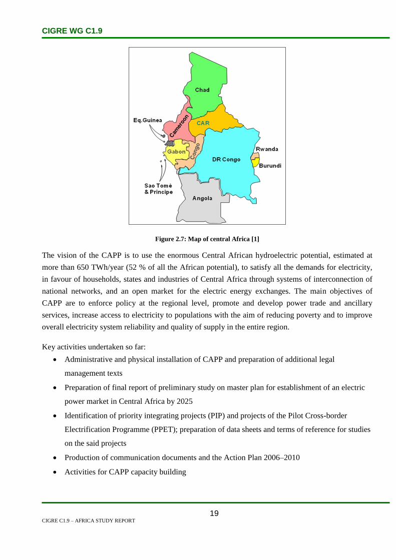
CIGRE WG C1.9
CIGRE C1.9 – AFRICA STUDY REPORT
19
Figure 2.7: Map of central Africa [1]
The vision of the CAPP is to use the enormous Central African hydroelectric potential, estimated at
more than 650 TWh/year (52 % of all the African potential), to satisfy all the demands for electricity,
in favour of households, states and industries of Central Africa through systems of interconnection of
national networks, and an open market for the electric energy exchanges. The main objectives of
CAPP are to enforce policy at the regional level, promote and develop power trade and ancillary
services, increase access to electricity to populations with the aim of reducing poverty and to improve
overall electricity system reliability and quality of supply in the entire region.
Key activities undertaken so far:
Administrative and physical installation of CAPP and preparation of additional legal
management texts
Preparation of final report of preliminary study on master plan for establishment of an electric
power market in Central Africa by 2025
Identification of priority integrating projects (PIP) and projects of the Pilot Cross-border
Electrification Programme (PPET); preparation of data sheets and terms of reference for studies
on the said projects
Production of communication documents and the Action Plan 2006–2010
Activities for CAPP capacity building

CIGRE WG C1.9
CIGRE C1.9 – AFRICA STUDY REPORT
20
Next key activities planned:
Preparation of feasibility studies on two PIP projects and four PPET projects
Adoption of technical, legal, commercial and regulatory instrumentsfor the regional electric
power market
Organization of a Power Forum on projects to establish a regional electric power market
Some CAPP projects are already underway and are in various stages of completion. There are eight
key projects and these are elaborated on below.
Table 2.4: Eight key projects

CIGRE WG C1.9
CIGRE C1.9 – AFRICA STUDY REPORT
21
2.6 Northern African Power Pool
The Arab Maghreb Union (UMA) countries are grouped within COMELEC (Comité
Maghrebin de l’Electricité).
Egypt is connected to UMA countries through the 220 kV Libya-Tunisia interconnection.
Egypt is also connected to the Middle East through 500-kV/400-kV Egypt-Jordan
interconnection.
Finally, Egypt-Libya-Tunisia-Algeria-Morocco (ELTAM) interconnection is being linked to
European electricity system through Morocco-Spain interconnection.
It forms the southern part of the future Mediterranean Electricity Ring (MEDRING).
Figure 2.8: Northern Africa Power Pool
Source http://www.dlr.de/tt/trans-csp

CIGRE WG C1.9
CIGRE C1.9 – AFRICA STUDY REPORT
22
2.7 Special Sessions Timeline
The following chapter shows a timeline of Cigre and other relevant meetings attended, which provided
to the construction of this report.
2004 CIGRE General Session
Study Committee C1 decided that the work of the working group should focus on countries/electric
utilities in the African continent
2004 Review of 1985 UPDEA/CIGRE Symposium
At the symposium the following topics were discussed
Electricity generation and the national energy policies of developing countries
Low power isolated systems and developing of interconnections
Technical developments
General constraints affecting the development in developing countries
Symposium
Electric Power System in Developing Countries
Dakar, Senegal, Nov 1985
Was organized by:
UPDEA (Mr Paul Apandina – Chairman)
CIGRE Study Committee 37 (Mr N Vigar – Norway)
CIRED (International Conference on Electricity Distribution)
SENELEC
Summary was captured in Electra edition 107 of July 1986.
304 Participants from 41 Countries participated, including 19 African Countries.
Findings from the conference:
More information exchange needed between developed and developing countries
Low access to electricity in Africa (DRC – 60 million people only 6% have electricity,
Wide intention to use pre-payment systems
Reliability: Rural – One line, Industry (n-1), Can use backup solutions for critical loads
Interconnection can improve reserve margin needs
Exchange of masterplan info between countries
Electricity to remote villages with 10 KVA load ->

CIGRE WG C1.9
CIGRE C1.9 – AFRICA STUDY REPORT
23
11 kV/LV at house with small trfrs
Young engineers from industrialized countries can learn from working in developing countries,
as they will not have such opportunity otherwise
Skills development from school level, involve developed countries in sharing information,
involve younger and operational staff during construction phase
For economic efficiency, countries should create joint centres of excellence and power training
institutes
Solutions from developed countries must be tailored to African conditions
Financing usually complex, and need for local wealth creation in countries and hence simpler
self-financing schemes
2005 Review of IEEE Power and Energy paper by Bai K. Blyden and Innocent E. Davidson
In Africa, electricity demand exceeds supply. With a population of 805 million (690 million in
sub-Sahara), only 10% are grid-connected (urban dwellers), and over 90% are not served (rural)
or nongrid-connected.
Africa uses about 3% of the world’s electricity but accounts for 13.4% of the population and
15% of land area.
The largest consumer of electricity is the mining sector.
South Africa, the most electrified African country, is 70% grid-connected, 30% nongrid or not
served.
In Nigeria, easily the largest electricity market with a population of over 126.9 million people,
less than 40% of them have access to electricity.
Every facet of human development is woven around a sound and stable energy supply regime.
The emerging picture for Africa’s critical regional power bases are: hydro power in Inga, DRC,
and Central Africa with an untapped 39 000-MW capacity.
Geothermal resources in the Rift Valley region, East Africa with an untapped 2 000–3 000
MW-potential.
Paris 2006 and Osaka 2007 Meeting
Feedback was received at both these Cigre sessions, after presentations made by C1.9 representatives.
At Paris 2006 Riaz Vajeth provided an overview of Africa’s Power sector highlighting the following:
Africa population 915 million (2006 E)
Generation 94 898 MW (2001). Energy production 338 485 GWh (2001)

CIGRE WG C1.9
CIGRE C1.9 – AFRICA STUDY REPORT
24
Africa is fairly endowed with significant energy resources for electricity generation, but they
are unevenly distributed.
Oil and gas reserves in North Africa and the Gulf of Guinea; oil or gas fields in other areas; e.g.
Sudan, Ethiopia, Chad, Mozambique, Namibia, and Tanzania.
Hydropower potential in Central and Eastern Africa with highest potential in DRC, Ethiopia
and Cameroon.
Coal deposits in Southern Africa, but predominantly South Africa with 90% of the 55 billion
tons total reserves.
Geothermal energy in East Africa region (Kenya, Ethiopia and Djibouti).
Highest wind power potential in North Africa (Morocco and Egypt) and Southern Africa.
Sourced from, Mr. P. Niyimbona UN Economic Commission for Africa
Riaz also mentioned the benefits to be expected from developing interconnections and operating power
pools which include the following:
reduction capital and operating costs through improved coordination among power utilities;
optimisation of generation resources with large units;
improved power system reliability with reserve sharing;
enhanced security of supply through mutual assistance;
improved investment climate through pooling risks;
coordination of generation and transmission expansion;
increase in inter-country electricity exchanges; and
development of a regional market for electricity.
One of the comments received at Osaka meeting was to include information on energy efficiency and
renewable energy initiatives. These are included in relevant country chapters that follow, but is not
exhaustive.
2007 SAPP Meeting in Livingstone, Zambia
South African team met with Planning Managers from all SAPP countries and presented their
work
Obtained contact list of the SAPP planning personal
Obtained agreement from countries to participate in workgroup and to update their respective
country data

CIGRE WG C1.9
CIGRE C1.9 – AFRICA STUDY REPORT
25
2008 UPDEA Conference in Nairobi
Riaz Vajeth made a presentation on C1.9 work at this conference.
Union of Produces, Conveyors and Distributors of Electric Power in Africa
This is the largest gathering of power utility executives and technical experts from Power
Companies across Africa
Attended by Riaz Vajeth and Andy Bitcon
Presentation done to an audience of 400 delegates representing 40 countries across Africa
Got indication from UPDEA Chairman for support for C1.9 work
Handed out draft country papers and asked countries to update these.
Became aware that UPDEA is updating the Africa Grid Map, and this task is almost complete
Big focus on improving access to electricity to all people in Africa
Was made aware of previous UPDEA/CIGRE collaboration, 1985 Symposium
2008 Africa Power & Electricity Congress Johannesburg
Energy development in Africa
Regulation and Policy
Finance and Funding
Options for alternative and renewable Energy
Initiatives for energy efficiency
The role of IPPs
Oil and gas markets – fuelling growth in Africa
Ensuring sustainable developments
Nuclear energy – the fastest growing future power source
Power pools and electricity distribution
Innovative solutions for transmission and distribution
2009 Feedback on Parallel Session on WG C1.9 Issues at Cigre 6th
Southern African Regional
Conference in Cape Town 19 August 2009
30 delegates from the Main Conference attended the Parallel Session
Presentations covered Planning issues in the following African Countries:
o South Africa
o Namibia

CIGRE WG C1.9
CIGRE C1.9 – AFRICA STUDY REPORT
26
o Sudan
o Côte d’Ivoire
o Morocco, Algeria, Tunisia, Libya and Egypt
Other presentations:
o Geo-based load forecasting
o Long term network master plans
2011 Special meeting with group of contributing engineers and editor
Riaz Vajeth convened a meeting with 10 newly qualified graduate engineers and briefed them on an
assignment to capture final updated information on all African countries. Each engineer was assigned 5
to 6 countries. They are Brenen-Lee Wallace Govender (co-ordinator), Ruaan Nel (Lead assistant to
Riaz for technical content), Chandresh Juggernath, Zane Evan, Ndangi Muthadi, Vhuhwavho Mungai,
Junaid Alli, Ameeth Nathoo, De Wet Visser and Clinton Ashley Chetty. The workgroup would like to
thank this group for the noteworthy efforts in short a time frame. They were also able to get some
exposure regarding CIGRE activities.
Ruaan also assisted Riaz in getting the final editing done, which was completed by Monica Kirsten
from the University of Stellenbosch.
In 2011, Kevin Leask presented an uodate in Brazil session in April 2011.
In 2012, Riaz Vajeth presented at Cigre Paris session. The issue of solar photovoltaic power was
highlighted as an area of intrest, which could provide a solution for electrification of remotes parts in
Africa and rural areas. Some brief information is included here as chapter 3, which can be built upon in
futures updates of this report. There was also support for marketing this document and for collection of
comments by inserting links in the CIGRE, UPDEA, World Energy Council, and financial institutions
websites like AFDB and World Bank. There was also support for arranging a joint UPDEA & CIGRE
workshop.

CIGRE WG C1.9
CIGRE C1.9 – AFRICA STUDY REPORT
27
3. Solar Power
Solar Power is purely the conversion of sunlight into electricity. There are various techniques
in order to extract this energy and provide basic power into the households of millions of people in
Africa. The conversion process can adopt of one two techniques, namely Photovoltaic (PV) or
concentrated solar power (CSP).
PV technology is a solar cell which is a semiconductor that is able to harness the sunlight and convert
to Direct Current. The use of an inverter converts the DC to AC which most of the household
applications utilizes.
CSP technology is mainly used in large scale operations often feeding a grid and supplying millions of
households. This type of system uses numerous mirrors or lenses that reflect light onto a centralised
tower. The lenses / mirrors are parabolic in order to direct maximum amount of sunlight onto the
tower. The newer types of mirrors are extremely efficient as they rotate and align themselves to the
rays of the sun.
Figure 3.1: Schematic Diagram of CSP process
The tower consists of a tank filled with water and the reflected sunlight heats the water into steam. A
steam turbine is connected to the tower and the water generated steam spins the blades of the turbine,
the output of the steam turbine is connected to a generator, which is utilized to pump this energy into

CIGRE WG C1.9
CIGRE C1.9 – AFRICA STUDY REPORT
28
the national grid.
Alternative sources of Electricity are becoming important in Africa because of capacity shortage and
environment demands growing each year. Solar power is an ideal option for renewable energy in
Africa. The capital costs for solar photovoltaic is fast decreasing and becoming more affordable for
production of power in remote and rural areas in Africa, and in many cases can displace diesel
generators.
Figure 3.2: PV array
Source: http://www.charcoalproject.org/2010/12/nyt-energy-poverty-on-the-agenda-for-2011/
Electricity from renewable sources would be beneficial in terms of security (illumination), hot water
readily available, business stores opening longer hours for trade, education levels increases as scholars
become computer literate, various health related problems addressed in clinics due to equipment power
by solar, etc.
A case study conducted in Ghana revealed a better quality of life, high attendance in schools, improved
health, improved agricultural production and increased productivity.

CIGRE WG C1.9
CIGRE C1.9 – AFRICA STUDY REPORT
29
4. Algeria
4.1 Electricity Industry Structure
4.1.1 The Algerian Network
Algeria’s state-owned power company, Sonelgaz, generates and distributes electricity and natural gas
to the entire country. Established in 1969, Sonelgaz has a maximum demand of 6 468 megawatts and
is made up of 22 subsidiaries and 20 837 employees, as of December 2006. The company is
responsible for network management, maintenance, engineering, conversion, planning studies,
elaboration of tender documents, supervision and training. Some electricity related statistics are shown
in Table 2.1
Table 4.1: System Statistics – Algeria
Installed Capacity by Type of Generation (MW) – 2008
Thermal 8 055
Steam Turbines 2 740
Gas Turbines 4 490
Combined Cycle 825
Diesel 216
Hydro 230
Renewables
Others
Total 8 501
Yearly Generation by Type (GWh) – 2008
Thermal 39 427
Steam Turbines 13 384
Gas Turbines 20 339
Combined Cycle 5 704
Diesel 276
Hydro 283
Renewables
Others
Total 39 986
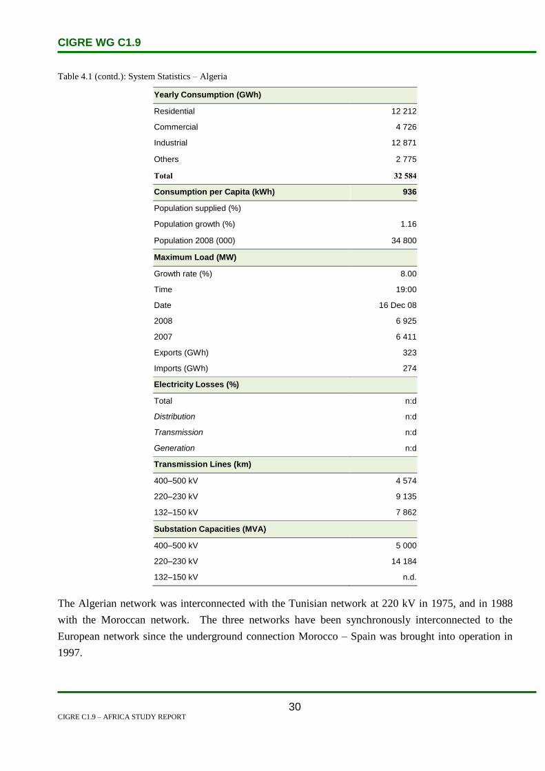
CIGRE WG C1.9
CIGRE C1.9 – AFRICA STUDY REPORT
30
Table 4.1 (contd.): System Statistics – Algeria
Yearly Consumption (GWh)
Residential 12 212
Commercial 4 726
Industrial 12 871
Others 2 775
Total 32 584
Consumption per Capita (kWh) 936
Population supplied (%)
Population growth (%) 1.16
Population 2008 (000) 34 800
Maximum Load (MW)
Growth rate (%) 8.00
Time 19:00
Date 16 Dec 08
2008 6 925
2007 6 411
Exports (GWh) 323
Imports (GWh) 274
Electricity Losses (%)
Total n:d
Distribution n:d
Transmission n:d
Generation n:d
Transmission Lines (km)
400–500 kV 4 574
220–230 kV 9 135
132–150 kV 7 862
Substation Capacities (MVA)
400–500 kV 5 000
220–230 kV 14 184
132–150 kV n.d.
The Algerian network was interconnected with the Tunisian network at 220 kV in 1975, and in 1988
with the Moroccan network. The three networks have been synchronously interconnected to the
European network since the underground connection Morocco – Spain was brought into operation in
1997.

CIGRE WG C1.9
CIGRE C1.9 – AFRICA STUDY REPORT
31
Trading between the three Maghreb countries has been carried out on the basis of annual of specific
contracts. It is also important to point out that ONE and SONELGAZ are external operators on the
Spanish electricity market. They buy and sell energy on the basis of bilateral contracts and/ or directly
participate with the joint Spanish-Portuguese market operator, MIBEL.
4.1.2 Electricity Market
The Algerian government decided to progressively open the electricity market in 2002 and the
‘Electricity Law’ was approved on 5 February 2002. The main provisions of the Law, which governs
the sector of electricity, are:
The opening of the electricity sector to private investments and in particular the competitive
activities of electricity (production and supply) and natural gas, so as to achieve:
o a reduction of costs.
o an improvement in the quality of service to customers.
o a creation of competition in the electricity sector.
Investments: any investor who so wishes, can produce electricity with a simple authorization.
For distribution, a system of concessions is in place.
Public Service: the state remains in charge of ensuring the quality of public service.
Network access: access to transmission and distribution networks, regulated natural
monopolies, is guaranteed for all.
In order to ensure that there is no discrimination between operators, the following bodies have been
created:
An Independent System Operator.
A Market Operator.
A Regulatory Commission for Electricity and Gas.
The latter, which must be independent and autonomous, has the following mission:
To control the public service.
To advise public authorities on the organization of the market.
To control and monitor compliance with the regulations by the operators.
4.1.3 Electricity Market Opening
Progressive market opening is an objective to be reached consistently with the provisions contained in
the Law of 5 February 2002. The following reforms have been undertaken or are in progress:
The restructuring of SONELGAZ into a holding company with subsidiaries responsible for
specific activities (legal separation) since 1 January 2004.
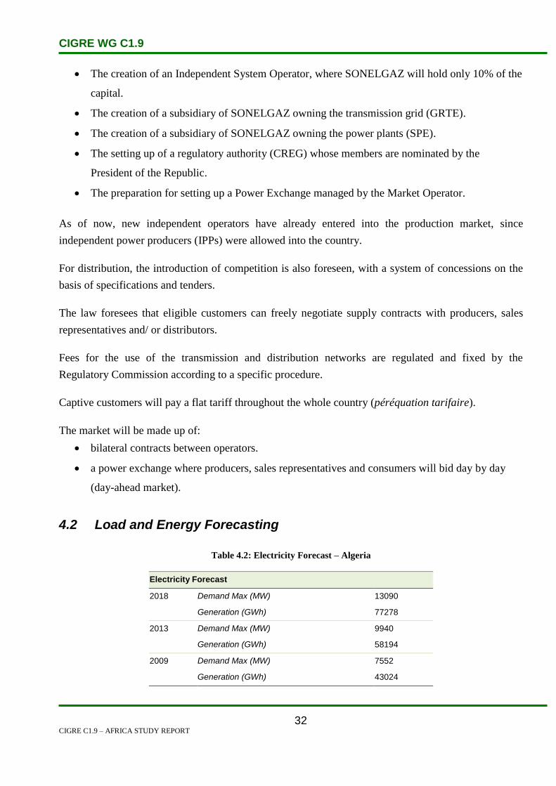
CIGRE WG C1.9
CIGRE C1.9 – AFRICA STUDY REPORT
32
The creation of an Independent System Operator, where SONELGAZ will hold only 10% of the
capital.
The creation of a subsidiary of SONELGAZ owning the transmission grid (GRTE).
The creation of a subsidiary of SONELGAZ owning the power plants (SPE).
The setting up of a regulatory authority (CREG) whose members are nominated by the
President of the Republic.
The preparation for setting up a Power Exchange managed by the Market Operator.
As of now, new independent operators have already entered into the production market, since
independent power producers (IPPs) were allowed into the country.
For distribution, the introduction of competition is also foreseen, with a system of concessions on the
basis of specifications and tenders.
The law foresees that eligible customers can freely negotiate supply contracts with producers, sales
representatives and/ or distributors.
Fees for the use of the transmission and distribution networks are regulated and fixed by the
Regulatory Commission according to a specific procedure.
Captive customers will pay a flat tariff throughout the whole country (péréquation tarifaire).
The market will be made up of:
bilateral contracts between operators.
a power exchange where producers, sales representatives and consumers will bid day by day
(day-ahead market).
4.2 Load and Energy Forecasting
Table 4.2: Electricity Forecast – Algeria
Electricity Forecast
2018 Demand Max (MW) 13090
Generation (GWh) 77278
2013 Demand Max (MW) 9940
Generation (GWh) 58194
2009 Demand Max (MW) 7552
Generation (GWh) 43024

CIGRE WG C1.9
CIGRE C1.9 – AFRICA STUDY REPORT
33
4.3 Planning and Design Criteria
The main technical criterion for transmission system development is the N-1 security criterion. It is
mostly related to the loss of single circuit, transformer or generator, when after the occurrence of a
fault event the following consequences are to be avoided:
thermal overloading of branches,
voltage deviations above a permitted range,
loss of stability,
loss of load,
interruption of power transits, and
disturbance spreading over the power system.
4.4 Planning Approaches and Methods
N-security conditions
The basic assumptions related to the N criterion of the transmission network are:
The rating limits of transmission lines should be intended as maximum permanent currents.
In normal operating conditions, no overload of the transmission network is allowed.
No generator will be above its continuous reactive capability with possible restrictions decided
by the planner to account for operational constraints.
The loads are represented as constant active and reactive powers.
In normal operating conditions a long-term overload of transformers up to 10% of nominal
rating is allowed. A short term overload (less than 15 minutes) is allowed up to 20%.
Maximum and Minimum Operating Voltages.
For the transmission system generally, unless otherwise specified, the maximum operating
voltages are as follows:
o For 400 kV network maximum voltage is 428 kV.
o For 220 kV network maximum voltage is 235.4 kV.
o For 150 kV network maximum voltage is 159 kV.
o For 90 kV network maximum voltage is 95.4 kV.
o For 60 kV network maximum voltage is 63.6 kV.
The minimum operating voltages values are as follows:
For 400 kV network minimum voltage is 372 kV.

CIGRE WG C1.9
CIGRE C1.9 – AFRICA STUDY REPORT
34
For 220 kV network minimum voltage is 204.6 kV.
For 150 kV network minimum voltage is 141 kV.
For 90 kV network minimum voltage is 84.6 kV.
For 60 kV network minimum voltage is 56.4 kV.
Operating Frequency
The nominal frequency of North African countries is 50 Hz and its permissible variation range
under automatic generation control (AGC) is 50 ± 0.05 Hz.
Under normal operating condition the maximum permissible variation range is 50 ± 0.2 Hz.
N-1 Conditions
The following criteria are applied under N-1 contingency conditions:
The transmission system should be planned such that reasonable and foreseeable contingencies
do not result in the loss or unintentional separation of a major portion of the network or the
separation from the regional interconnected system.
During contingency conditions, a temporary overload of the transmission lines is allowed up to
10%.
A temporary overload of transformers is allowed in emergency conditions up to 20%
continuously during peak hours.
The maximum post-transient voltage deviation is 10%.
For transmission system generally, unless otherwise specified, the maximum operating voltage values
are as follows:
For 400 kV network maximum voltage is 440 kV.
For 220 kV network maximum voltage is 242 kV.
For 150 kV network maximum voltage is 162 kV.
For 90 kV network maximum voltage is 97 kV.
For 60 kV network maximum voltage is 65 kV.
The minimum operating voltage values are as follows:
For 400 kV network minimum voltage is 340 kV.
For 220 kV network minimum voltage is 187 kV.
For 150 kV network minimum voltage is 138 kV.
For 90 kV network minimum voltage is 83 kV.

CIGRE WG C1.9
CIGRE C1.9 – AFRICA STUDY REPORT
35
For 60 kV network minimum voltage is 55 kV.
Operating range frequency:
During N-1 contingency conditions, the maximum and minimum permissible frequencies are
50.4 Hz and 49.6 Hz respectively.
In the case of a severe incident, the maximum and minimum permissible frequency limits are
52 Hz and 47.5 Hz respectively.
Transmission Network Planning Probabilistic Approach.
The probabilistic approach is seldom used in planning studies directly by the concerned transmission
system operators (TSOs) or vertically integrated undertakings (VIUs). However, the probabilistic
approach is being widely used in interconnection studies among the North African Countries (e.g., the
MEDRING and the ELTAM studies).
Unless specific data is provided, the basic assumptions adopted concerning the unavailability of the
transmission system, are given in the Table 4.3 below.
Table 4.3: Line Forced Unavailability Rate
Voltage Level
[kV]
Unavailability Rate
[p.u./100 km]
500–400 0.005
220 0.0025
150–90 0.005
As no reliability data on the transformers is usually available, standard hypotheses for these values are
assumed. It is assumed that the transformers have an availability of 99.5%.
Also for reactors and capacitors, records on their reliability are not normally available; hence, in this
case too, standard hypotheses for these values are adopted. More specifically, it is assumed that the
reactive compensation equipment has an availability of 99.5%.
Three different weather conditions, Normal, Bad and Stormy, are considered and, unless otherwise
specified, the parameters used to simulate the weather effect are set out in Table 4.4 below:
Table 4.4: Parameters of Weather Model
Weather Conditions Hours Ratio
[p.u.]
Coefficients
[p.u.]
Normal 0.9667 1.0

CIGRE WG C1.9
CIGRE C1.9 – AFRICA STUDY REPORT
36
Bad 0.03 10.0
Stormy 0.003 15.0
As an indicator of the system adequacy, the annual value of Expected Energy Not Supplied (EENS)
due to unavailability in the transmission system and/or generation considering the constraints
represented by the transport capacities of the lines and active power limits of the power plants is used.
A threshold value 10-4 p.u. for the EENS index related to insufficiency of the transmission system due
to a reduction in the transmission capacity of the network is assumed.
Economic Evaluation in Transmission-Generation Planning
The price of EENS for an economic evaluation can vary from 0.5 USD/kWh up to 2 USD/kWh.
The generation margins and the loss of load probability adopted for the reliability study are the
following:
Minimum generation margin reserve: 20%.
Loss of load probability (LOLP): < 48 hrs/year.
4.5 Specific Technical Issues
Algeria has an extensive AC network, covering both the densely populated coastal areas and also the
unpopulated centre of the country, where the gas and oil industries are. According to Sonelgaz, the
total length of its transmission network is approximately 18 000 km. This includes lines with voltage
levels down to 60 kV. The length of the 400 kV transmission lines sum up to less than 1 300 km.
Sonelgaz are currently making strong efforts to upgrade these grid lines. Reinforcements of cross-
border connections with neighbouring countries Morocco, Tunisia and Libya, also on the basis of
400 kV technology, are progressing. Algeria also has plans for submarine electricity links with its
European neighbours on the other shore of the Mediterranean.[1]
4.6 Financing Issues
Transmission investments are mostly financed through transmission fees, loans, internal sources and
very few by private investors.
Economic Criteria (capital investment, internal rate of return (IRR), net present value (NPV)), in
transmission network planning are applied. In the economic evaluations, the reduction in the cost of
the losses is usually estimated, but additional benefits related to the reduction of congestion costs are
also taken into account as well as the increase of transmission service revenues.
Generally, the TSOs or the VIUs have not defined the cost of EENS and the applied values are agreed

CIGRE WG C1.9
CIGRE C1.9 – AFRICA STUDY REPORT
37
for each study among the local experts and also taking into account the experience of the Consulting
companies, whenever they are involved in the execution of transmission system studies. Usually, the
undelivered electricity costs across North Africa range between 0.5 and 2USD/kWh.
Market-oriented transmission investments (merchant lines) and investments from a regional
perspective are not applied. National transmission networks are mainly planned according to
technical considerations and economic rationalization of new investments.

CIGRE WG C1.9
CIGRE C1.9 – AFRICA STUDY REPORT
38
4.7 Human Resources
Sonelgaz controls the generation, transmission, and distribution of electricity in Algeria. In July 2002,
Sonatrach and Sonelgaz formed a joint venture, to pursue the development of alternative electricity
sources, including solar, wind, and biomass. Since 2002, there has been considerable private
investment in new electricity generating capacity in Algeria.
AEC (Algerian Energy Company) contracted with Anadarko and General Electric to build the
country’s first privately financed, gas-fired power plant at Hassi Berkine. In August 2003, France’s
Alstom agreed to construct a 300-MW power plant at F’Kirina. Canada’s SNC-Lavalin won a contract
in July 2003 to design and build an 825-MW, combined cycle power plant in Skikda. In 2004, SNC-
Lavalin also won a tender to build a 1 200-MW, combined cycle power plant in Tipasa. In early 2005,
Siemens announced that it would build a 500-MW, gas-fired plant in Berrouaghia: tje caility should
become operational by the end of 2006.[2]
Only 6.6% of the population has received higher education at the university level. Illiteracy is high,
32% of the population, mostly women and people living in rural areas.
4.8 References
1. http://www.wupperinst.org/uploads/tx_wiprojekt/Algeria_final_report.pdf, pages 27 and 28
2. http://www.mbendi.com/indy/powr/af/al/p0005.htm

CIGRE WG C1.9
CIGRE C1.9 – AFRICA STUDY REPORT
39
5. Angola
5.1 Electricity Industry Structure
Figure 5.1: Map of Angola [1]
Angola is located in sub-Saharan Africa as shown in Figure 5.1. The northern part of the country is
bordered by the Democratic Republic of the Congo while the eastern part is bordered by Zambia. The
southern part of the country is bordered by both Namibia and Botswana. Angola is still rebuilding
infrastructure destroyed during the country’s 27-year civil war that came to an end in 2002. Although
the country is beginning to see growth and stability, challenges persist. Around 70% of the population
still lives on less than US$1/day; the World Bank ranks Angola as one of the most difficult places in
the world to do business as a result of bureaucracy, and there are persistent allegations of lack of
transparency in public finance [1].
The Ministry of Energy and Water (MINEA) governs the electricity sector. In principle, the national
power utility, Empresa Nacional de Electricidade (ENE), is responsible for generation, transmission
and distribution throughout the country (excluding distribution in the capital city of Luanda). ENE
operates three different power systems – the northern, central and southern systems – each stretching
in an easterly direction from the ports of Luanda, Lobito and Namibe respectively. The other main
player in the electricity supply industry (ESI) is Empresa de Distribução de Electricidade de Luanda
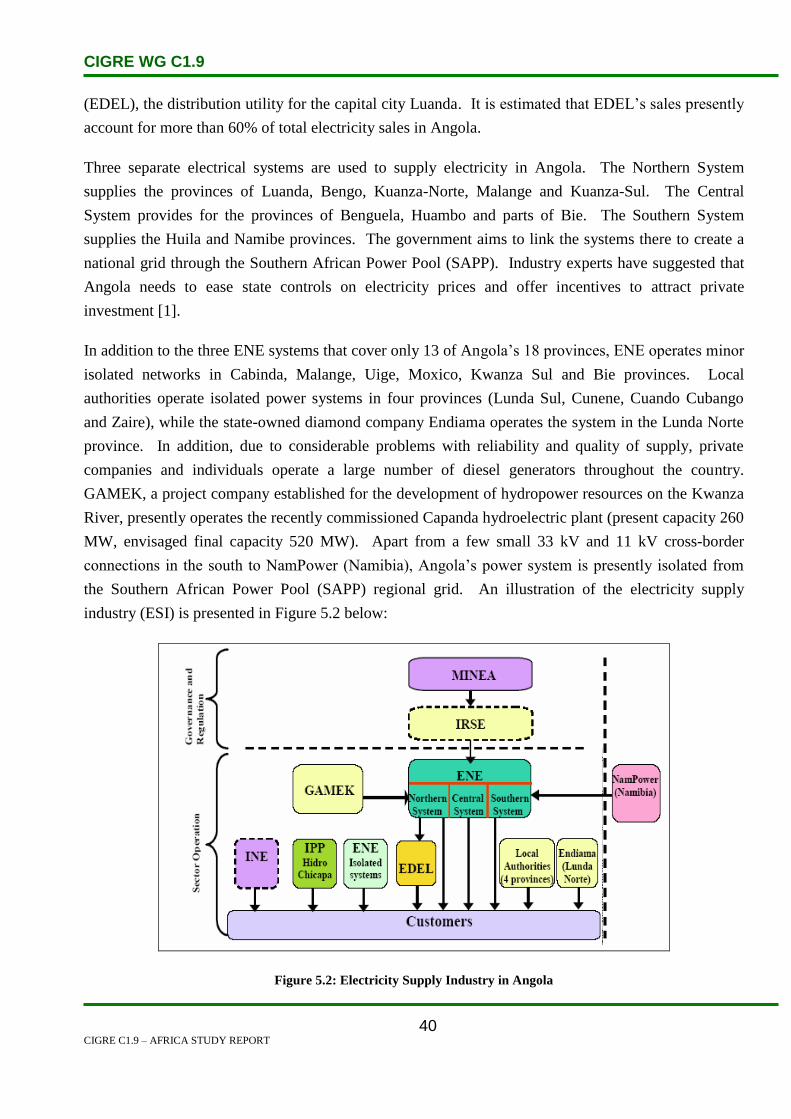
CIGRE WG C1.9
CIGRE C1.9 – AFRICA STUDY REPORT
40
(EDEL), the distribution utility for the capital city Luanda. It is estimated that EDEL’s sales presently
account for more than 60% of total electricity sales in Angola.
Three separate electrical systems are used to supply electricity in Angola. The Northern System
supplies the provinces of Luanda, Bengo, Kuanza-Norte, Malange and Kuanza-Sul. The Central
System provides for the provinces of Benguela, Huambo and parts of Bie. The Southern System
supplies the Huila and Namibe provinces. The government aims to link the systems there to create a
national grid through the Southern African Power Pool (SAPP). Industry experts have suggested that
Angola needs to ease state controls on electricity prices and offer incentives to attract private
investment [1].
In addition to the three ENE systems that cover only 13 of Angola’s 18 provinces, ENE operates minor
isolated networks in Cabinda, Malange, Uige, Moxico, Kwanza Sul and Bie provinces. Local
authorities operate isolated power systems in four provinces (Lunda Sul, Cunene, Cuando Cubango
and Zaire), while the state-owned diamond company Endiama operates the system in the Lunda Norte
province. In addition, due to considerable problems with reliability and quality of supply, private
companies and individuals operate a large number of diesel generators throughout the country.
GAMEK, a project company established for the development of hydropower resources on the Kwanza
River, presently operates the recently commissioned Capanda hydroelectric plant (present capacity 260
MW, envisaged final capacity 520 MW). Apart from a few small 33 kV and 11 kV cross-border
connections in the south to NamPower (Namibia), Angola’s power system is presently isolated from
the Southern African Power Pool (SAPP) regional grid. An illustration of the electricity supply
industry (ESI) is presented in Figure 5.2 below:
Figure 5.2: Electricity Supply Industry in Angola

CIGRE WG C1.9
CIGRE C1.9 – AFRICA STUDY REPORT
41
The ESI is basically a monopoly industry, although other players have defined roles in certain
geographical areas or for certain specific applications (e.g. GAMEK). No plans exist at this stage to
change the ESI structure into a more competitive market arrangement, although an ESI reform seminar
in October 2004 recommended that a plan be developed for institutional and market reform of the
sector. Due to Angola’s transmission system not being connected to neighbouring countries, Angola is
not an operating member of the SAPP. This would change if the Westcor project between the
Democratic Republic of Congo, Angola, Namibia, Botswana and South Africa is realized. This is
basically the proposed development of a western transmission corridor through the countries
mentioned. However, this project has encountered political difficulties in reaching agreement between
the countries involved and these will need to be resolved for the project to progress.
The ESI presently operates under several Acts of Parliament. The most important is the Lei Geral de
Electricidade, Lei No.14 – A/96 of 31 May 1996 (General Law of Electricity). The Law sets out the
tariff system and pricing principles, establishes the National Energy Fund to facilitate the
electrification of the country, and sets up a concessionaire system for regulating the entry of the
private sector into the ESI. This law also enabled the establishment of an electricity regulator, the
Institute for Electricity Regulation (IRSE), formally created in 2002. A Multi-sector Rehabilitation
and Reconstruction Programme (MRRP) is to be implemented in two phases.
5.2 Load and Energy Forecasting
The electrical system in Angola is disjointed and is undergoing repairs from damage incurred during
many years of war. While a load study may predict load growth as a trend of gradual increases over
time, the actual increases will most likely come in discrete steps as transmission lines become
reconnected or substation transformers are repaired. Load growth in Luanda will most likely occur as
a gradual increase as the electricity supply becomes more reliable and economic activity increases. In
the rest of the country, the increases in load growth will most likely occur in discrete steps as
communities become reconnected to the system, generation is repaired and electricity supply becomes
available. This will be especially true of municipalities that have distribution in place and are waiting
to reconnect to the system. Municipalities that have their own thermal generation may want to shut it
down to benefit from the less expensive power generated by combined hydro and thermal generators.
Discrete step increases will also be the result of new industrial loads from new facilities being built or
the expansion of existing factories [2].
In developing the following assessment of system expansion, consultants relied on several sources of
information. MINEA issued a development strategy of the electric sector in July 2002. The study
forecasts increases in generation (GWh) and capacity (MW) coming on line for 2006, 2011 and 2016.
Note that although well written, this Electric Sector Strategy suffers from a lack of data, no
quantification of market demand factors, isolation from economic indices or strategies and, therefore,

CIGRE WG C1.9
CIGRE C1.9 – AFRICA STUDY REPORT
42
its projections may be unrealistic. Capacity expansion plans were also determined from information
gathered during meetings held by consultants while in country in June of 2003, and are presented in
the Emergency Response Study for generation capacity expansion and transmission line construction.
The expansion plans reported from the meeting of June 2003 are a compilation of projects already in
construction or tendering, and did not appear to be part of an overall balanced strategy for the country.
ENE has already expressed concern about reconnecting Huambo, a former industrial centre, because
the generation capacity in the Central System, particularly at Biopio, will not be sufficient to support
the increased load, while there is an excess of generation in the North System. In Lunda Sul, a 20 MW
hydroelectric plant is being built by a private investor (Alrosa Mining) to provide 18 MW of power to
the local diamond mine and 2 MW to the surrounding area. Increased economic activity supporting
the diamond mine may require additional generation, which can be accommodated with careful
planning [2].
Table 5.1 shows the annual peak demand growing at 12% p.a. (Consultant’s estimates).
Table 5.1: Angola Annual Peak Demand, Growth at 12% p.a. [2]
2003 2006 2011 2013 2014 2016
North
Installed Capacity, MW 358 643 643 643 643 643
Peak Load, MW 260 359 537 626 676 789
Excess (Deficit), MW 98 284 106 17 (33) (146)
Central
Installed Capacity, MW 37 121 121 121 121 121
Peak Load, MW 37 47 76 91 98 114
Excess (Deficit), MW 0 75 45 31 23 7
South
Installed Capacity, MW 27 158 158 158 158 158
Peak Load, MW 27 34 56 65 70 82
Excess (Deficit), MW 0 124 102 93 88 76
Other
Installed Capacity, MW 28 48 48 48 48 48
Peak Load, MW 28 35 52 60 65 76
Excess (Deficit), MW 0 13 (4) (12) (17) (28)
Total
Installed Capacity, MW 450 970 970 970 970 970
Peak Load, MW 352 475 721 842 910 1061
Excess (Deficit), MW 98 496 249 128 60 (90)
Energy, GWh @65% LF 2004 2703 4105 4797 5181 6043
MINEA Projection 2804 4007 5506

CIGRE WG C1.9
CIGRE C1.9 – AFRICA STUDY REPORT
43
5.3 Planning and Design Criteria
Figure 5.5 shows energy mix of hydro, thermal grid and thermal isolated. Hydroelectric facilities
generate more than two-thirds of Angola’s electricity. The Matala dam, which began operations in
2001 on the Cunene River, is the main source of electricity in south west Angola. The Cambambe
dam (180 MW) on the Kwanza River, the Mabubas dam (17.8 MW) on the Dande River, and diesel
generators, are the main sources of electricity generation in the north of the country. A 24 MW dam is
being built by a diamond company, Catoca, on the Tchicapa River in north eastern Angola, and the
construction of a 600 MW dam in the Uije province was announced in June 2004 [3].
The Emergency Response Study focused on rehabilitation and repairs of installed generation and
transmission. There will be an excess of generation capacity after units 1&2 of Capanda Dam come on
line in 2004. Repairs to transmission lines, as well as the completion of new transmission lines
planned for supplying Luanda, will greatly improve the reliability of the system, particularly in the
north. Planning for the development of an integrated system should commence in the mid-term so that
the first steps toward the overall system can begin when the rehabilitation programme is coming to a
close. Integral to this planning is a detailed load forecast, a stability study and a reliability study. The
results of these studies are necessary as a foundation for the plans to connect the North System to the
Central and South Systems, as well as to connect the Isolated Systems and the provincial capitals [2]
The construction of a hydroelectric facility at Capanda on the Kwanza River has been partially
completed. Work on the 520 MW plant began in the mid-1980s, but was suspended due to the civil
war. The first of four planned hydraulic turbines began generating electricity in January 2004; a
second turbine is expected to be operational in April 2005. The completed Capanda project will nearly
double Angola’s electricity generating capacity. The government plans to create a national grid,
linking the three regional electricity sectors, and establishing linkages with neighbouring countries.
The additional generating capacity from the rehabilitation and greenfields projects, together with the
national grid system, could enable Angola to become an exporter of electricity to neighbouring
countries [3].
Angola employs a deterministic approach for generation planning and maintains a reserve margin
greater than 15%.
In terms of transmission planning, the N-1 criterion is employed in most cases.

CIGRE WG C1.9
CIGRE C1.9 – AFRICA STUDY REPORT
44
Energy Mix
62%
30%
8%
Hydro (Thermal grid) Thermal (isolated)
Figure 5.3: Energy Mix
5.4 Planning Approaches and Methods
As the power sector emerges from the rehabilitation phase, there will be a renewed emphasis on long
term planning and the development of a modern integrated power sector. In this regard, there will be
the co-ordinated development of hydro and natural gas generation based on a least cost strategy which
reflects national energy policy goals. The Government of Angola (GOA) will implement the
Electricity Law allowing for eventual private sector participation in new generation and in both the
management of ENE and EDEL. An electricity regulator will be established with the authority to issue
licenses and approve tariffs and in general improve the transparency of the sector. The GOA in
conjunction with the two utilities, ENE and EDEL, will seek to improve their commercial and financial
operation with the goal of creating self-sustaining and financially viable entities. In this regard the
GOA, through an independent regulator, will seek to reduce all subsidies and establish economically
and financially remunerative tariffs. With private sector participation and self-sustaining operations
the system will expand, providing improved access [2].
The GOA will play a critical role in leading the development and reform of the power sector in the mid
to long term. The key GOA institution will continue to be the MINEA. However MINEA will need to
evolve and grow from its current structure. The principle roles envisioned for MINEA will be:
Setting policy initiatives to drive sector reform.
Amending the legal framework for the sector as it develops.
Providing medium and long term forecasts of demand and supply, and maintaining a sector data
base.

CIGRE WG C1.9
CIGRE C1.9 – AFRICA STUDY REPORT
45
Being the lead institution in the reform and restructuring of the sector.
Economic assessment of sector issues.
Technology assessments and development of energy efficiency programmes.
Co-ordination with other GOA institutions regarding the development of energy policy.
The roles currently held by MINEA in the area of licensing would eventually be transferred to the
Regulator. Thus MINEA would be structured into two divisions: the first being Policy and Planning,
the other being Technology and Energy Management. This view of MINEA differs from that currently
held by MINEA which sees itself maintaining control over the power sector through the issuance of
licenses and concessions for the sector. Based on the above, there are several areas for TA support
which would prepare MINEA for its evolving role in the sector in the mid to long term. The TA would
build on the basic policy analysis and planning tools that were identified in the Emergency Response
Study as part of the short term TA to be provided to MINEA. The recommended TA programmes are
as follows [2]:
Private sector participation in the power sector.
Power sector restructuring strategy.
IPP development framework.
Energy efficiency programme development.
Renewable energy alternatives.
5.5 Specific Technical Issues
The following are technical issues as stated in [2]:
Only 20 per cent of the population has access to electricity.
Significant non-technical losses through illegal connections.
Significant technical losses resulting in system instability and power quality problems.
Electricity tariffs are not cost recovering and are highly subsidized, resulting in losses for both
ENE and EDEL.
Lack of system planning to focus on the longer term development of the sector.
Significant economic cost associated with the investment in standby generating capacity due to
the unreliability of the system.
Need to attract significant private investment for growth.
Inadequate management and commercial processes.

CIGRE WG C1.9
CIGRE C1.9 – AFRICA STUDY REPORT
46
Need to rationalize human resource requirements.
Need for Government of Angola (GOA) to re-allocate budgetary resources from the power
sector to the social and public services.
5.6 Financing Issues
Angola and Namibia signed a bilateral co-operation agreement in the field of energy and have
considered the development of a hydroelectric facility on the Kunene River. Two sites that have been
considered are at Epupa Falls and at the Baynes Mountains, although the Epupa Falls location has met
opposition from environmental groups and local communities. The results of a US$7 million
international feasibility study of the Epuqa Falls project indicated that the Epupa Falls site would
represent the best option economically. However, the displacement of the local Himba people coupled
with the environmentally sensitive location of the site has meant that progress has been slow.
Namibia’s NamPower believes the Epupa Falls site is the best technical and financial option and would
like to see the project in operation. [3].
The Emergency Response Study identified a future long term plan for the Western Corridor Project a
3000 MW line from Inga in the Democratic Republic of the Congo. This line may be a 765 kV AC
line or a high voltage DC line to supply power to South Africa through Namibia. This project has been
under consideration for some time by the SAPP. Within the next ten years there is significant potential
for building generation capacity for export. As stated before there is an oversupply of generation
capacity in the North System, especially when Units 3&4 of the Capanda Dam come on line. [2].
This generation capacity could be used as reserve on the system to cover scheduled and unscheduled
outages or, if there is sufficient other reserve, could be considered for export. Furthermore, there is
approximately 16 000 MW of hydro potential that awaits development. There is no tie in the
transmission system at the border with Zambia or the Democratic Republic of the Congo, nor are there
plans to build a tie at present. There is a tie to Namibia at Ondjina in Cunene Province; however, this
is a small point to point connection.

CIGRE WG C1.9
CIGRE C1.9 – AFRICA STUDY REPORT
47
Figure 5.4: More than 7000 MW hydro potential along Kwanza River
This said, the National Energy Directorate (DNE) asserts that in the highest levels of Government
there exists recognition that renewable energy will be important to Angola’s future. Although DNE’s
focus is on solar photovoltaic technologies, Angola has a large and, yet to be estimated, potential for
small and micro hydro resources. For larger hydro resources the Portuguese did extensive surveys and
modelling, reporting a potential hydro generation capacity of over 150 000 GWh/year, indicating that
the current hydro exploitation of 1 200 GWh/year represents less than 1% [2] .
5.7 Human Resources
ENE, the state-owned electric utility, is doing its own generation, transmission and distribution
planning. Some external consultants do carry out some work affecting how the network will be
expanded. The following are examples of work carried out by external consultants.
Nexant, under its contract with USAID, has been assigned the task of conducting a diagnostic
needs assessment of the energy sector in Angola. Energy is fundamental to the economic
development of the country. Currently, the majority of the population does not have accessible,
reliable supplies of energy. The objectives of this task are to determine the critical areas for
technical assistance to Angola’s energy sector to support rehabilitation, restoration and

CIGRE WG C1.9
CIGRE C1.9 – AFRICA STUDY REPORT
48
expansion of energy services, to support economic development and to facilitate and promote
private sector investments in order to develop a commercially viable energy sector [2].
Odebrecht, a Brazilian construction company, has partially completed the construction of a
hydroelectric facility at Capanda on the Kwanza River.
5.8 References
1. http://www.aed.org/Projects/AESP.cfm
2. http://pdf.usaid.gov/pdf_docs/PNACW792.pdf
3. http://www.indexmundi.com/g/g.aspx?c=ao&v=81

CIGRE WG C1.9
CIGRE C1.9 – AFRICA STUDY REPORT
49
6. Benin and Togo
6.1 Electricity Industry Structure
Benin and Togo are adjacent countries as shown in Figure 6.1. Togo lies on the western side while
Benin lies on the eastern side. Benin is bordered by Nigeria on the eastern side while on the western
side Togo is bordered by Ghana. The northern side of both counties is bordered by Burkina Faso,
while the north-east of Benin is bordered by Niger. The total combined population of both countries is
estimated to be 14.3 million.
Figure 6.1: Geographic Map of Benin & Togo
With the change of Benin’s name on 30 November 1975, the Société Dahoméenne d’Electricité et
d’Eau (SDEE) became Société Béninoise d’Electricité et d’Eau (SBEE), a public industrial and trading
company. However, long before the Compagnie Centrale de Distribution d’Energie Electrique
(CCDEE) was ceded to the Beninese Government, Dahomey and Togo had set up a joint electricity
production and transmission structure, Communauté Electrique du Bénin (CEB). Since its inception in
1973, the CEB has assumed the responsibility as sole supplier of electricity to the two electrical power
distributors, the SBEE in Benin and the Compagnie d’Energie Electrique du Togo (CEET) in Togo [3].
Within the framework of the electricity sector reform, the following bills have been drafted and are
currently under debate:
The Electric Power Code of the Republic of Benin, and,
The Statutes relating to the establishment, organization and functions of the Regulatory
Authority for the Power and Water Resources sectors in the Republic of Benin.

CIGRE WG C1.9
CIGRE C1.9 – AFRICA STUDY REPORT
50
The distribution companies operate their own small diesel generators in Lome, Cotonou and the
northern regions of both countries. However they are required to purchase all of their residual
electricity needs from CEB, which act as a monopoly supplier of generation and transmission
services[1].
The regulatory framework governing electricity production and distribution activities in Benin is based
on two legal instruments:
the Benino-Togo Electricity Code, and
the Benin Electricity Code.
The Benino-Togo Electricity Code, the revised version of which was adopted in 2005 by the Beninese
National Assembly, gives the monopoly of electricity supply to the CEB. The Mission of the CEB, as
defined by the Benino-Togo Electricity Code, is to produce and exploit electric power, in accordance
with the regulations governing industrial and commercial corporations as exclusive transmitters, all
over the territories of the two states. This monopoly ensures the privilege of being the sole buyer for
the needs of the two states. The Code has also opened up the activities of electric power production,
hitherto restricted to private operators. However, regarding power meant for sale, the CEB remains the
sole buyer of such production. In areas outside the scope of CEB, the SBEE acts as the sole buyer [3].
Transmission
Figure 6.2 shows a map of CEB’s generation, transmission and SBEE distribution resources. Benin’s
high voltage (HV) power transmission system forms an interconnected network with that of Togo. It is
mainly composed of 161 kV lines and small segments of 63 kV lines which are principally under the
control of SBEE.
The 161 kV interconnected network managed by CEB, is basically located in the southern part of the
country where more than 90% of the energy is consumed. The northern provinces of the country
derive their power supply from isolated diesel stations and Yeripao’s hydro micro-station near
Natitingou which are directly connected to the distribution network system. Benin’s 63 kV
transmission system consists of underground cables (Védoko-Gbégamey stretching over 3 km and
Gbégamey-Akpakpa covering 5.5 km) interconnecting the west and east suburbs of Cotonou.
Overhead lines supply power to Ouando’s substations in Porto Novo from Akpakpa in Cotonou, as
well as Dassa’s substation in the Zou province, from Bohicon. This last line is planned for expansion
beyond Dassa up to Save [2].
Table 6.1 shows the configuration of the CEB and SBEE transmission network in Benin.

CIGRE WG C1.9
CIGRE C1.9 – AFRICA STUDY REPORT
51
Table 6.1: Configuration of CEB and SBEE Transmission Network in Benin [2]
Source Substation
Destination
Subststation
Voltage (kV) &
Configuration Length (km) Operator
161 kV Lines
Mome Hagou Vedeko 1x161 96.6 CEB
Mome Hagou Avakpa 1x161 38.6 CEB
Avakpa Vedeko 1x161 58 CEB
Vedeko Sakete 2x161 74.5 CEB
Sakete Onigbolo 1x161 46.5 CEB
Nangbeto Bohicon 1x161 45 CEB
Nangbeto Mome Hagou 1x161 45.14 CEB
Total Length 404.34
63 kV Lines
Mome Hagou Lokossa 1x63 13.6 CEB
Vedeko Gbegamey 1x63 3 CEB
Gbegamey Akpakpa 1x63 5.5 SBEE
Akpakpa Ouando 1x63 31.3 SBEE
Bohicon Dassa 1x63 75 SBEE
Total Length 128.4
The main sources of power supply to Benin’s interconnected network are the Momé Hagou and
Angbéto source substations, both located in Togo. The construction of a source substation in Sakete
within the framework of the new 330 kV Ikeja West (Nigeria) – Sakété (Benin) line project, 76 km in
length, will help to reinforce the transforming capacity of the Benin network. The major transforming
substations are located at Lokossa, near the Togolese border, Cotonou-Védoko, Avakpa, Bohicon and
Onigbolo. Ouando’s substation in Porto Novo has its source in Cotonou-Védoko’s substation and from
the busbars linked to Akpakpa’s thermal plant [2].

CIGRE WG C1.9
CIGRE C1.9 – AFRICA STUDY REPORT
52
Figure 6.2: CEB’s Generation, Transmission and SBEE Distribution Resouces [1]
6.2 Load and Energy Forecasting
Table 6.2 shows the demand forecast used for CEB planning. The peak demand was expected to grow
from 191 MW in 2003 to 448 MW in 2015, which corresponds to an average rate of growth of 7.4%
per year (607 MW, average growth 7% per year, by 2020) [1].
Table 6.2: CEB Demand Forecast [1]
2003 2007 2011 2015
Peak Demand (MW) 191 230 352 448
CEB Energy (GWh) 1239 1844 2220 2823

CIGRE WG C1.9
CIGRE C1.9 – AFRICA STUDY REPORT
53
Table 6.3 shows the demand forecast for Benin. Power consumption in Benin has been subject to
sharp growth, recording an average of 9.65% over the past 10-year period prior to 2005. Statistics
obtained from CEB foresee an average peak power demand growth of 8.91% between 2006 and 2015
in the Benin Republic [2]
Table 6.3: SBEE Electricity Demand Forecast [2]
Year 2006 2007 2008 2009 2010 2011 2012 2013 2014 2015
GWh 821 899 975 1058 1148 1236 1332 1434 1546 1665
MW 136 149 161 175 190 205 221 238 256 276
Growth (%) 14.4 9.5 8.5 8.5 8.5 7.7 7.7 7.7 7.7 7.8
6.3 Planning and Design Criteria
In 2002, the peak load on the interconnected network CEB-SBEE-Togo Electricite was 178 MW,
compared to 161 MW in 2001. The energy demand was 1 129 GWh, 7% higher than the 1 055 GWh
demand recorded in 2001. Most of the demand is concentrated in the large cities Lome (36%) and
Cotonou (37%) [1].
CEB operates the following generation resources:
Nangbeto hydro station in Togo with an installed capacity of 2 x 32.5 MW.
Two combustion turbines of 20 MW each, one at Lome and one at Cotonou.
Table 6.4 shows CEB generation supply statistics for 2002. The table shows that at present CEB
imports about 75% of its power from Ghana and Côte d’Ivoire and the remaining 25% is generated
locally [1].
Table 6.4: CEB Generation Statistics for 2002 [1]
GWh % Energy Firm MW
Import from VRA (Ghana) 611 54 80
Import from CIE (Côte d’Ivoire) 233 21 30
Nangbeto Hydro 166 15 50
TAG CEB at Cotonou 55 5 20
TAG CEB at Lome 28 3 0
SBEE 17 2 15
Electro-Togo 16 1 -
Togo Electricite 3 - -
Total 1129 195

CIGRE WG C1.9
CIGRE C1.9 – AFRICA STUDY REPORT
54
CEB’s generation plan includes the following priorities [1]:
Adjarala Hydropower Plant. The Adjarala Hydro Plant consists of a dam, reservoir and
powerhouse with an installed capacity of 2 x 49 MW, which produces 333 GWh per year (38
MW average). CEB intends to increase the installed capacity to 147 MW, which will then
produce 356 GWh per year. CEB plans to complete the project in 2013, depending on the
funding and the availability of alternative sources of generation. CEB considered that the cost
of the project is competitive with the thermal alternative. The Arab Bank and the Chinese are
involved.
Power Purchase from Electrotogo. Electrotogo is a private energy producer in Lome, which
plans to rehabilitate and operate a 40 MW diesel power plant at Lome Port.
West Africa Gas Pipeline (WAGP). WAGP is a new project to deliver gas from Nigeria to
Benin, Togo and Ghana. The pipeline will extend all the way to the Volta River Authority’s
(VRA) Takoradi power station in western Ghana. CEB will convert its Lome and Cotonou
turbine plants to gas, Electrotogo plans to use Nigerian gas for its plant. WAGP gas is expected
to fuel the expansion of generating resources in the CEB territory for years to come.
IPP Krake. There are plans to develop a new IPP thermal power station operating on natural
gas at Krake on the coast near the Benin-Nigeria border. The project includes the following
facilities:
o a gas pipeline to the plant from the Aje gas field located offshore in Nigeria 10 km from
the Benin-Nigeria border.
o a power plant with 3 x 40 MW combustion turbines; and a 40-km 161-kV line to CEB’s
Sakete substation. The project is contracted to provide 75 MW of capacity and
570 GWh of energy per year. The status of this IPP development is uncertain.
Imported power. CEB plans to diversify its imports between NEPA (75 MW), VRA (up to 85
MW) and CIE (20 MW). CIE offers the greatest potential power sales to CEB; however,
wheeling across the VRA network limits CEB’s access to CIE’s energy surplus.
CEB’s transmission plan includes the following priorities [1]:
CEB-NEPA Interconnection. NEPA will construct a single-circuit 330 kV line from Ikeja West
connecting to CEB’s 161 kV grid at Sakete substation in Togo. CEB will build the Sakete
substation for 330/161 kV operation. The new interconnection was expected to be in operation
in 2005. CEB has committed to purchase 75 MW of power from NEPA once the connection is
in place.

CIGRE WG C1.9
CIGRE C1.9 – AFRICA STUDY REPORT
55
161 kV Rehabilitation. The aging lines Lome-Cotonou-Onigbolo will be rehabilitated to reduce
losses and improve operations. CEB will reinforce some of the existing substations.
Interconnecting North Togo/North Benin. CEB will extend its 161 kV network to major load
centres in the north including Kara, Djougou, Parakou, Natitingou, Bembereke and Mango.
The project consists of 616 km of 161 kV line and five new injection substations. The World
Bank is providing some funding for the project.
161 kV Bohicon-Oningbolo Line. This new 70 km line will provide the capacity for CEB to
evacuate power imported from Nigeria during the rehabilitation of the Lome-Cotonou-Onigbolo
lines. The line is also important for the North Togo/North Benin interconnection and as a
backup route to evacuate power from Nangbeto.
The WAPP project to build a 330 kV line across CEB’s service territory is not included in CEB’s own
planning studies because CEB does not require the new line to continue to operate its own relatively
small system. CEB’s transmission plan is considered adequate for its own needs. However, the
transmission plan does not satisfy the N-1 criterion, and the existing facilities will most likely continue
to operate heavily loaded, with minimal backup in the event of outages.
6.4 Planning Approaches, Methods and Results
Benin trades electricity with Nigeria and Togo. Benin exported 142 300 GWh to Togo over a 20 year
period as a relatively free trade scenario exists. Imports to Togo from Nigeria, were 152 500 GWh.
Similarly, large amounts of MW reserves are also traded in the free trade scenario. However, in the
case of MW reserves, a significant amount of trade still takes place when there is no energy.
CEB is responsible for planning and procuring the generation and transmission resources needed to
meet the requirements of Togo Electricite and SBEE. The distribution companies operate their own
small diesel generators in Lome, Cotonou and in the northern regions of both countries. However,
they are required to purchase all of their residual electricity needs from CEB, which acts as a
monopoly supplier of generation and transmission services [1].

CIGRE WG C1.9
CIGRE C1.9 – AFRICA STUDY REPORT
56
Table 6.5: CEB Generation Statistics for 2002 [1]
GWh % Energy Firm (MW)
Import from VRA (Ghana) 611 54 80
Import from CIE (Côte d’Ivoire) 233 21 30
Nangbeto Hydro 166 15 50
TAG CEB at Cotonou 55 5 20
TAG CEB at Lome 28 3 0
SBEE 17 2 15
Electro-Togo 16 1 -
Togo Electricite 3 - -
Total 1129 195
CEB is highly dependent on energy imports over its interconnection with VRA via the 161 kV double
circuit Akosombo-Lome line. The estimated maximum transfer capacity of the line is 90 MW during
peak hours and 130 MW during other hours. Both circuits typically operate close to maximum
allowable load in violation of N-1 criteria [1].
Table 4.5 shows the hypothetical generation capacity deficit for CEB in 2002 with the Akosombo-
Lome line out of service. With one circuit out, CEB shows a generation deficit of 31 MW. With two
circuits out, the deficit is 116 MW, or 65% of the system load. An unanticipated two circuit outage
normally causes total collapse of the CEB system [1].
6.5 Specific Technical Issues
Since the 1970s, successive governments have been faced with the challenge of promoting electric
power as a key factor of economic and social development by ensuring its availability at cheapest cost.
This ensures the security of persons and goods, while accelerating rural electrification. The aging
transmission network is a contributing factor to the reduction of the quality of service by the SBEE.
The transmission lines linking Benin and Togo have been in service since the early 1970s. The
AR 350 conductor that was used reached its optimum power transfer limit in 2005. This means that
even in the event of an increase in the electricity available from the VRA and the CIE, Benin would
not be able to import more electricity through the existing lines [3].
The transmission and installation network does not always meet all expectations due to the obsolete
condition of some of the equipment, causing losses on the network, low voltage and erratic power
outages. Moreover, customers often complain of billing errors. The embarrassment caused to
households accounts for the complete discredit of the company among the Beninese populace.

CIGRE WG C1.9
CIGRE C1.9 – AFRICA STUDY REPORT
57
The position of SBEE could be summarized as follows at the beginning of 2007 [3]:
A production crisis exacerbated by low water levels at the various dams.
Use of costly alternative sources of power (hiring of generating sets to produce thermal power)
with the attendant huge exploitation losses.
Unbalanced books, resulting not only from the energy crisis but also from unorthodox
management practices.
A very poor image of the SBEE among consumers because of the practice of load shedding and
poor quality service.
Benin, Togo and Nigeria had recently inaugurated a power cable linking the three countries national
grids and aimed at improving the insufficient electricity infrastructure in West Africa. Nigeria will
increase its power exports and is expected to generate annual revenues of about 14.4 million (US
dollar) from the power interconnection.
The 70-kilometre power cable is joining the Electrical Community of Benin (CEB), which groups
Benin and neighbouring Togo, with Nigeria. The power interconnection will have an initial capacity of
80 megawatts, which is due to be extended in the near future according to a Togolese government
release.
With the new interconnection, the large Nigerian electricity network is connected to the wider West
African network. While flows mostly are expected to go out of Nigerian towards Benin and Togo,
even being able to reach Ghana and beyond – supplies are also able to go the other way. One of the
most important missions of the interconnection thus is stabilizing power availability in the entire
region. [4]
6.6 Financing Issues
Benin electricity project lenders include; Kreditanstalt fur Wiederaafbau (KFW), International Bank
for reconstruction and development (IBRD), African Development Bank (AfDB), Kuwait Fund, Arab
Bank for Economic Development in Africa (BADEA), Organization of the Petroleum Exporting
Countries (OPEC) Fund, and United Nations Development Programme (UNDP).
Besides the VRA and CIE, due to pressure from the Beninese and Togolese Governments, the CEB
arranged for the development of the Nangbeto hydro-electric facility in Togo. The total project cost of
CFA F50 billion (US$ 100 million), was financed by the World Bank as well as the Arab, German and
French banks. The Nangbeto Dam hydro-electric facility has been operational since 1987, with a
capacity of 65 MW, and supplies approximately 14% of all the CEB’s energy needs [3].

CIGRE WG C1.9
CIGRE C1.9 – AFRICA STUDY REPORT
58
6.7 Human Resource Issues
CEB is responsible for planning generation and transmission, however, some external consultants do
carry out some work on the expansion of the network. The following are some of the organizations
that are involved in planning:
WAPP Information and Coordination Centre [2].
The purpose of the study is to summarize the statistical data and analyse the situation of power
systems within WAPP member countries. It was prepared from statistical data set out in the
annual reports and other documents supplied by WAPP member utilities. It serves as support to
WAPP member utilities, its governance bodies, its Secretariat as well as its partners, in search
of information about WAPP member power utilities.
Nexant for planning studies for the use of USAID and ECOWAS [1].
The purpose of the Regional Transmission Study is to evaluate the new cross-border
transmission projects that are proposed for the West Africa interconnected power system over
the planning horizon from 2004 to 2020. This is for the benefit of ECOWAS member
countries, USAID, lenders and other donors.
6.8 References
1. ‘West African Regional Transmission Study’. Volume 2: Master Plan.
2. www.ecowapp.org/WAPP%20PDF’s/KPI-Eng.pdf.
3. www.cipbenin.org/english/version/Img/pdf/electric_power_supply.pdf
4. Country Information from intranet sources
5. http://www.afrol.com/articles/24395
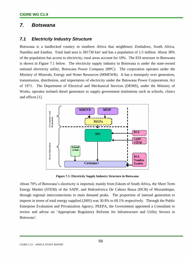
CIGRE WG C1.9
CIGRE C1.9 – AFRICA STUDY REPORT
59
7. Botswana
7.1 Electricity Industry Structure
Botswana is a landlocked country in southern Africa that neighbours Zimbabwe, South Africa,
Namibia and Zambia. Total land area is 581730 km² and has a population of 1.5 million. About 38%
of the population has access to electricity; rural areas account for 18%. The ESI structure in Botswana
is shown in Figure 7.1 below. The electricity supply industry in Botswana is under the state-owned
national electricity utility, Botswana Power Company (BPC). The corporation operates under the
Ministry of Minerals, Energy and Water Resources (MMEWR). It has a monopoly over generation,
transmission, distribution, and importation of electricity under the Botswana Power Corporations Act
of 1971. The Department of Electrical and Mechanical Services (DEMS), under the Ministry of
Works, operates isolated diesel generators to supply government institutions such as schools, clinics
and offices [1].
Figure 7.1: Electricity Supply Industry Structure in Botswana
About 70% of Botswana’s electricity is imported, mainly from Eskom of South Africa, the Short Term
Energy Market (STEM) of the SAPP, and Hidroelctrica De Cahora Bassa (HCB) of Mozambique,
through regional interconnections to meet demand peaks. The proportion of internal generation to
imports in terms of total energy supplied (2005) was 30.9% to 69.1% respectively. Through the Public
Enterprise Evaluation and Privatization Agency, PEEPA, the Government appointed a Consultant to
review and advise on ‘Appropriate Regulatory Reforms for Infrastructure and Utility Sectors in
Botswana’.
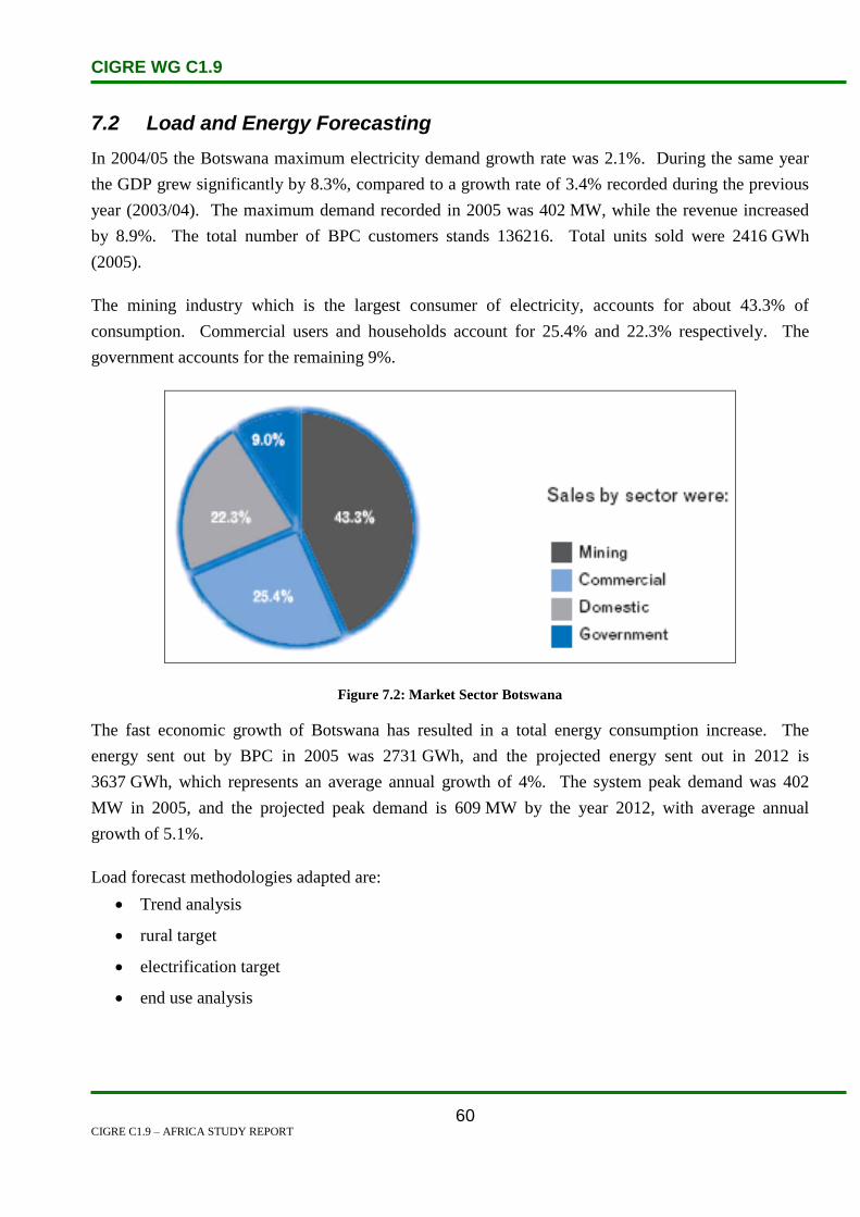
CIGRE WG C1.9
CIGRE C1.9 – AFRICA STUDY REPORT
60
7.2 Load and Energy Forecasting
In 2004/05 the Botswana maximum electricity demand growth rate was 2.1%. During the same year
the GDP grew significantly by 8.3%, compared to a growth rate of 3.4% recorded during the previous
year (2003/04). The maximum demand recorded in 2005 was 402 MW, while the revenue increased
by 8.9%. The total number of BPC customers stands 136216. Total units sold were 2416 GWh
(2005).
The mining industry which is the largest consumer of electricity, accounts for about 43.3% of
consumption. Commercial users and households account for 25.4% and 22.3% respectively. The
government accounts for the remaining 9%.
Figure 7.2: Market Sector Botswana
The fast economic growth of Botswana has resulted in a total energy consumption increase. The
energy sent out by BPC in 2005 was 2731 GWh, and the projected energy sent out in 2012 is
3637 GWh, which represents an average annual growth of 4%. The system peak demand was 402
MW in 2005, and the projected peak demand is 609 MW by the year 2012, with average annual
growth of 5.1%.
Load forecast methodologies adapted are:
Trend analysis
rural target
electrification target
end use analysis

CIGRE WG C1.9
CIGRE C1.9 – AFRICA STUDY REPORT
61
Annual Energy sent out
01000200030004000
1995 2000 2005 2010 2015
Year
GW
h
Annual Energy sent out
Figure 7.3: Annual Energy Sent Out in Botswana
7.3 Planning and Design Criteria
5.3.1 Generation criteria adopted by Botswana include:
Probabilistic
reserve margin greater than 15%
fuel mix policy
5.3.2 Transmission criteria include:
N-1 criterion is used
distribution voltage (±5%)
frequency (±0.5 Hz)
5.3.3 BPC owns and operates the Morupule Power Station, a coal-fired and dry-cooled power plant
with an installed capacity of 132 MW (4x33 MW units). BPC operates a significant network of
transmission and distribution lines to transport electricity from the power station or point of
import to consumers.

CIGRE WG C1.9
CIGRE C1.9 – AFRICA STUDY REPORT
62
7.4 Planning Approaches and Methods
The government has adopted an Integrated Energy Planning (IEP) process in order to meet the basic
energy requirements of the economy. Table 6.1 gives a summary of key projects. The fast economic
growth of the country has caused substantially high energy consumption, thus underlying the need for
the expansion of energy supply. Also, in view of the backdrop that surplus power for the SADC
region is projected to run out in the years 2007–2010, the Botswana Power Corporation is
implementing a project for the expansion of generation capacity at the Morupule Power Station.
Implementation of this project is expected to start during 2006/2007 and is planned to be completed in
2009/2010. The project will increase generation capacity by 300%, from 132 MW to 532 MW.
Efforts are continuing to increase the power supply in the region, and one such initiative is the
development of a power corridor by the establishment of Westcor, a company owned by the electricity
utilities of Angola, Botswana, the Democratic Republic of Congo, Namibia and South Africa. This
project has however encountered difficulties in 2009, with the withdrawal of the Democratic Republic
of Congo. South Africa is also looking at supporting Botswana for new power station projects like
Mmamabula Coal Fired power station.
Table 7.1: Short and Long Term Generation Projects
Short Term Generation Project
Project Capacity Type Expected Year
Morupule
Expansion
240 MW Coal 2009
Long Term Generation Project
Mmamabula 3 600 MW Thermal 2015

CIGRE WG C1.9
CIGRE C1.9 – AFRICA STUDY REPORT
63
Figure 7.4: Botswana Power Network
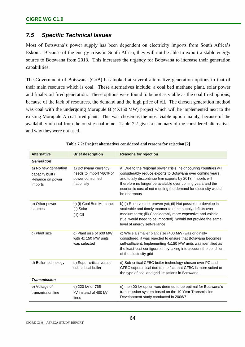
CIGRE WG C1.9
CIGRE C1.9 – AFRICA STUDY REPORT
64
7.5 Specific Technical Issues
Most of Botswana’s power supply has been dependent on electricity imports from South Africa’s
Eskom. Because of the energy crisis in South Africa, they will not be able to export a stable energy
source to Botswana from 2013. This increases the urgency for Botswana to increase their generation
capabilities.
The Government of Botswana (GoB) has looked at several alternative generation options to that of
their main resource which is coal. These alternatives include: a coal bed methane plant, solar power
and finally oil fired generation. These options were found to be not as viable as the coal fired options,
because of the lack of resources, the demand and the high price of oil. The chosen generation method
was coal with the undergoing Morupule B (4X150 MW) project which will be implemented next to the
existing Morupule A coal fired plant. This was chosen as the most viable option mainly, because of the
availability of coal from the on-site coal mine. Table 7.2 gives a summary of the considered alternatives
and why they were not used.
Table 7.2: Project alternatives considered and reasons for rejection [2]
Alternative Brief description Reasons for rejection
Generation
a) No new generation
capacity built /
Reliance on power
imports
a) Botswana currently
needs to import >80% of
power consumed
nationally
a) Due to the regional power crisis, neighbouring countries will
considerably reduce exports to Botswana over coming years
and totally discontinue firm exports by 2013. Imports will
therefore no longer be available over coming years and the
economic cost of not meeting the demand for electricity would
be enormous
b) Other power
sources
b) (i) Coal Bed Methane;
(ii) Solar
(iii) Oil
b) (i) Reserves not proven yet; (ii) Not possible to develop in
scaleable and timely manner to meet supply deficits over
medium term; (iii) Considerably more expensive and volatile
(fuel would need to be imported). Would not provide the same
level of energy self-reliance
c) Plant size c) Plant size of 600 MW
with 4x 150 MW units
was selected
c) While a smaller plant size (400 MW) was originally
considered, it was rejected to ensure that Botswana becomes
self-sufficient. Implementing 4x150 MW units was identified as
the least-cost configuration by taking into account the condition
of the electricity grid
d) Boiler technology d) Super-critical versus
sub-critical boiler
d) Sub-critical CFBC boiler technology chosen over PC and
CFBC supercritical due to the fact that CFBC is more suited to
the type of coal and grid limitations in Botswana.
Transmission
e) Voltage of
transmission line
e) 220 kV or 765
kV instead of 400 kV
lines
e) the 400 kV option was deemed to be optimal for Botswana’s
transmission system based on the 10 Year Transmission
Development study conducted in 2006/7

CIGRE WG C1.9
CIGRE C1.9 – AFRICA STUDY REPORT
65
7.6 Financing Issues
The Morupule B project’s transmission lines and substations will be funded by the African
Development Bank with assistance from the World Bank. The GoB will be the borrower of the loan
while the BPC (which is 100% owned by the GoB) will be the beneficiary.
Table 7.3: Base Case financial and economic returns [2]
Item Base case returns
FIRR / FNPV @ 5.0% real (Base case) 6.7% / Pula 2.3 billion (USD 328 million)
EIRR / ENPV @ 12.0% real (Base case) 24.9% / Pula 11.9 billion (USD 1.7 billion)
Table 5.3 shows results of the financial and economic analyses for the Morupule B project. These
figures show that the project is feasible and supports its implementation. The estimated financial
internal rate of return (FIRR) is higher than BPC’s estimated Weighted Average Cost of Capital
(WACC) of 5.0% and the
Base Case Economic internal rate of return (EIRR) is estimated at is also higher than the assumed
Economic Opportunity Cost of Capital (EOCK) in Botswana of 12.0% [2].
7.7 Human Resources
The BPC will be responsible for the expansion of the Botswana power generation effort. They will
appoint an external project manager to oversee the overall project. They will use their own resources
as well as external and internal contractors for various tasks, such as:
Safeguards will dealt with by an internally formed for implementation, planning and
enforcement. A Chief Safeguard Officer and a Environmental Liaison Officer will be appointed to
oversee this task
The design and tender documents for the transmission lines and substations will be compiled by the
following internal consultants:
o Merz and McLellan (Botswana)
o TAP/KEC Consortium
o PB Power
A consultant will also be recruited to oversee the construction of the transmission lines and
substations.
The construction of the power plant will be supervised by Fitchner while a design engineer will
be appointed for the water development system.
A inter-ministerial Steering Committee will also be established

CIGRE WG C1.9
CIGRE C1.9 – AFRICA STUDY REPORT
66
7.8 References
1. http://unfccc.int/ttclear/pdf/Workshops/Bonn/Botswana.pdf
2. http://www.afdb.org/fileadmin/uploads/afdb/Documents/Project-and-
Operations/Botswana%20-%20The%20Morupule%20B%20Power%20Project.pdf

CIGRE WG C1.9
CIGRE C1.9 – AFRICA STUDY REPORT
67
8. Burkina Faso
8.1 Electricity Industry Structure
Burkina Faso is situated in the heart of West Africa as shown in Figure 8.1. This is a country of plains
covering 274 000 km2 between Mali and Niger in the north and Côte d’Ivoire, Ghana, Togo and Benin
in the south. It has an estimated population of 13.3 million; with a rather low average density of 49
persons per km2. The country’s economy is still dominated by primary activities, which account for
nearly 90% of its exports. Cotton (65%) and animal rearing are predominant. However, the
contribution of the primary sector (approximately 39%) to the gross domestic product is surpassed by
the tertiary sector which accounts for 44% of the total [3].
Figure 8.1: Geographic Map of Burkina Faso
Since 1998 Burkina Faso has embarked on institutional, legal and regulatory reforms of its electricity
sector, in order to create enabling conditions for private sector participation [2].
The following is a summary of powers and scope of intervention of the different stakeholders in the
Burkina Faso power sector, as illustrated in Table 8.1.
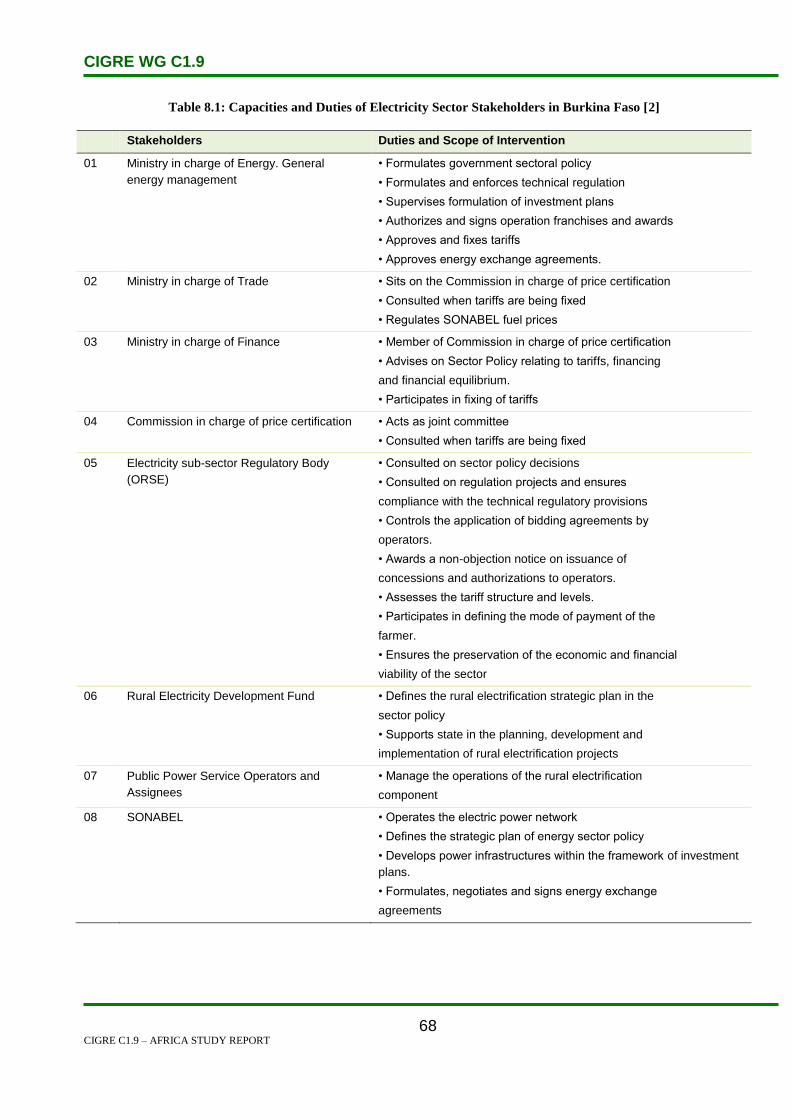
CIGRE WG C1.9
CIGRE C1.9 – AFRICA STUDY REPORT
68
Table 8.1: Capacities and Duties of Electricity Sector Stakeholders in Burkina Faso [2]
Stakeholders Duties and Scope of Intervention
01 Ministry in charge of Energy. General
energy management
• Formulates government sectoral policy
• Formulates and enforces technical regulation
• Supervises formulation of investment plans
• Authorizes and signs operation franchises and awards
• Approves and fixes tariffs
• Approves energy exchange agreements.
02 Ministry in charge of Trade • Sits on the Commission in charge of price certification
• Consulted when tariffs are being fixed
• Regulates SONABEL fuel prices
03 Ministry in charge of Finance • Member of Commission in charge of price certification
• Advises on Sector Policy relating to tariffs, financing
and financial equilibrium.
• Participates in fixing of tariffs
04 Commission in charge of price certification • Acts as joint committee
• Consulted when tariffs are being fixed
05 Electricity sub-sector Regulatory Body
(ORSE)
• Consulted on sector policy decisions
• Consulted on regulation projects and ensures
compliance with the technical regulatory provisions
• Controls the application of bidding agreements by
operators.
• Awards a non-objection notice on issuance of
concessions and authorizations to operators.
• Assesses the tariff structure and levels.
• Participates in defining the mode of payment of the
farmer.
• Ensures the preservation of the economic and financial
viability of the sector
06 Rural Electricity Development Fund • Defines the rural electrification strategic plan in the
sector policy
• Supports state in the planning, development and
implementation of rural electrification projects
07 Public Power Service Operators and
Assignees
• Manage the operations of the rural electrification
component
08 SONABEL • Operates the electric power network
• Defines the strategic plan of energy sector policy
• Develops power infrastructures within the framework of investment
plans.
• Formulates, negotiates and signs energy exchange
agreements

CIGRE WG C1.9
CIGRE C1.9 – AFRICA STUDY REPORT
69
Société Nationale d’Electricité du Burkina Faso, known as SONABEL, is the sole electricity supply
utility. SONABEL’s generation facilities are almost exclusively thermal and are located in the capital
Ouagadougou and several other urban areas. Overall generation capacity in Burkina Faso is believed
to be 78 MW, with 70% of this supplied by thermal power stations. There is no national transmission
network and the distribution network is limited. Only 7% of the country has access to electricity and
electricity is expensive. Growing demands for power have prompted Burkina Faso to seek to import
electricity from neighbouring Côte d’Ivoire. A power line connecting the city of Ferkessedougou in
northern Côte d’Ivoire with Ouagadougou, began operation in 2005. Burkina Faso uses diesel
generators to produce electricity, but high production costs prompted the government to begin
interconnecting its grid with those of Ghana and Côte d’Ivoire to import the additional electricity
requirements [1].
Transmission
SONABEL’s power system comprises two sub-systems known as regional consumption centres which
are interconnected in as shown in Figure 8.2. In addition to these systems, are the Isolated Networks
(IN). The power system is organized as follows:
The interconnected network of the Regional Centre for Consumption at Ouagadougou (CRCO)
consists of Ouaga I, Ouaga II, Koudougou and Kossodo thermal stations, as well as Kompienga
and Bagré hydropower stations. This network principally supplies Ouagadougou and its
environs, Kompienga and Koudougou.
The interconnected network of the Regional Centre for Consumption at Bobo-Dioulasso
(CRCB) consisting of Bobo I and Bobo II thermal stations, Tourni and Nioila hydro stations as
well as the 225 kV interconnecting line with Côte d’Ivoire. This network supplies Bobo-
Dioulasso and its environs as well as the south-west regions of the country.
The so-called Isolated Networks (IN) consist of a set of diesel units supplying the different
communities in the country and the two centres of Léo and Pô receive supplies through
connection to the Ghanaian network [2].

CIGRE WG C1.9
CIGRE C1.9 – AFRICA STUDY REPORT
70
Figure 8.2: Burkina Faso Transmission Network
High Voltage Transmission Network
SONABEL’s High Voltage (HV) Transmission Network comprises of three voltage levels arranged as
follows:
The 225 kV interconnection line from Ferkéssoudougou (Côte d’Ivoire) to Bobo-Dioulasso
(Burkina Faso) covering a length of 225 km, with an extension to Ouagadougou planned for
end of 2008.
The 132 kV interconnection lines connecting Bagré and Kompienga hydro power stations to
Patte d’Oie substation in Ouagadougou via Zano substation, 315 km in length.
The 90 kV lines linking on the one hand the Koudougou thermal power station to the Patte
d’Oie substation and, on the other hand, Ouaga I&II and Kossodo thermal power stations to
Zagtouli substation. The 90 kV network covers a total length of 126 km, of which 97.5 km
(Koudougou – Zagtouli – Patte d’Oie) is operated at 33 kV [2].

CIGRE WG C1.9
CIGRE C1.9 – AFRICA STUDY REPORT
71
Distribution Network
The Medium Voltage (MV) distribution network comprises the following voltage levels:
15 kV, 20 kV and 33 kV. The total length of the MV networks was 1 623 km in 2005, compared with
1 504 km in 2004.
The length of the Low Voltage (LV) network was 4 891 km in 2005 and 4 660 km in 2004, i.e. an
increase of 231 km. The increase was due to the achievement of 22 745 new connections [2].
8.2 Load and Energy Forecasting
Table 8.2 shows the demand forecast for Burkina Faso to 2020. In recent years, national consumption
has increased at an annual rate of slightly more than 7%, which is faster than the GDP growth
(elasticity of around 1.5). The national rate of electrification and the town of Ouagadougou alone
represents more than 90% of CRCO’s consumption.
The residential sector largely dominates, followed by the tertiary sector. Peak demand in 2003 was
105.2 MW, which is forecast to reach 282 MW by 2020 (average 6.3% growth per year) [3].
Table 8.2: Demand Forecast for Peak Power and Energy for Burkina Faso [3]
2003 2007 2011 2015 2020
Peak Power (MW)
CRCO 83 104 139 175 220
CRCB 22 31 39 48 62
Total 105 135 178 223 282
Energy (GWh)
CRCO 338 480 646 810 1019
CRCB 115 145 179 220 286
Total 453 625 825 1030 1305
The sales realized from 775 medium voltage (MV) customers accounted for 198.468 GWh as against
168.991 GWh in 2004 for 738 customers of the same category, thus representing an increase in sales
by 17.4%. The 255 738 low voltage (LV) customers consumed 338.995 GWh in 200 while 305.698
GWh was consumed by 234 122 LV customers in 2004, i.e. an increase in sales by 10.89%, as
illustrated in Table 8.3.
Table 8.3 presents some information on sales and customer growth. Between 2004 and 2005, the
number of SONABEL’s customers grew by 9.2% and the sales rose by 13.7%. Sales generated from
low voltage customers accounted for 63.1% of the total sales while medium voltage customers
accounted for 36.9%, i.e. a slight increase by 1.6% compared to the 35.3% generated in 2004. The

CIGRE WG C1.9
CIGRE C1.9 – AFRICA STUDY REPORT
72
number of new connections achieved stood at 22 745 in 2005, as against 23 202 in 2004, i.e. a decrease
of 1.97% [3].
Table 8.3: Evaluation of SONABEL Power Sales and Number of Customers by Category [2]
2004 2005 Evaluation
Number
of
customer
Sales in
GWh
Share
(%)
Number of
customers
Sales in
GWh
Share
(%)
Customer
Increase
Sales
Increase
Low voltage 234 122 305 698 64.7 255 738 338 995 63.1 9.22% 10.89%
Medium
voltage
738 168 991 35.3 755 198 468 36.9 2.30% 18.85%
SONABEL 234 860 472 690 100 256 493 537 463 100 9.21% 13.70%
8.3 Planning and Design Criteria
The Burkina Faso electricity supply network consists of two sub-systems, which were planned to be
inter-connected by 2005 [1]. These were:
The Regional Centre for Consumption at Bobo-Dioulasso (CRCB), which, in addition to the
country’s second city, includes other population centres in the southwest, including Banfora.
Until August 2000, this system was supplied by diesel generators, supplemented by two small
hydro power stations at Niofila and Tournir. Since August 2000, the CRCB has been connected
to the Côte d’Ivoire grid through a 225 kV line between Bobo and Ferkessedoughou.
The Regional Centre for Consumption at Ouagadougou (CRCO) which includes the capital,
Ouagadougou and other cities such as Koudougou (third largest city in the country), Ziniare and
Tenkodogo. The CRCO receives its power from four thermal power stations. These are the
three power stations of Ouagadougou (Ouga 1, Ouga 2 and Kossodo), which total
approximately 80 MW installed capacity for an estimated usable power of 67 MW at best, and
Koudougou power station with an installed capacity of 5.7 MW. This system is also fed by two
hydropower stations, at Kompienya and Bagre, situated in the south east of the country. The
latter two have a guaranteed output of 18 MW, approximately one-third of the power consumed
by CRCO [3].
As a general rule, the quality of service of SONABEL transmission and distribution network
deteriorated in 2005 as against 2004, which again was better than 2003. This decline is attributable to
the rise in inadvertent disruptions, service incidents or load shedding that increased from 1 411 points
in 2004 to 1 482 points in 2005, i.e. a 5.03% rise for both systems (CRCO and CRCB). The mean
outage time (MOT) remained constant at 38.4 minutes for CRCO between 2004 and 2005.

CIGRE WG C1.9
CIGRE C1.9 – AFRICA STUDY REPORT
73
Conversely, it dropped for CRCB from 36.1 minutes in 2004 to 32.3 minutes in 2005, i.e. an
improvement of about 4 minutes.
Un-served energy for its part, increased sharply within the sub-systems. For CRCO, it rose from 1.6
GWh in 2004 to 2.454 GWh in 2005. It was mainly due to insufficiency in generation capacity caused
by the delay in the commissioning of new capacity at the Kossodo plant. For CRCB, the un-served
energy increased from 0.212 GWh in 2004 to 0.427 GWh in 2005, i.e. a rise of 101%. One of the
causes of this deterioration was the three-week unavailability of the Côte d’Ivoire interconnection line.
The losses recorded on SONABEL’s distribution network were in the order of 12.61% in 2005
compared with 13.53% in 2004. This slight improvement in performance was due to the loss reduction
oriented policy initiated by SONABEL, notably the war against fraud which is essentially responsible
for the losses incurred. Though the global losses decreased slightly in 2005 vis-à-vis 2004, they are
still very high, requiring on-going strong measures to support the trend [2].
The findings of the report for ‘Project de renforcement des capacities de planification de la SONABLE
par l’etude du schema directeur du systeme regional d’approvisionment en electricite de
Ouagadougou’ identified the following problems encountered in both the structure and the working of
CRCO distribution systems [3]:
Overloading of certain distribution transformers.
Overloading of certain 15 kV outgoing lines.
Unacceptable voltage drop on 15 kV connections.
Lack of selectivity and problems of protection.
8.4 Planning Approaches and Methods
Ouagadougou Master Plan prepared by the group of consultants Dansk Energy Management-
Tractebel-CRC SOGEMA suggested the following projects [3]:
The 225 kV Bobo Dioulasso-Ouagadougou line in Burkina Faso to supply power from Côte
d’Ivoire to Ouagadougou via a new 225 kV single circuit line. The project was completed in
2006.
A 225 kV connection to the Ghana grid, ending at the Patte d’Oie substation, to be
commissioned in 2011, supplying contractual power limited to 20 MW.
Installation of ‘combined cycle’ thermal generation units between 2012 and 2020 with a total
capacity of 150 MW, supplemented at the end of the period by a 30 MW gas turbine for use at
peak periods.
Auaga 3 diesel generator power station, which would constitute the first independent electricity
CIGRE WG C1.9
CIGRE C1.9 – AFRICA STUDY REPORT
74
production unit in Burkina Faso, made possible by the liberalization of the electricity industry.
The project consists of three diesel generator units of 3 x 10 MW supplied with fuel oil,
possibly followed by a second phase of 2 x 10 MW units.
8.5 Specific Technical Issues
Burkina Faso’s electricity sector is currently faced with two problems:
(a) The need to ensure a substantial increase in the country’s power supply to meet a fast-
growing demand, and
(b) The need to extend power supply to several urban and rural localities, at the same time
improving the reliability and quality of the overall service.
In terms of reliance, Burkina Faso is highly dependent on imported hydrocarbons due to the fact that it
neither produces nor exports oil. Daily consumption is increasing. Figures indicate that from 8 000
barrels/day in 2000 to an increased 8 300 barrels/day in 2008. Growing demands for power have
prompted Burkina Faso to seek importation of electricity from the neighbouring Ivory Coast and
Ghana. In terms of the extended network, the national electricity access rate of 17% in 2008 is low. It
is only 4% in rural areas, owing to the limited transport and distribution networks in those areas.
Currently, 1 000 km of 33 kV lines, and another 400 km of low voltage lines have been refurbished in
the country, through the involvement of the African Development Bank. [4]
With regard to Burkino Faso’s capacity concerns, the current level of imports is a worrying factor on
national consumption. For example, in 2006, hydrocarbon imports totalled 340 500 tonnes, which is
1.04 times national consumption. The imports, representing 10 to 20% of all of the country’s gross
imports over the past 10 years, are increasing rapidly in the face of mounting demand to meet socio-
economic needs. [4]
The average production cost per kWh for 2008 was about 0.32 per kWh (US Dollar). Electricity
demand has been growing at a rate of 4.4% annually since 2003, when the final consumption was 35
kWh per inhabitant. The analysis of energy supply and demand balances for Burkina Faso indicates
that the system’s peak demand will reach 426 MW in 2020 from 131 MW in 2009. In terms of
renewable energy, the western location of Burkina Faso limits the potential for wind power. The
average wind speed ranges between 1 and 3 m/s, with the maximum only to be obtained in the North.
However, small-scale generators at suitable sites and for selective purposes (e.g. water pumping,
desalination systems, etc.) may be feasible. [4]
Traditional biomass fuels are used for meeting household energy needs but the potential for efficiency
in the residential sector has been identified. The introduction of energy-efficient stoves has proven a

CIGRE WG C1.9
CIGRE C1.9 – AFRICA STUDY REPORT
75
winner in reducing biomass demand, a project run by German Technical Assistance (GTZ) and Foyers
Améliorés au Burkina Faso (FAFASO). Energy efficiency projects have been run in the beer brewing
sector, financed by the Global Environmental Facility (GEF). [4]
8.6 Financing Issues
SONABEL is the main integrated operator, with a national monopoly on the generation and
distribution of electricity in the country’s urban centres. SONABEL is a public utility for which the
state provides the majority of operating capital. In March 2010, the government announced that the
previously proposed privatization of SONABEL was to be scrapped, due to the belief within the
government that a privately managed, performance-contracted organization is more effective than full
privatization.
The limited fossil energy sources available in Burkina Faso are not utilized commercially. Energy is
provided by fuelwood (main source), proceeded by hydrocarbons, hydroelectricity and renewables,
solar being the most commonly used. The constraints on the utilization of hydropower have led the
country to set up thermal power generation plants with high production costs to meet a fast growing
demand. [4]
Burkina Faso are currently benefiting from the results of a new and improved energy infrastructure.
They received a $38 million loan from the African Development Bank (AfDB) to improve access to
electricity for nearly 800 000 people. The AfDB loan will fund the Electricity Infrastructure
Strengthening and Rural Electrification Project. The AfDB acknowledged that demand for electricity
in the country is growing at a fast rate annually and at the same time struggling to develop new energy
sources. With the help of the AfDB and an agreement known as the West African Power Pool, the
country’s electrical grid will be connected to the grids of its neighbours Ghana and Côte d’Ivoire.
Those two countries, which border the sea and have easier access to sources of electricity, will be the
main conduits for the increased supply of power in Burkina Faso. Once the project is completed,
access to electricity should become much more consistent for the population. Currently, the Burkinabe
people find energy from a varied supply of sources, many of which are more expensive than electric
provided on a grid system. Increased energy provisions will also help the government make progress in
achieving globally recognized development needs, including access to water and health care. AfDB
claims that once the Burkina Faso grid is connected, economic activity will increase and encourage
more business development. [6]
8.7 Human Resources
SONABEL is doing its own generation, transmission and distribution planning. However, external
consultants do carry out some work affecting the network expansion. The following are examples of

CIGRE WG C1.9
CIGRE C1.9 – AFRICA STUDY REPORT
76
work carried out by external consultants.
Nexant for planning studies for the use of USAID and ECOWAS [3]. The purpose of the
Regional Transmission Study evaluates the new cross-border transmission projects that are
proposed for the West Africa interconnected power system over the 2004 to 2020 planning
horizon. This is for the benefit of ECOWAS member countries, USAID, lenders and other
donors [3].
The report which was prepared in 2000 by the group of consultants Dansk Energy
Management-Tractebel-CRC SOGEMA with the title: ‘Project de renforcement des capacities
de planification de la SONABLE par l’etude du schema directeur du systeme regional
d’approvisionment en electricite de Ouagadougou’. The purpose of the studies was to enhance
the planned capacity of SONABEL to supply Ouagadougou with electricity [3].
Another report, titled: ‘Rapport Final Volume 4 – Comparaison des alternatives (SOGREAH,
June 2002)’, studies the optimal generation and transmission investments to meet the demand at
least cost and under acceptable conditions of supply reliability and quality. The purpose of this
study was to provide an economic comparison of the various alternatives put forward and
defined in the previous studies. The studies were performed by consultants Dansk Energy
Management-Tractebel-CRC SOGEMA [3].
8.8 References
1. http://www.mbendi.com/indy/powr/af/bf/p0005.htm
2. http://www.ecowapp.org/WAPP%20PDFS/KPI-ENG.pdf
3. ‘West Africa Regional Transmission Study’. Volume 2: Master Plan
4. http://www.reeep.org/index.php?id=9353&special=viewitem&cid=122
5. http://www.state.gov/r/pa/ei/bgn/2834.htm
6. http://allafrica.com/stories/201002120900.html
CIGRE WG C1.9
CIGRE C1.9 – AFRICA STUDY REPORT
77
9. Burundi
9.1 Electricity Industry Structure
Burundi is small landlocked country in the Great Lakes region of eastern central Africa, sharing
borders with Rwanda 290 km, Tanzania 451 km and Democratic Republic of Congo (DRC) 233 km.
Burundi’s population was in the order of 7 000 000 in 2002.
There are two organizations involved in the generation and supply of electricity in Burundi:
Société Internationale des Pays des Grands Lacs (Sinelac), was established by Burundi, Rwanda
and Democratic Republic of Congo, to develop international electricity projects.
Régié de Production et Distribution d’Eau et d’Electricité (Regideso), is a state-owned
vertically integrated utility. REGIDESO operates Burundi’s thermal power stations located in
Bujumbura and the surrounding areas, and a small amount of hydro capacity in rural areas. It
also operates the transmission system and the distribution network in Burundi, purchasing
electricity from the Sinelac site at Rusizi via a 110 kV transmission line operated by
Democratic Republic of Congo.
The Ministre de l’Énergie et des Mines exerts main regulatory powers over the power and water
sectors.
Direction Générale de l’Hydraulique et des Énergies Rurales (DGHER) is mandated to carry out water
supply and electrification projects in rural areas.
Between 50% and 60% of the electricity consumed comes from the Ruzizi I and II power stations,
which belong jointly to Burundi, Rwanda and Democratic Republic of Congo.
9.2 Load and Energy Forecasting
Burundi employs the following load forecast methodologies:
Historical trend.
Rural target.
Electrification target.
Top-down approach.

CIGRE WG C1.9
CIGRE C1.9 – AFRICA STUDY REPORT
78
When forecasting the electricity demand of Burundi in terms of economic indicators and population
(i.e. combinations of variables such as the sectoral GDP and/or population), it was found that the
variables that should be retained in order to have most reasonable and consistent results are the GDP of
the primary and tertiary sectors, and the population.
Table 9.1: GDP Growth Rate (2002~2020) in Burundi
The other elements affecting the load forecast are the removal of constraints on demand, the inclusion
of an allowance for rural electrification and the reduction of technical losses. The forecasted GDP
growth rates are shown in Table 9.1 The assumptions used for in load forecasting, as well as the load
factor, are illustrated in Table 9.2.
Table 9.2: Assumptions Made for Load Forecast Preparation in Burundi
The forecast energy and peak demand requirements for Burundi are illustrated in Figure 9.1 and Figure
9.2 respectively. The energy requirements are at the ‘energy sent out’ level which includes sales and
losses. Auxiliary consumption at the power plants is not included and would need to be added if gross
production were required. The demand figure is the maximum demand on the system (corresponding

CIGRE WG C1.9
CIGRE C1.9 – AFRICA STUDY REPORT
79
to sales plus losses) as well as an allowance for a reserve margin of 20%.
Figure 9.1: Peak Power Demand in Burundi
Source SSEA II – Regional Power Needs Assessment report
Figure 9.2: Energy Demand in Burundi
Source SSEA II – Regional Power Needs Assessment report

CIGRE WG C1.9
CIGRE C1.9 – AFRICA STUDY REPORT
80
9.3 Planning and Design Criteria
Burundi’s power production rose to 127.1 GWh in 2002 from 114.1 GWh in 2001. Most power was
generated from hydroelectric sources. In 2002 the consumption of electricity fell to 117.3 GWh from
122.2 GWh in 2001. Industrial consumption rose to 49.9 GWh from 42.1 GWh.
Burundi maintains a reserve margin of 15%.
9.4 Planning Approaches and Methods
Multi-Sectoral Water and Electricity Infrastructure Project (2008–2013)
The project is funded by The World Bank at a cost of $50 million. It supports the Government of
Burundi’s efforts to:
1. increase access to water supply services in peri-urban areas of Bujumbura
2. increase the reliability and quality of electricity services [1]
Interconnection of Electric Grids of Nile Equatorial Lakes Countries
The project consists of the construction and upgrading of 769 km of 220 kV and 110 kV power lines
and 17 transformer stations to interconnect the electric grids of the Nile Basin Initiative Member
countries (NBI), namely Burundi, DR Congo, Egypt, Ethiopia, Kenya, Rwanda, Sudan, Tanzania and
Uganda. [1]
OtherProjects
Feasibility is a major factor and would cost around 750 million dollars. When the resources are
available the following projects can commence. These include:
Kabu 16 (20 MW) and Mpanda (10.4 MW) and two regional projects : Rusizi III (145 MW to be
divided with Rwanda and the DRC) and Rusumo Falls (61 MW to be divided with Rwanda and
Tanzania) are two further hydro-electric projects. Burundi also plans another national project:
Jiji/Mulembwe/Siguvyaye in the south of Burundi rated for 100 MW or more, and on Ruvubu
(Mumwendo site: 80 MW). [1]
9.5 Specific Technical Issues
Burundi’s Poverty Reduction Strategy (2006) identifies the severe shortfall in electricity supply as a
major constraint for development. It recognizes the need to undertake urgent actions (including the
rehabilitation of existing power plants and the construction of new facilities) to ensure an adequate

CIGRE WG C1.9
CIGRE C1.9 – AFRICA STUDY REPORT
81
power supply, and endorses the government’s plan to undertake a rural electrification programme by
extending the grid and connecting villages, as well as disseminating information on alternative energy
sources which are affordable for low-income households.
Moreover, to promote solar energy use and to reduce the high cost of acquiring solar equipment, the
government plans the reduction or the suppression of the taxes which are applied to photovoltaic
panels. Nevertheless, solar systems have undergone a certain expansion due to diverse NGO initiatives
to cover especially deprived sectors. For example, since 2006, more than 95 community organizations
(centres of health, communal colleges and social centres) have been outfitted with solar photovoltaic
installations. [1]
Solar
Average solar insolation stands at 4–5 kWh/m2/day. Solar energy is being investigated and utilized as
a means of off-grid electrification for rural areas. Institutions such as the Solar Electric Light Fund
have also invested in small solar systems for public buildings, such as health centres. [1]
Wind
Data on wind patterns has been recorded by the Institute for Agronomic Sciences of Burundi (ISABU),
primarily for agricultural purposes, give a mean wind speed between 4 and 6 m/s. More potential sites
probably exist in the higher elevations. Pilot private-sector schemes are currently operational.
Biomass
Biogas is a form of energy adapted well to the needs for Burundi. The current government plan is to
produce energy by means of digesters. Fuel-wood accounts for the vast majority of Burundi’s energy
consumption. However, potential wood consumption in the country is forecast to require production of
180 000 hectares, which surpasses the current forest coverage of 174 000 hectares, suggesting the need
for reduction of consumption and re-forestation programmes.
Geothermal
Resources have been identified, but there is little available data to assess commercial viability, the last
geothermal study of the region having been conducted in 1968.
Hydropower
Burundi’s theoretical hydropower capacity is 1 700 MW, however, roughly 300 MW is seen as
economically viable, and only 32 MW has been exploited. [1]

CIGRE WG C1.9
CIGRE C1.9 – AFRICA STUDY REPORT
82
9.6 Financing Issues
Financing renewable energy requires major contributions, thus the country will inevitably struggle to
fund projects. [1]
The Burundian state promulgated, in August 2000, a law detailing the liberalization and regulation of
the public utility of drinking water and electric power, allowing the private sector to contribute to the
development of these sectors through Private Public Partnership (PPP). [1]
The state-owned company Regie de Production et de Distribution d’Eau et d’Electrcite (REGIDESO)
(the Water and Electricity Production and Distribution Authority) is in charge of production,
transmission and distribution in urban areas. It is a public utility company, placed under the
supervision of the Ministry of Energy and Mines. RIGIDESO mainly runs hydropower plants of high
capacity.[1]
Electricity is transmitted and distributed by REGIDESO, whilst the Société Internationale des Pays des
Grand Lacs (SINELAC), another state owned company responsible for development of indigenous and
joint power ventures with neighbouring countries, generates and sells power to REGIDESCO. [1]
9.7 Human Resources
The Burundian Centre for Studies of Alternative Energies was created in 1982 to conduct applied
research and disseminate knowledge of renewable energies, particularly solar, wind and biomass.
The Government and Ministry of Energy and Mines have formulated certain energy policies.
The responsibilities include:
to plan, control and coordinate all programmes and activities of the energy sector;
to promote exploration and exploitation of hydrocarbons while protecting the environment;
to enhance access to modern energy services at least cost; and
to elaborate laws and regulations for the best management of the sector
9.8 References
1. http://www.reeep.org/index.php?id=9353&text=policy&special=viewitem&cid=58

CIGRE WG C1.9
CIGRE C1.9 – AFRICA STUDY REPORT
83
10. Cameroon
10.1 Electricity Industry Structure
When the Cameroon government decided in June 1996 to privatize the electricity sector, it embarked
on a search for a strategic partner with adequate financial standing to help in improving and
modernizing the sector. Another objective was to significantly increase access of the population to
electricity and to transfer to Cameroonians, know-how that meets international standards. At the end
of five years of work devoted to the precise definition of the global restructuring strategy of the sector,
the American group AES-Corporation was chosen as a partner with the government in the Cameroon
Electricity Corporation. The government held, directly or indirectly, 97% of the share capital of the
Cameroon Electricity Corporation. On 18 July 2001, the state of Cameroon ceded 56% of the shares
of Sonel to the strategic partner, AES-Corporation. The new entity borne out of this transfer was
named AES-Sonel.
AES-Sonel is a semi-state company whose corporate purpose concerns all activities directly or
indirectly related to the generation, transmission and distribution of electrical energy in Cameroon. As
a subsidiary of AES-Corporation, it performs this mission within the framework of the concession
agreement and the electricity sales agreement, which define the related perimeter as well as the terms
and conditions.
AES-Sonel currently supplies less than 530 000 of Cameroon’s nearly 20 million people. AES-Sonel
is responsible for electricity generation, with the exclusive right to provide transmission and
distribution services in Cameroon.
Regulation of the electricity industry is performed by ARSEL. The overall role of ARSEL is to
regulate the electricity industry and ensure that consumers are provided with adequate and reliable
electricity supplies at prices that are affordable and reflect acceptable levels of efficiency.
Currently Cameroon has no independent power producers (IPPs) in place but with the regulatory and
institutional changes in the power sector in Cameroon, the country is ready for direct foreign
investments. The way is also open for IPPs and other energy investors, to enter Cameroon’s natural
gas sector and help secure the country’s energy needs for the rest of the century.
The Ministry for Energy and Water is placed under the authority of a Minister. It ensures the
supervision of the establishments and companies of production, transport, storage and distribution of
electricity, gas, oil and water, the Cameroonian company of oil terminals.
Cameroon focused on local skills development and attracted back locals living in Europe with good
experience. Access has been rising rapidly during the last few years.

CIGRE WG C1.9
CIGRE C1.9 – AFRICA STUDY REPORT
84
10.2 Load and Energy Forecasting
Cameroon’s energy demand in the electricity sector is as follows:
Installed production capacity = 855 MW
Effective production = 450 MW
This shortfall is due to a lack of efficient maintenance, the use of old facilities and equipment and the
influence of climatic conditions on hydro generation (harsh dry seasons). Steady growth has been
registered from industrialization, electrification and population growth.
Figure 10.1: Electricity production 2000-2011 [1]
Figure 10.2: Electricity consumption 2000-2011 [2]
Historic electricity consumption is illustrated in Table 10.1 below:
Table 10.1: Cameroon Historic Electricity Consumption
Year 1980 1985 1990 1995 2000 2001 2002

CIGRE WG C1.9
CIGRE C1.9 – AFRICA STUDY REPORT
85
Electricity Consumption
(GWh)
1452 2274 2731 2844 3378 3509 3304
Cameroon depends on hydropower for 95% of its energy supply. Only 5% of the country’s rural
population and 65% of urban dwellers currently have access to electricity. Demand for electricity
continues to grow at a rate of 8% per annum, and although the country’s sole power utility, AES-
Sonel, has increased energy output over the last five years, this continues to fall short of actual
demand.
10.3 Planning Approaches and Methods
Three inter-connected networks operate throughout the country, primarily powered by hydro stations
as illustrated in Table 10.2. Some diesel power stations produce electricity in remote locations and
during peak periods.
Table 10.2: Cameroon Installed Generation Capacity
Source Installed Capacity MW
Edea (Hydro) 263
Song-Loulou (Hydro) 384
Lagdo (Hydro) 72
Bassa (Thermal) 15
Mefou (Thermal) 9.5
Bafoussam (Thermal) 10
Small Plants 20
*Small Distributed Generation 82
Total 855.5
* AES-Sonel uses about forty generating units with a total installed capacity of 82 MW across the national territory. The
generating units are at present essentially used as back up plants in the Northern region.
Altogether there is 8 245 km of transmission network, including 2 365 km of HV network and
5 880 km of LV and MV network. The primary transmission in Cameroon is via 225 kV, 110 kV and
90 kV high voltage lines. The 225 kV network stretches for over 480 km in the south of the country.
The 110 kV network is situated in the north of the country and covers 337 km, of which 237 km are
operated temporarily as 90 kV. The 90 kV network has a total length of 1 547 km, which is split
between the south (1346 km) and the north (201 km). The low and medium voltage network supplies
households and businesses. The total length of this network is 5 880 km. The interconnection of the
network comprises 33 HV/MV transformer substations (30 in the south, 3 in the north) and
4 740 MV/LV substations.
The AES-Sonel distribution network is broken down into four electrical regions, namely:

CIGRE WG C1.9
CIGRE C1.9 – AFRICA STUDY REPORT
86
Littoral.
Centre.
West.
North.
On the southern interconnected grid, which comprises the first three electrical regions, 13 MV/HV
substations supply the distribution network. With regard to the northern grid, 4 substations play the
same role. About 30 isolated thermal power plants supply isolated areas with electricity.
Cameroon has a large hydro potential, only partially exploited. A possible total hydro capacity of
115 000 MW has been identified (World Resources Institute, 1996), but the installed hydro capacity
was only 719 MW in 1998. This potential is one of the most significant in African countries.
AES-Sonel and France’s Électricité de France (EDF) have conducted studies concerning a Chad-
Cameroon interconnector project.
AES-Sonel expects to add approximately 50 000 new electricity connections each year over the next
15 years. The company also plans to upgrade its existing transmission, distribution and generation
facilities.
10.4 Specific Technical Issues
AES-Sonel is the energy company authorized to supply electricity in Cameroon. This service is
provided mainly in urban areas. Those who have access to its services report low levels of satisfaction.
Problems raised include: frequent blackouts; low voltage; high bills; delays in billing; long waits at bill
payment counters; demand from AES-Sonel workers for extra sums of money from customers to
render services; inadequate explanation of AES-Sonel contracts with customers; and lack of
information on how to claim compensation for damages resulting from electricity service disruptions.
The government of Cameroon considers power shortages to be one of the key constraints to its
economic growth. The nation has an installed production capacity of 855 MW but the country's
effectively functioning productive capacity is, at present, only 450 MW. This shortfall is caused by
various factors including: reliance on aged facilities and equipment, the effect of harsh climatic
conditions, and a lack of long term maintenance. The performance of the power sector since 2001 has
been disappointing, as severe droughts have limited the supply of water, which is the source of 90% of
the electric power produced in Cameroon. To guard against outages in the dry season, Cameroon must
decrease its dependency on hydropower through diversification of its power generation capacity.

CIGRE WG C1.9
CIGRE C1.9 – AFRICA STUDY REPORT
87
10.5 Financing Issues
European Investment Bank (EIB) and AES-Sonel have signed a finance contract for €65 million to
part-finance AES-Sonel’s investment programme for rehabilitation and safety improvement of the
Song Loulou Dam and ancillary investments improving transmission and distribution of power. The
EIB, European Union’s long-term lending institution, supports AES-Sonel’s post-privatization
investment programme, which is estimated at €380 million and aims at boosting generation capacity
and improve electricity services. The project aims at raising the system’s efficiency, reliability and
quality and permits the extension to, on average, 50 000 annual additional connections over the next 15
years throughout Cameroon.
Government hopes to use the Lom Pangar dam to regulate seasonal flows of water into the Sanaga
River. With a planned capacity of 7.250 billion cubic meters in a reservoir that will cover 610 square
kilometers, the dam will be used to hold water back for release during dry the season to feed the Song-
Lou Lou and Edea dams on the Sanaga River downstream. The dam is expected to cost around $240
million, with funding coming from a consortium including the French Agency for Development, The
African Development Bank, IMF, and the Islamic Bank.
The AES Corporation announced that its subsidiary, AES-Sonel, plans to expand its electricity
network in Cameroon, more than doubling the number of people it currently serves over the next 15
years and extending its network to previously unsaved parts of the country. The improvements are part
of an amended concession agreement AES-Sonel has reached with the Government of Cameroon.
AES also announced that AES-Sonel secured a $340 million (€260 million) financing package – one of
the largest ever provided to a privatized utility in sub-Saharan Africa – to finance the majority of these
system improvements.
Because of its modest oil resources and favorable agricultural conditions, Cameroon has one of the
best-endowed primary commodity economies in sub-Saharan Africa. Still, it faces many of the serious
problems confronting other underdeveloped countries, such as stagnant per capita income, a relatively
inequitable distribution of income, a top-heavy civil service, endemic corruption, and a generally
unfavorable climate for business enterprise. Since 1990, the government has embarked on various IMF
and World Bank programs designed to spur business investment, increase efficiency in agriculture,
improve trade, and recapitalize the nation's banks. The IMF is pressing for more reforms, including
increased budget transparency, privatization, and poverty reduction programs. Subsidies for electricity,
food, and fuel have strained the budget. New mining projects - in diamonds, for example - have
attracted foreign investment, but large ventures will take time to develop. Cameroon's business
environment - one of the world's worst - is a deterrent to foreign investment [3].

CIGRE WG C1.9
CIGRE C1.9 – AFRICA STUDY REPORT
88
10.6 Human Resources
Of all school entrants, about 58% enter secondary school and 25 per cent overall reach the final grade
of secondary school The lack of money remains the leading cause of school dropout (up to 46% of
dropouts), and this clearly has a negative effect on the availability of skilled workers in the country.
Positive news update:
Cameroon focussed on local skills development and attracted back locals living in Europe with good
experience. Electrification and electricity access is now rising rapidly.
10.7 References
http://www.indexmundi.com/g/g.aspx?v=79&c=cm&l=en
http://www.indexmundi.com/g/g.aspx?v=81&c=cm&l=en
https://www.cia.gov/library/publications/the-world-factbook/geos/cm.html#top

CIGRE WG C1.9
CIGRE C1.9 – AFRICA STUDY REPORT
89
11. Cape Verde
Cape Verde has no indigenous sources of oil, natural gas, hydropower and coal. Total installed
electricity capacity(2010) was 116MW, 72% of which is derived from diesel fuel, 22% from
wind and 6 % is from solar energy. All petroleum products including gasoline, jet fuel and
kerosene have to be imported.
The energy balance of Cape Verde shows a high dependency on imported fossil fuels (11% of
total imports in 2009, costing US$ 78 million). Indigenous energy resources consist essentially
of biomass, as wind energy production is limited. Renewables in total contributed 2.7% to
primary energy in 2009, with the remainder being met by imported fuels. There are no
petroleum refineries on the islands, only storage facilities.
Energy usage by the different sectors are showen below.
Figure 11.1: Energy usage sectors (Source: GESTO 2011 and ELECTRA data)

CIGRE WG C1.9
CIGRE C1.9 – AFRICA STUDY REPORT
90
The electrification rate is 76%. The government has set a target of boosting this ratio to 90%
over the next few years. It also plans to generate 50% of electricity from renewable sources by
2020. In 2009, construction began on 5 wind farms which are expected to be finished this year.
In March 2010, the government secured funding of £26 mn from the British government for the
construction of 40 wind turbines capable of generating 40 MW of electricity. The Dutch
government is also providing financing for a wind-power project. In January, 2010, Martifer
Solar of Portugal signed a contract with the Ministry of Economic, Growth and
Competitiveness to build 2 photovoltaic solar energy facilities with a total capacity of 7.5 MW.
They will produce 4% of the electricity output and are expected to be completed by August.
The largest thereof was the Cabeolica wind farm project.
11.1 Electricity Industry Structure
Figure 11.2: Electricity production 2000-2011
GWh

CIGRE WG C1.9
CIGRE C1.9 – AFRICA STUDY REPORT
91
Figure 11.3: Electricity production 2000-2011
Extract from http://www.estandardsforum.org
Cape Verde has few natural resources, a limited water supply and is a net food importer.
The economy is dominated by the services sector with commerce, transport, tourism, and
public services accounting for about three-fourths of GDP. There is a large trade deficit
that is partially offset by foreign assistance and worker remittances. Cape Verde managed
to weather the global financial crisis and is primed for an acceleration in economic growth
as tourist receipts rebound and foreign direct investment inflows rise in response to the
government measures to encourage the development of casinos, hotels and resorts. The
government is also hoping to attract European investors to purchase property for second
and vacation homes
GWh
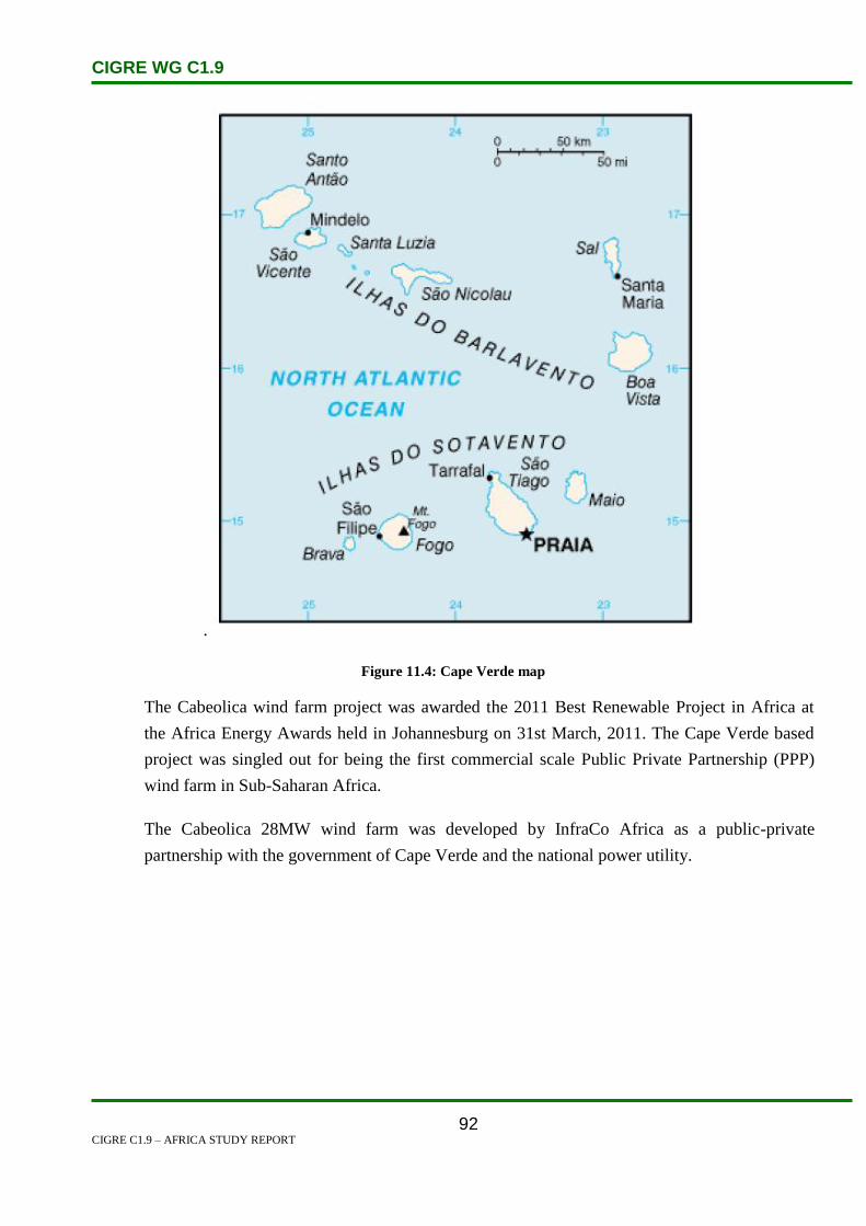
CIGRE WG C1.9
CIGRE C1.9 – AFRICA STUDY REPORT
92
.
Figure 11.4: Cape Verde map
The Cabeolica wind farm project was awarded the 2011 Best Renewable Project in Africa at
the Africa Energy Awards held in Johannesburg on 31st March, 2011. The Cape Verde based
project was singled out for being the first commercial scale Public Private Partnership (PPP)
wind farm in Sub-Saharan Africa.
The Cabeolica 28MW wind farm was developed by InfraCo Africa as a public-private
partnership with the government of Cape Verde and the national power utility.

CIGRE WG C1.9
CIGRE C1.9 – AFRICA STUDY REPORT
93
Figure 11.5: Cabeolica wind farm project
11.2 Load and Energy Forecasting
Electricity output has risen rapidly in recent years, climbing by 40.2% between 2009 to 2011.
11.3 Planning and Design Criteria
Further development for green energy is planned in Cape Verde. A development plan for four wind
farm sites in Santiago, S. Vicente, Sal and Boa Vista islands with nominal capacity of approximately
10MW; 6MW and 8MW, 4MW respectively, subject to an appraisal of the technical consultant, is
currently being studied
The African Development Fund, in co-operation with the Government of Cape Verde and the Japanese
International Cooperation Agency (JICA), aims to upgrade power distribution networks and improve
service quality for approximately 94% of the population, by targeting six islands in the group. Funding
for the project is primarily from the involved development agencies (98%). The project will extend the
existing medium- and low-voltage networks, rehabilitate transmission lines and substations, install the
SCADA system of control, defect identification and management equipment for three islands, and
replace faulty metering equipment. The practical benefits of these measures will include the
harmonisation of the involved islands’ electricity networks at 20 kV, the reduction of losses (both
commercial and technical), and the improvement of electricity access rate and quality.

CIGRE WG C1.9
CIGRE C1.9 – AFRICA STUDY REPORT
94
11.4 Planning Approaches and Methods
Solar energy
The potential for solar energy of Cape Verde is very high: 6 kWh/m²/day. Due to the high potential it
was intended that solar energy would cover 2 % of the total energy consumption by 2010, although
implementation of this target has been limited. There are several successful PV-based applications for
water pumping, lighting and telecommunication systems.
Solar Potential
Figure 11.6: Solar potential in Cape Verde

CIGRE WG C1.9
CIGRE C1.9 – AFRICA STUDY REPORT
95
Wind energy
According a study carried out by Helimax, Cape Verde is one of the 15 countries with the best wind
resource in Africa. The plentiful wind resource is confirmed by monitoring by the World Bank - an
average wind velocity of 7.5 m/s. At the end of 2004, there were 3 wind parks: in S. Vincent with an
installed capacity of 900 kWh, in Sal with 600 kWh, and in Santiago with 900 kWh, delivering 2.9%
of the electrical energy of the country. Recent developments have been made to the sector through
collaboration between the Africa Finance Corporation, the Finnish Fund for Industrial Cooperation and
Infraco, a consortium for African infrastructure development, in the Cabeólica project, operated by
Cabeólica S.A. The project consists of a total of 30 turbines, with 11 installed as of November 2011,
for a combined final output of 25.5 MW. Cabeólica S.A. will sell all power generated to ELECTRA
under a PPA.
Wind Potential
Figure 11.7: Wind potential in Cape Verde
The context seems favourable for wind energy to be competitive. There is also an interest in small
scale wind projects for small electrical grids in remote locations. Cape Verde is more favourable to
small and medium scale projects mainly because of the characteristics of the demand of electricity and
the electrical grid. However, the development of wind energy could be hampered because of

CIGRE WG C1.9
CIGRE C1.9 – AFRICA STUDY REPORT
96
restrictions on investment, and the need for further capacity building. Wind was also very popular in
the past for water pumping purposes.
Hydropower
There is almost no (economically feasible) potential for hydropower in the islands, predominantly due
to the limited water resources in the country. Wave power has been considered for the island nation,
with a Gesto study in 2011 indicating a potential of roughly 17 kW/m in some areas, mostly around the
islands of Sal and Santo Antão.
Figure 11.8: Hydropower potential in Cape Verde

CIGRE WG C1.9
CIGRE C1.9 – AFRICA STUDY REPORT
97
11.5 Specific Technical Issues
The national electricity grid is made of many non-interconnected grids. The small extension of each
network makes electricity generation more expensive, lowering efficiency and limiting the possibility
of balancing the power. Furthermore in Cape Verde the great number of power stations and the
presence in most islands of more than one network decreases the general efficiency of the system. The
electricity demands on each of the larger islands are typically in the range 10-20 MW. The electricity
demands have been constantly growing during recent years, and dramatic growth is expected in the
coming years, mainly due to planned developments of tourism on four of the islands – Santiago, São
Vicente, Sal and Boa Vista. A single power price is applied across all the islands despite cost
differences, on the grounds of social equity. In addition, the performance of ELECTRA as a utility has
previously been limited, with transmission and distribution losses reaching 26% in 2009, and a
traditionally low rate of cost recovery (71% in 2006). In addition, power outages are common across
the country, with approximately 1,337 hours without power service in the country in 2010.
To improve this situation in more recent years, ELECTRA has gradually switched off the oldest and
smallest power stations and has invested in electricity distribution infrastructures, in order to
rationalise consumption of fuels and production of electricity, and lower the costs involved. The
country, as of 2008, had one of the highest electricity tariff rates in Africa, with an average rate of US$
25 cents per kWh.
The energy utility Empresa de Electricidad e Agua (ELECTRA, www.electra.cv) was first
incorporated in 1998 (law no. 86/98), and, by the end of 1999, the state had sold 51% of its stocks for
€45.5 million to a Portuguese consortium under Portuguese government control. The state and
municipalities continued to hold 34% and 15%, respectively. The consortium committed to investing
€65 million, obtaining a 50-year concession. ELECTRA invested considerably at the beginning of their
mandate, but problems began to arise in relation to tariffs. At the end of 2001, the management
complained that the tariffs did not cover the rise in fuel costs.

CIGRE WG C1.9
CIGRE C1.9 – AFRICA STUDY REPORT
98
11.6 Financing Issues
Funded by the European Investment Bank and the African Development Bank at a cost of €60 million,
the project comprises of the development, construction and operation of four onshore wind farms,
including all interconnections from the wind farms to the local 20 kV grid connection points, and
associated transmission infrastructure on the islands of Santiago (9.65 MW), Boa Vista (4.25 MW),
Sal (7.65 MW) and Sao Vicente (5.95 MW) in Cape Verde. The wind farms will have a total installed
capacity of 27.2 MW. Construction initially began in winter 2011, and construction is hoped to be
complete by mid-2012.
As is the case in many other sub-Saharan African nations, China has been an active investor. The
Chinese government has provided financing for the construction of the national parliament building, a
stadium and two dams. Along with private Chinese investors, the Chinese government has also been
involved in funding projects in housing, energy, cement production and the restoration of Cabnave
shipyards.
The Cabeolica 28MW wind farm was developed by InfraCo Africa as a public-private partnership with
the government of Cape Verde and the national power utility. The US90 million project was financed
with equity from InfraCo Africa, Finnfund and the African Finance Corporation, and debt financing
provided by the European Investment Bank and the African Development Bank.
11.7 Human Resources
No discussion on human resources issues was presented.

CIGRE WG C1.9
CIGRE C1.9 – AFRICA STUDY REPORT
99
12. Central African Republic
The Central African Republic (CAR) is a landlocked country in central Africa with a tropical climate.
It borders Cameroon, Chad, the Republic of the Congo, Sudan and the Democratic Republic of the
Congo (DRC). The population is 4 511 488 and the population density is 7.2 people per sq. km.
Bangui is the capital, commercial center and the largest city. It has a population of 672 000. Arable
land accounts for 3.1% of the area of the country, 38.9% of the population lives in urban areas (UN
estimate for 2010), 36.5% of the country is covered by forests, 0.15% of the land area is devoted to
permanent crops and there are just 20 sq km of irrigated land. CAR is a former French colony and is
still influenced by France. CAR has rich unexploited natural resources consisting of diamonds, gold
uranium and other minerals. Diamonds are responsible for 40–55% of the national export revenue.
Figure 12.1: Map of CAR and neighbouring countries
12.1 Electricity Industry Structure
There are no indigenous sources of oil, natural gas and coal. Most of the electricity is generated by
hydropower. Wood supplies 80% of the country’s energy needs. Electric power production was
104 million kWh in 2000 and consumption was 330 million kWh. Bangui is supplied by two
hydroelectric generators and one thermal plant. A new dam on the Mbali which is joint project with the
DRC permits year round hydroelectric generation was opened in 1991. Total installed capacity was

CIGRE WG C1.9
CIGRE C1.9 – AFRICA STUDY REPORT
100
40 000 kW (about 50% hydroelectric in 2001. CAR imports all fossil fuels from neighbouring
countries. All plants are run by the state owned utility Énergie Centrafricaine ENERCA. ENERCA is
currently suffering from large financial setbacks due to the low collection on bills outstanding.
Energie Centrafricaine (ENERCA) is the state owned monopoly provider, transmitter and distributor of
electricity. Only 7.8% of households have access to electricity. There is a chronic shortage of
electricity. The electrical infrastructure is outdated and decrepit. There are 2 main hydroelectric power
stations (Boali1 and Boali 2) that provide the bulk of the electricity and a hydroelectric power dam
(Boali 3). There is also a diesel power plant in Bangui, two transmission lines that connect Boali 1 and
Boali 2 to Bangui and a distribution grid system that needs upgrading. Boali 1 has an installed capacity
of 8.75 megawatts (MW) but it can only produce a maximum of 5 MW because of problems related to
procuring parts. The hydroelectric power dam (Boali 3) is not yet operational. The diesel power plant
in Bangui has six generators but five are not working. The two transmission lines that connect Boali 1
and Boali 2 to Bangui are also connected to the thermal power plant in Bangui. Theft of parts and the
obsolescence of the transmission lines have reduced their capacity to provide Bagui with electricity.
The distribution grid is outdated and causes losses of 45% to 50% of the electricity transmitted.
In July 2008, the electricity shortage turned into a severe crisis when the Boali 1 and Boali 2
hydroelectric power stations that supply power to the city of Bangui and its surrounding areas broke
down simultaneously. In response, the government adopted a programme to modernize them, upgrade
the distribution grid and restructure and improve the management of ENERCA. Agence Française de
Développement (AFD) and the World Bank are providing financing to modernize Boali 1 and 2 and
the distribution grid [5].
12.2 Load and Energy Forecasting
Electricity – production: 18.75 MW (2005)
Electricity – production by source:
Fossil fuel: 19.05%
Hydro: 80.95%
Nuclear: 0%
Other: 0%
Electricity – consumption: 24 MW (2005)
There is much untapped potential within CAR, with adequate funding and management the diamond
industry could result in much needed economic growth. The power requirements for this growing
industry could easily be met by the hydro potential of the surrounding rivers. Growing power demand
can also be met with the help of a network with neighbouring countries which although still

CIGRE WG C1.9
CIGRE C1.9 – AFRICA STUDY REPORT
101
developing themselves also have large untapped hydro resources.
12.3 Planning Approaches and Methods
CAR is involved with two projects as part of the central African power pool. The first is the cross
border electrification of Zongo (DRC) from Bangui(CAR). A hydropower plant will be used inthis
project, feasibility studies have already been conducted and the Legal Memorandum of understanding
signed. The second project is also in conjuction with the DRC as part of the central African power
pool, this project involves the electrification of seven villages in CAR from Mobaye(DRC).
12.4 Specific Technical Issues
The country’s grid system is as follows:
High voltage grid: 110 kV – 84 km;
Medium voltage grid: 15 kV – 290 km; and
Low voltage grid: 220 V – 433 km.
There is an interconnection with the Democratic Republic of Congo to convey power produced at the
Mobaye hydro dam.
The Bangui interconnected power system is small. There are two hydropower facilities (Boali 1 and 2)
with a current generation capacity of 15 MW; this capacity is unreliable due to lack of maintenance,
and there are frequent power failures. In addition, there is currently 2 MW of diesel power in Bangui.
Peak demand in 2008 was estimated at 27 MW, but given estimated system losses of 45%, there is a
large gap between supply and demand. There has been a breakdown of the two hydropower plants
(Boali 1 and Boali 2) which supply power to Bangui and surrounding areas. An increasing proportion
of people in provincial towns and businesses (e.g. mining, agro-industries, logging and planters), are
using diesel or petrol powered generators to produce their own electricity. Unit capacity ranges from 2
to 650 KVA and their total output is at least the same order of magnitude as the capacity of
ENERCA’s. Private generators also include solar and hydro-electric micro power stations.
12.5 Financing Issues
CAR already has working trade relations with many large countries such as South Korea, Japan,
France and Cameroon. Agence Française de Développement (AFD) and the World Bank are providing
finance for certain projects.

CIGRE WG C1.9
CIGRE C1.9 – AFRICA STUDY REPORT
102
12.6 Human Resources
51% of CAR’s population are illiterate, the population survives by subsistence farming. This makes
availability of skilled labour scarce, and the country relies on consultants and contractors for special
projects like power projects.
12.7 References
1. www.energyrecipes.org
2. www.reep.com.
3. www.un.org/esa/population/publications/wpp2008/wpp2008_text_tables.pdf.
4. Sector profile; Central African Republic – Bernard Krief Consultants
5. www.estandardsforum.org

CIGRE WG C1.9
CIGRE C1.9 – AFRICA STUDY REPORT
103
13. Chad
Figure 13.1: Map of Chad and surrounding countries
Chad is a landlocked country in the heart of Africa due to its dry arid conditions it is sometimes
referred to as the dead heart of Africa. Chad is bordered by Libya to the north, Sudan to the east,
Central African Republic to the south, Cameroon and Nigeria to the south west and Niger to the west.
Chad is majorly influenced by France as they maintain approximately 1000 troops in the region to help
the government fight off the various rebel groups.
Chad’s main export is crude oil and also has the second largest wetland system in Africa. Before oil
cotton was Chad’s main export and still accounts for a large portion of their export revenue. Chad has
proven oil reserves in the doba basin. Doba basins three oil fields (Bolobo Kome and Mendon) were

CIGRE WG C1.9
CIGRE C1.9 – AFRICA STUDY REPORT
104
estimated at 900 million barrels. The underdeveloped state of the country’s electricity grid greatly
hinders the country’s oil based economic growth.
13.1 Electricity Industry Structure
Figure 13.2: Chad electricity production from 2000-2011
Figure 13.3: Chad electricityconsumption from 2000-2011
Generation and distribution of electricity in Chad is handled by the state run Société Tchahienne d’Eau
et d’Electricité (STEE). Frances Veolia who manages STEE , is expected to purchase a majority share
GWh
GWh

CIGRE WG C1.9
CIGRE C1.9 – AFRICA STUDY REPORT
105
when the company is privatized in accordance with World Bank Reforms.
The oil sector dominates the economy and is the largest source of government and export receipts. The
electrification rate is only about 2%. There are frequent power shortages and outages [5].
There are no indigenous sources of coal, natural gas or hydropower. All of Chad’s electricity is
generated by oil or diesel. The state operated Chadian Water and Electric Power Company is the
producer, distributor and transmitter of electricity. About 2% of the population has access to
electricity. Only 9% of households in the capital have electricity. There are frequent power shortages
and outages. Both Libya and France have provided generators to boost the inadequate supply of
electricity. The electricity sector was lifted by the activation of the 21 MW Farcha power station in
2008. Previously, there was just one major power plant that produced 22 MW. Wood is the major
provider of energy. This has resulted in deforestation [5].
13.2 Load and Energy Forecasting
It has been shown that good economic growth requires a good electricity network. In this case for the
oil industry to grow and fuel the rest of the economy a good energy network is essential. The poor
economic growth of this country can be largely based on the lack of reliable electricity sources.
13.3 Planning and Design Criteria
The current network needs to be refurbished as well as upgraded and greatly expanded. The long-term
goal is for Chad to be a well-integrated part of central African power pool. To do this its electricity
network will need to be in line with those of its surrounding partners. Chad is currently engaged in two
projects as part of the Central African Power Pool to upgrade its electricity network. The first project is
being done in conjunction with Cameroon and it is a transmission line that will connect the two
countries. The prefeasibility studies for this project have already been conducted. The second project is
also being done in conjunction with Cameroon, it is the electrification of Lere, Para Ribao, Mombore,
Mamborua and Binder (Chad) from Guider (Cameroon). The prefeasibility studies have been
completed and the TOR of studies and project information sheets are ready.

CIGRE WG C1.9
CIGRE C1.9 – AFRICA STUDY REPORT
106
13.4 Specific Technical Issues
Imported petroleum provides nearly all of Chad’s commercial energy. The high cost of importing
petroleum to fuel power generation makes Chad s electricity prices some of the highest in the world.
All power plants are thermal. The major thermal power plant at N’Djamena provides 22 MW which is
most of the national output. As of 2002, only 2% of the households in Chad had access to electricity.
Production of electricity rose from about 31 million kWh in 1968 to 92 million kWh in 2000, of which
all was from fossil fuels. In the same, consumption was 85.6 million kWh. Installed capacity in 2001
was 29 000 kW. Both Libya and France have provided generators to increase the Chadian electricity
supply in the short term and Libya has offered to export electricity to the country.
Attempts to utilize oil from the Sedigi oil field for electricity generation have proved unsuccessful. The
Concorp International constructed pipeline between Sedigi and N’Djamena is unusable.
13.5 Financing Issues
World Bank loans have focused on increases in sustainable energy $5.3 million and improvements in
equipment renovation $55 million. In February 2004 the French Development Agency agreed to a €4
million loan to improve the Chadian energy sector.
13.6 Human Resources
Chad is one the poorest nations in Africa, the human development index ranks Chad as the seventh
poorest nation in the world with 80 per cent of the population living below the poverty line. Chad is
severely lacking in a qualified work force as most of the population survives on subsistence farming.
In 2003 it was estimated that 48% of the population was illiterate.
13.7 References
1. www.energyrecipies.org
2. http://www.reeep.org
3. www.mbendi.co.za
4. CAPP session 3 overview
5. www.estandardsforum.org

CIGRE WG C1.9
CIGRE C1.9 – AFRICA STUDY REPORT
107
14. Comoros
14.1 Electricity Industry Structure
There are no indigenous sources of coal, oil or natural gas. Virtually all the electricity is generated by
oil and diesel. About 46% of the population has access to electricity. Comoros is a country that
consists of 3 islands off the coast of southeast Africa, two thirds of the distance between northern
Madagascar and northern Mozambique. It has a tropical climate (the rainy season is from November to
May) and is slightly larger than 12 times the size of Washington DC. The population is 773 407 (US
Census Bureau estimate for 2010) and the population density is 346 people per square km. The capital,
the largest city and the commercial capital is Moroni which has a population of 46 000. It is located on
the largest island, Grand Comore. The only deep water port is at Mutsamudo.
About 46% of the population has access to electricity that is mostly derived from aging and unreliable
diesel turbines. About 45% of the electricity that is produced is lost to fraud, clandestine connections
and technical defects. Wood is responsible for providing 78% of the energy requirement [1].
A total of 90% of the countries power is generated through the burning of various fuel sorces, with the
other 10% of the power generated being hydro based.

CIGRE WG C1.9
CIGRE C1.9 – AFRICA STUDY REPORT
108
14.2 Load and Energy Forecasting
The electricity consumption of the Comores is illustrated in Table 14.1
Electricity consumption: 18.6 million kWh in 2008 (2006 estimate).
Table 14.1: Electricity Consumption of Comores
Year Electricity – Consumption Per Cent Change Date of Information
2003 19 780 000 2001
2004 19 780 000 0.00 % 2001
2005 22 170 000 12.08 % 2002
2006 16 740 000 -24.49 % 2003
2007 17 670 000 5.56 % 2004
2008 18 600 000 5.26 % 2006 est.
Definition: This entry consists of total electricity generated annually plus imports and minus exports,
expressed in kilowatt-hours. The discrepancy between the amount of electricity generated and/or
imported and the amount consumed and/or exported is accounted for as loss in transmission and
distribution.
14.3 Financing Issues
Comoros, still totally dependent on expensive diesel-powered energy, finally sees major investments
in its large potential of geothermal energy. The volcanic archipelago could become self-supplied in
energy.
Officials in Comoros are "delighted" to register that international capital finally has found its way to
the archipelago to invest in the volcanic islands' believed potential of geothermal energy. Geologically,
Comoros should have a potential to meet all its energy demands from its volcanic activity, many
experts believe.
Capital indeed comes from overseas, with Australia-based Sinclair Knight Merz (SKM) and New
Zealand-based Gafo Energy now joining forces to map the Comoran potential of geothermal energy.
Gafo this week announced it would invest euro 120 million in surveying and installing a geothermal
project in Comoros.
SKM is to carry out the research, survey and analysis phase of the project, which entails geology and
chemistry fieldwork and a geophysical survey of the three Comoros islands; Grand Comore, Moheli

CIGRE WG C1.9
CIGRE C1.9 – AFRICA STUDY REPORT
109
and Anjouan. Gafo, on the other hand contributes with its expertise in geothermal development, and
will run the possible geothermal power generation if potentials are as expected.
Gafo Energy already is a developer of geothermal power generation along East Africa's Great Rift
Valley and nearby volcanic islands. In late 2009, the government of Comoros granted Gafo exclusive
rights for Comoros geothermal projects, according to a press release by the New Zealand company.
The islands of the Comoros archipelago were formed by volcanic activity. On Grand Comore, where
the capital and largest city Moroni lies, the most outstanding feature is Mount Karthala, the country's
highest point and one of the most active volcanoes in the world. Also Anjouan and Moheli islands
have volcanic activity.
But none of this potential energy is currently used. Zoubert Al Ahdal, Comoran Ambassador in Abu
Dhabi, therefore said he was "delighted" by the significant investment in Comoros to "help displace
the dependency on diesel-powered energy." The potential to generate energy from a local source would
"benefit the people of Comoros and the environment," Mr Ahdal added.
World-wide, geothermal energy remains a small source of renewable energy, but in countries where
conditions are good, it can be a major source. Iceland, a volcanic island in the North Atlantic, has
managed to produce almost all of its energy needs from geothermal sources, to such an extent that
energy on the island is cheap enough to attract international energy demanding industries.

CIGRE WG C1.9
CIGRE C1.9 – AFRICA STUDY REPORT
110
Source: CIA World Factbook – unless otherwise noted, information in this page is accurate as of 18
December 2008.
14.4 References
1. www.estandardsforum.org
2. CIA World Factbook
3. http://www.nationmaster.com/country/cn-comoros/ene-energy
4. Afrol News - http://www.afrol.com/articles/36254
CIGRE WG C1.9
CIGRE C1.9 – AFRICA STUDY REPORT
111
15. Congo
15.1 Electricity Industry Structure
Overview
Société National d’Electricité, known as SNE, is the state owned organization responsible for
electricity generation and supply. The company reports to the Ministry of Mines, Energy and
Hydrocarbons. In mid-2001 the government invited international tenders for the privatization of SNE.
Congo has a large, but unexploited potential for hydroelectric expansion – as much as 3000 MW. The
current power generation capacity of the country is 118 MW, with Bouenza (74 MW) and Djoué (15
MW) hydroelectric plants the largest facilities. The majority of Congo’s installed capacity is hydro
powered. Two Hydroelectric power stations operate on rivers near Brazzaville and thermal stations
operate in Brazzaville and Pointe Noire.
Electricity consumption in Congo is low, as the country has a large rural population for whom the
primary source of fuel is wood. Electricity transmission links are poor in many parts of the country,
and these, coupled with the effects of the civil war of recent years, has contributed to a disrupted
power supply service. Electricity consumption has been estimated at 588 million kWh, while
generation is around 500 kWh. Congo is thus a net importer of power, with one-quarter of its power
purchased from SNEL in the Democratic Republic of Congo via a 220 kV interconnection.
Congo’s electricity consumption currently is low, as most people in rural areas rely on wood as their
primary source of fuel. Moreover, electricity transmission links are non-existent in many parts of the
country, and fighting during the civil war destroyed much remaining infrastructure. Moukoukoulou,
repeatedly a target for rebels during the civil war, has had its productive capacity reduced to 55 MW.
In 1996, the Djoué hydropower station on the outskirts of Brazzaville was refurbished by Rotek, a
branch of the South African power company, Eskom, but it was subsequently damaged in future
fighting. Officials from SNE estimate that the cost of necessary repairs to the generating facilities at 15
billion CFA ($20.4 million). The generation shortage has forced Congo to import increasing amounts
of power from the Democratic Republic of Congo. Congo plans to reduce its reliance on electricity
imports by expanding current facilities and constructing additional generation facilities.
Congo’s dependence on electricity imports is set to change with a number of proposals for expansion
of current facilities and construction of new plants. The Djoué hydroelectric station was refurbished in
the late 1990’s by Rotek, the engineering subsidiary of South African company, Eskom Enterprises.
The Congo government and Czech company, Geo-Industia, signed a US$11.2 million agreement to
complete feasibility studies for four small hydroelectric plants in northern Congo.
CIGRE WG C1.9
CIGRE C1.9 – AFRICA STUDY REPORT
112
Privatization
Prior to the 1997 civil war, SNE was one of the government entities considered for privatization. This
is now not likely to occur in the immediate future due to the damage inflicted upon SNE’s
infrastructure during the war. Electricite de France (EdF) has shown interest in SNE in the past and has
offered aid in the refurbishment of Brazzaville’s infrastructure.
15.2 Load and Energy Forecasting
Figure 15.1: Electricity production 2000-2011 [1]
Figure 15.2: Electricity consumption 2000-2011 [2]
15.3 Planning and Design Criteria
Congo’s dependence on electricity imports is set to change with a number of proposals for expansion
of current facilities and construction of new plants.

CIGRE WG C1.9
CIGRE C1.9 – AFRICA STUDY REPORT
113
The Djoué hydroelectric station was refurbished in the late 1990’s by Rotek, the engineering
subsidiary of South African company, Eskom Enterprises.
The Congo government and Czech company, Geo-Industia, signed a US$11.2 million agreement to
complete feasibility studies for four small hydroelectric plants in northern Congo.
In 2003, construction began on the Imboulou hydroelectric dam on the Lefini River. Two Chinese
companies, CMEC and CIEMCO are cooperating with the Congo government on the $280 million
project. The 120-MW plant should increase Congo's electrical capacity to 234 MW. Construction of
the facility is expected to take 5 - 6 years.
Development of the $925 million, 1-gigawatt (GW) Sounda Gorge hydroelectric project has been
postponed. Sounda Gorge, at the confluence of the Niari and Kouilou Rivers, is located approximately
85 miles north of Pointe Noire. Before independence, the French built access roads, a cement-
processing factory and a deviation tunnel at Sounda Gorge. Following independence, Electricite de
France (EdF) unsuccessfully tried to complete the generating facilities.
In February 2005 Asssociated Press announced that a South African-led consortium was planning a
Congo River project that will nearly double Africa's current electricity output without harming the
environment. The project will generate about 40,000 megawatts of electricity and will be activated in
phases over a yet-to-be determined period of time. In the first phase, Eskom - together with the power
utilities of Angola, Botswana, Congo and Namibia - will rehabilitate and upgrade two dams along the
Inga rapids on the Congo river within four to six years and generate about 9,500 megawatts of
electricity for 12 southern African countries. At least half of the project's electricity will be produced
through a process that diverts river water through electricity-generating turbines before funneling it
back into the Congo river. The project which is estimated at US$50 billion (euro37.9 billion) will be
funded in part by the respective governments under the New Partnership for African Development, a
program adopted by the African Union for the economic development of Africa. [3]
15.4 Specific Technical Issues
15.5 Financing Issues
The economy is a mixture of subsistence agriculture, an industrial sector based largely on oil and
support services, and government spending. Oil has supplanted forestry as the mainstay of the
economy, providing a major share of government revenues and exports. In the early 1980s, rapidly
rising oil revenues enabled the government to finance large-scale development projects with GDP
growth averaging 5% annually, one of the highest rates in Africa. Characterized by budget problems
CIGRE WG C1.9
CIGRE C1.9 – AFRICA STUDY REPORT
114
and overstaffing, the government has mortgaged a substantial portion of its oil earnings through oil-
backed loans that have contributed to a growing debt burden and chronic revenue shortfalls. Economic
reform efforts have been undertaken with the support of international organizations, notably the World
Bank and the IMF. However, the reform program came to a halt in June 1997 when civil war erupted.
Denis SASSOU-Nguesso, who returned to power when the war ended in October 1997, publicly
expressed interest in moving forward on economic reforms and privatization and in renewing
cooperation with international financial institutions. Economic progress was badly hurt by slumping oil
prices and the resumption of armed conflict in December 1998, which worsened the republic's budget
deficit. The current administration presides over an uneasy internal peace and faces difficult economic
challenges of stimulating recovery and reducing poverty. The drop in oil prices during the global crisis
reduced oil revenue by about 30%, but the subsequent recovery of oil prices has boosted the
economy''s GDP and near-term prospects. In March 2006, the World Bank and the International
Monetary Fund (IMF) approved Heavily Indebted Poor Countries (HIPC) treatment for Congo, which
received $1.9 billion in debt relief under the program in 2010. [4]
15.6 Human Resources
15.7 References
http://www.indexmundi.com/g/g.aspx?v=79&c=cf&l=en
http://www.indexmundi.com/g/g.aspx?v=81&c=cf&l=en
http://www.mbendi.com/indy/powr/af/co/p0005.htm
https://www.cia.gov/library/publications/the-world-factbook/geos/cf.html

CIGRE WG C1.9
CIGRE C1.9 – AFRICA STUDY REPORT
115
16. Côte d’Ivoire
16.1 Electricity Industry Structure
Located in the western part of the African continent and in the inter-tropical zone, Côte d’Ivoire covers
an area of 322 462 km2. It is bounded to the south by the Atlantic Ocean, to the east by Ghana, to the
north by Burkina Faso and Mali, and to the west by Guinea and Liberia. Yamoussoukro is the
country’s political capital and Abidjan, the economic capital.
Figure 16.1: Geographical Location of Côte d'Ivoire
According to the General Census of Population and Housing of 1998, the population of Côte d’Ivoire
was 15 336 672 inhabitants. In 1988 the population was estimated at 10 815 694, which corresponds
to a growth rate of 3.3% over the period 1988–1998. In 2008, the population is estimated to be about
20.8 million.
Ivorian legislation in electricity (Act No. 85-583 of 29 July 1985) attributes the monopoly of
transmission, distribution, export and import of electric power to the state. The segment of generation
is not subject to monopoly.
It is in this framework that a concession contract was signed in November 1990 for a period of
15 years, between the state and the Compagnie Ivoirienne d’Electricité (CIE), a private operator, to
control the activities subject to monopoly over the entire national territory, and to operate the thermal
and hydro-electric power plants owned by the state. This contract was renewed in 2005 for a further
period of 15 years. CIE replaced the former national utility, Energie Electrique de Côte d’Ivoire
(EECI), which was restricted until 1998 to asset management, project management and auditing of the
sector.
The state also introduced independent power producers (IPPs), Ciprel in 1994 and Azito Energy in

CIGRE WG C1.9
CIGRE C1.9 – AFRICA STUDY REPORT
116
1998. These two thermal power plants, as well as Vridi 1 operated by CIE, use natural gas supplied by
three groups of private operators represented by Afren, Foxtrot and CNR. To this end, the state has
signed contracts for the sale and purchase of natural gas with these oil and gas operators.
In December 1998, after the liquidation of EECI, three new state institutions were created:
Société de Gestion du Patrimoine du secteur de l’Electricité (SOGEPE) i.e. the company of
assets management of the electric sector, was set up to manage the assets of the state and the
financial flows in the sector.
Société d’Opération Ivoirienne d’Electricité (SOPIE) i.e. the Ivorian company for electricity
operations, was establish to monitor energy flows and to ensure long-term planning of the
sector.
Autorité Nationale de Régulation du secteur de l’Electricité (ANARE) i.e. the national
regulatory authority on the electric sector, was formed as a regulator to the sector.
All these entities are under the technical authority of the Ministry of Mines and Energy which has
within it, the Direction Générale de l’Electricité. The financial supervision is provided by the Ministry
of Economy and Finance as illustrated in Figure 16.2.
Although established in 1998, ANARE only became operational in 2000, after the two IPP contracts
were negotiated. Since its formation, the Regulator acts as an arbiter between CIE and customers and
is in charge of resolving disputes between stakeholders in the sector, including the IPPs. ANARE also
advises the state, but it has no tariff setting powers or mandate. ANARE’s role remains largely that of
an advisor to the Ministry of Mines and Energy.
Tariffs are set by the state, primarily via the Ministry of Mines and Energy, taking into account an
array of factors such as the financial viability of the utility, debt service obligations and consumer
affordability.
These different stages of restructuring led to the establishment of the actual institutional framework
illustrated in Figure 16.2 below:
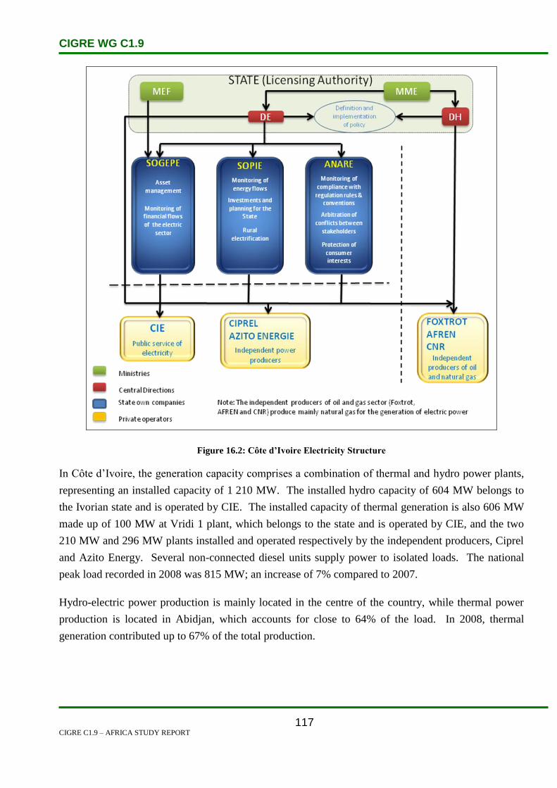
CIGRE WG C1.9
CIGRE C1.9 – AFRICA STUDY REPORT
117
Figure 16.2: Côte d’Ivoire Electricity Structure
In Côte d’Ivoire, the generation capacity comprises a combination of thermal and hydro power plants,
representing an installed capacity of 1 210 MW. The installed hydro capacity of 604 MW belongs to
the Ivorian state and is operated by CIE. The installed capacity of thermal generation is also 606 MW
made up of 100 MW at Vridi 1 plant, which belongs to the state and is operated by CIE, and the two
210 MW and 296 MW plants installed and operated respectively by the independent producers, Ciprel
and Azito Energy. Several non-connected diesel units supply power to isolated loads. The national
peak load recorded in 2008 was 815 MW; an increase of 7% compared to 2007.
Hydro-electric power production is mainly located in the centre of the country, while thermal power
production is located in Abidjan, which accounts for close to 64% of the load. In 2008, thermal
generation contributed up to 67% of the total production.

CIGRE WG C1.9
CIGRE C1.9 – AFRICA STUDY REPORT
118
Figure 16.3: Côte d’Ivoire Electricity Map
The geographic layout of the electrical infrastructure is shown in Figure 16.2. Côte d’Ivoire’s
transmission system is made up of 43 substations and approximately 4 400 km of transmission lines,
42% operated at 225 kV and the balance at 90 kV. For distribution, the system is based on roughly
18 700 km of medium voltage lines (15/33 kV) and 15 500 km of low voltage lines (220/380 V). The
synchronous frequency of the network is 50 hertz.
The transmission system is interconnected to the national electricity grids of Ghana and Burkina Faso.
CIE exports power to Togo, Benin and Burkina Faso, exchanges power with Ghana and supplies
power to two border towns in Mali.
The penetration rate of electricity in Côte d’Ivoire (number of electrified localities versus the total
number of localities in the country) is now 32% and the number of households with a subscription to
electricity compared to the total number of households is less than 25%.
16.2 Load and Energy Forecasting
In 2002, the electricity demand on the Côte d’Ivoire network was 614 MW peak demand and 3745
GWh annual energy consumption (average demand 428 MW). The figures for 2008 were 815 MW
peak demand and 5078 GWh annual energy consumption. In recent years (2000–2007), the average
growth rate of the load is about 4% due to turmoil in the country.

CIGRE WG C1.9
CIGRE C1.9 – AFRICA STUDY REPORT
119
The typical daily peak load is around 700 MW between 18:00 and 22:00, and the minimum load is
around 450 MW in the early morning. The seasonal variation is limited to 12%, with the peak in
April–May and the minimum in August.
There is evidence that economic growth has always had a significant impact on the rate of growth of
energy demand, particularly in developing economies. Indeed, analysis of past trends shows that, as a
whole, growth of electricity consumption in Côte d’Ivoire from 1960 to 1999, has been about two
times faster than the growth in gross domestic product (GDP). However, as depicted in Figure 16.3
below, since the year 2000 (beginning of political turmoil in the country) the relationship of electricity
consumption versus the GDP growth is difficult to identify.
Figure 16.4: Côte d’Ivoire’s Growth in Electricity Demand and GDP
The last major planning study conducted by the Ivorian electricity sector was done in 2001. This
project helped to establish the demand forecast and the master plan for generation and transmission
reinforcement for the period 2000 to 2015.
Regarding the demand forecast, an analytical forecast (or disaggregated) model was utilized. The
study begins with the segmentation of the demand for electricity usage by category and region using
technical data (sales, number of subscribers, electricity production, etc.), taking into account
demographics and economic data, surveys and existing studies. The evaluation of historical and
projected needs by sector and regional direction is also studied in the light of changing socio-economic
variables affecting the growth in demand. To do this, an analytical model for forecasting energy
demand and consumption by region, is developed for the whole country. For the purpose of planning
generation and transmission facilities, energy estimates are then converted into power, taking into
account losses and load factors on the network. Finally, sensitivity analyses are conducted to develop
alternative ‘high’ and ‘low’ scenarios.

CIGRE WG C1.9
CIGRE C1.9 – AFRICA STUDY REPORT
120
Figure 16.4 below illustrate the demand forecast obtained in December 2003
0
1000
2000
3000
4000
5000
6000
7000
8000
2000 2002 2004 2006 2008 2010 2012 2014 2016
Year
Co
nsu
mp
tio
n
MW
GWh
Figure 16.5: Côte d’Ivoire Forecasted Annual Maximum Demand and Consumption
The 2001 study predicted a 7% demand growth based on the available economical data. The more
recent forecast, however, estimates a lower growth rate of about 3%. The forecast for 2004 is 3 840
GWh, a growth rate of 2.1%. After the current unrest is over, Sopie expects electricity demand growth
to resume at 6% per year, which could lead to a 2020 demand of 1 570 MW.
16.3 Planning and Design Criteria
The latest studies for generation planning were based, in terms of the national economy, on the
assessment of the economic advantage of a number of options identified by stakeholders in the
electricity sector, namely:
The recovery of domestic resources of natural gas. This requires the evaluation of the sector
with the development of thermal power plants using gas turbines, fired by natural gas.
Development of the hydropower potential of the country in order to maintain a balance between
different energy sources used to meet demand.
Conversion to combined-cycle operation of the new Azito plant currently operated with two gas
turbines (2 x 148 MW) put into service in 1999 and 2000.
To do this, and in order to make an optimum economic choice, a reference scenario is first developed:
Starting from the current conditions of supply and generation data, and
Beginning with variants called ‘All Thermal’.

CIGRE WG C1.9
CIGRE C1.9 – AFRICA STUDY REPORT
121
Generation studies are done using a simulation model that provides technical and economic
optimization and determines the sequence of implementation of the type of generation at least
economic cost.
Table 16.1 below shows the existing generation capacity for the Côte d’Ivoire network. CIE operates
one thermal plant with an installed capacity of 100 MW and 6 hydro plants with a total installed
capacity of 604 MW. Two independent power producers operate two thermal plants with a total
installed capacity of 306 MW. The energy production mix is 75:25 thermal: hydro.
Table 16.1: Generation Capacity of the Côte d’Ivoire Network
Station Year Installed Capacity (MW)
Vridi TAG 5000(thermal) 1984 100
Azito (IPP) (thermal) 1999 296
Vridi CIPREL(IPP)(thermal) 1995/97 210
Ayame 1(hydro) 1959 20
Ayame 2(hydro) 1965 30
Kossou(hydro) 1972 174
Taabo(hydro) 1979 210
Buyo(hydro) 1980 165
Fayé(hydro) 1984 5
Total 1 210
16.4 Planning Approaches and Methods
The last major planning study conducted by the Ivorian electricity sector was done in 2001. This
project helped to establish the demand forecast and the master plan for generation and transmission
reinforcement for the period 2000 to 2015.
The main objective of the proposed transmission system recommended by the Ivorian master plan is to
meet at the lowest possible cost a number of criteria, including the most important which is to ensure a
strong supply to the main substations of the grid. Thus, in the absence of any element of the
transmission network, a situation which is referred to as the N-1 criterion, the load in various
substations of the grid must be supplied without any overloading of lines or transformers, and without
any unacceptable voltage drops.
Details of those criteria resulting from quality of service requirements are given below:
Voltage regulation. In considering the most onerous N-l contingency cases, the nominal
voltage of 90 kV at MV substations should be kept at a value of at least 81 kV. This represents
a maximum drop of up to 10% of the nominal voltage. This maximum deviation is expected to

CIGRE WG C1.9
CIGRE C1.9 – AFRICA STUDY REPORT
122
maintain an acceptable voltage at the 15 kV or 33 kV level, given the on-load tap changers of
high and medium voltage transformers that provide for a regulation of ± 15% and the voltage
drop between the primary and secondary windings under full load. In addition, a maximum
voltage not exceeding 10% above the rated voltages of 90 kV and 225 kV is considered
acceptable and safe for the lines and substations of the national electricity grid.
Overload capacity. In considering the most onerous N-l contingency cases, the transmitted
power on energized elements should not exceed 100% of the nominal capacity of the elements.
This planning criterion which is part of a long-term perspective is conservative, especially in
the case of substations where overload is provided in the design. However, it is better suited to
the environment of the Ivorian grid, characterized by relatively high ambient temperatures
compared to the normal standards applicable to the manufacture of transformers, and longer
restoration times in case of failure which are affected by geographic location. These concerns
lead to the provision of greater flexibility for operation.
Short circuit and dynamic stability. In view of the operating voltage levels of transmission lines
and statistics on the number of faults recorded on the transmission system, a permanent three-
phase fault on an outgoing line of a substation is considered sufficiently likely to check the
dynamic stability of the network under this contingency. This contingency is applied under the
most critical operating conditions and assuming the prior availability of all the elements of the
transmission system. The stability criterion requires that all generators maintain their
synchronism and remain in operation after the contingency.
Transient stability criterion. The total time of fault clearing for the purposes of applying the
stability criterion is set at 150 msec (7.5 cycles) at 90 kV and 120 msec (6 cycles) at 225 kV.
These times correspond to durations considered for new protection systems or in the case of
replacement of old protection systems on the grid.
16.5 Specific Technical Issues
The Ivorian power transmission grid is interconnected to those of Ghana and Burkina Faso through the
following lines:
Abobo (Côte d’Ivoire) – Prestea (Ghana) at 225 kV single circuit, 220 km long, commissioned
since 1983. This line conveys the energy sold to CEB for consumption in Togo and Benin.
Ferkéssédougou (Côte d’Ivoire) – Bobo Dioulasso (Burkina Faso) at 225 kV single circuit,
225 km long, commissioned since 2001.

CIGRE WG C1.9
CIGRE C1.9 – AFRICA STUDY REPORT
123
In 2002, only 26% of the population was connected to electric power. Out of 8 153 villages in the
country, only 2 017 had access to electricity. There is large potential for electrification; however the
turmoil in the country is suppressing the growth of the network.
16.6 Financing Issues
In Côte d’Ivoire, the pattern of financial flows in the sector set up in 1998 and still in force is as
follows:
The resources come from sales of electricity domestically and exported, and taxes on invoices.
These resources finance expenditure in the following categories:
1. Concessionaire remuneration for its services.
2. Purchase of fuel and electricity.
3. Investments for work related to operations.
4. Operating expenses of structures and management bodies and control of the sector.
5. Other spending in the sector.
6. Contributing to, or replenishment of, a reserve fund in the sector.
The expenses under 1, 2 and 3 are incurred by the CIE. Expenditure under 4, 5 and 6 are
incurred by SOGEPE.
The licensing authority (the state) and the concessionaire (CIE) have signed on 12 October 2005,
Endorsement No. 5 to the concession agreement for the generation, transmission, distribution, import
and export of electricity, for a period of fifteen (15) years.
This amendment was an opportunity to, among other things; improve the implementation and
financing of investments. The new provisions that remain to be implemented are:
The creation of three dedicated funds for investments, as well as a stabilization fund:
o The Renewal and Extension Fund, dedicated to investments of renewal, major
revisions, expansion and strengthening;
o The Rural Electrification Fund to finance rural electrification works;
o The Development Fund dedicated to investments on large infrastructure projects and
servicing of existing and future debt on these investments;
o The stabilization Fund, to absorb unanticipated expenses in the sector (WTI, dollar,
water) without penalizing the previous funds.

CIGRE WG C1.9
CIGRE C1.9 – AFRICA STUDY REPORT
124
The administration of these funds is entrusted to a Management Committee. This committee is
composed of representatives of the guardianship, CIE, and a representative of civil society.
Allocation of various funds:
o These funds are provided by a fee based on the kWh sales collected from domestic
customers.
o The amount of this fee and its allocation are pre-set by decree and revised during the
three-year tariff revisions.
o Bank financing can be used for part of the investment needs in the short term.
The changing role of CIE in managing investments:
o Project management is entrusted to CIE for renewal and extension works.
16.7 Human Resource Issues
The greatest challenge in human resources facing the electricity sector in Côte d’Ivoire is the problem
of reducing skills related to an ageing staff and massive retirements over the period 2007–2015. To
solve this problem, the authorities made the following proposals in 2007:
The extension of the retirement age for staff in the oil and electricity sectors.
The creation of a training centre for technicians in the fields of natural gas and electricity.
The establishment of bursaries for the training of engineers, and
The establishment of a common fund for the sectors of oil and electricity for the renewal and
strengthening of human resources.
16.8 References
1. http://www.ecb.org.na
2. www.absenergyresearch.com
3. http://www.nampower.com.na

CIGRE WG C1.9
CIGRE C1.9 – AFRICA STUDY REPORT
125
17. Democratic Republic of Congo
17.1 Electricity Industry Structure
The Democratic Republic of Congo (DRC) is a large country located in the middle of Africa, with an
area of 2 345 000 km2, 60 million inhabitants, very rich ground and a basin with immense forests
(122 000 000 hectares) made up of varied and rare species.
It has mining resources (copper, diamond, gold, cobalt, etc) and other building materials which make
DRC a geological treasure.
Although the DRC has 60% of Africa’s hydroelectric potential, only 7% of the country’s population
has access to electricity. Lack of local demand has led the DRC to export to SINELAC, Angola,
Burundi, the Congo, Rwanda, Zambia and Zimbabwe.
Société National d’Electricité (SNEL) is a vertically integrated monopoly, national power utility
established in 1970, responsible for generation, transmission and distribution of electricity in the
country under the governance of the Ministry of Energy (MoE).
Other organizations generating electricity include SINELAC which was established by Burundi,
Rwanda and Zaire to develop international electricity projects.
Apart from a number of smaller hydro power stations in the mining sector and a few thermal stations
belonging to private industry, there is currently no major private sector participation in the ESI. There
are no firm plans announced to liberalize the electricity sector.
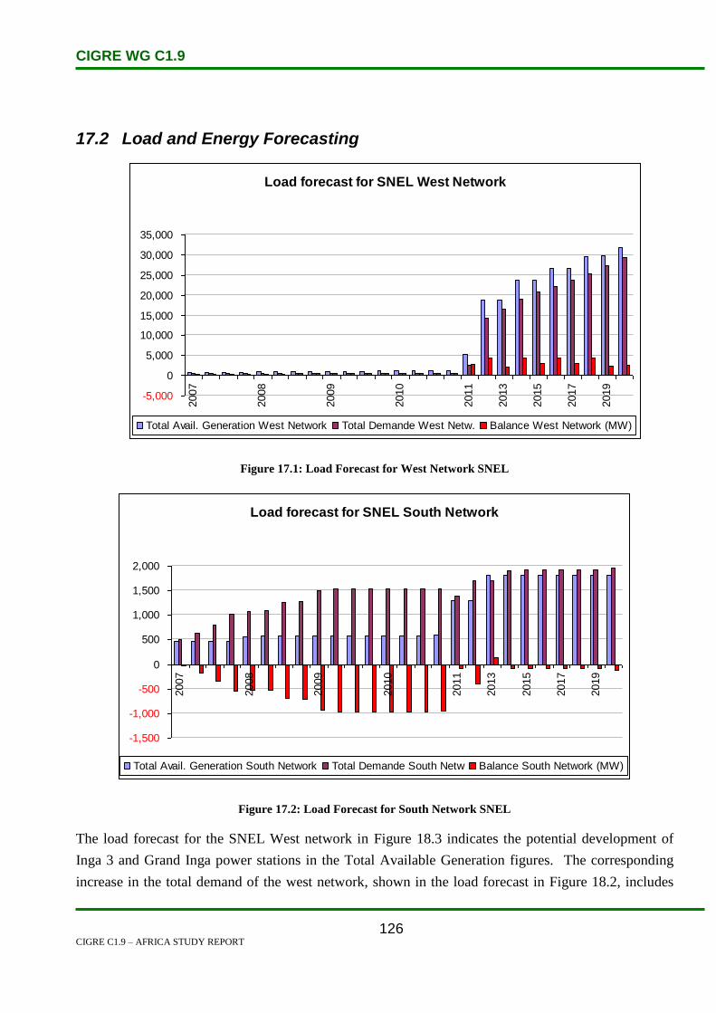
CIGRE WG C1.9
CIGRE C1.9 – AFRICA STUDY REPORT
126
17.2 Load and Energy Forecasting
Load forecast for SNEL West Network
-5,000
0
5,000
10,000
15,000
20,000
25,000
30,000
35,000
2007
2008
2009
2010
2011
2013
2015
2017
2019
Total Avail. Generation West Network Total Demande West Netw. Balance West Network (MW)
Figure 17.1: Load Forecast for West Network SNEL
Load forecast for SNEL South Network
-1,500
-1,000
-500
0
500
1,000
1,500
2,000
2007
2008
2009
2010
2011
2013
2015
2017
2019
Total Avail. Generation South Network Total Demande South Netw Balance South Network (MW)
Figure 17.2: Load Forecast for South Network SNEL
The load forecast for the SNEL West network in Figure 18.3 indicates the potential development of
Inga 3 and Grand Inga power stations in the Total Available Generation figures. The corresponding
increase in the total demand of the west network, shown in the load forecast in Figure 18.2, includes
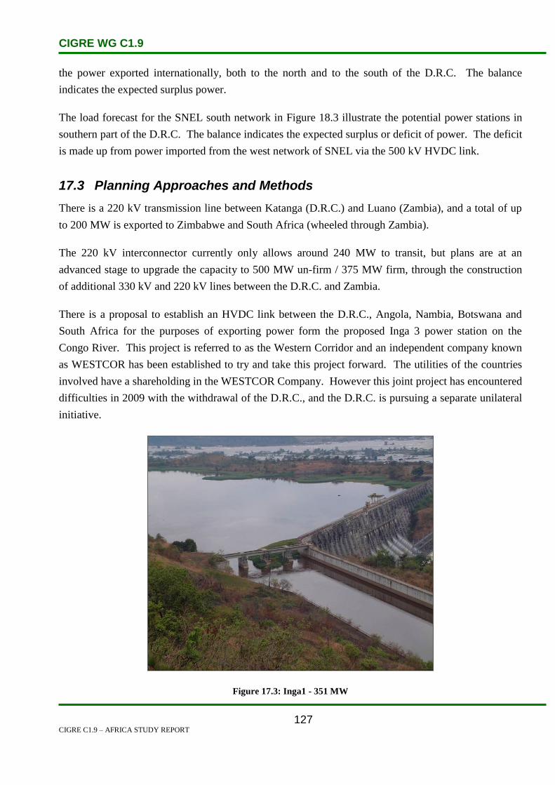
CIGRE WG C1.9
CIGRE C1.9 – AFRICA STUDY REPORT
127
the power exported internationally, both to the north and to the south of the D.R.C. The balance
indicates the expected surplus power.
The load forecast for the SNEL south network in Figure 18.3 illustrate the potential power stations in
southern part of the D.R.C. The balance indicates the expected surplus or deficit of power. The deficit
is made up from power imported from the west network of SNEL via the 500 kV HVDC link.
17.3 Planning Approaches and Methods
There is a 220 kV transmission line between Katanga (D.R.C.) and Luano (Zambia), and a total of up
to 200 MW is exported to Zimbabwe and South Africa (wheeled through Zambia).
The 220 kV interconnector currently only allows around 240 MW to transit, but plans are at an
advanced stage to upgrade the capacity to 500 MW un-firm / 375 MW firm, through the construction
of additional 330 kV and 220 kV lines between the D.R.C. and Zambia.
There is a proposal to establish an HVDC link between the D.R.C., Angola, Nambia, Botswana and
South Africa for the purposes of exporting power form the proposed Inga 3 power station on the
Congo River. This project is referred to as the Western Corridor and an independent company known
as WESTCOR has been established to try and take this project forward. The utilities of the countries
involved have a shareholding in the WESTCOR Company. However this joint project has encountered
difficulties in 2009 with the withdrawal of the D.R.C., and the D.R.C. is pursuing a separate unilateral
initiative.
Figure 17.3: Inga1 - 351 MW
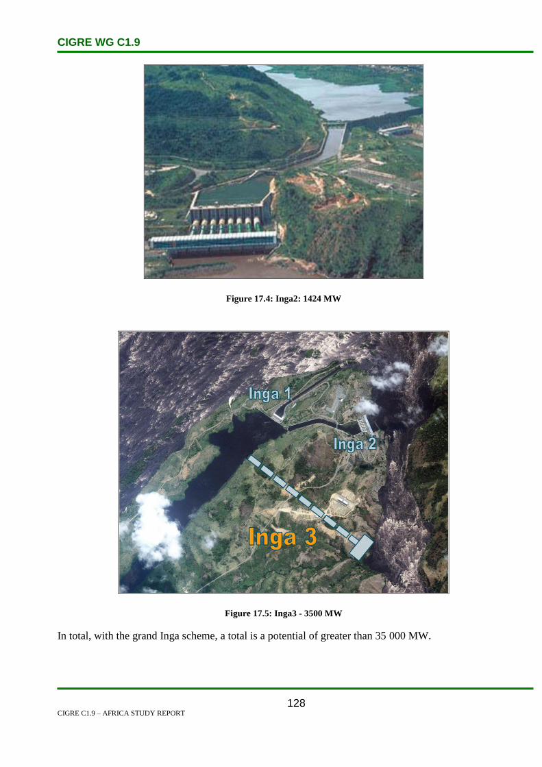
CIGRE WG C1.9
CIGRE C1.9 – AFRICA STUDY REPORT
128
Figure 17.4: Inga2: 1424 MW
Figure 17.5: Inga3 - 3500 MW
In total, with the grand Inga scheme, a total is a potential of greater than 35 000 MW.

CIGRE WG C1.9
CIGRE C1.9 – AFRICA STUDY REPORT
129
Figure 17.6: Location of Grand Inga
17.4 Specific Technical Issues
The main generating assets are located at the Inga site on the Congo River, with two major
hydropower stations with a total capacity of 1 750 MW. These are currently running at a capacity of
approximately 700 MW – less than half the total installed capacity of 1 775 MW – and are in urgent
need of rehabilitation.
Other major hydropower stations are located in the Shaba Province of the country, developed to supply
the mining loads in this part of the country.
An attempt has been made to establish a rehabilitation programme with the World Bank, but the
process is proving to be very long and drawn-out, although some progress has been made with Inga.
17.5 Financing Issues
The World Bank finances most of the DRC electricity projects.

CIGRE WG C1.9
CIGRE C1.9 – AFRICA STUDY REPORT
130
18. Djibouti
18.1 Electricity Industry Structure
Djibouti is located in East Africa with an estimated area of 23 000 km².
The total population of Djibouti has been estimated at 560 000 inhabitants, of whom 30% are refugees.
Of this number about 75% are urban-based, with 65% in the capital, and the balance being mostly
nomads.
The natural growth rate is 3% combined with an immigration rate of 3%.
The annual demographic growth rate is 6%. At this rate the population will double in 11 years.
Djibouti is bordered on the east by the Gulf of Aden, on the southeast by Somalia, on the south and
west by Ethiopia and on the north by Eritrea.
Load density per capita is 0.15 kW/person.
The electricity supply industry of Djibouti has been under the state owned electricity utility called
Electricite de Djibouti (EED). The utility reports under the jurisdiction of the Ministry of Energy and
Natural Resources. Electricite de Djibouti (EED) is responsible for generation, transmission,
distribution and sale of electricity country wide, and has a primary responsibility for the development
of geothermal resources for power generation.
In 1999 the government of Djibouti committed to privatize the national electricity utility.
Djibouti currently has installed electricity generating capacity of 85 MW, all of which is thermal (oil-
fired). In January 2001, US-based Geothermal Development Associates (GDA) announced that it had
completed a feasibility study on the development of a 30 MW geothermal power plant in Djibouti. The
study, which commenced in August 2000, established the commercial viability of the proposed
generating facility. The $115 million plant, to be located in the Lake Assal region west of the capital,
will be constructed on the build own operate (BOO) financing scheme.[1]
Electricite de Djibouti, the national electric company, has begun to remove aging diesel-fired
generating units. To continue to provide power to rural residents, the government, with the help of a
grant from a number of Arab financial institutions, are installing solar and wind capacity. The primary
goal of the project is to replace old diesel powered rural water pumps with new ones powered by
renewable resources, but excess energy will be used for electrification.[1]

CIGRE WG C1.9
CIGRE C1.9 – AFRICA STUDY REPORT
131
18.2 Load and Energy Forecasting
In 2004, Djibouti’s gross domestic product (GDP) amounted to about $1.6 billion based on purchasing
power parity. The growth rate of GDP was 3% in 2004, while electricity and water demand growth
was 5%.
In 2004, state-owned Electricité de Djibouti produced 266.6 GWh from four diesel-fired power plants
with capacity of 85 MW, compared with 263.6 GWh in 2003, 223.3 GWh in 2000 and 192.2 GWh in
1999.
From 1999 to 2004, the total consumption of electricity increased from 141.4 GWh to 223.9 GWh.
During the same period, industrial consumption rose from 66.7 GWh to 116.2 GWh.

CIGRE WG C1.9
CIGRE C1.9 – AFRICA STUDY REPORT
132
18.3 Planning and Design Criteria
No discussion available.
18.4 Planning Approaches and Methods
No discussion available.
18.5 Specific Technical Issues
The average cost of electricity for the domestic and commercial consumer is very high due to:
The deterioration of power generating equipment,
The use of expensive diesel fuel, and
The high transmission and distribution system losses.
The high cost of electricity impeded the development of the mining and construction materials sectors.
The Government of Djibouti plans to develop renewable energy sources to reduce costs. Resources of
geothermal energy have been estimated to be between 230 MW and 860 MW.
In 2003, the Djiboutian Government signed an agreement for a joint venture between Geothermal
Developments Associates of Nevada and Electricité de Djibouti, to create a 30 MW geothermal plant
near Assal. The plant is expected to have a capacity of 100 MW by 2015.
Geothermal areas include Arta, Assal, Bock, Dorra, Gaggade Plain, Hanle Plain, the Lake Abbe area,
and Tadjourah.
Assal’s wind-power capacity is estimated to be 100 MW.
The Djibouti grid is interconnected with Ethiopia.
Djibouti shows good potential for renewable energy development, especially in geothermal, solar and
wind. While some feasibility projects have already been undertaken to various degrees of
advancement, no operational use of these renewable sources has been made possible.
18.6 Financing Issues
Djibouti depends on international donors as well multi-lateral lending agencies such as the World
Bank.
In 2004 the African Development Bank loaned Ethiopia and Djibouti $32 million and $27 million,
respectively, to connect their power grids.
CIGRE WG C1.9
CIGRE C1.9 – AFRICA STUDY REPORT
133
18.7 Human Resources
In Djibouti, illiteracy is an especially severe problem. About 70% of the total population and 85% of
women are literate. There are also large inequalities in access to education in terms of regions, gender
and income levels. Moreover, the education system in Djibouti is very costly due to high unit costs for
school construction, learning and teaching materials, and teacher salaries. Also, 50% of the population
lives below the poverty line. [2]
18.8 References
1. http://www.energyrecipes.org/reports/genericData/Africa/061129%20RECIPES%20countr
y%20info%20Djibouti.pdf.
2. http://en.wikipedia.org/wiki/Education_in_Djibouti.

CIGRE WG C1.9
CIGRE C1.9 – AFRICA STUDY REPORT
134
19. Egypt
19.1 Electricity Industry Stucture
The Egyptian electricity supply industry is currently comprised of 15 separate government-owned
companies, all under the control and ownership of the Ministry of Electricity and Energy (MEE) via
the Egyptian Electricity Holding Company (EEHC), and several privately owned entities. These
include three BOOTs (Build, Own, Operate, Transfer), three private vertically integrated electric
companies located at the Red Sea, and three private generation/distribution utility companies
connected to the national grid in the Cairo and Alexandria areas. Refer to Figure 19.1 for the Egyptian
market structure.
EEHC is the main institution responsible for generation, transmission and distribution of electricity
throughout Egypt.
EEHC’s responsibilities include:
Implementation of electricity generation and transmission projects in urban areas (projects in
the rural areas are implemented by the Rural Electricity Authority),
Management, operation and maintenance of all major power stations,
Distribution and sale of electric power, and
Research and studies on matters related to the activities of the utility.
In addition to the EEHC, there are six Authorities operating in the electricity sub sector. These are:
Rural Electrification Authority (REA),
Hydropower Projects Executive Authority,
New and Renewable Energy Authority (NREA),
Atomic Energy Authority,
Nuclear Power Plants Authority, and
Nuclear Material Authority.
These Authorities are concerned with research activities and the execution of projects in their domain.
Once the projects are completed they are transferred to EEHC, which has all operational
responsibilities.
The Electricity Regulator’s responsibilities include:
Regulates and supervises all electricity generation, transmission, and distribution.

CIGRE WG C1.9
CIGRE C1.9 – AFRICA STUDY REPORT
135
Ensures availability of supply to users at the most equitable prices and considers environmental
issues.
Considers the interests of customers, producers, transmitters, and distributors.
Prepares for fair competition in the field of electricity generation, transmission, and distribution.
Prevents any monopoly within the electricity market.
Figure 19.1: Current Electricity Market in Egypt.
The structure of the targeted electricity market is shown in Figure 19.2. The vision for the Electricity
Supply Industry (ESI) is to open the market for bilateral contracts between producers and new
customers as well as existing customers in the medium term, and to allow for new entry of independent
distribution companies.

CIGRE WG C1.9
CIGRE C1.9 – AFRICA STUDY REPORT
136
Figure 19.2: Targeted Electricity Market in Egypt.
Statistical Data for Egypt – 2008
Table 19.1: Statistical Data for Egypt – 2008
Installed capacity by type of generation (MW) – 2008
Thermal 19436
Steam Turbines 11571
Gas Turbines 916
Combined Cycle 6949
Diesel 260
Hydro 2842
Renewables 305
Others
Total 22843

CIGRE WG C1.9
CIGRE C1.9 – AFRICA STUDY REPORT
137
Table 19.1 (contd) Statistical Data for Egypt – 2008
Yearly generation by type (GWh) – 2008
Thermal 108438
Steam Turbines 65732
Gas Turbines 657
Combined Cycle 42049
Diesel 350
Hydro 15510
Renewables 831
Others
Total 125129
Yearly Consumption (GWh
Residential 40271
Commercial 2860
Industrial 37045
Others 26419
Total 106595
Consumption per Capita (kWh) 1400
Population supplied (%)
Population growth (%) 2.4
Population 2008 (000) 76000
Maximum Load (MW)
Growth rate (%) 6.70
Time 21:00
Date 30 Jun 08
2008 19738
2007 18500
Exports (GWh) 814
Imports (GWh) 251
Electricity Losses (%)
Total 16.1
Distribution 9.1
Transmission 3.9
Generation 3.1

CIGRE WG C1.9
CIGRE C1.9 – AFRICA STUDY REPORT
138
Table 19.1 (contd) Statistical Data for Egypt – 2008
Transmission Lines (Km)
400–500 KV 2512
220–230 KV 14912
132–150 KV 2439
Substation Capacities (MVA)
400–500 KV 7765
220–230 KV 28850
132–150 KV 3427
19.2 Load and Energy Forecasting
The trend of electricity demand has generally followed the pattern of GDP growth.
During the period 1999/00 to 2003/04, the per-capita Gross Domestic Product (GDP) growth rate in
Egypt averaged 3.9% p.a. The electricity demand growth, which mirrors the economic growth,
averaged 6.2% p.a. over the same period.
During 2004/05 to 2011/12, the GDP is projected to grow on average by 5–6% p.a. and the
corresponding electricity demand by 7.5% p.a.
EEHC has prepared demand projections to 2012. High, medium and low case scenarios are used based
on the recent and past demand growth, population growth, and economic growth price elasticity of
demand. The high case scenario takes into account all development plans of Very High Voltage
(VHV) customers, while the medium case considered only approved projects of VHV customers for
the planning horizon. The low case assumed no new projects by VHV customers.
The following load forecasting methodologies are adapted by EEHC:
Historical trend analysis.
Sectoral analysis.
Econometric analysis.

CIGRE WG C1.9
CIGRE C1.9 – AFRICA STUDY REPORT
139
Figure 19.3: Daily Load Curve (Maximum Discharge) in Egypt
Figure 19.4: Daily Load Curve (Minimum Discharge) in Egypt

CIGRE WG C1.9
CIGRE C1.9 – AFRICA STUDY REPORT
140
Figure 19.5: Peak Load Curve 2003/2004 to 2004/2005 in Egypt
Table 19.2: Load Forecast in Egypt
Year Energy Demand
(GWh)
Energy generated
(GWh)
Peak Load
(MW)
1998/99 56530 68000 10919
1999/00 60806 73310 11736
2000/01 64647 77956 12376
2001/02 69176 83003 13326
2002/03 74990 88951 14401
2003/04 80697 94067 14735
2004/05 85781 101605 16454
2005/06 92431 109424 17731
2006/07 99534 117750 19050
2007/08 106484 126031 20372
2008/09 113881 134803 21771
2009/10 121519 143809 23211
2010/11 129361 153053 24677
2011/12 137438 162552 26191
The total energy generation is projected to rise from 94 067 GWh in 2003/04 to 162 552 GWh in
2011/12 registering an average growth rate of 7% per annum

CIGRE WG C1.9
CIGRE C1.9 – AFRICA STUDY REPORT
141
Peak load MW
0
5000
10000
15000
20000
25000
30000
0 5 10 15
year
MW
Peak load MW
Figure 19.6: Energy Demand Curve in Egypt
The generated energy and peak load of 2003/04 are taken as initial figures for the projection.
In addition to the domestic market, export potential is growing with increasing demand from Libya and
Jordan to which the country is interconnected.
19.3 Planning and Design Criteria
The total Installed Capacity in the year 2004/2005 was 18 544 MW, with a variation of 2.3% compared
with the previous year. The energy distribution can be seen in Figure 19.7, and is predominantly
thermal, with hydro and gas energy generation being relatively minor in comparison.
Figure 19.7: Generation Mix in Egypt

CIGRE WG C1.9
CIGRE C1.9 – AFRICA STUDY REPORT
142
Figure 19.8: Energy Forecast for Egypt
Table 19.3: Customers by Sector
Company Total No. of Subscribers
Industry 415171
Agriculture 60402
Gov. Utilities 165424
Houses 15687337
Commercial 1176203
Closed of postponed 2931030
Other 330205
Total 20765772
Based on studies recently carried out on transmission network planning and investment criteria, the
main planning and design criteria are summarized as follows:
Planning horizons vary from short term (few years ahead) to long term (up to 20 years ahead).
Egypt has recently achieved a Master Plan of its transmission system having the year 2030 as
the final target year.
The main technical criteria for transmission system development is the N-1 security criterion. It
is related to the loss of single circuit, transformer or generator, when after the occurrence of a
fault event the following consequences are to be avoided:

CIGRE WG C1.9
CIGRE C1.9 – AFRICA STUDY REPORT
143
o thermal overloading of branches,
o voltage deviations above permitted range,
o loss of stability,
o loss of load, and
o interruption of power transits,
Disturbance spreading over power system.
The N-2 criterion is not applied.
As for the security margins, some restrictions on the generating unit capability limits are imposed,
specifically on the Qmax and Qmin limits.
Concerning the capability of lines and transformers, the operational planning units in the national
dispatching centres usually do not define different thermal ratings for winter and summer operational
conditions, as it happens in Europe, but rather for normal and emergency conditions. Moreover,
different ratings are defined based on the age of equipment.
Generally, for reliability analysis the probabilistic approaches or the assessment of the probability of
N-1 events during transmission system planning are not considered. Methods used by transmission
planners are based on a deterministic approach and the probabilities of the occurrence of the various
events (network failures, generator dispatch, branches availability, etc.) are not taken into
consideration. Such an approach can be found only in some studies performed by foreign consulting
companies.
Load flow computations, static security analysis, short circuit calculations and system stability
analyses are performed during the planning process.
Uncertainties are mostly taken into account using multi-scenario analyses. The most important
uncertainties are:
new power plants size and location
generators engagement
load forecasts
country power balance
The North African power utilities do not have any specific criteria for interconnection line
construction, but commissioning of an interconnection requires a higher hierarchical level of analysis
where possible. Incoherency in planning criteria and system constraints must be solved, as well as all
aspects related to the engineering issues and coordination (e.g.: protection philosophy and relay

CIGRE WG C1.9
CIGRE C1.9 – AFRICA STUDY REPORT
144
settings). Considering the complexity of interconnection studies, quite often the prefeasibility and
feasibility studies for the different kinds of interconnections (HVAC, HVDC) are performed by foreign
consulting companies. The specific economic criteria for interconnection lines are based on difference
in electricity prices or on the overall change in system operational costs derived from different
interconnection options and different operating regimes of power systems.
19.4 Planning Approaches and Methods
Table 19.4: Generation Expansion Plan (2004–2012)
Plant Type Estimated Commissioning Year
2004/05 2005/06 2006/07 2007/08 2008/09 2009/10 2010/11 2011/12
Wind 85 120 120 120 100
Combined Cycle 1 250 750 1 750 1 500 500 1 000 1 000 1 250
Steam 1 300 650 650 650
Hydro 64
Solar/Thermal 150
Total 1 250 835 1 934 1 620 2 070 1 750 1 650 1 900
The Egyptian Electricity Holding Company (EEHC) has developed a Generation Expansion Plan to
meet the increased demand and system reliability in the Unified Power System (UPS) in the short-to-
medium term.
Table 19.5: Supply and Demand
The supply-demand analysis also takes into account the reserve margin required for maintenance,
forced outages and de-rating.

CIGRE WG C1.9
CIGRE C1.9 – AFRICA STUDY REPORT
145
The following are the existing interconnections:
Egypt-Libya interconnection. Implemented on 28/05/1998.
Egypt-Jordan interconnection. Implemented on 21/10/1998.
Syria-Jordan interconnection. Implemented on 08/03/2000.
Furthermore, Egypt is co-operating with other African nations to build another interconnection under
the Nile Basin Initiative (NBI), which encompasses Burundi, Eritrea, Ethiopia, Kenya, Rwanda,
Sudan, Tanzania, and Uganda.
Table 19.6: Interconnection
Figure 19.9: Import and Export

CIGRE WG C1.9
CIGRE C1.9 – AFRICA STUDY REPORT
146
Table 19.7: Investment Plan
The investment plan focuses on generation capacity expansion and expansion of the transmission and
distribution networks, at a total investment cost estimated at US$ 8 220 million.
Of the total investment cost, some US$4 341 million will be in foreign exchange and US$3 879
million in local currency.
N-security conditions
The basic assumptions related to the N criterion of the transmission network are:
The rating limits of transmission lines should be intended as maximum permanent currents.
In normal operating conditions, no overload of the transmission network is allowed.
No generator will be above its continuous reactive capability with possible restrictions decided
by the planner to account for operational constraints.
The loads are represented as constant active and reactive powers.
In normal operating conditions a long-term overload of transformers up to 10% of nominal
rating is allowed. A short term overload (less than 15 minutes) is allowed up to 20%.

CIGRE WG C1.9
CIGRE C1.9 – AFRICA STUDY REPORT
147
For the transmission system generally, unless otherwise specified, the maximum operating voltages are
as follows:
For 500 kV network maximum voltage is 525 kV.
For 400 kV network maximum voltage is 420 kV.
For 220 kV network maximum voltage is 231 kV.
For 150 kV network maximum voltage is 158 kV.
For 132 kV network maximum voltage is 139 kV.
For 90 kV network maximum voltage is 95 kV.
For 66 kV network maximum voltage is 72.6 kV.
The minimum operating voltages values are as follows:
For 500 kV network minimum voltage is 475 kV.
For 400 kV network minimum voltage is 380 kV.
For 220 kV network minimum voltage is 209 kV.
For 150 kV network minimum voltage is 142 kV.
For 132 kV network minimum voltage is 125 kV.
For 90 kV network minimum voltage is 85 kV.
For 66 kV network minimum voltage is 59.4 kV.
Operating Frequency:
The nominal frequency of North African countries is 50 Hz and its permissible variation range
under AGC is 50 ± 0.05 Hz.
Under normal operating condition the maximum permissible variation range is50 ± 0.2 Hz.
N-1 security conditions
The following criteria are applied under N-1 contingency conditions:
The transmission system should be planned such that reasonable and foreseeable contingencies
do not result in the loss or unintentional separation of a major portion of the network or in the
separation from the regional interconnected system.
During contingency conditions, a temporary overload of the transmission lines is allowed up to
10%.
A temporary overload of transformers is allowed in emergency conditions up to 20% during
peak hours.
The maximum post-transient voltage deviation is 10%.

CIGRE WG C1.9
CIGRE C1.9 – AFRICA STUDY REPORT
148
For the transmission system generally, unless otherwise specified, the maximum operating voltages
values are as follows:
For 500 kV network maximum voltage is 550 kV.
For 400 kV network maximum voltage is 440 kV.
For 220 kV network maximum voltage is 242 kV.
For 132 kV network maximum voltage is 145.2 kV.
For 66 kV network maximum voltage is 72.6 kV.
The minimum operating voltages values are as follows:
For 500 kV network minimum voltage is 450 kV.
For 400 kV network minimum voltage is 360 kV.
For 220 kV network minimum voltage is 198 kV.
For 132 kV network minimum voltage is 118.8 kV.
For 66 kV network minimum voltage is 59.4 kV.
Operating range frequency:
During N-1 contingency conditions, the maximum and minimum permissible frequencies are
50.4 Hz and 49.6 Hz respectively.
In the case of a severe incident, the maximum and minimum permissible frequency limits are
52 Hz and 47.5 Hz respectively.
Transmission Network Planning Probabilistic Approach
The probabilistic approach is seldom used in planning studies directly. However, the probabilistic
approach is being widely used in interconnection studies among the North African Countries (e.g.: the
MEDRING and the ELTAM studies).
Unless specific data is provided, the basic assumptions adopted concerning the unavailability of the
transmission system, are given in Table 19.8:
Table 19.8: Transmission Line Forced Unavailability Rate
VOLTAGE LEVEL
[kV]
UNAVAILABILITY RATE
[p.u./100 km]
500–400 0.005
220 0.0025
150–90 0.005

CIGRE WG C1.9
CIGRE C1.9 – AFRICA STUDY REPORT
149
As no reliability data on the transformers is available, standard hypotheses for these values are
assumed. It is assumed that the transformers have an availability of 99.5%.
Also for reactors and capacitors, records on their reliability are not normally available, hence standard
hypotheses for these values are adopted. More specifically, it is assumed that the reactive
compensation equipment has an availability of 99.5%.
Three different weather conditions, Normal, Bad and Stormy, are considered and, unless otherwise
specified, the parameters used to simulate the weather effect are set out in Table 19.9.
Table 19.9: Parameters of Weather Model
Weather Conditions Hours Ratio
[p.u.]
Coefficients
[p.u.]
Normal 0.9667 1.0
Bad 0.03 10.0
Stormy 0.003 15.0
As an indicator of the system adequacy, the annual value of Expected Energy Not Supplied (EENS)
due to unavailability in the transmission system and/or generation considering the constraints
represented by the transport capacities of the lines and active power limits of the power plants, is used.
A threshold value 10-4 p.u. is assumed for the EENS index related to insufficiency of the transmission
system due to a reduction in the transmission capacity of the network.
Economic evaluation in transmission-generation planning
The price of EENS for an economic evaluation can vary from 0.5 USD/kWh up to 2 USD/kWh.
The generation margins and the loss of load probability adopted for the reliability study are the
following:
Minimum generation margin reserve: 15%.
Loss of load probability (LOLP): 5–24 hrs/year. The highest value is valid whenever the
systems are operated in islanded mode.
Power reserve requirements and criteria
Power systems in North Africa are operated with a primary frequency control and a LFC (Load
Frequency Control). Primary and Secondary reserves are determined by each operator.
The policy for power reserve adopted in Egypt is set out according to the Operating Rules in the
Egyptian power system. The frequency and active power control is provided by the following means:
Automatic response from generating units operating in a free governor frequency sensitive
mode (Primary Reserve), and

CIGRE WG C1.9
CIGRE C1.9 – AFRICA STUDY REPORT
150
Automatic Generation Control (AGC) of generating units equipped with automatic load
frequency control (Secondary Reserve).
To ensure network security in the EEHC and other national systems composing the South-Eastern
Mediterranean synchronous pool (Libya, Jordan, Syria, Lebanon), after the most severe outage
considered, the total needed Primary Control Reserve is pre-determined at a value of 250 MW
composed of 150 MW thermal reserve and 100 MW hydro reserve.
As for the Secondary Reserve, there are 20 units of TPP and 10 units of HPP under the AGC. The goal
of the Secondary Control Reserve is to restore frequency and cross-border exchange to the set values.
The characteristics of actual operating reserves for power production are detailed below. They are
used as reference values.
Table 19.10: Operational Criteria for Definition of Operating Reserve in Egypt
Value
MW
Primary spinning reserve (within 30 sec) 250 100 MW Hydro Generation
150 MW Thermal Generation
Secondary spinning reserve (within 14.5 minutes):
In winter 350 Hydro-Thermal generation
175 Hydro-Thermal generation
175 Interconnection lines
Cold reserve (within 15 minutes) 600 Gas turbines
Type of Operating Reserve Comments
In summer
19.5 Specific Technical Issues
No discussion on specific technical issues was presented.
19.6 Financing Issues
A number of donors are involved in the electricity sector either directly through project finance, or
though policy dialogue. Some of the donors that support the EEHC’s generation expansion plan are:
Arab fund,
Opec fund,
Kuwait fund,
World Bank, and
AFDB and local funds.
Transmission investments are mostly financed through transmission fees, loans, internal sources and
very few by private investors.

CIGRE WG C1.9
CIGRE C1.9 – AFRICA STUDY REPORT
151
Economic Criteria (capital investment, IRR, NPV), in transmission network planning are applied. In
the economic evaluations, the reduction in the cost of the losses is usually estimated, but additional
benefits related to the reduction of congestion costs are also taken into account as well as the increase
of transmission service revenues.
Generally, the TSO’s or the VIU’s have not defined the cost of EENS and the applied values are
agreed for each study among the local experts. also taking into account the experience of the
Consulting companies, whenever they are involved in the execution of the transmission system studies.
Usually, the undelivered electricity costs across North Africa range between 0.5 and 2 US$/kWh.
Market-oriented transmission investments (merchant lines) and investments from a regional
perspective are not applied. National transmission networks are mainly planned according to technical
considerations and economic rationalization of new investments.
Egypt introduced IPP and public funding from 2003 onwards, and attracted investment in 6548 MW of
generation. Also, some manufacturing capabilities have been localized:
100% for distribution
80% for transmission
40% for generation
This has resulted in eventual lower cost. Egypt’s population has close to 100% access to electricity,
but growth rate and need for funding high.
19.7 Human Resources
Since there are a number of opportunities for cross-border interconnections in this region (refer to
Chapter 1.9), there have been interest from abroad in Egyptian energy generation development. These
parties include the African Union, European Union and the Norwegian government. The Consortium
of SNC Lavalin (Canada) and Parsons Brinckerchoff (UK) will consult in the study of the Regional
Master Plan and Grid Code. Mercados Energy Market International will be conducting a Capacity
Building Study promoting efficient and sustainable energy markets, designing effective regulation.
(Reference: Cigre Presentation: East Africa power pool).
CIGRE WG C1.9
CIGRE C1.9 – AFRICA STUDY REPORT
152
20. Equatorial Guinea
20.1 Electricity Industry Structure
Estimates of Equatorial Guinea's electricity generating capacity vary, with 15.4 megawatts (MW) of
certain installed capacity, and 5-30 MW of estimated additional capacity. Results of a DOE
questionnaire, official interviews and local site visits in 2004 have indicated that the actual installed
generating capacity may be seven times larger than what is currently reported, or approximately 131
MW. About 5.0 MW are located on the mainland, including 4 MW of oil-fired thermal capacity and 1
MW of hydroelectric capacity. On both Bioko Island and the mainland, electricity is generated by a
combination of thermal and hydroelectric plants. Although largely undeveloped, Equatorial Guinea is
estimated to have 11,000 MW of hydropower potential, of which 50% is deemed economically
recoverable.
The expansion of natural gas production at the Alba field in recent years has provided a convenient
fuel source for new power generation in the country. The 10.4-MW, natural gas-fired Punta Europa
plant began operation in 1999, supplying gas-fired electricity to Bioko Island. After upgrades in 2000,
the potential total capacity of Punta Europa rose to 28 MW, yet output remains constrained by the
original thermal capacity of the outgoing transmission line. An additional 4-6 MW of generation
capacity is currently under construction at the AMPCO complex on the island.
Equatorial Guinea's electricity sector is owned and operated by the state-run monopoly, SEGESA. The
government would like to privatize the state-run SEGESA, as a joint venture with a foreign utility, but
investors have shown little interest. SEGESA's power supply is unreliable due to aging equipment and
poor management, and consumers often experience prolonged blackouts. It operates the country's two
small electricity transmission networks, which comprise approximately 80 miles of high tension wire.
The network on the mainland serves the suburban area of Bata. The second, older distribution system
on Bioko connects Malabo to the port of Luba. The government has plans to expand this grid by 2010.
In 2003 Equatorial Guinea's electrical generation capacity was 15.4 megawatts (of which 80% is
thermal and 20% hydroelectric) and its electrical generation was 30 million kilowatthours.
Installed power capacity in 2001 was 5,000 kW; production in 2000 totaled 22 million kWh, of which
fossil fuels accounted for 91% and hydroelectric power for 9%. In 1983, China completed a
hydroelectric plant near Bata, with installed capacity of 3,200 kW. The 3.6 MW Riabo River
hydroelectric plant opened in 1989 and supplies most of the power on Bioko. As of 2002 a gasfired 4–
6 MW plant was under construction on Bioko.
In the 1990s Equatorial Guinea emerged as an important oil producer in the Gulf of Guinea. The first

CIGRE WG C1.9
CIGRE C1.9 – AFRICA STUDY REPORT
153
exploratory offshore petroleum well was drilled in early 1982. In 1991, production was initiated from
the offshore Alba gas condensate field in the Gulf of Guinea. Exports of oil began in April 1992. By
mid-1999, production amounted to about 90,000 barrels per day. Equatorial Guinea's total oil
production in 2001 averaged 181,000 barrels per day, a tenfold increase from 1996. Future oil
production was estimated at 120,000–300,000 barrels per day following an oil discovery at the La
Ceiba deep-water field in September 1999. A $450 million methanol plant on Bioko began production
of natural in 2001. [4]
20.1 Planning and Design Criteria
Construction of a turbo plant outside Malabo has improved Equatorial Guinea’s power situation. The
project was funded by the Government to an amount of 9 billion CFA and was managed by US-based
CMS-Nameco. The plant’s current capacity of 10.4 MW is thanks to a supply of natural gas from
Punta Europa, and has the potential to double if further developments are required.
Another gas-fired power plant is under construction at the AMPCO complex on Bioko. The 4 - 6 MW
project has the potential to increase Equatorial Guinea’s generating capacity significantly. The project
is being run on a build-operate-transfer (BOT) system. Gas from the Alba field and future gas finds
offshore of Bioko will power the plant. [3]
20.2 Planning Approaches and Methods
Extracts from http://www.estandardsforum.org and http://kpmgng.lcc.ch
Positive Trends
The government has invested heavily to upgrade and modernize the infrastructure.
Growth has been very rapid in recent years, spurred by higher oil prices.
The external debt is very modest.
Negative Trends
Equatorial Guinea is not a democracy. Civil and Political rights are severely limited.
Despite the recent economic boom, poverty remains pervasive.
The electricity sector is owned and operated by the state-run monopoly, Sociedad de Electricidad de
Guinea Ecuatorial S.A. (SEGESA). The power supply is unreliable because of aging equipment and as
a result, consumers often experience prolonged blackouts. The government has plans to upgrade and
modernize the electrical grid to make it more dependable. Many businesses have diesel and gasoline
powered generators as back-up sources of power supply. About 9 per cent of the electricity that is

CIGRE WG C1.9
CIGRE C1.9 – AFRICA STUDY REPORT
154
generated is derived from hydro-power and the remainder is from fossil fuels.
Increased opportunities exist in gas utilisation projects, as the Hydrocarbons Law has made it illegal to
flare gas. This has led to reduction in gas flared, which is now utilized in gas projects to generate
electric power.
Specific Technical Issues
No discussion on specific technical issues was presented.
20.3 Financing Issues
This country’s financial sector is underdeveloped. The government has plans to upgrade and
modernize the electrical grid to make it more dependable. This is due mainly because Sociedad de
Electricidad de Guinea Ecuatorial S.A. (SEGESA) is often unreliable. If the country decides to
increase their energy grid in the near future, they will have to seek foreign investment in order to fund
their projects. [1]
Equatorial Guinea has large reserves of natural gas which are estimated at 1.3 trillion cubic feet. That
is equivalent to 28.3 years of output at the 2006 level of 46 billion cubic feet. The bulk of the gas
reserves are located offshore Bioko Island. Eon of Germany, Fenosa of Spain and Galp Energia of
Portugal have formed a consortium that will work with Sonagas to construct a network of pipelines
and processing facilities on Bioko to export natural gas to Europe. In return,3 the companies will
receive long-term natural gas contracts. Eon will own 25 percent of the venture, Fenonsa and Galp
Energia will each own 5 percent, Sonagas will have a 50 percent interest and the remainder will be
owned by the government.. [1]
20.4 Human Resources
No discussion on human resources issues was presented.
20.5 References
1. www.estandardsforum.org
2. http://kpmgng.lcc.ch
3. http://www.mbendi.com/indy/powr/af/eq/p0005.htm
4. http://www.nationsencyclopedia.com/Africa/Equatorial-Guinea-ENERGY-AND-POWER.html

CIGRE WG C1.9
CIGRE C1.9 – AFRICA STUDY REPORT
155
21. Eritrea
21.1 Electricity Industry Structure
Eritrea is located on the horn of Africa (East Africa) and shares borders with Sudan, Ethiopia, Djibouti
and the Red Sea. The estimated population is 4.5 million. At national level 32% of the Eritrean
population has access to electricity (78% in the urban areas and 3% in rural areas)
The Eritrean Electric Corporation (EEC) is the main electricity supply utility that is responsible for
generation, transmission and distribution of electricity in Eritrea.
Some smaller villages have community diesel generators which can provide small amounts of
electricity to households. Photovoltaic (PV) electricity generation is being used in special applications
throughout the country.
The EEC operates under the Ministry of Energy and Mines (MEM). To extend the electricity supply
to the population throughout the country, the government of Eritrea is actively seeking private
companies to generate and sell power to the Eritrea Electric Corporation.
Currently there is no private power generation or transmission in the power sector.
21.2 Load and Energy Forecasting
Economic growth factors & load growth
Economic growth and growth of electric energy demand are interdependent. Factors on which
economic growth of a country fully depend are: availability of access roads, energy, communication,
water supply, educational level of the population, peace and stability in the region etc. Several of these
factors can be grouped as a general term – infrastructure. Development of infrastructure depends to a
large extent on the adequacy of available energy. The load growth follows the trend of development of
infrastructure. In Eritrea a lot of changes of infrastructure were made after independence. Hundreds of
kilometers of asphalt and gravel roads with hundreds of small, medium and large bridges were
constructed. Practically, we can barely say that all towns and villages are interconnected by road. Big
dams and micro-dams are built in several places in the country. This helped Eritrea to avoid full
dependence on natural rain water for agriculture. Stationary and mobile telephone communication
centres are constructed in almost all places in the country. That means the major factors for economic
growth are ready. These developments of infrastructure would not have been possible without energy.
On the other hand, the development of infrastructure considerably pushed up the power demand and
hence encouraged the need for power sources to grow.
CIGRE WG C1.9
CIGRE C1.9 – AFRICA STUDY REPORT
156
Load forecasting approach and methodology.
Up to 1998 the power demand in Eritrea was growing annually by 10% to 11%. From that it was not
difficult to forecast the power need in Eritrea up to the year 2015. Based on the forecast conducted in
the previous years, a new power plant of 88 MW was constructed in the years 1998–2000 (which was
commissioned in 2003).
Studying the trend of growth of power demand, the next step of forecast was to start from 2015.
However, due to the border conflict between Ethiopia and Eritrea, things were complicated and the
forecast anticipated has still not materialized.
An intensive load growth and power demand study is being conducted on the growing townships and
new industries to be included in the national plan. This will be prepared either by internal resources or
if necessary by employing consulting firms. This study (of the distribution system) becomes the base
for the gross load forecast for the overall power system in the country.
When there is a need for upgrading the existing transmission system or for the installation of a new
transmission system, frequently a new substation that interfaces the transmission system with the
distribution system has to be built. Reinforcement of the distribution system is determined by the
customer load density in the specific area.
In Eritrea there are several remote towns with isolated power plants. These power plants are helping
the towns to develop their overall economic activities, but on the other hand, these small power plants
are burden for EEC. The reason is that the plants are small and less efficient.
21.3 Planning and Design Criteria
EEC has an installed capacity of approximately 134 MW from several diesel power stations, which
supply mostly the larger cities and towns. Wind turbine generators are also delivering power in some
towns of Eritrea. In 2001, energy sent out by EEC was 224.4 GWh, while energy consumed by
customers was 186.7 GWh.
With regard to electricity consumption by sector, 57% is used by industry, 22% is used by the
household sector, and the remaining 21% is for commercial customers. Electricity consumption is
growing at about 10% per year.
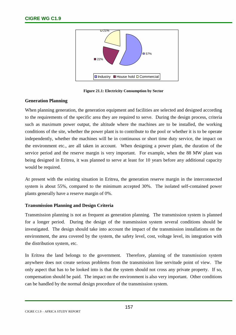
CIGRE WG C1.9
CIGRE C1.9 – AFRICA STUDY REPORT
157
57%
22%
21%
Industry House hold Commercial
Figure 21.1: Electricity Consumption by Sector
Generation Planning
When planning generation, the generation equipment and facilities are selected and designed according
to the requirements of the specific area they are required to serve. During the design process, criteria
such as maximum power output, the altitude where the machines are to be installed, the working
conditions of the site, whether the power plant is to contribute to the pool or whether it is to be operate
independently, whether the machines will be in continuous or short time duty service, the impact on
the environment etc., are all taken in account. When designing a power plant, the duration of the
service period and the reserve margin is very important. For example, when the 88 MW plant was
being designed in Eritrea, it was planned to serve at least for 10 years before any additional capacity
would be required.
At present with the existing situation in Eritrea, the generation reserve margin in the interconnected
system is about 55%, compared to the minimum accepted 30%. The isolated self-contained power
plants generally have a reserve margin of 0%.
Transmission Planning and Design Criteria
Transmission planning is not as frequent as generation planning. The transmission system is planned
for a longer period. During the design of the transmission system several conditions should be
investigated. The design should take into account the impact of the transmission installations on the
environment, the area covered by the system, the safety level, cost, voltage level, its integration with
the distribution system, etc.
In Eritrea the land belongs to the government. Therefore, planning of the transmission system
anywhere does not create serious problems from the transmission line servitude point of view. The
only aspect that has to be looked into is that the system should not cross any private property. If so,
compensation should be paid. The impact on the environment is also very important. Other conditions
can be handled by the normal design procedure of the transmission system.

CIGRE WG C1.9
CIGRE C1.9 – AFRICA STUDY REPORT
158
Eritrea at present has 71 km of 132 kV and 320 km of 66 kV transmission lines. Formerly, medium
voltage was 5.5 kV and low voltage was 127/220 volts. Now these voltages levels are out dated. At
present medium voltages are 15 kV and 33 kV while low voltage is 220/380 volts.
21.4 Planning Approaches and Methods
To improve the efficiency of the power systems and to promote energy conservation measures,
feasibility studies of major projects to rehabilitate the old transmission and distribution systems in
Asmara and Massawa have been finalized. The Massawa project is in the implementation process
while that of Asmara (the Asmara Power Distribution component of this project) commenced in 2004.
Financing is from the World Bank and other development partners.
A US$4 million project for a wind park has recently been constructed (2004–2007), to feed the Assab
grid and many decentralized stand alone or wind hybrid systems in the small towns and villages in the
area. GEF has pledged to cover 50% of this cost, and the Government and the private sector are
expected to cover the rest.
Implementation of the GEF funded project working on wind energy applications in coastal regions of
Eritrea is in progress.
The primary objectives in the energy sector are to:
Develop an efficient and environmentally sound and dependable energy production and supply
system, capable of supporting Eritrea’s growing economy in an affordable and sustainable way.
Reduce by half, between 2005 and 2015, the proportion of urban, semi-urban and rural
households which do not have access to adequate lighting.
Reduce by half, between 2005 and 2015, the proportion of urban, semi-urban and rural
households reliant on cooking methods that are not sustainable.
By 2015, provide an adequate, clean and efficient energy service to all educational, health and
clean water supply facilities.
Expand national electrification programmes through the consolidation and expansion of the
power grid system and generation capacities.
Increase the share of electricity in the national energy market.
Conduct and expand the rural electrification programme and establish the Rural Electrification
Revolving Fund to this end.
Develop power generation systems from the indigenous and cleaner sources of energy such as
gas, wind, solar, geothermal, and modern biomass.

CIGRE WG C1.9
CIGRE C1.9 – AFRICA STUDY REPORT
159
21.5 Specific Technical Issues
No discussion on specific technical issues was presented.
21.6 Financing Issues
The current energy system is ancient and it requires to be updated in order to match the power systems
as we know them today. The World Bank funded a $57.2 mln Power Distribution and Rural
Electrification Project between 2004 and 2009. It involved rehabilitating and expanding the electric
distribution system of Asmara, expanding rural electrification and boosting the efficiency of the
electric supply. [1]
Eritrea is very heavily dependent upon foreign assistance to help narrow the large trade deficit. In
2005,official development assistance totaled $355.2 mln, which was equal to 36.6% of
GDP.Remittances areanother important source of income that helps to partially offset the large trade
deficit and bolster private consumption. There is no up to date reliable data on remittances but World
Bank economist Dilio Ratha, an authority on remittances flows, has estimated that they are equal to
over 20% of GDP. About 850,000Eritreans live abroad [1].
21.7 Human Resources
No discussion on human resources issues was presented.
21.8 References
1. www.estandardsforum.org

CIGRE WG C1.9
CIGRE C1.9 – AFRICA STUDY REPORT
160
22. Ethiopia
22.1 Electricity Industry Structure
The Ethiopian Electric Power Corporation (EEPCo) is the Electricity Supply Company responsible for
electrical power generation, transmission, distribution and sales of electricity throughout the country.
EEPCo manages and operates power-generating facilities, the national transmission and distribution
grids, and is also responsible for the supply of electricity to more than 1 396 000 customers. Ethiopian
Electricity Agency (EEA) is a Federal organization that regulates the activities of electricity suppliers
for the supply of efficient, reliable and affordable electricity to the public. The Ministry of Mining &
Energy is responsible for the development of mining and energy in the country including the power
sector [2].
EEPCo, being the sole power producer, maintains two different power supply systems, namely the
Inter-Connected System (ICS) and Self-Contained System (SCS). The ICS is mainly supplied from
hydro power plants as wells as geothermal (steam) and thermal (diesel) sources. The SCS consists of
mini hydro power plants and a number of isolated diesel generating units widely spread all over the
country.
Figure 22.1 shows the national grid of Ethiopia [1]. Ethiopia is located on the Horn of Africa, it has an
area of 1.1 million km², and the population stands at 75 million. Ethiopia has an estimated hydro
power potential of 15 000–30 000 MW. The Ministry of Infrastructure is responsible for the
development of all infrastructure in the country including the power sector. The Ethiopian government
has taken several measures to address the power sector issues, and continues to make more changes.
The specific changes that have been made recently are embodied in two parallel efforts:
To de-lineate operation and regulatory functions, and
To liberalize the sector to promote private investment. The enactment of the investment
Proclamation No. 37/1997, particularly, allows the participation of domestic private investors in
the production and supply of electrical energy with an installed capacity of up to 25 MW. On
the other hand, production and supply of electrical energy with an installed capacity above 25
MW is open to foreign investors.
Positive news update:
o Positive experience in Ethiopia with electricity access increasing from 5% to 33% over
last 10 years due to investment from concerted effort to improve skills and

CIGRE WG C1.9
CIGRE C1.9 – AFRICA STUDY REPORT
161
professionalism and thereby attract funding for 3000MW of projects
Figure 22.1: National Grid of Ethiopia [1]
22.2 Load and Energy Forecasting
Acres Int’l (Acres 2000) has been involved in the study of future electricity demand. The study bases
its demand forecast on total GDP growth rates of 4.4% for year 2000, an average growth rate of 6.6%
per year for years 2001–2005 inclusive, an average of 4.4% per year for years 2006–2010 inclusive,
and 3.1% per year for years 2011–2025.
The study uses the income and price flexibility of electricity demand for the domestic (household),
commercial (services) and industrial tariff categories of consumers, along with the envisaged GDP
(income) growth rates for the respective consumer groups, to arrive at the annual demand growth rates
for each of the consumer categories. That way it arrives at electricity demand levels for each of the
major consumer categories for each of the years in the period 1999–2025. In 2004 EEPCo was
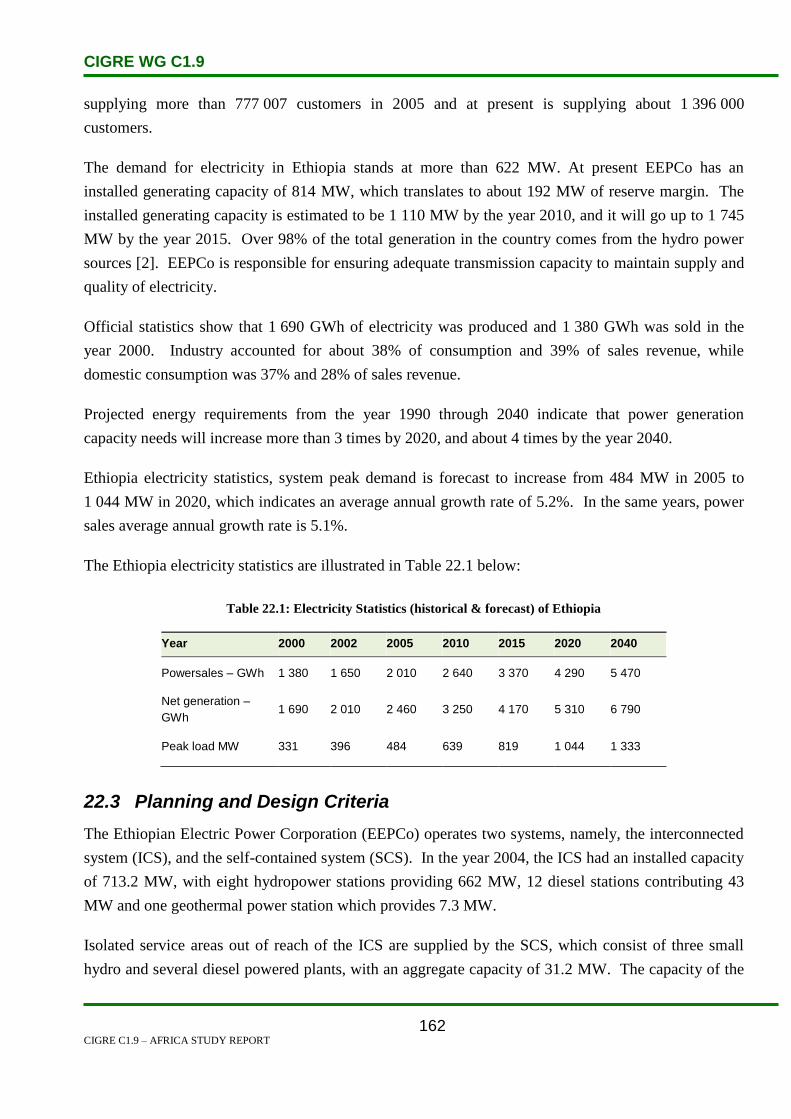
CIGRE WG C1.9
CIGRE C1.9 – AFRICA STUDY REPORT
162
supplying more than 777 007 customers in 2005 and at present is supplying about 1 396 000
customers.
The demand for electricity in Ethiopia stands at more than 622 MW. At present EEPCo has an
installed generating capacity of 814 MW, which translates to about 192 MW of reserve margin. The
installed generating capacity is estimated to be 1 110 MW by the year 2010, and it will go up to 1 745
MW by the year 2015. Over 98% of the total generation in the country comes from the hydro power
sources [2]. EEPCo is responsible for ensuring adequate transmission capacity to maintain supply and
quality of electricity.
Official statistics show that 1 690 GWh of electricity was produced and 1 380 GWh was sold in the
year 2000. Industry accounted for about 38% of consumption and 39% of sales revenue, while
domestic consumption was 37% and 28% of sales revenue.
Projected energy requirements from the year 1990 through 2040 indicate that power generation
capacity needs will increase more than 3 times by 2020, and about 4 times by the year 2040.
Ethiopia electricity statistics, system peak demand is forecast to increase from 484 MW in 2005 to
1 044 MW in 2020, which indicates an average annual growth rate of 5.2%. In the same years, power
sales average annual growth rate is 5.1%.
The Ethiopia electricity statistics are illustrated in Table 22.1 below:
Table 22.1: Electricity Statistics (historical & forecast) of Ethiopia
Year 2000 2002 2005 2010 2015 2020 2040
Powersales – GWh 1 380 1 650 2 010 2 640 3 370 4 290 5 470
Net generation –
GWh 1 690 2 010 2 460 3 250 4 170 5 310 6 790
Peak load MW 331 396 484 639 819 1 044 1 333
22.3 Planning and Design Criteria
The Ethiopian Electric Power Corporation (EEPCo) operates two systems, namely, the interconnected
system (ICS), and the self-contained system (SCS). In the year 2004, the ICS had an installed capacity
of 713.2 MW, with eight hydropower stations providing 662 MW, 12 diesel stations contributing 43
MW and one geothermal power station which provides 7.3 MW.
Isolated service areas out of reach of the ICS are supplied by the SCS, which consist of three small
hydro and several diesel powered plants, with an aggregate capacity of 31.2 MW. The capacity of the

CIGRE WG C1.9
CIGRE C1.9 – AFRICA STUDY REPORT
163
three small hydro power plants was only 6.2 MW. The total energy output capability of the ICS and
SCS were about 2 278.6 GWh, and 39.2 GWh, per year (2004). Table 20.2 illustrate the installed
capacity in Ethiopia in the year 2004.
Summary of installed capacity in MW (2004) is set out in Table 22.2:
Table 22.2: Installed Capacity and Generation Mix in Ethiopia – 2004
System Hydro MW Diesel MW Geothermal MW Total MW
ICS 662.6 43.3 7.3 713.2
SCS 6.2 25.0 - 31.2
ICS + SCS 668.8 68.3 7.3 744.4
22.4 Planning Approaches and Methods
The objective of planning is to establish a sustainable programme for expanding the population’s
access to electricity from 15% to about 20% by year 2012, and to improve the quality and adequacy of
the electricity supply. The Ethiopian government focuses on projects which will improve the
infrastructure necessary to meet Ethiopia’s expanded growth and distribution objectives. Table 20.3
illustrate the capacity increases for each estimated year. Some of the projects in which the government
is investing for continuous electricity supply are as follows:
Institutional and capacity increase,
Urban distribution and load dispatch,
Rural electrification and renewable energy promotion,
Biomass, and
Environmental improvement.
Table 22.3: Future Power Projects
Source Capacity MW Estimated year
Tekeze Dam 225 2007
Gilgel Gibe II 450 2008
There is a possibility of power trade between Ethiopia and adjacent countries (Sudan, Djibouti and
Kenya). The Eastern Nile Subsidiary Action Programme (ENSAP) is being planned jointly with Egypt
and Sudan to develop the region’s irrigation and hydropower generation. This will initially include
joint hydro projects between Ethiopia and Sudan on the Baro, Akobo and Birbir rivers. To promote
the sustainability and management of the Nile waters for a range of activities including power
generation, the Nile Basin Initiative has been developed. Subsequently it has also been decided to

CIGRE WG C1.9
CIGRE C1.9 – AFRICA STUDY REPORT
164
establish a regional office in Addis Ababa to co-ordinate the ENSAP.
CIGRE WG C1.9
CIGRE C1.9 – AFRICA STUDY REPORT
165
22.5 Specific Technical Issues
Most traditional energy sources are used for cooking and lighting, and thus energy consumption is
dominated by the domestic sector, which represents 89% of energy consumed, mostly rural homes.
Ethiopia has significant oil and gas reserves which are not being used. The vast majority of Ethiopia’s
existing capacity (85–98%) is hydroelectric power. The Ethiopian Electric Power Corporation
(EEPCO) plans to construct several new generating facilities to provide electricity to Ethiopia.
Currently, less than half of Ethiopia’s towns have access to electricity, although EEPCO electrified
more than eighty towns between 2001 and 2003. Since most of Ethiopia’s electricity is generated from
hydroelectric dams, the country’s power system is vulnerable to extended droughts.
EEPCO is currently constructing many more hydroelectric plants to supply power to currently un-
electrified households. Ethiopia has formulated its five-year MDGs-based medium-term development
plan entitled Plan for Accelerated and Sustained Development to End Poverty (PASDEP), which was
approved by the House of People’s Representatives in May 2006 following a wide range of
consultations with various stakeholders.
The 2005–2009 PASDEP is a continuation of Ethiopia’s first generation poverty reduction strategy
paper entitled Sustainable Development and Poverty Reduction Program (SDPRP), which covered the
period 2002–2004. The PASDEP has benefited from the MDGs Needs Assessment prepared with
support from UNCT, The World Bank and The Millennium Project.
The government noted that the MDGs are well integrated in its development plans, programmes, and
strategies, and the SDPRP and PASDEP are considered vehicles towards reaching the MDGs. As
indicated in many official reports, the country registered an impressive annual growth rate of about
11% per annum for the past four years ending in 2006–2007. This marks significant progress, not only
compared to the 7% annual growth target required to meet the MDGs, but also to realize Ethiopia’s
objective to become a middle-income country in the next two decades[7].
22.6 Financing Issues
In the year 2007, the World Bank Board of Executive Directors approved an International
Development Association (IDA) credit of US$130 million to help expand electricity access to rural
populations in Ethiopia. The Second Electricity Access Rural Expansion project aims to bring grid,
mini-grid and off-grid electricity access to 295 towns and villages and to provide such services as
lighting for schools and clinics, benefiting a total population of about 1.8 million.
By providing reliable and affordable electricity to rural communities, the project potentially will
enhance income-generating opportunities, improve health care and education, and boost agricultural
productivity. Better and cleaner lighting will also have a positive impact on the operating hours of the

CIGRE WG C1.9
CIGRE C1.9 – AFRICA STUDY REPORT
166
schools and on the hours available for children to study at night. Public street lighting will improve the
quality of life and the safety of the population living in the communities.
The Second Electricity Access Rural Expansion project will focus on the following components:
Grid Access Expansion will extend the grid to connect customers in rural towns and villages not
currently electrified. This will connect about 265 rural towns including 252 000 potential
customers and a population of about 1.1 million inhabitants. It will help install public street
lighting and also connect 286 000 new or indirect household customers to the grid distribution
system. To ensure affordability, poor customers will be offered 5-year-loans to defray the costs
of connection, and will receive energy efficient bulbs to reduce the monthly payments.
Off-Grid Access Expansion aims to connect 40 000 new customers in 30 rural towns, using
renewable technologies, and will provide some basic electric services (such as lighting and
cooling) to remote clinics and schools in very remote areas.
Capacity Building in key technical and institutional areas will support scaling up of
electrification and efficient use of energy. As part of the Lighting Africa effort, the project will
pilot 5 000 stand-alone systems using modern, energy efficient technologies such as LEDs.
Also, the project will work hand in hand with rural communities to increase post-harvest
agricultural productivity as a result of electricity access [5].
22.7 Human Resources
The Government of Ethiopia received a credit of US$41.05 million from the International
Development Association (IDA) to help the country finance its project of a new transmission line
connecting Ethiopia to Sudan’s power grid. The Ethiopia-Sudan interconnector will allow power
trading between the two countries, where just 6% and 22% of the respective populations have access to
electricity, thereby promoting Ethiopia’s power export revenue generation capacity. The transmission
line will run between the Ethiopian towns of Bahir-Dar and Metema and up to the border with Sudan
to connect the countries’ grids.
The project will also enable Sudan to replace domestic thermal generation with surplus hydropower
from Ethiopia, reducing Sudan’s greenhouse gas emissions. This will enable the two countries to
better integrate their reserve capacity, thus improving reliability on the interconnected system, and
ultimately providing savings on capital and operating costs.
The project will also invest in institutional strengthening and capacity building to improve the skills of
electricity company staff in Ethiopia in implementing and operating the transmission line, thereby
supporting Ethiopia’s ability to participate intensively in the development of a broader regional power

CIGRE WG C1.9
CIGRE C1.9 – AFRICA STUDY REPORT
167
market [6].
22.8 References
1. http://www.geni.org/globalenergy/library/national_energy_grid/ethiopia/index.shtml
2. http://www.eepco.gov.et/profile.html
3. http://www.bgr.de/geotherm/ArGeoC1/pdf/06%20Energy%20master%20plan.pdf
4. http://www.energy-ethiopia.org/downloads/Event_Pr_EEPCo.pdf
5. http://web.worldbank.org/WBSITE/EXTERNAL/COUNTRIES/AFRICAEXT/ETHIOPIA
EXTN
6. http://web.worldbank.org/WBSITE/EXTERNAL/NEWS
7. www.geni.org/globalenergy/issues/ethiopia/index.shtml

CIGRE WG C1.9
CIGRE C1.9 – AFRICA STUDY REPORT
168
23. Gabon
23.1 Electricity Industry Structure
Gabon is located in west-central Africa bordering the Atlantic Ocean at the Equator, between Republic
of the Congo and Equatorial Guinea. It has a population of about 1 485 832; this population study was
done in 2008. Gabon is known for its abundance in natural resources such as oil, manganese and iron
ore. It took Gabon over 70 years to come out of the French government policies. Gabon’s electricity
sector is operated by the Société d’Electricité et d’Eaux du Gabon (SEEG). Veolia (a French water and
power utility, formerly Vivendi) owns 51% of SEEG while 49% belongs to the SEEG employees and
the public. About 50% of Gabon’s population has access to electricity. SEEG supplies over half a
million people with electricity primarily in the cities of Libreville, Port Gentil and Franceville. 93% of
people who live in urban areas have access to electricity while only 35% of rural habitants have access
to this electricity. Estimated between 5000 and 6000 MW, the country’s hydroelectric potential places
Gabon in the 5th position among countries of the continent. The hydroelectric dams under construction
(Ivindo; Grand Poubara) and the prospects of sub-regional interconnection should enable Gabon to
export surplus power towards the sub-region in the long term.6
23.2 Load and Energy Forecasting
As of 2004, Gabon had 400 MW of installed generating capacity, of which 59% was geothermal, and
41 % was hydroelectric. In 2004, Gabon managed to generate 1.5Bkwh and used 1.4Bkwh. There are
two major suppliers of oil powered thermal energy in Gabon, i.e. The Nice Port station which
generates 60 (MW) and Owendo station which outputs 45 MW of energy.
Table 23.1: Energy in Gabon
Production Consumption Exports Imports Reserves
Electricity 1.52 billion kWh
(2005)
1.241 billion kWh
(2005)
0 kWh (2005) 0 kWh (2005)
Oil 266 000 bbl/day
(2005 est.)
13 000 bbl/day (2005
est.)
228 000
bbl/day (2004)
2 436 bbl/day
(2004)
1.748 billion bbl
(2007 est.)
Natural Gas 95.91 million cu m
(2005 est.)
95.91 million cu m
(2005 est.)
0 cu m (2005
est.)
0 cu m
(2005)
32.59 billion cu
m (1 January
2006 est.)
Source: CIA Factbook
The table above shows the energy consumption in comparison with the energy that was produced in
Gabon in 2005. As illustrated above, Gabon did not export electricity to other countries nor import
since they had a bit over the energy that they required.
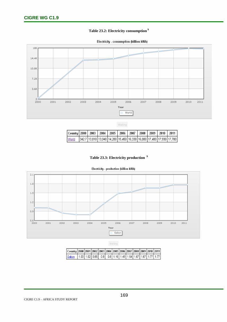
CIGRE WG C1.9
CIGRE C1.9 – AFRICA STUDY REPORT
169
Table 23.2: Electricity consumption 9
Table 23.3: Electricity production 9

CIGRE WG C1.9
CIGRE C1.9 – AFRICA STUDY REPORT
170
23.3 Planning and Design Criteria
Gabon has begun upgrading its electrical power and distribution facilities to meet industry and
residential demands, according to a government official involved in the project.
o meet growing energy needs, the government is planning to build more power-producing dams, which
the EIA says today account for only about 9 percent of all energy production. Most production now
comes from the use of petroleum or from biomass and waste.
Ongala said the government’s intention is to increase overall electrical power production from 374
MW to 1200 MW by 2020.7
23.4 Planning Approaches and Methods
The expected contribution of the operations programme to Gabon‟s development objectives by 2015 is
as follows;
The power system is strengthened and better equipped to support diversified growth. Energy
production is significantly increased and more reliable, and the active role played by the independent
power regulation authority, henceforth operational, contributes to the smooth functioning of markets
23.5 Specific Technical Issues
The experts also say Gabon’s plans – as with those for other African countries -- will need to provide
for the improvement of transmission facilities. In many countries, the electrical power infrastructure
was built before independence and poorly maintained since.
Much of that infrastructure is now obsolete. The development experts say energy plans should be all
encompassing. Rural areas need to take advantage of alternative energy sources, including solar, wind
and biomass.7
23.6 Financing Issues
Gabon has abundant hydropower that has been developed. The 160 MW Grand Poubara hydroelectric
project is under construction. It is located 650 km south east of the capital. The dam is being financed
by a CFAF 37.2 bn concessionary loan from China. The loan has a 3% interest rate and is repayable in
20 years. The hydro facility is being built by Sino Hydro. [5]

CIGRE WG C1.9
CIGRE C1.9 – AFRICA STUDY REPORT
171
23.7 Human Resources
It is a real problem, but one the government are providing solutions. They have just signed a
partnership agreement with an institution in Burkina Faso specialised in training for water sector
occupations. They are going to have discussions with other partners regarding training for the
electricity sector. The University of Franceville will also make a contribution to the training. In the
meantime, it is clear that for a given period that they will have recourse to foreign labour, which will
gradually be replaced. 8
23.8 References
1. http://www.eoearth.org/article/Gabon
2. http://www.reeep.org/index.php?id=9353&text=policy&special=viewitem&cid=68
3. http://www.mbendi.com/indy/powr/af/ga/p0005.htm
4. http://reegle.info/countries/GA
5. www.estandardsforum.org
6. http://www.afdb.org/fileadmin/uploads/afdb/Documents/Project-and-
Operations/Gabon%20-%202011-2015%20Country%20Strategy%20Paper.pdf
7. http://www.voanews.com/content/gabon-boosts-energy-power-generation--
141690993/181302.html
8. http://www.en.legabon.org/index.php?m=2&s=0&a=33
9. http://www.indexmundi.com/g/g.aspx?c=xx&v=81
CIGRE WG C1.9
CIGRE C1.9 – AFRICA STUDY REPORT
172
24. Gambia
24.1 Electricity Industry Structure
The Gambia is located on the west coast of Africa and is bordered by the republic of Senegal on all
sides except on the coast which faces the Atlantic Ocean. It is the smallest country on continental
Africa with a land area of 11 000 km2. The country is bisected by the River Gambia which runs from
the Atlantic Ocean right through the entire country. The population is 1.5 million, of which only 25%
have access to electricity. The rural population accounts for 4%. Access to electricity is concentrated
in the urban areas around the capital city of Banjul. This area is called the Greater Banjul Area (GBA).
The electricity sector in The Gambia is vertically integrated with one single owner and administrator of
electricity assets. The National Water & Electricity Company (NAWEC) is the main electricity supply
utility which is responsible for generation, transmission and distribution of electricity in The Gambia.
As a public enterprise, it has not operated on a commercial basis and cannot generate sufficient
financial resources to maintain and upgrade the systems. Although NAWEC has achieved financial
sustainability for its normal operations, it still lacks the resources to properly expand the electricity
system. Due to this, the system is ill equipped to satisfy the growing demand and needs substantial
investment to run efficiently. The available electric capacity of the Kotu Power Plant is concentrated
in the Greater Banjul Area (GBA) and is not sufficient to serve the existing demand.[3]
The energy sector in the Gambia is under the direct authority of the Presidency of the Head of State,
which exercises its control through the Permanent Secretary. The Gambian power system is still very
modest and is composed of seven autonomous sub-systems scattered throughout the country. These
sub-systems are equipped with diesel units that supply customers via medium and low voltage
networks.
There is a major diesel generating plant at Kotu Power Station and an IPP at Brikama, all within the
GBA. Some stand-alone diesel generating plants are also in operation in six rural communities
ranging from 180 kW to 1.4 MW per plant making a total of 4.26 MW installed capacity in the
provinces providing electricity to households. Photovoltaic (PV) electricity generation is also being
used in special applications throughout the country, such as in provincial boreholes supplying water to
rural communities and for electricity supply to clinics. NAWEC operates under the Department of
State for Energy and has a Managing Director and a Board of Directors who advise him. The Gambia
Government is actively working to extend power supply to all parts of the country.
The Gambia signed the first Power Purchase Agreement (PPA) with an Independent Power Provider
(IPP) and passed into law a new Electricity Act in 2005. The Act has opened up the generation
component of the electricity business to investors and IPPs. The Act is expected to set the stage for the

CIGRE WG C1.9
CIGRE C1.9 – AFRICA STUDY REPORT
173
end of NAWEC’s monopoly, increase competition, and improve services. The Act also envisages
private sector participation in the distribution of electricity [3].
Figure 24.1 shows the proposed 225 kV line that will link The Gambia with Senegal, Guinea, and
Guinea-Bissau as part of the Organisation pour la Mise en Valeur du Fleuve Gambie (OMVG).
Figure 24.1: The OMVG Network [1]
The Electricity Act regulates power generation, transmission, distribution and marketing in Gambia.
The Act determines the standards relating to the sector and attributions of the Department of State. It
sets the conditions for tariffs and granting of licenses. [4]
Public stakeholders [11]
The public stakeholders involved in the Gambian electricity sector are, among others:
The Presidency of the Head of State, through a Permanent Secretariat, ensures technical
guardianship and is responsible for drafting and enforcing the general policy of the sector,
CIGRE WG C1.9
CIGRE C1.9 – AFRICA STUDY REPORT
174
The Public Utilities Regulatory Authority (PURA) is a multi-sectoral regulatory body, an
independent authority. It was created in February 2005 and is chiefly responsible for granting
licenses to operators, fixing tariffs, defining quality and service standards, and also reviewing
and approving investment plans,
The Gambia Divestiture Agency (GDA) is responsible for monitoring the state disengagement
from companies, particularly from public enterprises,
The Gambia Renewable Energy Centre (GREC) is in charge of research and development,
information.
The sector operators [11]
The historical operator remains the National Water and Electricity Company (NAWEC), which is a
public limited company. 97% of its capital is held by the Gambian state, 1% by the Social Security
and Housing Finance Corporation (SSSFC), 1% by the Gambia Telecommunication Company
(GAMTEL) and 1% by the Gambia Port Authority (GPA). Its prime mission is supplying the national
territory with water and electricity.
Independent Power Producers are also interested in the generation segment.
24.2 Load and Energy Forecasting
NAWEC has an installed capacity of 42 MW at the Kotu Power Station and 24 MW at the IPP station
in Brikama. NAWEC produced 138.12 GWh of electricity in 2006 and 62.69 GWh in 2007 from Kotu
Power Station alone, which serves only the Greater Banjul Area. The apparent drop in production in
2007 is due to the operation of the IPP. It is projected that demand will grow by 35% in the Greater
Banjul Area over the next decade and by 10% in the rural areas as the electricity supply system is
gradually extended country wide.
The methodology employed in load/demand forecast is:
Historical trend analysis.
Electrification analysis.
Real time load measurements.
End use analysis.
Power supply and demand [11]
NAWEC power system is relatively simple and is essentially centred around the main urban centre of
the Greater Banjul Area where most of the energy produced is consumed. The Gambia’s six province
centres total an installed capacity of 2 MW, of which 1 MW is available. Its offices only work for 14

CIGRE WG C1.9
CIGRE C1.9 – AFRICA STUDY REPORT
175
hours a day. The self-generation capacity of hotels and some industrial units is very important and
credited with a 56 MW installed capacity. The NAWEC power system is not interconnected to any
other power system of the region.
Generation [11]
In 2005, the NAWEC gross power generation amounted to 156.268 GWh as against 128.061 GWh in
2004, i.e. an increase of 22%.
Efficiency of the power system [11]
Net energy delivered to the distribution network in 2005 stood at 91.889 GWh as against 80.233 GWh
in 2004, which is a 14.5% increase. The gross efficiency of the network amounted to 58.8% in 2005 as
against 62.65% in 2004, which is a 3.85% decrease. The called-up peak capacity (under load shedding
conditions) on NAWEC network was 25.8 MW in 2005 as against 25.1 MW in 2004, i.e. a 2.78%
increase. This peak capacity was determined on 22 October 2005 at 08:00 pm. The estimated peak
demand is 63 MW.
Electricity demand forecasts [11]
In 200 NAWEC total generation was obtained from its own thermal facilities located at Kotu in
Banjul suburb. The average growth rate is 7.8% per year for energy demand, and 8.0% for capacity
demand.
Table 22.1 below, shows the electricity demand forecasts in peak capacity (MW) and in energy (GWh)
of The Gambia.
Table 24.1: The Gambian Power Demand Forecast (MW, GWh) [11]
2006 2007 2008 2009 2010 2015 TMC (2006-15)
Energy (GWh) 368.97 416.28 463.58 501.42 596.03 724.28 7.78%
Capacity (MW) 78 88 98 108 126 156 8.0%
Generation fleet
In 2005, the total generation of NAWEC installed capacity was 48.8 MW, of which 32.2 MW was
available, that is 65.9% of the total installed capacity. The generation fleet is essentially thermal and is
located at Kotu in Banjul suburb. The configuration of Kotu’s thermal plant is shown in below.
Figure 24.2 is a graphical representation of electricity net generation from 1980 to 2006.

CIGRE WG C1.9
CIGRE C1.9 – AFRICA STUDY REPORT
176
Table 24.2: The Gambian Power Demand Forecast (MW, GWh)
Figure 24.2: Electricity Net Generation [10]

CIGRE WG C1.9
CIGRE C1.9 – AFRICA STUDY REPORT
177
Transmission and distribution networks [11]
NAWEC power transmission and distribution lines totaled 261 km in 2005 made up of 106 km at
33 kV and 155 km at 11 kV. The low voltage (LV) network, totaled 443 km of line. The NAWEC
installed transforming capacity stood at 144 MVA in 2005, made up of 68 MVA on the transmission
system and 76 MVA on the distribution system.
Figures 24.3 and 24.4 below are graphical representations of electricity consumption and installed
capacity respectively from 1980 to 2006.
Quality of service of the transmission and distribution network [11]
NAWEC cumulated global losses on the generation, transmission and distribution system were 30% in
2005.
Figure 24.3: Electricity Nett Consumption [10]

CIGRE WG C1.9
CIGRE C1.9 – AFRICA STUDY REPORT
178
Figure 24.4: Electricity Installed Capacity [10]
24.3 Planning and Design Criteria
Minimum transmission system security standard [5]
All transmission networks should be designed to achieve at least a deterministic N-1 security standard,
i.e. supplies to all loads should be uninterrupted for the loss of a single network component.
Deviations from this standard are permissible subject to regulatory approval.
General rules for an acceptable level of security for the connection of power stations or generators
should be established by the transmission system operator (e.g. N-1 security where the power station is
greater than a given size). The possibility of common mode failure should be eliminated at the design
stage wherever possible.
Minimum distribution system security standard [5]
General rules for an acceptable level of security for the different parts of the distribution system should
be established by the distribution system operator taking account of fault rate, restoration times, and
the requirements of the distribution system performance standards. For example, the system could be

CIGRE WG C1.9
CIGRE C1.9 – AFRICA STUDY REPORT
179
split according to the size of MW demand fed from a particular area of the network, or the number of
customers connected, and different security criteria applied to the different demand categories.
Minimum transmission voltage standard [5]
The voltage of all transmission networks at operating voltages of less than 400 kV should be
maintained within +/-10% of nominal. The voltage of transmission networks operating at voltages of
greater or equal to 400 kV should be maintained within +/-5% of nominal. Deviations from these
limits can be agreed where the normal voltage at a customer connection point is not the nominal
voltage.
24.4 Planning Approaches and Methods
Transmission and distribution planning studies using computer load flow models should be undertaken
to investigate the effects of disconnecting single generation units, transmission circuits, transformers,
busbars, shunt capacitors/reactors and other devices on the ability to supply the system maximum
demand, without infringing planning standards for voltages or equipment ratings.
Planning studies using computer models of the transmission system suitable for undertaking load flow
and transient stability studies should be undertaken to investigate the effect of the connection of power
stations in respect of system outages and on transient stability.
24.5 Specific Technical Issues
The core problems and objectives affecting the electricity sector are the following:
Increase of generating capacity that is presently inadequate and unable to meet the demand.
The shortfall is estimated to range between 15 MW and 30 MW. The government therefore
seeks foreign and local partnerships in increasing generation capacity [2].
Capital investment to improve the poor state of the transmission and distribution systems which
results in high technical losses and un-metered consumption estimated at about 40% [2].
Improving efficiencies so as to reduce the extremely high cost of energy, estimated at an
average of US$0.18 [2].
Due to lack of resources, NAWEC has been unable to meet a growing demand, particularly
from a thriving tourism industry [8].
Chronic capacity shortages and the resulting unreliable standard of service have resulted in
daily load shedding and network overloading [8].
Technical losses are high at about 40% [8].
The average electricity tariff is high, at US$0.25 per kWh, with large consumers cross-

CIGRE WG C1.9
CIGRE C1.9 – AFRICA STUDY REPORT
180
subsidizing small customers [8].
In 1993, the government decided to involve the private sector in the management of NAWEC
through a leasing arrangement. Relations with the private partner soured rapidly because of ill-
defined contractual clauses regarding government obligations to finance or guarantee
investments and an inadequate regulatory framework [8].
There is a feasibility study underway for the electrification of the western region of The Gambia and
the possible upgrading of the GBA network to accommodate higher transmission voltage levels.
Studies are also underway for the eventual connection of The Gambia to the West African Power Pool
(WAPP).
NAWEC proposes to erect an additional diesel power plant in Brikama with an initial capacity of 10
MW, to be eventually increased to 30 MW.
24.6 Financing Issues
NAWEC has several development partners and has obtained funding for electricity projects from
AfDB, Kuwait Fund for Arab Economic Development (KFAED), Arab Bank of Economic
Development in Africa (BADEA), OPEC Fund, Islamic Development Bank (IDB) and the ROC.
The National Electric Power Company of Jordan (NEPCO) has been appointed to put into place an
advanced electricity network in the Gambia. NEPCO has established an agreement of US$310 000
with NAWEC [6].
The Rural Electrification Project was co-financed by BADEA and the IDB [7].
24.7 Human Resources
The Gambia regularly utilizes foreign companies to assist with the planning and design of the
electricity network,
In 2007, a Jordanian company called the National Electric Power Company (NEPCO) signed an
agreement with NAWEC to help upgrade the electricity sector. Experts from the planning and transfer
plant unit in NEPCO will conduct a feasibility study into the upgrading of the electricity sector [9].
24.8 References

CIGRE WG C1.9
CIGRE C1.9 – AFRICA STUDY REPORT
181
1. Nexant Inc. ‘West Africa Regional Transmission Stability Study’. Volume 2: Master Plan.
URL http://www.ecowapp.org/Volume 2 Master Plan - Final.pdf. Last accessed:
18 August 2009.
2. The Energy Sector. ‘Electricity, LPG and Renewable Energy’. URL:
http://www.gambia.gm/Energy_Sector/energy_sector.html. Last accessed: 5 August 2009.
3. dgmarket Tenders Worldwide. ‘Electricity and Water Sector Study and Assessment of
Options for Private Sector Participation in the National Water and Electricity Company
Limited (NAWEC)’. URL: http://www.dgmarket.com/tenders/np-notice.do~1396216.
Last accessed: 6 August 2009.
4. Yahya A.J.J. Jammeh. ‘Electricity Act, 2005’. URL:
http://pura.gm/documents/electricity/ElectricityAct.pdf
5. Public Utilities Regulatory Authority (PURA). ‘Guidelines on Minimum Quality of
Service and Relaibility Standards for Electric’.
URL: http://pura.gm/documents/electricity/PURA Minimum Quality Service
Reliability.doc. Last accessed: 6 August 2009.
6. The Gambia Experince. ‘Gambia unveils advanced electricity scheme’. URL:
http:/www.gambia.co.uk/Gambia-News/2007/12/18384819/Gambia-unveils-advanced-
electricity-scheme.aspx. Last accessed: 11 August 2009.
7. African Development Bank. ‘The Gambia: 2002–2004 Country Strategy Paper Update’.
URL: http://www.afdb.org/fileadmin/uploads/afdb/Documents/Project-and-
Operations/ADB-BD-IF-2006-272-EN-GAMBIA-CSP-UPDATE.PDF. Last accessed: 11
August 2009.
8. The International Monetary Fund and the International Development Association. ‘The
Gambia’. URL: http://www.imf.org/external/np/hipc/2000/gmb/gambiadp.pdf. Last
accessed: 11 August 2009.
9. Gambia News. ‘NAWEC chooses NEPCO to upgrade electricity sector’. URL:
http://www.gambianow.com/news/General/Gambia-News-:-NAWEC-chooses-NEPCO-to-
upgrade-electricity-secto.html. Last accessed: 18 August 2009.
10. Energy Information Administration. ‘Swaziland Energy Profile’. URL:
http://tonto.eia.doe.gov/country/country_energy_data.cfm?fips=GA. Last accessed:
11 August 2009.

CIGRE WG C1.9
CIGRE C1.9 – AFRICA STUDY REPORT
182
11. West African Power Pool. ‘2005 Performance Indicators of WAPP Member Utilities
Power Systems’. URL: http://www.ecowapp.org/WAPP PDFS/KPI-ENG.pdf. Last
accessed: 11 August 2009.

CIGRE WG C1.9
CIGRE C1.9 – AFRICA STUDY REPORT
183
25. Ghana
Ghana was the first African team to qualify for 2010 World Cup in South Africa and the only African
team to make it to the second round.
25.1 Electricity Industry Structure
Figure 25.1: National Grid of Ghana [1]
The development of the Ghana electricity sector took place over three successive periods [2], [3]:
The period prior to Akosombo (1914–1967)
o Before the refurbishment of Akosombo’s hydro electric plant, Ghana’s power
generation was by means of diesel units, scattered throughout the country and
supplying isolated networks. The first public power utility was established in 1914 in
the Sekondi region, in central Ghana. That system was installed to be exploited all
along the railway network by the railway company, The Gold Coast Railway
Administration. That type of power system was developed and quickly expanded to
other areas such as Takoradi in 1928. Concurrently, the public works services, Public

CIGRE WG C1.9
CIGRE C1.9 – AFRICA STUDY REPORT
184
Works Department (PWD) became involved in the electrification task of other
localities of the country.
o As of 1947, the Electricity Department of the Ministry of Public Works and Housing
was created to take over the electricity activities of the Public Works Department and
The Gold Coast Railway Administration. One of the relevant achievements of the
department was the construction of the Tema 1.95 MW thermal plant in 1956, and its
gradual expansion from 1961 to 1964 to a 35 MW capacity. The plant was then the
largest diesel plant in Africa. It supplied the Tema area and the major part of Accra via
a 161 kV line.
The period known as Hydro Years.
The Volta River Authority (VRA) was established in 1961 by the enactment of Act 46 relating
to the harnessing of the Volta River, Volta River Development Act. VRA was assigned the
role of harnessing the potential of the Volta River, and ensuring exploitation of generation
facilities and power transmission in Ghana. Construction works of Akosombo dam commenced
in 1962 to be completed in 1966, with an initial installed capacity of 588 MW. Two other units
were added to the dam, thus increasing its installed capacity to 912 MW.
The VRA commissioned Kpong hydro electric dam in 1982, at Akuse, downstream of
Akosombo dam, with a 160 MW installed capacity.
The period known as Thermal Completion.
Ghana experienced a severe drought in 1983 which caused a critical deficit in electric energy.
The VRA consequently initiated a study on the expansion plan of its generation and
transmission system. The study was finalized in 1985 and confirmed the need to build thermal
plants to meet the ever growing demand and to supplement hydro generation. From 1990 to
2000, the Ghana government embarked on reforms of its electric power sector with a view to
making it more efficient and accessible to private operators. These reforms were expressed by
the creation of new public stakeholders and the adoption of a series of Acts and legal texts, of
which the main ones are listed below:
o The Strategic Framework for Power Sector Development Policy in January 1994.
o Setting up of the Power Sector Reform Committee (PRSC) to co-ordinate the drafting
and implementation of reforms, in September 1994.

CIGRE WG C1.9
CIGRE C1.9 – AFRICA STUDY REPORT
185
o Submission of the PRSC report setting out the findings and recommendations of various
task forces in charge of reform works, in April 1997.
o Putting in place a secretariat for implementing the reforms, and co-ordinating the
implementation of identified recommendations of the PRSC Committee report in May
1997.
o Change of the legal status and name of the Electricity Corporation of Ghana into the
Electricity Company of Ghana, a joint-stock company, in February 1997.
o Enactment of Act 538 instituting the creation of the multi-sectoral regulatory body, the
Public Utilities Regulatory Commission in charge of setting up tariffs, watching over
application of licensees’ liabilities and arbitrate disputes among operators, on the one
hand, and between operators and consumers on the other hand, in October 1997.
o Enactment of Act 541 relating to the creation of the Energy Commission as a regulatory
body whose main responsibility is the granting of licenses and developing technical
standards for the sector. The Energy Commission had to support the Ministry of
Energy in drafting the sectoral policy of the government.
The public stakeholders involved in the Ghana electricity sector are:
The Ministry in charge of Energy that ensures the technical supervision and is responsible for
the overall policy of the sector.
The Public Utilities Regulation Commission (PURC), which is a multi-sectoral regulatory body,
independent authority. It was established by Act 538 in 1997 and is chiefly responsible for
fixing tariffs, watching over the quality of service and preserving the interests of all of the
stakeholders of the sector (operators, state and consumers).
The Energy Commission, a regulatory body, specific to the energy sector, which was created in
1997 and is mainly, assigned the role of supporting the Ministry of Energy in setting up an
adequate energy policy, and in organizing the energy sector. It grants licenses, sets up technical
standards and watches over their application, and elaborates development plans of various sub-
sectors.
The Energy Foundation, created in 1997, which is in charge of promotional programmes in
energy economy and control among consumers.

CIGRE WG C1.9
CIGRE C1.9 – AFRICA STUDY REPORT
186
Figure 25.1 shows the national grid of Ghana. The main operators involved in the exploitation and
management of electric power generation, transmission, distribution and commercialization facilities
are:
The Volta River Authority (VRA) is a public limited company, the capital of which is 100%
owned by the Ghanaian state. It is the operator of the power generation and transmission
segment. It enjoys the transmission monopoly throughout the territory and acts as sole buyer
with independent power producers. The last reform proposals paved the way for large
customers to be supplied by independent producers. VRA enjoys, through its subsidiary, the
Northern Electrification Department (NED), a distribution and electricity sales monopoly in the
north of the country.
Electricity Company of Ghana (ECG) is a state-owned utility in charge of electricity
distribution in the southern part of the country.
Northern Electrification Department (NED) is a VRA subsidiary in charge of developing and
managing electricity in northern Ghana.
Takoradi International Company (TICO) operates a power plant in Takoradi, constructed under
a joint-venture contract between VRA and CMS Energy, an American company.
Ghana has distributed 6 million free CFL light bulbs, and has reduced electricity consumption by 124
MW.
Table 25.1 shows Ghana’s electricity production, consumption, exports and imports in 2006.
Figure 25.2: Ghana Electricity Status in 2006
Production Consumption Exports Imports
8 204 GWh 6 760 GWh 755 GWh 629 GWh
Ghana’s electrification rate has increased to 50%, and their self help electrification scheme has helped.
Communities buy poles and stays for example, and contribute to the countries electrification scheme.
25.2 Load and Energy Forecasting
Ghana’s electricity consumption has been growing at 10% to 15% per annum for the last two decades.
It is projected that the average demand growth over the next decade will be about 6% per annum. As a
result, consumption of electricity will reach 9 300 GWh by 2011. This projected electricity growth
assumption has profound economic, financial, social and environmental implications for the country.
Electricity accounts for about 11% of the nation’s final energy consumption. With a customer base of

CIGRE WG C1.9
CIGRE C1.9 – AFRICA STUDY REPORT
187
approximately 1.4 million, it has been estimated that 47% of Ghanaians, including 15–17% of the rural
population, have access to grid electricity, with a per capita electricity consumption of 358 kWh.
All the regional capitals have been connected to the grid. Electricity usage in the rural areas is
estimated to be higher in the coastal (27%) and forest (19%) ecological zones than in the savannah
(4.3%) areas of the country [3].
In 2004, Ghanaians consumed 5 158 GWh of electricity. It is estimated that about half of this amount
is consumed by residential consumers for household uses, while commercial and industrial users
account for the rest. The majority of the customers are in service territories of the Electricity Company
of Ghana (ECG) and the Northern Electrification Department (NED) and they are regulated.
Deregulated consumers such as mines and aluminium companies account for one third of total
consumption. One industrial entity, the aluminium smelter VALCO, can account for most of this
amount when it is operating normally. Access to electricity in Ghana is 45–47% compared to an
average of 17.9% for West Africa [3].
Ghana’s supply of electric power is obtained primarily from hydropower generated at the Akosombo
and Kpong dams and two thermal plants (light crude oil fired) at Aboadze in the Western Region.
Electricity is also obtained from renewable energy sources, in particular solar energy in remote rural
communities.
Table 25.2 illustrates the Ghana power demand forecast [3].
Table 25.1: Ghana Power Demand Forecast
Peak
Capacity
2006
MW
2007
MW
2008
MW
2009
MW
2010
MW
2015
MW
ECG 961 1 005.5 1 055.1 1 104.8 1 155.9 1 441.4
NED 103.4 112.0 121.4 129.0 131.8 168.2
Mines 192.7 221.9 262.6 265.1 267.9 275.2
Direct Sales 28.2 28.9 30.4 31.1 31.7 35.2
Valco 150 225.2 225.2 225.2 225.2 225.2
Exports 81 81.2 81.4 98.7 98.9 99.8
Total 1 516.3 1 674.9 1 776.1 1 853.8 1 911.4 2 245
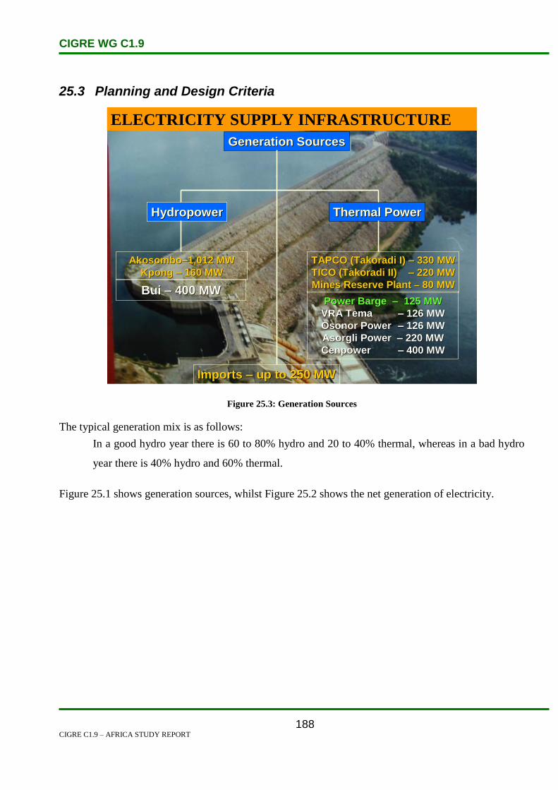
CIGRE WG C1.9
CIGRE C1.9 – AFRICA STUDY REPORT
188
25.3 Planning and Design Criteria
Generation SourcesGeneration Sources
HydropowerHydropower Thermal PowerThermal Power
AkosomboAkosombo––1,012 MW1,012 MW
Kpong Kpong –– 160 MW160 MWTAPCO (Takoradi I) TAPCO (Takoradi I) –– 330 MW330 MW
TICO (Takoradi II)TICO (Takoradi II) –– 220 MW220 MW
Mines Reserve Plant Mines Reserve Plant –– 80 MW80 MW
Imports Imports –– up to 250 MWup to 250 MW
ELECTRICITY SUPPLY INFRASTRUCTURE
Bui Bui –– 400 MW400 MWPower Barge Power Barge –– 125 MW125 MW
VRA VRA TemaTema –– 126 MW126 MW
OsonorOsonor PowerPower –– 126 MW126 MW
AsorgliAsorgli Power Power –– 220 MW220 MW
CenpowerCenpower –– 400 MW400 MW
Figure 25.3: Generation Sources
The typical generation mix is as follows:
In a good hydro year there is 60 to 80% hydro and 20 to 40% thermal, whereas in a bad hydro
year there is 40% hydro and 60% thermal.
Figure 25.1 shows generation sources, whilst Figure 25.2 shows the net generation of electricity.

CIGRE WG C1.9
CIGRE C1.9 – AFRICA STUDY REPORT
189
Figure 25.4: Electricity Nett Generation
In 2005, VRA total installed capacity was 1 730 MW made up of 1 180 MW from both Akosombo
hydro electric (1 020 MW) and Kpong’s (160 MW) and 550 MW from two thermal plants, TapCo
(330 MW) and TiCo (220 MW), all of which are located at Aboadze in the vicinity of Takoradi in
western Ghana. The TiCo plant was developed in partnership with CMS Energy which holds 90% of
the capital and the VRA 10%, with an option to repurchase the whole of the capital in favour of VRA.
Both thermal plants operate at present on Light Crude Oil (LCO) and Distillate Fuel Oil (DFO). They
are expected in the short term to be converted to gas when the WAGP project is commissioned in
2007.
It should be noted that as part of its rehabilitation, enhancement and modernization programme, VRA
has just augmented Akossombo hydro electric generation capacity from 912 MW to 1 020 MW, and a
similar project is under way at Kpong power plant.
VRA has, apart from these generation plants, a 30 MW capacity back-up diesel plant located at Tema.
TAG units mounted on barges (2 x 65.5 MW) at Effasu in western Ghana have been made available
for VRA by Ghana National Petroleum Company for exploitation and maintenance but, they are yet to
be connected to the network [2].

CIGRE WG C1.9
CIGRE C1.9 – AFRICA STUDY REPORT
190
Figure 25.5 shows Ghana’s installed capacity.
Figure 25.5: Ghana Installed Capacity
The domestic electric energy consumption is about 6 004 GWh. It is projected that the average local
load growth in Ghana over the next decade would be about 6% as a result of which local consumption
of electricity will reach 9 300 GWh by 2011. There is also potential for significant electricity exports
and supply to VALCO as the smelter resumed operations in early 2005 under a new management
structure.
Figure 25.3 shows the net electricity consumption.

CIGRE WG C1.9
CIGRE C1.9 – AFRICA STUDY REPORT
191
Figure 25.6: Nett Electricity Consumption
The firm capability of the hydro system of about 4 800 GWh represents about half of the projected
domestic consumption for the year 2010. This implies that at least 50% of Ghana’s electricity
requirement by the year 2010 would be provided from thermal sources. On the basis of the studies
carried out, the next generation addition is the completion of the expansion of the Takoradi power
station. This involves the addition of 110 MW steam unit in order to complete the combined cycle
arrangements for the TICO power plant. In the medium term, up to 600 MW of additional generating
capacity will be required by 2012. It is planned that this additional capacity will be met through the
establishment of thermal as well as hydro plants such as the Bui hydro project. An Indian company
formally approached the Ghanaian government to fund the construction of the Bui hydroelectric dam.
Currently, the Takoradi thermal power station is fuelled with light crude oil, which has appreciated
significantly on the world market (between US$70 and 80 in August 2006).
In order to secure a sustainable and cost-competitive fuel source, Ghana is involved in the West
African Gas Pipeline (WAGP) project for power generation. The WAGP project involves the
construction of a natural gas pipeline of about 600 km to supply natural gas from Nigeria to meet the
energy requirements of Ghana and other West African countries. The countries presently involved in
the project with Ghana are Nigeria, Benin and Togo. The WAGP project, which will provide a source
of clean fuel for VRA’s thermal generating facilities and other future thermal plants, is expected to
CIGRE WG C1.9
CIGRE C1.9 – AFRICA STUDY REPORT
192
deliver the natural gas fuel at relatively lower costs than the current light crude oil. It is expected that
the first gas will be delivered to the Takoradi plant by December 2006.
In addition, Ghana is involved in the development of the West African Power Pool (WAPP), aimed at
establishing a regional market for electricity trade. The WAPP is expected to allow the sharing of
available energy resources and increase the reliability of electricity supply in the West African region.
If the WAPP initiative succeeds, its benefits will yield several billions of dollars over the next couple
of decades [3].
25.4 Planning Approaches and Methods
As of December 2003, the existing transmission network system comprised 36 substations and
approximately 4 000 circuit km of 161 kV and 69 kV lines. This includes 129 km of double circuit
161 kV interconnection to Togo and Benin. There is also a single circuit, 220 km of 225 kV intertie
with Côte d’Ivoire’s network.
Most homes and businesses use 120 volt and 240 volt electric power, while industries often use much
higher voltages. Large commercial and industrial customers may by-pass the local distribution system,
receiving electricity at high voltage directly from the transmission system.
The electric power transmission system of Ghana is connected to its neighbours, Côte d’Ivoire on the
west by a 226 kV transmission line and Togo and Benin on the east by a 161 kV transmission line.
Ghana also supplies electric power to Burkina Faso in the north through a low voltage distribution
network. A high voltage transmission system between Ghana and Burkina Faso is being developed.
In 2002, Côte d’Ivoire exported 1 563 GWh of electricity (worth about US$77 million), of which 111
GWh went to Burkina Faso and another 233 GWh was transmitted across Ghana to Togo and Benin.
Also in 2002, Ghana exported an additional 170 GWh of electricity to Togo and Benin.
The following structure was adopted under the revamped system:
The Ministry of Energy is responsible for the broad policy direction of the electricity industry.
The Energy Commission is responsible for national planning, licensing of electricity utilities
and technical standards.
The Public Utilities Regulatory Commission has responsibility for economic regulation,
ensuring fair competition among utilities and monitoring quality of service.
Ghana generates most of its power from hydroelectric facilities, which do not cause emissions of
harmful elements into the atmosphere; but their large reservoirs have some impact on the environment
by flooding large areas, causing people to move, changing the ecology and causing silt formation [4],
[5].

CIGRE WG C1.9
CIGRE C1.9 – AFRICA STUDY REPORT
193
25.5 Specific Technical Issues
Before the commencement of the National Electrification Scheme (NES) in 1989, 4 175 communities
were identified as having a population of 500 or more. Of this number only 478 were supplied with
electricity. The NES was composed of District Capitals Electrification Project, National
Electrification Programme (NEP), Self Help Electrification Programme (SHEP) and System Re-
enforcement Programme. The SEP was introduced as a complementary activity to the NEP. It
accelerated grid connection for communities which felt that their proposed projects on the programme
of implementation were too far into the future, and reduced overall cost to government and also
introduced community ownership. The community must be within 20 km of an existing 11-kV/33-kV
network.
Figure 25.7: Communities Connected by NES
The number of towns connected before 1989 was 478 and the ones connected to date are 3 448. The
towns connected through SHEP are 1 900. The accessibility at commencement (1989) was 15% and
presently it is more than 60%. The polar photovoltaic project focused on the use of solar PV systems
in 48 rural communities in Northern Ghana [6], [7].
25.6 Financing Issues
Historically, financing of the operational activities of Ghana’s electric power industry has been from
government, either through multilateral or bilateral loan agreements.

CIGRE WG C1.9
CIGRE C1.9 – AFRICA STUDY REPORT
194
Table 25.2: Financial Performance of VRA, 1997–2002 (in ¢Billion)
Year 1997 1998 1999 2000 2001 2002
Operating
profit/(Loss)
61.2 18.7 79.2 (257.9) (220.0) (582.2)
Net Profit/(Loss) (58.6) (105.2) (283.2) (983.3) (329.7) (1 269.1)
Table 25.3: Financial Performance of ECG, 1997–2002 (in ¢Billion)
Year 1997 1998 1999 2000 2001 2002
Operating
profit/(Loss)
(33.9) 6.0 17.3 (13.6) 152.9 (85.3)
Nett
Profit/(Loss)
(80.9) (27.5) (79.2) (394.0) 110.1 (380.5)
Since most of the electricity is generated from hydro facilities that were built several decades ago, the
cost of generation was rather low (about 2 to 2.5 US cents per kWh). However, as demand grew and
VRA experienced difficulty supplying electricity during years of low rainfall, new thermal plants were
built in the late 1990s. These plants have generating costs ranging from 4.5 to 8 US cents per kWh and
sometimes higher, depending on the cost of imported fuels such as light crude oil, raising the average
cost of generation from about 2 US cents per kWh in the mid-1990s to about 6 US cents in 2002.
However, tariffs to end-users have not always reflected these costs due to government’s subsidized
tariff policy. Electricity supply is divided into bulk electricity (transmission level) and final electricity
(distribution level). The average bulk electricity price was below 4 US cents per kWh in the early
1990s until 1998, when it went up to between 4 to 4.5 US cents per kWh, below the cost of generation.
After its establishment in 1997, the PURC started setting electricity tariffs, in consultation with key
stakeholders comprising the generators, distributors and representatives of major consumers. The
PURC developed a transition plan to trigger a gradual adjustment to economic cost recovery by 2003.
The automatic price adjustment formula of the Transition Plan was implemented once in 2003 and
twice in 2004, with the latest adjustment in 2004 affecting only the bulk supply tariff (BST) and the
distribution service charge (DSC). The sum of the BST and the DSC is the end user tariff (EUT)
charged by the distribution companies. The addition of thermal generation has pushed up the EUT to
about 8.2 US cents per kWh, with a BST of about 4.8 US cents (including a ‘postage stamp’
transmission charge of about 0.9 US cents) and a DSC of about 3.4 US cents.
There are different tariffs for industrial, commercial (non-residential) and residential customers. The
tariff for residential customers has a lifeline tariff for low consumption, which was set at 100 kWh per
month maximum in 1989/90 but was downgraded to 50 kWh per month maximum by 2000, which is
still high compared to some neighbouring countries (for example, 20 kWh for Benin and 40 kWh in
Togo). The lifeline tariff is about US$1.50 per month. The government of Ghana subsidizes the

CIGRE WG C1.9
CIGRE C1.9 – AFRICA STUDY REPORT
195
lifeline consumers to the tune of about US$1 per month but it has been unable to make regular and
timely remittances to the utilities. The total subsidies owed by the government to the distribution
utilities by the end of 2003 ranged from US$400 000 to US$1.4 million.
The average tariff for final electricity was below 5 US cents per kWh until 1998 when it shot up to
between 5.2 to 8.2 US cents per kWh. However, at a level above 8 US cents per unit, though relatively
low compared to some neighbouring countries, the tariff is not attractive for high level commercial and
industrial usage. At the same time, industrial customers subside residential consumers. These policies
are hampering the development of an industrial base in Ghana that can compete in regional and global
markets, and fuel economic growth.
There are a number of other challenges in fixing the distortions in electricity tariffs. First, utilities
need to improve their operational efficiencies so that they can be financially sound while lowering
tariffs for consumers of electricity. A second and related challenge concerns the average tariff
collection efficiency, which has ranged from 75% to 85%. The PURC has a benchmark of 95%.
Although utilities are called upon to improve their customer relations and service quality, consumers
need to act responsibly as well. Otherwise, the electricity system cannot be expanded reliably to meet
the growing demand [3].
The National Electrification project is sponsored by JICA, DANIDA, World Bank, Dutch Government
(ORET), SIDA, FINIDA, NDF and GEF through grants and soft loans. The Self Help Electrification
Project (SHEP) is sponsored by Indian Ex-Im Bank, US Ex-Im Bank, SIDA, FINNIDA, South African
Government and Chinese Ex-Im Bank through soft loans [6].
The two utility companies of Ghana and Togo are providing 2.1 million Euros for the Kajebi-Badou
interconnection project while the European Union (EU) is providing the balance of 1.5 million Euros.
The EU is providing another 13.2 million Euros in grant to ECOWAS for two other cross-border
medium voltage projects along the Ghana-Burkina Faso and the Côte d’Ivoire-Liberia borders.
Funding is also obtained under the EU–ACP Energy Facility [5].
25.7 Human Resource Issues
Table 25.5 illustrates the distribution of staff by categories for the years 2006 and 2007 for ECG. The
ratio of female to male staff at the end of 2007 was 1:4.1. 210 new appointments were made whilst 162
left the services of ECG in 2007 [8].

CIGRE WG C1.9
CIGRE C1.9 – AFRICA STUDY REPORT
196
Table 25.4: Distribution of Staff by Category
CATEGORY 2007 2006
Directors 8 8
Other Management Staff 157 156
Electrical Engineers 112 70
Technician Engineers 476 472
Works Superintendents 45 55
Human Resource Officers 32 34
Accounts and Audit Officers 213 223
Other Senior Staff 253 257
Junior (technical) 1 466 1 462
Junior (non technical) 1 684 1 634
Gen. Workers and Security staff 533 450
Total 4 979 4 931
One of the major problems for underdevelopment in Ghana can be attributed to the inadequate of
human resources in the country and other resources. This is because of the inadequate practical
training given to both students and workers of science, technical and other aspect of studies. Students
in both the tertiary and high schools lack the practical aspect of what they study. There Ghanaian
students and workers that theoretically know what their career is about but practically they fumble and
struggle. This therefore causes the country to lack the human resource to move the country from a
technologically-stagnant country to technologically-dynamic country. What can be done to enhance
this part of the human resource is by exposing both the students and workers to practical
training in their field and not only the theoretical aspect. [9]
The low human resource in the country is due to the financial status of the country, i.e. the ability of
the country to financially manage the sources that usually make up the human resources, such sources
include feasibility studies. There are citizens available to take on to the management of their natural
resources but the finances to help the people or the citizens are the problem. There are those who are
ready and are also educated to the tertiary level or over. In order to solve the problem in the country,
there is the need for the government to help the individual and for workers to help further their
education. The available human resource personnel in the country should take time to make sure that
the implementation of relevant policies, processes or standards that will bring development to the
country is done with patriotism. [9]
25.8 References
1. http://www.geni.org/globalenergy/library/national_energy_grid/ghana/index.shtml
2. https://www.cia.gov/library/publications/the-world-factbook/geos/gh.html

CIGRE WG C1.9
CIGRE C1.9 – AFRICA STUDY REPORT
197
3. Http://Www.Esi-Africa.Com/Node/7765
4. Guide to Electric Power in Ghana; First Edition; Resource Centre for Energy Economics
and Regulation Institute of Statistical, Social and Economic Research University of Ghana,
Legon; July 2005
5. http://ec.europa.eu/europeaid/where/acp/documents/com_interconnectivity_energy_en.pdf
6. http://www.club-er.org/upload/DOCAT306.ppt
7. http://www.e-parl.net/hearings/31/82/Akosombo_EParliament.ppt
8. Electricity Company of Ghana LTD.; Annual Report and Audited Accounts 2007.
9. http://www.ghanaweb.com/GhanaHomePage/NewsArchive/artikel.php?ID=197065
CIGRE WG C1.9
CIGRE C1.9 – AFRICA STUDY REPORT
198
26. Guinea
26.1 Electricity Industry Structure
The Republic of Equatorial Guinea is a country located in Central Africa with an area of 28 000 km2.
It is one of the smallest countries on the African continent, having a population estimated at 0.5
million. It comprises of two parts, Rio Muni (a continental region) including several offshore islands
like Corisco, Elobey Grande and Elobey Chico; and an insular region containing Annobon and Boiko
island.
Guinea’s electricity sector is owned and operated by Sociedad de Electricidad de Guinea Ecuatorial
(SEGESA), in which the Government holds a 62% stake and a Spanish company, Infinsa, the
remaining 38%. Electricity tariffs are approved by the government. Electricite de Guinea (EDG) is
the state owned utility responsible for generation, transmission and distribution of electricity in
Guinea. However, private producers (mainly mining companies) also play an important role in
generating electricity, and currently supply of about 48% of total electricity demand. [1][2].
Figure 26.1 shows the map of the transmission network of Guinea [3].

CIGRE WG C1.9
CIGRE C1.9 – AFRICA STUDY REPORT
199
Figure 26.1: Guinea Transmission Network [3]
Guinea’s 110 kV transmission n system connects the hydro plants, Garafiri to Conakry, Kindia, Linsan
and Mamou. A 30 kV line supplies the areas of Dalaba, Pita and Labe.
Guinea has no indigenous sources of oil, natural gas or coal. It consumes and imports 9 000 barrels of
oil a day. There is no oil refinery and as a result, all refined products such as gasoline and jet fuel must
be imported. Of the installed electric capacity, 57% is hydropower and the remainder is thermal (oil
and diesel). Guinea has great hydropower potential that could make it a major exporter of electricity.
Its estimated potential is 6 100 MW but its installed hydropower capacity is 138 MW. In January 2008,
China agreed to fund the $1 bn Souapiti hydropower dam project in return for rights to mine bauxite,
the aluminum ore of which Guinea is the world's largest exporter. It will generate 750 MW of
electricity. Along with Gambia, Guinea Bissau and Senegal, Guinea is a member of the Gambia River
Basin Development Organization. There are plans to build hydropower plants on the Gambia River in
Senegal and at Kaleta in Guinea to provide energy for the region and to construct electrical
transmission lines between the 4 nations. The projects will be designed, financed, constructed and
operated as a public-private partnership. Construction has not yet begun because of lack of financing.

CIGRE WG C1.9
CIGRE C1.9 – AFRICA STUDY REPORT
200
The state owned Electricite De Guinee (EDG) is the producer, distributor and transmitter of electricity.
It is in poor financial condition. In 2006, it could only provide about 35% of electrical demand. The
electrification rate is 19%. There are frequent power outages and shortages, especially in rural areas
[7].
26.2 Load and Energy Forecasting
The mining sector is very important in Guinea, accounting for around 40% of total electricity demand,
and thus greatly influences any forecast of electricity demand. Linked with the mining industry are
possible processing plants, such as the proposed construction of an alumina production plant and
aluminum smelter, which would consume over 26 000 GWh per year. The Guinea government
expects this development to be operational from 2014, and it would account for 65% of the mining
sector demand, and for 42% of the total electricity demand.
Table 26.1 shows the Guinea peak demand forecast:
Table 26.1: Guinea Peak Demand Forecast [1]
2003
MW
2007
MW
2011
MW
2015
MW
2020
MW
Forecast, excluding mining 143 186 248 341 453
Mining sector, excluding smelter 4 18 148 234 251
Sub-total, excluding smelter 147 204 396 575 704
Proposed aluminium smelter - - - 375 394
Total 147 204 396 949 1098
Peak demand for the mining sector reflects the continuing expansion of the interconnected network in
Guinea, with 126 MW of new demand being connected in 2009, a further 75 MW in 2013, and the
proposed aluminum smelter, 371 MW in 2014.
26.3 Planning and Design Criteria
Electricite de Guinee (EDG) generates just over half the electricity in Guinea (52% in year 2000). The
remainder is generated by private producers (mining companies), which also supply local
communities. Private generation was 557 GWh in 2000, from about 100 MW of installed capacity.
This compares with the 595 GWh generated by public utilities from 309 MW of installed capacity.
The total for guinea in 2000 was 1152 GWh. In 2004, private generation capacity increased by 20
MW (two units of 10 MW).

CIGRE WG C1.9
CIGRE C1.9 – AFRICA STUDY REPORT
201
The structure of the existing and future installed capacity of the Guinea electric power system (EDG)
is illustrated in Table 26.2.
Table 26.2: Future and Existing Installed Capacity of the Guinea Electric Power System [1]
Existing Generation Installed Capacity
Thermal Power Plants 67.4 MW
Hydro Power Plants 120.4 MW
Total 187.8 MW
Future Generation before 2011
Thermal Power Plants in 2004 32.4 MW
Hydro Power Plants in 2008 105 MW
Hydro Power Plants in 2009 120 MW
Total 257.4 MW
Current plans for generation foresee the development of hydro plants at Fomi (90 MW, 374 GWh/yr)
in the medium term, and at Sambangalou (120 MW, 400 GWh/yr) and Kaleta (105 MW, 900 GWh/yr)
in the frame work of OMVG development. The OMVG 225 kV transmission network will
interconnect the countries of Guinea, Guinea-Bissau, Gambia and Senegal. Further transmission links
to Mali and Côte d’Ivoire would be included with Fomi. A link from Linsan, on the HV transmission
network in Guinea, to Bumbuna in Siera Leone is also anticipated at some time in the future.
26.4 Planning Approaches and Methods
Guinea is a mountainous land and has heavy rainfall which results in the country having substantial
hydro resources. The total hydro resource which could be economically developed is about 6 000 MW
at 129 sites ranging in size from 3 MW to 750 MW [1]. These would produce on average around
26 000 GWh per year (19 000 GWh guaranteed). The Fomi project at one of the 129 sites will not be
developed as part of OMVG. It is a multi-purpose project and its aim is:
To generate electricity (3 x 30 MW Kaplan turbines, making 90 MW; average annual energy
374 GWh, guaranteed 267 GWh).
To irrigate 80 000 hectares in Guinea and Mali.
To develop fishing potential in the 500 km2 lake that would be created by the dam, and along
the banks of the river Niger.
To improve navigation along the river Niger between Bamako and Kankan and between
Bamako, Siguiri and Kouroussa.

CIGRE WG C1.9
CIGRE C1.9 – AFRICA STUDY REPORT
202
Another interesting point is that its location in Haute Guinee would also provide an opportunity to
build transmission links with: OMVG; Man, Côte d’Ivoire; Bamako, and Mali. It would also allow the
extension of the Guinea transmission network into Haute Guinee and into Guinee-Forestiere.
The feasibility study carried out by SNC-Lavalin in 1999 concluded that it would cost US$ 300 million
and produce energy at 7 to 7.7c/kWh (11.3c/kWh, including the transmission network). The benefits
from agriculture and fishing were also taken into account.
26.5 Specific Technical Issues
EDG’s electricity transmission networks comprise approximately 130 km of high tension lines. The
network on the mainland serves the suburban area of Bata, while the second oldest distribution system
on Bioko Island, connects Malabo to the port of Luba. SEGESA’s electricity generating capacity is
now more than enough to meet demand on both the continent and the island of Bioko, but its power
supply is unreliable due to aging equipment and consumers often experience prolonged blackouts. The
government has plans to expand this grid by 2010.
Small diesel and gasoline-powered generators are widely used as a back-up source of power supply.
The Guinean government has attempted to privatize SEGESA in an effort to increase competition and
efficiency in the electricity sector; however foreign companies have shown little interest in the state
owned company [4, 5].
SEGESA’s power supply is unreliable as a result of aging equipment and poor management. Illegal
connections and generous subsidies to low-end users contibute to SEGESA’s financial dificulties,
preventing the necessary upgrading of the grid.
Generating capacity is made up of thermal generation (80%) and hydroelectric generation (20%). The
extension of the gas-fired power plant in Punta Europa, near the capital Malabo, was finished in 2004,
and has four turbines that can generate 28 MW. An additional 4 MW of generation capacity bas been
built at the methanol complex on Boiko Island. The mainland region is supplied by thermal plants,
which are connected to a network which is independent from the one in Boiko Island. The government
started a mjor rehabilitation and expansion of the electricity grid in Boiko in 2007, but few areas
outside the main towns receive a regular supply of electricity[2].
26.6 Financing Issues
As of September 2007, the World Bank in Guinea supports a portfolio of eleven projects (two are
regional) which total about US$216 million. Projects are concentrated in the following areas:
community development,
rural infrastructure,

CIGRE WG C1.9
CIGRE C1.9 – AFRICA STUDY REPORT
203
education,
transport,
electricity,
health/HIV/AIDS, and
rural electrification.
The World Bank has approved the second phase of both the Village Community Support Project and
the Third Urban Project. As the macro-economic situation and governance improve, the lending
options will be enhanced. One of the eleven projects that the World Bank supports is the Efficiency
Improvement Project.
The Electricity Sector Efficiency Improvement Project of Guinea seeks to improve the electricity
sector’s commercial and operational efficiency. These results will be achieved through critical
investment support and capacity building, affecting the financial viability of the sector and quality of
service delivery. The project contributes to the reduction of carbon dioxide (CO2) emissions by
addressing the large inefficiencies in the distribution sector and reducing energy losses.
The project will support investments that aim at improving:
(i) Distribution networks and generation capacity for reliability of supply,
(ii) Commercial character, and
(iii) Customer interface of the electricity sector.
Implementation of the Project will be structured along the following three components:
Distribution efficiency improvement:
The efficiency improvement programme referred to as the Commercial Re-orientation of the
Electricity Sector Toolkit (CREST), comprising a set of best practice interventions, is designed
and implemented by the Guinea Electricity Company (EDG) with active support from the
World Bank team. The programme re-engineers core business processes (with a pronounced
focus on the retail metering, billing and collection (MBC) functions), and deploys innovative
technology solutions in order to improve service delivery to reduce technical and commercial
losses.
Rehabilitation (Repair and Maintenance) of Critical Generation:
Investment support would be provided to EDG, through this project to improve the reliability
and efficiency of the existing Garafiri hydroelectric plant and the Tombo thermal power plant.
This will be in the form of assistance for critically required equipment and spare parts and
technical assistance for operations. This component will also involve technical studies to better

CIGRE WG C1.9
CIGRE C1.9 – AFRICA STUDY REPORT
204
analyse and understand the current condition of the generation facilities; and to identify
required upgrades to improve generation capacity.
Institutional Strengthening through Technical Assistance:
A strong institutional base is fundamental to the sustained financial success of the power sector
in Guinea. There is a clear and urgent need to develop a robust and modern technical, financial
and accounting infrastructure base to support the efforts of EDG to improve its managerial,
financial and operational performance. Further, opportunities for efficiency enhancements
from private sector partnerships and demand side management (DSM) will be identified and
explored [6].
26.7 Human Resources
No discussion on human resource issues was presented.
26.8 References
1. Final Report ‘West Africa Regional Transmission Stability Study’. Volume 2: Master Plan.
2. http://fic.wharton.upenn.edu/fic/africa/Equatorial%20Guinea%20_2_.pdf
3. http://www.geni.org/globalenergy/library/national_energy_grid/guinea/guineanationallectri
citygrid.shtm
4. http://www.eia.doe.gov/emeu/cabs/Equatorial Guinea/Full.html
5. http://www.state.gov/r/pa/ei/bgn/7221.htm
6. http://web.worldbank.org/external/projects
7. http://www.estandardsforum.org

CIGRE WG C1.9
CIGRE C1.9 – AFRICA STUDY REPORT
205
27. Guinea-Bissau
27.1 Electricity Industry Structure
The Republic of Guinea-Bissau is situated between Senegal and Guinea on the West African mainland
with 30 islands off the coast. The country covers an area of 36 125 km2 and has a population of
1.6 million. The economy is highly dominated by the agricultural sector in which cashew nuts
represent over 85% of export earnings. Guinea Bissau is classified 172nd
out of 177 countries featured
in the United Nations Human Development Index of 2004, with 88% of the population living on less
than US$1 a day [2, 3].
The electric system of Guinea-Bissau is managed by the Electricity and Water Company of Guinea-
Bissau (Electricidade e Aguas de Guinea-Bissau, EAGB). EAGB is owned by the national government
and is responsible for 90% of power production, with the remaining 10% originating from small,
independent power producers.
The total installed electricity capacity in Guinea-Bissau is about 21 MW (2008).Conventional thermal
generation makes up 100% of the total installed capacity.Electricity and water production and
distribution in Guinea-Bissau have virtually collapsed since 2000. Only a small proportion of the
population has access to public electricity and water supply, primarily in the capital Bissau, and only
part of the time. The country’s entire public power system is operating on 5.5MW of generation
capacity, 25% of what it had been before the 1998-99 internal conflict and equivalent to the capacity
needed to supply less than 2000 people in the US.
Due to failure of public electricity supply, there is an estimated 20 megawatts of private capacity
installed by large consumers like embassies, international organizations, hotels and other institutions,
and around 1,000 small generators used in the residential sector. “This is costly to the fragile economy
of Guinea-Bissau in terms of competitiveness and has a negative environmental impact as small diesel
generators are more costly and less energy efficient than larger utility-run plants”, Cherif concluded
The Electricity and Water Company of Guinea-Bissau (EAGB) is a public enterprise and is responsible
for both water and electricity supply and distribution in the city of Bissau. EAGB’s Board of Directors
is composed of representatives of the Ministry of Finance, the Ministry of Rural Development, Natural
Resources and Environment (MDRRNA), and representatives of employees of EAGB, the Chamber of
Commerce, the Municipality of Bissau, and the Director General of EAGB. The MDRRNA is
responsible for water and electricity in the secondary cities [3].
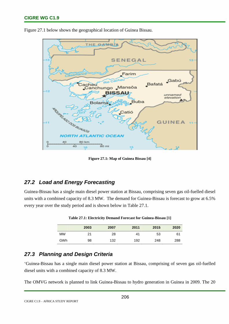
CIGRE WG C1.9
CIGRE C1.9 – AFRICA STUDY REPORT
206
Figure 27.1 below shows the geographical location of Guinea Bissau.
Figure 27.1: Map of Guinea Bissau [4]
27.2 Load and Energy Forecasting
Guinea-Bissau has a single main diesel power station at Bissau, comprising seven gas oil-fuelled diesel
units with a combined capacity of 8.3 MW. The demand for Guinea-Bissau is forecast to grow at 6.5%
every year over the study period and is shown below in Table 27.1.
Table 27.1: Electricity Demand Forecast for Guinea-Bissau [1]
2003 2007 2011 2015 2020
MW 21 28 41 53 61
GWh 98 132 192 248 288
27.3 Planning and Design Criteria
‘Guinea-Bissau has a single main diesel power station at Bissau, comprising of seven gas oil-fuelled
diesel units with a combined capacity of 8.3 MW.
The OMVG network is planned to link Guinea-Bissau to hydro generation in Guinea in 2009. The 20

CIGRE WG C1.9
CIGRE C1.9 – AFRICA STUDY REPORT
207
MW Saltinho hydro project on the river Corubal could be developed as part of the OMVG but, at $US
82 million (equivalent to $US 4100 per kW, or approximately 13c per kWh), it is unlikely to be
developed in the near future.’ [10]
27.4 Planning Approaches and Methods
Guinea-Bissau has one of the lowest electrification rates in Africa. The country is completely
dependent on petroleum products, despite its own high energy potential, especially in hydroelectric
power. Construction of a dam at Saltinho could eventually supply the whole country and provide
excess electricity for export, but little progress has been made [7].
In October 2000, the 14 members of the Economic Community of West African States (ECOWAS), of
which Guinea-Bissau is a member, signed an agreement to launch a project to boost power supply in
the region of West Africa. The West African Power Pool (WAPP) agreement reaffirmed the decision
to develop energy production facilities and to interconnect their respective electricity grids. Guinea-
Bissau, along with countries such as Guinea, Liberia, Mali, Senegal, Gambia and Cape Verde, will be
actively involved in the WAPP agreement. Under the agreement, WAPP is will harmonize the
regulatory framework that governs the electricity sector in each member country [5].
Guinea-Bissau has an average solar radiation of 4.5 to 5.5 kWh/m2/day, over an average of 8 hours per
day (3,000 h of insolation per year). In spite of this promising potential, up to now only 450 kW of
photovoltaic (PV) installations are installed, used for communication networks, water pumping stations
and house lighting. The government plans to significantly increase the utilization of PV in order to
cover up to 2 % of overall energy consumption by 2015.
The average wind speed is estimated at 2.5 to 7 m/s along the coast and on some of the islands. Even
though there is a very promising potential, there are no plans for utilization of wind power in Guinea-
Bissau so far.
The available hydropower potential of Guinea-Bissau is estimated at about 184 MW from the rivers
Corubal and Geba. Even though there is a very promising potential available, up to now there is no
significant use of hydropower in Guinea-Bissau.
27.5 Specific Technical Issues
Electricity production capacity is low and is only from thermal sources. There are strong regional
differences in electricity supply, and the poor performance and ageing of the electricity infrastructure
are resulting in high electricity costs and frequent power cuts with knock-on effects on businesses and

CIGRE WG C1.9
CIGRE C1.9 – AFRICA STUDY REPORT
208
economic and social development. Technical and non-technical losses contribute significantly to the
financial problems of the sector. Repairs to the existing plant and transformers, and installation of
meters are necessary to curb these losses
Electrification covers only 12% of the country and electricity service costs are five times higher than in
Senegal. The numerous shortages caused by the Public Company of Water and Electricity (EAGB)
have forced companies to install electric generators. Guinea Bissau is endowed with several renewable
energy resources; and in particular it receives a large amount of solar energy [10].
27.6 Financing Issues
Guinea-Bissau has an inadequate institutional, legal and regulatory framework. The Government
formulates water and energy policies following recommendations from the Board of EAGB, and is
responsible for regulation, and determines and approves tariffs. There is no clear separation of
responsibilities and the laws establishing the duties of the main stakeholders are not enforced. The
main issue facing the water and power sectors in Guinea-Bissau is the lack of corporate autonomy of
EAGB, its non-commercial organization and poor performance.
EAGB is the only institution in the country which currently has the technical capacity to deliver water
and energy to the population. However, the performance-based management contract under which the
EAGB functioned, proved to be inadequate and has led to deteriorating services and a financial crisis
for the company. There were four main complaints raised by the private sector [3]:
the lack of Government commitment to reforms and tariff adjustment,
the absence of financing to carry out investment (an intended investment by the European
Investment Bank of US$8 million in the energy sector was canceled due to the non-observance
by the Government of its financial obligations),
lack of support in commercial litigations, and
Government arrears in paying its own water and electricity bill.
27.7 Human Resources
On the 15 June 2006, the World Bank Board of Executive Directors approved an International
Development Association (IDA) credit of US$15 million for both Urban Water Supply and Medium-
Term Supply of Electricity in Guinea Bissau [3] [9]. Given the unsustainable situation that EAGB
faces in terms of providing safe and affordable water and ensuring a reliable supply of electricity to the
population, the overall development objectives are:
to alleviate the effects of poverty (through job creation) and improve health by increasing
access to safe and affordable water and sanitation,
CIGRE WG C1.9
CIGRE C1.9 – AFRICA STUDY REPORT
209
to ensure a reliable and affordable supply of water and electricity for economic growth,
to ensure sustainability by improving water pricing and electricity tariffs for cost recovery and
developing the Government’s regulatory and planning capacity in these sectors,
to encourage competition and private sector participation by reducing the government’s
involvement in these sectors and introducing, under open competitive bidding, a
lease/concession contract with private management, and
to ensure efficient consumer and producer behavior by introducing commercial pricing under
incentive regulation.
Through the project, electricity generation is expected to increase by 15 MW while the electricity bill
payments are expected to rise from 40% to 80%. The capacity of the distribution network will grow
from 11 500 MWh per year to 65 700 MWh with power distribution losses falling to below 10%.
27.8 References
1. Final Report ‘West Africa Regional Transmission Stability Study’. Volume 2: Master Plan.
2. http://www.infoder.org/en/Document.408.pdf
3. Document of the World Bank; Staff Appraisal Report, Republic of Guinea-Bissau Water
and Energy Project; Report No: 17325-GUB, May 18 1998
4. http://www.infodev.org/en/Document.408.pdf
5. http://www.mbendi.com/indy/powr/af/gb/p0005.htm
6. http://www-wds.worlbank.org/external/default/main
7. Http://www.nationsenclyclopedia.com/economies/Africa/Guinea-Bissau-Infrastructure-
Power-and Communication.html
8. http://www.estandardsforum.org/secure_content/country_profiles/cp_82.pdf
9. http://www.reliefweb.int/rw/rwb.nsf/db900SID/KHII-6QT35A
10. http://www.icrgq.com/icregq-08/295-boccalletti.pdf
11. http://www.ecowapp.org/Volume%202%20Master%20Plan%20-%20Final.pdf

CIGRE WG C1.9
CIGRE C1.9 – AFRICA STUDY REPORT
210
28. Kenya
28.1 Electricity Industry Structure
Kenya’s population is estimated at 31.3 million (2002) from 16.6 million in 1980. The population is
expected to grow to 37.5 million by 2015, which is an annual increase of 1.4% per year.
The majority of the population resides in the rural areas.
Undeveloped hydroelectric power of economic significance is estimated at 1 558 MW.
About 15% of the population has access to electricity.
Kenya’s energy is dominated by three primary factors, namely:
Predominant reliance on dwindling biomass energy resources to meet the energy needs of the
rural households, which account for 68 % of the total national energy consumption.
Imported petroleum to meet the modern economic sector needs that contributes 22%.
Electricity power that accounts for 9%.
The ESI of Kenya is under three main power generation companies, and one integrated transmission,
distribution and sales company, namely:
The government-owned Kenya Electricity Generating Company (KenGen) which owns most of
the generation facilities and supplies about 85% of electricity demand.
Several IPPs which contribute 12% of demand.
Imported power, contracted with the Uganda Electricity Transmission Company (UETCL),
which meet 3% of Kenya’s demand.
85%
3%12% 0%
KenGen Import IPPs REP
Figure 28.1: Electricity Supply by Source in Kenya.

CIGRE WG C1.9
CIGRE C1.9 – AFRICA STUDY REPORT
211
The Kenya Power and Lighting Company Limited (KPLC) is a monopoly utility responsible for power
transmission and distribution. The Energy Regulatory Commission (ERC) was established in terms of
the Energy Act, 2006, and supercedes the previous Electricity Regulatory Board. The ERC is
responsible for:
Performing all the regulatory functions,
setting, reviewing and approving tariffs,
investigating tariff structures,
enforcing environmental and safety regulations,
investigating complaints made by consumers,
ensuring that there is genuine competition where this is needed, and
making recommendations to the Ministry of Energy in the granting and revocation of
generation and distribution licenses.
The Ministry of Energy oversees all the activities within the power sector.
Figure 28.2: Electricity Supply Industry Structure in Kenya
In 1996, the Government of Kenya (GoK) officially liberalized power generation as part of a power
sector reform effort. From that time onward, it became government policy that all bids for generation
facilities would be put out for competition, open to both public and private firms, i.e. the national
generator would receive no preferential treatment.
The Energy Act of 2006 liberalized the sector further. IPPs are permitted to build generation and/or
transmission capacity and to sell power directly to customers.

CIGRE WG C1.9
CIGRE C1.9 – AFRICA STUDY REPORT
212
28.2 Load and Energy Forecasting
In 2004/05 Kenya Electricity sales grew by 7% from 3 940 GWh the previous year to 4 215 GWh,
mainly due to improved economic performance whereby the real gross domestic product (GDP) grew
from 2.6% in 2003 to 4.3% in 2004/05.
Kenya load forecast is based on econometric models and different categories of customers are modeled
separately. The main independent variables are:
Sectoral GDP growth rates, and
Moving average electricity tariffs.
There are four forecast models employed, namely:
1. Domestic forecast model. Relates sales to non-agricultural GDP and moving average tariff
for domestic customers.
2. Commercial/Industrial forecast model. Relates sales to manufacturing sector GDP, services
sector GDP, and moving average commercial/industrial tariffs.
3. Off-peak forecast model. Relates sales to moving average off-peak tariff.
4. Rural Electrification (RE) forecast model. Cumulative investment in RE assets and moving
average tariff for domestic customers.
Giving room for uncertainties in load forecasting, a three-scenario sensitivity analysis is developed.
Low.
Reference.
High Forecast.
Figure 28.3: GDP and Sales Annual Growth in Kenya

CIGRE WG C1.9
CIGRE C1.9 – AFRICA STUDY REPORT
213
-
1,000
2,000
3,000
4,000
5,000
6,000
7,000
2004/2005 2008/2009 2012/2013 2016/2017 2020/2021 2024/2025 2028/2029
Years
MW
Low Forecast Reference Forecast High Forecast
Figure 28.4: Sensitivity Analysis of Load Forecasting in Kenya
Figure 28.5: Daily Electricity Demand Pattern in Kenya
28.3 Planning and Design Criteria
Generation planning – the probabilistic approach is used with loss of load expectation (LOLE) of 10
days and EUE of 0.1% per year.
The desired reserve margin for average hydrology is 15%, and 10% for dry hydrology.
Transmission planning and design includes transmission voltages of 132 kV and 220 kV. Future
design will include 330 kV to 440 kV transmission lines. The N-1 criterion is employed in
transmission planning.

CIGRE WG C1.9
CIGRE C1.9 – AFRICA STUDY REPORT
214
Operational Considerations – through the application of standard designs for ease of future operation
& maintenance, and also to reduce existing operational risks.
Safety Considerations – adherence to statutory requirements for public safety and that of operating &
maintenance personnel.
Reliability – the transmission system should be capable of meeting defined reliability standards.
Environmental – evaluation of environmental impact.
Economics – evaluation of life cycle costs.
Performance – achieving the defined technical requirements.
28.4 Planning Approaches and Methods
Roles of interconnections:
Planning approach to sharing of energy resources:
o Preparation of East African Regional Master Plan for Kenya, Uganda and Tanzania.
o Regional interconnection studies through the Nile Equatorial Lakes Subsidiary Action
Program Coordination Unit (NELSAP-CU) under the Nile Basin Initiative.
o Bi-lateral arrangements e.g. between Kenya and Ethiopia.
Co-ordination of interconnection planning:
o Preparation of East African Regional Master Plan for Kenya, Uganda and Tanzania.
o Regional interconnection studies through the Nile Equatorial Lakes Subsidiary Action
Program Coordination Unit (NELSAP-CU) under the Nile Basin Initiative.
o Bilateral arrangements e.g. between Kenya and Ethiopia.
Environmental Issues:
o Adherence to environmental requirements of each country.
List of environmental issues:
Vegetation growth, in particular tree branches in close proximity to power lines,
has a notable effect on power supply quality especially affecting low voltage
customers. Contact between tree branches and overhead lines are the major
cause of power supply interruptions to customer premises.
Falling trees aggravated by thunderstorms.

CIGRE WG C1.9
CIGRE C1.9 – AFRICA STUDY REPORT
215
Changes in ambient temperatures, power transfer angles and inductive load
component can affect the efficiency of transmission network operations.
Human settlement, including relocation and resettlement.
Carbon emissions.
Meeting environmental regulations in planning:
o EIA studies whose terms of reference are approved by the National Environment
Management Authority (NEMA) have to be undertaken, and clearance by NEMA
obtained before a project can be implemented.
Figure 28.6: Kenya Electrical Power Network

CIGRE WG C1.9
CIGRE C1.9 – AFRICA STUDY REPORT
216
Figure 28.7: Kenya Electrical Power Generation

CIGRE WG C1.9
CIGRE C1.9 – AFRICA STUDY REPORT
217
Figure 28.8: Regional Interconnection
28.5 Specific Technical Issues
Containment of short-circuit levels:
Radial operation of the sub-transmission system.
Fault level within 25 kA.
Opening bus section couplers.

CIGRE WG C1.9
CIGRE C1.9 – AFRICA STUDY REPORT
218
Application of new technologies:
The country is installing a new SCADA/EMS system for the national power control system.
Customer bills can be queried through the use of mobile phones.
Payment of electricity bills by the use of electronic systems is at the preparation stage.
A pilot project on prepaid meters is currently under discussion for implementation.
28.6 Financing Issues
The financing source of the Kenyan electricity infrastructure is from donors and company generated
revenue. The Companies also seek commercial funds such as bonds and rights issues.
Private investors have to make their own funding arrangements.
Electricity project investment is guided by a 5-year business plan, however contracts signed with IPPs
are long term, up to 20 years.
The following are the roles of lending agencies and their requirements:
Multilateral lending agencies participate in studies and project financing.
Lending conditions are usually negotiated.
Seed contribution is a requirement by most lenders.
Kenya’s power sector reform has contributed to private investment in power projects.
28.7 Human Resources
No discussion on human resource issues was presented.

CIGRE WG C1.9
CIGRE C1.9 – AFRICA STUDY REPORT
219
29. Lesotho
29.1 Electricity Industry Structure
Lesotho is a landlocked independent republic situated within the borders of South Africa. It forms part
of the Southern African Region and is a member of the Southern African Power Pool (SAPP).
Governance of the electricity supply industry (ESI) is the responsibility of the Department of Energy
(DoE) located in the Ministry of Natural Resources (MNR).
Lesotho Electricity Authority (LEA) is responsible for regulating the ESI sector. The other two
institutions principally involved are;
Lesotho Electricity Company (LEC), and
Lesotho Highlands Development Authority (LHDA).
LEC is a statutory corporation, established under the Electricity Act of 1969, responsible for all
distribution to end-users. LEC owns and operates the main 132 kV transmission system and also owns
and operates four mini hydro power stations, of which only one is connected to LEC’s grid.
LHDA was established in 1986 as an autonomous statutory body, and is the implementing agency for
the water delivery and hydro-power projects in Lesotho linked to the Lesotho Highlands Water Project
(LHWP). LHDA owns and operates the 72 MW Muela hydro power station.
Figure 29.1: Electricity Supply Industry Structure in Lesotho

CIGRE WG C1.9
CIGRE C1.9 – AFRICA STUDY REPORT
220
LEC and Eskom (South Africa) conduct cross-border sale/purchase transactions of surplus and
emergency supplies.
Electricity is still only available to around 11% of households. The Government of Lesotho has
adopted a target penetration of 35% (about 140 000 households) by 2015.
Considerable work has already been carried out to restructure and strengthen LEC and to design an
appropriate regulatory regime. Since January 2002, LEC has been operated by a management
contractor who has a mandate to restructure LEC and prepare it for privatization.
Lesotho achieved a turnaround strategy by appointing new members in management team via a
management contract and 37000 connections have been made recently.
29.2 Load and Energy Forecasting
Table 29.1: LEC General Information April 2004 to March 2005
Installed capacity MW 72
Maximum Demand MW 107
MD growth % 9
Sales GWh 541
Sales growth % 11
Number of customers 51 000
Generation sent out GWh 485
Net import GWh 56
Net export GWh 0
Global losses % 10.9
The actual and projected annual maximum demand of Lesotho as illustrated in Figure 29.2:

CIGRE WG C1.9
CIGRE C1.9 – AFRICA STUDY REPORT
221
Annual Maximum Demand MW
0
20
40
60
80
100
120
140
160
1985 1990 1995 2000 2005 2010 2015
years
MW
Annual Maximum Demand MW
Figure 29.2: Annual Maximum Demand in Lesotho
The actual and projected annual energy sent out by LEC is illustrated in Figure 29.3:
Annual Energy Sent out GWh
0
100
200
300
400
500
600
700
1980 1990 2000 2010 2020
years
GW
h
Annual Energy Sent out GWh
Figure 29.3: Annual Energy Sent Out in Lesotho
Lesotho has a main hydro power station, Muela, with some local mini-hydro generation. The balance
of the power requirements are imported from South Africa (Eskom) via 132 kV interconnections.

CIGRE WG C1.9
CIGRE C1.9 – AFRICA STUDY REPORT
222
91%
8% 1%
Muela Eskom LEC
Figure 29.4: Electricity Supplied by Source in Lesotho
29.3 Planning and Design Criteria
Power is supplied and distributed by the Lesotho Electricity Corporation, LEC, which was established
in 1969 under the Electricity Act No 7. This act permits the LEC to generate, transmit, distribute and
supply electricity.14
Lesotho’s dependence on imported electricity from South Africa ended with the 1998 opening of the
Muela hydroelectric power station, part 1A of the Lesotho Highlands Water Project (LHWP). Fully
operational since January 1999, the plant as a capacity of 80 MW, which is due to increase to 110 MW
when phase 2 of the LHWP goes ahead. In 2004, Lesotho sought investors for 70 per cent of the
Lesotho Electricity Company (LEC), which owns four small hydroelectric plants, as well as
distribution and transmission assets. The privatization is expected to allow the LEC to improve rural
electrification. [1]
29.4 Planning Approaches and Methods
Due to the geographical position of the country, LEC interconnections are confined to the South
African network only.
The 132 kV double circuit LEC transmission system is connected to the 72 MW Muela Hydropower
Plant in the north, and Eskom – Tweespruit – in the west. Muela and Eskom are the only major
generation resources supplying bulk power into the LEC network. LEC in turn transmits, distributes
and supplies power to its customers within a modest national infrastructure.
The main grid voltage levels are 132, 88, 66 and 33 kV, covering line lengths of 1 050 km, linking
thirty-eight substations countrywide. LEC can access the Southern African Power Pool if necessary.

CIGRE WG C1.9
CIGRE C1.9 – AFRICA STUDY REPORT
223
Over the medium term, the Government of Lesotho is also considering adding additional hydropower
capacity as a further development of the Muela phase 2 (LHWP0), 110 MW in the long term, and
Monontsa pump storage, 1 000 MW.
The Government is also placing strong emphasis on encouraging rural electrification outside LEC’s
service territory.
Currently LEC has bilateral Bulk Power Purchase Agreements with Muela and Eskom.
LEC became a full Operating Member of the Southern African Power Pool (SAPP) in April 1999.
This opened an opportunity for participation in the regional electricity competitive environment on
equal trading partnership, conducted under the SAPP principles.
29.5 Specific Technical Issues
The small Southern African republic of Lesotho has no known oil or gas reserves and therefore no
upstream oil industry. The country is dependent on surrounding South Africa for 95% of its imports,
including all of its energy requirements. These include refined petroleum products, electricity, coal and
fuel-wood. Coal is the major energy source consumed in Lesotho supplying 87% of its commercial
energy needs with oil only supplying 6.5%. [1]
29.6 Financing Issues
The Lesotho Electricity development projects are financed by:
The Government of Lesotho,
World Bank funding,
Africa Development Fund, and
Lesotho Electricity Corporation (LEC) funding.
29.7 Human Resources
The Finance, Human Resources and Administration Department is headed by the Finance and
Administration Manager who, under the direction of the Chief Executive, is responsible for among
others, establishing and maintaining financial controls for the internal management of the expenses and
incomes of the LEA, the application of authorization levels and procedures for the planning of the
LEA’s annual budgetary requirements [2].
29.8 References
1. 061129%20RECIPES%20country%20info%20Lesotho.pdf

CIGRE WG C1.9
CIGRE C1.9 – AFRICA STUDY REPORT
224
2. http://www.lea.org.ls/AboutLEA/Departments.php

CIGRE WG C1.9
CIGRE C1.9 – AFRICA STUDY REPORT
225
30. Liberia
30.1 Electricity Industry Structure
The Republic of Liberia is situated along the west coast of Africa, bordered by Sierra Leone, Guinea,
Côte d’Ivoire, and the Atlantic Ocean. As of 2008, the nation is home to 3.48 million people,
1.35 million of whom live in and around the capital Monrovia. The country covers an area of
111 369 km2. Today, Liberia is recovering from the lingering effects of civil war and related economic
dislocation. Liberia is still in transition from dictatorship and civil war to democracy.
Figure 30.1 is a map of Liberia and its bordering countries. [1]
In 2006, President Ellen Johnson-Sirleaf made re-electrification a cornerstone of Liberia’s stabilization
and redevelopment programme. After 14 years of civil war, there was no electricity grid or
commercial electricity in the country. The Liberia Electricity Corporation (LEC) was on the verge of
collapse, with no infrastructure or customers. [6]
An international donors group of Ghana, the European Commission, the World Bank, and US AID
formulated a US$7 million Emergency Power Program (EPP) to restore power to parts of the capital
Monrovia. In four months, this group imported generators, rebuilt distribution networks, and began
commercial service. A year later the LEC was serving 450 customers and had achieved operational
self-sufficiency. There were streetlights in the capital for the first time in five years. [6]
A second phase, which will increase generation and customers 5-fold, is underway. It is funded at
US$25 million by a donor group including Norway. At its conclusion, 70% of Monrovia’s
neighbourhoods will have access to electricity.

CIGRE WG C1.9
CIGRE C1.9 – AFRICA STUDY REPORT
226
Figure 30.1: Map of the Republic of Liberia
The electricity provider is the Liberia Electric Company (LEC), which is a public company. Its bill
collection rate is only 68%, and as a result, it is experiencing financial difficulties. Before 1989, it had
an installed capacity of 182 MW of which 35.2% was derived from hydro-power, 37.4% from natural
gas fired plants and the remainder from diesel plants. At present though, the LEC is generating only 7
MW of power. Most businesses get their power from private generators. Only about 10% of the
population has access to electricity produced mainly from private generators. [7]
The LEC is a high-profile, high-impact government enterprise that has been revived through the EPP.
Although still employing less that 100 people, LEC has demonstrated as a commercial organization
that they can deliver a valuable service, collect an equitable fee for it, and fund their ongoing
operations without public assets disappearing or going astray. Their distribution circuits run through
many neighbourhoods and the constant presence of LEC employees in these neighbourhoods reading
meters, inspecting equipment, and disconnecting illegal taps, is a demonstration of public
responsibility for this service. [6]
30.2 Load and Energy Forecasting
Liberia has significant potential primary energy resources. The major ones are biomass, hydro-
electricity, petroleum and other renewable sources. The country has been without central electricity
for more than a decade. Wood is the major source of fuel for 99.5% of the people. The fuel wood and
charcoal market is thus a lucrative one. [8]
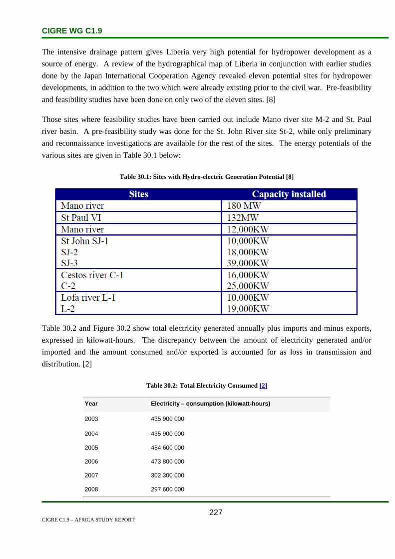
CIGRE WG C1.9
CIGRE C1.9 – AFRICA STUDY REPORT
227
The intensive drainage pattern gives Liberia very high potential for hydropower development as a
source of energy. A review of the hydrographical map of Liberia in conjunction with earlier studies
done by the Japan International Cooperation Agency revealed eleven potential sites for hydropower
developments, in addition to the two which were already existing prior to the civil war. Pre-feasibility
and feasibility studies have been done on only two of the eleven sites. [8]
Those sites where feasibility studies have been carried out include Mano river site M-2 and St. Paul
river basin. A pre-feasibility study was done for the St. John River site St-2, while only preliminary
and reconnaissance investigations are available for the rest of the sites. The energy potentials of the
various sites are given in Table 30.1 below:
Table 30.1: Sites with Hydro-electric Generation Potential [8]
Table 30.2 and Figure 30.2 show total electricity generated annually plus imports and minus exports,
expressed in kilowatt-hours. The discrepancy between the amount of electricity generated and/or
imported and the amount consumed and/or exported is accounted for as loss in transmission and
distribution. [2]
Table 30.2: Total Electricity Consumed [2]
Year Electricity – consumption (kilowatt-hours)
2003 435 900 000
2004 435 900 000
2005 454 600 000
2006 473 800 000
2007 302 300 000
2008 297 600 000

CIGRE WG C1.9
CIGRE C1.9 – AFRICA STUDY REPORT
228
Figure 30.2: Total Electricity Consumed Expressed in Kilowatt-hours [2]
30.3 Planning and Design Criteria
‘Liberia has a population of 3.3 million, 1 350 000 of whom live in and around the capital, Monrovia.
Liberia has no transmission system (only distribution) and its generation capacity is below 10 MW. A
handicap is its use of 60 Hz AC frequency, which would substantially increase the costs of
interconnection with other countries in this region. Technically, this could only be done via DC links
or frequency converter stations.
It is recommended that international financial institutions consider funding to study conversion to 50
Hz frequency. There would be substantial benefit in doing this now, before the problem gets bigger
and more expensive to solve as the electricity system expands. Liberia demand forecast is shown in
Table 30.3, from ECOWAS Data Set #6. However, this is not considered to be realistic since Liberia is
believed to have only 9 MW installed capacity of diesel plant in Monrovia. The energy and peak
demand forecast implies a load factor of 100 per cent, which is clearly impossible.’ [10]
Table 30.3: Liberia Electricity Demand Forecast [10]
2003 2007 2011 2015 2020
MW 44 58 105 122 122
GWh 387 505 917 1072 1072

CIGRE WG C1.9
CIGRE C1.9 – AFRICA STUDY REPORT
229
30.4 Planning Approaches and Methods
In the medium term, Liberia’s plan is to complete the re-installation of a basic grid for Monrovia, tying
together all the distribution systems already constructed in the Strong Leopard Spots project (Ref
30.6). The European Commission has generously committed to a grant of over US$16.5 million to
complete this work [6].
As activity gets under way, private financing through an IPP will be sought to install 20–30 MW of
Heavy Fuel Oil (HFO) generation on Bushrod, to energize the new grid. The temporary diesel
generators installed under EPP I and II will be moved to more rural areas to begin the electrification
process there [6].
Given the poor international credit status of Liberia, innovative methods may have to be used to raise
this financing. One method involving a 5-year electricity concession has already been formulated by
the International Finance Corporation [6].
Simultaneously with the implementation of this plan will be vigorous energy sector reform. Basic
elements like the rights of private generators, the structure of the LEC, and an energy regulatory
commission, are still pending [6].
It has been proposed that a separate rural electrification agency, independent of the regulatory
commission and LEC, be established. This will speed up the delivery of affordable electricity services
to the hinterlands, where electricity has never been seen before [6].
30.5 Specific Technical Issues
Liberia has no transmission system (only distribution) and its generation capacity is below 10 MW. A
handicap is its use of the 60 Hz AC frequency, which would substantially increase the costs of
interconnection with other countries in this region. Technically, this could only be done via DC links
or frequency converter stations [3].
It is recommended that international financial institutions consider funding to study conversion to
50 Hz frequency. There would be substantial benefit in doing this now, before the problem gets bigger
and more expensive to solve as the electricity system expands [3].
Recovering from 14 years of civil war, Liberia has been without public power since the start of the war
in the early 1990s, when the main hydropower plant was damaged and its vital components looted.
Over the last decade, looters have stolen most of Monrovia’s electricity cables for sale as scrap metal
[4].
CIGRE WG C1.9
CIGRE C1.9 – AFRICA STUDY REPORT
230
Since 2006, Liberia’s post-war government has been providing ‘emergency power’ using generators
obtained on loan from Ghana to supply power to a few street lights and select public buildings, like
hospitals [4].
The Emergency Power Program (EPP) is being funded by Ghana through the Volta River Authority,
the Libyan government and Liberia’s development partners, including the European Union and the US
Agency of International Development [4].
The LEC’s pre-war power system consisted of hydro and thermal generating facilities with a combined
installed capacity of 182 MW. Hydro accounted for 64 MW and gas-fired turbines, slow-speed diesel-
fired plants and medium-speed diesel-fired plants contributed 68 MW, 40 MW and 10 MW
respectively. The average annual energy production of these plants stood at 435 GWh, prior to the
1989 war [4].
Meanwhile, the European Commission (EC) has approved €4.8 million contribution to a programme
linking three of Liberia’s border regions to the West African Power Pool (WAPP). Liberia joined the
WAPP, a regional power supply group set up in 1999 by West African leaders to tackle the challenge
of power supply deficiencies in the Economic Community of West African States region [4].
30.6 Financing Issues
The Liberian government has contracted US-based engineering company to carry out studies on the
feasibility of resuscitating the country’s only hydropower plant, which was damaged during the
country’s civil war. The US government, through the US Trading Authority, has given more than
US$531 000 for feasibility studies on the resuscitation of the damaged hydro plant [4].
Based on the very early results of the EPP in Liberia, the government of Norway decided to grant
US$7.8 million for further generation in Monrovia. As the original donors, the EC, World Bank, and
US, wanted to support continuing stabilization efforts and build on their growing electricity success,
and they formed a new coalition with the government of Liberia and now Norway, in December 2006.
This new programme, dubbed EPP II, eventually totaled US$25 million of aid, including
US$1.8 million of budget support from the government of Liberia [6].
These funds are to be employed in a plan called Strong Leopard Spots. New generation sites and
distribution systems will be constructed in the districts of Paynesville and Bushrod Island. The
generators and systems in Congotown and Krutown are to be reinforced and expanded. When
complete, this project will add another 7 MW of power to Monrovia and extend the electricity service
into neighbourhoods that in total represent 70% of the city’s population [6].

CIGRE WG C1.9
CIGRE C1.9 – AFRICA STUDY REPORT
231
Figure 30.3: Growth in LEC Customers and Collections [6]
Plans and changes to the electricity industry are dependent on the continued success of the LEC in
collection and anti-theft measures. Discipline and control of these two commercial business drivers
will determine when, and if, the international financial community is willing to fund further
electrification of Liberia [6].
30.7 Human Resources
The United Nations Development Programme (UNDP) has appointed the Volta River Authority
(VRA), Ghana’s electricity utility, as the principal consulting agency that implemented the Emergency
Power Programme (EPP) beginning with a section of Monrovia [9].
The VRA crews assisted with the installation of electricity poles and the restringing of cables from the
LEC headquarters in the Krutown district to downtown Monrovia. The crews also cut down the old
tangle of illegal taps and disused wires and reinstalled a new and clean distribution grid [6].
30.8 References
1. Wikipedia. ‘Liberia’. URL http://en.wikipedia.org/wiki/Liberia. Last accessed:
3 September 2009.

CIGRE WG C1.9
CIGRE C1.9 – AFRICA STUDY REPORT
232
2. Index Mundi. ‘Liberia Electricity – consumption’.
URL http://www.indexmundi.com/liberia/electricity_consumption.html. Last accessed:
1 September 2009.
3. Nexant Inc. ‘West Africa Regional Transmission Stability Study’. Volume 2: Master Plan.
URL http://www.ecowapp.org/Volume 2 Master Plan - Final.pdf. Last accessed:
3 September 2009.
4. Engineering News. ‘Liberia studies feasibility of reviving sole hydropower plant’. URL
http://www.engineeringnews.co.za/article/liberia-studies-feasibility-of-reviving-sole-
hydropower-plant-2008-03-07. Last accessed: 14 September 2009.
5. Wikipedia. ‘Mount Coffee Hydropower Project’.
URL http://en.wikipedia.org/wiki/Mount_Coffee_Hydropower_Project Last accessed:
3 September 2009.
6. Rick Whitaker ‘Let there be light: The role of electrification in Liberia’s post-conflict
stabilization’. URL http://www.worldenergy.org/documents/p000745.pdf Last accessed:
14 September 2009.
7. eStandardsforum ‘Country brief: Liberia’.
URL http://www.estandardsforum.org/secure_content/country_profiles/cp_104.pdf Last
accessed: 14 September 2009.
8. United Nations Development Programme. ‘First State of the Environment Report for
Liberia - 2006’. http://www.lr.undp.org/State of the environment report final.pdf Last
accessed: 16 September 2009.
9. Volta River Authority. ‘Regional Co-operation’. http://www.vra.com/Power/regcop.php
Last accessed: 16 September 2009.
10. Final Report ‘West Africa Regional Transmission Stability Study’. Volume 2: Master Plan,
http://www.ecowapp.org/Volume%202%20Master%20Plan%20-%20Final.pdf]
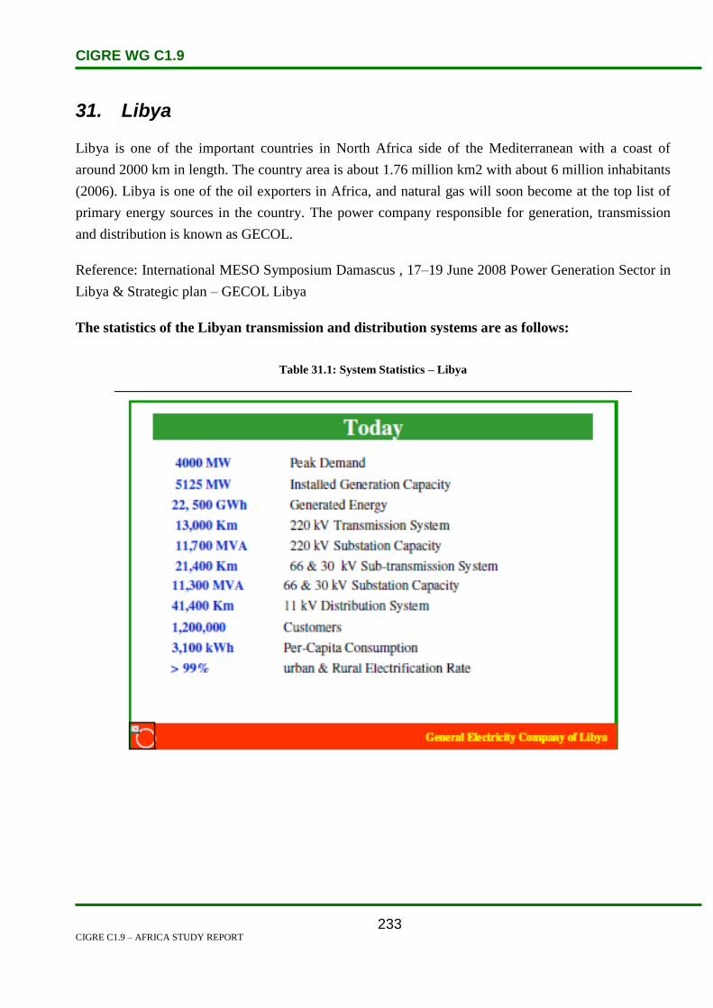
CIGRE WG C1.9
CIGRE C1.9 – AFRICA STUDY REPORT
233
31. Libya
Libya is one of the important countries in North Africa side of the Mediterranean with a coast of
around 2000 km in length. The country area is about 1.76 million km2 with about 6 million inhabitants
(2006). Libya is one of the oil exporters in Africa, and natural gas will soon become at the top list of
primary energy sources in the country. The power company responsible for generation, transmission
and distribution is known as GECOL.
Reference: International MESO Symposium Damascus , 17–19 June 2008 Power Generation Sector in
Libya & Strategic plan – GECOL Libya
The statistics of the Libyan transmission and distribution systems are as follows:
Table 31.1: System Statistics – Libya

CIGRE WG C1.9
CIGRE C1.9 – AFRICA STUDY REPORT
234
Figure 31.1: System Statistics – Libya
The generation, energy consumption and electrical demand statistics of the Libyan electricity
system are as shown below in Table 31.2:
Table 31.2: Statistical Data – Libya – 2008
Installed Capacity by Type of Generation (MW) – 2008
Thermal 6 196
Steam Turbines 1 747
Gas Turbines 2 094
Combined Cycle 2 355
Diesel
Hydro
Renewables
Others
Total 6 196
Yearly generation by type (GWh) – 2008
Thermal 28 666
Steam Turbines 7 264
Gas Turbines 1 1519
Combined Cycle 9 883
Diesel
Hydro
Renewables
Others
Total 28 666
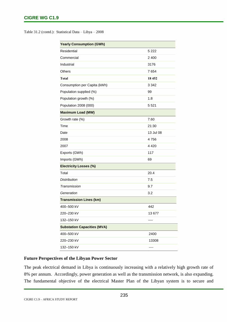
CIGRE WG C1.9
CIGRE C1.9 – AFRICA STUDY REPORT
235
Table 31.2 (contd.): Statistical Data – Libya – 2008
Yearly Consumption (GWh)
Residential 5 222
Commercial 2 400
Industrial 3176
Others 7 654
Total 18 452
Consumption per Capita (kWh) 3 342
Population supplied (%) 99
Population growth (%) 1.8
Population 2008 (000) 5 521
Maximum Load (MW)
Growth rate (%) 7.60
Time 21:30
Date 13 Jul 08
2008 4 756
2007 4 420
Exports (GWh) 117
Imports (GWh) 69
Electricity Losses (%)
Total 20.4
Distribution 7.5
Transmission 9.7
Generation 3.2
Transmission Lines (km)
400–500 kV 442
220–230 kV 13 677
132–150 kV ----
Substation Capacities (MVA)
400–500 kV 2400
220–230 kV 13308
132–150 kV ----
Future Perspectives of the Libyan Power Sector
The peak electrical demand in Libya is continuously increasing with a relatively high growth rate of
8% per annum. Accordingly, power generation as well as the transmission network, is also expanding.
The fundamental objective of the electrical Master Plan of the Libyan system is to secure and

CIGRE WG C1.9
CIGRE C1.9 – AFRICA STUDY REPORT
236
guarantee the electrical power supply to meet the growing demand for electrical energy in all sectors in
the country. Recent studies have shown that the peak demand in Libya is expected to reach about
10 000 MW by year 2015 and around 14 000 MW by 2020. Therefore, a total of about 5 500 MW
generation capacity needs to be added during the period 2006–2012 with mixed generation options
(Steam & Combined Cycle) using natural gas.
In order to transmit the electrical energy generated from the various power plants and to reinforce the
local interconnections and interconnections with neighbouring countries (Egypt & Tunisia), the future
development plan of the Libyan Transmission System is concentrated on the 400 kV grid. The 400 kV
network will be implemented by constructing 20 (400/220 kV) substations and about 5 000 km of 400
kV transmission lines.
31.1 Electricity Industry Structure
The Transmission System Operator (TSO), GECOL, is the sole operator of the national transmission
network (400, 220, 66 and 30 kV). Within GECOL’s organization, there is a department responsible
for energy management and transmission. A ‘three-level structure’ control centre has been constructed
and is being put into operation. The National Control Center (NCC), located in Sirte, is equipped with
the latest technologies such as AGC and EMS, and relies on a telecommunication system based on a
fiber optic network. This NCC monitors and controls the HV and EHV networks in addition to
generation plants, and also interacts with the neighbouring national control centres for the
interconnection operation.
Libya also has two Regional Control Centers:
Benghazi’s Regional Control Center (BRCC), in operation since 2001 to control the 220 kV
system in the eastern region of the grid, and
Tripoli’s Regional Control Center (TRCC), recently established.
Furthermore, ten distribution control centers (DCCs) are scheduled to be constructed in the next five
years. These control centers will control the distribution network (66, 30 and 11 kV) all over the
country.
Generation: all the power plants are owned and operated by GECOL. IPPs do not exist.
Distribution: GECOL acts as a single distributor. GECOL has a department responsible for the
operation and maintenance of the distribution network. Furthermore, there are ten regional departments
carrying out the distribution work.
Main traders & other players (power exchange etc.): GECOL acts as a single trader in the electricity
market.
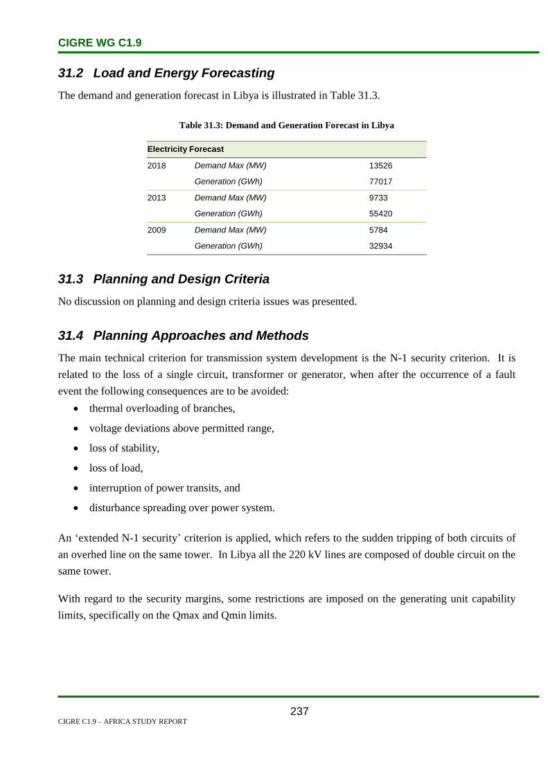
CIGRE WG C1.9
CIGRE C1.9 – AFRICA STUDY REPORT
237
31.2 Load and Energy Forecasting
The demand and generation forecast in Libya is illustrated in Table 31.3.
Table 31.3: Demand and Generation Forecast in Libya
Electricity Forecast
2018 Demand Max (MW) 13526
Generation (GWh) 77017
2013 Demand Max (MW) 9733
Generation (GWh) 55420
2009 Demand Max (MW) 5784
Generation (GWh) 32934
31.3 Planning and Design Criteria
No discussion on planning and design criteria issues was presented.
31.4 Planning Approaches and Methods
The main technical criterion for transmission system development is the N-1 security criterion. It is
related to the loss of a single circuit, transformer or generator, when after the occurrence of a fault
event the following consequences are to be avoided:
thermal overloading of branches,
voltage deviations above permitted range,
loss of stability,
loss of load,
interruption of power transits, and
disturbance spreading over power system.
An ‘extended N-1 security’ criterion is applied, which refers to the sudden tripping of both circuits of
an overhed line on the same tower. In Libya all the 220 kV lines are composed of double circuit on the
same tower.
With regard to the security margins, some restrictions are imposed on the generating unit capability
limits, specifically on the Qmax and Qmin limits.

CIGRE WG C1.9
CIGRE C1.9 – AFRICA STUDY REPORT
238
With regard to the capability of lines and transformers, the operational planning units in the national
dispatching centres usually do not define different thermal ratings for winter and summer operational
conditions, as happens in Europe, but rather for normal and emergency conditions. Moreover,
different ratings are defined based on the age of equipment.
Generally, for reliability analysis probabilistic approaches or the assessment of the probability of N-1
events during transmission system planning are not considered. Methods used by transmission
planners are based on the deterministic approach, and the probabilities of the occurrence of the various
events (network failures, generator dispatch, branches availability, etc.) are not taken into
consideration. Such approaches can be found only in some studies performed by foreign consulting
companies.
Load flow computations, static security analysis, short circuit calculations and system stability analysis
are carried out during the planning process. Optimal power flows and static/dynamic analyses for
post-emergency conditions are also carried out, though not as a routine task.
Uncertainties are mostly taken into account using multi-scenario analysis. The most important
uncertainties are:
the size and location of new power plants,
generator availability,
load forecasts, and
country power balance.
The North African power utilities do not have any specific construction criteria for interconnection
lines, but commissioning of an interconnection requires a higher hierarchical level of analysis where
possible incoherency in planning criteria and system constraints are solved, as well as all aspects
related to the engineering issues and co-ordination (e.g.: protection philosophy and relay settings).
Considering the complexity of interconnection studies, quite often the prefeasibility and feasibility
studies for the different kinds of interconnections (HVAC, HVDC) are performed by foreign
consulting companies. The specific economic criteria for interconnection lines are based on difference
in electricity prices or on the overall change in system operational costs derived by different
interconnection options and different operating regimes of power systems.
The planning and operational criteria of Libya are converging towards the criteria adopted in UCTE, in
view of a possible extension of the synchronous area with Europe, which at present is limited to
Morocco, Algeria and Tunisia.

CIGRE WG C1.9
CIGRE C1.9 – AFRICA STUDY REPORT
239
N security conditions
The basic assumptions related to the N criterion of the transmission network are:
The rating limits of transmission lines should be intended as maximum permanent currents.
In normal operating conditions, no overload of the transmission network is allowed.
No generator will be above its continuous reactive capability with possible restrictions decided
by the planner to account for operational constraints.
The loads are represented as constant active and reactive powers.
In normal operating conditions a long-term overload of transformers up to 10% of nominal
rating is allowed. A short term overload (less than 15 minutes) is allowed up to 20%.
For the transmission system generally, unless otherwise specified, the maximum operating voltages are
as follows:
For 400 kV network maximum voltage is 420 kV.
For 220 kV network maximum voltage is 231 kV.
For 132 kV network maximum voltage is 145.2 kV.
For 90 kV network maximum voltage is 95 kV.
For 66 kV network maximum voltage is 72.6 kV.
The minimum operating voltages values are as follows:
For 400 kV network minimum voltage is 380 kV.
For 220 kV network minimum voltage is 209 kV.
For 132 kV network minimum voltage is 118.8 kV.
For 90 kV network minimum voltage is 85 kV.
For 66 kV network minimum voltage is 59.4 kV.
Operating Frequency:
The nominal frequency is 50 Hz and its permissible variation range under AGC is 50 ± 0.05 Hz.
Under normal operating condition the maximum permissible variation range is50 ± 0.2 Hz.
N-1 Security Conditions
The following criteria are applied under N-1 contingency conditions:
The transmission system should be planned such that reasonable and foreseeable contingencies
do not result in the loss or unintentional separation of a major portion of the network or in the
separation from the regional interconnected system.
CIGRE WG C1.9
CIGRE C1.9 – AFRICA STUDY REPORT
240
During contingency conditions, a temporary overload of the transmission lines is allowed up to
10%.
A temporary overload of transformers is allowed in emergency conditions up to 20% during
peak hours.
The maximum post-transient voltage deviation is 10%.
For the transmission system generally, unless otherwise specified, the maximum operating voltage
values are as follows:
For 400 kV network maximum voltage is 440 kV.
For 220 kV network maximum voltage is 242 kV.
For 132 kV network maximum voltage is 151.8 kV.
For 66 kV network maximum voltage is 72.6 kV.
The minimum operating voltage values are as follows:
For 400 kV network minimum voltage is 360 kV.
For 220 kV network minimum voltage is 198 kV.
For 132 kV network minimum voltage is 112.2 kV.
For 66 kV network minimum voltage is 59.4 kV.
Operating frequency:
During N-1 contingency conditions, the maximum and minimum permissible frequencies are
50.4 Hz and 49.6 Hz respectively.
In the case of a severe incident, the maximum and minimum permissible frequency limits are
52 Hz and 47.5 Hz respectively.

CIGRE WG C1.9
CIGRE C1.9 – AFRICA STUDY REPORT
241
Transmission Network Planning Probabilistic Approach
The probabilistic approach is seldom used in planning studies directly by the concerned TSOs or VIUs.
However, the probabilistic approach is being widely used in interconnection studies among the North
African Countries (e.g.: the MEDRING and the ELTAM studies).
Unless specific data is provided, the basic assumptions adopted concerning the unavailability of the
transmission system, are given in Table 29.4.
Table 31.4: Transmission Line Forced Unavailability Rate
VOLTAGE LEVEL
[kV]
UNAVAILABILITY RATE
[p.u./100 km]
500–400 0.005
220 0.0025
150–90 0.005
As no reliability data on the transformers is available, standard hypotheses for these values are
assumed. It is assumed that the transformers have an availability of 99.5%.
Also records on the reliability of reactors and capacitors are not available, hence standard hypotheses
for these values are adopted. More specifically, it is assumed that the reactive compensation
equipment has an availability of 99.5%.
Three different weather conditions, Normal, Bad and Stormy, are considered and, unless otherwise
specified, the parameters used to simulate the weather effects are set out in Table 29.5.
Table 31.5: Parameters of Weather Model
Weather Conditions Hours Ratio
[p.u.]
Coefficients
[p.u.]
Normal 0.9667 1.0
Bad 0.03 10.0
Stormy 0.003 15.0
As an indicator of the system adequacy, the annual value of Expected Energy Not Supplied (EENS)
due to unavailability in the transmission system and/or generation, considering the constraints
represented by the transmission capacities of the lines and active power limits of the power plants, is
used.
A threshold value 10-4 p.u. for the EENS index related to insufficiency of the transmission system due
to a reduction in the transmission capacity of the network is assumed.

CIGRE WG C1.9
CIGRE C1.9 – AFRICA STUDY REPORT
242
Economic evaluation in transmission-generation planning
The price of EENS for an economic evaluation can vary from 0.5US$/kWh up to 2US$/kWh.
The generation margins and the loss of load probability adopted for the reliability study are the
following:
Minimum generation margin reserve: 15%.
Loss of load probability (LOLP): one day per three years.
Power reserve requirements and criteria
Power systems in North Africa are operated with a primary frequency control and a LFC (Load
Frequency Control). Primary and Secondary reserves are determined by each operator.
The frequency and active power control is provided by the following means:
Automatic response from generating units operating in a free governor frequency sensitive
mode (Primary Reserve).
Automatic Generation Control (AGC) of generating units equipped with automatic load
frequency control (Secondary Reserve).
To ensure network security in the EEHC and other national systems composing the South-Eastern
Mediterranean synchronous pool (Libya, Jordan, Syria, Lebanon), after the most severe outage
considered, the total needed Primary Control Reserve is pre-determined at a value of 250 MW
composed of 150 MW thermal reserve and 100 MW hydro reserve.
As for the Secondary Reserve, there are 20 units of TPP and 10 units of HPP under the AGC. The goal
of Secondary Control Reserve is to restore frequency and cross-border exchange to the set values.
Hereafter the characteristics of actual operating reserves for power production are reported. They are
used as reference values.
Table 31.6: Operational Criteria for Definition of Operating Reserve in Libya
Value
MW
Primary spinning reserve (within 30 sec) 250 100 MW Hydro Generation
150 MW Thermal Generation
Secondary spinning reserve (within 14.5 minutes):
In winter 350 Hydro-Thermal generation
175 Hydro-Thermal generation
175 Interconnection lines
Cold reserve (within 15 minutes) 600 Gas turbines
Type of Operating Reserve Comments
In summer

CIGRE WG C1.9
CIGRE C1.9 – AFRICA STUDY REPORT
243
31.5 Specific Technical Issues
Figure 31.2: Recent accomplishments
31.6 Financing Issues
Transmission investments are mostly financed through transmission fees, loans, internal sources and
very few by private investors.
Economic Criteria (capital investment, IRR, NPV), are applied in transmission network planning. In
the economic evaluations, the reduction in the cost of the losses is usually estimated, but additional
benefits related to the reduction of congestion costs are also taken into account as well as the increase
of transmission service revenues.
Generally, the transmission system operators (TSOs) or the vertically integrated undertakings (VIUs)
have not defined the cost of EENS and the applied values are agreed for each study among the local
experts and also taking into account the experience of the Consulting companies, whenever they are
involved in the execution of the transmission system studies. Usually, the undelivered electricity costs
across North Africa range between 0.5 and 2US$/kWh.
Market-oriented transmission investments (merchant lines) and investments from a regional
perspective are not applied. National transmission networks are mainly planned according to technical
considerations and economic rationalization of new investments.

CIGRE WG C1.9
CIGRE C1.9 – AFRICA STUDY REPORT
244
31.7 Human Resources
No discussion on human resource issues was presented.

CIGRE WG C1.9
CIGRE C1.9 – AFRICA STUDY REPORT
245
32. Madagascar
32.1 Electricity Industry Structure
In 2002 Madagascar’s electricity production was 840.2 million kWh and its electricity consumption
was 781.4 million kWh. This is extremely low and makes Madagascar one of the smallest energy
consumers in Africa. [1] Currently the electricity production is 1.05 million kWh.
Hydropower generated 64.9% of electricity in 2005 and thermal (mostly oil and diesel) the remainder.
There is an untapped potential capacity of 7 GW of hydroelectric power. Only 200 MW are presently
being exploited. An additional 400 MW of hydropower is expected to become operational by 2012.
There is at present no coal production but Uranio Ltd, (Australia) is exploring for coal and Straits Asia
Resources (a Singapore company that is owned 47% by Australia Straits Resources) and Pan African
Mining (Canada) have rights to explore for coal. Coal production from the Sakoa mine will begin in
2010 at a rate of 5 mn tons a year.[2]
In 2011, Madagascar had a total installed renewable capacity (biomass, geothermal,
hydroelectricity,solar and wind) of 132 megawatts, an increase of 2 megawatts (1,74%) on the
previous year.Over the previous five years,the total installed renewable energy capacity has increased
by 8 megawatts or 1,29% on a five year compound growth basis. Globally the Madagascar renewable
energy market ranks at #117 for total installed renewable capacity, behind Luxembourg (140 MW) and
ahead of Cuba (132 MW). The world leader for total installed renewable energy capacity in 2011 was
China with 301,440 MW, 2280 times larger than Madagascar.
Jirama, the state run energy and water supplier, is currently being privatized, and the company is
diversifying energy-generation sources in order to increase supplies and reduce costs, thus tackling two
factors that have long handicapped mining and other industries. The privatization process of the
company involves the rehabilitation of installations, and, although thermal power plants are believed to
be numerous, there is a need for hydroelectricity. Also, within the privatization process of the
company, there is believed to be a need for electricity market liberalization, especially in production.
There are private companies that generate some electricity.
Like most major cities on Madagascar, Mahajanga and Toliara are not 100 percent electrified. They
fall into the 30 percent range with power needs of 4 to 6MW. Only 2 to 3MW of power is supplied by
JIRAMA, the local utility. Unfortunately, the towns suffer frequent blackouts, some lasting as long as
20 hours per day, as the local utility switches which zones receive power on an hour-to-hour basis. The

CIGRE WG C1.9
CIGRE C1.9 – AFRICA STUDY REPORT
246
electrification rate is 45% for urban areas and only 5% for rural areas.
In 2007, Henri Fraise Fils & Cie (HFFC) of Antananarivo, Madagascar, was determined to find a way
to provide a base load electrical supply for both Mahajanga and Toliara and help curb the energy
concerns of the cities. The lack of electricity had a severe impact on business as well as the
population.
Figure 32.1: Electricity production for 2000-2011
GWh

CIGRE WG C1.9
CIGRE C1.9 – AFRICA STUDY REPORT
247
Figure 32.2: Electricity consumption for 2000-2011
Figure 32.3: Madagascar Renewable Capacity over a 5 year period.
GWh
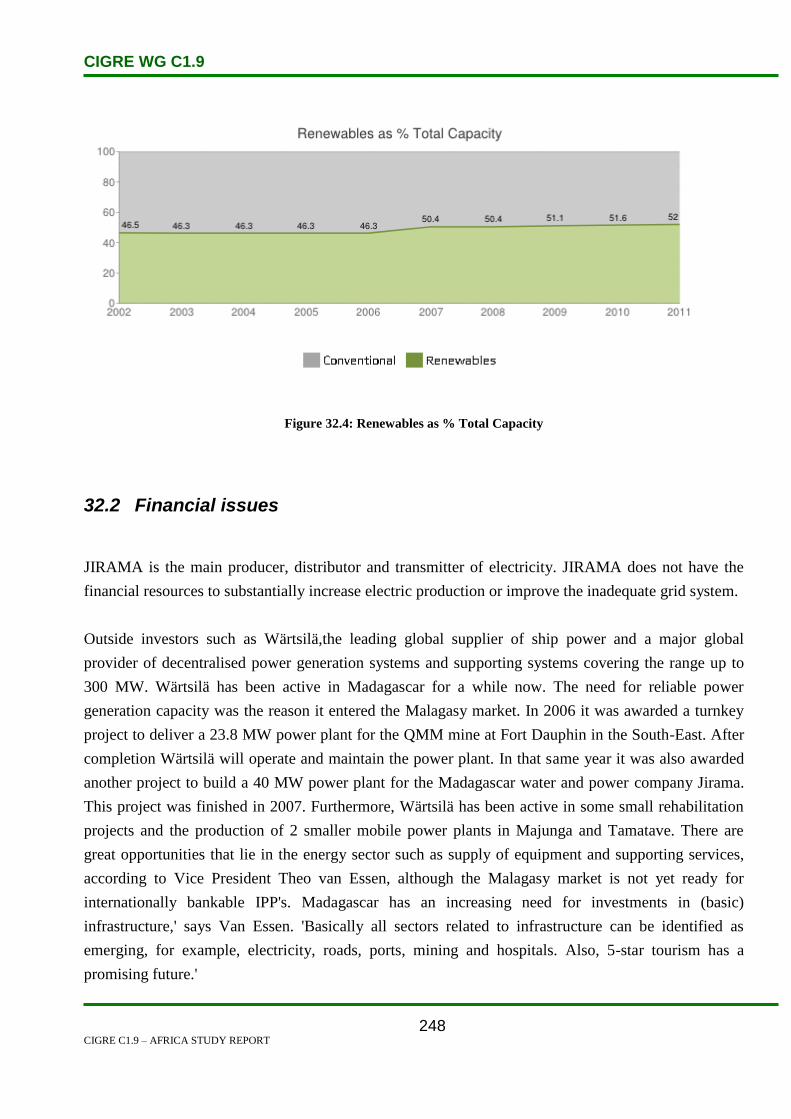
CIGRE WG C1.9
CIGRE C1.9 – AFRICA STUDY REPORT
248
Figure 32.4: Renewables as % Total Capacity
32.2 Financial issues
JIRAMA is the main producer, distributor and transmitter of electricity. JIRAMA does not have the
financial resources to substantially increase electric production or improve the inadequate grid system.
Outside investors such as Wärtsilä,the leading global supplier of ship power and a major global
provider of decentralised power generation systems and supporting systems covering the range up to
300 MW. Wärtsilä has been active in Madagascar for a while now. The need for reliable power
generation capacity was the reason it entered the Malagasy market. In 2006 it was awarded a turnkey
project to deliver a 23.8 MW power plant for the QMM mine at Fort Dauphin in the South-East. After
completion Wärtsilä will operate and maintain the power plant. In that same year it was also awarded
another project to build a 40 MW power plant for the Madagascar water and power company Jirama.
This project was finished in 2007. Furthermore, Wärtsilä has been active in some small rehabilitation
projects and the production of 2 smaller mobile power plants in Majunga and Tamatave. There are
great opportunities that lie in the energy sector such as supply of equipment and supporting services,
according to Vice President Theo van Essen, although the Malagasy market is not yet ready for
internationally bankable IPP's. Madagascar has an increasing need for investments in (basic)
infrastructure,' says Van Essen. 'Basically all sectors related to infrastructure can be identified as
emerging, for example, electricity, roads, ports, mining and hospitals. Also, 5-star tourism has a
promising future.'
CIGRE WG C1.9
CIGRE C1.9 – AFRICA STUDY REPORT
249
32.3 References
1. www.mbendi.com/a_sndmsg
2. www.estandardsforum.org
3. http://www.cat.com
4. http://www.nabc.nl

CIGRE WG C1.9
CIGRE C1.9 – AFRICA STUDY REPORT
250
33. Malawi
33.1 Electricity Industry Structure
Malawi is a country surrounding Lake Malawi and borders Zambia, Tanzania and Mozambique. It has
a total land area of 118 484 km² and a population of 12.5 million. At present only 7% of the
population have access to electricity.
Malawi is well-endowed with renewable energy sources, including good sunshine throughout the year
for photo-voltaic (PV) and photo-thermal applications, reasonable wind speeds for water pumping,
domesticated animals for biogas applications, and hot springs for geothermal power generation. About
5 000 PV systems have been installed, but more than 50% of them are malfunctioning or have
completely stopped working.
The Electricity Supply Corporation of Malawi (ESCOM) Ltd. is a public utility which is responsible
for generation, transmission, distribution and retail electricity services nationwide, through its
interconnected and off-grid power supply systems. The utility is owned almost wholly by the
Government of Malawi (99%), and 1% is held by the Malawi Development Corporation (MDC).
ESCOM reports to the Ministry of Energy and Mining (MEM). No other players (apart from some
industrial self-generators, e.g. in the sugar industry) are currently directly involved in the distribution
of power to customers. Figure 33.1 illustrates the Electricity supply structure for Malawi.
New legislation has opened up the market for private enterprise and for local authorities to consider
entering the power market, and especially the electricity distribution industry.
Figure 33.1: Electricity Supply Industry Structure in Malawi

CIGRE WG C1.9
CIGRE C1.9 – AFRICA STUDY REPORT
251
The Government of Malawi has undertaken a series of reforms aimed at re-energizing the Electricity
Supply Industry. This has involved changing the legislative and regulatory framework aimed at
separating the regulatory functions from operations. The oversight role in relation to the ESI will be
vested in the Malawi Energy Regulatory Authority (MERA). The MERA is an independent regulator,
set up to undertake issues pertaining to licensing and regulating power producers. This is in line with
the new Electricity Act, which allows private investors in the electricity market.
The Government of Malawi is unbundling ESCOM into three business units, namely Generation,
Transmission and Distribution. Ultimately, the Government of Malawi will introduce Private Sector
Participation (PSP) in ESCOM. ESCOM’s Utility data is summarized in Table 33.1.
Table 33.1: ESCOM Utility Data – Malawi
Escom Data
Installed capacity MW (2005) 285
Maximum demand MW 259.67
MD growth % 8
Sales GWh 1218
Sales growth % 8
Number of customers 172 924
Generation sent out GWh 1543
Net import GWh -
Net export GWh -
Transmission losses % 21
33.2 Load and Energy Forecasting
The country’s maximum demand electricity growth rate stands at 8% and the sales growth rate is also
8%.
ESCOM employs the following forecast methodologies for load and energy forecasting:
Historical trend analysis, and
Sectoral analysis.
Malawi’s power demand will increase by around 70% to 767 MW by 2020. Tables 33.2 and 33.3
show Malawi’s electricity maximum demand and sales forecast respectively.

CIGRE WG C1.9
CIGRE C1.9 – AFRICA STUDY REPORT
252
Table 33.2: Maximum Demand Forecast in Malawi
Year Base Case
MW
High Case
MW
Low Case
MW
2008 295 312 281
2009 324 377 284
2010 355 440 293
2011 386 499 304
2012 423 552 322
2013 457 597 342
2014 492 644 362
2015 528 693 383
2016 566 744 405
2017 605 796 428
2018 646 851 453
Table 33.3: Sales Forecast in Malawi
Year Base Case
GWh
High Case
GWh
Low Case
GWh
2007/08 1 224
2008/09 1 679 1 776 1 601
2009/10 1 846 2 145 1 614
2010/11 2 020 2 508 1 668
2011/12 2 196 2 839 1 728
2012/13 2 408 3 141 1 835
2013/14 2 601 3 400 1 945
2014/15 2 801 3 668 2 060
2015/16 3 008 3 946 2 181
2016/17 3 224 4 234 2 307
2017/18 3 448 4 532 2 439
2018/19 3 681 4 843 2 578
33.3 Planning and Design Criteria
In electricity production, hydropower is the dominant source of power generation, with over 95% of
the electricity produced by ESCOM hydro-based. ESCOM is the country’s only large-scale producer
of electricity. ESCOM operates power stations with a combined capacity of 285 MW from six
hydroelectric plants. The main hydro power stations are located in the south of the country and the rest
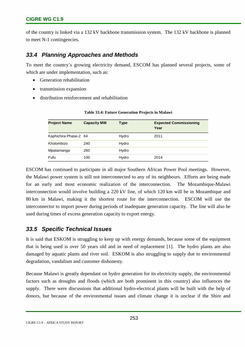
CIGRE WG C1.9
CIGRE C1.9 – AFRICA STUDY REPORT
253
of the country is linked via a 132 kV backbone transmission system. The 132 kV backbone is planned
to meet N-1 contingencies.
33.4 Planning Approaches and Methods
To meet the country’s growing electricity demand, ESCOM has planned several projects, some of
which are under implementation, such as:
Generation rehabilitation
transmission expansion
distribution reinforcement and rehabilitation
Table 33.4: Future Generation Projects in Malawi
Project Name Capacity MW
Type
Expected Commissioning
Year
Kaphichira Phase-2 64 Hydro 2011
Kholombizo 240 Hydro
Mpatamanga 260 Hydro
Fufu 100 Hydro 2014
ESCOM has continued to participate in all major Southern African Power Pool meetings. However,
the Malawi power system is still not interconnected to any of its neighbours. Efforts are being made
for an early and most economic realization of the interconnection. The Mozambique-Malawi
interconnection would involve building a 220 kV line, of which 120 km will be in Mozambique and
80 km in Malawi, making it the shortest route for the interconnection. ESCOM will use the
interconnector to import power during periods of inadequate generation capacity. The line will also be
used during times of excess generation capacity to export energy.
33.5 Specific Technical Issues
It is said that ESKOM is struggling to keep up with energy demands, because some of the equipment
that is being used is over 50 years old and in need of replacement [1]. The hydro plants are also
damaged by aquatic plants and river soil. ESKOM is also struggling to supply due to environmental
degradation, vandalism and customer dishonesty.
Because Malawi is greatly dependant on hydro generation for its electricity supply, the environmental
factors such as droughts and floods (which are both prominent in this country) also influences the
supply. There were discussions that additional hydro-electrical plants will be built with the help of
donors, but because of the environmental issues and climate change it is unclear if the Shire and
CIGRE WG C1.9
CIGRE C1.9 – AFRICA STUDY REPORT
254
Zambezi rivers will be capable to deliver adequate flows in the future. This makes the alternative to
connect to Mozambique’s Cahora-Bassa plant even more feasible.
33.6 Financing Issues
Malawi has, after a long power struggle, received some relief from the US government and the
Millennium Challenge Corporation (MCC) in the form of a K53 billion grant to rehabilitate ESKOM’s
generation infrastructure.
The World Bank has also committed 200 million dollars for the project to interconnect the Malawi and
Mozambique grid, thus connecting them to the SAPP. This will also help to lighten the electricity load
by spreading the demand, not only from Mozambique, but from the SAPP. Because of political issues
and bad governance from the Malawian government, it is said that Washington will not release the
money for this connection [2].
33.7 Human Resources
Although ESKOM plays the predominant role in Malawi’s power generation, its role in terms of
human resources is unclear. Because of the on-going energy struggle and lack of funds Malawi is
mainly dependant on donors and international grants to further improve their generation capacity and
also branch out into other generation methods such as: biogas, wind energy, solar energy etc.
Global Television & Solar is an example of one of the companies that has been approached to do all of
the solar installations in Malawi.
33.8 References
1. http://allafrica.com/stories/201103010030.html
2. http://www.africanews.com/site/MALAWI_Power_cuts_threaten_lives/list_messages
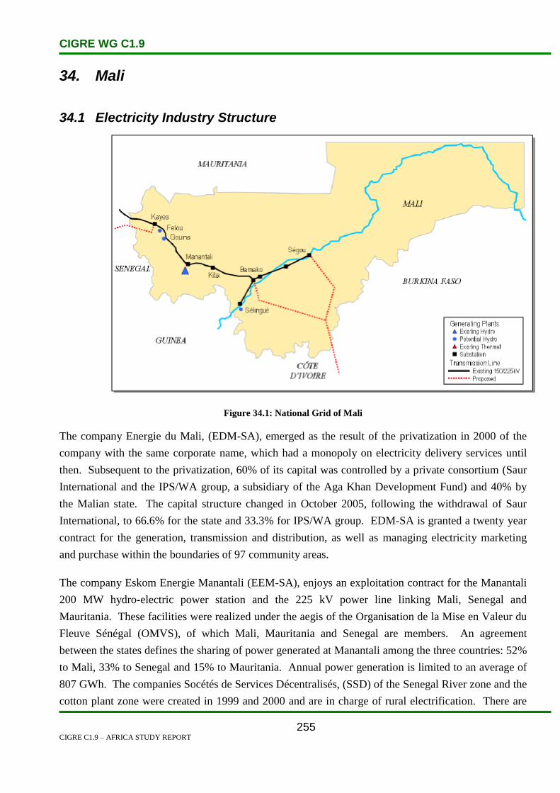
CIGRE WG C1.9
CIGRE C1.9 – AFRICA STUDY REPORT
255
34. Mali
34.1 Electricity Industry Structure
Figure 34.1: National Grid of Mali
The company Energie du Mali, (EDM-SA), emerged as the result of the privatization in 2000 of the
company with the same corporate name, which had a monopoly on electricity delivery services until
then. Subsequent to the privatization, 60% of its capital was controlled by a private consortium (Saur
International and the IPS/WA group, a subsidiary of the Aga Khan Development Fund) and 40% by
the Malian state. The capital structure changed in October 2005, following the withdrawal of Saur
International, to 66.6% for the state and 33.3% for IPS/WA group. EDM-SA is granted a twenty year
contract for the generation, transmission and distribution, as well as managing electricity marketing
and purchase within the boundaries of 97 community areas.
The company Eskom Energie Manantali (EEM-SA), enjoys an exploitation contract for the Manantali
200 MW hydro-electric power station and the 225 kV power line linking Mali, Senegal and
Mauritania. These facilities were realized under the aegis of the Organisation de la Mise en Valeur du
Fleuve Sénégal (OMVS), of which Mali, Mauritania and Senegal are members. An agreement
between the states defines the sharing of power generated at Manantali among the three countries: 52%
to Mali, 33% to Senegal and 15% to Mauritania. Annual power generation is limited to an average of
807 GWh. The companies Socétés de Services Décentralisés, (SSD) of the Senegal River zone and the
cotton plant zone were created in 1999 and 2000 and are in charge of rural electrification. There are
CIGRE WG C1.9
CIGRE C1.9 – AFRICA STUDY REPORT
256
self-producers such as the sugar refineries with 7 MW, Compagnie Malienne du Développement du
Textile (CMDT) with 8 MW and the Société Huilerie Cotonnerie du Mali (HUICOMA) with 4.5 MW
[1], [2], [3], [4].
The electrical system of Mali consists of two subsets known as operating centres which are [1, 2, 3]:
The Interconnected Network (IN) operating centre which is composed of Darsalam and
Balingué thermal generation plants of Bamako and the hydro-electric power plants of Selingue,
Sotuba and Felou. Mali’s quota in the generation from Manantali hydro-electric power plants
(owned by SOGEM-OMVS) is also injected into the interconnected network. This network
gives power to the city of Bamako which is the biggest consumer, those of Segou and Markala
(in the north-east of Bamako) and the towns of Kita, Koulikoro, Fana and Kayes in the north-
west of Bamako.
The Isolated Stations (IS), of EDM-SA consist of nineteen new community areas outside the
interconnected system, which are serviced with diesel generators or from the cross-border MV
network of Côte d’Ivoire. The major towns comprising the isolated centres are Koutiala,
Sikasso, Mopti, Gao, Tombouctou, etc.
The National Water and Energy Directorate (DNHE) is Mali’s primary governmental institution for
implementing national energy policy, regulating the energy sector and the planning of large energy and
water projects. It oversees various projects such as the National Program for the Promotion of Butane
Gas, the Special Energy Program (PSE) and the Domestic Energy Project, and supervises the
operations of a number of entities, including some of those listed in the following table (regional or
national research and development organizations are listed in the organizations section) [8].
Table 34.1 shows the government energy organizations and the activities for which they are
responsible.
Table 34.1: Government Energy Organizations – Mali
Organization Activity
National Water and Energy Directorate (DNHE),
(National Energy Directorate, energy board within the
DNHE)
Implementation and regulation of national energy
policy and planning of energy/water projects
Energy Mali (EDM) – National electricity company Production of electricity and its distribution, support for
development of new energy generation projects
National Center for Solar and Renewable Energies
(CNESOLER)
R&D and promotion of RE
National Advisory Committee for Improved Stoves (CNCFA)

CIGRE WG C1.9
CIGRE C1.9 – AFRICA STUDY REPORT
257
Table 34.1 (contd.): Government Energy Organizations – Mali
National Directorate for Rivers and Forests (DNEF), part of
the Ministry of Rural Development and the Environment
Controls exploitation of forest resources, including the
production of wood-fuel and charcoal
National Directorate of Agriculture (DNA), part of the Ministry
of Rural Development and the Environment
Biogas research and production
Planned: creation of a National Energy Committee (CNE) Facilitate knowledge exchange between global
experts and Malian interests
The Government of Mali’s energy policy aims to ensure the provision of electricity to as much of the
population as possible, and is based on:
a substantial improvement in the effectiveness and productivity of the sector,
the disengagement of the state from the operational activities of the electricity industry, and
the broadest participation and fastest distribution to the deprived sector of Mali with these
activities.
Moreover, on a regional scale, Mali is a member of the Economic Community of West African States
(ECOWAS), and has therefore participated, along with other members of ECOWAS, in the signing of
the West African Power Pool (WAPP) agreement in October 2000, which reaffirmed the decision to
develop energy production facilities and interconnect their respective electricity grids. Mali, along
with countries such as Guinea, Guinea-Bissau, Liberia, Senegal, Gambia and Cape Verde, will actively
be involved in the second phase of the WAPP agreement. Under the agreement, the WAPP is expected
to harmonize the regulatory framework that governs the electricity sector in each member country.
Mali’s electricity production in 2002 was 700 million kWh and its electricity consumption in 2002 was
651 million kWh.
Hydroelectric power is responsible for generating about 60% of electricity. Much of the remainder is
generated by oil. Two dams; the Selingue and Manantali provide 98% of the hydropower. In mid 2001,
Eskom of South Africa was awarded an $85 million contract to operate and maintain the Manantali
hydro station for 15 years. The 200 MW power station also supplies power to Senegal and Mauritania.
Hydropower only provides 1% of the energy requirement while charcoal and firewood supply 90%.
The use of charcoal as a source of energy is a main cause of deforestation, soil erosion and
desertification. EDM is responsible for generating and transmitting most of the electricity. The state
owed utility company Electricite du Mali also provides electricity. The electrification rate is 15% and
power shortages and interruptions are common [11].

CIGRE WG C1.9
CIGRE C1.9 – AFRICA STUDY REPORT
258
34.2 Load/Energy and Sales Forecasting
The level of electricity demand for Mali in 2001 was 78 MW and had extremely high growth rates in
the early years of 24% and then 6% in the rest of the planning horizon. There was a rapid rise in
expansion to 250 MW and then over 700 MW was forecast for 2020. The 24% growth rate for the
early years of expansion was a value that would require further confirmation.
Table 34.2 show the electricity demand forecast prepared in 2001.
Table 34.2: Electricity Demand Forecast
Year 2005 2010 2015 2020
Peak Demand (MW) 250 384 539 721
Two expansion scenarios are considered. The first is with 50% autonomy factors for energy trade in
MWh and trade of reserves in MW. The second scenario is one of full autonomy with energy and
power autonomy factors both set at 100%.
Table 34.3 shows the installed capacity of existing and proposed power stations [5]. Tables 34.4 and
34.5 show total electricity production and installed production capacity [6] shows electricity
consumption [7].
Table 34.3: Existing and Proposed Power Stations
Station Name Installed Capacity (MW)
Darsalam 1 10.0
Darsalam 2 20.0
Balingue 18.0
Sotuba 5.4
Selingue 44.0
Manantali 200.0
Gouina 104.0
Felou 105.0
Petit Kenie 56.0
Markala 5.2

CIGRE WG C1.9
CIGRE C1.9 – AFRICA STUDY REPORT
259
Table 34.4: Total Electricity Production
Year
Total Production
GWh
Production in
Thermal Plants
GWh
Production in
Hydro-electric
Plants – GWh
2003 820 170 650
2002 670 170 500
2001 520 170 350
2000 430 170 260
Table 34.5: Installed Production Capacity
Year Installed Capacity
MW
Installed Capacity
in Thermal Plants
MW
Installed Capacity in
Hydro-electric
Plants – MW
2005 280 130 150
2003 280 130 150
2002 250 140 110
2001 190 100 90
2000 110 60 50
Figure 34.2: Electricity Consumption in TWh
34.3 Planning and Design Criteria
The gross power generation of EDM-SA (self-generation plus purchases from SOGEM and CIE) in
2005 is established at 804.8 GWh, compared with 720.8 GWh in 2004 which is over 11.7% increase.
EDM-SA’s own generation was 403.09 GWh of which 161.37 GWH came from thermal sources and

CIGRE WG C1.9
CIGRE C1.9 – AFRICA STUDY REPORT
260
241.72 GWH from hydro-power generation. Local purchases from SOGEM (OMVS) and cross border
imports from Côte d’Ivoire were 399.80 GWh and 1.93 GWh respectively. The quota of the stations
operated by EDMSA was 50.08% of the total gross output while energy purchases amounted to
49.92%.
Figure 34.3 shows the evolution of gross generation of EDM-SA from 2002 to 2005 [1].
Figure 34.3: Gross Generation of EDM-SA
The gross generation (EDM-SA + energy purchases) of the interconnected network (IN) in 2005 was
711.1 GWh compared with 639.8 GWh in 2004, which is an 11.3 % increase. The major part of the
generation was obtained from the IN network, i.e. 88.37% of the overall gross generation.
Figure 34.4 shows the distribution of EDM-SA production by source and operation centre.
Figure 34.4: Distribution of EDM-SA Production by Source and Operation Centre

CIGRE WG C1.9
CIGRE C1.9 – AFRICA STUDY REPORT
261
The hydro-electric power stations of EDM-SA and Manantali (SOGEM) accounted for 80% of the
gross generation. The thermal stations of EDM-SA and imports from CIE (which are negligible)
accounted for the remaining 20%.
Figure 34.5 shows the distribution of gross generation by type of station.
Figure 34.5: Distribution of Gross Generation by Type of Station
34.4 Planning Approaches, Methods and Results
In 2005, the quantities of energy delivered (net generation) to the interconnected network (IN) by
EDM-SA and Manantali power plants were 706.73 GWh for a gross generation of 711.051 GWh,
which is a 99.39% efficiency in the generation segment. This efficiency rose by 0.15 points compared
with 99.24% in 2004. The energy distributed from the interconnected network is established at 690.44
GWh in 2005 compared with 619.82 GWh in 2004. On the other hand, the efficiency of the
transmission system fell slightly from 97.71% in 2004 to 97.69% in 2005. The efficiency of the
distribution system grew by 1.55% from 76.88% in 2004 to 78.43% in 2005. The global efficiency of
the interconnected network improved by 1.63% in the course of the year 2005 compared with 2004. It
rose from 74.56% to 76.19%. Performance at the isolated satellite processing centres rose slightly
from 79.0% in 2004 to 79.4% in 2005. The global efficiency of EDM-SA in 2005 is established at
76.6% against 75.1% in 2004, i.e. a 1.5% gain. Even though the trend in the overall efficiency of
EDM-SA was positive, the level of total losses is still high, above the contract value of 14% [1].
The efficiency of the interconnected network of EDM-SA is presented in Table 34.6 below:

CIGRE WG C1.9
CIGRE C1.9 – AFRICA STUDY REPORT
262
Table 34.6: Efficiency of the Interconnected Network
2004 2005
Overall gross generation of IN (GWh) 639.146 711.051
Net generation of IN (GWh) 634.346 706.731
Energy delivered to distribution network of IN (GWh) 619.829 690.439
Energy sold on the IN (GWh) 476.580 541.813
34.5 Specific Technical Issues
Mali has some good potential opportunities for using renewable and environmentally sound energy
technologies for energy service provision in rural areas. A low overall level of electrification, an
established renewable energy sector and reforming government are all factors which favour such an
approach. The threats to successful deployment include a continuing shaky economy and the limited
ability of rural populations to pay for improved energy services. The energy sector is mostly based on
traditional fuels, with a low per capita consumption (0.3 tons oil equivalent). 90% of energy consumed
comes from the unsustainable use of wood fuel. Biomass producing surface has been disappearing at a
rate of 9 000 ha per year, leading to soil erosion and desertification, and making this the predominant
environmental issue linked to energy consumption. A number of renewable energy (RE) programmes,
mostly photovoltaic (PV), have been deployed in the country to date. Current efforts focus on
promoting promising PV applications whilst continuing development of other technologies such as
solar dryers, micro hydro, wind power, small scale gasifiers and biogas digesters. Meanwhile, the
government is encouraging private enterprises to take the lead on renewable energy commercialization
issues such as distribution, installation, and maintenance of installed systems [8].
High degrees of solar radiation suggest potential in the PV sector, which is only being exploited on a
small scale at present. Also, although electricity is mostly produced from hydro, there is still a huge
potential of hydro power available (some 1 050 GWh). Mali plans to produce 15% of its total energy
in the form of renewable energy by 2020. The Action Plan for Renewable Energy Promotion in Mali
was established to achieve the renewable energy target of increasing the share of renewables in TPES
from less than 1% in 2002 to 15% in 2020. Their energy policy is defined by 5 major objectives: [9]
improving access to energy, especially from renewables.
the rational use of existing energy sources.
the efficient use of existing natural resources to produce energy.
sustainable use of biomass resources through the conservation and protection of forests.
strengthening government capacity and streamlining administrative procedures within the
energy sector.

CIGRE WG C1.9
CIGRE C1.9 – AFRICA STUDY REPORT
263
34.6 Financial Issues
South Africa’s Eskom Enterprises won a US$ 85 million contract in mid 2001 to operate and maintain
the newly constructed Manantali hydro station for 15 years. The 200 MW power station supplies
power to Mali, Senegal and Mauritania [2].
On 18 June 2009 the World Bank’s Executive Board approved an International Development
Association (IDA) credit in the amount of US$120 million for the Mali Energy Support Project to
improve access and efficiency of electricity services in Bamako, the capital city, and in targeted rural
areas [10].
This financing aims mainly to upgrade transmission and distribution networks of Energie du Mali
Société Anonyme (EDM-SA), the water and electricity utility. Such upgrades will enable Mali to fully
utilize additional thermal capacity under construction and expected gas generated power from Côte
d’Ivoire and Ghana. The project will advance the Government of Mali’s effort to expand access, as
electricity services will be provided to growth centers that currently receive inadequate or no grid
supply.
The project has three components:
Component 1:
Transmission and distribution reinforcement and extension (US$107.0 million). This component is
mainly intended to finance: [10]
the rehabilitation of the 150 kV transmission line between Ségou (central part of the country)
and Bamako to allow a reliable transit of high voltage power to the capital city;
the construction of a 150 kV ring around Bamako to improve reliability of electricity supply to
the Bamako area ;
the rehabilitation and extension of the distribution networks in Bamako to provide electricity
access to growing areas of the city;
the expansion of grid access in main secondary towns (Kayes, Sikasso, Koutiala, Kati, and
Mopti) and in the Niger River Irrigation Office area, particularly in the localities of Siribala,
Dougabougou, Sansanding, Molodo and Dioro;
the connection to the main grid of the localities of Ouléssébougou and Kangaba, currently
supplied by isolated diesel units.

CIGRE WG C1.9
CIGRE C1.9 – AFRICA STUDY REPORT
264
Component 2:
Energy efficiency and demand side management (US$ 5.0 million). The key objective of this
component is to address the country’s energy security needs through the implementation of energy
efficiency measures across various supply and demand side sectors. The implementation of this
initiative is expected to reduce energy consumption and peak load demand, bringing direct benefits to
households and other consumers (through lowered electricity bills) and the government (through
deferred investment in electricity generation for new capacity and enhanced energy security).
Furthermore, actions implemented under this initiative are expected to reduce local pollution and
global GHG emissions.
Component 3:
Capacity and institutional strengthening of key sector institutions (US$8.0 million). Experience in the
area of energy sector reform over the last five years indicates that more work is needed to strengthen
the institutional, legal and regulatory environment and governance to foster an open and predictable
business environment attractive to private investors and operators. This component is intended mainly
to help restructuring efforts of EDM-SA by setting a minimum platform of technical and financial
performance targets with monitoring indicators.
34.7 Human Resource Issues
Eskom Energy Manantali is a subsidiary of Eskom Enterprises which is a member of Eskom Holdings
South Africa. It draws its manpower from Eskom and member states, that is, Mali, Mauritania and
Senegal [4]. Energie du Mali manpower is composed mainly of Mali professionals since it is state
owned.
34.8 References
1. 2005 Performance indicators of WAPP member utilities power systems; May 2007.
2. http://www.mbendi.co.za/indy/powr/af/ml/p0005.htm
3. http://www.energyrecipes.org/reports/genericData/Africa/061129%20RECIPES%20countr
y%20info%20Mali.pdf
4. http://www.globalregulatorynetwork.org/Resources/2ndGRN/Images/Session%202%20-
%20Tshibingu.pdf
5. http://www.purdue.edu/discoverypark/energy/pdfs/wafrica/Mali.pdf
6. http://www.iaea.org/inisnkm/nkm/aws/eedrb/data/ML-elic.html
7. http://www.indexmundi.com/g/g.aspx?c=ml&v=81
8. http://www.areed.org/country/mali/mali.pdf

CIGRE WG C1.9
CIGRE C1.9 – AFRICA STUDY REPORT
265
9. http://www.energyrecipes.org/reports/genericData/Africa/061129%20RECIPES%20country%20info%20
Mali.pdf
10. http://web.worldbank.org/WBSITE/EXTERNAL/NEWS/0,,contentMDK:22218084~menu
PK:51062075~pagePK:34370~piPK:34424~theSitePK:4607,00.html
11. http://www.estandardsforum.org

CIGRE WG C1.9
CIGRE C1.9 – AFRICA STUDY REPORT
266
35. Mauritania
35.1 Electricity Industry Structure
Before the year 2000 parastatal utility, the National Company of Water and Electricity or Société
Nationale d’Eau et d’Electricité (SONELEC), was responsible for the supply of electrical power and
water in Mauritania. The company had become privatized in 2000 and this resulted in the formation of
two new private companies being responsible for the supply of water and electricity separately. The
National Water Company (SNDE) dealt with the water supply of the country and the Mauritanian
Electricity Company/Société Mauritanienne de d’Electricité (SOMELEC) became solely responsible
for the supplying electrical power.
In line with Mauritania’s liberal economic reforms, the formation of SOMELEC allowed for more
investment and continual budgetary support, improving the electrical power supply and expanding the
electrical power distribution network in the country. Since SOMELEC’S privatization, Mauritania’s
electrical power generation has been heavily dependent on thermal power plants, but increased
investment has resulted in new technological knowledge and project initiatives being brought into the
country.
With this in mind, SOMELEC has aimed to significantly increase the distribution rate in towns with
existing networks by improving security conditions and setting prices compatible with household
purchasing power. The company has also planned to bring electricity to urban and rural areas that have
not been connected in its national grid. Falling in line with these aims, SOMELEC’S specific
objectives for the five-year period from 2003 to 2008 is to extend electricity supply networks to many
new regions in urban, semi-urban or rural areas, and to increase the effectiveness of various production
units including those at Nouakchott and Atar.
Mauritania has also been receiving electrical power from Mali through recent hydropower
developments, due to a power sharing agreement between the two countries.
Hydropower generates 12.5% of electricity and oil and diesel the remainder. Electricity is provided,
distributed and transmitted by Société Mauritanienne de l’électricité (Somelec), which is a state owned
company. The electric grid is in poor shape. The World Bank is providing financing to improve and
upgrade the network. As of 2004, just 24% of households were hooked up to the electrical grid.

CIGRE WG C1.9
CIGRE C1.9 – AFRICA STUDY REPORT
267
Figure 35.1: Electricity production between 2000-2011
Figure 35.2: Electricity consumption between 2000-2011
35.2 Planning and Design Criteria
The Manatali hydropower project was completed in 2003. The project consisted of a 200-MW power
station and an 800-mile (1 300 km) network of transmission lines to the capitals of Mali (Bamako),
GWh
GWh

CIGRE WG C1.9
CIGRE C1.9 – AFRICA STUDY REPORT
268
Mauritania (Nouakchott) and Senegal (Dakar). This development initiative supplies electricity to the
grids of Mali, Mauritania, as well as Senegal.
The project has also allowed for the construction of a single-circuit, 100 km long, transmission line
connecting Kaedi to Boghe, and having an exchange capacity of 24 MW. This included the expansion
of the 90 kV Kaedi substation, the supply and installation of the overhead lines, cables, switchgear,
protection and control equipment. All of which was necessary to reinforce the system and connect the
substations at Kaedi, Boghe and Rosso with the corresponding 15 kV SOMELEC power generating
stations in these three towns in Mauritania. [1]
35.3 Load and Energy Forecasting
Electricity output has risen rapidly in recent years, climbing by 40.2% between 2006 and 2010.
National installed capacity was 105,000 kW in 2001. Production increased from 49.9 million kWh in
1969 to 154 million kWh in 2000, with 84.4% from fossil fuels and 15.6% from hydropower.
Consumption of electricity in 2000 was 143.2 million kWh.
Mauritania gains a portion of its power from dams built on the Senegal River in a joint venture with
Senegal and Mali. In 1999, 99% of Mauritania's primary energy came from oil. Currently 38.94% of
total electricity installed capacity is Hydroelectric.
35.4 Planning and Design Criteria
No discussion on planning and design criteria issues was presented.
35.5 Planning Approaches and Methods
No discussion on planning approaches and methods issues was presented.
35.6 Specific Technical Issues
No discussion on specific technical issues was presented.
35.7 Financing Issues
Half the population still depends on agriculture and livestock for a livelihood, even though many of the
nomads and subsistence farmers were forced into the cities by recurrent droughts in the 1970s and
1980s. Mauritania has extensive deposits of iron ore, which account for nearly 40% of total exports.
The nation's coastal waters are among the richest fishing areas in the world but overexploitation by
foreigners threatens this key source of revenue. The country''s first deepwater port opened near
Nouakchott in 1986. Before 2000, drought and economic mismanagement resulted in a buildup of
CIGRE WG C1.9
CIGRE C1.9 – AFRICA STUDY REPORT
269
foreign debt. In February 2000, Mauritania qualified for debt relief under the Heavily Indebted Poor
Countries (HIPC) initiative and nearly all of its foreign debt has since been forgiven. A new
investment code approved in December 2001 improved the opportunities for direct foreign investment.
Mauritania and the IMF agreed to a three-year Poverty Reduction and Growth Facility (PRGF)
arrangement in 2006. Mauritania made satisfactory progress, but the IMF, World Bank, and other
international actors suspended assistance and investment in Mauritania after the August 2008 coup.
Since the presidential election in July 2009, donors have resumed assistance. Oil prospects, while
initially promising, have largely failed to materialize, and the government has placed a priority on
attracting private investment to spur economic growth. The Government also emphasizes reduction of
poverty, improvement of health and education, and privatization of the economy. Economic growth
remained above 5% in 2010-11, mostly because of rising prices of gold, copper, iron ore, and oil.
35.8 Human Resources
No discussion on specific technical issues was presented.
35.9 References
1. www.mbendi.com
2. CIA World Factbook
3. http://www.energyrecipes.org/reports/genericData/Africa/061129%20RECIPES%20country%2
0info%20Mauritania.pdf
4. https://www.cia.gov/library/publications/the-world-factbook/geos/mr.html#top

CIGRE WG C1.9
CIGRE C1.9 – AFRICA STUDY REPORT
270
36. Mauritius
36.1 Electricity Industry Structure
The Republic of Mauritius consists of a main island, Mauritius, and a group of smaller islands in the
Indian Ocean. It is approximately 1 500 km east of Madagascar, some 2 000 km from South Africa,
6 000 km from Australia and some10 000 km from Europe. The total land area is 2 040 km2.
The population of the Republic of Mauritius is estimated to be 1.3 million. Mauritius is one of the
Southern African Development Community (SADC) countries, and a member of the Common Market
of Eastern and Southern Africa (COMESA).
The Central Electricity Board (CEB) is a parastatal body, responsible for generation, transmission,
distribution and sale of electricity in Mauritius. CEB provides a service to some 357 000 customers
ranging from small households to large industries and enterprises. The utility prepares and carries out
development schemes with the general objective of promoting, co-ordinating and improving the
generation, transmission, distribution and sale of electricity in Mauritius.
The CEB produces around 60% of the country’s total power requirements, and the remaining 40% is
purchased from independent power producers (IPPs) and co-generators. Currently, CEB is the only
organization responsible for the transmission, distribution and supply of electricity to the island’s
1.3 million inhabitants.

CIGRE WG C1.9
CIGRE C1.9 – AFRICA STUDY REPORT
271
Figure 36.1: Electricity Supply Industry Structure in Mauritius
Figure 36.2: Electricity Sales vs. GDP in Mauritius
The electricity sales have grown by
625% in the years from 1976, while
GDP has grown by less than half that
amount, 275%, over the same period.

CIGRE WG C1.9
CIGRE C1.9 – AFRICA STUDY REPORT
272
The government of Mauritius committed itself in October 2001 to:
Restructure the electricity sector by corporatizing the CEB as a vertically-integrated utility
(VIU),
Setting up an independent, multi-sectoral regulator for the electricity industry and,
Inviting a strategic partner to assist in the management of the CEB.
36.2 Load and Energy Forecasting
The energy demand forecast is prepared using a bottom-up approach, starting from a forecast of energy
sales on a sector-by-sector basis. The sales forecast, network losses and the energy consumed by the
system was added to obtain the gross energy generation needs, i.e.
Gross Energy Generation Requirements = Energy Sales + Network Losses + Power Station Auxiliary
Consumption
Low, probable, and high scenarios were established using three scenarios for growth rates. This
methodology was adopted over one based on a relationship with GDP, since economic growth in
Mauritius is still developmental and heavily influenced by public policy.
The forecast of capacity requirements to meet peak demand, for low, probable, and high scenarios, is
derived using an empirical relationship with total energy sent out for the respective cases, i.e.:
P = a + bE + cE1/2
Where:
P = peak power sent out for the year (MW);
E = total energy sent out during the year (GWh);
a, b, and c are regression coefficients derived from historical data.
Table 36.1: Probable Sales Forecast by Customer Segment

CIGRE WG C1.9
CIGRE C1.9 – AFRICA STUDY REPORT
273
The forecast electricity sales by customer category is shown in Figure 36.3
Figure 36.3: Probable Forecast of Electricity Sales by Customer Segment in Mauritius
The forecast peak electricity demand and energy forecasts are shown in Figures 36.4 and 36.5
respectively.
Figure 36.4: Peak Demand Forecast MW in Mauritius
Under the probable forecast,
capacity requirements to
meet peak demand will
grow from 319 MW in 2002
to 484 MW in 2012.
This represents an average
increase of 17 MW per year
over the next ten years, or an
average cumulative annual
increase 4.3%.

CIGRE WG C1.9
CIGRE C1.9 – AFRICA STUDY REPORT
274
Figure 36.5: Energy Forecast GWh in Mauritius
36.3 Planning and Design Criteria
CEB has planned its power generation requirements so that sufficient power generating capacity is
available to meet peak demand under an N-2 condition, i.e. assuming the largest generating unit in the
system is unavailable due to regularly scheduled maintenance and, at the same time, the next largest
generating unit unexpectedly fails, or vice versa.
CEB plans to have reserve margins in the range of 20% to 25% of total effective generating capacity.
In planning and designing the transmission system, CEB apply the N-1 minimum standard security
criterion. That means, the transmission system must remain intact and capable of transmitting the
system peak demand to the 22 kV bus bars when any one circuit and/or one 66/22 kV transformer is
out of service due to a fault or for maintenance.
CEB has adopted voltage regulation performance in the range ± 6 per cent, to give a margin within the
statutory requirement to maintain voltages at the nominal level.
Under the probable forecast,
Energy generation
requirements will increase
from 1 715 GWh in 2002 to 2
727 GWh in 2012.
This is equivalent to an
average cumulative annual
growth rate of 4.8% over the
ten-year planning horizon

CIGRE WG C1.9
CIGRE C1.9 – AFRICA STUDY REPORT
275
Hydro
6%
Coal
26%
Bagasse
16%
Fuel oil
49%
Kerosene
3%
Hydro Coal Bagasse Fuel oil Kerosene
Installed Capacity: 367 MW (2005)
Figure 36.6: Generation Mix in Mauritius
36.4 Planning Approaches and Methods
CEB has developed an integrated electricity plan (IEP) in a manner consistent with established energy
and capacity reserve criteria suited to small island nations. These are static, deterministic reserve
criteria and, because Mauritius is an island without interconnection to sources of supply from
neighbouring jurisdictions, these are higher than the reserves that would need to be held in other
countries.

CIGRE WG C1.9
CIGRE C1.9 – AFRICA STUDY REPORT
276
Figure 36.7: The Generation and Transmission Network of Mauritius
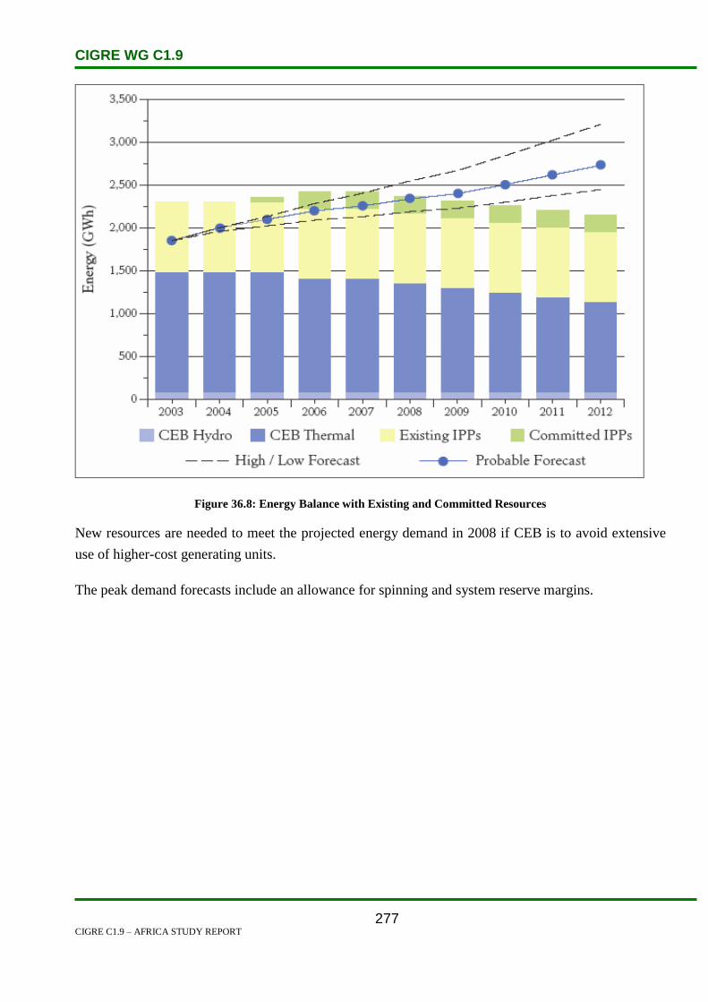
CIGRE WG C1.9
CIGRE C1.9 – AFRICA STUDY REPORT
277
Figure 36.8: Energy Balance with Existing and Committed Resources
New resources are needed to meet the projected energy demand in 2008 if CEB is to avoid extensive
use of higher-cost generating units.
The peak demand forecasts include an allowance for spinning and system reserve margins.

CIGRE WG C1.9
CIGRE C1.9 – AFRICA STUDY REPORT
278
Figure 36.9: Effective Capacity Balance with Existing and Committed Resources
The probable generation expansion plan is shown in Table 36.2.
Table 36.2: The Probable Generation Expansion Plan
Year
Probable
MW
Low Demand
MW
High Demand
MW
2006 64 32 64
2007 0 32 32
2008 32 0 32
2009 0 32 32
2010 32 0 50
2011 50 32 50
2012 50 0 50
Total 228 128 310

CIGRE WG C1.9
CIGRE C1.9 – AFRICA STUDY REPORT
279
Figure 36.10: 10-Year Outlook for New Generation Resources
36.5 Specific Technical Issues
To contain fault levels, air-cored reactors have been used in series with transmission lines, and neutral
earthing resistances are used for power transformers and alternators. In one particular case, network
reconfiguration has been applied.
CEB personnel have little exposure to experiences or practices of developed countries.
No FACTS devices have been introduced into the system because it is small with relatively short lines
of 30 km maximum.
Introduction of new technologies would need to be assessed for specific applications and the cost-
benefit analysis should be evaluated.
It is envisaged that operation and maintenance issues would imply a reduction in outage time with
emphasis towards increased live line maintenance practice on the MV and LV networks. Moreover,
quicker restoration time would involve increasing use of more on-line monitoring of network operating

CIGRE WG C1.9
CIGRE C1.9 – AFRICA STUDY REPORT
280
states and some degree of automation of the switching points in the distribution network. As the
system expands, these issues would become more pressing.
Inherently the (N-1) security criterion is used in planning the network such that no single element
failure will result in loss of supply. This ensures a fundamental measure against system collapse.
There is no defined methodology to evaluate the costs of a blackout, but it is recognized that such an
event represents a major loss in economic activities for the country and a reduction in sales revenue for
the utility.
Presently, power system analysis software is the main tool used to simulate contingencies and to take
measures to remedy such system weaknesses. CEB is now re-structuring its organizational processes
to address these issues and a request for proposals for consultancy services to conduct a power system
study has been launched recently.
The system is too small to contemplate system islanding although the power stations have the
capability to switch to islanding mode. Currently, the practice has been to implement an automatic
load shedding scheme in case of the loss of a major generation group for which spinning reserve
margin is not sufficient at that instant.
The system consists of single bus-bar substations with bus couplers, linked by double circuit overhead
lines in a meshed configuration. The bus couplers are normally closed. Details of the system are
described in our Integrated Electricity Plan available at www.ceb.intnet.mu.
In the past many cogeneration plants at sugar mills were connected to the 22 kV distribution network.
With the centralization of the sugar industry this has been reduced to one plant only. Normally, the
network infrastructure requirements are only assessed and planned after the project is submitted by the
proposer and approved.
As part of its country assistance programme, UNDP has launched a request for proposals for
consultancy services to develop a Grid Code for integrating distributed renewable energy sources
particularly on the low-voltage networks. In this respect, issues such as safety, protection, power
quality and others would be addressed by the Grid Code.
Voltage stability is not an issue in the CEB’s system as the generation plants are evenly located around
the island and transmission of power is not done over long distances.
Reactive power forecasting is based on analysis carried out on actual load flows and it is also related to
the active power demand forecast.

CIGRE WG C1.9
CIGRE C1.9 – AFRICA STUDY REPORT
281
Load models are voltage dependent and the values of active and reactive powers are taken from the
actual SCADA recordings. Reactive power compensation is done by the automatic switching of
capacitor banks located at the 22 kV bus-bars in the main bulk supply substations.
36.6 Financing Issues
The Mauritius electricity projects are funded by:
The Government of Mauritius,
World Bank, and
International development agencies.
36.7 Human Resources
No discussion on human resource issues was presented.
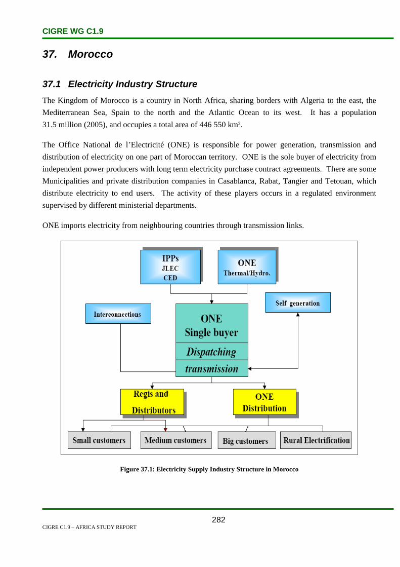
CIGRE WG C1.9
CIGRE C1.9 – AFRICA STUDY REPORT
282
37. Morocco
37.1 Electricity Industry Structure
The Kingdom of Morocco is a country in North Africa, sharing borders with Algeria to the east, the
Mediterranean Sea, Spain to the north and the Atlantic Ocean to its west. It has a population
31.5 million (2005), and occupies a total area of 446 550 km².
The Office National de l’Electricité (ONE) is responsible for power generation, transmission and
distribution of electricity on one part of Moroccan territory. ONE is the sole buyer of electricity from
independent power producers with long term electricity purchase contract agreements. There are some
Municipalities and private distribution companies in Casablanca, Rabat, Tangier and Tetouan, which
distribute electricity to end users. The activity of these players occurs in a regulated environment
supervised by different ministerial departments.
ONE imports electricity from neighbouring countries through transmission links.
Figure 37.1: Electricity Supply Industry Structure in Morocco

CIGRE WG C1.9
CIGRE C1.9 – AFRICA STUDY REPORT
283
Figure 37.2: Future Electricity Market in Morocco
Statistical data for the Morocco electricity system are shown in Table 37.1:
Table 37.1: Statistical Data for Morocco – 2008
Installed Capacity by Type of Generation (MW) – 2008
Thermal 3 380
Steam Turbines 2 385
Gas Turbines 615
Combined Cycle 380
Diesel 69
Hydro 1 729
Renewables 114
Others
Total 5 292

CIGRE WG C1.9
CIGRE C1.9 – AFRICA STUDY REPORT
284
Table 37.1 (contd.): Statistical Data for Morocco – 2008
Yearly Generation by Type (GWh) – 2008
Thermal 18 591
Steam Turbines 14 985
Gas Turbines 739
Combined Cycle 2 867
Diesel 58
Hydro 1 360
Renewables 298
Others
Total 20 307
Yearly Consumption (GWh)
Residential 3 196
Commercial 1170
Industrial 5375
Others 1 1970
Total 21 711
Consumption per Capita (kWh) 697
Population supplied (%) 95
Population growth (%) 1.1
Population 2008 (000) 31 170
Maximum Load (MW)
Growth rate (%) 5.00
Time 21:45
Date 1 Jul 08
2008 4180
2007 3980
Exports (GWh) 149
imports (GWh) 4411
Electricity Losses (%)
Total n:d
Distribution n:d
Transmission 4.7
Generation n:d

CIGRE WG C1.9
CIGRE C1.9 – AFRICA STUDY REPORT
285
Table 37.1 (contd.): Statistical Data for Morocco – 2008
Transmission Lines (Km)
400–500 kV 1 284
220–230 kV 7 607
132–150 kV 144
Substation Capacities (MVA)
400–500 kV 2 840
220–230 kV 11 570
132–150 kV 610
37.2 Load and Energy Forecasting
Energy demand in 2004 was 17 945 GWh, versus 16 779 GWh in 2003. This represents a growth rate
of 7%.
Maximum demand grew in 2004 by 7.2% compared to 2003, from 3 191 MW to 3 421 MW. At the
end of 2004, the total installed capacity amounted to 4 621 MW.
Figure 37.3: Electricity Sales GWh in Morocco

CIGRE WG C1.9
CIGRE C1.9 – AFRICA STUDY REPORT
286
Figure 37.4: Number of Customers in Morocco
Table 37.2: Demand and Generation Forecast in Morocco
Electricity Forecast
2018 Demand Max (MW) 7 362
Generation (GWh) 4 4002
2013 Demand Max (MW) 5 255
Generation (GWh) 31 373
2009 Demand Max (MW) 4 089
Generation (GWh) 24 693
37.3 Planning and Design Criteria
Figure 37.5: Energy by Category in Morocco
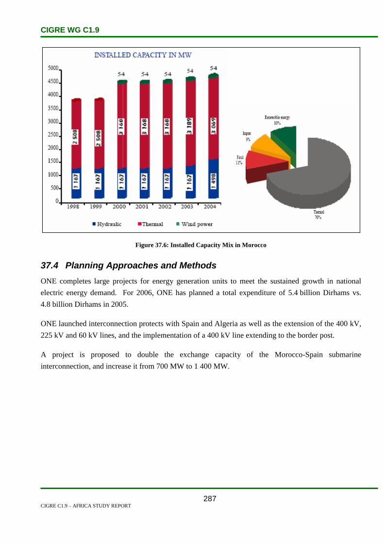
CIGRE WG C1.9
CIGRE C1.9 – AFRICA STUDY REPORT
287
Figure 37.6: Installed Capacity Mix in Morocco
37.4 Planning Approaches and Methods
ONE completes large projects for energy generation units to meet the sustained growth in national
electric energy demand. For 2006, ONE has planned a total expenditure of 5.4 billion Dirhams vs.
4.8 billion Dirhams in 2005.
ONE launched interconnection protects with Spain and Algeria as well as the extension of the 400 kV,
225 kV and 60 kV lines, and the implementation of a 400 kV line extending to the border post.
A project is proposed to double the exchange capacity of the Morocco-Spain submarine
interconnection, and increase it from 700 MW to 1 400 MW.

CIGRE WG C1.9
CIGRE C1.9 – AFRICA STUDY REPORT
288
Table 37.3: Morocco Generation Projects
The main technical criteria for transmission system development is the N-1 security criterion, which is
applied everywhere. It refers to the loss of single circuit, transformer or generator, when after the
occurrence of a fault event the following consequences are to be avoided:
thermal overloading of branches,
voltage deviations above permitted range,
loss of stability,
loss of load,
interruption of power transits, and
disturbance spreading over power system.
The N-2 criterion is not applied.
With regard to the security margins, some restrictions are imposed on the generating unit capability
limits, specifically on the Qmax and Qmin limits.
With regard to the capability of lines and transformers, the operational planning units in the national
dispatching centres usually do not define different thermal ratings for winter and summer operational
conditions, as happens in Europe, but rather for normal and emergency conditions. Moreover,
different ratings are defined based on the age of equipment.

CIGRE WG C1.9
CIGRE C1.9 – AFRICA STUDY REPORT
289
For reliability analysis probabilistic approaches or the assessment of the probability of N-1 events
during transmission system planning are not considered. Methods used by transmission planners are
based on the deterministic approach and the probabilities of the occurrence of the various events
(network failures, generator dispatch, circuit availability, etc.) are not taken into consideration. Such
approaches can be found only in some studies performed by foreign consulting companies.
Morocco performs load flow computations, static security analysis, short circuit calculations and
system stability analysis during the planning process. Uncertainties are mostly taken into account using
multi-scenario analyses. The most important uncertainties are:
the size and location of new power plants,
generator availability,
load forecasts, and
country power balance.
The North African power utilities do not have any specific construction criteria for interconnection
lines, but commissioning of an interconnection requires a higher hierarchical level of analysis where
possible incoherency in planning criteria and system constraints are solved, as well as all aspects
related to the engineering issues and co-ordination (e.g.: protection philosophy and relay settings).
Considering the complexity of interconnection studies, the pre-feasibility and feasibility studies for the
different kinds of interconnections (HVAC, HVDC) are frequently performed by foreign consulting
companies. The specific economic criteria for interconnection lines are based on difference in
electricity prices or on the overall change in system operational costs derived by different
interconnection options and different operating regimes of power systems.
N Security Conditions
The basic assumptions related to the N criterion of the transmission network are:
The rating limits of transmission lines should be intended as maximum permanent currents.
In normal operating conditions, no overload of the transmission network is allowed.
No generator will be above its continuous reactive capability with possible restrictions decided
by the planner to account for operational constraints.
The loads are represented as constant active and reactive powers.
In normal operating conditions a long-term overload of transformers up to 10% of nominal
rating is allowed. A short term overload (less than 15 minutes) is allowed up to 20%.

CIGRE WG C1.9
CIGRE C1.9 – AFRICA STUDY REPORT
290
For the transmission system generally, unless otherwise specified, the maximum operating voltages are
as follows:
For 400 kV network maximum voltage is 420 kV.
For 220 kV network maximum voltage is 231 kV.
For 150 kV network maximum voltage is 158 kV.
For 132 kV network maximum voltage is 139 kV.
For 90 kV network maximum voltage is 95 kV.
For 66 kV network maximum voltage is 72.6 kV.
The minimum operating voltages values are as follows:
For 400 kV network minimum voltage is 374.8 kV.
For 220 kV network minimum voltage is 209 kV.
For 150 kV network minimum voltage is 142 kV.
For 132 kV network minimum voltage is 125 kV.
For 90 kV network minimum voltage is 85 kV.
For 66 kV network minimum voltage is 59.4 kV.
Operating Frequency:
The nominal frequency is 50 Hz and its permissible variation range under AGC is 50 ± 0.05 Hz.
Under normal operating condition the maximum permissible variation range is 50 ± 0.2 Hz.
N-1 Security Conditions
The following criteria are applied under N-1 contingency conditions:
The transmission system should be planned such that reasonable and foreseeable contingencies
do not result in the loss or unintentional separation of a major portion of the network or in the
separation from the regional interconnected system.
During contingency conditions, a temporary overload of the transmission lines is allowed up to
10%.
A temporary overload of transformers is allowed in emergency conditions up to 20% during
peak hours.
The maximum post-transient voltage deviation is 10%.
For transmission system generally, unless otherwise specified, the maximum operating voltage values
are as follows:
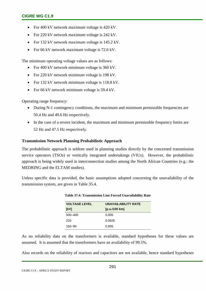
CIGRE WG C1.9
CIGRE C1.9 – AFRICA STUDY REPORT
291
For 400 kV network maximum voltage is 420 kV.
For 220 kV network maximum voltage is 242 kV.
For 132 kV network maximum voltage is 145.2 kV.
For 66 kV network maximum voltage is 72.6 kV.
The minimum operating voltage values are as follows:
For 400 kV network minimum voltage is 360 kV.
For 220 kV network minimum voltage is 198 kV.
For 132 kV network minimum voltage is 118.8 kV.
For 66 kV network minimum voltage is 59.4 kV.
Operating range frequency:
During N-1 contingency conditions, the maximum and minimum permissible frequencies are
50.4 Hz and 49.6 Hz respectively.
In the case of a severe incident, the maximum and minimum permissible frequency limits are
52 Hz and 47.5 Hz respectively.
Transmission Network Planning Probabilistic Approach
The probabilistic approach is seldom used in planning studies directly by the concerned transmission
service operators (TSOs) or vertically integrated undertakings (VIUs). However, the probabilistic
approach is being widely used in interconnection studies among the North African Countries (e.g.: the
MEDRING and the ELTAM studies).
Unless specific data is provided, the basic assumptions adopted concerning the unavailability of the
transmission system, are given in Table 35.4.
Table 37.4: Transmission Line Forced Unavailability Rate
VOLTAGE LEVEL
[kV]
UNAVAILABILITY RATE
[p.u./100 km]
500–400 0.005
220 0.0025
150–90 0.005
As no reliability data on the transformers is available, standard hypotheses for these values are
assumed. It is assumed that the transformers have an availability of 99.5%.
Also records on the reliability of reactors and capacitors are not available, hence standard hypotheses
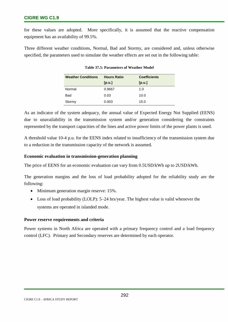
CIGRE WG C1.9
CIGRE C1.9 – AFRICA STUDY REPORT
292
for these values are adopted. More specifically, it is assumed that the reactive compensation
equipment has an availability of 99.5%.
Three different weather conditions, Normal, Bad and Stormy, are considered and, unless otherwise
specified, the parameters used to simulate the weather effects are set out in the following table:
Table 37.5: Parameters of Weather Model
Weather Conditions Hours Ratio
[p.u.]
Coefficients
[p.u.]
Normal 0.9667 1.0
Bad 0.03 10.0
Stormy 0.003 15.0
As an indicator of the system adequacy, the annual value of Expected Energy Not Supplied (EENS)
due to unavailability in the transmission system and/or generation considering the constraints
represented by the transport capacities of the lines and active power limits of the power plants is used.
A threshold value 10-4 p.u. for the EENS index related to insufficiency of the transmission system due
to a reduction in the transmission capacity of the network is assumed.
Economic evaluation in transmission-generation planning
The price of EENS for an economic evaluation can vary from 0.5USD/kWh up to 2USD/kWh.
The generation margins and the loss of load probability adopted for the reliability study are the
following:
Minimum generation margin reserve: 15%.
Loss of load probability (LOLP): 5–24 hrs/year. The highest value is valid whenever the
systems are operated in islanded mode.
Power reserve requirements and criteria
Power systems in North Africa are operated with a primary frequency control and a load frequency
control (LFC). Primary and Secondary reserves are determined by each operator.

CIGRE WG C1.9
CIGRE C1.9 – AFRICA STUDY REPORT
293
The frequency and active power control is provided by the following means:
Automatic response from generating units operating in a free governor frequency sensitive
mode (Primary Reserve).
Automatic Generation Control (AGC) of generating units equipped with automatic load
frequency control (Secondary Reserve).
37.5 Specific Technical Issues
An increase in population and economic development has caused an increase in demand for electricity.
Morocco relies heavily on imported sources of energy to meet its energy needs. The country is part of
an interconnection programme with Algeria and Spain, whereby electricity is imported from its two
partners. Morocco imports coal from the United States, Colombia, and South Africa. The coal is used
to power the country’s two largest electrical power stations at Mohammedia and Jorf Lasfar. There
does exist at present a small coal mine at Jerada, but coal reserves at the mine have been declining.
Morocco is in the process of gradually integrating its electrical power grid with those of neighbouring
African and European countries. In May 2003 Tunisia, Algeria, and Morocco expressed their interest
in linking their electricity systems to the EU single energy market. In April 2004 an effort was made to
expand the capacity of the interconnection between Spain and Morocco by 700 MW, resulting in the
total capacity reaching 1 400 MW.
The Spanish energy company, Endesa, together with Morocco’s power utility, ONE have completed
the construction of a 384-MW combined cycle power station in Tahaddart. Operations at the power
station came on line in January 2005.
ONE has initiated a project to construct the Al Wahda thermal power station with combined cycle.
From a power of 2 X.400 MW, the Al Wahda power station will consume 1.1 billion Nm3 of natural
gas and its annual production in electric power, being 6 billion kWh, will account for 23% of
Morocco’s total electrical power generation by 2010.
Morocco is also focusing on making use of wind power to generate electricity. With this in mind, ONE
has launched a wind park project at Cape Sim in the area of southern Essaouira. It is capable of
producing 60 MW of electricity based on wind power producing an annual average of 210 GWh. This
is to commence in 2006. ONE has launched another wind park project in the area south east of
Tangier, capable of producing 140 MW of electricity, and producing an annual average of 510
GWh.[1]

CIGRE WG C1.9
CIGRE C1.9 – AFRICA STUDY REPORT
294
37.6 Financing Issues
Transmission investments are mostly financed through transmission fees, loans, internal sources and
very few by private investors.
Economic criteria (capital investment, IRR, NPV), in transmission network planning are applied. In
economic evaluations, the reduction in the cost of the losses is usually estimated, but additional
benefits related to the reduction of congestion costs are also taken into account, as well as the increase
of transmission service revenues.
Generally, the Transmission System Operator (TSO) has not defined the cost of EENS and the applied
values are agreed for each study among the local experts and also taking into account the experience of
the consulting companies, whenever they are involved in the execution of the transmission system
studies. Usually, the undelivered electricity costs across North Africa range between 0.5 and
2US$/kWh.
Market-oriented transmission investments (merchant lines) and investments from a regional
perspective are not applied. National transmission networks are mainly planned according to technical
considerations and economic rationalization of new investments.
37.7 Human Resources
Since early 2000’s the gross enrollment rates have been rising steadily for all levels of education.
Completion rates at the primary level have increased from 57.8% in 2004 to 61.7% in 2006.
Throughout Morocco, female illiteracy rate is higher than males. They reach 83% in rural areas.
Morocco is ranked 130th
in Human Development Index (HDI). It has an adult literacy rate of 52% in
2004.
In Morocco the education system offers the following three tracks:
1. The Modern track, which is the continuation of the French system
2. Original track, which is the Koranic teachings
3. The technical track, to have skilled workforce.[2]
37.8 References
1. http://www.mbendi.com/indy/powr/af/mo/p0005.htm
2. http://en.wikipedia.org/wiki/Education_in_Morocco

CIGRE WG C1.9
CIGRE C1.9 – AFRICA STUDY REPORT
295
38. Mozambique
38.1 Electricity Industry Structure
Mozambique is a member of the Southern African Power Pool (SAPP). It has a very low per capita
and absolute consumption of electricity of 78 kWh per capita per year.
It is a net exporter of electricity with the bulk of the surplus being consumed by South Africa and, to a
lesser extent, Zimbabwe. Only about 7% of the population in Mozambique has access to electricity
with 50% of these households being in Maputo.
Mozambique’s hydroelectric potential has been broadly estimated at 12 500 MW. One third of this
potential can be developed at relatively low cost.
The largest potential is in the Zambezi River basin at sites such as Cahora Bassa and Mepanda Uncua.
So far about 2 200 MW has been developed. The gross national electricity consumption has increased
substantially as several large projects have come on stream.
The CESUL (STE) Transmission upgrade project is planned to link several new hydro- and coal-
powered generation facilities in Tete province with Maputo. The CESUL (STE) Regional
Transmission System will link the Central Northern and the Southern grids extending from Tete to
Maputo and further on to the SAPP, where it will contribute to solve a severe power shortage. It will
improve the reliability of affordable electricity in the Southern African region as a whole, and in the
domestic urban centres along the route, including Maputo. Due to this new access to reliable
electricity supply, it is anticipated that several large-scale industrial or commercial activities could
materialize along the CESUL line route. The development of the CESUL Regional Transmission
System will be linked with the development of two large hydro power generation projects in the same
province (North Cahora Bassa: 1 250 MW) and Mpanda Nkwua: 1 500 MW). In addition, two large
coal mining projects (Moatize and Benga) are under development for the export of high-grade coking
coal. All these projects and activities will have significant environmental and social implications in the
Tete region which requires a comprehensive and global assessment of the implications from those
different projects; this assessment will be provided by the SRESA study, to be funded through the ITF
Grant.
Three service providers dominate the electricity sector in Mozambique:
Electricidade de Mozambique (EdM), which is a national power utility (wholly owned by the
Government of Mozambique), and is involved in all stages of the electricity supply chain from
generation through transmission and distribution to final supply and billing of consumers,

CIGRE WG C1.9
CIGRE C1.9 – AFRICA STUDY REPORT
296
Hidroelectrica de Cahora Bassa, is the company that manages and operates the Cahora Bassa
Hydro Electric Power Stations and the associated transmission network to the Southern African
Power Pool, and
MoTraCo is a joint venture between the power utilities of Mozambique, South Africa and
Swaziland formulated to transport power from South Africa to the Mozal plant in Maputo.
The Ministry of Mineral Resources and Energy (MIREME) is responsible for policy formulation
within the mineral resources and energy sectors of the economy.
In the energy sector, it supervises the activities of the two directorates, viz:
National Coal and Hydrocarbon Directorate (DNCH), and
Direccao Nacional de Energia (DNE) through which government policies and programmes are
implemented.
The structure of the energy sector is presented in Figure 38.1.
An Energy Fund (FUNAE) has also been established under MIREME, responsible for:
Mobilization of resources and implementation of various low cost energy supply schemes to
rural and urban areas populated by low income groups, and
Promotion of energy conservation and sustainable management of energy resources.
Figure 38.1: Electricity Supply Industry Structure in Mozambique
MIREME
DNE
Concessionaires Isolated Grid
Isolated systems
FUNAE
CNELEC HCB EDM
Mozal Consumers
Council of Ministers
UTIP
Imports
MOTRACO
MPF
SAPP

CIGRE WG C1.9
CIGRE C1.9 – AFRICA STUDY REPORT
297
Private investment is being actively promoted in the generation, transmission and distribution
businesses. Future investment in generation will mainly be developed through an Independent Power
Producer (IPP).
The Government of Mozambique has created a Technical Unit (UTIP) to promote the development of
major hydropower projects (Cahora Bassa North and Mepanda Uncua power projects).
Reforms will involve restructuring EdM operations into separate transmission and distribution
businesses, and the establishment of an Independent Regulator with a view to attracting private
investment in the sector.
EdM has approximately 250 000 customers connected to its grid with 50% of the customers in
Maputo.
38.2 Load and Energy Forecasting
Mozambique employs the following load forecasting methodologies:
Historical trends.
Captive loads.
Electrification .
Sectoral analysis.
Bottom up approach.
Demand growth is expected mainly from a number of energy intensive primary extraction industrial
projects which are at different stages of development. The total demand of these major projects would
be some 3 000 MW, with annual energy demand of over 20 000 GWh/year. This would outstrip the
current installed generation capacity of 2 385 MW.
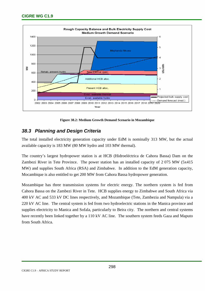
CIGRE WG C1.9
CIGRE C1.9 – AFRICA STUDY REPORT
298
Figure 38.2: Medium Growth Demand Scenario in Mozambique
38.3 Planning and Design Criteria
The total installed electricity generation capacity under EdM is nominally 313 MW, but the actual
available capacity is 183 MW (80 MW hydro and 103 MW thermal).
The country’s largest hydropower station is at HCB (Hidroeléctrica de Cahora Bassa) Dam on the
Zambezi River in Tete Province. The power station has an installed capacity of 2 075 MW (5x415
MW) and supplies South Africa (RSA) and Zimbabwe. In addition to the EdM generation capacity,
Mocambique is also entitled to get 200 MW from Cahora Bassa hydropower generation.
Mozambique has three transmission systems for electric energy. The northern system is fed from
Cahora Bassa on the Zambezi River in Tete. HCB supplies energy to Zimbabwe and South Africa via
400 kV AC and 533 kV DC lines respectively, and Mozambique (Tete, Zambezia and Nampula) via a
220 kV AC line. The central system is fed from two hydroelectric stations in the Manica province and
supplies electricity to Manica and Sofala, particularly to Beira city. The northern and central systems
have recently been linked together by a 110 kV AC line. The southern system feeds Gaza and Maputo
from South Africa.

CIGRE WG C1.9
CIGRE C1.9 – AFRICA STUDY REPORT
299
Figure 38.3: Demand and Energy Supplied in Mozambique
Figure 38.4: National Grid Status in Mozambique

CIGRE WG C1.9
CIGRE C1.9 – AFRICA STUDY REPORT
300
Figure 38.5: Development of National Grid in Mozambique
38.4 Planning Approaches and Methods
The long-term vision of EdM is to establish a major transmission backbone network to connect the
existing three transmission systems of the northern, central and southern areas. The preference is for
an EHV AC transmission system in order to establish step-down substations at various points to supply
regional networks and encourage load growth.
There is significant potential for new hydro and coal generation in the north of the country. A
significant portion will be for export to the Southern African Power Pool or directly to South Africa,
which is the largest consumer in the region. The preference is for an EHV AC transmission network
down the length of the country, but due to the distances involved, HVDC is also under consideration
for portions of the network.
Plans for a gas-fired power plant to supply electricity to South Africa and Mozambique for two years
have been unveiled by UK-based power specialist Aggreko and South African investment company
Shanduka.
"This is thought to be the first project by a private company to supply an interim cross-border power
solution to two utilities in southern Africa, and underlines the potential benefits that can accrue to
countries sharing resources," the two companies said in a statement this week.
The 107-megawatt plant in Ressano Garcia on the border of the two countries was approved by South

CIGRE WG C1.9
CIGRE C1.9 – AFRICA STUDY REPORT
301
African energy regulator Nersa and the Departments of Energy and Public Enterprises.
It will be fuelled by gas from Sasol's Temane gas field and will service Eskom and its Mozambican
counterpart, Electricidade de Moçambique (EDM).
It will be located in Ressano Garcia as it is in close proximity to the existing Sasol gas pipeline, which
runs from northern Mozambique through to South Africa, as well as a 275 kV transmission corridor.
In addition, Aggreko will install containerised power generation units, which will be shipped in from
Dumbarton in Scotland, and build gas interconnections, a substation, and a 1.5 km 275 kV
transmission line to the main network. This infrastructure will remain intact once the installation is
dismantled.
Power purchase agreements have been signed by both utilities and Eskom will utilise 92 megawatts of
the available capacity, while EDM will use 15. The joint venture is expected to bring in revenues of
about US$250-million over its operational period, which should begin in October and carry on until
July 2014.
Eskom is planning to use the power to bolster its base-load capacity ahead of the introduction of new
generation capacity from the Medupi coal-fired power station, which is scheduled to begin operating
towards the end of 2013. EDM has contracted with the facility to meet its daily peak demand.
The project is expected to complement other alternative energy initiatives South Africa is embarking
on, including a 100 MW concentrated solar power plant in Upington in the Northern Cape, as well as a
100 MW wind power project in Sere, outside Cape Town.
Eskom is also currently building two major coal-fired power stations, Medupi and Kusile, in Limpopo
and Mpumalanga respectively. But until the completion of the stations, South Africa's high energy
demands are expected to continue to threaten the country's supply.
It is hoped that with the agreement this week, both South Africa and Mozambique will get much-
needed additional power, with the project also underlining the importance of the two countries as
energy hubs for the entire southern African region.
According to Aggreko's chief executive, Rupert Soames, the contract was not only important for South
Africa and Mozambique but for southern Africa as a whole.
"We also hope this project will be an example for other countries seeking to optimise their resources
and manage the supply of regional power."
The companies envisage employment and training of about 100 locals with the procurement process

CIGRE WG C1.9
CIGRE C1.9 – AFRICA STUDY REPORT
302
tailored to benefit South African companies.
Figure 38.6: 100-MW gas-fuelled power generation plant
Source: BuaNews
38.5 Specific Technical Issues
Industrial production growth rate: 9% (2008 est.)
Electricity – production: 14.62 billion kWh (2006 est.)
Electricity – consumption: 9.555 billion kWh (2006 est.)
Electricity – exports: 12.83 billion kWh (2006 est.)
Electricity – imports: 9.839 billion kWh (2006 est.) [2]
With no present domestic sources of energy besides biomass, hydropower and a little coal,
Mozambique is forced to import its fossil energy, mostly petroleum. All fossil energy is used for
transportation and industrial purposes. Residential energy use consists of fuelwood and other
combustibles. Mozambique’s Cahora Bassa hydroelectric facility is located on the Zambezi. The
power station, with a nominal capacity estimated at 2 075 MW, currently supplies electricity
domestically, as well as to Zimbabwe and South Africa. Cahora Bassa is operated by Hidroelectrica de
Cahora Bassa (HCB), a joint-venture between Portugal (82 per cent) and EDM (18 per cent). The
government of Mozambique has expressed a desire to have the facility transferred to majority
Mozambican ownership. Currently, Mozambique is seeking funds to modernize the Cahora Bassa
facility at an expected cost of $40 million.[1]
38.6 Financing Issues

CIGRE WG C1.9
CIGRE C1.9 – AFRICA STUDY REPORT
303
The major power project donors are:
The Norwegian, Swedish and Danish Government Aid Agencies (NORAD, SIDA and
DANIDA),
The French Agency for Development,
World Bank, and
African Development Bank (ADB).
38.7 Human Resources
The economy of Mozambique continues to be dominated by agriculture. Major exports include
prawns, cotton, cashew nuts, sugar, citrus, copra and coconuts, and timber.
The government is seeking investors for a new 2 400-MW hydroelectric facility on the Zambezi River,
about 43 miles south of the Cahora Bassa dam. Once construction is underway, it could take up to
eight years for generation to begin. South Africa’s Eskom has expressed interest in constructing a 100-
MW power station adjacent to Mozambique’s Moatize coal fields. [2]
Malawi’s Shire river supports four hydroelectric plants, which account for the majority of the
country’s electrical output. A 31-mile power-supply link from Mozambique’s Cahora Bassa dam, is
under construction; however, a lack of resources has prevented the project from moving forward.
Additional work continues on the Kapichira hydroelectric power scheme that is designed to add 128
MW to the country’s capacity. [2]

CIGRE WG C1.9
CIGRE C1.9 – AFRICA STUDY REPORT
304
38.8 References:
1. http://www.energyrecipes.org/reports/genericData/Africa/061129%20RECIPES%20countr
y%20info%20Mozambique.pdf
2. http://en.wikipedia.org/wiki/Economy_of_Mozambique
3. http://www.southafrica.info/business/economy/infrastructure/gas-power-
080612.htm#ixzz24s7OPfIK

CIGRE WG C1.9
CIGRE C1.9 – AFRICA STUDY REPORT
305
39. Namibia
39.1 Electricity Industry Structure
Regulation
The Electricity Control Board (ECB) is the legislative supervisory body for the electricity industry in
Namibia. The ECB primary role is to provide licenses, to approve tariffs and to approve infrastructure
expansion plans. The ECB regulates electricity generation, transmission, distribution, supply, import
and export in the country. The ECB is responsible for enforcing the grid code which serves as a
regulatory guideline for NamPower and the Regional Electricity Distributor’s (RED’s) operations.
The Board is also involved in strategic forward planning and internal support functions
The Ministry of Mines and Energy has overall control over the country’s energy resources. The
Ministry ensures that the supply of electricity is adequate, reliable and affordable for the whole nation.
The Ministry is also responsible for rural electrification and the administration of the Solar
Electrification Revolving Fund [1].
Utilities
NamPower was established in 1964 and it is now a company entirely owned by the government of
Namibia. NamPower operates all the existing power plants in the country and the national power grid
at the transmission level. NamPower is a member of the Southern African Power Pool (SAPP)
organization which comprises all power utilities for countries in the Southern African Development
Community (SADC) region. NamPower buys and sells electricity regionally through its Energy
Trading business unit.
In the past the distribution of electricity was mainly done by NamPower as well as the municipalities
and town councils. In 1998 the formation of the REDs was recommended in order to improve the
quality of service and supply and to boost the economy of the power distribution sector in the country.
A RED is an asset-based company that is in charge of distributing and supplying electricity to
customers within a defined large geographic area. It was envisaged to form five REDs which are
NORED, CENORED, Erongo RED, Central RED and Southern RED. At the moment NORED,
CENORED and Erongo RED have been implemented. NamPower supplies power to all distribution
customers in the central and southern region of the country; these include the municipalities of
Keetmanshoop and Mariental [2].

CIGRE WG C1.9
CIGRE C1.9 – AFRICA STUDY REPORT
306
Figure 39.1: Geographic Location of the REDs
Structures
Generation
In Namibia, electricity is generated and transmitted by NamPower. The power utility also supplies
power to all transmission customers such as the mines and large industries.
The three existing power generating plants in Namibia are:
Ruacana hydro power station
This power station is located in the North on the borders between the Namibia and Angola near
the Ruacana falls. The power station was commissioned in 1978. The water from the Kunene
River is used to generate 240 MW from three turbines. A fourth unit is being installed and it is
expected to generate 90 MW by March 2012.
Van Eck coal power station
Installed in 1972, this power station is situated in the northern industrial area of Windhoek (the
capital city). The power station has four units with a total capacity of 120 MW.
Paratus diesel power station
This diesel power station was commissioned in 1976 in Walvis Bay. It has four units
generating 4.6 MW each. The power station is mainly used as a standby station for the coastal

CIGRE WG C1.9
CIGRE C1.9 – AFRICA STUDY REPORT
307
areas.
The Anixas power station will be constructed adjacent to the Paratus power station in Walvis Bay.
This diesel fuelled power station will have a capacity of 21.5 MW and it will be commissioned at the
end of 2010.
Proposed power generation projects being investigated:
Kudu Gas.
Bynes.
Epupa.
Orange River Hydro Power.
Popa Falls.
Luderitz wind.
Walvis coal .
Transmission.
All the transmission lines are monitored and maintained by NamPower. The AC transmission voltage
levels are 400 kV, 330 kV, 220 kV, 132 kV and 66 kV. The DC Caprivi Link Interconnector will be
commissioned in 2010.
The Caprivi Link Interconnector is a 970 km long 350 kV HVDC bipolar line that has been
constructed recently between Zambezi and Gerus substations. It is aimed to provide an asynchronous
link between the Namibian, Zambian and Zimbabwean grids. This will ensure a reliable power
transfer capability between the east and the west of the SAPP. The project has two phases with the
first phase due for completion in 2010, while phase two will involve installing a 400 kV AC line
between Gerus and Auas substations. [3]
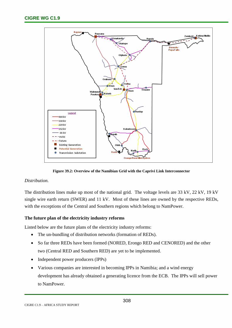
CIGRE WG C1.9
CIGRE C1.9 – AFRICA STUDY REPORT
308
Figure 39.2: Overview of the Namibian Grid with the Caprivi Link Interconnector
Distribution.
The distribution lines make up most of the national grid. The voltage levels are 33 kV, 22 kV, 19 kV
single wire earth return (SWER) and 11 kV. Most of these lines are owned by the respective REDs,
with the exceptions of the Central and Southern regions which belong to NamPower.
The future plan of the electricity industry reforms
Listed below are the future plans of the electricity industry reforms:
The un-bundling of distribution networks (formation of REDs).
So far three REDs have been formed (NORED, Erongo RED and CENORED) and the other
two (Central RED and Southern RED) are yet to be implemented.
Independent power producers (IPPs)
Various companies are interested in becoming IPPs in Namibia; and a wind energy
development has already obtained a generating licence from the ECB. The IPPs will sell power
to NamPower.

CIGRE WG C1.9
CIGRE C1.9 – AFRICA STUDY REPORT
309
Single buyer
At the moment, NamPower operates as a single buyer. The government through the ECB, is
reviewing the single buyer model.
Listed below are the two suggestions under review concerning energy trading:
Energy trading to be an entity on its own
Modified single buyer. This option suggests that various independent power generating
companies would sell power to large customers (i.e. mines; cities and factories) and export to
neighbouring countries.
Grid codes and roles
The Namibian grid code is drawn up by appointed experts, the grid code advisory committee, which
makes recommendations for approval by the Ministry of Mines and Energy. The ECB acts as the
administrative authority for the Grid Code ensuring that the Grid Code is compiled, approved and
implemented for the benefit of the industry. The grid code participants are generating sections,
transmission, distributors, system operators, single buyers and transmission customers. [4]
The grid code has six documents namely:
(i) The Governance code.
This document consists of guidelines on how to update the grid code.
The document has procedures on the version controls, amendments and exemption
processes.
(ii) The Preamble
This document provides the background for the grid code and its various sub-sections.
It contains detailed definitions of terms, acronyms and abbreviations used in the grid
code documents. The document also provides an overall definition for the electricity
industry structure.
(iii) The Network code
This code contains a set of connection conditions for generators, distributors and end-
use customers. The document also stipulates the standards used to plan and develop the
transmission system
i. The Metering code
This code enforces metering standards and requirements that should be adhered to. The

CIGRE WG C1.9
CIGRE C1.9 – AFRICA STUDY REPORT
310
document has guidelines on metering databases, data validation and verification, testing
of metering installations and confidentiality on metering data.
ii. The System Operation code
This code sets out the operational tasks and roles for the participants of the
Interconnected Power System (IPS). The code also provides guidelines for normal
operating procedures, voltage control, commissioning, emergency and contingency
planning and outage planning for the grid.
iii. The Information Exchange code
This code defines the responsibilities of parties with regard to the provision of
information for the implementation of the grid code. The information requirements as
defined for the service-providers, the ECB and customers are necessary to ensure non-
discriminatory access to the transmission system and the safe, reliable provision of
transmission services. The information requirements are divided into planning
information, operational information and post-dispatch information.
39.2 Load and Energy Forecasting
Economic Growth Factors and Load Growth
The Namibian economy is dependent on the following four sectors:
Mining.
Agriculture.
Fishery.
Tourism.
In Namibia, mining contributes almost one third of the total gross domestic product, thus the mining
sector has the biggest influence on power load growth. Prices of minerals such as diamonds, uranium,
gold, silver, zinc, copper, lead and tin have a direct influence on the load growth of the country.
The mining sector has an effect on the electrical network’s infrastructure, especially at the transmission
level.
The Namibian power sector restructuring has no impact on the load and energy demand growth. This
is because the restructuring was just an unbundling of the existing distribution supply industry. The
ownership of the distribution networks which were transferred to the REDs did not result in additional
energy consumption or load increases.

CIGRE WG C1.9
CIGRE C1.9 – AFRICA STUDY REPORT
311
Figure 39.3: Predicted Load Growth [5]
Load forecasting Approach and Methodology
A relational analysis is used to predict the future annual maximum demand for the various load points
as accurately as possible. Historical load data is used as the main input to the model to determine
future trends for every load point in the network. Load data for closed down industries and mines is
removed from the historical load data. New development loads and step loads as specified by
customers are added to the forecasted load to determine future load. This model is a worst-case
scenario such that future peak load that may occur is expected to be lower than the forecasted load for
that specific year. Step loads as specified by customers are added to the forecasted load to determine
future load. Three forecast models were constructed to cater for the varying probabilities (low,
medium and high) of new step loads that may materialize within the next five years. The three load
forecast models are referred to as;
High Probability/Low growth (only high probability step loads are taken into account),
Medium Probability/Medium growth (high and medium probability step loads are taken into
account), and
Low Probability/High growth (all probable step loads are taken into account).
From a system planner’s perspective, the High Probability/Low Growth model is the preferred forecast
model for use in Transmission Master Plan studies [5].
Demand forecasts are used in transmission planning while demand and energy forecasts are used for
integrated resource planning (IRP) and financial planning.

CIGRE WG C1.9
CIGRE C1.9 – AFRICA STUDY REPORT
312
-
200
400
600
800
1 000
1 200
1 400
1 600
1 800
2 000
Demand Forecast Scenarios
Medium Forecast
High Growth
Low Growth
Vision 2030 scenario
Figure 39.4: Forecast Demand Increase in MW for Next 25 Years [6]
The daily load forecast
The daily forecast is compiled on a daily basis by the Energy Trading business unit. This forecast
looks at the network’s aggregated demand in order to predict the following day’s demand. The
forecast results are used by the energy traders to optimize the available supply options in order to meet
the foreseen demand.
The forecast depends on historic data and on the factors listed below:
Weather conditions (Season).
Day type (working day/holiday/weekend).
Major maintenance on the network.
Major step loads coming onto the system on that day.
The load forecast is prepared by using the bottom-up method at feeder and substation level. Diversity
factors are applied to applicable feeders so that all loads on the transmission and distribution networks
are scaled according to their maximum demand of the previous year. Load diversification ensures that
transmission and distribution loads are forecasted on the same level.
NamPower maintains communication with the REDs to keep track of the changing customer load
density. The REDs communicate with the supply business section of NamPower regarding their latest
customer additions.
The Namibian grid has no dispersed generation.

CIGRE WG C1.9
CIGRE C1.9 – AFRICA STUDY REPORT
313
39.3 Planning and Design Criteria
Generation Planning
Generation planning is performed through Integrated Resource Planning (IRP) which is headed by
energy trading.
All considered generation options are compiled into an Integrated Resource Plan (IRP) with their time
lines. The IRP is a model used to study different generation scenarios to determine financial
implications that may arise. The IRP takes cognizance of medium-long-term power purchase
agreements. The IRP considers future demands, and the viability and affordability of each generation
option. A financial analysis is carried out on IRP options to determine which future generation option
is cheaper.
Levels of generation reserve are based on the Southern African Power Pool (SAPP) guidelines.
Namibia’s generation reserve margin is determined by the South African generation.
The generation mix in Namibia consists of three forms of generation. The Paratus power station serves
as stand-by generation which is used in cases of high demand or emergencies. The Van Eck power
station is operated because the country’s demand has grown beyond the Ruacana hydro power station’s
capacity.
Transmission Planning
Transmission planning is carried out in accordance with guidelines in the national grid code. The
guidelines are legislative having been approved by the Ministry of Mines and Energy.
The planning process has various key activities which are:
Identifying the need.
Creating different options that can meet the identified need.
Investigating and studying each option to determine its feasibility and reliability both technical
and financial.
Determining the life-cycle cost for each option using the latest cost rates and discount rates.
Selecting the preferred option based on a least cost approach.
Compiling a financial proposal for the preferred option.
Requesting approval and initiating execution .
The grid code specifies limits and targets for proposed planning options. These limits and targets
include technical and legal restrictions and they are put in place to ensure system stability, security and
safety of equipment and people.
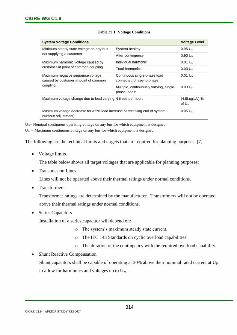
CIGRE WG C1.9
CIGRE C1.9 – AFRICA STUDY REPORT
314
Table 39.1: Voltage Conditions
System Voltage Conditions Voltage Level
Minimum steady state voltage on any bus
not supplying a customer
System healthy 0.95 UN
After contingency 0.90 UN
Maximum harmonic voltage caused by
customer at point of common coupling
Individual harmonic 0.01 UN
Total harmonics 0.03 UN
Maximum negative sequence voltage
caused by customer at point of common
coupling
Continuous single-phase load
connected phase-to-phase:
0.01 UN
Multiple, continuously varying, single-
phase loads:
0.03 UN
Maximum voltage change due to load varying N times per hour:
(4.5Log10N) %
of UN
Maximum voltage decrease for a 5% load increase at receiving end of system
(without adjustment):
0.05 UN
UN= Nominal continuous operating voltage on any bus for which equipment is designed
UM = Maximum continuous voltage on any bus for which equipment is designed
The following are the technical limits and targets that are required for planning purposes: [7]
Voltage limits.
The table below shows all target voltages that are applicable for planning purposes:
Transmission Lines.
Lines will not be operated above their thermal ratings under normal conditions.
Transformers.
Transformer ratings are determined by the manufacturer. Transformers will not be operated
above their thermal ratings under normal conditions.
Series Capacitors
Installation of a series capacitor will depend on:
o The system’s maximum steady state current.
o The IEC 143 Standards on cyclic overload capabilities.
o The duration of the contingency with the required overload capability.
Shunt Reactive Compensation
Shunt capacitors shall be capable of operating at 30% above their nominal rated current at UN
to allow for harmonics and voltages up to UM.
CIGRE WG C1.9
CIGRE C1.9 – AFRICA STUDY REPORT
315
Circuit Breakers
The following breaker limits shall not be exceeded:
o Single-phase breaking current: 1.15 times three-phase fault current
o Peak making current: 2.55 times three-phase rms. fault
current
o Secondary ARC current during single phase reclosing
In any part of the network, the secondary ARC current shall not exceed the following limits:
o 20 amps rms. with recovery voltage of 0.4 p.u.
o 40 amps rms. with recovery voltage of 0.25 p.u.
The power quality standards of the Namibian grid are based on the NRS048-1, 2, 3, 4, 5 Standards.
Currently, NamPower only monitors the power quality of the grid. Impedographs are used at all
substations with voltage levels of 33 kV and below (interface between NamPower transmission and its
local customers) and at tie lines (these are points connecting to neighbouring countries on the
transmission levels) to continuously monitor the power quality. NamPower actively manages the
power quality levels of the national grid on a daily basis.
39.4 Planning Approaches and Methods
NamPower utilizes the deterministic planning approach by using a least-cost planning methodology.
Coordination Planning
In the SADC region co-ordination planning between power utilities is performed through the SAPP.
Roles of Interconnections
The generation capacity of Namibia is lower than the country’s power demands. Hence NamPower
imports power from neighbouring countries to meet the country’s demand. The wheeling of power is
only possible through interconnections which are the key to ensuring sufficient power supply to the
country. At the moment, NamPower wheels power from Eskom and ZESA (Zimbabwe).
Environmental Issues
NamPower’s Safety Health and Environment (SHE) section has put in place an environmental policy
to protect the environment and prevent pollution in areas where NamPower operations are carried out.
The aim of the policy is to provide NamPower employees with guidance on how to carry out work
activities without harming the surrounding environment. The policy corresponds with the country’s
legislative laws on the environment and it is applied to each and every project from the planning phase
through to commissioning.
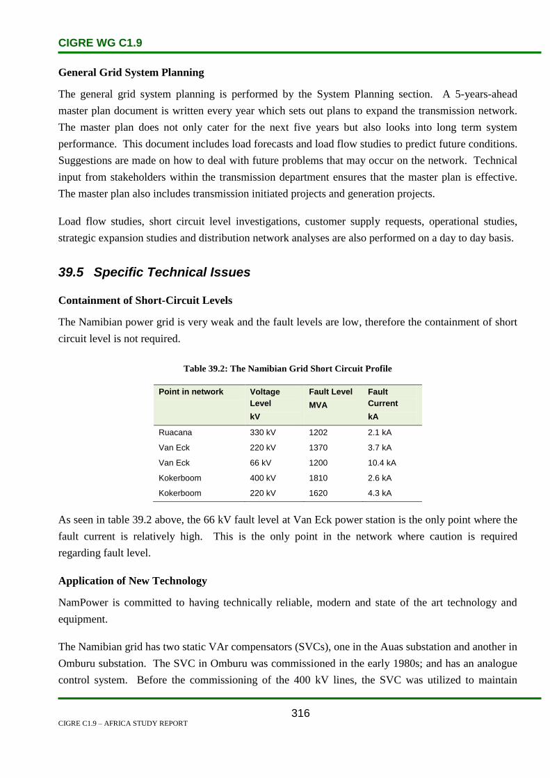
CIGRE WG C1.9
CIGRE C1.9 – AFRICA STUDY REPORT
316
General Grid System Planning
The general grid system planning is performed by the System Planning section. A 5-years-ahead
master plan document is written every year which sets out plans to expand the transmission network.
The master plan does not only cater for the next five years but also looks into long term system
performance. This document includes load forecasts and load flow studies to predict future conditions.
Suggestions are made on how to deal with future problems that may occur on the network. Technical
input from stakeholders within the transmission department ensures that the master plan is effective.
The master plan also includes transmission initiated projects and generation projects.
Load flow studies, short circuit level investigations, customer supply requests, operational studies,
strategic expansion studies and distribution network analyses are also performed on a day to day basis.
39.5 Specific Technical Issues
Containment of Short-Circuit Levels
The Namibian power grid is very weak and the fault levels are low, therefore the containment of short
circuit level is not required.
Table 39.2: The Namibian Grid Short Circuit Profile
Point in network Voltage
Level
kV
Fault Level
MVA
Fault
Current
kA
Ruacana 330 kV 1202 2.1 kA
Van Eck 220 kV 1370 3.7 kA
Van Eck 66 kV 1200 10.4 kA
Kokerboom 400 kV 1810 2.6 kA
Kokerboom 220 kV 1620 4.3 kA
As seen in table 39.2 above, the 66 kV fault level at Van Eck power station is the only point where the
fault current is relatively high. This is the only point in the network where caution is required
regarding fault level.
Application of New Technology
NamPower is committed to having technically reliable, modern and state of the art technology and
equipment.
The Namibian grid has two static VAr compensators (SVCs), one in the Auas substation and another in
Omburu substation. The SVC in Omburu was commissioned in the early 1980s; and has an analogue
control system. Before the commissioning of the 400 kV lines, the SVC was utilized to maintain

CIGRE WG C1.9
CIGRE C1.9 – AFRICA STUDY REPORT
317
voltage stability due to high line impedances northward of Omburu. The SVC also has a switching
logic scheme for over-frequency, over-voltage and under-voltage conditions. The Auas SVC was
commissioned in 2001; and has a special resonance detection algorithm. This algorithm ensures that
the network’s resonance frequency is maintained between 68–70 Hz when closing a 400 kV line. The
synchronous condensers at the Van Eck power station are also used to keep the resonant frequency
slightly above 50 Hz when the Auas SVC is out of service.
The Auas SVC has three external reactors connected to it, which are controlled by the substation’s
Remote Terminal Unit (RTU). This SCV has two filter banks which are double tuned for the 5th
and
7th
harmonics.
SVCs are expensive because of the sophisticated technology and high maintenance costs. Nonetheless,
SVCs are essential to the network to ensure voltage and transient stability.
High Voltage Direct Current (HVDC) is a new technology introduced into the Namibian grid on the
new Caprivi interconnector link currently under construction. The HVDC technology incorporates
Insulated Gate Bipolar Transistor (IGBT) technology. The IGBT technology is capable of controlling
active and reactive power flows, hence it can perform voltage regulation.
The HVDC also has an Optimized Pulse Width Modulator (OPWM). The OPWM eliminates most of
the harmonics in the system and damps the remaining harmonics to certain levels. The remaining
harmonics are removed from the system by filters. Optimized pulse width modulation is based on the
principle of mathematically calculating a modulation index for the pulse width modulator. The IEC
61850 communications standard will be used on the HVDC, and it will use GOOSE to transmit and
process all data for the system.
Planning Against System Collapse
The estimated cost of a system collapse is approximately 12 times the selling cost of each unit. In
Namibia a blackout is estimated to last between 45 minutes and 1 hour. The country has no heavy
industries that would experience severe damages in the case of a blackout. Static VAr compensators
are used to dynamically prevent voltage collapse. The SVCs are placed on the backbone of the
transmission grid for effectiveness. These devices work in conjunction with reactors and capacitors to
ensure the stability of the system. The DIgSILENT power factory software package is used to perform
dynamic studies for the network for various scenarios. These studies are performed to determine
conditions that could initiate system collapse.
Network Configurations
Namibia is a country with a size of 824 268 km² and a population of 2.1 million. This low population
in a big country results in a grid that has infrastructure concentrated in a few areas in the country. This

CIGRE WG C1.9
CIGRE C1.9 – AFRICA STUDY REPORT
318
has resulted in a grid that has long high voltage lines (radial) which are loosely meshed. The Namibian
network has a strong source in the south (Eskom) and a hydro generating source in the north of the
country.
The two sources are connected together by 400/330/220 kV backbone lines. When Ruacana
generation is low (hydro), the loss of a 400 kV line between Kokerboom and Auas can cause failure to
supply all the load, thus resulting in load shedding
Embedded/Dispersed Generation
The Namibian grid has no embedded generation.
Voltage Stability and Reactive Compensation
The Namibian network is a weak network, thus SVCs are placed in the network to cater for voltage
stability. There are two SVCs in the Namibian network, one at the Omburu substation and another one
at Auas substation.
The switching of reactors and capacitors is planned in such a way that the network is operated within
the network specifications.
Line and bus bar reactors are utilized to maintain voltage stability of the network within the required
limits.
39.6 Financing Issues
Three types of funding used by NamPower:
Cash from operations.
Equity.
Debt.
A combination of the above mentioned methods is used to finance new projects and to maintain
operations of NamPower. Cash from operations refers to profit made from the operations of
NamPower. Equity is the capital given to NamPower by the government of Namibia. The government
would specify how much of this money would be used for a specific project. In the past three years,
the company has received N$ 1 billion from the government to supplement its finances.
Two approaches are used to borrow money:
Development banks.
Bond insurance.

CIGRE WG C1.9
CIGRE C1.9 – AFRICA STUDY REPORT
319
The company’s financial performance determines its ability to pay back its loans and to keep
operating. In the case where the company is unable to pay back the money borrowed, the company
would formulate a re-financing process together with the lender. If the re-financing process fails, then
the government is expected to step in and assist because it is the sole share holder.
The tariffs are low, thus not cost effective. This is a challenge that hinders private investors from
investing in the electricity sector. Independent Power Producers (IPPs) have not been introduced yet
because the tariffs are too low for them to make profits.
So far the company prefers bond funding and funding from development banks. Tight funding is not
preferred because it restricts the company in terms of preference of equipment and technology choices.
NamPower has a bond insurance of N$ 3 billion, of which only N$ 750 million has been used for the
Caprivi link and the Ruacana fourth unit.
Money borrowed from development banks is mostly used for infrastructure projects. Since NamPower
is highly credit rated and guaranteed by the government; the lending agencies give long dated period
loans (15–20 years). A grace period of 2–3 years can also be given to prolong the payback period.
39.7 Human Resource Issues
Each business unit is responsible for the training of its employees and the funds required for the
training. The funds for employee training are part of each business unit’s yearly budget. The Human
Resources section is the custodian when it comes to employee training.
39.8 References
1. http://www.mme.gov.na/directe.htm
2. The Planned Regional Electricity Distributors (REDs) for Namibia, October 2005 by ECN
3. High Level Overview on the Caprivi Link Interconnector, 01 July 2009
4. The Namibian Grid Code – Governance Code, November 2009 by ECN
5. Transmission Maximum Demand Load Forecast; March 2009 by F Binneman
6. NamPower 2009 Base Case Demand Forecast; 4 August 2009
7. The Namibia Grid Code – The Network Code; May 2005 by ECN

CIGRE WG C1.9
CIGRE C1.9 – AFRICA STUDY REPORT
320
40. Niger
40.1 Electricity Industry Structure
Utilities
The Electricity industry consists of two major companies:
The Electricity utility Société Nigerienne d’Electricité (NIGELEC) and
the Société Nigérienne du Charbon d’Anou Araren (Sonichar) that runs the coal-fired power
station located in the northern part of NIGER at Anou-Araren.
NIGELEC has the duty to give power to people throughout the country, whereas Sonichar is only a
producer.
Nigelec was created on 7 September 1968. Its mission is to produce, transmit and distribute electrical
power throughout the country.
Sonichar was created on 23 January 1975. Its mission is to supply power to the mining companies in
order to improve the balance of payments of the country. In addition to supplying the mining
companies, the power produced is supplied to the cities of Akokan Tchirozerine and Agadez. Sonichar
has two generating sets of 18.8 MW each.
The 132 kV line between Sonichar and Akokan supplies power to the two mining companies i.e.
Cominak and Somair, and the cities of Arlit, Tchirozérine and Agadez. This line is rented to
NIGELEC by Sonichar on a yearly based contract.
Regulations
The Autorite Multisectorielle de Regulation was created on 26 October 1999.
It has four sectors namely, Energy, Water, Transport and Telecommunications.
Its mission is to regulate the sectoral activities.
The Energy sector is in charge of regulating the Power sector, among other things.
Structure of Generation
Generation is comprised mainly of diesel generator sets. There are two STAL Laval GT35 gas
turbines of 10 MW each in Niamey II Power Station. Goudel Power Station has an Alsthom PC4V12
diesel set of 10 MW capacity. Goudel and Niamey II power stations supply power to Niamey, the
capital city of Niger.

CIGRE WG C1.9
CIGRE C1.9 – AFRICA STUDY REPORT
321
A 132 kV line from Birnin-Kebbi (Nigeria) to Niamey (Niger) supplies power to Niamey. In the case
of a power failure on the Nigerian grid system, supplies are taken from the Goudel and Niamey II
power stations which are available as spinning reserve.
The main power stations are:
Niamey II: 20 MW
Goudel: 10 MW
The peak load recorded in the Niamey area is 70 MW in the year 2008.
Throughout the country there are small scattered diesel generator sets from 60 kVA to 1 360 kVA
The total installed generating capacity in Niger is 96 MW.
The government is constructing a hydro facility at Kandadji. The Islamic Development Bank has taken
the lead in financing the project. It was first conceived in the mid 1970s but construction only began in
2008. The power plant is located on the Niger River about 120 miles upstream of Niamey. The 165-
MW facility is estimated to cost $709 million and is expected to become operational in 2013.
The state run electric utility Société Nigerienne d’Electricité (NIGELEC) imports 87% of its electrical
needs from the National Electric Power Authority in Nigeria via a 132 kV electrical connection that
was constructed in 1976 and covers 260 km. It also receives hydroelectric power from Nigeria. There
are two thermal power plants, one of which uses coal and the other uses oil [8].
Structure of Transmission, Distribution and Retail Business
High voltage transmission lines: 132 kV and 66 kV.
The main interconnection lines are as follows:
Table 40.1: Capacity of Interconnecting Lines – Niger
132 kV
Birnin-Kebbi Line
132 kV
Katsina-Niger
Centre-East Line
Nominal Power 80 MW 30 MW
Real power 80 MW 30 MW
The total 132 kV line length is 709 km.
The total 66 kV line length is 434 km.
Medium Voltage (MV) distribution lines: 33 kV and 20 kV.

CIGRE WG C1.9
CIGRE C1.9 – AFRICA STUDY REPORT
322
Total MV distribution line length is 1 912.7 km.
Low Voltage (LV) distribution lines: 380 V, and 220 V
Total LV distribution line length is 1 436.1 km
The total distribution network length is 3 348.8 km
40.2 Load and Energy Forecasting
Electricity consumption: 443.2 million kWh (2006 est.)
Table 40.2: Electricity Consumption – Niger
Year Electricity Consumption
kWh
Rank
Change
%
Date of
Information
2003 325 100 000 165 2001
2004 325 100 000 165 0.00 % 2001
2005 327 600 000 167 +0.77 % 2002
2006 263 900 000 166 -19.44 % 2003
2007 415 800 000 159 +57.56 % 2004
2008 443 200 000 161 +6.59 % 2006 est.
Definition: This entry consists of total electricity generated annually plus imports and minus exports,
expressed in kilowatt-hours. The discrepancy between the amount of electricity generated and/or
imported and the amount consumed and/or exported is accounted for as loss in transmission and
distribution.
Source: CIA World Factbook – unless otherwise noted, information is accurate as of 18 December
2008
40.3 Planning and Design Criteria
The contribution of electricity throughout the country entails small scattered diesel generators. The
NIGELC Company is responsible for most of the power generation in Niger. NIGELEC operates the
generators with a combined capacity of 96 MW. Generation is comprised mainly of diesel generator
sets. There are two STAL Laval GT35 gas turbines of 10 MW each in Niamey II Power Station.
Goudel Power Station has an Alsthom PC4V12 diesel set of 10 MW capacity. Goudel and Niamey II
power stations supply power to Niamey, the capital city of Niger.The 132 kV backbone is planned to
meet N-1 contingencies [1].

CIGRE WG C1.9
CIGRE C1.9 – AFRICA STUDY REPORT
323
40.4 Planning Approaches and Methods
The Kandadji dam will be the biggest multipurpose dam in the Niger River. The dam will generate
hydropower and is aimed at controlling the flow of the Niger River, holding water during the dry
season to maintain a minimum flow and making downstream irrigation possible [1].
The project is a very high profile project for Niger. According to the Prime Minister at the time of
initiating construction, Seyni Oumarou, ‘no other development project will have sparked so much long
term interest or such high expectations’. The first brick of the dam was laid by the President of Niger,
Mamadou Tandjaa [2].
40.5 Specific Technical Issues
The earth dyke dam will be 8.4 km dam long, creating a reservoir of 1.6 billion m3 and a regulated
discharge of 120 m3/second (3.8 km3/year) in Niamey. The hydroelectric plant will have a capacity of
130 Megawatt, and a 132 Kilovolt high voltage line will be built over 188 km to Niamey. Irrigation
development will consist of a first phase of 6 000 hectares mainly for the benefit of resettled
communities, with a medium-term target in 2034 of 45 000 hectares out of an irrigable potential of
122 000 hectares [3].
40.6 Financing Issues
The financial costs of the broader project, including the infrastructure for irrigation and drinking water
supply, are estimated at US$670 million. Funding of $236 million USD was pledged by the Islamic
Development Bank. In February 2009, an additional US$15 million was pledged by the OPEC Fund
for International Development [4] The African Development Bank approved a combined loan and
grant of US$62 million in October 2008 [5]. In January 2010 the Saudi Development Fund approved a
grant of US$ 20 million for the project [6]. Financing for the hydropower station itself is due to come
from a public-private partnership [7].
40.7 Human Resources
The International Monetary Fund (IMF) programme for Highly Indebted Poor Countries deals with
Poverty Reduction and Growth Facility (PRGF).In its effort comply with the IMF’s Poverty Reduction
and Growth Facility plan, the government also is taking actions to reduce corruption and, as the result
of a participatory process encompassing civil society, has devised a Poverty Reduction Strategy Plan
that focuses on improving health, primary education, rural infrastructure, and judicial restructuring. To
conclude this country is improving as a whole nation [6].

CIGRE WG C1.9
CIGRE C1.9 – AFRICA STUDY REPORT
324
40.8 References
1. Niger / AfD Bank Group President receives Niger’s Finance and Economy Minister.
African Press Organization (APO).
2. ReutersAlertNet: Niger begins building dam for food, electricity
3. Republic of Niger, Prime Minister’s Office, High Commission for Niger Valley / African
Development Bank: ‘Kandadji Ecosystems Regeneration and Niger Valley Development
Programme (Kernvdp), Detailed Population Resettlement Plan’. Executive Summary, pg 3–
4
4. OFID: Commitments in 2008
5. African Development Bank:Niger: US$62 Million ADF Funding for the development of
Niger Valley Ecosystems
6. African Manager: Saudi Fund grants US$20 million to Niger for Kandadji dam
7. ReutersAlertNet: Niger begins building dam for food, electricity
8. http://www.estandardsforum.

CIGRE WG C1.9
CIGRE C1.9 – AFRICA STUDY REPORT
325
41. Nigeria
41.1 Electricity Industry Structure
Nigeria’s electricity sector is served by the National Electricity Power Authority (NEPA), which is the
monopoly supplier of generation, transmission and distribution services to three million customers.
The Federal Ministry of Power and Steel sets electricity policy and approves investments in the sector.
Electric power generation in Nigeria dates back to 1896 and the first electricity company Nigeria
Electricity Supply Company (NESCO) was established in 1929. Then, the Electricity Corporation of
Nigeria (ECN) was created in 1951 followed by Niger Dams Authority (NDA) in 1962. Both bodies
merged in 1972 to become National Electric Power Authority (NEPA).
Subsequently, in the 1990s, new texts were adopted as follows:
The Electricity Act. Cap 106 LFN 1990 which set the models for electric power generation,
transmission and distribution, and
The National Electricity Power Authority Act. Cap 256 LFN 1990, which created the new
NEPA and defined its mode of operation.
Until 1998, NEPA, which was a state utility and the very first operator, had a monopoly on electric
power generation, transmission, distribution and sales in Nigeria. Then the act that created NEPA was
amended to allow other stakeholders to operate in the sector, especially in the power generation field.
As of 2001, under the National Commission for Privatization, the Federal Government decided to
embark on reforms in the electricity sector with the primary aim of establishing an ‘electricity supply
industry’ (ESI).
The priority of these reforms was to create a viable electric power market with a clearly defined legal
and institutional framework, promoting competition in electricity generation and sales, which would
also attract national and foreign private investors.
These reforms led to the adoption of the Electric Power Sector Reform Act 2005, in March 2005,
which repealed the previous texts. This act defined a restructuring plan for NEPA to include several
companies. It opened the sector to competition and created a regulatory commission for the electric
power sector, the Nigerian Electricity Regulatory Commission (NERC) and the Rural Electrification
Agency (REA).
In 2005, NEPA was replaced by the Power Holding Company of Nigeria (PHCN), which will serve as
a platform for the actual restructuring during the transition period. It is expected to give way to

CIGRE WG C1.9
CIGRE C1.9 – AFRICA STUDY REPORT
326
eighteen new electricity companies. The companies that will serve in the Nigeria power sector are:
NEPA daughter companies. NEPA will be functionally unbundled into autonomous daughter
companies for generation (GenCos), distribution (DisCos) and transmission (TransysCo).
NEPA itself will be restructured as a holding company for a limited transition period, and later
dissolved.
o DisCos. Up to eleven DisCos will be instituted initially as semi-autonomous business
units subject to monitoring and oversight by NEPA headquarters and later spun off as
independent companies.
o TransysCo. TransysCo will handle transmission construction, maintenance, operations
and dispatch.
Independent Power Producers. New generation in Nigeria will be supplied by independent
power producers (IPPs), not the outgoing NEPA. In the current transition phase, NEPA and the
Ministry execute the power purchase agreements, however in due course all generation
purchases will be re-assigned to the DisCos.
Market Oversight Committee. A Market Oversight Committee will set the market rules and
ensure the efficient administration of energy trading.
Market Operator. The Market Operator will implement the market rules and manage financial
settlements.
Nigerian Electricity Regulatory Commission (NERC). The NERC will regulate all of the new
companies.
The regulation of the sector and monitoring of the sector-based laws of energy, are governed by the
Energy Commission of Nigeria Act, Cap 109 LFN 1990, which granted these prerogatives to the
Energy Commission.
The Nigeria electricity network map is shown in Figure 41.1 below:

CIGRE WG C1.9
CIGRE C1.9 – AFRICA STUDY REPORT
327
Figure 41.1: Nigeria Electricity Network
41.2 Load and Energy Forecasting
In 2002, the peak power supplied by the NEPA network reached 3 500 MW and the total energy
generated for the year was 19 600 GWh. These figures represent the demand that was met by available
generation and transmission facilities, however it is estimated that there is 5 000 MW of unsupplied
demand, most of it already connect to the network. Energy is rationed to the local district distributors,
which in turn switch the feeders to distribute whatever power is available. Many consumers have their
own backup generators in case of power supply failure or load shedding.
It is estimated that the economic gas reserves in Nigeria are sufficient to generate up to 40 000 MW.
Accordingly, the generation expansion plan shown for Nigeria is entirely gas-fired simple cycle and
combined cycle combustion. Under the new liberalized industry structure in Nigeria, all new
generation will probably be provided by IPPs. The market for IPP generation is expected to grow from
700 MW in 2005 to over 6000 MW by 2015.
It remains to be seen whether enough IPPs will step forward to make the required investments. The
estimated price of IPP generation is 3–4 US¢ per kWh, assuming natural gas is supplied by the
government at a very low price. Yet, owing to low billing and collection rates, NEPA’s average
collection of revenue per kWh of energy sent out from the generating plants has been only 2 US¢ per

CIGRE WG C1.9
CIGRE C1.9 – AFRICA STUDY REPORT
328
kWh, i.e. below the cost of generation. However, a recent drive by Government and NEPA
management has raised revenue collection from 40–50% to 70–80%. If sustained or improved, this
will help the affordability of IPPs.
The electricity demand forecast of peak capacity (MW) and energy (GWh) for Nigeria are shown in
Figure 41.2 below. This study forecasts an average growth rate of 7% for peak capacity and 7.2% for
energy.
0
10,000
20,000
30,000
40,000
50,000
60,000
70,000
2004 2006 2008 2010 2012 2014 2016
Year
Co
nsu
mp
tio
n
GWh
MW
Figure 41.2: Nigeria Forecasted Consumption and Annual Maximum Demand
This section presents an indicative generation expansion plan for Nigeria and Niger combined to meet
the demand forecast. The results come from Elfin, a commercial multi-area production simulation
model with a state-of-the art hydro algorithm. The model is used to evaluate the least-cost schedule of
generation additions.
Table 41.1 below shows the existing NEPA generation. NEPA has over 6 000 MW of installed
capacity but the plants have not been properly maintained. The company is restoring around 4 200
MW of generating capacity of which 40% is hydro and 60% is thermal, mainly gas-fired. Most of the
remaining inoperable facilities are beyond economic repair.

CIGRE WG C1.9
CIGRE C1.9 – AFRICA STUDY REPORT
329
Table 41.1: Nigeria Installed Generation Capacity
Station Year Installed Capacity – MW Max Available Capacity in
2002 – MW
Kainji(Hydro) 1967/78 760 480
Jebba(Hydro) 1986/90 540 482
Shiroo(Hydro) 1989/90 600 600
Egbin(Steam) 1985/87 1 320 1 274
Sapele(Steam) 1978 720 150
SapCT 1981 320 50
Delta(SCGT) 1966/90 900 400
Afam(SCGT) 1959/1982 977 248
Ijora(SCGT) 1978 60 15
Totals 6 177 3 700
In addition to the above resources there are two emergency power projects, one in Lagos and one in
Abuja, that operate on a year-to-year basis. In 2005, the electric power generation sources of PHCN
on the interconnected network of Nigeria had a total installed capacity of 6 688 MW shared between
the following:
PHCN’s actual generation fleet of 5 913 MW and,
Private producers; 270 MW for AES, 450 MW for AGIP and 55 MW for STS Ajaokuta.
PHCN power generation installations account for 88.4% of the total installed capacity, while private
producers account for 11.6%.
The power generation fleet is composed of thermal power plants for 71% of the installed capacity, of
which 16.3% is private producers. Hydro-power generation installations account for 29% of the
installed capacity and belong to PHCN which operates and maintains them.
It is estimated that about US$350 million is required per year to expand, replace and maintain the
transmission network. There is no obvious source of funding for expenditure of this magnitude given
NEPA’s current financial outlook.
From the West Africa Power Pool (WAPP) perspective, it is critical that Nigeria addresses its
transmission reliability problems and inadequate control systems, as a prerequisite to integrate its
operations with other WAPP member utilities. In particular, Nigeria must find a way to stabilize its
system frequency.

CIGRE WG C1.9
CIGRE C1.9 – AFRICA STUDY REPORT
330
41.3 Planning and Design Criteria
Power generation in Nigeria over the past 40 years has varied between gas-fired, oil-fired,
hydroelectric power stations to coal-fired stations with hydroelectric power systems and gas-fired
systems taking precedence. This is predicated by the fact that the primary fuel sources (coal, oil, water,
gas) for these power stations are readily available. At present, the installed and available electrical
capacity in the Nigerian generating stations is shown in Table 41.1. Table 41.1 shows that despite a
total grid capacity of 5924.7 MW, only 4586 MW were available. Thus 22% of the installed capacity
was unavailable [4].
The country Nigeria has implemented a new structure called Power sector due to the inadequate
electricity supply. The reform bill, approved by the federal executive council (FEC) is intended to
achieve five objectives [4]:
Unbundle NEPA
Privatize the unbundled entities
Establish a regulatory agency
Establish a rural electrification agency and fund
Establish a power consumer assistance fund.
41.4 Planning Approaches and Methods
Presently, the public stakeholders managing the electric power sector in Nigeria are answerable
simultaneously to the Federal Government and the State Government. The responsibilities of the
government organizations are:
The Federal Government, which determines the major development policies for the sector,
monitors the application and harmonization of energy policies in general, secures foreign
investment and loans, and takes all necessary actions to strengthen energy policies at the
Federal level.
The Federal Ministry in charge of energy. Its duty is to formulate the general policies of the
sector, monitor and assess the implementation of the policies of access to electricity and the
application of the technical standards of the industry. It represents the government in other
federal, regional and international institutions.
Local Governments (of the states), are in charge of developing networks outside the national
interconnected system and building electric power stations according to the provisions of the
1999 Constitution. Their role is also to set the operating rules for the non-interconnected
systems within their territories.

CIGRE WG C1.9
CIGRE C1.9 – AFRICA STUDY REPORT
331
Nigerian Electricity Regulation Commission (NERC) is a Federal agency mandated to create,
promote and protect a viable electric power industry and market. It protects the interests of
consumers, the quality and reliability of electricity, promotes private sector investments and
monitors the operation of the sector. NERC is equally responsible for fixing electricity tariffs
and granting operating licenses. It is also responsible for managing official assistance funds for
electric power consumers, and funds budgeted for access of the deprived populations to
electricity.
Rural Electrification Agency (REA) created by the Electric Power Sector Reform Act 2005, is
responsible for promoting and designing rural electrification plans, with the participation of the
private and public sectors. It is composed of seven members, six of whom are from the six
geopolitical regions. It is the manager of the rural electrification fund.
The National Control Centre in Oshogbo is responsible for dispatching and rationing power to the
distribution districts and directing regional transmission operations. In the past, Oshogbo only had
telephone communication and frequency metering to monitor and operate the network. As a
consequence it was difficult to operate effectively.
There have been some important recent developments. There is a new modern supervisory control and
data acquisition (SCADA) system and a new supplementary Nation Control Center at Shiroro has been
established. The operators at Oshogbo now have consoles to monitor and control the interconnected
generation and transmission systems.
When there is insufficient generation to serve the connected load, NEPA implements a well-
established system to ration the available generation according to a formula that provides set-asides for
priority loads. The remaining energy is then allocated pro rata to the rest of the district loads. Daily
energy rations are communicated by fax to the operators in the districts, where feeder load shedding is
done manually.
41.5 Specific Technical Issues
The number of scheduled and unplanned disconnections on the 330 kV network in 2005 was 529
compared with 839 cases in 2004, which is a significant reduction of 58.6%. On the other hand, it rose
on the 132 kV network from 2 735 incidents in 2004 to 3 585 in 2005, which is a 31.07% increase.
In 2005, the high voltage network of PHCN interconnected system received 23 410 GWh from the
generation centres and supplied 21 401 GWh to the distribution network (MV and LV), which is
91.42% of the energy received. This performance rose by 1.39% compared with 90.06% in 2004.

CIGRE WG C1.9
CIGRE C1.9 – AFRICA STUDY REPORT
332
NEPA’s transmission system is old and the system deteriorated throughout the 1990s without
rehabilitation or investment. However, in the past three years NEPA has made good use of a grant
from the Nigerian Government and a loan from the World Bank for the enhancement of the
transmission network and system operation. However, bottlenecks and reliability problems still plague
the network. The transmission system is under extreme stress when generation exceeds 3 200 MW,
and transmission related outages sometimes cause widespread blackouts.
Due to a shortage of generating capacity resulting from high rate of unavailability of plants, PHCN set
up a load shedding programme which is operated manually. The frequent shut down of generation and
tran Hz. This fluctuation
can constitute a serious handicap to the future operation of the interconnected system at the regional
level. Effective solutions should be sought so as to resolve this problem before the final arrival of
WAPP’s 330 kV coastal backbone.
41.6 Financing Issues
The electricity and gas improvement project in Nigeria will help strengthen the electricity transmission
system and improve service delivery by improving efficiency and gradually reducing losses and
subsidies. The funding will provide support for the ongoing reform programme through technical
assistance and knowledge transfer. Funding was provided by the World Bank.
Other sources of funds for Nigeria electricity projects include the following:
The Government of Nigeria,
Private investors,
African Development Bank, and
European Investment Bank.
41.7 Human Resource Issues
Project management skills are lacking in Nigeria. This is the only way that the numerous instances of
abandoned or failed projects in Nigeria can be explained. Power stations have been built without a gas
supply to fuel them, and without any grid connections to transmit the power to where it is needed.
41.8 References
1. http://www.indexmundi.com/nigeria/electricity_consumption.html
2. http://naijatechguide.blogspot.com/2009/04/project-management-nigeria-training.html
3. http://www.akamaiuniversity.us/PJST8_1_68.pdf
4. 18-3jesa-okoro.pdf

CIGRE WG C1.9
CIGRE C1.9 – AFRICA STUDY REPORT
333
42. Rwanda
42.1 Electricity Industry Structure
Rwanda is small country in the centre of Africa (Great Lakes area), and borders with Tanzania,
Burundi, Uganda and the Democratic Republic of Congo, with about 9 million inhabitants. The total
land area is about 24 950 km2.
Rwanda experienced a civil war and genocide in 1994, that killed more than 1 000 000 and forced
more than 1 000 000 to become a refugees. The urban population represents 17% of the total.
Rwanda’s electricity supply industry is under a national company known as Electrogaz. The utility is
vertically integrated and responsible for the country’s electricity and water.
Currently Electrogaz is in the process of being restructured so as to increase private sector
involvement. Under the new regime, generation is to be opened up to competition, but Electrogaz is to
remain the single buyer.
Independent generation for grid sales:
o The first PPA has been signed.
Independent small grids:
o Contracts are under preparation for a Dutch-supported programme.
Rwanda Utilities Regulatory Agency (RURA):
o This is functional.
The revision of electricity and gas legislation and regulations is under way.
Environmental impact assessments are required.
The electric power supplied to Rwanda comes from the national power stations as well as importation.
The national production is ensured by hydroelectric power stations and the thermal power station.
Electric power is also imported from Rusizi I (DRC), Rusizi II (SINELAC) and UDCL (Uganda).
Rwanda is implementing 26 micro hydro projects and various solar photovoltaic systems for public
institutions, studies for wind energy and market development for solar home systems.
42.2 Load and Energy Forecasting
The econometric method is used to predict the energy demand for Rwanda in the target forecast period
in terms of GDP growth rates for each sector and population growth. The predictions are calculated on
an ‘energy sent out’ basis, meaning that not only sales are accounted for, but also transmission and
other losses.

CIGRE WG C1.9
CIGRE C1.9 – AFRICA STUDY REPORT
334
Taking into consideration the sectoral GDP performance in the past and more recent years, the
breakdown of the GDP for the three scenarios (high, base and low) is summarized in Table 42.1:
Table 42.1: High, Low and Base Scenario of the GDP
Several econometric equations were developed and explored in order to ‘explain’ the national
electricity demand in terms of demographic and economic indicators. Combinations of variables were
explored. The GDP total indicator was finally retained, because it gave the most reasonable and
consistent results. A number of other elements affecting the load forecast are summarized in
Table 42.2.
Table 42.2: The Elements and Assumptions Affecting the Load Forecast in Rwanda
The energy and peak demand forecast requirements for Rwanda are shown graphically in Figures 42.1
and 42.2 below. The peak demand includes all of the above plus an allowance of 20% for reserve
capacity.

CIGRE WG C1.9
CIGRE C1.9 – AFRICA STUDY REPORT
335
Figure 42.1: Peak Power Forecast in Rwanda.
Source SSEA II – Regional Power Needs Assessment report
Figure 42.2: Energy Demand Forecast in Rwanda.
Source SSEA II – Regional Power Needs Assessment report

CIGRE WG C1.9
CIGRE C1.9 – AFRICA STUDY REPORT
336
42.3 Planning and Design Criteria
For the production of electrical energy, Electrogaz has four hydro-electric power plants (Ntaruka,
Mukungwa, Gihira and Gisenyi), and diesel power plants located at Gatsata and Kigali. Electrogaz
also imports energy via the shared power plant of Rusizi II(SINELAC), Rusizi I (SNEL) and Uganda
(UEB).
The country’s total installed capacity is 54.5 MW, but only 37.5 MW is available. The actual
electricity production is 249 GWh, while there is a shortfall of 22.5 MW and 96 GWh to meet the
actual demand. By the year 2020, Rwanda will need 185 MW and 900 GWh per year; of which 25%
is for the urban population and 5% is for the rural population. To meet the future electricity demand,
the government of Rwanda has planned several generation projects which are summarized in Table
42.3.
Table 42.3: Major Future Projects in Rwanda
Project Name Type Capacity
MW
Year of
Commissioning
Ruzizi I Hydro 8.7 2006
Diesel Plant Thermal 10 2007
Lake Kivu Gas Engine 1 Thermal 30 2008
Lake Kivu Gas Engine 2 Thermal 30 2012
Lake Kivu Gas Engine 3 Thermal 30 2016
Lake Kivu Gas Engine 4 Thermal 30 2017
Ruzizi III Hydro 82 2018
42.4 Planning Approaches and Methods
Rwanda forms part of the Southern section of the East African power pool. Refer to the East African
Power pool Chapter (Chapter 1.3.x) for further discussion on planning approaches and methods, as
well as interconnections between Rwanda and Egypt, Sudan, Djibouti , Ethiopia
Southern Part : Kenya, Uganda, Rwanda, Burundi and DRC Tanzania.
42.5 Specific Technical Issues
No discussion on specific technical issues was presented.
42.6 Financing Issues
Since Rwanda forms part of the East African power pool, some interest has been shown in the
development of the power grid between this country and others in Africa (refer to Chapter 1.3.x). The

CIGRE WG C1.9
CIGRE C1.9 – AFRICA STUDY REPORT
337
following entities have shown interest in funding development for the East African pool (refer to
Chapter 1.3.x)
United Nations Economic Commission for Africa (ECA)
The African Union (AU)
The Union of Producers, Transporters and Distributors of Electric Power in Africa
(UPDEA)
Common Market for Eastern and Southern Africa (COMESA).
42.7 Human Resources
As stated above, Rwanda forms part of the East African power pool, some interest has been shown in
developing of the power grid between this country and others in Africa (refer to Chapter 1.3.x). The
Consortium of SNC Lavalin (Canada) and Parsons Brinckerchoff (UK) will consult in the study of the
Regional Master Plan and Grid Code. Mercados Energy Market International will be conducting a
Capacity Building Study promoting efficient and sustainable energy markets, designing effective
regulation. (Reference: Cigre Presentation: East Africa power pool).
Referenced : East Africa Power Pool in Chapter 2
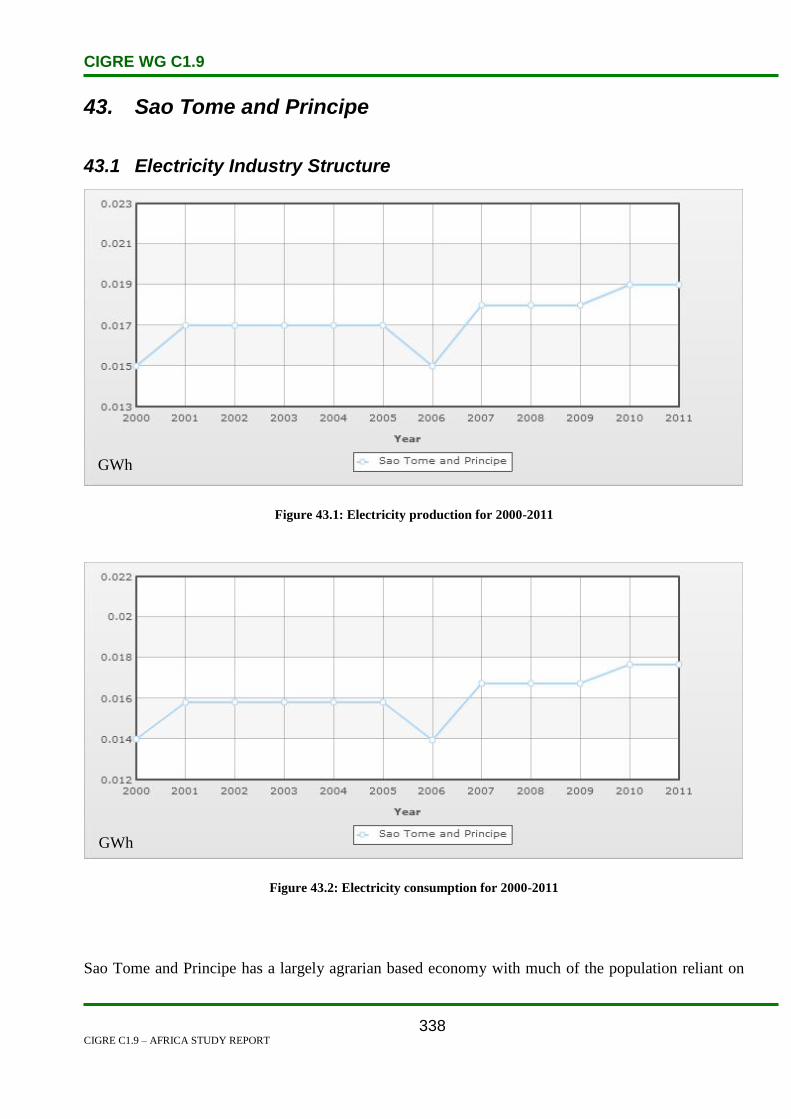
CIGRE WG C1.9
CIGRE C1.9 – AFRICA STUDY REPORT
338
43. Sao Tome and Principe
43.1 Electricity Industry Structure
Figure 43.1: Electricity production for 2000-2011
Figure 43.2: Electricity consumption for 2000-2011
Sao Tome and Principe has a largely agrarian based economy with much of the population reliant on
GWh
GWh

CIGRE WG C1.9
CIGRE C1.9 – AFRICA STUDY REPORT
339
subsistence farming for their livelihood. The country relies heavily upon foreign assistance to fund its
budget and to pay for capital projects. There is very little industry. The main agricultural crop is cocoa.
Tourism is a sector the government has placed a high priority on in order to help offset a large trade
deficit, provide jobs and generate foreign exchange. The government is also hoping that recent
offshore oil exploration will discover commercial deposits. To spur economic growth and
employment, the government has enacted measures to liberalize the economy that include allowing
foreign investors to invest in virtually all sectors of the economy and eliminating public monopolies in
farming, insurance, banking, airlines and telecommunications.
Electrical power is provided by the Empresa de Agua e Electricidade (EMAE), a public-private
companythat is 51% owned by the government, 40% by Sonangol of Angola and 9% by local
investors. Hydropower accounted for 57.9% of electricity production in 2007 and petroleum and diesel
the remainder. About half of the population has access to electricity. Biomass (firewood and charcoal)
is used heavily for cooking purposes.
43.2 Load and Energy Forecasting
Electricity output has risen rapidly in recent years, climbing by 40.2% between 2002 and 2006.
43.3 Planning and Design Criteria
No discussion on planning and design criteria issues was presented.
43.4 Planning Approaches and Methods
No discussion on planning approaches and methods issues was presented.
43.5 Specific Technical Issues
No discussion on planning approaches and methods issues was presented.

CIGRE WG C1.9
CIGRE C1.9 – AFRICA STUDY REPORT
340
43.6 Financial Issues
There is the potential of discovering oil in relatively large quantities given that the country lies in the
oil rich Gulf of Guinea. In 2001, the government signed an agreement with Nigeria concerning the
joint exploration for oil in waters that are claimed by both countries. Under the agreement, a joint
development zone (JDZ) was established and opened for bidding by international oil companies in
April 2003. ChevronTexaco, Exxon Mobil and Equity Energy of Norway were awarded the initial
contracts to search for oil in the JDZ. Nigeria received 60% and Sao Tome and Principe 40% of the
$123 million earned from the bidding process. The initial drilling findings by ChevronTexaco proved
to be disappointing. Addax 6 Petroleum of Switzerland (bought by Sinopec in 2009) also has drilling
operations. On February 16, 2010, the government announced it had awarded an oil concession to
Houston based RHC Energy Inc.[1]
Electrical power is provided by the Empresa de Agua e Electricidade (EMAE), a public-private
company that is 51% owned by the government, 40% by Sonangol of Angola and 9% by local
investors.Hydropower accounted for 57.9% of electricity production in 2007 and petroleum and diesel
the remainder. About half of the population has access to electricity. Biomass (firewood and charcoal)
is used heavily for cooking purposes. [1]
Inmid 2008, Sonangol, the Angolan state oil company, invested EUR2 million to open two gasoline
stations.At the end of 2008, it also signed various agreements worth EUR20 mn in the energy field.
PortugalTelecom has interests in the telecommunication sector.[1]
43.7 Human Resources
No discussion on planning approaches and methods issues was presented.
43.8 References
1. www.estandardsforum.org
2. CIA World Factbook

CIGRE WG C1.9
CIGRE C1.9 – AFRICA STUDY REPORT
341
44. Senegal
44.1 Electricity Industry Structure
The Republic of Senegal, is south of the Senegal River in western Africa. Senegal is bounded by the
Atlantic Ocean to the west, Mauritania to the north, Mali to the east and Guinea and Guinea-Bissau to
the south. Its size is almost 197 000 km2 with an estimated population of 11 700 000. About a third of
the population lives below the international poverty line of US$1.25 a day. Figure 44.1 shows the map
of the transmission and distribution network of Senegal [15].
Figure 44.1: Transmission and Distribution Network of Senegal [15]
Industry Structure
Following institutional reform in 1998, Senegal’s electricity sector was split into three entities:
Société National d’Eléctricité du Sénégal (SENELEC) the national utility.
The Agency for Rural Electrification (ASERA).
The Electricity Regulatory Board (ERB).

CIGRE WG C1.9
CIGRE C1.9 – AFRICA STUDY REPORT
342
SENELEC is the state-owned utility responsible for the transmission and distribution of electricity in
Senegal. It also owns and operates many power stations. Since July 2002, SENELEC has also
received power from the Organisation pour la Mise en Valeur du Fleuve Senegal (OMVS) (Senegal
River Development Organization) generated by the Manantali Hydro Plant. Société de Gestion
del’Energie du Manantali (SOGEM) owns the Manantali plant and 1200 km of 225 kV transmission
line that transports power to Senegal, Mauritania and Mali [1].
Privatization in Senegal has been fraught with obstacles. The central utility operates a single buyer
system, purchasing from private producers. The General Electric/GTI Dakar Independent Power
Producer (IPP), supplies approximately 20% of SENELECs electricity requirements. The second IPP
is Kounoune1 which was partially funded by the International Finance Corporation. The regulator in
Senegal is called the Commission de Regulation du Secteur de Electricite (CRSE) [2].
The CRSE is an independent authority, and is in charge of the regulation of the production activities,
transport, distribution and sale of electrical energy. It also has advisory responsibilities to the Minister
in charge of Energy. For this reason, it investigates licence and concession requests and ensures
compliance with the regulations, determines the structure and the composition of the tariffs, and
advises the Minister in charge of energy on the legislation and draft legislation projects. The CRSE
takes care of the safeguarding of consumer interests, and protects their rights with regard to the price,
supply, and the quality of service of electricity [5].
In Senegal, the public stakeholders operating in the electricity sector are [15]:
The Ministry of Energy, which plays a technical supervisory role through its National Energy
Management, and is responsible for formulating the general policy of the sector, the definition
of the national electrification plan and the standards applicable to the sector. The Minister
issues licenses and contracts on the advice of the CRSE. It authorizes electricity importation
and exportation into and out of Senegal. It fixes electricity tariffs in consultation with the
CRSE.
The Rural Electrification Agency (ASER), which is charged with promoting rural electrification
and is responsible for:
o Designing the rural electrification programme,
o Selecting operators, and awarding contracts in collaboration with CRSE,
o Assisting operators technically and financially, and
o Monitoring the implementation of priority programmes.

CIGRE WG C1.9
CIGRE C1.9 – AFRICA STUDY REPORT
343
The key operators in the development and management of electric power generation, transmission,
distribution and marketing infrastructures are [15]:
SENELEC, which is a limited liability company, the capital of which is exclusively owned by
the Senegalese state. It has a monopoly on transmission throughout the country and is the sole
buyer from independent power producers (IPPs). Under the lease agreement, large scale clients
have been able to buy directly from independent producers since 2008. SENELEC exercises a
monopoly on electricity distribution and marketing within the boundaries granted to it. In 1999,
SENELEC was privatized in conformity with Act No. 98-06, and acquired a strategic partner
(Elyo/Hydro Québec) relinquishing 34% of its capital. After an eighteen month privatization
without attaining the targets set, the Senegalese Government and its partner amicably agreed to
terminate the contract in January 2001. The second attempt at privatization in 2002 was not
successful at the phase of invitation to tender. But the Government re-affirmed in its ‘Lettre de
Politique de Développement du Secteur de l’Energie’ (LPDSE), its intention to carry on with
the liberalization of the sector.
ESKOM Energie Manantali (EEM) has an operation lease for the Manantali hydro-electric
power plant in Mali and for the 225 kV interconnecting power line. These facilities are jointly
owned by the OMVS member countries (Mali, Mauritania and Senegal) and the energy is
shared according to the following quota: 33% for Senegal, 52% for Mali and 15% for
Mauritania.
Greenwich Turbine Inc (GTI) is an independent producer which sells its energy to SENELEC.
Its first contract was awarded in 1996 and in 2000 GTI installed a 52 MW power plant in a
build, own, operate and transfer (BOOT) type agreement for a duration of 15 years. It sells to
SENELEC.
Aggreko International Group installed a power plant of 48 MW capacity in 2005 and signed a
leasing contract with SENELEC as the exclusive buyer of its production. Under the agreement,
SENELEC should supply it with the generation fuel.
Apart from the self-producers and independent producers, SENELEC also buys from the
Industries Chimiques du Sénégal (ICS), Sococim and Sonacos de Zinguinchor.
Private operators who have operation contracts with ASER, whose implementation policy is
defined in the Senegalese action plan for rural electrification – ‘Plan d’Action Sénégalais
d’Electrification Rurale’ (PASER).

CIGRE WG C1.9
CIGRE C1.9 – AFRICA STUDY REPORT
344
Transmission
Figure 42.2 shows the existing and planned transmission network. The network is centered around
Dakar, but isolated distribution networks also exist at Tambacounda and Ziguinchor. To accommodate
the power requirements of the Dakar area, SENELEC plans to create two 90 kV loops around Dakar
and five new 90/30 kV substations. SENELEC also plans to extend the 225 kV transmission network
from Tobene via Touba to Kaolack in the short term, in part to replace the old, expensive diesel units
at the Kahone power station. SENELEC plans to connect Tambacounda to the main transmission
network in 2010, and Ziguinchor in 2008 [1].
Figure 44.2: Senegal Existing and Planned Transmission Network [1]
44.2 Load and Energy Forecasting
SENELEC prepared a Master Plan for Generation and Transmission 2000–2015 in May 2000.
Table 42.1 shows the current SENELEC demand forecast.
Grid-connected energy demand is expected to rise at an average 7.9% per year, from 2 395 GWh in
2006 to 6 285 GWh in 2020. Peak demand is similarly expected to increase from 405 MW in 2006 to

CIGRE WG C1.9
CIGRE C1.9 – AFRICA STUDY REPORT
345
1057 MW in 2020. An average growth rate is assumed of 7% for peak capacity and 7.2% for energy
[15].
SENELEC is also planning to use only interconnected networks by the year 2015 and not to be using
non interconnected networks.
Table 44.1: Senegal Electricity Demand Forecast [15]
2006 2007 2008 2009 2010 2015 2020 Agr
(%)
Capacity (MW)
Interconnected Network
(IN)
390.7 413.8 444.1 388.4 525.9 784.7 1056.6 7.7%
Non Interconnected
Network
14.6 15.9 17.3 5.4 5.9 0.0 0.0
Total 405.3 429.7 461.4 493.9 531.8 784.7 1056.6 7.0%
Energy (GWh)
Interconnected Network
IN
2323.9 2461.2 2641.4 2905.3 3128.0 4667.5 6284.6 7.7%
Non Interconnected
Network
71.2 77.3 84.1 26.8 29.4 0.0 0.0
Total 2395.1 2538.5 2725.5 2932.1 3157.4 4667.5 6284.6 7.2%
Generation
SENELEC’s actual generation installations are allocated between the interconnected network with a
total capacity of 358.9 MW, and the non-interconnected network with a total capacity of 37.6 MW. As
a whole, these installations did not expand in 2005, in contrast with the generating capacity of
SENELEC which increased with the commissioning of the Aggreko leased power installation of 48
MW. The available capacity is 457.6 MW.
The structure of the installed capacity of the SENELEC electric power system is shown in Table 44.1
The installed generation capacity including type of generation is shown in Table 44.2
The existing and planned installed generation capacities are shown in Figure 44.3.
Table 44.2: Distribution of Installed Capacity of SENELEC Power System [15]
Source of Generation Installed Capacity
(MW)
Participation (%)
Own Installation of SENELEC 396.5 70.5%
Manantali Hydro Power Station 66 11.7%
GTI Private Power Plant 52 9.2%
Aggreko Leased Power Plant 48 806%
Total 562.5 100%

CIGRE WG C1.9
CIGRE C1.9 – AFRICA STUDY REPORT
346
Table 44.3: Generation Installation and Installed Capacity (MW) of SENELEC in 2005 [15]
Power Plant Company Type Date of
Commissioning
Installed
Capacity
MW
Bel-air, C1 SENELEC Diesel 1990 9
Bel-air, C2 SENELEC Steam Turbine 1953, 1955, 1959
and 1961
51.2
Bel-air, C2 SENELEC Gas Fired Turbine 1999 35
Cap des biches, C3 SENELEC Steam Turbine 1966, 1975 and
1978
87.5
Cap des biches, C3 SENELEC Gas Fired Turbine 1984 and 1994 60
Cap des biches, C4 SENELEC Diesel 1990/97 and 2003 91
Cap des biches, IPP GTI GTI Combined Cycle 1999 and 2000 52
Cap des biches, Aggreko Aggreko Diesel 2005 48
Saint Louis SENELEC Diesel 1979 6
Kahone SENELEC Diesel 1982 and 1988 18.8
Boutoude SENELEC Diesel 1984, 1986, 1999
and 2006
15.2
Tambacounda SENELEC Diesel 7
Centres Isoles SENELEC Diesel 15.4
Manantali SOGEM Hydro 2002 66
Total 562.1
SENELEC is planning to eliminate non interconnected network by 2015. The demand forecast is
expected to grow to 785 MW during the same year.
Existing and Planned Thermal Generation
0
200
400
600
800
2002 2004 2006 2008 2010 2012 2014 2016
Years
Lo
ad
(M
W)
Installed Capacity
Figure 44.3: Existing and Planned Thermal Generation [1]

CIGRE WG C1.9
CIGRE C1.9 – AFRICA STUDY REPORT
347
44.3 Planning and Design Criteria
The system rated frequency is 50 Hz with an authorized variation ±5%. The nominal low voltage is
127/220 V or 220/380 V according to the requirements. The authorized voltage variation in normal
service is ±5% of the nominal voltage for high voltage (HV) and medium voltage (MV), and ±10% for
low voltage (LV).
The network cannot meet the N-1 criterion at the moment, but there are planned interconnectors that
will help to address this and these are described under Specific Technical Issues.
44.4 Planning Approaches and Methods
The CRSE and ASER are in charge of the regulation of the production activities. Also included in this
law was the creation of an autonomous Regulatory Commission to manage a system of electricity
sector licenses and concessions. This law also created the Senegalese Agency for Rural Electrification
(ASER), to guarantee co-operation between electric companies and private interests, particularly in the
provision of technical and financial assistance related to rural electrification projects.
The ASER develops electrification programmes as defined under the Ministry of Energy’s overall
strategy. Senegal has placed emphasis on the incorporation of renewable energy in its national
electricity production, especially solar energy. The implementation of 5 solar energy projects is
envisaged[3].
For this reason, it investigates requests for licenses and concessions, ensures compliance with the
regulations, determines the structure and composition of the tariffs, and advises the Minister in charge
of Energy on the legislation and draft legislation projects.
The Commission of Regulation of the Sector of Electricity is responsible for the safeguarding of the
interests of the consumers, and protecting their rights with regard to the price, supply and the quality of
service of electricity [5].
SENELEC plans for generation capacity requirements and extensions of the transmission network.
44.5 Specific Technical Issues
According to Senegal has suffered in recent years from massive blackouts due to fuel shortages.
Urgent measures have been taken with the help of the international community in order to return the
national electricity system to normal operation. These measures include the shipment of fuel to
Senegal’s national power company SENELEC, construction of fuel storage facilities and the
examination of the feasibility of building a new oil terminal in Senegal. The African Development
Bank (ADB) recently approved a US$10 million loan to finance the construction of Kounoune thermal

CIGRE WG C1.9
CIGRE C1.9 – AFRICA STUDY REPORT
348
power project, which is expected to help meet the county’s growing demand for electricity [19].
SENELEC is dealing with a chronic production gap, which has worsened due to an increased demand.
The average demand increase during 2005–2009 is estimated at 7%, representing an electricity
consumption of 1.993TWh in 2005 compared to an estimate of 2.66TWh in 2009.
SENELEC is experiencing declining electricity supply reliability due to aging power plants.
SENELEC’s operating costs and financial expenses rose considerably by 35.28% and 40.29% for the
2004 and 2005 fiscal years respectively. According to SENELEC this increase is attributed to the
soaring price of petroleum products and the renting of generators to increase energy supply at the
expense of profitability [15].
Senegal has embarked on an aggressive effort to produce significant quantities of biofuels, initially to
run electricity generation units, and has a pilot project using sugarcane-based ethanol [11].
One quarter of the population in Senegal has access to electricity. In urban areas, the percentage rises
to 50% but drops as low as 5% among the rural population. Only 250 of the 13 000 villages in Senegal
are electrified. In those areas, only 25% of households are actually connected to the grid, as financial
or infrastructural constraints prohibit access by the greater population [3].
The Government of Senegal initiated a project with assistance from the World Bank’s Africa
Traditional Energy Program, to meet an important part of the rapidly growing demand for household
fuels without an associated loss in forest cover and biodiversity and increased greenhouse gas
emissions. Specifically, the project is encouraging community management of forests, promoting
interfuel substitution and improved stoves, and strengthening relevant institutions. The project is being
implemented by Senegal’s Ministry of Environment and Protection of Nature as well as the Ministry of
Industry and Energy [13].
In the final report of the Transmission Stability Study for the Economic Community of West African
States (ECOWAS), certain projects were proposed in the report to be done by 2011 which included
Senegal. The cost of the proposed project for Senegal was estimated at US$122 million. The study is
for the benefit of ECOWAS member countries, United States of America International Donor
(USAID), lenders and other donors. The Organisation pour la Mise en Valeur du Fleuve Gambie
(OMVG) network will provide the first ever link between the coastal countries of Senegal, Gambia,
Guinea Bissau and Guinea, and will make possible long distance energy exchanges all the way from
Conakry to Dakar. The benefits of the OMVG network arise from the following:
The reduction in reserve capacity that would be needed in each participating country to meet the
required standard of reliability.
The substitution of high-cost generation in Gambia and Guinea Bissau with lower-cost power

CIGRE WG C1.9
CIGRE C1.9 – AFRICA STUDY REPORT
349
from Senegal and Guinea.
The extension of the grid supply network to displace high cost local generating plants that are
less efficient and often burn more expensive fuel (diesel) than grid-connected power stations
which burn heavy fuel oil (HFO), or hydro stations [14].
SENELEC’s network is connected at Tobene to the 225 kV OMVS line, which transmits power from
the Manantali hydro plant. The Coyne et Bellier feasibility study report on Felou proposes that the
best solution to implement the N-1 criterion for the OMVS transmission line would be to develop the
southern 225 kV branch Kayes-Tambacounda-Kaolack. That route will offer better reliability securing
energy transmission from Manantali to western Senegal [1]. This route offers the following
advantages:
Better reliability, securing energy transmission from Manantali to western Senegal.
Lower transmission losses.
Better system stability, reinforcing the network between Bamako, Dakar and Nouakchott.
Link with the proposed northern loop of the OMVG network, which also includes a section
from Tambacounda to Kaolack.
The Zone B interconnected network (Mali, Senegal and Mauritania) is adequate to carry the existing
load, however the 225 kV OMVS line is close to its limit at 80% loading. An N-1 contingency
involving the OMVS line is serious and leads to system divergence [14].
44.6 Financing Issues
Recent policy is for new power projects to be built by IPPs, following on from the 50 MW GTI
combined cycle power station, which was completed in 2000. The 2000 Master Plan envisages total
new net capacity to be commissioned over the period 2005 to 2015 of 464 MW of thermal plant, plus
contributions of 75 MW from three hydro projects (Felou, Sambangalou and Gouina) and 41 MW of
small diesel projects. The May 2000 Master Plan identified diesel plants, fuelled by heavy fuel oil, to
be the cheapest new thermal generation option for both peaking/reserve and base load application [1].
Some work on expansions affecting Senegal has been carried out with the help of USAID. An
example of this is the work leading to the proposed 1 677 km, 225 kV, transmission line
interconnecting the national power systems of The Gambia, Guinea, Guinea Bissau and Senegal. Pre-
investment studies had rendered the project techno-economically feasible with mitigable
environmental and social impacts. Projected commissioning of the project is within the period 2011–
2012 [17].

CIGRE WG C1.9
CIGRE C1.9 – AFRICA STUDY REPORT
350
44.7 Human Resource Issues
SENELEC is doing its own generation, transmission and distribution planning. However, some
external consultants do carry out some work affecting network expansion in Senegal. The following
are examples of work carried out by external consultants:
Nexant, for planning studies for the use of USAID and ECOWAS [1]. The Regional
Transmission Study evaluates the new cross-border transmission projects that are proposed for
the West Africa interconnected power system over the 2004 to 2020 planning horizon, which is
for the benefit of ECOWAS member countries, USAID, lenders and other donors.
Asilea Resources LCC, for scope of work including assisting SENELEC with:
o drafting documentation for requests for proposals (RFP). The documents include:
The Terms and Conditions for bidders.
the Technical Specifications.
Power Purchase Agreements (PPAs).
Applications for the support of the World Bank Group (IFC and IDA/Partial
Risk Guarantee – PRG).
o Electricity tariff structuring, the fuel market and availability.
o Meetings with the bidders, site visit and visits to fuel facilities[18].
44.8 References
1. Final Report ‘West Africa Regional Transmission Stability Study’. Volume 2: Master Plan.
2. Wikipedia
3. www.areed.org/country/senegal/senegal.pdf
4. www.SENELEC.sn
5. www.crse.sn/pdf/carteElectriciteSenegal.pdf
6. www.gefweb.org/work_Programs/wp_febol/senegal_energy_conversetion.pdf
7. Assessing the Impact of Privatization in Africa
8. Volume 3 ‘Stability Study and Operational Analysis – Final’
9. http://books.google.co.za/books?id=dg2mhydirtKkc&pg
10. http://www.gnesd.org/downloadables/Energy_Access_I/Technical_report_ENDA_ver_16_
April_2004.pdf
11. http://en.Wikipedia.org/wiki/Energy_in_Senegal
12. www.absenergyreseach.com
CIGRE WG C1.9
CIGRE C1.9 – AFRICA STUDY REPORT
351
13. http://www.gefweb.org/Outreach/outreach-PUblications/Project_factsheet/Senegal-sust-1-
cc-wb-eng-ld.pdf.
14. Final Report ‘West Africa Regional Transmission Stability Study’. Project summary report.
August 2004.
15. http://www.ecowapp.org/WAPP%20PDFS/KPI-ENG.pdf
16. http://www.usaid.gov/locations/sub-saharan_africa/countries/senegal/
17. http://www.ecowapp.org/Reports/11th_dcm.pdf
18. http://www.asilea.com/projects_pv.htm
19. http://www.eia.doe.gov/emeu/cabs/ECOWAs/full.html

CIGRE WG C1.9
CIGRE C1.9 – AFRICA STUDY REPORT
352
45. Seychelles
45.1 Electricity Industry Structure
Seychelles is composed of 115 islands that are located in the Indian Ocean 1 100 km northeast of
Madagascar. Most of the population lives on three islands; Mahe, which is the largest island, Praslin,
and Digue. The total land area of all the islands is just two and a half times that of Washington DC.
Seychelles is the smallest country in Africa and the 14th
smallest country in the world. The climate is
tropical. There is little temperature variation during the year. The average annual temperature is 79.5
degrees. The rainiest months are from November to February. The population is 89 188 (US Census
Bureau estimate for 2011) and the population density is 196 per sq. km.
Seychelles has no indigenous sources of coal, oil, natural gas and hydropower. Oil imports are about 7
000 barrels a day. There is no oil refinery and as a result all petroleum refined products such as
kerosene, jet fuel, gasoline and diesel have to be imported. There are three diesel power plants, two of
which are on Mahé that generate all the electricity. PUC has a monopoly on generating and
transmitting electricity. The electrification rate is close to 100%. The electric supply is dependable.
In April, the Seychelles Petroleum Company, a state-owned entity, signed an agreement with Fugro
Data Service AG of Switzerland, and Geomahakarsa of Hong Kong, to conduct offshore seismic tests
to determine if there are any exploitable offshore oil deposits. Houston-based PetroQuest International
has signed an off-shore oil production sharing agreement with the government but has failed to find
any commercial deposits. East African Exploration, a subsidiary of Dubai-based Black Marlin Energy,
has also been searching for oil without success in a joint venture with Avana Petroleum of the UK [1].
The PUC Electricity Division is made up of two main sections namely Generation Section and
Transmission & Distribution Section[2].
The Generation Section is responsible for the safe and continuous production of electricity from four
generating stations. The stations, which are all managed by the section consist of diesel-based
generators and are situated on the islands of Mahe and Praslin.
The Electricity Transmission & Distribution Section is responsible for transmission and distribution of
electricity within the Republic of Seychelles. The section manages an integrated 33-kV/11-kV
distribution network on the island of Mahe and 11 kV network on the island of Praslin and La Digue.
In addition, it provides an inspectorate service to the public in order to ensure that a high standard of
electrical components are maintained in all installations.
From the early 1960's, the electricity supply system has occupied a position of continually increasing
importance in the development of the Seychelles. Since then, this system has developed to become a

CIGRE WG C1.9
CIGRE C1.9 – AFRICA STUDY REPORT
353
complex network which supplies electric power to Mahe, Praslin and the inner islands.
The Electricity Division of the PUC is responsible for the generation, transmission and distribution of
the electricity supply in Seychelles. The Division has the crucial task of maintaining an efficient,
coordinated and economical system of electricity supply paying due regard to the environment and
consumer's requests.
This is achieved through the management of three diesel-generating stations and 11 kV and 33 kV
networks extending over 395 km.
The Division comprises of a Generation Section and a Transmission and Distribution Section.
Generation
The Generation section is responsible for electricity production for Mahe, Praslin, La Digue and the
inner islands only. The section's main objectives are to produce safer, more reliable and economical
sources of electricity to meet the country's requirements.
On Mahe, there are two power plants: Power Station B, located at New Port, and Power Station C,
located at Roche Caiman. The country's first power plant, Power Station A, is located at Huteau Lane
and is no longer in service. Power Stations B and C are tasked with generating the required electricity
supply for Mahe as well as the inner islands.
On Praslin, there is one power plant, located at Baie Ste. Anne. This power plant supplies Praslin, La
Digue, Ile Ronde and Ile Chauve-Souris.
Transmission & Distribution
The Transmission and Distribution section is responsible for the transmission and distribution of
electrical power on Mahe, Praslin, La Digue and the inner islands. The main objectives are to transmit
bulk electrical power over long distances and to redistribute this power safely and reliably to all
consumers.
Transmission of electrical power is achieved through the 33 kV network. This network transmits
electrical power at a voltage of 33 kV from Power Stations B and C to the 33 kV substation at Anse
Boileau. From there, the voltage is stepped down to the 11 kV required for distribution through means
of 33 kV / 11 kV transformers.
Distribution of electrical power is achieved through means of the 11 kV network which extends around
the islands. This 11 kV supply is further stepped down to a lower voltage and the vast majority of
consumers are connected at this lower voltage through means of distribution substations and their
associated low voltage networks.
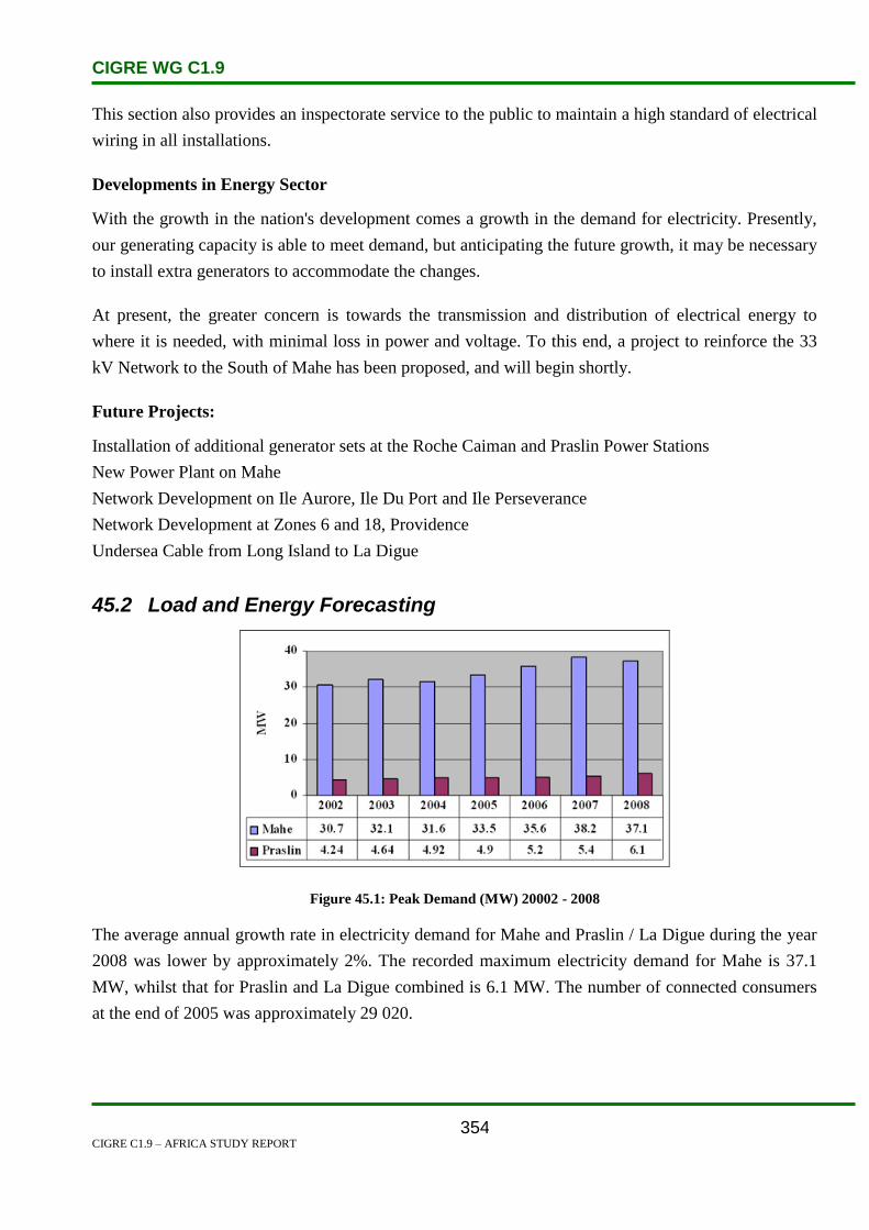
CIGRE WG C1.9
CIGRE C1.9 – AFRICA STUDY REPORT
354
This section also provides an inspectorate service to the public to maintain a high standard of electrical
wiring in all installations.
Developments in Energy Sector
With the growth in the nation's development comes a growth in the demand for electricity. Presently,
our generating capacity is able to meet demand, but anticipating the future growth, it may be necessary
to install extra generators to accommodate the changes.
At present, the greater concern is towards the transmission and distribution of electrical energy to
where it is needed, with minimal loss in power and voltage. To this end, a project to reinforce the 33
kV Network to the South of Mahe has been proposed, and will begin shortly.
Future Projects:
Installation of additional generator sets at the Roche Caiman and Praslin Power Stations
New Power Plant on Mahe
Network Development on Ile Aurore, Ile Du Port and Ile Perseverance
Network Development at Zones 6 and 18, Providence
Undersea Cable from Long Island to La Digue
45.2 Load and Energy Forecasting
Figure 45.1: Peak Demand (MW) 20002 - 2008
The average annual growth rate in electricity demand for Mahe and Praslin / La Digue during the year
2008 was lower by approximately 2%. The recorded maximum electricity demand for Mahe is 37.1
MW, whilst that for Praslin and La Digue combined is 6.1 MW. The number of connected consumers
at the end of 2005 was approximately 29 020.

CIGRE WG C1.9
CIGRE C1.9 – AFRICA STUDY REPORT
355
Figure 45.2: Consumption per Category of Customers 2008
45.3 Planning and Design Criteria
South Mahe Electricity Project
The project will entail providing a system to supply power from the electricity generating station at
Roche Caiman to south Mahe by underground cables, which will be less prone to interruptions by
lightning, falling trees and birds. [2]
The project will also cater for future demands in view of increased rate of development. Moreover, the
new system, which will convey 33 kVA of power, will ease the pressure on the existing system, since
the much longer route via San Soucis incurs losses up to 9% of the power transmitted. [2]
The new system will save up to two million units of electricity now being lost, which though adds up
to only 1% of the power, will bring savings of up to 500 000 litres of oil used to generate that
electricity. The project has become necessary due to the increased demand for electrical power with the
ongoing rapid development.[2]
45.4 Planning Approaches and Methods
No discussion on specific technical issues was presented.
45.5 Specific Technical Issues
No discussion on specific technical issues was presented.
45.6 Financing Issues
The United Arab Emirates is providing funding for several infrastructure projects including improving
the road, electricity and water systems, and building a diagnostic center at Victoria hospital.On January
20, 2009, the government signed an agreement with Masdar, a wholly-owned company of the
CIGRE WG C1.9
CIGRE C1.9 – AFRICA STUDY REPORT
356
government of Abu Dhabi, which specializes in the development of wind and solar power, to develop
wind power on Mahé. On October 28, 2009, a feasibility study that will last 12-15 months was
begun.[1]
45.7 Human Resources
No discussion on human resource issues was presented.
45.8 References
1. http://www.estandardsforum.org
2. http://www.puc.sc/

CIGRE WG C1.9
CIGRE C1.9 – AFRICA STUDY REPORT
357
46. Sierra Leone
46.1 Electricity Industry Structure
Figure 46.1: Geographic Map of Sierra Leone [1]
Sierra Leone’s Ministry of Energy and Power has responsibility for the entire electricity sector, and is
the policy making organ of this sector. Its responsibilities also cover harnessing the country’s
considerable hydropower potential, the most notable of which is the Bumbuna Hydroelectric Project
(BHEP), and matters related to alternative energy sources.
The National Power Authority (NPA) is the vertically integrated monopoly supplier of electricity in
the Western Area, where the capital, Freetown, is situated. The NPA is further responsible for the
operation of electricity supply in the provinces. The Bo-Kenema Power Services (BKPS) is a semi-
autonomous division of the NPA, and is responsible for the integrated supply of electricity to the
townships of Bo and Kenema and their environs. Power supply is still grossly inadequate and is
subject to frequent interruptions in Freetown. Oversight of the NPA currently rests with the National
Commission for Privatisation (NCP) pending its eventual privatization [7].
The National Power Authority Act of 1982 established the NPA as the entity with the sole
responsibility for carrying out power (including hydro) generation, transmission and distribution in the
country. The 1993 NPA (Amendment) Act stipulated additional governance duties for the NPA. The
Project Implementation Unit (PIU) for the BHEP reports to the Ministry of Energy and Power. The

CIGRE WG C1.9
CIGRE C1.9 – AFRICA STUDY REPORT
358
NPA forms part of the Technical Committee which oversees the Bumbuna PIU. Operational oversight
of the NPA is provided by a Board, which reports directly to the NCP in preparation for Private Sector
Participation. This will allow for more investment and financial support for projects in the country’s
electrical power sector.
Much of the Sierra Leone’s power generation capacity was hampered during the civil war. The
country currently experiences frequent blackouts in the Freetown peninsula and electricity supply is
available to customers only for a few hours every week. Most areas in the interior of the country are
wholly or largely without access to electricity. About 90% of Sierra Leone’s electricity is consumed in
the country’s four main cities. The capital city of Freetown uses 82% of the country’s electrical
power, followed by Kenema which uses 3%, Bo uses 3%, and Makeni uses 2% [3, 4].
Sierra Leone’s power generation relies substantially on fuel oil imports. Freetown’s electricity supply
comes from the oil-powered Kingtom power generating station, which struggles to provide a
continuous and uninterrupted power supply, due to it being in poor condition. The NPA is responsible
for providing electricity to Sierra Leone. The company was previously named the Sierra Leone
Electricity Corporation (SLEC). In recent years the NPA has been undergoing privatization, allowing
more investment and financial support for projects in the country’s electrical power sector.
There is a substantial interest in developing Sierra Leone’s hydropower potential. A major
hydropower project had been the focus for providing the power needs of the country for a long time.
The Bumbuna Hydroelectric Project (BHP) had been developed in 1970 but civil conflict in the
country caused construction works to be suspended in 1997 when the project was 85 per cent
complete. It was only in June 2005 that the World Bank approved construction to be resumed on the
project. The project entails a hydropower complex, located on the Seli River, in the valleys of the Sula
Mountains, approximately 200 km northeast of Freetown, in the Kalansogoia Chiefdom of the
Tonkolili district. It encompasses an 88 m high rock-fill dam with an asphalted concrete upstream
face; a 50 MW power station housing two turbine-generator units of 25 MW each; a transmission
system consisting of 200 km of 161 kV transmission line from the power station to Freetown and a
substation in Freetown to feed power into the Western Area grid. It includes a separate power service
to Makeni, Lunsar and Port Loko.
The BHP is seen as beneficial to the future of Sierra Leone’s electrical power sector because it can
greatly improve the current power supply situation by providing a reliable supply of electricity that
would meet the electricity needs of the West African country, including Freetown, at the lowest
possible cost and in a sustainable manner. Moreover, the electricity generated by the BHP will provide
power to new towns such as Makeni, Lunsar and Port Loko, which are currently not connected to the
grid. The project was due to be completed by the end of 2007.

CIGRE WG C1.9
CIGRE C1.9 – AFRICA STUDY REPORT
359
46.2 Load and Energy Forecasting
To provide reliable power for the Western Area in the immediate term, independent power producers
(IPPs) must be allowed to generate electricity and sell it in bulk to the National Power Authority
(NPA) for subsequent transmission and distribution to consumers. NPA, in addition to its transmission
and distribution functions, should continue generating electricity utilizing its current stock of
machines, the current state of which is as detailed in the Table 46.6 below [2]:
Table 46.1: Generation Capacity of Kingtom Power Station (November 2006)
Generator Year Installed Installed Capacity
(MW)
Available Capacity
(MW)
Type of Fuel
Mirrlees 2 2006 6.9 6.0 HFO(Heavy Fuel Oil)
Mirrlees 3 2001 6.3 - HFO
Sulzer 4 1978 9.2 5.5 HFO
Sulzer 5 1980 9.2 - HFO
Mitsubishi 1995 5.0 - HFO
Caterpillar 1 2001 1.28 - Diesel
Caterpillar 2 2001 1.28 0.7 Diesel
Total 39.16 12.2
The following activities are envisaged for the medium term (2007–2009) [2]:
The Arab Bank for Economic Development in Africa (BADEA) Project (22.68 MW).
Phase I – the supply, installation and commissioning of one 7.56 MW diesel generating unit
(DGU) at Blackhall Road.
Phase II – the supply, installation and commissioning of two 7.56 MW DGUs.
o The Japan International Cooperation Agency (JICA) Project (10 MW).
o The Japanese Government, via JICA, is on course with the implementation of a 10 MW
(2 X 5 MW) thermal project at the Kingtom Generating Station by the last quarter of
2008.
The Bumbuna Hydroelectric Project (Phase I: 50 MW).
Ninety-five per cent of the dam construction work has been completed for this initial 50 MW
phase. The Government of Sierra Leone has secured a US$10 million loan from the
Organization of Petroleum Exporting Countries (OPEC) for the completion of the 161 kV
transmission line between Bumbuna and Freetown. The entire first phase of the project was
thus expected to be completed by the third quarter of 2007, resulting in a 50 MW generating
capacity in the rainy season and 18 MW in the dry seasons.

CIGRE WG C1.9
CIGRE C1.9 – AFRICA STUDY REPORT
360
During this medium term, the Sulzer 5 generating unit (9.2 MW installed capacity) at the Kingtom
Generating Station, currently being overhauled, is expected to come on stream with an output of about
6 MW. Thus, by 2009, the minimum expected generation in Greater Freetown would be 100 MW.
For a population of about 5 million now, a minimum residential power requirement for the country is
500 MW. Taking population growth and industrialization into account, by 2015 the country should
require at least 1000 MW of generating capacity. In an effort to meet this power requirement, the
following are some of the initiatives envisaged (2010–2015):
The Bumbuna Hydroelectric Project (Potential: 275 MW).
Phase I – current: 50 MW.
Phase II – 40 MW additional installed capacity on the same dam as in Phase I.
Phase III – 90 MW additional installed capacity from an additional dam at Yiben, upstream of
the current.
Phase IV/V – additional installed capacity of 95 MW from both the Bumbuna and Yiben dams.
Thus, total installed capacity at the completion of all phases of the project is expected to be 275
MW during the rainy season and 134 MW during the dry seasons. Phases II to V are estimated
to be completed in 5 to 6 years.
The Bekongor Hydroelectric Project (Potential: 200 MW).
In addition to the above hydro project, Government has revived interest in the development of
the 85 MW Bekongor III hydro project in the Kono district. In the event of Bekongor I, II and
III being developed, an estimated total installed capacity of 200 MW is realizable.
The Bo-Kenema Power Services (BKPS) Goma Hydroelectric Facility (12 MW).
The 4 MW Goma hydroelectric facility operated by the Bo-Kenema Power Services (BKPS),
an autonomous subsidiary of NPA, is expected to be expanded to 12 MW in two phases. The
first phase is expected to be an upgrade of the turbines from 4 MW to 6 MW and the second
phase the construction of a new dam upstream of the current and the installation of additional
turbines to bring the total installed capacity to 12 MW. This upgrade/expansion will be
undertaken by the China National Electric Equipment Corporation (CNEEC).
Thus, by 2015, the expected additional total installed generating capacity countrywide is 519.68 MW
(487 MW hydro; 32.68 MW thermal), broken down as shown in Table 46.7 below.
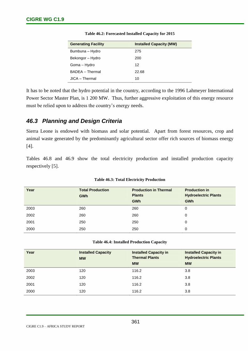
CIGRE WG C1.9
CIGRE C1.9 – AFRICA STUDY REPORT
361
Table 46.2: Forecasted Installed Capacity for 2015
Generating Facility Installed Capacity (MW)
Bumbuna – Hydro 275
Bekongor – Hydro 200
Goma – Hydro 12
BADEA – Thermal 22.68
JICA – Thermal 10
It has to be noted that the hydro potential in the country, according to the 1996 Lahmeyer International
Power Sector Master Plan, is 1 200 MW. Thus, further aggressive exploitation of this energy resource
must be relied upon to address the country’s energy needs.
46.3 Planning and Design Criteria
Sierra Leone is endowed with biomass and solar potential. Apart from forest resources, crop and
animal waste generated by the predominantly agricultural sector offer rich sources of biomass energy
[4].
Tables 46.8 and 46.9 show the total electricity production and installed production capacity
respectively [5].
Table 46.3: Total Electricity Production
Year Total Production
GWh
Production in Thermal
Plants
GWh
Production in
Hydroelectric Plants
GWh
2003 260 260 0
2002 260 260 0
2001 250 250 0
2000 250 250 0
Table 46.4: Installed Production Capacity
Year Installed Capacity
MW
Installed Capacity in
Thermal Plants
MW
Installed Capacity in
Hydroelectric Plants
MW
2003 120 116.2 3.8
2002 120 116.2 3.8
2001 120 116.2 3.8
2000 120 116.2 3.8

CIGRE WG C1.9
CIGRE C1.9 – AFRICA STUDY REPORT
362
The National Power Authority (NPA), the country’s utility established in 1982, is in charge of the
generation, transmission, distribution and supply of electricity. The Kingtom Power Station, currently
the only available generating station in the Western Area, had an installed capacity of 39 MW in 2005
(generating capacity is around 8 MW) and a very poor availability and reliability track-record.
The NPA provides a service to a customer base of 45 000 with nearly 600 employees. The
transmission and distribution network covers an area of 450 km2 and can safely supply 20 MW from a
designed capacity of 36 MW. In 2005, the utility produced 53.5 GWh, a 56% decline from its peak of
123.5 GWh in 2002 (2006 estimates were 24 GWh) [6].
46.4 Planning Approaches and Methods
Less than 10% of Sierra Leone’s population has access to electricity. Most of these live in the western
area around the capital, Freetown. The country’s generating capacity prior to the civil conflict in 1991
was about 120 MW of which 116 MW was from thermal power plants, and 4 MW was from the hydro
plant at Dodo in the Kenema District. Of the total installed capacity, NPA operated 33.4 MW in the
Western area, and 14.5 MW in isolated provincial towns. There was some 28 MW of captive capacity
in the mining sector, and 40 MW of estimated capacity of auto-generators. The available capacity for
generation then in the Western Area was however, significantly less than the installed capacity due to
poor maintenance, a shortage of spare parts and inadequate technical skills of NPA staff.
The captive capacity in the mines and the installed capacity in the provincial towns were all virtually
wiped out during the 10 years conflict. In the Western area, in spite of substantial investment in the
sector since 1991, the situation continues to be desperate. Rural electricity supply has largely been
ignored. Over the past two decades, the Bumbuna Hydroelectric Project has undergone various
implementation stages but has been fraught with difficulties related to finance, the ten-year civil war,
and technical problems. In 2004 this project was about 85% complete.
About 80 per cent of the power generated by NPA is consumed in the Western Area. The consumption
pattern is roughly 70% industrial/commercial, 30% per cent residential. Previous studies have
projected annual growth rates of 4.5% and 7.4% for the Western Area and the provinces respectively.
The state of the power sector indicates that there is a considerable gap between power demand and
supply.
In 1999, ECOWAS Council of Ministers, by Regulation C/Reg.7/12/99, adopted a Master Plan to
develop electricity generation and transmission infrastructure, and to interconnect the national

CIGRE WG C1.9
CIGRE C1.9 – AFRICA STUDY REPORT
363
electrical power systems. Figure 46.2 shows the interconnected countries. The envisaged connections
are as follows [8, 9]:
Coastal Transmission Backbone Sub-program (Côte d’Ivoire, Ghana, Benin/Togo, Nigeria):
Inter-zonal Transmission Hub Sub-program (Burkina Faso, OMVS via Mali, Côte d’Ivoire via
Mali, LSG via Côte d’Ivoire).
North-core Transmission Sub-program (Nigeria, Niger, Burkina Faso, Benin): OMVG/OMVS
Power System Development Sub-program (The Gambia, Guinea, Guinea Bissau, Mali,
Senegal).
Liberia-Sierra Leone-Guinea Power System Re-development Sub-program (Côte d’Ivoire,
Liberia, Sierra Leone, Guinea).
Figure 46.2: Interconnected Countries
SENEGAL
GUINEA BISSAU GUINEA
SIERRA LEONE
MALI
LIBERIA
GAMBIA

CIGRE WG C1.9
CIGRE C1.9 – AFRICA STUDY REPORT
364
46.5 Specific Technical Issues
Ongoing theft of overhead and underground cables has greatly hampered the transmission and
distribution of electricity, especially in the east end of Freetown. The replacement cost of the stolen
materials is estimated at US$200 000. The Ministry of Energy & Power and the NPA are currently
devising a robust action plan involving the police to address this problem.
Central to the achievement of the foregoing energy access goals, is the utilization of indigenous energy
resources of a renewable nature. In that respect, now that the NPA no longer has a monopoly over
energy service provision in the country, private sector financing or public-private partnerships should
be vigorously pursued for the establishment of solar home systems (for lighting, water pumping, etc.),
the implementation of biogas digesters (for cooking, lighting and motive power applications), and the
establishment of windmills (for lighting, water pumping, etc.), for homes, schools, hospitals,
community centres, etc. across the country,. Even commercial houses and industrial establishments
must be encouraged to embark upon this ‘green path’ to sustainable development. And given the
hydro potential in the country (1 200 MW), small hydro schemes must be resorted to for far-flung rural
communities. The exploitation of such small hydro schemes will lead to rural industrialization and
hence employment, poverty reduction and sustainable development [2].
46.6 Financing Issues
Despite the infusion of a considerable amount of capital to improve the electricity situation, NPA’s
underlying problems still exist. The utility has made a loss after tax for the last ten years. The
unaudited draft financial statement for 2003 indicates a loss for the year of Le19.4 billion or US$7.7
million. The accumulated loss at the end of the year was Le105.5 billion or US$42.2 million. The
government has given subsidies to meet capital and operating requirements. The capital subsidies
however are very insignificant relative to the capital requirements of the utility [7].
In 2007 there was poor commercial performance, due to the low reliability of public mains supply.
Revenues in 2005 fell to US$ 8.6 million, equivalent to a 36% decrease from its level in 2003. Net
income has been consistently negative, averaging US$ 8.1 million over the last five years. Cost-
recovery tariffs were introduced ahead of the Bumbuna completion with the hope of greatly improving
the financial performance. The Commercial Department struggles to collect revenue and outstanding
debt remains very high. The present level of non-technical losses (theft) is around 20% and is clearly
unacceptable. Prepayment meters, meter test facilities and the establishment of new Customer Service
Centres are seen as key solutions [6].
The major expected impediment to the exploitation of the country’s hydro potential is funding.
However, with the coming into force of the NPA (Amendment) Act, 2006, on 31 March 2005, this

CIGRE WG C1.9
CIGRE C1.9 – AFRICA STUDY REPORT
365
funding constraint may very well be addressed by the fact that the monopoly of the NPA over the
generation, transmission, distribution and other related activities was repealed under that Act. Thus,
private sector and/or public-private financing of such hydro projects is now possible and should be
aggressively pursued [2].
The inability of Government to provide its own financial contribution to the current phase of the
Bumbuna project has necessitated the acquisition of a commercial loan for which a partial risk
guarantee (PRG), with its attendant conditions, is being provided by the World Bank.
The on-going financing is as follows [6]:
Sierra Leone Power and Water Project: IDA Credit US$20 million covers institutional
development, regulatory development, legal frameworks for sector, capacity-building,
rehabilitation and maintenance. Under this credit, the Government of Sierra Leone (GoSL),
with support from the National Commission for Privatization (NCP) and its advisers, are
preparing terms of reference for a transaction adviser to prepare a Management Contract (to
commence in January 2008) to support NPA management and operations and effectively take
over the day to day management of the NPA.
Government of the Republic of South Africa: Acquisition and installation of a 6.9 MW diesel
generating unit at the Kingtom Power Station which has been installed and pre-commissioned.
A new cooling tower has been purchased to improve cooling (operational in April 2007).
Arab Bank for Economic Development in Africa (BADEA) and the Saudi Development Fund
(SDF). Acquisition of 3 x 7.56 MW diesel generating units to be installed at the Blackhall
Road site in mid 2008.
Japan International Cooperation Agency (JICA). Supply of 2 x 5 MW units (expected
commissioning by mid 2009 – awaiting Japanese Government approval). Estimated cost is
approximately US$10 million to be commissioned mid 2009. Key elements of this assistance
include: 2 x 5 MW generating sets at the Kingtom Power Station; new 33 kV sub-station at
Regent; new 33 kV lines between Wilberforce and the Regent sub-station; new 11 kV lines
between Kingtom and Wilberforce, on the one hand, and between Falconbridge and Blackhall
Road on the other.
46.7 Human Resources
Staffing at NPA currently stands at over 600. A recent study by NPA indicated that 241 were
considered suitable for retrenchment (‘dormant’ staff) at a cost of approximately 5 billion Leones [6].

CIGRE WG C1.9
CIGRE C1.9 – AFRICA STUDY REPORT
366
‘The shortfall of health personnel continues to represent one of the major constraints to the
development of health services and access to basic health care in Sierra Leone. This is against a
background of increased demands for health care from various stakeholders, a shrinking budget against
high expectations from the public for quality health care. Sierra Leone has implemented health human
resource policies and plans to chart the course for a coherent resolution of major human resources
problems and puts in place a framework to facilitate decision making in the human resources arena.
The HRH Global Resource Center provides hosting services for two of the HRH policy and planning
documents for the Ministry of Health and Sanitation of Sierra Leone:
Sierra Leone Human Resource for Health Development Plan 2006–2010
This plan contains an analysis of the current situation with a focus on the distribution of Health
Personnel, the current stock, wastage, outputs from training schools, dropout rates and human
resources policies currently in place in the Ministry of Health and Sanitation. It also projects future
requirements based on the recommended establishment.‘ [10]
46.8 References
1. http://geography.about.com/library/cia/blcsierraleone.htm
2. http://siteresources.worldbank.org/SIERRALEONEEXTN/Resources/SL_Energy_Sector_.
3. http://www.mbendi.com/indy/powr/af/sl/p0005.htm
4. http://www.energyrecipes.org/reports/genericData/Africa/061129%20RECIPES%20countr
y%20info%20Sierra%20Leone.pdf
5. http://www.iaea.org/inisnkm/nkm/aws/eedrb/data/SL-elich.html
6. http://www.daco-
sl.org/encyclopedia/2_coord/2_3/1Qtr_4_DEPAC_energypresentation07.ppt
7. http://www.uneca.org/eca_resources/Conference_Reports_and_Other_Documents/sdd/cem
mats_study.pdf
8. http://www.africa-investor.com/presentations/
9. http://www.narucpartnerships.org/Documents/Amadeos%20Presentation.ppt
10. http://www.hrhresourcecenter.org/sierra_leone_policies

CIGRE WG C1.9
CIGRE C1.9 – AFRICA STUDY REPORT
367
47. Somalia
47.1 Electricity Industry Structure
Somalia is located in eastern Africa bordering with Ethiopia, Kenya and Djibouti, the Gulf of Aden
and the Indian Ocean. Total land area of 637 660 km², population estimated at 12 million (2002), and
GDP real growth rate of 2.4% (2005).
Virtually all operational plants are of the thermal type (diesel powered generator sets). Ethiopia is
trying to be neighbourly by helping with supply to a few towns along her border. But until there is a
permanent administrative government, instead of the free for all that currently exists, we do not see
any long term stability in the supply of electricity in this environment.
Figure 47.1: A map of Somalia
(Source: EIA)
In 1992, responding to the political chaos and humanitarian disaster in Somalia, the United States and
other nations launched peacekeeping operations to create an environment in which assistance could be
delivered to the Somali people. By March 1993, the potential for mass starvation in Somalia had been
overcome, but the security situation remained fragile. On 3 October 1993 U.S. troops received
significant causalities (19 dead over 80 others wounded) in a battle with Somali gunmen. When the
United States (in 1994) and the UN withdrew (in 1995) their forces from Somalia, after suffering
significant casualties, order still had not been restored.
The United States has no formal relations with Somalia. Somalia has not had a functioning national
government since 1991 and presently has no constitution in force. In February 2004, a Transitional
Federal Charter was established which could serve as the basis for a future constitution. In August
2004, the Somali Transitional Federal Authority (TFA) was established as part of the Somalia National

CIGRE WG C1.9
CIGRE C1.9 – AFRICA STUDY REPORT
368
Reconciliation Conference. The Somalia National Reconciliation Conference concluded after it elected
a Transitional President in October 2004.
The current attempt to form a national government follows another structure which was tried in 2000.
The Transitional National Government (TNG) was created in October 2000 with the three-year
mandate of creating a permanent national Somali government. Although they declared their
independence, the TNG did not recognize Somaliland and Puntland as independent republics and was
unable to reunite the country. Somaliland refused to participate in peace talks with TNG, saying that
while it would welcome peace in former Italian Somalia, Somaliland is an independent country
Somalia is unable to receive International Monetary Fund (IMF) and other multilateral aid due to the
lack of institutions or financial infrastructure in place. In 2005, Somalia had an estimated gross
domestic product (GDP) growth of 5.7 per cent. A GDP increase of 2.6 per cent was the forecast for
2006. [1]
Oil and Natural Gas
Somalia has no proven oil reserves, and only 200 billion cubic feet of proven natural gas reserves.
Somalia currently has no hydrocarbon production. Oil seeps were first identified by Italian and British
geologists during the colonial era. Exploration activities were focused in northern Somalia, and several
foreign firms, including Agip, Amoco, Chevron, Conoco and Phillips, held concessions in the area.
The firms all declared force majeure following the collapse of the central government.
Exploration activity remains hindered by the internal security situation and the multiple sovereignty
issues. In February 2001 Total signed an exploration agreement with the Transitional National
Government (TNG). The twelve-month agreement granted Total the rights to explore in the Indian
Ocean off southern Somalia. Hassan Farah, TNG’s Minister for Water and Mineral Resources, stated
that the government would provide security during the exploration activities. Several factional leaders
denounced the agreement, and stated that the TNG did not have the authority to sanction the
agreement, nor the power to guarantee the safety and security of the exploration operations.
In May 2001, Somaliland signed an agreement with UK-registered Rovagold and two Chinese firms,
CPEC and CPC, for the right to explore for oil. Dubai-based Zarara Energy also signed an exploration
agreement with Somaliland. The Somaliland government has said it will honor, until they expire, the
existing contracts foreign companies signed with the Barre regime that are in their territory. None of
the firms have resumed operations in Somaliland.
Somalia’s petroleum consumption was an estimated 6 000 barrels per day (bbl/d) in 2005. The
organization officially responsible for all petroleum product distribution and retailing is the
cooperative Iskash. The state-owned Iraqsoma Refinery Corporation had operated a 10 000-bbl/d

CIGRE WG C1.9
CIGRE C1.9 – AFRICA STUDY REPORT
369
refinery outside of Mogadishu, but it has been inoperative since 1991. Total is involved in the
downstream sector in Somaliland. It rehabilitated and manages the operations of the oil terminal in
Berbera, Somaliland’s primary port. Total also supplies fuel to airports located in Berbera and
Somaliland’s capital of Hargeisa. [1]
Electricity
Somalia currently has installed electricity generating capacity of 80 megawatts (MW), all of which is
diesel-fired. Ente Nazionale Energia Elettrica (ENEE) is the entity responsible for generation,
transmission and distribution of electricity in Somalia. Electrical infrastructure has been damaged and
destroyed, and the ongoing strife has hindered the development of new electric resources. A planned
hydroelectric facility on the Juba River has been delayed due to the continued fighting. Studies have
indicated that the Horn of Africa, especially Somalia, is a prime location for harnessing wind for
electricity generation. Plans for wind generation have been proposed, but were derailed following the
ouster of the Barre regime. [1]
In October 2001, WorldWater Corp., a US-based water management and solar engineering company,
signed agreements with the TNG to become the master consultant and contractor for all water and
energy programmes in Somalia. Under the three-year agreement WorldWater would develop, manage
and oversee contracting for the country’s water resources and incorporate renewable energy projects
such as solar power into Somalia’s infrastructure. This includes locating and managing groundwater
sources in municipal and rural areas, delivering water for drinking and for irrigation using the
WorldWater’s solar pumping systems and generating independent electricity with its solar power
systems.
http://www.eoearth.org/article/Energy_profile_of_Somalia
Energy Alternatives Africa (EAA) and Horn of Africa Relief and Development Organization (Horn
Relief, for short), have taken up the challenge to get a solar industry started in the region.
With all electricity infrastructure destroyed, and among the best solar resources in the world, many
Somalis are committed to using solar energy as a new building block for their infrastructure.
The production of electricity was 235.6 GWh in 2003, with electricity consumption of 219.1 GWh.

CIGRE WG C1.9
CIGRE C1.9 – AFRICA STUDY REPORT
370
Figure 47.2: Electricity production for 2000-2011
Figure 47.3: Electricity consumption for 2000-2011
47.2 Load and Energy Forecasting
No discussion on load forecast issues was presented.
47.3 Planning and Design Criteria
No discussion on planning and design criteria issues was presented.
GWh
GWh

CIGRE WG C1.9
CIGRE C1.9 – AFRICA STUDY REPORT
371
47.4 Planning Approaches and Methods
No discussion on planning approach issues was presented.
47.5 Specific Technical Issues
No discussion on specific technical issues was presented.
47.6 Financing Issues
No discussion on financing issues was presented.
47.7 Human Resources
No discussion on human resource issues was presented
47.8 References
1. www.mbendi.com
2. CIA factbook

CIGRE WG C1.9
CIGRE C1.9 – AFRICA STUDY REPORT
372
48. South Africa
48.1 Electricity Industry Structure
The South African population is 47.7 million, and has a total land area of 1.2 million km².
South Africa is well endowed with natural resources including coal, gold, diamonds, metal and
minerals.
About 95% of the South Africa’s electricity is supplied by Eskom, a parastatal. It generates around
60% of the electricity in the African continent, and owns and operates the national transmission
system. The remaining 5% of the country’s electricity demand is met through imports and IPPs.
Purchase and sale of electricity are made from and to the Southern African Development Community
(SADC) countries especially Botswana, Lesotho, Mozambique, Namibia, Swaziland and Zimbabwe.
Transactions are made within the structures of the Southern African Power Pool (SAPP) by
participation in the Short Term Energy Market (STEM).
Eskom is a part of a special purpose joint venture in a transmission company with the power utilities of
Mozambique and Swaziland, known as Motraco.
Other electricity producers include industrial self-generators (e.g., Sasol) and a few municipal
distributors which also own and operate generating facilities.
Governance of the electricity sector is the responsibility of the Department of Energy (DoE). Eskom’s
reporting function is directly to the Department of Public Enterprises (DPE) who are the shareholding
Department for Eskom.
The Department of Provincial and Local Government is the line ministry for municipalities and local
government.
Eskom is regulated in terms of licenses granted by the National Energy Regulator of South Africa
(NERSA) and the National Nuclear Regulator in terms of the National Nuclear Regulations.
The primary function of NERSA is to regulate and control the following aspects of the electricity
supply industry:
Tariffs.
Pricing.
Licensing.
Quality of supply.
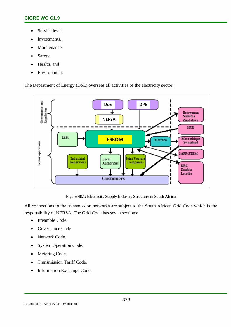
CIGRE WG C1.9
CIGRE C1.9 – AFRICA STUDY REPORT
373
Service level.
Investments.
Maintenance.
Safety.
Health, and
Environment.
The Department of Energy (DoE) oversees all activities of the electricity sector.
Figure 48.1: Electricity Supply Industry Structure in South Africa
All connections to the transmission networks are subject to the South African Grid Code which is the
responsibility of NERSA. The Grid Code has seven sections:
Preamble Code.
Governance Code.
Network Code.
System Operation Code.
Metering Code.
Transmission Tariff Code.
Information Exchange Code.

CIGRE WG C1.9
CIGRE C1.9 – AFRICA STUDY REPORT
374
Customers in South Africa are normally connected via Distribution Suppliers at distribution voltages
of less than 132 kV. These Distribution Retailers are either a municipality or in some areas, mainly the
rural parts of the country, an Eskom Distributor. These Distribution Suppliers or retailers are all
licensed by NERSA.
In some cases certain large power users are connected directly to the Transmission System depending
on the nature of the load and the connection. These are regarded and treated as special customers.
Generation is collected via an ‘Eskom Internal Pool’ from the various Eskom power stations and
international imports. This internal pool power is then sent via the Eskom Transmission system to the
different distributors across the country.
Certain of the municipalities have their own internal generation plant as well as small IPPs who are
connected directly to the Distributors.
Eskom has a separate fully owned subsidiary. Eskom Enterprises which manages projects within South
Africa as well as projects and utilities outside the borders of the country.
Figure 48.2: Existing Electricity Supply Structure in South Africa

CIGRE WG C1.9
CIGRE C1.9 – AFRICA STUDY REPORT
375
In order to facilitate this supply of power Eskom has been structured into three main core businesses,
namely
Generation Business
Networks and Customer Services Business
Corporate division
This is the structure as in 2010 with a number of subsidiaries which fall under a holdings company,
Eskom Holdings Limited, of which the Government is the only shareholder. This structure is shown in
figure 48.3.
However in order to face the challenges of the future where there will be more IPPs and a drive for
renewable energy Eskom will be restructured during 2011. The process is still at an early stage but
Eskom will be reorganized into a number of ‘Divisions’ and ‘Operating Units’ reporting directly to the
CEO. The final structure is not complete and is subject to change after consultation with key
stakeholders within Eskom, the Government and the industry. These are currently expected to be as
follows:
Core Divisions:
Generation
Transmission
Distribution
Customer Service
Support Operating Units:
Group Commercial
Human Resources
Finance
Technology
Other strategic Operating Units (list not complete):
Single Buyer Office
Southern Africa Energy
Renewables
Shared Services
Academy of Learning

CIGRE WG C1.9
CIGRE C1.9 – AFRICA STUDY REPORT
376
Figure 48.3: The Eskom Holdings Limited structure in 2010
48.2 Load and Energy Forecasting
South Africa's energy sector is critical to the economy, contributing about 15% to the country's gross
domestic product (GDP). Between 2002 and 2007 the average growth in real GDP was 5.1%, with a
GDP of R1 994bn in 2008.
In 2010 the peak demand was 35 850 MW with sales within South Africa of 205 365 GWh and
international sales of 13 227 GWh. Growth in sales was 1.7% from the previous year which had a
negatives growth of 4.2% triggered by the global recession. The number of customers supplied and
electricity sales for 2010 are shown in Table 48.1.
Long term energy growth in SA is primarily driven by increased industrial and residential
(electrification) load. Methodologies used for electricity demand forecast include:
Mixed end-use energy.
Bottom-up approach.

CIGRE WG C1.9
CIGRE C1.9 – AFRICA STUDY REPORT
377
Econometric regression analysis.
o A regression model depicts the effect of the economic growth (gross domestic product
growth), population growth, electrification and fuel switching, on the demand for
electricity.
A new method for determining the MW demand growth forecast has recently been developed, known
as the Balanced Base Line method which takes into account a number of independent sources of the
actual spatial economic growth and relates the demand to the various substation load points. The
forecasts are then compared against the projected S-curve of the future demand to arrive at the
balanced base line values. The graph in Figure 48.4 shows the historical demand growth from 1951 to
2009 and then the projected demand growth till 2051.
Figure 48.4: Historical and Project Demand Forecast for South Africa from 1951 to 2051
The expected peak demand for 2020 is around 54 000 MW and in 2030 around 62 000 MW. This takes
into account the changing load pattern where there is expected to be an increase in service orientated
business and a reduced growth in the primary resources business such as mining.
This demand growth represents a significant challenge to Eskom and the country as a whole in terms
of accessing and integrating the new generation. South Africa has an abundance of coal, but building
new coal fired plant is both getting more expensive and also becoming less acceptable globally in
terms of contribution to greenhouse gas pollution. Thus South Africa will have to consider increasing
nuclear and renewable energy options as there are no local natural gas resources. Renewables are very
new to South Africa, but there is an abundance of both wind and solar resources. However neither are

CIGRE WG C1.9
CIGRE C1.9 – AFRICA STUDY REPORT
378
close to the existing transmission infrastructure and load centres which will prove a challenge to
integrate them into the network.
Table 48.1: Sales of electricity and number of customers in South Africa
The reference plan is be based on the Balanced Base Line demand forecast and will represent the least
cost plan constrained to the established reserve margin.
A typical weekly load profile is shown in Figure 48.5 with two daily peaks.
The peak for each day occurs in the late afternoon or early evening.
Note the difference in generation between 02h00 and 12h00 each day.
The difference between the planned or forecasted load and the actual load requires the System
Operator to raise and lower the generation from 20 000 MW to 34 000 MW each day.

CIGRE WG C1.9
CIGRE C1.9 – AFRICA STUDY REPORT
379
Figure 48.5: Typical Weekly Load Profile in South Africa.
48.3 Planning and Design Criteria
Eskom has recently returned to a deterministic N-1 planning criterion which has now been included in
the 2008 version of the South African Grid Code.
Eskom still uses probabilistic measures of reliability such as loss of load probability (LOLP), loss of
load expectation (LOLE), and cost of un-served energy (CoUE) when justifying new projects.
However in the case of N-1 contingencies, the probability of the event is assumed to be 1 for
calculating the impact.
The Eskom transmission system operating and planning criteria are specified in the South African Grid
Code. The transmission planning standards specify an N-1 criterion for loads and N-2 criterion for
base load generating plant greater than 1000 MW subject to the loss of their smallest unit at the power
station. With regard to reserve margin, Eskom’s standard is to have a reserve margin greater than
15%. Due to a shortage of generating capacity, this reserve margin is not currently achieved and is
expected to be very constrained, dropping to below 5% until 2014.
Fundamentally the N-1 planning criterion is on a deterministic basis, but supported by probabilistic
planning. This means the network should remain stable after the loss of any single component.
However, in order for any transmission reinforcement to be approved, there is a requirement for

CIGRE WG C1.9
CIGRE C1.9 – AFRICA STUDY REPORT
380
Eskom to make a business case before such reinforcement can proceed. To make such a business case,
a new line must satisfy one of the following two economic criteria:
The net present value (NPV) of the cost of losses and operation and maintenance is greater than
the cost of the reinforcement; or
The expected NPV of the cost of interruptions to customers associated with unreliability must
exceed the cost of the reinforcement. Such costs are evaluated using the cost of un-served
energy.
The Least Economic Cost (LEC) method is used for planning the expansion of the grid. This method
looks at:
the probability of losing one, or more, network components, and
the impact this has on the transfer capability.
With regard to the planning studies the standards that are applied are provided in the following three
tables:
Table 48.1: Voltage Limits for planning purposes
Table 48.2: Standard Voltage Levels as used in South Africa
Table 48.3: Target Voltage levels for planning purposes
The system frequency limits for South Africa are provided in the graph in Figure 48.6.
Eskom has a Planning Guideline which details the necessary studies to be undertaken and what load
conditions to consider when undertaking the studies. The studies encompass steady state, fault current
and dynamic studies. Small signal analysis is done on the whole network to identify any potential
problems. The guideline also details how to evaluate different options and what criteria to apply when
selecting the recommended option to reinforce or extend the transmission network.

CIGRE WG C1.9
CIGRE C1.9 – AFRICA STUDY REPORT
381
Table 48.2: Voltage Limits for Planning Purposes
Table 48.3: Standard Voltage Levels as used in South Africa

CIGRE WG C1.9
CIGRE C1.9 – AFRICA STUDY REPORT
382
Table 48.4: Target Voltage for Planning Purposes
Minimum steady state voltage at bus supplying customer load. 0.95 UN
Minimum steady state voltage on any bus not supplying a customer.
System healthy:
After designed contingency:
0.95 UN
0.90 UN
Maximum harmonic voltage caused by customer at PCC.
Individual harmonic:
Total (square root of sum of squares):
0.01 UN
0.03 UN
Maximum negative sequence voltage caused by customer at PCC.
Continuous single-phase load connected phase-to-phase:
Multiple, continuously varying, single-phase loads:
0.01 UN
0.015 UN
Harmonic voltage limits.
As Defined in
NRS 048
Maximum voltage change owing to load varying N times per hour.
(4.5 LOG10N)% of
UN
Maximum voltage decrease for a 5% (MW) load increase at receiving
end of system (without adjustment).
0.05 UN
Figure 48.6: System Frequency Limits for South Africa
Nominal
(50 Hz)

CIGRE WG C1.9
CIGRE C1.9 – AFRICA STUDY REPORT
383
48.4 Planning Approaches and Methods
The Transmission Network is designed to supply the expected demand into the future while integrating
the expected new generation as specified in the national Integrated Resource Plan (IRP). The IRP
reflects the national energy plans for the country and is the responsibility of the Government though
the Department of Energy (DoE) which covers a period of up to 20 years.
The network is studied to determine what is required to meet the above country needs while still
meeting the criteria specified on the Grid Code. These planning studies are done in two phases which
are undertaken in parallel.
The first study is a Strategic Grid Plan (SGP) which considers the long term (20 – 30 year)
development of the transmission grid taking into account possible generation scenarios. This gives an
indication of the important strategic transmission decisions that need to be taken and when they need
to be taken in the form of decision trees. This study is undertaken every 3 years.
The second study is the 10 year Transmission Development Plan (TDP) which covers a 10 year
period as the name suggests. This is based on a set of known generation assumptions and indicates the
network reinforcements that are required to achieve Grid Code compliance for this generation. This
study is undertaken on an annual basis.
These two development plans are the responsibility of the Grid Planning department of Eskom.
From the 10 year TDP the actual Eskom Investment Plan for the transmission grid is prepared taken
into account resource constraints such as financial and construction capacity. The Investment Plan is
submitted to the regulator (NERSA) along with the tariff application for a three year period for
approval. After approval the plan can be implemented and all approved projects and any constraints
are fed back into the planning process to provide feedback for the next cycle.
This electricity planning process is represented at a high level in the flow chart in Figure 48.7.
The main Transmission Network in South Africa consists of 220 kV, 275 kV, 400 kV and 765 kV.
There is a single HVDC 533 kV interconnection with Mozambique, 1400 km long. A map if the main
network is given in Figure 48.8. A list of all the major equipment at both the transmission level and the
distribution level connected in 2010 is provided Table 48.6.
The list of major transmission equipment to be added to the network during the period 210 to 2019 as
per the TDP is given in Table 48.7. The new main transmission lines as per the TDP are marked in the
darker lines on the map in Figure 48.9.

CIGRE WG C1.9
CIGRE C1.9 – AFRICA STUDY REPORT
384
The relative locations of the Eskom power stations are shown in the map in Figure 48.10 with the
detailed list of the power station capacities given in Table 48.8.
Figure 48.7: South Africa Electricity Planning Process Flow Chart
Figure 48.8: Map of the major Transmission Network of South Africa as in 2009

CIGRE WG C1.9
CIGRE C1.9 – AFRICA STUDY REPORT
385
Table 48.5: Transmission and Distribution equipment in service in 2010
Table 48.6: New Transmission equipment to be added during the period from 2010 and 2019 as per the
Transmission Development Plan
TDP New Asset Total
HVDC Lines (km) 1,700
765kV Lines (km) 6,770
400kV Lines (km) 8,355
275kV Lines (km) 831
Transformers 250MVA+ 103
Transformers <250MVA 29
Total installed MVA 67,840
Capacitors 19
Total installed MVAr 2,366
Reactors 56
Total installed MVAr 14,600

CIGRE WG C1.9
CIGRE C1.9 – AFRICA STUDY REPORT
386
Figure 48.9: Map of the Transmission Development Plan for the period 2010 to 2019 showing the major
transmission projects
Existing Eskom Power Stations in 2009
G G
G G
2 409

CIGRE WG C1.9
CIGRE C1.9 – AFRICA STUDY REPORT
387
Figure 48.10: Map of the existing Eskom power stations in 2009
Table 48.7: Eskom Power Station Capacities in 2010
Three new Eskom power stations have been approved and are currently under construction. They are
as follows:

CIGRE WG C1.9
CIGRE C1.9 – AFRICA STUDY REPORT
388
Table 48.8: New power stations under construction
Name Type Size 1st
unit last unit
Medupi Coal fired 6 x 800 MW Dec 2012 Jun 2015
Kusile Coal fired 6 x 800 MW Dec 2014 Sep 2018
Ingula Pumped Storage 4 x 333 MW Jan 2014 Sep 2014
48.5 Specific Technical Issues
Integration of large amounts of renewable energy generation
The first major challenge for Eskom and the country is the integration of large amounts of renewable
energy (RE) generation into the national grid. The SA Government has committed to significantly
reducing the country’s emissions and reduce the dependence on coal by changing the generation mix
of the new future generation. One option will be the building of new nuclear power stations, but there
is a significant drive to introduce large scale RE generation.
South Africa has two resources in abundance, namely wind and solar. Both are in the less developed
part so the country where there is little infrastructure. Integrated and coordinated planning with the
other providers of infrastructure services will be required to successfully achieve this goal. While the
solar options are relatively predictable in their output and therefore can be planned for, the bigger
challenge will be the wind with its intermittent nature.
South Africa has implemented programme for CFL Exchanges, Power Alert on National TV, Solar
Water Heating, Energy Efficient motors, Residential Load Management, Load Management Pilot
Project.
There is a REFIT programme about to be launched for 1 025 MW of RE generation. To put this into
context Eskom has by the end of 2010 had applications for connection of wind farm developments
alone in excess of 12 000 MW. There is a proposal for the development of a 5 000 MW solar park that
has been presented to Government. It is therefore expected that in the next Integrated Resource Plan
(IRP) from the Department of Energy that their will be a significant amount allocated to RE generation
in addition to the first REFIT offering of 1 025 MW.
The integration of RE generation represents the biggest challenge to Eskom in terms of processing the
applications as well as developing long term plans to the best benefit of the country.
Recycling of transmission lines
Recycling of transmission lines to higher voltages is an important component of increasing some of the
power corridor transfer capacities as well as increasing the capacity of the internal Grid networks. In
some cases this means breaking down the lines and replacing them with new single or even double
CIGRE WG C1.9
CIGRE C1.9 – AFRICA STUDY REPORT
389
circuit lines. However some of the lines could be either re-conductored with a larger conductor bundle
or re-insulated to operate at a higher voltage. It is recommended that all the 275 kV lines and many of
the 400 kV lines be investigated to determine what potential uprating or upgrading is possible using
the existing tower structures.
Implementation of HVDC schemes
Results from the analysis of the generation power pools in the Strategic Grid Plan studies indicate that
there will be excess generation in either of the two extreme ends of the network, to the north and to the
south. The generation far exceeds the local or nearby loads and the excess power will have to be
transported over a long distances to where the power is required. The viable long term options are to
construct HVDC schemes to undertake this as they provide the significant operational advantage of
increased generation stability capability. It has been strongly recommended that Eskom undertake all
the necessary research activities to fully understand the construction and operation of conventional
HVDC schemes in preparation to construct and commission the first internal HVDC scheme by 2018.
Introduction of 500 kV as a new voltage level
It has been proposed that energising some of the Eskom 400 kV lines at 500 kV should be investigated.
Increasing the voltage from 400 kV to 500 kV provides a significant increase in transfer capacity for a
relatively little cost. While it is recognised that this is not a standard voltage level for Eskom and faces
difficulties at the substation level in terms of moving between the voltages, it is also be recognised that
it is a standard and well developed voltage level internationally. It is not suggested that an ambitious
scheme to upgrade the whole 400 kV network to 500 kV, but rather that certain areas could be targeted
to implement a gradual phasing in because of long term strategic advantages.
One significant advantage for introducing 500 kV in the northern part of the country is that it would
make the ideal voltage for establishing new interconnections with the neighbouring countries. The
500 kV voltage is more flexible and cost effective than the 765 kV as well as being very effective for
long distance power transfer. The 500 kV power transfer capacity would be more in line with the
gradual phasing in of the new generation in the region as opposed to make a huge step increase 765 kV
network that has significant operational challenges. The 500 kV network would make it easier for the
neighbouring countries to establish transmission step-down injections to develop their own internal
networks. This is a major political advantage to making these interconnections a reality.
International Interconnection opportunities for importing
There are many opportunities for international interconnections and Eskom needs to determine where
these potential imported power projects would provide the most benefit to the transmissions network.
The first opportunity is in the long term is for the neighbouring countries to reduce their forecasted
imports from Eskom with their own internal generation, thereby reducing the generation capacity

CIGRE WG C1.9
CIGRE C1.9 – AFRICA STUDY REPORT
390
demands within the Eskom network. The current forecast includes a significant component of exported
power, particularly to Mozambique, to meet the load growth target. However timing always plays the
major deciding factor in these projects and it is necessary to identify the best connection points within
the Eskom network for imported power projects depending on the timing of these projects. Not only
must the best connection point be identified, but what generation or transmission development within
Eskom can be deferred or avoided, thus providing the full cost avoided benefit of an imported power
project.
Design Issues
Eskom transmission plans show that more than 6000km of 400kV and 765kV transmission lines are
needed in next 7 years, and more than 20000 MVA of transformer capacity will be added in the same
period in order to cater for expansion and align the network to the grid code.
Extensive use of guyed towers will be adopted, both cross-rope chainette type towers and guyed-V
towers as shown in the diagrams below:
Figure 48.11: Crossrope Suspension for TX lines

CIGRE WG C1.9
CIGRE C1.9 – AFRICA STUDY REPORT
391
Figure 48.12: Guyed-V Suspension for TX lines
These line designs have resulted in significant capital cost savings for Eskom, as well as excellent
technical performance. The tower and conductor selection process considers the entire life cycle of the
line, and includes studies not on just line losses, but entire systyem losses as well. The practices have
been captured in an international reference book called the Eskom Power Series.
In terms of substation design Eskom is now also adopting the breaker and a half layout for some of the
new substations, to allow for higher reliability and easier maintenance outages.
Eskom has also commenced line and substation research and designs for the planned future HVDC
connections.
48.6 Financing Issues
The South African electricity infrastructure is funded by the tariffs which are approved by the
regulator, NERSA. All Eskom project approvals and funding are subject the Public Finance
management Act (PFMA) of South Africa as although no money is obtained directly from
Government, it is the sole shareholder in Eskom.
However, South Africa is facing a difficult time ahead to finance the huge build programme over the
next decade. The recent application for a 35% increase by Eskom over the three year period of 2010 to

CIGRE WG C1.9
CIGRE C1.9 – AFRICA STUDY REPORT
392
2012 to NERSA was rejected and an increase of only 25% allowed over the same period. This has
placed significant strain on the capital sources of Eskom and World Bank funding for part financing of
the two new large cola fired power stations was sought for the first time in Eskom’s history. The
Government has also had to provide guarantees for some of the funding for the first time. The reduced
tariff increase means that there will be large increases in the price of electricity over a longer period to
fund the capital expansion program.
Project development is required to meet one of the following investment criteria: before approval can
be given:
Least cost – e.g. new customers, reliability etc.
Cost reduction – e.g. capacitors.
Strategic – e.g. environmental, statutory, etc.
South Africa has created a successful model for collection of funds from energy exports which is based
on strict payment terms, guarantees and the involvement of a clearing bank.
48.7 Human Resources
As with all power utilities and the electricity industry there is a shortage of trained and skilled
engineering staff which Eskom has to address. Eskom places a lot of emphasis on training new
graduates and has a dedicated Academy of Learning division which coordinates and facilitates various
training programs. As a result there are a large number of young engineers in Eskom undergoing on
the job training and specialized training, but the numbers need to be increased to support the large buld
programme currently underway in Eskom.
With regard to planning staff there is a large planning department and a large system operations
department where all the network study work is undertaken in house by Eskom. Certain specific study
work is outsourced where the objective is to either have work verified or to gain experience in a new
field of study.
49. Sudan
49.1 Electricity Industry Structure
In 1982, the Sudan Government issued a decree which established the National Electricity Corporation
(NEC) as a statutory corporation under the Ministry of Energy and Mining, to be responsible for
electricity generation, transmission and distribution in Sudan.
In 1995, the total installed capacity on the national grid was increased to about 307.6 MW hydro-

CIGRE WG C1.9
CIGRE C1.9 – AFRICA STUDY REPORT
393
generation and 330.8 MW thermal generation. In addition to this, there are many thermal power
stations in isolated areas with a total capacity of 105.7 MW.
In 2001, the Electricity Act was issued, with its main objective being that the monopoly of the NEC
was eliminated, specifically in the electricity generation and distribution areas of the sector. In terms
of this Act, any private company or person has the right to generate and distribute electricity. The
Investment Act was also passed which has more attractive facilities to encourage foreign and local
investors in the sector.
The NEC is responsible for generation, transmission and distribution via the national grid and in
isolated areas of Sudan. It is a state-owned corporation under the Ministry of Energy and Mining and
owns and operates the country’s main generation, transmission and distribution assets. The electricity
system within Sudan is comprised of the main National Grid, a number of isolated off-grid systems
and some existing private generation companies.
Approximately 75% of the country’s total electric power is produced by the NEC. The remaining 25%
is generated for self-use by various industries including food processing and sugar factories, textile
mills, and the Port Sudan refinery [9].
The NEC grid system is a 220 kV national grid, transformed to 110 kV to the west, 110 kV and 66 kV
to the east and 500 kV to the north of Sudan. There are also fourteen isolated grids in the main towns
of the country.
Figure 49.1 below shows the layout of the transmission grid. Since 2002 the NEC, fully supported by
the Government of Sudan (GOS), has implemented a fast track programme which has successfully
added generation of 427 MW to the grids, national and isolated.

CIGRE WG C1.9
CIGRE C1.9 – AFRICA STUDY REPORT
394
Figure 49.1: National Grid of Sudan [3, 6]
The NEC manages installed electric generation capacity of just over 1 200 MW. [1]
There is no regulator for the electricity sector and there is little competition in this sector. There are a
few privately owned diesel-powered generators that provide electricity in regions outside the coverage
of the national grid [1].
In total it is estimated that only 30% of Sudan’s population has access to electricity [1, 2].
49.2 Load and Energy Forecasting
The economic factors that influence load and energy forecasts in Sudan are the following essential
economic parameters:
Gross domestic product (GDP) and
Industrial production.
The historical GDP growth rate is as shown in Table 49.1 below:

CIGRE WG C1.9
CIGRE C1.9 – AFRICA STUDY REPORT
395
Table 49.1: Historical Growth Rate (GDP)
Sector 1991–1995 1996–2000 2001–2005
1 – Agriculture
Irrigated crops
Rain fed mechanized crop
Rain fed traditional crop
Livestock
Forest, fishing & others
22.20%
12.60%
28.50%
51.90%
24.30%
12.50%
7.80%
7%
7.10%
7.70%
9%
4.20%
3.70%
6.70%
-9.90%
0%
4.70%
3.40%
2 – Industry
Mining quarrying
Oil
Manufacturing
Electricity & Water
Construction
4.70%
21.30%
10%
1%
6.20%
9.20%
15.50%
139.50%
255.20%
9%
3.70%
2.80%
13.50%
25%
26.30%
6%
2.20%
4.70%
3 – Commerce (services) 2.90% 2.40% 1%
4 – Government 1.80% -1.40% 24.90%
Total 9.70% 6.80% 7.20%
Electricity consumption refers to gross production, which includes consumption by station auxiliaries
and any losses in the transformers that are considered integral parts of the station. Also included is the
total electric energy produced by pumping installations without deduction of electric energy absorbed
by pumping [3, 4].
Table 49.2 shows electricity consumption from 1980 to 2002.
Table 49.2: Electricity Consumption [4]
Year 1980 1985 1990 1995 2000 2001 2002
Electricity consumption
(GWh)
876 1 295 1 327 1 421 2 451 2 560 2 897
The demand forecast for the domestic sector takes into account the following:
The extent of electrification is to be increased to 85% in 2030 from the present 18% in 2005.
The forecast of the number of households to be electrified every year is based on the population
projection and the estimated number of households.
The population census of 1993 was the basis for population & household projections.
The increase in specific consumption of electricity will primarily be dictated by changes in
average household income.

CIGRE WG C1.9
CIGRE C1.9 – AFRICA STUDY REPORT
396
Average energy consumption per household is assumed for each type of household.
The change in average household consumption could potentially be driven by changes in both
household income and price of fuels.
There is a small commercial sector in Sudan, and the following factors are taken into account in
forecasting its demand:
As with the domestic sector, the forecast of sales to the small commercial sector is a function of
the number of customers and specific consumption per customer.
Growth of the small commercial sector is expected to be closely linked to that of the domestic
sector.
The ratio of small commercial electricity customers to domestic electricity customers added to
the National Grid each year has remained fairly constant with an average of 170 new
commercial customers for every 1000 domestic customers connected to the national grid.
Future growth in small commercial customers is assumed to maintain this relationship.
The average electrical consumption of the small commercial sector is also likely to be driven by
average household income levels.
In the industrial and large commercial sector demand forecast, the following factors are taken into
account:
Future demand for electricity in this sector will again be a function of the numbers of
consumers and the average consumption per consumer.
The range, scale and diversity of services/products offered by this sector are such that the only
opportunity for drawing comparisons of consumption patters comes from firms producing the
same products.
Unlike the domestic sector, where it was identified that consumption increases with household
wealth and associated appliance ownership, consumption in the industrial sector is based upon
the electrical equipment designed and installed to achieve a targeted capacity of production.
Change in specific consumption of energy, including electricity, may be a function of
production, but once the maximum capacity is reached further consumption would be linked to
a change in operations or an expansion of the facilities.
With regard to the agricultural sector, it is estimated that the total agricultural land area of Sudan is 200
million feddans (1 feddan = 4 200 m2). Of this, the current area under cultivation does not exceed 40
million feddans which implies a utilization level of less than 20%. The electrical demand forecast for

CIGRE WG C1.9
CIGRE C1.9 – AFRICA STUDY REPORT
397
large scale irrigation schemes is therefore based upon the existing and forecast areas of land to be
irrigated by the different river systems, as stated in the Ministry of Irrigation’s Long-Term Agricultural
Strategy Plan for 2002 to 2027.
Table 49.3 shows the peak demand and the growth rate forecast, whilst Table 49.4 shows the
electricity consumption forecast. The results in Table 49.3 are graphically illustrated in Figure 49.2.
Table 49.3: Peak Demand Forecast (MW) & Growth Rate (%)
Case 2006 2010 2015 2020 2025 2030
High Case
Growth rate
1530 4731
33%
7199
9%
10191 7% 14023 7% 19184
6%
Base Case
Growth rate
1475 4550
33%
6693
8%
8995
6%
11205 4% 13883
4%
Low Case
Growth rate
1346 3987
31%
5513
7%
6800
4%
8086
4%
9808 4%
Table 49.4: Electricity Consumption Forecast (GWh)
Case 2006 2010 2015 2020 2025 2030
High Case 6559 23460 36574 53300 75695 103074
Base Case 6371 22820 34162 47007 60473 74569
Low Case 5589 19287 27899 35633 43993 53261
Figure 49.2: Peak Demand Forecast for Sudan to 2030

CIGRE WG C1.9
CIGRE C1.9 – AFRICA STUDY REPORT
398
49.3 Planning and Design Criteria
In 2004, Sudan had 760 MW of electricity generation capacity. Presently there are eight operational
stations, namely: Al-Damazeem, Al-Fashir, Al-Obayyed, Atbara, Dr Sharif Al-Hararivyah, Kasala,
Niyala and Qarri generation substation [5].
Sudan generated 3 800 GWh of electricity in 2004, and consumed 3 600 GWh. The majority of
electricity in Sudan is generated by conventional thermal sources (76%), with the remainder coming
from hydroelectricity (24%) as shown in Figure 49.3. The country’s main generating facility is the
280 MW Roseires dam located on the Blue Nile river basin [2, 6]. There are two projects for
generating additional capacity. They are Merowe and Kajbar hydroelectric facilities which will have
1 250 MW and 300 MW capacities respectively.
Figure 49.3: Sudan Electricity Generation by Source [2].
Table 49.5 shows the installed capacity for different energy sources [7]. Additional generation
capacity to be used to supplement the forecasted resources will be made available via the planned
interconnection between Sudan and Ethiopia which will be based on surplus firm and non-firm energy.
The proposed link is of double circuit 230 kV lines with a transfer capacity of about 200 MW. The
link starts from Bahir Dar substation passing through Gonder and Shehedi substations in Ethiopia and
ends at Gedaref substation in Sudan, with a total length of 296 km [7, 8].

CIGRE WG C1.9
CIGRE C1.9 – AFRICA STUDY REPORT
399
Table 49.5: Installed Generation Capacity – MW
Energy Source 2004
MW
2005
MW
2006
MW
2007
MW
HFO (Heavy Fuel Oil
(Petroleum)
649 649 649 649
Diesel 245 250 255 260
Hydro 308 308 308 308
Nuclear 0 0 0 0
Other 0 0 0 0
Total 1 201 1 206 1 211 1 216
The Generation Plan draws together all of the necessary inputs from the demand forecast report, the
hydrology data and the thermal generation data to derive the least cost generation plan for the NEC
Long-term Power System Planning Study (LTPSPS). The least cost generation plan and the associated
transmission plan is derived in economic terms to ensure that the projects selected make efficient use
of scarce national resources from the perspective of the economy.
The starting point for generation expansion planning is the demand forecast, which has been presented
and discussed in the Demand Forecast Report. The cost production simulations are based on the
manipulation of load duration curves representing the demand of the system. The basic shape of the
daily load curve may be entered either in the form of hourly load data or typical days over the year.
The annual forecast power and energy demands are also entered allowing for changes in the system
annual load factor.
Cost of production simulation, as discussed above, is done by using a programme that incorporates a
probabilistic production costing model. The model calculates the expected amount of energy
generated by each unit on the system together with the fuel and the operating and maintenance cost
associated with plant operation. Simulations may be carried out on an annual, seasonal or monthly
basis. The data requirements for simulation include:
Cost and operating assumptions for existing plant.
Technical and economic assumptions regarding the modeling methodology such as price basis,
time horizon, discount rate and security criteria (LOLP and ENS etc.).
Fuel price forecasts.
Cost and operating assumptions for potential new (candidate) plant.
The simulation process, which takes into account merit order dispatch and planned and forced outage
rates, is carried out as follows:
The dispatch of the composite hydroelectric plant is initially undertaken with a view to

CIGRE WG C1.9
CIGRE C1.9 – AFRICA STUDY REPORT
400
maximizing the use of total energy and available capacity.
The simulation is performed for each month, with plant on planned maintenance in that month
removed from consideration.
Planned maintenance is scheduled systematically into months with the highest monthly reserve
margins.
The lowest variable cost generating unit is dispatched first under the load duration curve for the
month. This determines its expected dispatch when it is available; its own forced outage rate is
factored in to determine its overall level of dispatch.
The second lowest cost unit is then dispatched. The dispatch of this unit is dependent on
whether the first is available, and to reflect this, an equivalent load duration curve (ELDC) is
derived to take account of the forced outage of the first unit. The second unit is then dispatched
under the ELDC, after which account of its own forced outage is made.
Subsequent units are dispatched following least cost merit order dispatch. Each time, a new
ELDC is derived which takes account of the forced outages of plant. The above process results
in the calculation of the amount of generation dispatched by each plant in each month. This is
summed to give annual totals.
The calculation is extended to determine total fuel costs O&M costs for the year. After all plant
has been dispatched, there will remain a small amount of demand which, in theory, cannot be
met. This is the energy not served (ENS) which is also calculated as part of the simulation
process along with the loss of load probability (LOLP).
The above simulation process is performed for different combinations of existing and new (candidate)
plant in different years as directed under the optimization process. For each combination, the key
results retained by the model are the annual values for total fuel and O&M costs, reserve margin, ENS
and LOLP.
Figure 49.4 shows the generation forecast and mix based on the forecast up to 2030:

CIGRE WG C1.9
CIGRE C1.9 – AFRICA STUDY REPORT
401
Figure 49.4: Generation Forecast and Generation Mix Based on Forecast to 2030
The transmission network is planned such that an outage of any component (e.g. overhead line,
transformer, etc) or any generating unit can be accommodated. It should be noted that there might be
some loss of supply in the event of multiple or overlapping outages. Transmission circuits are
generally reliable (provided they are adequately maintained) and an N-1 criterion is usually found to
provide acceptable reliability. The use of an N-1 security criterion is considered appropriate for
planning the transmission system of the Sudan. Thermal ratings of equipment should not be exceeded
during the outage of an item of plant and voltages should remain within limits.
Circuit ratings
The existing NEC transmission system uses 220 kV, 110 kV and 66 kV overhead transmission lines,
and in the future the Merowe hydro-electric power plant will be connected to the rest of the system via
500 kV transmission lines. The type, thermal rating and electrical parameters of these lines are used
for transmission system planning. The thermal rating is based on the following conditions: ambient
temperature 40°C, maximum conductor temperature 75°C, intensity of solar radiation 1200 w/m2,
wind velocity 1 mph.
Fault levels
Fault levels should remain within the capability of the plant. Fault levels will be calculated so that the
most onerous case is considered. In line with commonly adopted practice for networks and planning
studies of this type, three phase fault levels will be considered in this study.
Balance by using
interconnector

CIGRE WG C1.9
CIGRE C1.9 – AFRICA STUDY REPORT
402
Transient stability
Generation and generation groups should retain stability with the system for a three-phase fault which
is cleared within 120 ms. Stability should be retained post-fault with the faulted circuit no longer in
service. The network should not exhibit any poorly damped natural frequencies that could give rise to
sustained oscillations between machines or machine groups.
Power system studies
Load flow, fault level and transient stability studies are conducted with the objective of identifying the
required transmission system reinforcements to accommodate the forecast growth in levels of demand
and generation whilst meeting the planning criteria. The main emphasis is on load flow studies which
are used primarily to identify the transmission circuit and reactive power requirements. Fault level
studies are used to determine the prospective short circuit currents and thereby identify the switchgear
rating requirements. Transient stability studies are used to confirm that the generation on the system
will remain in synchronism following major, credible disturbances.
Power system planning model
NEC uses power system simulation software to test the system performance against the planning
criteria over the study period. The model incorporates the projected increase in demand derived from
the demand forecast and generation dispatch based on the least cost generation expansion plan. A
single element outage applies in turn to each circuit and transformer on the system.
Power factor
In the load flow studies, a load power factor of 0.85 is assumed for the 66 kV and 110 kV loads, and a
0.8 power factor for loads connected directly to 220 kV busbars. These power factors have been found
through measurement to be representative of conditions on the NEC system at these voltage levels. As
is the case here, it is usual to find lower overall power factors on higher voltage busbars. This is due
primarily to reactive power losses in the step down transformers.
49.4 Planning Approaches and Methods
Reliable provision of low-cost electricity is critical for industrial development, employment and
poverty alleviation. Shortages of electricity are also a severe constraint on economic growth. In some
of the Eastern Nile (EN) countries, lack of electricity is often exacerbated by shortages of imported
fuel, wood/charcoal and other forms of energy. One way to increase access to electricity is through
power trade and co-operative development of hydropower and transmission interconnection
investment projects. Significant opportunities for such projects exist in the EN countries. There is
substantial untapped hydropower potential in Ethiopia and Sudan. In view of transmission distances
and power markets, the power grids in Ethiopia and Sudan could be interconnected, enabling power

CIGRE WG C1.9
CIGRE C1.9 – AFRICA STUDY REPORT
403
trade between these two countries. Future interconnection of the grids in Ethiopia, Sudan, and Egypt is
also possible. Interconnection of the Ethiopia and Sudan power systems would thus enable improved
economics and increased reliability of supply in the two countries by taking advantage of the hydro
thermal complementarities of the power systems and some variability in peak demand. The two
countries would be able to trade not only energy but also reserve capacity, thus facilitating a reduction
in the total reserve margin on the interconnected system, as well as capital and operating costs. Other
benefits derived from the construction of the transmission line would include lower energy costs if
expensive diesel generated electricity is avoided [10].
This generation capacity to be used to supplement the forecasted resources will be made available via
the planned interconnection between Sudan and Ethiopia which will be based on surplus firm and non-
firm energy. The proposed link is a double circuit 230-kV line with a transfer capacity of about
200 MW. The link starts from Bahir Dar substation passing through Gonder and Shehedi substations
in Ethiopia and ends at Gedaref substation in Sudan with a total length of 296 km [7, 8].
The planned transmission expansions for the Sudan, based on the demand forecast and the generation
plan, is shown in Figure 47.5 below. A number of 110 kV, 220 kV, and 500 kV lines and associated
substations are anticipated as shown in the figure.

CIGRE WG C1.9
CIGRE C1.9 – AFRICA STUDY REPORT
404
Figure 49.5: Planned Sudan Transmission Network for year 2030
49.5 Specific Technical Issues
The country’s main hydroelectricity generating facility is the 280 MW Roseires dam located on the
Blue Nile river basin, approximately 315 miles southeast of Khartoum. The facility has frequently
been attacked by rebel groups, and low water levels often cause its available capacity to fall to 100
MW [6].

CIGRE WG C1.9
CIGRE C1.9 – AFRICA STUDY REPORT
405
Measures are being taken to ensure that existing hydro facilities are protected from the extreme climate
which causes silt build up, reducing their generation capacities [1].
Sudan’s main energy source is biomass, mostly in traditional uses. The national electricity grid
reaches a half million households, less than 10% of the population. Major and minor local grids serve
another 5%. At present there is no national interconnected grid covering the whole country.
In 2000, the Global Environment Facility (GEF) launched a project to create a sustainable technical,
institutional and financial infrastructure to support the market penetration of solar photovoltaic (PV)
systems. The project was aimed to meet the growing energy demand in semi-urban Sudan with PV,
rather than diesel systems. The project established a strong network of partnerships among the central
and state government, the Sudan Environment Conservation Society, the Energy Committee of the
National Assembly and the Energy Research Institute [11].
49.6 Financial Issues
Many new projects are sponsored by foreign governments as follows:
An agreement to finance the Kajbar project was signed between Sudan and China in September
1997. In terms of the agreement, China is financing 75% of the project (approximately US$200
million) and Sudan is to provide the remaining 25% [12].
In December 2003, the French power firm Alstom agreed to a US$300 million loan to construct
the dam for Merowe facility, while Harbin Power of China signed an agreement to build seven
sub-stations and around 1000 miles of transmission lines.
In 2002, the Merowe project received major funding commitments from Saudi Arabia, Qatar,
and other Arab states, with each having pledged loans of US$15 million or more. Two
consortia met the 2002 deadline to bid for the contract to build three packages of the civil works
portion of the dam, which has been estimated to cost about US$1 900 million [12].
The cost of introducing PV systems in the major social centers of 1 000 villages was
incorporated into the government’s developmental budget. However, for the later stages the
cost of systems in the social centers is expected to be covered through installment payments by
the users [11].
For the Ethiopia-Sudan interconnection the value of the consultancy contract is €1.5 million,
and it will be completed in 20 months. The financing of the Ethiopia-Sudan project is from the
World Bank [13].

CIGRE WG C1.9
CIGRE C1.9 – AFRICA STUDY REPORT
406
49.7 Human Resource Issues
The NEC manages the planning of generation, transmission and distribution of electricity. For the new
interconnection between Ethiopia and Sudan, Hifab Oy, together with its JV partner Fichtner from
Germany, will supervise the construction of the transmission lines and substation on the Ethiopian side
[13].
49.8 References
1. http://www.reeep.org/index.php?id=9353&text=policy-db&special=viewitem&cid=60
2. http://www.eia.doe.gov/cabs/Sudan/Electricity.html
3. http://www.iaea.org/inisnkm/nkm/aws/eedrb/data/SD-elex.html
4. http://globalis.gvu.unu.edu/indicator_detail.cfm?IndicatorID=46&Country=SD
5. http://www.zawya.com/cm/profile.cfm/cid852320
6. http://www.eoearth.org/article/Energy_profile_of_sudan
7. www.absenergyresearch.com
8. http://www.bgr.de/geotherm/ArGeoC1/pdf/06%20Energy%20master%20plan.pdf
9. Countries Worldbank
10. http://ensap.nilebasin.org/index.php?option=com_content&task=view&id=40&Itemid=76
11. www.theGEF.org
12. http://goliath.ecnext.com/coms2/gi_0199-3449054/SUDAN-Electricity.html
13. http://www.hifab.se/templates/NewsPage.aspx?id=590&epslanguage=EN

CIGRE WG C1.9
CIGRE C1.9 – AFRICA STUDY REPORT
407
50. Swaziland
50.1 Electricity Industry Structure
The Kingdom of Swaziland is located in south eastern Africa. It is a landlocked country bordered by
Mozambique to the east and the Republic of South Africa on all other sides. The Kingdom of
Swaziland covers an area of 17 360 km2. The country’s population is estimated at 1.2 million.
Swaziland’s power is supplied and distributed by the Swaziland Electricity Company (SEC). The SEC
is responsible to the Ministry of Works, Power and Communications. The Ministry of Natural
Resources and Energy is the national energy authority. The SEC currently has a monopoly on the
import, distribution and supply of electricity via the national power grid. The SEC owns the majority
of the country’s power stations. There are also five private power stations, including three sugar mills
and one pulp mill which burn biomass for generation, and a mine which burns coal.
In February 2000, the SEB joined the Southern African Power Pool as a full member. Swaziland is
able to freely purchase power whenever prices are reasonable within the Power Pool, without being
restricted to one supplier, as was the case previously.
A reform of the energy sector has been undertaken to reduce the monopoly of the utility (change from
a board to a company in 2007), establish a regulatory body and preserve the state company as a more
disciplined corporate entity [1].
Three regulatory bills have been approved by the Swaziland Parliament [1]:
the Swaziland Electricity Act of 2007,
the Swaziland Electricity Company Act of 2007, and
the Swaziland Regulatory Authority Act of 2007.
which enable the establishment of Independent Power Producers (IPPs) and introduce competition into
the electricity supply industry.
The Ministry of Natural Resources and Energy (MNRE) is the national energy regulatory authority.
The Energy Regulator was established by the Regulatory Authority Act of 2007 [1].
The powers and functions given to the Authority are to [1]:
receive and process applications for licenses,
modify/vary licenses,
approve tariffs, prices, charges and terms and conditions of operating a license, and
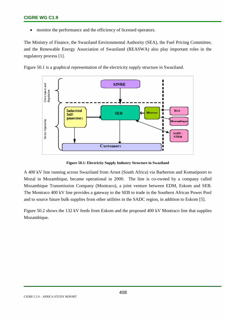
CIGRE WG C1.9
CIGRE C1.9 – AFRICA STUDY REPORT
408
monitor the performance and the efficiency of licensed operators.
The Ministry of Finance, the Swaziland Environmental Authority (SEA), the Fuel Pricing Committee,
and the Renewable Energy Association of Swaziland (REASWA) also play important roles in the
regulatory process [1].
Figure 50.1 is a graphical representation of the electricity supply structure in Swaziland.
Figure 50.1: Electricity Supply Industry Structure in Swaziland
A 400 kV line running across Swaziland from Arnot (South Africa) via Barberton and Komatipoort to
Mozal in Mozambique, became operational in 2000. The line is co-owned by a company called
Mozambique Transmission Company (Montraco), a joint venture between EDM, Eskom and SEB.
The Montraco 400 kV line provides a gateway to the SEB to trade in the Southern African Power Pool
and to source future bulk supplies from other utilities in the SADC region, in addition to Eskom [5].
Figure 50.2 shows the 132 kV feeds from Eskom and the proposed 400 kV Montraco line that supplies
Mozambique.

CIGRE WG C1.9
CIGRE C1.9 – AFRICA STUDY REPORT
409
Figure 50.2: Proposed SEB Transmission System [2]
50.2 Load and Energy Forecasting
Demand forecast methodologies include:
Historical trend based on electricity demand and natural population growth.
Sectoral analysis within each industry.
End use methods are also applied depending on customer needs.
Table 50.1 is a list of the different fuel types used in Swaziland, as well as the energy demand
projections until 2030.

CIGRE WG C1.9
CIGRE C1.9 – AFRICA STUDY REPORT
410
Table 50.1: Swaziland’s Energy Demand Projections by Fuel Type (Million Gigajoules) [11]
Fuel and energy requirements are met from the following main sources: (1994 Energy Balance
Swaziland) [3]:
Fuel wood, biomass waste and other renewable sources (56%),
Petroleum products (22%),
Coal (16%), and
Electricity (6%).
It is estimated that the industrial customers represent 47% of total users, followed by domestic users
23%, irrigation 18%, commercial 11% and the rest represents 1% [3].
There are approximately 42 000 electrified households as well as 70 large energy users with
approximately 10 industrial users [1].
It is estimated that 40% of urban areas and 4% of rural areas are electrified. The estimated overall
electrification rate is 27% [1].
While the consumption of energy is low by international standards, the country’s use of energy is
higher per capita than many regional neighbouring countries [1].
A major concern is the potential for significant tariff increases due to the dependence on imported
energy from the SADC region and the imminent shortages of power in the region [1].
Government has expressed its commitment to extend the grid to rural areas through a rural
electrification programme started in the year 2000 [1].
Figures 50.3, 50.4 and 50.5 below are graphical representations for electricity net generation,
consumption, and installed capacity respectively from 1980 to 2006.

CIGRE WG C1.9
CIGRE C1.9 – AFRICA STUDY REPORT
411
Figure 50.3: Electricity Net Generation [9]
Figure 50.4: Electricity Net Consumption [9]

CIGRE WG C1.9
CIGRE C1.9 – AFRICA STUDY REPORT
412
Figure 50.5: Electricity Installed Capacity [9]
50.3 Planning and Design Criteria
The planning and design of substations and electrical networks are influenced by the power supply
feeds from South Africa and Mozambique [1].
Generation
The SEC generation is hydro reliant, with hydro generation capacity as follows [4]:
Ezulwini power station: 2x10 MW = 20.0 MW
Maguga: 2x9.6 MW = 19.2 MW
Edwaleni power station: (4x2.5 MW) + 1x5 MW = 15.0 MW
Maguduza power station: 5.6 MW
Mbabane Hydro: 2 x 0.25 MW = 0.5 MW
Total hydro generation is therefore: 60.3 MW
Edwaleni power station comprises three sets of diesel generation facilities. These however are seldom
utilized because of the high costs involved. Their generation capacity is:
Diesel stations: (2x4.5 MW) + 1 x 0.5 MW = 9.5 MW [4].

CIGRE WG C1.9
CIGRE C1.9 – AFRICA STUDY REPORT
413
Total diesel generation is therefore 9.5 MW.
Total installed capacity is thus 69.8 MW [4].
Electricity generation was self-sufficient until 1973 when a power shortfall was experienced due to the
growing demand, hence the first 132 kV Eskom line was built. Two additional Eskom feeders were
subsequently installed due to a further demand growth.
A 400 kV power line from Maputo was also introduced. This led to the establishment of a 400/132 kV
bulk supply substation at Edwaleni. The scope of the project also entailed the establishment of an
interconnected 132 kV grid which links to the existing three 132 kV Eskom lines.
Discussions are on-going regarding the possibility of constructing a thermal power station at Mpaka
where 1000 MW is expected to be generated on completion of the project [5]. Once completed, this
thermal power station will enable Swaziland to be self-sufficient, and excess power would be exported
to the rest of the SADC region.
Swaziland has been involved in a joint venture project with South Africa. The Swaziland Komati
Project Enterprise is a power project that is located in the Komati River Basin, and it entails
construction of two dams within Swaziland and South Africa for the purpose of hydroelectric power
generation and establishing agricultural projects.
Other major projects underway include the construction of power stations at Maguga Dam, a Systems
Losses Scheme aimed at reducing power losses and a feasibility study on the Bagasse Power Station,
which will reduce the country’s imports from South Africa [5].
Transmission & Distribution
The planning and design criteria adopted for the reinforcement and upgrade of the 132 kV network is
for firm or single contingency (N-1) capability for both transmission lines and substation equipment
[4].
50.4 Planning Approaches and Methods
The National Development Strategy (NDS) Unit is the main overall planning department. The NDS
consolidates all programmes aimed at achieving the National Vision [1].
The work of the NDS Unit brings together policy, strategic planning, the capital programme and the
budget, and requires regular liaison and communication with all players in the economy [1].
The Ministry of Natural Resources and Energy is responsible for overall energy policy planning [1].
CIGRE WG C1.9
CIGRE C1.9 – AFRICA STUDY REPORT
414
50.5 Specific Technical Issues
There is a huge mismatch between peak demand and generation, which results in an over-reliance on
imports.
The Swaziland Electricity Board is at a risk of losing some of its supply capacity due to the power
shortage issues within Eskom. Load shedding has been implemented during the peak demand season
to maintain network stability.
Access to electricity is very low.
Industry restructured in an attempt to encourage Independent Power Producers (IPPs). IPPs were
expected to increase after the enactment of the Electricity Act of 2007, however this has not been the
case.
The main identified barriers towards sustainable energy include [1]:
Mobilising funding for investment,
The size of the local energy market is very small,
Limited natural resources,
Diminishing power capacity in the Southern African region,
Swaziland imports the bulk of its commercial energy from neighbouring countries,
The high cost of renewable energy technologies, and
Insufficient investment flows.
Environmental issues related to the energy sector [3]:
Deforestation with regard to fuel-wood collection, bush clearing for electricity installations
using heavy equipment,
Pollution of air by burning of fuel-wood and coal,
Visual impacts; construction of power lines and destruction of trees, and
Human health and safety; respiratory ailments due to smoke and particulate matter from burners
and fire places and danger to human life by misuse of electricity.
50.6 Financing Issues
As with most Southern African countries, international donors and funders have an essential role for
the infrastructural development related to the energy sector [1].

CIGRE WG C1.9
CIGRE C1.9 – AFRICA STUDY REPORT
415
The Swaziland Electricity Board finances its operations and capital expenditure from company
generated revenue, government funding, donor funds, and bank loans.
Such donors include: the World Bank, United Nations Agencies, and individual countries [1].
For example, funding for the construction of Maguga Hydro Power Station was sourced as follows [6]:
€7.0 million from the European Investment Bank,
€11.2 million from the Government of Swaziland,
€41.0 million from Swaziland Electricity Board’s own resources,
€87.0 million from the Standard Bank Swaziland, and
The Rural Electrification Project was funded by the Chinese Government
50.7 Human Resource Issues
Energy policy and planning in Swaziland is controlled by the government via the Ministry of Natural
Resources and Energy (MNRE) [1].
The MNRE provides services in respect of, surveying, mapping and valuation of energy resources [4].
The MNRE is also in charge of planning and development [4].
The Government has plans to expand the rural electrification network and has stated clearly that rural
electrification will continue to be a priority and the efforts are led by the state [1].
50.8 References
1. Renewable Energy & Energy Efficiency Partnership (REEP). ‘Swaziland Policy and
Regulatory Review 2009’. URL http://reeep-sa.org/projects/doc_download/55-swaziland-
2009. Last accessed: 22 July 2009.
2. Global Energy Network Institute. ‘Map of Swaziland Electricity Grid’. URL
http://www.geni.org/globalenergy/library/national_energy_grid/swaziland/swazilandnationa
lelectricitygrid.shtml. Last accessed: 22 July 2009.
3. Swaziland Environment Authority. ‘The Swaziland Environment Action Plan (SEAP)’.
URL http://www.environment.gov.sz/files/seap.pdf. Last accessed 27 July 2009.
4. [Swaziland Electricity Company. URL http://www.sec.co.sz. Last accessed 27 July 2009.
5. Southern African Chamber of Commerce. ‘Swaziland – The Official SADC Trade, Industry
and Investment Review 2006’.
CIGRE WG C1.9
CIGRE C1.9 – AFRICA STUDY REPORT
416
URL http://www.sanec.org/images/stories/Country/Swaziland_Review_2006.pdf. Last
accessed: 27 July 2009.
6. Swaziland Electricity Board. ‘Consolidated Financial Statements for the Year Ended 31
March 2006’. URL http://www.seb.co.sz/images/SEB%20Part%20B.pdf. Last accessed:
23 July 2009.
7. Swaziland Business Yearbook 2009. ‘Employment’.
http://www.swazibusiness.com/sbyb2007/employment.html. Last accessed 24 July 2009.
8. European Union Energy Initiative. ‘Newsletter No. 1’. Last accessed 24 July 2009.
9. Energy Information Administration. ‘Swaziland Energy Profile’.
URL: http://tonto.eia.doe.gov/country/country_energy_data.cfm?fips=WZ
10. The Southern African Community Today. ‘2007 the year for energy security’.
URL: http://www.sardc.net/Editorial/sadctoday/view.asp?pubno=v9n6&vol=514
11. T.M. Mhlangeni. ‘Swaziland’s first national communication to the united nations
framework convention on climate change’.
URL http://unfccc.int/resource/docs/natc/swanc1.pdf. Last accessed: 28 July 2009.

CIGRE WG C1.9
CIGRE C1.9 – AFRICA STUDY REPORT
417
51. Tanzania
51.1 Electricity Industry Structure
Tanzania is located in East Africa with a population of 38.4 million, and covers area of 954 000 km2.
Tanzania has an estimated 3 800 MW of economic hydro potential capacity.
Primary energy consumption is 90.5% biomass, 8% petroleum products and 1.5% hydropower and
coal. About 11% of the urban population has access to electricity, and less than 2% of the rural
population. Most rural energy requirements are supplied by wood and charcoal. The government is
encouraging investment to expand generating capacity and the distribution system, and to develop
indigenous sources of energy.
Tanzania Electric Supply Corporation (TANESCO) is a vertically integrated utility responsible for the
generation, transmission, distribution and marketing of electricity in mainland Tanzania. TANESCO
also sells bulk power at 132 kV to Zanzibar Island. Electricity supply in Zanzibar is the sole
responsibility of the Zanzibar State Fuel and Power Corporation (ZSFPC), a vertically integrated
monopoly company.
Several IPPs are connected to the TANESCO grid, and imported power from Uganda and Zambia is
also connected to this grid.
The Ministry of Energy and Minerals approves tariff increases and regulates the industry, approves
power purchase agreements and issues licenses to IPPs. Energy and Water Utilities Regulatory
Authority (EWURA), regulates the sector.
Independent Power Tanzania Limited (IPTL) and Songas Limited are IPPs with off-take contracts with
TANESCO.
In August 1997, TANESCO was declared a specified public corporation. In line with the sector
objectives, the Government decided in principle that TANESCO would be privatized. In October 1999
the Government decided to restructure the energy sector in preparation for the privatization of
TANESCO, through the Presidential Parastatal Sector Reform Commission (PSRC).
Positive news update:
Tanzania has projects underway to increase access from 10% to 19% by 2013, by simplifying
processes and attracting investment into small renewable power projects.

CIGRE WG C1.9
CIGRE C1.9 – AFRICA STUDY REPORT
418
Figure 51.1: Electricity Supply Industry Structure in Tanzania
51.2 Load and Energy Forecasting
Tanzania’s energy demand and end-use structures can be categorized into:
Non-commercial,
Primary energy sources (mainly biomass fuels), and
Commercial energy (petroleum, natural gas, hydroelectricity, coal and geothermal energy).
The load forecast model uses a regression analysis with electricity sales, tariff levels, generation,
system losses and GDP as exogenous variables. The low and high scenarios then take into account not
only the economic and customer growth factors but also industrial development and the mining
industry.
Table 51.1: Tanzania Load Forecast Model
Source SSEA II – Regional Power Needs Assessment report

CIGRE WG C1.9
CIGRE C1.9 – AFRICA STUDY REPORT
419
Table 51.2: Tanzania Forecast Summary
Source SSEA II – Regional Power Needs Assessment report
Figure 51.2: Demand Forecast in Tanzania
Source SSEA II – Regional Power Needs Assessment report

CIGRE WG C1.9
CIGRE C1.9 – AFRICA STUDY REPORT
420
Figure 51.3: Energy Forecast in Tanzania
Source SSEA II – Regional Power Needs Assessment report
51.3 Planning and Design Criteria
TANESCO’s generation system consists of hydro, thermal and gas. Hydro contributes about 65% of
TANESCO’s power generation.
The existing TANESCO system consists of an interconnected system and several isolated systems with
total capacity of 839 MW. The peak demand is 654 MW.
51.4 Planning Approaches and Methods
TANESCO plans to reduce the country’s reliance on hydropower and imported petroleum, to increase
the population’s access to electricity, and general improvements of power supply availability and
quality.
The company plans to build new gas-fired power plants, substitute natural gas for diesel in other
plants, build new coal-fired power plants, and to develop geothermal and other renewable energy
sources.

CIGRE WG C1.9
CIGRE C1.9 – AFRICA STUDY REPORT
421
Table 51.3: Current and Future Generation and Transmission Projects.
Generation Additions MW Year Transmission Line kV km Year
Keycrezi CT 60 2005 Shinyange Mwanza 220 139 2010
Zambia Interconnector 200 2006 Ruhadji-mufindi-kihansi 220 200 2012
Ruhadji Hydro Power 358 2010 Ruhadji kihansi 220 200 2012
Conversion of oil fired CT - 2016 Kidatu-Morogoro-Ubango 220 310 2012
Mchuchuma caol fired plant 200 2013 Mchuchuma-Mufindi 220 283 2018
Mchuchuma caol fired plant 200 2020 Rumakali-Mbeya 220 85 2022
Rumakali Hydro 222 2023 Rumakali Mufindi 220 134 2022
Combustion Turbine 60 2026 Mchuchuma-Mufindi 220 283 2026
Tanzania has been carrying out the Power Master Plan (PMP) programme which has been updated
annually since 1980. The objective of the PMP is to determine the least-cost programme for the
development of Tanzania’s generation and transmission expansion plans, and to enable TANESCO to
understand the existing and future demand requirements for supply to the customer.
To improve power development in the country, TANESCO co-operates with the following
organizations and countries:
Southern African Power Pool (SAPP). The SAPP projects include:
o Zambia-Tanzania-Kenya interconnection,
o Malawi-Mozambique interconnection, and
o DRC-Zambia interconnection.
Most SAPP utilities recorded a positive demand growth of about 3%, attributed to positive economic
growth in most member countries:
Nile Basin Regional Power Trade Project. The NBI project objectives are:
o The establishment of an institutional means to co-ordinate the development of regional
power markets among the Nile Basin countries,
o To build analytical capacity and provide technical infrastructure, and
o To manage the development of the Nile Basin resources through equitable utilization of,
and benefit from, the common Nile Basin water resources.
Nile Equatorial Lakes Subsidiary Action Program (NELSAP). The NELSAP aims are:
o Developing infrastructure consisting of small scale hydropower developments in critical
areas, and
o Strengthening transmission interconnections between several countries in the NELSAP
region (Burundi, DRC, Kenya, Rwanda, Tanzania and Uganda).

CIGRE WG C1.9
CIGRE C1.9 – AFRICA STUDY REPORT
422
East African Regional Power Plan. The plan objectives are:
o East Africa, as a region, possesses adequate energy resources for the development of the
region. Under the auspices of the East African Community, the East African Power
Master Plan Study is being carried out to define the least cost expansion programme for
the development of combined power generation systems for Kenya, Uganda and
Tanzania.
51.5 Specific Technical Issues
Over the last period the East African region has been stricken by droughts, which have had great
adverse effects on Tanzania’s power supply. The lack of water in the hydro dams have led to
blackouts and power rationing in this region. As a result of this, Tanesco is now forced to utilize gas
powered generation and they also have to look at thermal alternatives for future expansion.
51.6 Financing Issues
According to the United States Energy Information Administration, in July 1999, Tanzania announced
attractive financial terms for potential investors in developing its vast renewable energy resources. It
has simplified procedures for investing in solar, wind and micro-hydro projects including a 100%
depreciation allowance in the first year of operation, exemption from excise duty and sales tax and
concessionary customs duty on the first import of materials used in renewable energy projects. In
addition extensive guarantees are provided to investors under the investment promotion centres
certificate of approval. Guarantees such are ownership of properties, dispensation of assets and
repatriation of income. Tanzania is also a member of multilateral arbitration agencies in case of
disputes concerning investors, notably the World Bank’s Multilateral Investment Guarantee Agency
(MIGA) and the international Centre for Settlement of Investment Disputes (ICSID) [1].
A report stated that the Tanzania Electricity Supply Company (Tanesco) needs USD 1.6 billion in
order to rehabilitate its infrastructure and enhance the Tanzania power sector by enhancing the overall
supply of its resources. Some of the contributors to the project, such as TEDAP, MCC, ADB, JICA
and South Korea, had already approved a total of USD 285 million to designate to this project, but
much more will be needed to keep up with Tanzania’s, already inflated, demand [2].
51.7 Human Resources
Governments and Non-Governmental Organizations (NGO’s) are approached to support the
implementation of a National Solar Programme in cohorts with the World Solar Programme (WSP).
Two of the five proposed projects that were submitted have been prioritised with utmost national

CIGRE WG C1.9
CIGRE C1.9 – AFRICA STUDY REPORT
423
importance. The solar electrification project is on village level and is dependent on donor support for
funding. No donor funds have been committed yet.
51.8 References
1. www.areed.org/country/tanzania/energy.pdf
2. www.tanzaniainvest.com/tanzania-energy-and-mining/news/285-tanzania-electricity-
supply-company-seeks-project-funding-
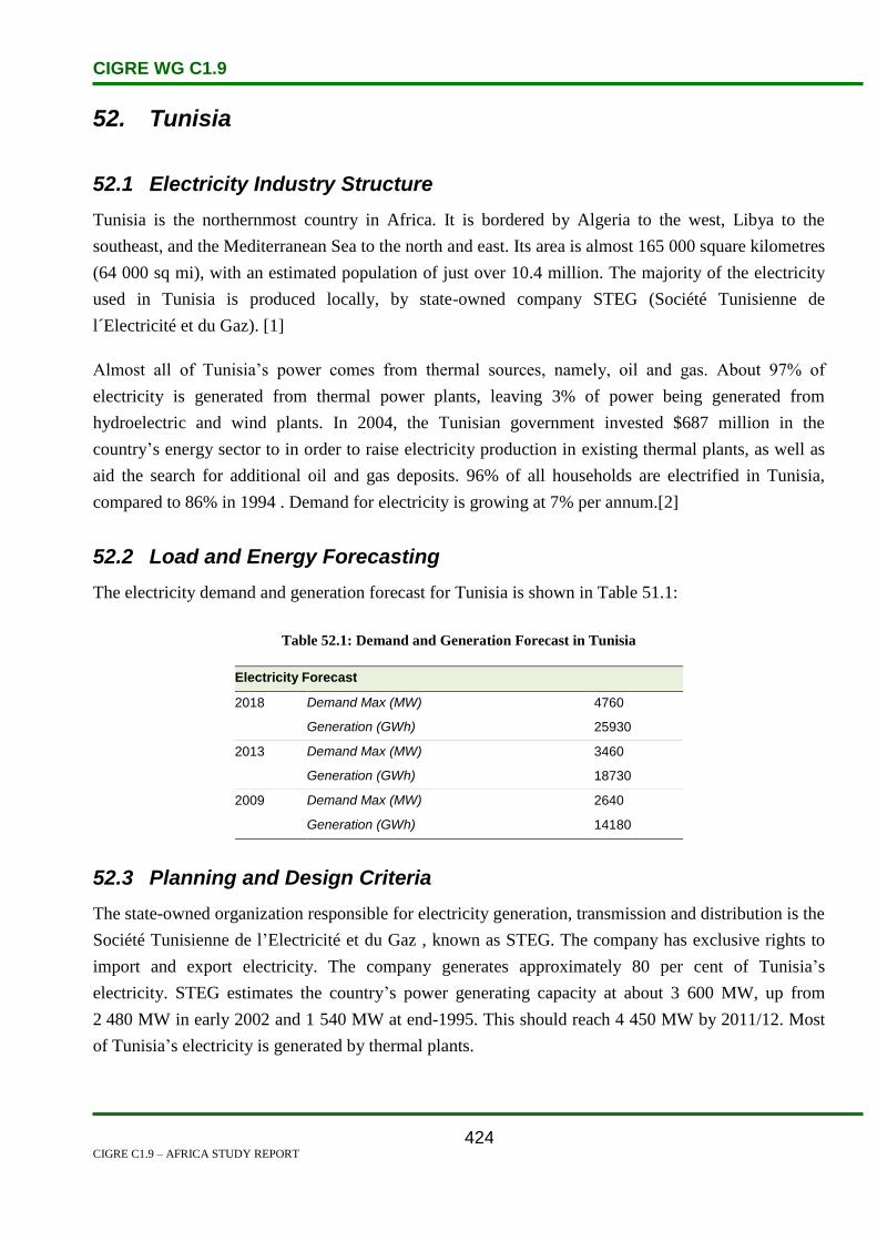
CIGRE WG C1.9
CIGRE C1.9 – AFRICA STUDY REPORT
424
52. Tunisia
52.1 Electricity Industry Structure
Tunisia is the northernmost country in Africa. It is bordered by Algeria to the west, Libya to the
southeast, and the Mediterranean Sea to the north and east. Its area is almost 165 000 square kilometres
(64 000 sq mi), with an estimated population of just over 10.4 million. The majority of the electricity
used in Tunisia is produced locally, by state-owned company STEG (Société Tunisienne de
l´Electricité et du Gaz). [1]
Almost all of Tunisia’s power comes from thermal sources, namely, oil and gas. About 97% of
electricity is generated from thermal power plants, leaving 3% of power being generated from
hydroelectric and wind plants. In 2004, the Tunisian government invested $687 million in the
country’s energy sector to in order to raise electricity production in existing thermal plants, as well as
aid the search for additional oil and gas deposits. 96% of all households are electrified in Tunisia,
compared to 86% in 1994 . Demand for electricity is growing at 7% per annum.[2]
52.2 Load and Energy Forecasting
The electricity demand and generation forecast for Tunisia is shown in Table 51.1:
Table 52.1: Demand and Generation Forecast in Tunisia
Electricity Forecast
2018 Demand Max (MW) 4760
Generation (GWh) 25930
2013 Demand Max (MW) 3460
Generation (GWh) 18730
2009 Demand Max (MW) 2640
Generation (GWh) 14180
52.3 Planning and Design Criteria
The state-owned organization responsible for electricity generation, transmission and distribution is the
Société Tunisienne de l’Electricité et du Gaz , known as STEG. The company has exclusive rights to
import and export electricity. The company generates approximately 80 per cent of Tunisia’s
electricity. STEG estimates the country’s power generating capacity at about 3 600 MW, up from
2 480 MW in early 2002 and 1 540 MW at end-1995. This should reach 4 450 MW by 2011/12. Most
of Tunisia’s electricity is generated by thermal plants.

CIGRE WG C1.9
CIGRE C1.9 – AFRICA STUDY REPORT
425
Tunisia has formed part of the trans-Maghreb electricity integration plan. The plan consists of the
trans-Maghreb project, and its purpose is to link the power grids of all the Maghreb countries to those
of Spain and the rest of the European Union. Tunisia, however, faces the challenge of having its
domestic power grid upgraded first so that domestic demand can be met and greater reliability can be
set in place. Tunisia already is linked to Algeria’s electrical grid, and efforts for the country to link its
grid to Libya’s grid have commenced. The connection of Libya and Tunisia’s networks are will allow
for an integrated North African power grid that will extend from Morocco to Egypt.[2]
Tunisia has plans for two nuclear power stations, to be operational by 2019. Both facilities are
projected to produce 900–1000 MW. France is set to become an important partner in Tunisia’s nuclear
power plans, having signed an agreement, along with other partners, to deliver training and
technology. [1]
52.4 Planning Approaches and Methods
The main technical criterion for transmission system development is the N-1 security criterion. It is
mostly related to the loss of single circuit, transformer or generator, when the following consequences
are to be avoided after the occurrence of a fault event:
thermal overloading of branches,
voltage deviations above permitted range,
loss of stability,
loss of load,
interruption of power transits, and
disturbance spreading over power system.
The N-2 criterion is not applied.
With regard to the security margins, some restrictions are imposed on the generating unit capability
limits, specifically on the Qmax and Qmin limits.
With regard to the capability of lines and transformers, the operational planning units in the national
dispatching centres usually do not define different thermal ratings for winter and summer operational
conditions, as happens in Europe, but rather for normal and emergency conditions. Moreover,
different ratings are defined based on the age of equipment.
For reliability analysis, probabilistic approaches or the assessment of the probability of N-1 events
during transmission system planning, are not considered. Methods used by transmission planners are
based on the deterministic approach, and the probabilities of the occurrence of the various events
(network failures, generator dispatch, branches availability, etc.) are not tak en into consideration.
CIGRE WG C1.9
CIGRE C1.9 – AFRICA STUDY REPORT
426
Such approaches can be found only in some studies performed by foreign consulting companies.
The North African power utilities do not have any specific construction criteria for interconnection
lines, but commissioning of an interconnection requires a higher hierarchical level of analysis where
possible incoherency in planning criteria and system constraints are solved, as well as all aspects
related to the engineering issues and co-ordination (e.g.: protection philosophy and relay settings).
Considering the complexity of interconnection studies, the pre-feasibility and feasibility studies for the
different kinds of interconnections (HVAC, HVDC) are frequently performed by foreign consulting
companies. The specific economic criteria for interconnection lines are based on difference in
electricity prices or on the overall change in system operational costs derived by different
interconnection options and different operating regimes of power systems.
The basic assumptions related to the N criterion of the transmission network are:
The rating limits of transmission lines should be regarded as maximum permanent currents.
In normal operating conditions, no overload of the transmission network is allowed.
No generator will be above its continuous reactive capability with possible restrictions decided
by the planner to account for operational constraints.
The loads are represented as constant active and reactive powers.
In normal operating conditions a long-term overload of transformers up to 10% of nominal
rating is allowed. A short term overload (less than 15 minutes) is allowed up to 20%.
For the transmission system generally, unless otherwise specified, the maximum operating voltages are
as follows:
For 400 kV network maximum voltage is 428 kV.
For 220 kV network maximum voltage is 235.4 kV.
For 150 kV network maximum voltage is 160.5 kV.
For 132 kV network maximum voltage is 141.2 kV.
For 90 kV network maximum voltage is 96.3 kV.
For 66 kV network maximum voltage is 70.6 kV.
The minimum operating voltages values are as follows:
For 400 kV network minimum voltage is 372 kV.
For 220 kV network minimum voltage is 204.6 kV.
For 150 kV network minimum voltage is 139.5 kV.
For 132 kV network minimum voltage is 122.8 kV.
For 90 kV network minimum voltage is 83.7 kV.

CIGRE WG C1.9
CIGRE C1.9 – AFRICA STUDY REPORT
427
For 66 kV network minimum voltage is 61.4 kV.
Operating Frequency:
The nominal frequency is 50 Hz and its permissible variation range under AGC is 50 ± 0.05 Hz.
Under normal operating conditions the maximum permissible variation range is50 ± 0.2 Hz.
N-1 Security Conditions.
The following criteria are applied under N-1 contingency conditions:
The transmission system should be planned such that reasonable and foreseeable contingencies
do not result in the loss or unintentional separation of a major portion of the network or in the
separation from the regional interconnected system.
During contingency conditions, a temporary overload of the transmission lines is allowed up to
20%.
A temporary overload of transformers is allowed in emergency conditions up to 20% during
peak hours.
The maximum post-transient voltage deviation is 10%.
For transmission system generally, unless otherwise specified, the maximum operating voltage values
are as follows:
For 400 kV network maximum voltage is 440 kV.
For 220 kV network maximum voltage is 242 kV.
For 132 kV network maximum voltage is 145.2 kV.
For 66 kV network maximum voltage is 72.6 kV.
The minimum operating voltage values are as follows:
For 400 kV network minimum voltage is 360 kV.
For 220 kV network minimum voltage is 198 kV.
For 132 kV network minimum voltage is 118.8 kV.
For 66 kV network minimum voltage is 59.4 kV.

CIGRE WG C1.9
CIGRE C1.9 – AFRICA STUDY REPORT
428
Operating range frequency:
During N-1 contingency conditions, the maximum and minimum permissible frequencies are
50.4 Hz and 49.6 Hz respectively.
In the case of a severe incident, the maximum and minimum permissible frequency limits are
52 Hz and 47.5 Hz respectively.
Transmission Network Planning Probabilistic Approach.
The probabilistic approach is seldom used in planning studies directly by the concerned transmission
system operators (TSOs) or vertically integrated undertakings (VIUs). However, the probabilistic
approach is being widely used in interconnection studies among the North African Countries (e.g., the
MEDRING and the ELTAM studies).
Unless specific data is provided, the basic assumptions adopted concerning the unavailability of the
transmission system, are given in the following table:
Table 52.2: Transmission Line Forced Unavailability Rate
Voltage Level
[kV]
Unavailability Rate
[p.u./100 km]
500–400 0.005
220 0.0025
150–90 0.005
As no reliability data on the transformers is available, standard hypotheses for these values are
assumed. It is assumed that the transformers have an availability of 99.5%.
Also, records on the reliability of reactors and capacitors are generally not available, hence standard
hypotheses for these values are adopted. More specifically, it is assumed that the reactive
compensation equipment has an availability of 99.5%.
Three different weather conditions, Normal, Bad and Stormy, are considered and, unless otherwise
specified, the parameters used to simulate the weather effects are set out in Table 52.3:
Table 52.3: Parameters of Weather Model
Weather Conditions Hours Ratio
[p.u.]
Coefficients
[p.u.]
Normal 0.9667 1.0
Bad 0.03 10.0
Stormy 0.003 15.0

CIGRE WG C1.9
CIGRE C1.9 – AFRICA STUDY REPORT
429
As an indicator of the system adequacy, the annual value of Expected Energy Not Supplied (EENS)
due to unavailability in the transmission system and/or generation considering the constraints
represented by the transport capacities of the lines and active power limits of the power plants is used.
A threshold value 10-4 p.u. is assumed for the EENS index related to insufficiency of the transmission
system due to a reduction in the transmission capacity of the network.
Economic evaluation in transmission-generation planning.
The price of EENS for an economic evaluation can vary from 0.5USD/kWh up to 2USD/kWh.
The generation margins and the loss of load probability adopted for the reliability study are the
following:
Minimum generation margin reserve: 15%.
Loss of load probability (LOLP): 5–24 hrs/year. The highest value is valid whenever the
systems are operated in islanded mode.
Power reserve requirements and criteria
Power systems in North Africa are operated with a primary frequency control and a LFC (Load
Frequency Control). Primary and Secondary reserves are determined by the operator.
The frequency and active power control is provided by the following means:
Automatic response from generating units operating in a free governor frequency sensitive
mode (Primary Reserve).
Automatic Generation Control (AGC) of generating units equipped with automatic load
frequency control (Secondary Reserve).
52.5 Specific Technical Issues
In March 2004, BG signed a Memorandum of Understanding (MoU) to construct a $250-million, 500-
MW power plant, known as the Barca power plant, near Sfax. This project has been under discussion
since December 2005. BG also plans to build a Liquefied Petroleum Gas (LPG) plant that will serve
the country’s energy market.
The government also plans to construct a wind-powered plant at the coastal city of Qalibeya. A rural
electrification programme is presently being implemented. This programme will add a further
2 000 km of distribution line to electrical power sector of the country.
A programme is currently being developed whereby nine small plants, with a total capacity of about
10 MW (60 GWh/year) will be constructed. There are small hydro plants being planned and these

CIGRE WG C1.9
CIGRE C1.9 – AFRICA STUDY REPORT
430
include: Barbara (3 MW), Sidi Saad (1750 kW), Siliana (850 kW), Bejaoua (750 kW), Medjez el Bab
(250 kW), Nebhana (500 kW), Sejnane (1 MW), Bouhertma (1.2 MW) and Khanguet Zezia (650
kW).[2]
52.6 Financing Issues
A number of donors are involved in the electricity sector either directly through project finance, or
though policy dialogue. Some of the donors that support generation expansion plan are:
Arab fund,
Opec fund,
Kuwait fund,
World Bank, and
AFDB and local funds.
Transmission investments are mostly financed through transmission fees, loans, internal sources and
very few by private investors.
Economic Criteria (capital investment, IRR, NPV), in transmission network planning are applied. In
the economic evaluations, the reduction in the cost of the losses is usually estimated, but additional
benefits related to the reduction of congestion costs are also taken into account as well as the increase
of transmission service revenues.
Generally, the cost of EENS has not been defined and the applied values are agreed for each study
among the local experts and also taking into account the experience of the Consulting companies,
whenever they are involved in the execution of the transmission system studies. Usually, the
undelivered electricity costs across North Africa range between 0.5 and 2USD/kWh.
Market-oriented transmission investments (merchant lines) and investments from a regional
perspective are not applied. National transmission networks are mainly planned according to technical
considerations and economic rationalization of new investments.
52.7 Human Resources
Since independence, Tunisia gave top priority to the education and the training of human resources.
The right to education, gender equity, access to knowledge for all social classes, modernization of
education and consolidation of achievements are the foundation of Tunisia’s educational policy.
Tunisia is so committed to enhance learning that about 7% of the GDP is devoted to education. The
number of university students has been multiplied by eight, from 37 000 in 1986 to 312 000 in 2005.

CIGRE WG C1.9
CIGRE C1.9 – AFRICA STUDY REPORT
431
The total annual number of graduates from Tunisian universities is more than 40 000 and about 9 000
of Tunisian students are currently enrolled in prestigious universities and higher education institutions
abroad, particularly in the United States, Canada, France and Germany.[3]
52.8 References
1. http://en.wikipedia.org/wiki/Tunisia
2. http://www.mbendi.com/indy/powr/af/tu/p0005.htm
3. http://www.tunisie-competences.nat.tn/default.aspx?id=135&Lg=2

CIGRE WG C1.9
CIGRE C1.9 – AFRICA STUDY REPORT
432
53. Uganda
53.1 Electricity Industry Structure
Uganda lies in the middle of Africa along the equator. It shares its borders with Sudan in the north,
Kenya in the east, Tanzania and Rwanda in the south, and Zaire in the west. Uganda occupies a land
area estimated at 197 097 km with a population of 27 million, and an annual growth rate of 2.5%. The
population with access to electricity is estimated at 9%.
The Energy Sector in Uganda is such that 93% of the primary energy supply comes from biomass, 1%
from electricity, and 6% from petroleum products.
The hydroelectric power potential of Uganda is high and is estimated at over 2 000 MW. This is
mainly along the River Nile, the longest river in the world, which starts from Jinja, 80 km east of the
capital at Rippon falls and ends in Egypt into the Mediterranean Sea.
The Uganda Electricity Board (UEB), hitherto a monopoly, was unbundled into:
Uganda Electricity Generation Company (UEGCL),
Uganda Electricity Transmission Company (UETCL), and
Uganda Electricity Distribution Company (UEDCL).
while the statutory UEB has been left to manage the assets and the on-going projects.
UEGCL has already been concessioned to Eskom Uganda Ltd in November 2002, while the electricity
distribution business has recently been concessioned to Umeme Ltd in March 2005. UETCL will
remain a public body.
The current key institutions in the electricity supply industry (ESI) include:
Uganda Electricity Generation Company Limited (UEGCL), which owns the power stations at
Jinja.
Eskom Uganda Ltd, which operates the generation facilities at the Kiira and Nalubaale power
stations.
Uganda Electricity Transmission Company Limited (UETCL), which is in charge of the
transmission facilities, including transmission lines and substations above 33 kV.
Uganda Electricity Distribution Company Limited (UEDCL) which owns the distribution
assets, including distribution lines and substations at 33 kV and below.

CIGRE WG C1.9
CIGRE C1.9 – AFRICA STUDY REPORT
433
Electricity Regulatory Authority (ERA)
Government of Uganda
UEGC
Generation
Concessionaire
Other
IPPs
UETC
TX
O&M
System
Operator
Export /
Import
UEDC
Distribution Concessionaire
Licence for
Ownership
Power Sales
Agreement
Lease &
Assignment
Agreement
Distribution ,
Supply,
Embedded
generation
Licences
Support
Agreement
Kenya
TanzaniaCustomers
Figure 53.1: Electricity Sector Structure in Uganda
Umeme Limited is responsible for the management of the distribution concession.
The Rural Electrification Board has been formed to manage the Rural Electrification Fund and
promote private sector participation in rural electrification and renewable energy programmes in the
country.
The Electricity Regulatory Authority (ERA) regulates the sector and sets the tariffs. The Authority is
an independent body responsible for electricity regulation, which was previously carried out by the
Ministry and the Uganda Electricity Board.
The key functions of the ERA are:
Issuing licenses for electricity generation, transmission, distribution, supply, imports and
exports.
Reviewing and approving tariffs.
Establishing and enforcing sector standards.
Advising the Minister on matters regarding the needs of the electricity sector.

CIGRE WG C1.9
CIGRE C1.9 – AFRICA STUDY REPORT
434
A part of the planned expansion of access to energy services is the Ugandan Government’s policy to
promote competitive private sector participation in the development of conventional and renewable
energy sources.
A number of IPPs have currently obtained permits from the Electricity Regulatory Authority to carry
out feasibility studies on sites with potential to generate mini hydro power.
The government has started a programme, named Energy for Rural Transformation, to ensure that rural
areas are provided with energy.
The programme is supported by the World Bank to increase access to modern, clean and affordable
energy in rural areas from 2% to 10% by 2012.
The Energy for Rural Transformation programme seeks to achieve this growth through the use of
renewable energy and traditional fuel.
Positive news update:
Uganda has low access of 3% of population and the new Bujagali Falls project recently constructed
will add 255MW of power and improve electricity access.
Figure 53.2: Bujagali Falls project
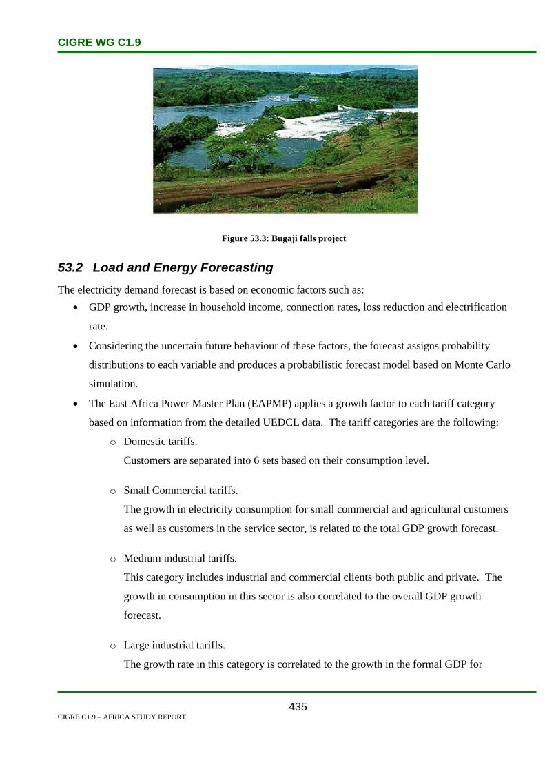
CIGRE WG C1.9
CIGRE C1.9 – AFRICA STUDY REPORT
435
Figure 53.3: Bugaji falls project
53.2 Load and Energy Forecasting
The electricity demand forecast is based on economic factors such as:
GDP growth, increase in household income, connection rates, loss reduction and electrification
rate.
Considering the uncertain future behaviour of these factors, the forecast assigns probability
distributions to each variable and produces a probabilistic forecast model based on Monte Carlo
simulation.
The East Africa Power Master Plan (EAPMP) applies a growth factor to each tariff category
based on information from the detailed UEDCL data. The tariff categories are the following:
o Domestic tariffs.
Customers are separated into 6 sets based on their consumption level.
o Small Commercial tariffs.
The growth in electricity consumption for small commercial and agricultural customers
as well as customers in the service sector, is related to the total GDP growth forecast.
o Medium industrial tariffs.
This category includes industrial and commercial clients both public and private. The
growth in consumption in this sector is also correlated to the overall GDP growth
forecast.
o Large industrial tariffs.
The growth rate in this category is correlated to the growth in the formal GDP for

CIGRE WG C1.9
CIGRE C1.9 – AFRICA STUDY REPORT
436
manufacturing forecast.
The high and low forecasts are based on different growth rates in the number of domestic clients, as
well as on different scenarios regarding economic growth. The results are shown in Tables 53.1, 53.2
and Figures 53.2, 53.3 below.
Table 53.1: Basis Assumptions for the Uganda Load Forecast
Source SSEA II – Regional Power Needs Assessment
Table 53.2: Uganda Forecast Summary
Source SSEA II – Regional Power Needs Assessment

CIGRE WG C1.9
CIGRE C1.9 – AFRICA STUDY REPORT
437
Figure 53.4: Demand Forecast in Uganda
Source SSEA II – Regional Power Needs Assessment
Figure 53.5: Energy Forecast in Uganda
Source SSEA II – Regional Power Needs Assessment

CIGRE WG C1.9
CIGRE C1.9 – AFRICA STUDY REPORT
438
53.3 Planning and Design Criteria
A Grid Code is available.
The grid system criteria are based on maintaining the reliability and continuity of supply:
Capacity regulation.
Voltage control (±6% at low voltage).
Time and frequency regulation.
Frequency shall be maintained at 50 Hz (±0.5 Hz).
Inadvertent interchange management.
Most of the electricity is generated from hydro power stations. The installed capacity is about 317
MW. The prolonged drought in the region has resulted in low lake levels, reducing the effective
generation capacity from the main power stations of Kiira and Nalubale to 190 MW.
To reduce the power deficit during peak hours, a 50 MW thermal plant has been procured and has been
in operation since May 2005. The current peak demand is now estimated at about 330 MW.
With the current generation capacity, there is a deficit of about 100 MW during peak hours, which
necessitates load shedding. An additional capacity of 100 MW is therefore to be installed in the course
of 2006.
Since 2005, the supply of electricity in Uganda is from the following sources:
Table 53.3: Electricity Supply by Source
Source Effective Capacity MW
Kira and Nalubale power stations 190
Cogeneration 8
Small hydro power stations 20
Thermal generation 50
53.4 Planning Approaches and Methods
The demand for electricity in Uganda is growing at an average of 8% per annum, or about 24 MW per
year.
In the medium term, the Government is looking at the development of Victoria Nile hydropower sites
like Bujagali and Karuma. There is also a need to have significant investment in the distribution and
transmission networks.

CIGRE WG C1.9
CIGRE C1.9 – AFRICA STUDY REPORT
439
The current and planned generation mix for short term measures are:
An addition of 100 MW of thermal generation in 2007,
Under the Energy for Rural Transformation programme, about 70 MW of electricity will be
generated from renewable energy sources (such sources include mini hydros, bagasse, crop
residues, etc.),
Bujagali Power Project will be developed to provide 250 MW by 2010, and
Karuma Power Station will be developed by 2012 to add about 200 MW.
Most of new generation capacity will be provided competitively by the private sector.
In terms of network infrastructure development, there is:
A total of 1 115 km of 132 kV transmission lines and 54 km of 66 kV transmission lines in the
country.
The distribution facilities include 3 258 km of 33 kV lines, 3 443 km of 11 kV lines and
6 496 km of low voltage lines. This network provides power to only 33 of the 56 districts in the
country.
The Uganda Electricity Transmission Company Limited has export contract obligations to
neighbouring countries as follows:
Kenya (30 MW),
Tanzania (9 MW), and
Rwanda (5 MW).
The 30 MW to Kenya is supplied only during off-peak hours, and only 9 MW and 5 MW exports go to
Tanzania and Rwanda respectively. However, arrangements have been finalized for Uganda to export
a firm capacity of 50 MW to Kenya from 2006, after the commissioning of the Bujagali Project.
53.5 Specific Technical Issues
No discussion on specific technical issues was presented.
53.6 Financing Issues
Funds for Uganda electricity projects are secured from different sources, some of them are:
The East African Development Bank,
African Development Bank,
Financing Company of Uganda (DFCU), and

CIGRE WG C1.9
CIGRE C1.9 – AFRICA STUDY REPORT
440
The World Bank through the ERT programme.
53.7 Human Resources
No discussion on human resources issues was presented.

CIGRE WG C1.9
CIGRE C1.9 – AFRICA STUDY REPORT
441
54. Western Sahara
54.1 Electricity Industry Structure
Western Sahara is a nation in northern Africa, bordering the north Atlantic Ocean, between Mauritania
to the south and Morocco to the north.It is mostly low, flat desert with large areas of rocky or sandy
surfaces rising to small mountains in south and northeast.Sparse water and lack of arable land.It is
susceptible to the hot , dry, dust/sand-laden sirocco wind which can occur during winter and spring;and
also , widespread harmattan haze which exist 60% of time, often severely restricting visibility.The
size of Western Sahara is 266 000 km2. The population is estimated at 393 831.
In 2005 electricity been generated was 0.085 MWh and the consumption of energy was 0.079
MWh.The total kilowatts per person was 235. The kingdom of Morrocco is preparing a major solar
power project on five sites – Laayoune(Sahara), Boujdour(Western Sahara), Tarfaya (Soth of Agadir),
Ain Beni mathar(center) and Ouarzazate – with state of the art solar facilities composed of
photovoltaic and solar thermal energy mechanisms.In total the five sites will produce up to 2000 MW
of electricity.Consenquently, one millon tons of oil will be saved annually according to Minister of
Energy, Amina Benkhadra.Renewable energy is attractive as most sites in Morocco depends entirely
on imported energy.This will also reduce the national fuel bill and greenhouse emissions, which in turn
will benefit the environment.The use of solar energy is also expected to generate other solar research
programmes.The African Development Bank is one of the partners in this huge project, which is
promoting the broadening of the supply of low-cost environmentally clean energy to more people and
developing renewable forms of energy to diversify the sources for generating electric power. No
discussion on ESI structure issues was presented. [1]

CIGRE WG C1.9
CIGRE C1.9 – AFRICA STUDY REPORT
442
Figure 54.1: Electricity consumption between 2000 and 2011
Figure 54.2: Electricity production between 2000 and 2011
54.2 Load and Energy Forecasting
No discussion on load forecast issues was presented.
GWh
GWh
CIGRE WG C1.9
CIGRE C1.9 – AFRICA STUDY REPORT
443
54.3 Planning and Design Criteria
No discussion on planning and design criteria issues was presented.
54.4 Planning Approaches and Methods
No discussion on planning approach issues was presented.
54.5 Specific Technical Issues
No discussion on financing issues was presented.
54.6 Financing Issues
No discussion on financing issues was presented.
54.7 Human Resources
No discussion on human resource issues was presented.
54.8 References
1. www.mbendi.com

CIGRE WG C1.9
CIGRE C1.9 – AFRICA STUDY REPORT
444
55. Zambia
55.1 Electricity Industry Structure
Zambia is located in southern central Africa and neighbours the Democratic Republic of Congo,
Tanzania, Malawi, Mozambique, Zimbabwe, Botswana, Namibia and Angola. Zambia’s population is
estimated at 11.7 million in 2005, and has an area of 752 618 km2.
Zambia is endowed with many types of energy sources including woodlands and forests, hydropower,
coal and new and renewable sources of energy.
The hydropower resource potential is estimated at 6 000 MW.
Total installed capacity is about 1 800 MW.
Hydroelectric plants represent 92% of the installed capacity and account for 99% of electricity
production.
The load density per capita is 0.163 kW per person.
Zambia’s main electricity power players are:
Zambia Electricity Supply Corporation (ZESCO), which:
o Is a vertically integrated state owned utility,
o Owns and operates the power generation, transmission , distribution and supply
businesses, and
o Sells bulk power to the Copperbelt Energy Corporation (CEC).
Copperbelt Energy Corporation (CEC):
o An IPP company that owns and operates the transmission and distribution power
network in the Copperbelt Province of Zambia.
Lunsemfwa Hydro Power Company (LHPC):
o Owns the hydro power generation facilities of 38 MW in Central Province.
The Energy Regulation Board (ERB):
o Is the sole licensing authority for operators in the energy sector and is responsible for
close monitoring and supervision of such operators.
o Promotes competition and ease of entry into the energy sector as well as safeguarding
consumer interests.
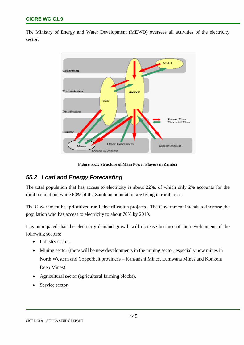
CIGRE WG C1.9
CIGRE C1.9 – AFRICA STUDY REPORT
445
The Ministry of Energy and Water Development (MEWD) oversees all activities of the electricity
sector.
Figure 55.1: Structure of Main Power Players in Zambia
55.2 Load and Energy Forecasting
The total population that has access to electricity is about 22%, of which only 2% accounts for the
rural population, while 60% of the Zambian population are living in rural areas.
The Government has prioritized rural electrification projects. The Government intends to increase the
population who has access to electricity to about 70% by 2010.
It is anticipated that the electricity demand growth will increase because of the development of the
following sectors:
Industry sector.
Mining sector (there will be new developments in the mining sector, especially new mines in
North Western and Copperbelt provinces – Kansanshi Mines, Lumwana Mines and Konkola
Deep Mines).
Agricultural sector (agricultural farming blocks).
Service sector.

CIGRE WG C1.9
CIGRE C1.9 – AFRICA STUDY REPORT
446
Figures 55.2 and 55.3 show the projected electricity demand forecast and energy forecast in Zambia
respectively.
Figure 55.2: The Projected Electricity Demand Forecast in Zambia
Figure 55.3: Energy Forecast in Zambia
Load forecast methodologies employed by Zambia include;
historical trends.
electrification target.
bottom-up approach.

CIGRE WG C1.9
CIGRE C1.9 – AFRICA STUDY REPORT
447
55.3 Planning and Design Criteria
In the electricity sector, generation of power in Zambia is dominated by hydro. The country has hydro
generating potential of about 6 000 MW, however the country’s installed capacity is only about
1 780 MW. This capacity mainly consists of three large power stations at Kafue Gorge (900 MW),
Kariba North Bank (600 MW) and Victoria Falls (108 MW).
Zambia has a maximum demand load of 1 755 MW. Out of this, ZESCO contributes 1 640 MW from
three large hydro sites (1 608 MW), four mini hydro sites (23.75 MW) and 8 conventional diesel sites
(8.585 MW). CEC owns and operates 80 MW of stand-by diesel based gas turbine generators.
Lunsemfwa Hydro Power contributes 38 MW with two medium hydro generators, and KCM operates
20 MW from one waste steam site. It is worth noting that when the Power Rehabilitation Project is
completed, the capacity of Kafue Gorge will increase from 900 MW to 990 MW and the capacity of
Kariba will increase from 600 MW to 720 MW.
93%
2% 4% 1%
Zasco LHPC CEC KCM
Figure 55.4: Electricity Supply by Source
55.4 Planning Approaches and Methods
Local electricity demand/consumption growth is anticipated to continue, and the existing capacity is
envisaged to be exhausted around 2007/08.
To meet the growing future demand, Zambia has been developing several projects. Among others, are
the Itezhi-Tezhi and the Kafue Gorge Lower, as well as the rehabilitation programme of Victoria Falls,
Kariba North, and Kafue Gorge power stations.
Table 55.1 summarizes Zambia’s generation projects:

CIGRE WG C1.9
CIGRE C1.9 – AFRICA STUDY REPORT
448
Table 55.1: Summary of Generation Projects
Project
Capacity MW
Estimated
Commencement Year
Kariba North Bank
Extension
360 2010
Itezhi Tezhi Power Station 120 2010
Kafue Gorge Lower 600–750 2013
Transmission expansion or new transmission systems are dependent on the development of new
generation sites.
Current and future generation and transmission in Zambia is shown in Figure 55.5.
Figure 55.5: Zambia’s Power Network

CIGRE WG C1.9
CIGRE C1.9 – AFRICA STUDY REPORT
449
Zambia plays a strategic role in the Southern African Power network. Presently, Zambia is a net
exporter of electricity and conducts its trade with the Democratic Republic of Congo, Namibia and
South Africa.
Preparatory work for the interconnection between Zambia, Tanzania and Kenya is almost complete.
55.5 Specific Technical Issues
The largest power source of generation in Zambia is traditional biomass. Residential energy use
consists primarily of wood-fuel. No new renewable sources like geothermal or wind are present in
Zambia [1]. Since 1997, ZESCO has been working to achieve standardization for stable and reliable
power supply and enhancement of services for consumers. Technical standards for
transmission/distribution facilities and electricity meters to be provided to consumers are based on the
technical standards of the International Electrotechnical Commission (IEC). Service manuals have also
been prepared for speedy and efficient consumer service. Everything has been computerized into the
Business Information System (BIS), enabling easy access on our computer screens [2].
55.6 Financing Issues
ZESCO’s monthly turnover is US$20 million per month or US$240 million per annum. The company
is valued at US$3.0 billion and is currently undergoing a rehabilitation project for the generating
stations. It is expected that the company will be revalued when the rehabilitation is complete. The
power rehabilitation project is a US$ 335 million project. The original budget was US$ 206 million.
ZESCO’s total contribution, excluding running costs, is US$ 56 million. The Government of Zambia
has contributed US$49 million. The balance of the money has come from a combination of the World
Bank, Sida, European Investment Bank and Development Bank of Southern Africa.
The recent transmission projects that ZESCO has completed, such as the 330 kV Luano-Kansanshi line
and the 330 kV Kansanshi-Lumwana line, were financed by loans obtained from the local branches of
international banks such as Barclays and Standard Chartered Bank.
The 220 kV line between Livingstone in Zambia and Katima in Namibia was financed jointly by the
Development Bank of Southern Africa, ZESCO and Nampower.
For the new generation projects at Itezhi-Tezhu, ZESCO has formed a joint venture company with
TATA Africa. The project is to be financed via loans from the open market and possibly from the
Exim Bank of India. The project has commenced and is on track to commissioned by 2010.

CIGRE WG C1.9
CIGRE C1.9 – AFRICA STUDY REPORT
450
For the Kariba North Extension, the bulk of the money is to come from the China Exim Bank (85%).
The balance will be secured from other sources. This project has commenced and is expected to be
complete by 2010.
55.7 Human Resources
ZESCO has an establishment of about 3 900 permanent employees. ZESCO has a presence in every
district of the country.
ZESCO is divided into seven directorates headed by Directors, namely:
Generation and Transmission.
Distribution and Supply.
Engineering Development.
Power Rehabilitation Projects/New Generation Projects.
Customer Services.
Finance.
Human Resources.
ZESCO is governed through an independent board of directors, which is appointed by the government
and ratified by parliament. The Ministry of Finance holds the shareholding and the Ministry of Energy
has a supervisory role. The Managing Director and Directors are entrusted with the day-to-day
management of the company. The chart below shows the structure of governance of the company.
Figure 55.6: ZESCO Top Management Structure

CIGRE WG C1.9
CIGRE C1.9 – AFRICA STUDY REPORT
451
55.8 References
1. 061129%20RECIPES%20country%20info%20Zambia
2. Zambia-Chapter%204-C

CIGRE WG C1.9
CIGRE C1.9 – AFRICA STUDY REPORT
452
56. Zimbabwe
56.1 Electricity Industry Structure
Zimbabwe is a member of the SADC and is a landlocked country in Southern Africa bordered by
South Africa, Mozambique, Botswana and Zambia.
It has a population of about 13.2 million people (2005) and a land area of 390 800 km².
The economy relies heavily on agricultural crops such as tobacco, cotton, and sugarcane, and on
manufacturing industries such as steel, textiles and sugar production.
Mining is a major activity, primarily gold.
Load density per capita 0.133 kw/person.
Only 18% of the rural population has access to electricity. The government has enacted new
legislation that is targeted at accelerating rural electrification. Under the Expanded Rural
Electrification Programme (EREP), it now becomes mandatory for the government, through the local
utility Zimbabwe Electricity Supply Authority (ZESA), to allocate resources to the widespread rural
electrification drive without considering the economic merit of the grid extension.
Figure 56.1: Structure of the Electricity Supply Industry of Zimbabwe
MMIINNIISSTTEERR OOFF EENNEERRGGYY AANNDD PPOOWWEERR DDEEVVEELLOOPPMMEENNTT
NNaattiioonnaall
TTrraannssmmiissssiioonn
CCoommppaannyy
NNaattiioonnaall
DDiissttrriibbuuttiioonn
CCoommppaannyy
PPoowweerrTTeell
ZZEESSAA HHOOLLDDIINNGGSS ((PPvvtt)) LLttdd
ZZEESSAA
EEnntteerrpprriisseess
NNaattiioonnaall
GGeenneerraattiioonn
CCoommppaannyy

CIGRE WG C1.9
CIGRE C1.9 – AFRICA STUDY REPORT
453
Figure 56.2: Electricity Regulatory Structure of Zimbabwe
The electricity sector is the sole supply domain of the Zimbabwe Electricity Supply Authority, ZESA.
ZESA generates, imports and distributes all electrical energy in the country, except for a few small
private generators run either as stand-alone systems in remote communities or as back-up systems by
large urban companies, and in some schools and hospitals.
Electricity power generation in Zimbabwe is mainly from coal and hydro plants. The power source
facilities do not meet the country’s electricity demand. As a result, Zimbabwe imports 30% of its
electricity from neighbouring countries, including the DRC, Mozambique, Zambia and South Africa.
Reforms in the electricity industry are being implemented.
56.2 Load and Energy Forecasting
Energy consumption has grown at an average rate of about 3.5% per annum since 1990, which has
exceeded the GDP growth rate of 2.7%.
The demand for energy comes primarily from residential (59%), followed by industry (18%),
agriculture (13%), commerce (7%), and mining (3%).
The high energy consumed in residential areas comes from wood fuel used.
Independent Power Producers (IPP’s)
Local Generators
Southern African Power Pool (SAPP)
Transmission/Grid Company + Electricity Market Operator
Distribution and
Supply Company Rural Electrification
Agency (REF)
Large Customers (+ 25 MVA)
Retail, Commercial, Industrial, Agricultural and Domestic Customers
Zimbabwe Electricity Regulatory
Commission
(ZERC)
Key Regulation and Control by ZERC
Flow of Electricity

CIGRE WG C1.9
CIGRE C1.9 – AFRICA STUDY REPORT
454
59%18%
13%
7% 3%
Residential Industry agriculture Commerce Mining
Figure 56.3: Energy Demand by Sector in Zimbabwe
Load forecast methodologies employed by Zimbabwe include;
historical trend.
electrification targets, and
bottom-up approach.
Figure 56.4: Demand and Energy Forecast for Zimbabwe

CIGRE WG C1.9
CIGRE C1.9 – AFRICA STUDY REPORT
455
56.3 Planning and Design Criteria
No discussion on planning and design criteria issues was presented
56.4 Planning Approaches and Methods
Zimbabwe is connected to the Southern African Power Pool (SAPP) grid and imports 30% of its
electricity from neighbouring countries, including:
Democratic Republic of Congo (DRC).
Mozambique.
Zambia, and
South Africa.
Table 56.1 summarizes some of the planned generation projects.
Table 56.1: Zimbabwe’s Planned Generation Projects
Project Name Capacity (MW) Type Expected
Commissioning Year
Kariba South 300 Hydro 2007
Hwange 7& 8 660 2008
Lupani 300 Gas 2009
Western Power
Station
1 200 Coal 2008
Gogwe North 1 400 Thermal

CIGRE WG C1.9
CIGRE C1.9 – AFRICA STUDY REPORT
456
Figure 56.5: Planned Short Term Generation Projects – Zimbabwe

CIGRE WG C1.9
CIGRE C1.9 – AFRICA STUDY REPORT
457
Figure 56.6: Zimbabwe Grid with Proposed Projects
Table 56.2 summarizes Zimbabwe’s power imports:
Table 56.2: Zimbabwe Power Imports
Country Interconnection
Voltage kV
Maximum Capacity
MW
Available Capacity
MW
Mozambique 400 500 500
South Africa 400 500 150–500
Zambia 330 700 100–200
DRC 220 250 150
56.5 Specific Technical Issues
No discussion on specific technical issues was presented. The Zimbabwe Electricity Supply Authority
(ZESA) has been responsible for the generation, transmission and distribution of electricity in
Zimbabwe for a long time now. It has five major power stations, with a total capacity of 1 961 MW

CIGRE WG C1.9
CIGRE C1.9 – AFRICA STUDY REPORT
458
(Karekezi, et al, 2002). These facilities do not meet the country’s electricity demand. As a result,
Zimbabwe imports 41 per cent of its electricity from neighbouring countries, including DRC,
Mozambique, Zambia and South Africa (as shown in Table 4). Electricity generation in Zimbabwe is
mainly from coal and hydro plants, the former with a capacity of 1 170 MW. The largest hydro plant is
Kariba, which generates 500 MW (ZESA 2001). [1]
Table 56.3: Zimbabwe Power imports[1]
Table 56.4: Internal supply of electricity within Zimbabwe[1]
56.6 Financing Issues
No discussion on financing issues was presented. Zimbabwe is a poverty stricken nation. The
economic problems are endless and leave the energy production/ electricity departments with little
finance to upgrade the network.
Disadvantages areas in Zimbabwe are in a difficult situation with regards to electricity supply.
Resources are low which leaves very little hope of attaining power for those who live in these areas.

CIGRE WG C1.9
CIGRE C1.9 – AFRICA STUDY REPORT
459
56.7 Human Resources
No discussion on human resource issues was presented. Zimbabwe is a nation struggling to keep up
with the exponential economic growth. The Government has the intention of providing job
opportunities and education to assist in eradicating poverty.
Since attaining independence in 1980, Zimbabwe has embarked on various sector policy reforms,
including energy sector reforms. The Government has sought to increase energy access to previously
disadvantaged people through both grid extension and off-grid electrification. The national energy
policy has five main objectives (Munjeri, 2002. Two of the objectives focusing on rural development
and small/medium scale enterprises have an explicit emphasis on the poor:
(a) Ensuring accelerated economic development;
(b) Facilitating rural development;
(c) Promoting small-medium scale enterprises;
(d) Ensuring environmentally friendly energy development; and
(e) Ensuring efficient utilisation of energy resources.
Zimbabwe’s power sector has undergone a number of changes since independence. Generally
speaking, four main drivers have been behind power sector reforms in Zimbabwe (Turkson, 2002) with
one of the drivers explicitly focussed on the needs of the poor:
Restructuring as a component of the general economic reforms;
Reforming parastatals to empower historically marginalized groups;
Enhancing power sector efficiency; and
Mobilizing finance for capital investments in the power sector.
In 1985, the Government reformed the structure of power utilities under the Electricity Act. Five
publicly owned power utilities were amalgamated to form the current Zimbabwe Electricity Supply
Authority (ZESA) with the aim of streamlining the administration of the electricity sector, improving
efficiency, standardizing tariffs and reducing duplication of functions. ZESA became the only legal
entity with the right to generate and transmit electricity. It had the option of licensing independent
power producers to generate electricity and also the right to set the purchase price of electricity from
the producers. The Act did not provide room for third party access, nor for other uses of the grid by
third parties (ESMAP, 2000).
56.8 References
1. http://www.afrepren.org/project/gnesd/esdsi/erc.pdf
2. http://en.wikipedia.org/wiki/Zimbabwe_Electricity_Supply_Authority
CIGRE WG C1.9
CIGRE C1.9 – AFRICA STUDY REPORT
460
57. Conclusion and Recommendations
The workgroup would like to thank all those who contributed to this report, including the many
country paper submissions that were received. This document can serve as a valuable benchmarking
resource, and for obtaining information. It should be updated and enhanced in the years to come, to
serve as repository for use by planning engineers and others across Africa.
The following workgroups are recommended for continuation of the work done by C1.9:
Future major interconnections in Africa
Study of the use of renewable energy in Africa to meet load growth, and tapping into the vast
hydro, solar, geothermal and wind resources.
Study the financing challenges facing African countries, similar to the work done by the world
bank in releasing the book in 2011 entitled “Africa’s Power Infrastructure - Investment,
Integration, Efficiency”
It is also recommended that CIGRE C1 be represented in the SCIENTIFIC COMMITTEE of UPDEA
which deals with power system development. A joint CIGRE & UPDEA symposium can be convened,
were work done by C1 and C1.9 can be shared with African Countries, and vice versa. The last such
CIGRE & UPDEA joint Symposium was in 1985 in Dakar, more than 25 years ago, hence this is long
overdue.

CIGRE WG C1.9
CIGRE C1.9 – AFRICA STUDY REPORT
461
Appendix 1
Email Contact List
[email protected] Algeria
[email protected] Algeria
[email protected] Algeria
[email protected] Angola
[email protected] Angola
[email protected] Angola
[email protected] Angola
[email protected] Angola
[email protected] Angola
[email protected] Angola
[email protected] Angola
[email protected] Benin
[email protected] Benin
[email protected] Benin
[email protected] Benin
[email protected] Botswana
[email protected] Botswana
[email protected] Botswana
[email protected] Botswana
[email protected] Botswana
[email protected] Botswana
[email protected] Botswana
[email protected] Burkina Faso
[email protected] Burkina Faso
[email protected] Burkina Faso
[email protected] Burkina Faso
[email protected] Burkina Faso
[email protected] Cameroon
[email protected] Congo
[email protected] Congo
[email protected] Côte Ivoire
[email protected] Côte Ivoire
[email protected] Democratic Republic of Congo DRC
[email protected] Egypt
[email protected] Eritrea
[email protected] Ethiopia

CIGRE WG C1.9
CIGRE C1.9 – AFRICA STUDY REPORT
462
[email protected] Gambia
[email protected] Ghana
[email protected] Ghana
[email protected] Ghana
[email protected] Kenya
[email protected] Kenya
[email protected] Kenya
[email protected] Kenya
[email protected] Kenya
[email protected] Kenya
[email protected] Kenya
[email protected] Kenya
[email protected] Kenya
[email protected] Lesotho
[email protected] Lesotho
[email protected] Liberia
[email protected] Libya
[email protected] Malawi
[email protected] Malawi
[email protected] Malawi
[email protected] Malawi
[email protected] Malawi
[email protected] Mali
[email protected] Mauritius
[email protected] Mauritius
[email protected] Mauritius
[email protected] Morocco
[email protected] Morocco
[email protected] Morocco
[email protected] Morocco
[email protected] Mozambique
[email protected] Namibia
[email protected] Namibia
[email protected] Namibia
[email protected] Namibia
[email protected] Niger
[email protected] Niger
[email protected] Niger
[email protected] Nigeria
[email protected] Nigeria
CIGRE WG C1.9
CIGRE C1.9 – AFRICA STUDY REPORT
463
[email protected] Rwanda
[email protected] SAPP
[email protected] Senegal
[email protected] Senegal
[email protected] Senegal
[email protected] Senegal
[email protected] Senegal
[email protected] Senegal
[email protected] South Africa
[email protected] South Africa
[email protected] South Africa
[email protected] South Africa
[email protected] Sudan
[email protected] Sudan
[email protected] Tanzania
[email protected] Tanzania
[email protected] Tanzania
[email protected] Tanzania
[email protected] Tunisia
[email protected] Uganda
[email protected] Zambia
[email protected] Zambia
[email protected] Zambia
[email protected] Zambia
[email protected] Zambia
[email protected] Zambia
[email protected] Zambia
[email protected] Zambia
[email protected] Zambia
[email protected] Zimbabwe
[email protected] Zimbabwe
[email protected] Zimbabwe

CIGRE WG C1.9
CIGRE C1.9 – AFRICA STUDY REPORT
464