week 14 - lecture cfd analysis - carnegie mellon university 14 - cfd... · week 14 - lecture cfd...
TRANSCRIPT

ME 24-688 Introduction to CAD/CAE Tools
Week 14 - Lecture
CFD Analysis

ME 24-688 Introduction to CAD/CAE Tools
Lecture Topics
• Team Project 2 Discussion
• Simulation Drivers
• CFD Overview
• CFD Use Cases and Examples
• Common Requirements for CFD
• Introduction to Autodesk CFD Products

ME 24-688 Introduction to CAD/CAE Tools
Simulation
• Simulation offers the potential to improve
products by predicting behavior digitally.

ME 24-688 Introduction to CAD/CAE Tools
Understanding Product Behavior
Source: Aberdeen Group: How Best-in-Class Companies Amplify Engineering with CFD, April 2011
Business needs and challenges of understanding product behavior.

ME 24-688 Introduction to CAD/CAE Tools
CFD Overview
• Computational Fluid Dynamics (CFD) is a
specialized simulation that analyzes fluid
flow. Used to analysis the interaction of
liquids and gases with surfaces defined by
boundary conditions.

ME 24-688 Introduction to CAD/CAE Tools
Products that Benefit from CFD
• Liquid or Gas Flow
• Heating and Cooling
• Chemical Reactions
• Turbulence
• Aerodynamics

ME 24-688 Introduction to CAD/CAE Tools
Leading Impact of Not Using CFD
Source: Aberdeen Group: How Best-in-Class Companies Amplify Engineering with CFD, April 2011

ME 24-688 Introduction to CAD/CAE Tools
CFD Use Case Examples
• Airflow cooling of consumer electronics.
• Aerodynamics and down force of a vehicle.
• Fluid flow efficiency through piping valve.

ME 24-688 Introduction to CAD/CAE Tools
CFD Example

ME 24-688 Introduction to CAD/CAE Tools
Reducing Energy Loss in Design
http://sustainabilityworkshop.autodesk.com/strategy/fluid-dynamics

ME 24-688 Introduction to CAD/CAE Tools
Fluid Model
• There needs to be a model created that
represents the fluid volume.

ME 24-688 Introduction to CAD/CAE Tools
CFD Elements
• Fluid flow analysis generally support 2D and
3D elements. 3D fluid flow elements have
4, 5, 6, and 8 node elements like bricks.
ME 24-688 Introduction to CAD/CAE Tools
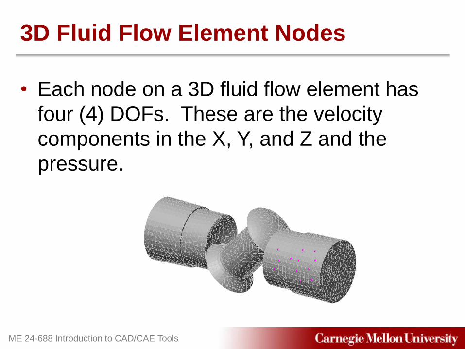
3D Fluid Flow Element Nodes
• Each node on a 3D fluid flow element has
four (4) DOFs. These are the velocity
components in the X, Y, and Z and the
pressure.

ME 24-688 Introduction to CAD/CAE Tools
Model Mesh (Boundary Layer)
• All Tetrahedra – Using all tetrahedra elements on a 3D model ensures high quality
interior mesh which is important for most fluid flow analysis.
Creating all 4 node elements can sometimes block a small area
near the exterior of the model impacting results.
• Tetrahedra and Wedge (Boundary Layer) – This option allows for a boundary mesh of just wedge elements to
be created at all of the exterior surfaces of the model. Tetrahedra
elements will then be used for the rest of the interior. This helps
capture the results more accurately around the walls of the model
and ensure no small areas are blocked with a single node.

ME 24-688 Introduction to CAD/CAE Tools
Common CFD Materials
• Liquids – Water
– Oils
– Ethanol
• Gases – Air
– Nitrogen
– Oxygen

ME 24-688 Introduction to CAD/CAE Tools
Common Fluid Flow Loads
• Inlet / Outlet – Specifies an input or output surface in most cases for which the
velocity is unknown and a zero-traction state is applied.
• Prescribed Velocity – Prescribed velocities establish the boundary conditions of a fluid
flow problem. Control and set the velocities for the X, Y, or Z DOFs
of the selected surface nodes.

ME 24-688 Introduction to CAD/CAE Tools
Common Results Types Provided
• Velocity – Displays the speed in a given direction of the fluid throughout the
model.
• Reaction Forces – Displays the reaction forces in the fluid model.
• Pressure – Displays the nodal based pressure results of the model.
• Flow Rate – Volumetric flow rate results provide positive values for flow into an
element and negative rates represents flow out of the element.

ME 24-688 Introduction to CAD/CAE Tools
Particle Paths
• Particle paths track the movement of a
massless particle in the fluid flow model
from select nodes.

ME 24-688 Introduction to CAD/CAE Tools
Streamlines
• Streamlines show the flow through a node
during a fluid flow analysis from selected
nodes.

ME 24-688 Introduction to CAD/CAE Tools
Autodesk CFD Products
• Autodesk Simulation – Full range of simulation tools including general CFD analysis.
• Autodesk Simulation CFD – Comprehensive set of tools for fluid flow and thermal simulation.
(formerly known as CFdesign)
• Project Falcon Wind Tunnel Simulation – Autodesk Labs (labs.autodesk.com) free technology preview that
provide wind tunnel simulation for aerodynamic performance.

ME 24-688 Introduction to CAD/CAE Tools
Project Falcon
http://www.youtube.com/watch?v=UrrOA0rlaCg

ME 24-688 Introduction to CAD/CAE Tools
Reminder - Motion in CFD Impact
• Flow-Driven Motion – Object moves or stops in response to fluid impingement or
resistance.
• Mechanical-Driven Motion – Object is in motion but does not react to the flow, but instead moves
in a completely specified direction over a defined time and
direction.

ME 24-688 Introduction to CAD/CAE Tools
Limitations of CFD
• Separate Fluid Domains – No mixture of different fluids
• Viscous Fluids – Non-zero friction
• Incompressible Material – Constant Density
• Isothermal – Material properties are independent of temperature

ME 24-688 Introduction to CAD/CAE Tools
Guided Lab Project 1
• Guides instructions for completing an
unsteady internal fluid flow analysis.

ME 24-688 Introduction to CAD/CAE Tools
Guided Lab Project 2
• Guided instructions for completing an
unsteady external fluid flow analysis.

ME 24-688 Introduction to CAD/CAE Tools
Guided Lab Project 3
• Guided instructions for completing unsteady
fluid flow with additional loading options for
a value component.

ME 24-688 Introduction to CAD/CAE Tools
Problem Set Assignment
• Complete CFD analysis on value assembly
to determine impact of performance from
improper assembly.