· welcometobmw congratulations on choosing a motorcycle from bmw motorrad and welcome to the...
TRANSCRIPT
Rider's Manual (US Model)
S 1000RR
BMW Motorrad
The UltimateRiding Machine

Motorcycle/Retailer Data
Motorcycle Data
Model
Vehicle identification number
Color number
Initial registration
License plate
Retailer Data
Contact in Service
Ms./Mr.
Phone number
Retailer's address/phone number (com-pany stamp)

Welcome to BMW
Congratulations on choosing amotorcycle from BMW Motorradand welcome to the communityof BMW motorcycle owners andriders. Familiarize yourself withyour new motorcycle so that youcan ride it safely and confidentlyin all highway traffic situations.
About this Rider's ManualPlease read this Rider's Manualcarefully before starting to useyour new BMW. It contains im-portant information on how tooperate the controls and how toget the most benefit from yourBMW's advanced technical fea-tures.In addition, it contains informa-tion on maintenance and care tohelp you maintain your vehicle'sreliability and safety, as well as itsvalue.
Suggestions and complaintsIf you have any questions con-cerning your motorcycle, your au-thorized BMW Motorrad retaileris always happy to provide adviceand assistance.
We wish you many miles of safeand enjoyable riding on yourBMW
BMW Motorrad.
01 41 8 565 387
*01418565387**01418565387**01418565387*

Table of Contents
1 General instructions . . . . 5Overview . . . . . . . . . . . . . . . . . . . . . 6Abbreviations andsymbols . . . . . . . . . . . . . . . . . . . . . . 6Equipment . . . . . . . . . . . . . . . . . . . 7Technical data . . . . . . . . . . . . . . . 7Notice concerning current sta-tus . . . . . . . . . . . . . . . . . . . . . . . . . . . 7
2 Overviews . . . . . . . . . . . . . . . . 9General view, left side . . . . . . . 11General view, left side withDDC . . . . . . . . . . . . . . . . . . . . . . . . 13General view, right side . . . . . 15Multifunction switch, left . . . . 16Multifunction switch,right . . . . . . . . . . . . . . . . . . . . . . . . . 18Underneath seat . . . . . . . . . . . . 19Instrument cluster . . . . . . . . . . . 20
3 Displays . . . . . . . . . . . . . . . . . 21Warning and indicatorlights . . . . . . . . . . . . . . . . . . . . . . . . 22Multifunction display . . . . . . . . 23Warning lights . . . . . . . . . . . . . . . 24
4 Operation. . . . . . . . . . . . . . . . 39Steering and ignitionlock . . . . . . . . . . . . . . . . . . . . . . . . . 40Ignition . . . . . . . . . . . . . . . . . . . . . . 40Electronic immobilizer . . . . . . . 41Emergency on/off switch (killswitch) . . . . . . . . . . . . . . . . . . . . . . 41Lights . . . . . . . . . . . . . . . . . . . . . . . 42Hazard warning flashers . . . . . 43Turn indicator . . . . . . . . . . . . . . . 43Multifunction display . . . . . . . . 45Alarm system . . . . . . . . . . . . . . . 48Clock . . . . . . . . . . . . . . . . . . . . . . . . 50Anti-Lock Brake System . . . . 50Automatic Stability Con-trol . . . . . . . . . . . . . . . . . . . . . . . . . . 51Dynamic TractionControl . . . . . . . . . . . . . . . . . . . . . . 52Riding mode . . . . . . . . . . . . . . . . 53
Cruise control . . . . . . . . . . . . . . . 57Speed warning . . . . . . . . . . . . . . 59Heated handlebar grips . . . . . 60Rider and passengerseats . . . . . . . . . . . . . . . . . . . . . . . . 61Helmet holder . . . . . . . . . . . . . . . 63Luggage straps . . . . . . . . . . . . . 64
5 Setting . . . . . . . . . . . . . . . . . . . 65Mirrors . . . . . . . . . . . . . . . . . . . . . . 66Headlight . . . . . . . . . . . . . . . . . . . . 66Brakes . . . . . . . . . . . . . . . . . . . . . . 66Steering . . . . . . . . . . . . . . . . . . . . . 67Spring preload . . . . . . . . . . . . . . 67Damping . . . . . . . . . . . . . . . . . . . . 72DDC . . . . . . . . . . . . . . . . . . . . . . . . 75
6 Riding . . . . . . . . . . . . . . . . . . . . 79Safety instructions . . . . . . . . . . 80Observe checklist . . . . . . . . . . . 81Starting. . . . . . . . . . . . . . . . . . . . . . 82Breaking in . . . . . . . . . . . . . . . . . . 85Shifting gears . . . . . . . . . . . . . . . 87Brakes . . . . . . . . . . . . . . . . . . . . . . 88Parking your motorcycle . . . . 89
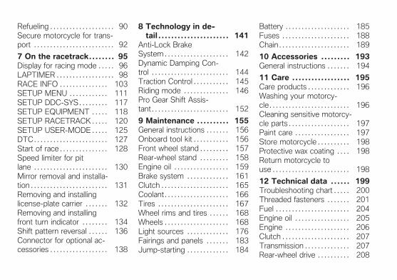
Refueling . . . . . . . . . . . . . . . . . . . . 90Secure motorcycle for trans-port . . . . . . . . . . . . . . . . . . . . . . . . . 92
7 On the racetrack. . . . . . . . 95Display for racing mode . . . . . 96LAPTIMER . . . . . . . . . . . . . . . . . . 98RACE INFO . . . . . . . . . . . . . . . 103SETUP MENU . . . . . . . . . . . . 111SETUP DDC-SYS . . . . . . . . . 117SETUP EQUIPMENT . . . . . 118SETUP RACETRACK . . . . . 120SETUP USER-MODE . . . . . 125DTC . . . . . . . . . . . . . . . . . . . . . . . 127Start of race . . . . . . . . . . . . . . . 128Speed limiter for pitlane . . . . . . . . . . . . . . . . . . . . . . . 130Mirror removal and installa-tion . . . . . . . . . . . . . . . . . . . . . . . . 131Removing and installinglicense-plate carrier . . . . . . . 132Removing and installingfront turn indicator . . . . . . . . 134Shift pattern reversal . . . . . . 136Connector for optional ac-cessories . . . . . . . . . . . . . . . . . . 138
8 Technology in de-tail . . . . . . . . . . . . . . . . . . . . . . 141
Anti-Lock BrakeSystem . . . . . . . . . . . . . . . . . . . . 142Dynamic Damping Con-trol . . . . . . . . . . . . . . . . . . . . . . . . 144Traction Control . . . . . . . . . . . 145Riding mode . . . . . . . . . . . . . . 146Pro Gear Shift Assis-tant . . . . . . . . . . . . . . . . . . . . . . . . 152
9 Maintenance . . . . . . . . . . 155General instructions . . . . . . . 156Onboard tool kit . . . . . . . . . . . 156Front wheel stand . . . . . . . . . 157Rear-wheel stand . . . . . . . . . 158Engine oil . . . . . . . . . . . . . . . . . 159Brake system . . . . . . . . . . . . . 161Clutch . . . . . . . . . . . . . . . . . . . . . 165Coolant . . . . . . . . . . . . . . . . . . . . 166Tires . . . . . . . . . . . . . . . . . . . . . . 167Wheel rims and tires . . . . . . 168Wheels . . . . . . . . . . . . . . . . . . . . 168Light sources . . . . . . . . . . . . . 176Fairings and panels . . . . . . . 183Jump-starting . . . . . . . . . . . . . 184
Battery . . . . . . . . . . . . . . . . . . . . 185Fuses . . . . . . . . . . . . . . . . . . . . . 188Chain . . . . . . . . . . . . . . . . . . . . . . 189
10 Accessories . . . . . . . . . 193General instructions . . . . . . . 194
11 Care . . . . . . . . . . . . . . . . . . 195Care products . . . . . . . . . . . . . 196Washing your motorcy-cle . . . . . . . . . . . . . . . . . . . . . . . . . 196Cleaning sensitive motorcy-cle parts . . . . . . . . . . . . . . . . . . . 197Paint care . . . . . . . . . . . . . . . . . 197Store motorcycle . . . . . . . . . . 198Protective wax coating . . . . 198Return motorcycle touse . . . . . . . . . . . . . . . . . . . . . . . . 198
12 Technical data . . . . . . 199Troubleshooting chart . . . . . 200Threaded fasteners . . . . . . . 201Fuel . . . . . . . . . . . . . . . . . . . . . . . 204Engine oil . . . . . . . . . . . . . . . . . 205Engine . . . . . . . . . . . . . . . . . . . . 206Clutch . . . . . . . . . . . . . . . . . . . . . 207Transmission . . . . . . . . . . . . . . 207Rear-wheel drive . . . . . . . . . . 208

Frame . . . . . . . . . . . . . . . . . . . . . 208Suspension . . . . . . . . . . . . . . . 209Brakes . . . . . . . . . . . . . . . . . . . . 209Wheels and tires . . . . . . . . . . 210Electrical system . . . . . . . . . . 211Dimensions . . . . . . . . . . . . . . . 213Weights . . . . . . . . . . . . . . . . . . . 213Performance data . . . . . . . . . 214
13 Service . . . . . . . . . . . . . . . 215Reporting safetydefects . . . . . . . . . . . . . . . . . . . . 216BMW Motorrad Service . . . 217BMW Motorrad MobilityServices . . . . . . . . . . . . . . . . . . . 217Maintenance proce-dures . . . . . . . . . . . . . . . . . . . . . . 217Maintenance schedule . . . . 221Standard BMW Service . . . 222Confirmation of mainte-nance work . . . . . . . . . . . . . . . . 223Confirmation of service . . . . 228
14 Appendix. . . . . . . . . . . . . 231Certificate for ElectronicImmobilizer . . . . . . . . . . . . . . . . 232
15 Index . . . . . . . . . . . . . . . . . 234

General instructions
Overview . . . . . . . . . . . . . . . . . . . . . . . . . . . . 6
Abbreviations and symbols . . . . . . . . . . 6
Equipment . . . . . . . . . . . . . . . . . . . . . . . . . . . 7
Technical data . . . . . . . . . . . . . . . . . . . . . . . 7
Notice concerning current status . . . . 7
15
z Ge
ne
ral i
nst
ruc
tio
ns

OverviewChapter 2 of this Rider's Man-ual will provide you with an ini-tial overview of your motorcycle.All maintenance and repair workcarried out on your motorcyclewill be documented in Chapter13. Documentation confirm-ing performance of scheduledmaintenance is a preconditionfor generous handling of out-of-warranty claims and goodwill war-ranty treatment.When the time comes to sellyour BMW, please rememberto hand over this Rider's Manual;it is an important part of the mo-torcycle.
Abbreviations andsymbols
CAUTION Hazard withlow risk. Failure to avoid
this hazard can result in minor ormoderate injury.
WARNING Hazard withmoderate risk. Failure to
avoid this hazard can result indeath or serious injury.
DANGER Hazard with highrisk. Failure to avoid this
hazard results in death or seriousinjury.
ATTENTION Special in-structions and precaution-
ary measures. Non-compliancecan cause damage to the vehi-cle or accessories and warrantyclaims may be denied as a result.
NOTICE Special informa-tion on operating and in-
specting your motorcycle as wellas maintenance and adjustmentprocedures.
Indicates the end of anitem of information.
Instruction.
Result of an activity.
Reference to a page withmore detailed informa-tion.
Indicates the end of ac-cessory or equipment-dependent information.
Tightening torque.
Technical data.
ABS Anti-Lock Brake System.
ASC Automatic Stability Con-trol.
DDC Dynamic Damping Con-trol.
DTC Dynamic Traction Con-trol.
16
z Ge
ne
ral i
nst
ruc
tio
ns

DWA Anti-theft alarm.
EWS Electronic immobilizer.
OE Optional extra.BMW Motorrad optionalextras are already com-pletely installed duringmotorcycle production.
OA Optional accessory.BMW Motorrad op-tional accessories canbe purchased and in-stalled at your autho-rized BMW Motorradretailer.
VDS Vertical Down Sensor(fall sensor).
EquipmentWhen you ordered your BMWmotorcycle, you chose variousitems of custom equipment. ThisRider's Manual describes optional
equipment (OE) offered by BMWand selected optional accessories(OA). This explains why the man-ual may also contain descriptionsof equipment which you have notordered. Please note, too, thatyour motorcycle might not be ex-actly as illustrated in this manualon account of country-specificdifferences.If your BMW is equipped withoptions or accessories not de-scribed in this Rider's Manual,then this equipment is describedin separate operating instructions.
Technical dataAll dimensions, weights and per-formance data contained thisRider's Manual refer to the Ger-man DIN standards and complywith their tolerance specifications.Versions for individual countriesmay differ.
Notice concerningcurrent statusThe high safety and quality stan-dards of BMW motorcycles aremaintained by consistent, on-going development efforts em-bracing their design, equipmentand accessories. For this reason,some aspects of your motorcyclemay vary from the descriptions inthis Rider's Manual. In addition,BMW Motorrad cannot guaranteethe total absence of errors. Wehope you will appreciate that noclaims can be recognized basedon the data, illustrations or de-scriptions in this manual.
17
z Ge
ne
ral i
nst
ruc
tio
ns

18
z Ge
ne
ral i
nst
ruc
tio
ns

Overviews
General view, left side . . . . . . . . . . . . . . . 11
General view, left side with DDC . . . . 13
General view, right side . . . . . . . . . . . . . 15
Multifunction switch, left . . . . . . . . . . . . 16
Multifunction switch, right . . . . . . . . . . . 18
Underneath seat . . . . . . . . . . . . . . . . . . . . 19
Instrument cluster . . . . . . . . . . . . . . . . . . 20
29
z Ove
rvie
ws

210
z Ove
rvie
ws

General view, left side1 without Dynamic Damp-
ing Control (DDC) OE
Adjuster for spring preload,front ( 68)Adjusting front compres-sion damping (red scale)( 72)
2 without Dynamic Damp-ing Control (DDC) OE
Adjusting rear compres-sion damping (red scale)( 74)Adjuster for spring preload,rear ( 70)
3 Seat lock ( 62)4 Tire inflation pressure table
Load capacity tableChain adjustment values
5 Engine oil level indicator( 159)
6 Connector for optional ac-cessories ( 139)
211
z Ove
rvie
ws

212
z Ove
rvie
ws

General view, left sidewith DDC
with Dynamic Damping Control(DDC) OE
1 Adjust spring preload onfront wheel ( 69)
2 Seat lock ( 62)3 Tire inflation pressure table
Load capacity tableChain adjustment values
4 Adjuster for spring preload,rear ( 71)
5 Engine oil level indicator( 159)
6 Connector for optional ac-cessories ( 139)
213
z Ove
rvie
ws

214
z Ove
rvie
ws

General view, right side1 Brake-fluid reservoir, rear
( 164)2 Vehicle identification num-
ber and type plate (onsteering head at right)
3 Brake-fluid reservoir, front( 163)
4 Adjusting rebound-stagedamping
without Dynamic Damp-ing Control (DDC) OE
Rebound-stage dampingon front wheel ( 73)
5 Adjusting the steeringdamper ( 67)
6 Checking coolant level( 166)
7 Connector for optional ac-cessories ( 138)
8 Oil fill location ( 160)
9 without Dynamic Damp-ing Control (DDC) OE
Adjusting rear rebound-stage damping (yellowscale) ( 74)
215
z Ove
rvie
ws

Multifunction switch,left1 Deactivating ABS ( 50)
ASC ausschalten ( 51)with Dynamic TractionControl (DTC)OE
Deactivating DTC ( 53)2 High-beam headlight and
headlight flasher ( 42)Start time recording( 100)
3 with cruise controlOE
Cruise control ( 57)4 Hazard warning flashers
( 43)5 with Dynamic Traction
Control (DTC)OE
Adjusting DTC ( 127)6 Turn indicator ( 43)7 Horn
216
z Ove
rvie
ws

8 Setting clock ( 50)Resetting tripmeter( 47)Selecting displays ( 46)Individualizing lap timer( 100)Selecting submenu( 113)
217
z Ove
rvie
ws

Multifunction switch,right1 with heated handlebar
grips OE
Heated grip ( 60)2 Selecting riding mode
( 54)3 Emergency on/off switch
(kill switch) ( 41)4 Starter button
Starting engine ( 82)with Pro riding modesOE
Launch Control ( 128)Speed limiter for pit lane( 130)
218
z Ove
rvie
ws

Underneath seat1 Battery ( 185)
with anti-theft alarm sys-tem (DWA)OE
Different position of batteryterminals: shifted forward
2 Helmet holder ( 63)3 Luggage straps ( 64)4 Onboard tool kit ( 156)5 Fuse box ( 188)6 Rider's Manual (US Model)
219
z Ove
rvie
ws

Instrument cluster1 Indicator and warning lights
( 22)2 Tachometer3 Shiftpoint light ( 87)4 Photosensor (for adjusting
brightness of instrumentlighting)
with anti-theft alarm sys-tem (DWA)OE
DWA LED ( 48)5 Multifunction display
( 23)
220
z Ove
rvie
ws

Displays
Warning and indicator lights. . . . . . . . . 22
Multifunction display . . . . . . . . . . . . . . . . 23
Warning lights . . . . . . . . . . . . . . . . . . . . . . 24
321
z Dis
pla
ys

Warning and indicatorlights1 ASC indicator and warning
light ( 33)with Dynamic TractionControl (DTC)OE
DTC indicator light ( 33)2 ABS indicator and warning
light ( 32)3 Turn indicator, left4 Universal warning light,
appears together withwarnings in multifunctiondisplay ( 24)
5 Turn indicator, right6 Fuel reserve ( 37)7 Neutral indicator light8 High-beam headlight9 Engine-electronics warning
light ( 29)10 with cruise controlOE
Cruise control ( 57)11 Light for fastest lap
( 102)
322
z Dis
pla
ys

Multifunction display1 Speedometer2 Coolant temperature3 Odometer ( 46)4 Clock ( 50)5 with heated handlebar
grips OE
Heated handlebar grips( 60)
6 Gear indicator display, "N"indicates "neutral".
7 Riding modeRAINSPORTRACESetting riding mode( 54)
with Pro riding modesOE
Additional riding modesSLICKUSER
323
z Dis
pla
ys

NOTICE
Refer to Chapter 7 for informa-tion regarding the display modesavailable for track use.
Warning lightsDisplayWarnings are displayed with ap-propriate warning lights.
Warnings for which no individualwarning light is present are sig-naled by the universal warninglight 1 which lights up in combi-nation with the appearance of awarning notice such as 2 in themultifunction display. The uni-versal warning light shows redor yellow, depending on the ur-gency of the warning.
If several warnings are active, allcorresponding warning lights andwarning symbol are displayed;warnings appear alternately.You will find an overview of thepotential warnings on the follow-ing pages.
324
z Dis
pla
ys

Overview of warning indicatorsWarning and indicatorlamps
Warning symbols in thedisplay panel
Meaning
lights up red EWS! is displayed Electronic immobilizer is active ( 29)
flashes red Coolant tempera-ture display flashes
Coolant temperature too high ( 29)
lights up Engine in emergency-operation mode( 29)
flashes yellow Severe fault in the engine managementsystem ( 30)
lights up
LAMP! is indi-cated
Lights for turn indicators defective( 30)
lights up yellow LAMPR! is indi-cated
Taillight defective ( 31)
lights up yellow LAMPF! is indi-cated
Lights for front parking lights defective( 31)
325
z Dis
pla
ys

Warning and indicatorlamps
Warning symbols in thedisplay panel
Meaning
lights up yellow LAMPS! is indi-cated
Taillight and lights for parking lights de-fective ( 31)
Front lights defective ( 31)
lights up yellow VDS! is shown inthe empty display
Motorcycle has fallen over ( 32)
lights up yellow VDS! is displayed Fall sensor defective ( 32)
flashes ABS self-diagnosis not completed( 32)
lights up ABS switched off ( 32)
lights up ABS error ( 32)
flashes rapidly ASC intervention ( 33)
326
z Dis
pla
ys

Warning and indicatorlamps
Warning symbols in thedisplay panel
Meaning
flashes slowly ASC self-diagnosis not completed( 33)
lights up ASC switched off ( 33)
lights up ASC error ( 33)
flashes rapidly DTC intervention ( 33)
flashes slowly DTC self-diagnosis not completed( 34)
lights up DTC switched off ( 34)
lights up DTC error ( 34)
lights up yellow DDC! is displayed DDC error ( 35)
327
z Dis
pla
ys

Warning and indicatorlamps
Warning symbols in thedisplay panel
Meaning
lights up yellow DWALO! is dis-played
DWA battery charge level low ( 35)
lights up yellow DWA! is displayed DWA battery drained ( 35)
Shiftpoint lightflashes or remainson continuously
SPEED! is dis-played
Speed warning ( 36)
Shiftpoint lightflashes or remainson continuously
0L-CON! is indi-cated
Launch Control not ready ( 36)
lights up red NO CAN is dis-played
CAN open/short circuit ( 36)
lights up yellow NO CODING isdisplayed
Encoding missing ( 36)
lights up yellow SERVICE! isindicated
Service date missed ( 36)
lights up Fuel down to reserve ( 37)
328
z Dis
pla
ys

Electronic immobilizer isactive
General warning light showsred.
EWS! is displayed.Possible cause:The key being used is not autho-rized for starting, or communica-tion between the key and engineelectronics is disrupted.
Remove other ignition keyslocated on the ignition key.Use the reserve key.Have the defective key re-placed, preferably by an autho-rized BMW Motorrad retailer.
Coolant temperature toohigh
General warning lightflashes red.
The coolant temperature displayflashes.
ATTENTION
Riding with overheated en-gine.Engine damage
Be sure to observe the mea-sures listed below.
Possible cause:The coolant temperature is toohigh.
If possible, continue drivingin the part-load range to cooldown the engine.Should the coolant temperaturefrequently be too high, havethe fault rectified as quicklyas possible by an authorizedworkshop, preferably an autho-rized BMW Motorrad retailer.
Engine in emergency-operation mode
Engine electronics warninglight lights up.
WARNING
Unusual handling when en-gine is no emergency operat-ing mode.Accident hazard
Adapt your style of riding ac-cordingly.Avoid rapid acceleration andpassing maneuvers.
Possible cause:The engine control unit has diag-nosed a fault. The engine is run-ning in the emergency-operationmode. In exceptional cases, theengine stops and can no longerbe started.
Continued driving is possible,however the accustomed en-gine output and speed rangemay not be available.Have the malfunction correctedas soon as possible at anauthorized service facility,
329
z Dis
pla
ys

preferably an authorizedBMW Motorrad retailer.
Severe fault in the enginemanagement system
General warning lightflashes yellow.
Engine electronics warninglight lights up.
WARNING
Damage to the engine whenit is in the emergency operat-ing mode.Accident hazard
Adapt riding style: Ride slowly,avoid rapid acceleration andpassing maneuvers.If possible, have the motorcyclepicked up and the malfunctionsource eliminated by a special-ized service facility, preferablyan authorized BMW MotorradRetailer.
Possible cause:The engine control unit has di-agnosed a fault, which can leadto a severe secondary fault. Theengine is in the emergency-oper-ation mode.
Continued driving is possi-ble, however it is not recom-mended.Avoid high load and enginespeed ranges if possible.Have the malfunction correctedas soon as possible at anauthorized service facility,preferably an authorizedBMW Motorrad retailer.
Lights for turn indicatorsdefectiveLAMP! is indicated.
WARNING
Overlooking the motorcy-cle in traffic due to the light
source on the motorcyclefailing.Safety risk
Replace defective bulbs assoon as possible; it is bestalways to carry a completeset of spare bulbs on themotorcycle.
Possible cause:Light source for turn indicatordefective.
Replacing front and rear turnindicator light sources ( 180).
Possible cause:The license-plate carrier is re-moved and the vehicle's elec-tronic monitoring system detectsthe missing turn signals.
Install license-plate carrier( 133).Suppress the fault messagein the submenu SETUPEQUIPMENT with the WARNLAMP OFF parameter.
330
z Dis
pla
ys

Taillight defectiveGeneral warning light showsyellow.
LAMPR! is indicated.Possible cause:Light source for taillight or brakelight defective.
The diode taillight must be re-placed. Please contact a spe-cialist service facility, preferablyan authorized BMW Motorradretailer.
Lights for front parkinglights defective
General warning light showsyellow.
LAMPF! is indicated.
WARNING
Overlooking the motorcy-cle in traffic due to the lightsource on the motorcyclefailing.
Safety riskReplace defective bulbs assoon as possible; it is bestalways to carry a completeset of spare bulbs on themotorcycle.
Possible cause:Light source for parking light de-fective.
Replacing light source for left-hand parking light ( 178).Replacing right-hand parkinglight light source ( 179).
Taillight and lights forparking lights defective
General warning light showsyellow.
LAMPS! is indicated. No faultis displayed when the low-beamor high-beam headlight fails.
Front lights defectiveNo fault is displayed when thelow-beam or high-beam headlightfails.
WARNING
Overlooking the motorcy-cle in traffic due to the lightsource on the motorcyclefailing.Safety risk
Replace defective bulbs assoon as possible; it is bestalways to carry a completeset of spare bulbs on themotorcycle.
Possible cause:Front light source defective.
Replacing light sources for low-beam and high-beam headlight( 176).
331
z Dis
pla
ys

Motorcycle has fallen overGeneral warning light showsyellow.
VDS! (Vertical Down Sensor) isshown in empty display.Possible cause:The fall sensor has detected afall and switched off the engine.
Position motorcycle upright.Switch ignition off and then onagain or switch emergency ON/OFF switch on and then offagain.
Fall sensor defectiveGeneral warning light showsyellow.
VDS! (Vertical Down Sensor) isdisplayed.Possible cause:A defect was determined in thefall sensor.
Contact an authorized servicefacility, preferably an authorizedBMW Motorrad retailer.
ABS self-diagnosis notcompleted
ABS indicator light flashes.
Possible cause:The ABS system is not available,as self-diagnosis has not beencompleted. To check the wheelspeed sensors, the motorcyclemust be driven a few yards.
Ride off slowly. It must benoted that the ABS functionis not available until the self-diagnosis has been completed.
ABS switched offABS indicator light lightsup.
Possible cause:The ABS system has been deac-tivated by the rider.
Activating ABS ( 51).
ABS errorABS indicator light lightsup.
Possible cause:The ABS control unit has de-tected an error. The ABS func-tion is not available at all or isrestricted.
It is possible to continue rid-ing the motorcycle if you makeallowance for the failed or lim-ited ABS function. You shouldalso take account of the addi-tional information on situationsthat can lead to an ABS fault( 143).Have the malfunction correctedas soon as possible at anauthorized service facility,
332
z Dis
pla
ys

preferably an authorizedBMW Motorrad retailer.
ASC interventionASC indicator and warninglight flashes rapidly.
ASC has detected instability atthe rear wheel and responded byreducing the torque. The warn-ing light flashes longer than theASC intervention lasts. This fea-ture continues to furnish the riderwith visual feedback confirm-ing that the system has initiatedactive closed-loop interventioneven after the critical situationhas passed.
ASC self-diagnosis notcompleted
ASC indicator and warninglight flashes slowly.
Possible cause:
ASC self-diagnosis rou-tine not completed
The ASC function is not avail-able, as the self-diagnosisfunction has not been com-pleted. (To check wheel sen-sors, motorcycle must reacha minimum speed with en-gine running: min 3 mph (min5 km/h))
Ride off slowly. It must benoted that the ASC functionis not available until the self-diagnosis has been completed.
ASC switched offASC indicator and warninglight lights up.
Possible cause:The ASC system has been deac-tivated by the rider.
Switch on ASC ( 52).
ASC errorASC indicator and warninglight lights up.
Possible cause:The ASC control unit has de-tected an error.
It remains possible to continueriding. It must be noted thatthe ASC function is not avail-able at all or is restricted. Youshould also take account of theadditional information on situa-tions that can lead to an ASCfault ( 145).Have the malfunction correctedas soon as possible at anauthorized service facility,preferably an authorizedBMW Motorrad retailer.
DTC interventionwith Dynamic Traction Control(DTC) OE
333
z Dis
pla
ys
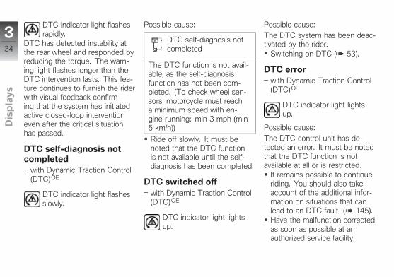
DTC indicator light flashesrapidly.
DTC has detected instability atthe rear wheel and responded byreducing the torque. The warn-ing light flashes longer than theDTC intervention lasts. This fea-ture continues to furnish the riderwith visual feedback confirm-ing that the system has initiatedactive closed-loop interventioneven after the critical situationhas passed.
DTC self-diagnosis notcompleted
with Dynamic Traction Control(DTC)OE
DTC indicator light flashesslowly.
Possible cause:
DTC self-diagnosis notcompleted
The DTC function is not avail-able, as the self-diagnosisfunction has not been com-pleted. (To check wheel sen-sors, motorcycle must reacha minimum speed with en-gine running: min 3 mph (min5 km/h))
Ride off slowly. It must benoted that the DTC functionis not available until the self-diagnosis has been completed.
DTC switched offwith Dynamic Traction Control(DTC)OE
DTC indicator light lightsup.
Possible cause:The DTC system has been deac-tivated by the rider.
Switching on DTC ( 53).
DTC errorwith Dynamic Traction Control(DTC) OE
DTC indicator light lightsup.
Possible cause:The DTC control unit has de-tected an error. It must be notedthat the DTC function is notavailable at all or is restricted.
It remains possible to continueriding. You should also takeaccount of the additional infor-mation on situations that canlead to an DTC fault ( 145).Have the malfunction correctedas soon as possible at anauthorized service facility,
334
z Dis
pla
ys

preferably an authorizedBMW Motorrad retailer.
DDC errorwith Dynamic Damping Control(DDC) OE
General warning light showsyellow.
DDC! is displayed.Possible cause:The DDC control unit has de-tected an error.
Have the malfunction correctedas soon as possible at anauthorized service facility,preferably an authorizedBMW Motorrad retailer.Motorcycle damping is in thiscondition very firm and riding israther uncomfortable - in par-ticular on rough roads.
Possible cause:The DDC control unit has de-tected an error.
Have the malfunction correctedas soon as possible at anauthorized service facility,preferably an authorizedBMW Motorrad retailer.Motorcycle damping is in thiscondition very firm and riding israther uncomfortable - in par-ticular on rough roads.
DWA battery charge levellow
with anti-theft alarm system(DWA)OE
General warning light showsyellow.
DWALO! is displayed.
NOTICE
This fault message is only shownfor a short time immediately fol-lowing the Pre-Ride-Check.
Possible cause:The anti-theft alarm battery nolonger has its full capacity. Theoperation of the anti-theft alarmsystem is only ensured for a lim-ited time with the motorcyclebattery disconnected.
Contact an authorized servicefacility, preferably an authorizedBMW Motorrad retailer.
DWA battery drainedwith anti-theft alarm system(DWA)OE
General warning light showsyellow.
DWA! is displayed.
335
z Dis
pla
ys

NOTICE
This fault message is only shownfor a short time immediately fol-lowing the Pre-Ride-Check.
Possible cause:The anti-theft alarm system bat-tery is completely discharged.Operation of the anti-theft alarmsystem is no longer ensuredwhen the motorcycle's batteryis disconnected.
Contact an authorized servicefacility, preferably an authorizedBMW Motorrad retailer.
Speed warningShiftpoint light flashes orremains on continuously
according to the selected setting.
SPEED! is displayed.
Possible cause:The preset maximum speed hasbeen exceeded.
Reduce speed.Enter a new maximum speed.
Launch Control not readywith Pro riding modesOE
Shiftpoint light lights up orflashes.
0L-CON! is indicated.Possible cause:The number of possible racingstarts with Launch Control hasbeen exceeded.
Let the clutch cool down.Race start with Launch Control( 128).
CAN open/short circuitGeneral warning light showsred.
NO CAN (Controller Area Net-work) is displayed.
Possible cause:A defect was determined in theController Area Network.
Contact an authorized servicefacility, preferably an authorizedBMW Motorrad retailer.
Encoding missingGeneral warning light showsyellow.
NO CODING is displayed.Possible cause:An encoding error was discov-ered.
The display goes out after 10seconds.Contact an authorized servicefacility, preferably an authorizedBMW Motorrad retailer.
Service date missedGeneral warning light showsyellow.
SERVICE! is indicated.
336
z Dis
pla
ys
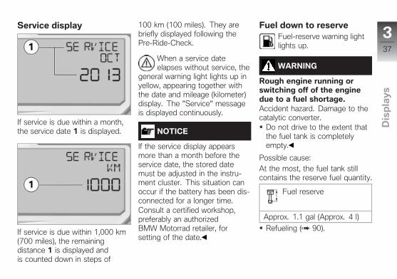
Service display
If service is due within a month,the service date 1 is displayed.
If service is due within 1,000 km(700 miles), the remainingdistance 1 is displayed andis counted down in steps of
100 km (100 miles). They arebriefly displayed following thePre-Ride-Check.
When a service dateelapses without service, the
general warning light lights up inyellow, appearing together withthe date and mileage (kilometer)display. The "Service" messageis displayed continuously.
NOTICE
If the service display appearsmore than a month before theservice date, the stored datemust be adjusted in the instru-ment cluster. This situation canoccur if the battery has been dis-connected for a longer time.Consult a certified workshop,preferably an authorizedBMW Motorrad retailer, forsetting of the date.
Fuel down to reserveFuel-reserve warning lightlights up.
WARNING
Rough engine running orswitching off of the enginedue to a fuel shortage.Accident hazard. Damage to thecatalytic converter.
Do not drive to the extent thatthe fuel tank is completelyempty.
Possible cause:At the most, the fuel tank stillcontains the reserve fuel quantity.
Fuel reserve
Approx. 1.1 gal (Approx. 4 l)
Refueling ( 90).
337
z Dis
pla
ys

Cruising range
The RANGE cruising range 1 in-dicates the distance that can stillbe driven with the remaining fuel.This distance is calculated basedon fuel quantity and average con-sumption.RANGE
If the motorcycle is standingon its side stand, the motor-cycle's inclined position willprevent the fuel level from be-ing registered accurately. Forthis reason travel range is onlycalculated with the side standretracted.
The travel range automaticallyappears in the multifunctiondisplay after the fuel reservelevel is reached.After refueling, the travel rangeis recalculated when the fuelquantity is greater than the fuelreserve.
NOTICE
The determined range isan approximate reading.BMW Motorrad thereforerecommends that you do nottry to use the full range beforerefueling.
338
z Dis
pla
ys

Operation
Steering and ignition lock . . . . . . . . . . . 40
Ignition . . . . . . . . . . . . . . . . . . . . . . . . . . . . . . 40
Electronic immobilizer. . . . . . . . . . . . . . . 41
Emergency on/off switch (killswitch) . . . . . . . . . . . . . . . . . . . . . . . . . . . . . . 41
Lights . . . . . . . . . . . . . . . . . . . . . . . . . . . . . . . 42
Hazard warning flashers . . . . . . . . . . . . . 43
Turn indicator . . . . . . . . . . . . . . . . . . . . . . . 43
Multifunction display . . . . . . . . . . . . . . . . 45
Alarm system . . . . . . . . . . . . . . . . . . . . . . . 48
Clock . . . . . . . . . . . . . . . . . . . . . . . . . . . . . . . 50
Anti-Lock Brake System . . . . . . . . . . . . 50
Automatic Stability Control . . . . . . . . . . 51
Dynamic Traction Control . . . . . . . . . . . 52
Riding mode . . . . . . . . . . . . . . . . . . . . . . . . 53
Cruise control . . . . . . . . . . . . . . . . . . . . . . . 57
Speed warning . . . . . . . . . . . . . . . . . . . . . . 59
Heated handlebar grips . . . . . . . . . . . . . 60
Rider and passenger seats . . . . . . . . . . 61
Helmet holder . . . . . . . . . . . . . . . . . . . . . . 63
Luggage straps . . . . . . . . . . . . . . . . . . . . . 64
439
z Op
era
tio
n

Steering and ignitionlockKeysYou are provided with 2 ignitionkeys.Should you lose your keys pleaserefer to the information regard-ing the electronic immobilizer(EWS) ( 41).A single key fits the steering andignition lock, the fuel filler capand the seat lock.
Locking handlebarsTurn handlebars to left.
Turn the ignition key to posi-tion 1 while moving the handle-bars somewhat.Ignition, lights and all electricalcircuits switched off.Handlebars locked.The ignition key can now beremoved.
IgnitionSwitch on ignition
Turn ignition key to position 1.Parking lights and all functioncircuits switched on.Engine can be started.Pre-Ride-Check is carried out.( 83)ABS self-diagnosis isperformed. ( 83)ASC self-diagnosis is per-formed. ( 84)with Dynamic Traction Control(DTC) OE
DTC self-diagnosis is per-formed. ( 85)
440
z Op
era
tio
n
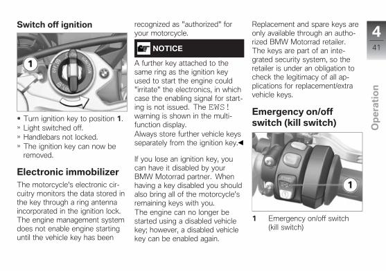
Switch off ignition
Turn ignition key to position 1.Light switched off.Handlebars not locked.The ignition key can now beremoved.
Electronic immobilizerThe motorcycle's electronic cir-cuitry monitors the data stored inthe key through a ring antennaincorporated in the ignition lock.The engine management systemdoes not enable engine startinguntil the vehicle key has been
recognized as "authorized" foryour motorcycle.
NOTICE
A further key attached to thesame ring as the ignition keyused to start the engine could"irritate" the electronics, in whichcase the enabling signal for start-ing is not issued. The EWS!warning is shown in the multi-function display.Always store further vehicle keysseparately from the ignition key.
If you lose an ignition key, youcan have it disabled by yourBMW Motorrad partner. Whenhaving a key disabled you shouldalso bring all of the motorcycle'sremaining keys with you.The engine can no longer bestarted using a disabled vehiclekey; however, a disabled vehiclekey can be enabled again.
Replacement and spare keys areonly available through an autho-rized BMW Motorrad retailer.The keys are part of an inte-grated security system, so theretailer is under an obligation tocheck the legitimacy of all ap-plications for replacement/extravehicle keys.
Emergency on/offswitch (kill switch)
1 Emergency on/off switch(kill switch)
441
z Op
era
tio
n

WARNING
Operation of the emergencyON/OFF switch when riding.Danger of falling due to blockingof rear wheel.
Do not operate the emergencyON/OFF switch when riding.
The engine can be switchedoff easily and quickly using theemergency on/off switch.
a Engine is switched offb Operating position
LightsParking lightsThe parking lights come on au-tomatically when the ignition isswitched on.
NOTICE
The parking lights are a strainon the battery. Do not leave theignition switched on longer thanabsolutely necessary.
Low-beam headlightThe headlights automaticallycome on in their low-beam modeas soon as you start the engine.
High-beam headlight andheadlight flasher
Start engine.
Press switch 1 toward front toswitch on high-beam headlight.Pull switch 1 toward rear toactuate headlight flasher.
Parking lightsSwitch off ignition.
442
z Op
era
tio
n

Immediately after switching offignition, push button 1 to leftand hold it until parking lightscome on.
NOTICE
The parking lights can only beswitched on within 10 secondsafter switching off the ignition.
Switch ignition on and then offagain to switch off parking light.
Hazard warningflashersSwitching on hazardwarning flashers
Switch on ignition.
NOTICE
The hazard warning flashersplace a strain on the battery.Do not use the hazard warningflashers for longer than absolutelynecessary.
Press button 1 to switch onhazard warning flashers.
Ignition can be switched off.Switch on ignition and pressbutton 1 again to switch offhazard warning flashers.
Turn indicatorOperating turn indicators
Switch on ignition.
Press button 1 to left to switchon left-side turn indicators.Press button 1 to right toswitch on right-side turnindicators.
443
z Op
era
tio
n

Press button 1 into center po-sition to switch off turn indica-tors.
NOTICE
The turn indicators automati-cally switch off when the defineddriving time and distance havebeen reached. The defined rid-ing time and distance can be setby an authorized BMW Motorradretailer.
444
z Op
era
tio
n

Multifunction displayOverview
— Solid line: briefly pressbutton.
‑ ‑ Dotted line: press and holdbutton.
1 OdometerStandard displaySelect displays in multi-function display ( 46)
2 LAP TIMER ( 99)3 LIMIT ( 59)
Factory setting for WARNSPEED ( 118)
4 RACE INFO ( 103)5 SETUP MENU ( 111)6 TRIP 1/TRIP 2
Reset tripmeter ( 47)7 Average consumption and
average speedReset average data( 47)
445
z Op
era
tio
n

Selecting displays inmultifunction display
Switch on ignition.All information required foroperation on public roads isprovided in the multifunctiondisplay.
Press TRIP 1 repeatedly untildesired value is displayed inarea 2.
The following values of theonboard computer can bedisplayed:
Total distance ODO (standarddisplay)
Cruising range RANGETrip distance 1 TRIP 1Trip distance 2 TRIP 2Average consumption AVG involume per distance or viceversaAverage speed AVG in dis-tance per hour
Selecting additionaldisplays
Briefly press SET 2 to obtainadditional displays.Briefly press TRIP 1 to returnto odometer ODO (standarddisplay).
Repeatedly press SET 2 untildesired display is selected.
The following displays are avail-able:
LAPTIMER: The lap timesand additional data can berecorded here and displayedagain in the RACE INFOmenu.RACE INFO: The stored in-formation from the LAPTI-MER can be displayed here.RACE INFO can only beopened with the motorcycleat a standstill.SETUP MENU: The behaviorof the instrument cluster canbe adjusted to the driver's pref-erences here. SETUP MENUcan only be opened with themotorcycle at a standstill.If LAPTIMER is shown, pressand hold SET 2 to open vari-ous displays for LAPTIMER.
446
z Op
era
tio
n

If LIMIT is shown, press andhold SET 2 to set current driv-ing speed as new limit.If RACE INFO ENTER orSETUP MENU ENTER isshown, press and hold SET 2to open the respective menu.
Resetting tripmeter
Switch on ignition.
Briefly press TRIP 1 repeatedlyuntil desired tripmeter is dis-played."TRIP 1" or "TRIP 2 " isindicated.
Press and hold TRIP 1 untiltripmeter has been reset.Trip mileage = 0.0
Resetting average data
Switch on ignition.
Briefly press TRIP 1 repeatedlyuntil average value to be resetis displayed.AVG is indicated.Press and hold TRIP 1 untilselected value has been reset.Average value = 0.0
447
z Op
era
tio
n

Alarm systemwith anti-theft alarm system(DWA)OE
ActivationSwitch on ignition ( 40).DWA Adjusting ( 49).Switch off ignition.If the DWA is activated, theDWA is automatically activatedafter the ignition is switchedoff.Activation takes approximately30 seconds to complete.Turn indicators are illuminatedtwice.Confirmation tone soundstwice (if programmed).DWA is armed.
AlarmThe alarm can be set off by:
motion sensoran attempt to use an unau-thorized key to switch on theignitiondisconnecting the alarm systemfrom the motorcycle battery(alarm system battery takesover the power supply - alarmtone only, no illumination of theturn indicators).
All functions are sustained evenif the internal battery of the anti-theft alarm system is completelydrained; the only difference isthat an alarm cannot be triggeredif the system is disconnectedfrom the motorcycle's battery.
An alarm lasts for approximately26 seconds. During the alarm,an alarm tone sounds and theturn indicators flash. The alarmtone type can be adjusted byan authorized BMW Motorradretailer.
If an alarm was triggered whilethe motorcycle was unattended,the rider is notified accordinglyby an alarm tone sounding oncewhen the ignition is switched on.The alarm system LED then in-dicates the reason for the alarmsignal for one minute.The meanings of the flash codesare as follows:
1 flash: Motion sensor 12 flashes: Motion sensor 23 flashes: Ignition switched onwith unauthorized key4 flashes: Alarm system is dis-connected from the motorcyclebattery5 flashes: Motion sensor 3
DeactivationEmergency on/off switch (killswitch) in normal operating po-sition.Switch on ignition.Turn indicators light up once.
448
z Op
era
tio
n

Confirmation tone sounds once(if programmed).DWA is now switched off.
DWA AdjustingSwitch on ignition ( 40).
Briefly press SET 2 repeat-edly until SETUP MENU EN-TER 3 is displayed.
NOTICE
If the display has been scrolledtoo far, briefly press SET 2 re-peatedly until the menu returns
to the start and finally to the de-sired display.
Press and hold SET 2 to openthe menu.
Briefly press SET 2 repeatedlyuntil SETUP EQUIPMENTENTER 4 is displayed.
NOTICE
If the display has been scrolledtoo far, briefly press TRIP 1 toscroll back.
Press and hold SET 2 to openthe menu.
Parameter DWA AUTO 5 andits current value 6 are dis-played.
Press and hold SET 2 to editthe set value 6.The value 6 flashes.Briefly press TRIP 1 or SET 2to change the value.
The following settings are avail-able:DWA AUTO ON: DWA is acti-vated respectively is activatedautomatically when the ignitionis switched off.
449
z Op
era
tio
n

DWA AUTO OFF: DWA isdeactivated.Press and hold SET 2 to savethe set value.The value 6 no longer flashes.The clock is now set.Press and hold TRIP 1 to can-cel the adjustment procedure.Adjustment canceled.ODO is indicated
ClockSetting clock
Switch on ignition.
Briefly press SET 2 repeatedlyuntil SETUP MENU ENTERis displayed.Press and hold SET 2.The SETUP MENU isopened.Briefly press SET 2 repeatedlyuntil SETUP EQUIPMENTENTER is displayed.Press and hold SET 2.The SETUP EQUIPMENTmenu is opened.Briefly press SET 2 repeatedlyuntil SETUP EQIP:CLOCKTIME is displayed.Press and hold SET 2.
Minutes 4 flash.Briefly press TRIP 1 to in-crease minutes.Briefly press TRIP 2 to de-crease minutes.When the minutes have beenset as desired, press and holdSET 2.Hours 3 flash.Briefly press TRIP 1 to in-crease hours.Briefly press TRIP 2 to de-crease hours.When the hours have beenset as desired, press and holdSET 2.The hours no longer flash.The clock is now set.
Anti-Lock BrakeSystemDeactivate ABS
Switch on the ignition.
450
z Op
era
tio
n

NOTICE
The BMW Motorrad Race ABSfunction can also be deactivatedwhile driving.
Press and hold the 1 buttonuntil first the ASC / DTC indi-cator light 3 and then the ABSindicator and warning light 2change their display behavior.The ASC/DTC setting remainsunchanged.
ABS indicator light lightsup.
Release button 1 within twoseconds.
ABS indicator light contin-ues to be lit up.
ABS is deactivated.
Activating ABS
Press and hold the 1 buttonuntil first the ASC / DTC indi-cator light 3 and then the ABSindicator and warning light 2change their display behavior.The ASC/DTC setting remainsunchanged.
ABS indicator light goesout, and starts to flash if
self-diagnosis has not been com-pleted.
If the coding plug for theSLICK/USER riding mode isnot installed, the ignition canalso be switched off and thenon again as an alternative.
If the ABS indicator lightlights up after switch-
ing the ignition off and on andthen continuing to ride abovethe minimum speed, an ABSfault has occurred.
min 6 mph (min 10 km/h)
Automatic StabilityControlDeactivating ASC
Switch on the ignition.
451
z Op
era
tio
n
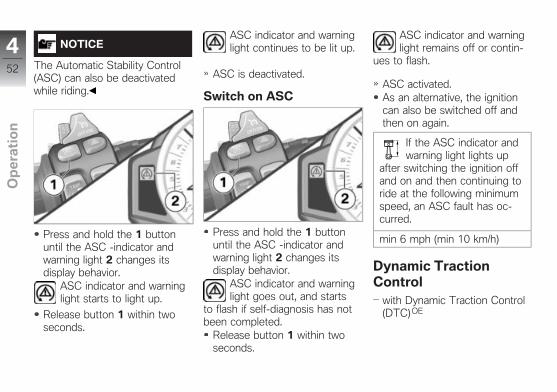
NOTICE
The Automatic Stability Control(ASC) can also be deactivatedwhile riding.
Press and hold the 1 buttonuntil the ASC -indicator andwarning light 2 changes itsdisplay behavior.
ASC indicator and warninglight starts to light up.
Release button 1 within twoseconds.
ASC indicator and warninglight continues to be lit up.
ASC is deactivated.
Switch on ASC
Press and hold the 1 buttonuntil the ASC -indicator andwarning light 2 changes itsdisplay behavior.
ASC indicator and warninglight goes out, and starts
to flash if self-diagnosis has notbeen completed.
Release button 1 within twoseconds.
ASC indicator and warninglight remains off or contin-
ues to flash.
ASC activated.As an alternative, the ignitioncan also be switched off andthen on again.
If the ASC indicator andwarning light lights up
after switching the ignition offand on and then continuing toride at the following minimumspeed, an ASC fault has oc-curred.
min 6 mph (min 10 km/h)
Dynamic TractionControl
with Dynamic Traction Control(DTC) OE
452
z Op
era
tio
n

Deactivating DTCSwitch on the ignition.
NOTICE
The Dynamic Traction Control(DTC) can also be deactivatedwhile riding.
Press and hold the 1 buttonuntil the DTC --indicator light 2changes its display behavior.
DTC indicator light starts tolight up.
Release button 1 within twoseconds.
DTC indicator light contin-ues to be lit up.
DTC is deactivated.
Switching on DTC
Press and hold the 1 buttonuntil the DTC --indicator light 2changes its display behavior.
DTC indicator light goesout, and if self-diagnosis
has not been completed, it be-gins to flash.
Release button 1 within twoseconds.
DTC indicator light remainsoff or continues to flash.
DTC activated.If the coding plug is not in-stalled, the ignition can also beswitched off and then on againas an alternative.
If the DTC indicator lightlights up after switch-
ing the ignition off and on andthen continuing to ride at thefollowing minimum speed, aDTC fault has occurred.
min 6 mph (min 10 km/h)
Riding modeUse of the riding modesBMW Motorrad has developed 5riding scenarios for your motor-cycle from which you can selectthe one matching your situation:
453
z Op
era
tio
n

Riding on wet roads.Sporty riding on dry roads.Riding on racetracks with se-ries tires.
with Dynamic Traction Control(DTC)OE
Riding on racetracks with se-ries tires.Riding on racetracks with rac-ing tires while taking settingsby driver into account.
For each of those 5 scenarios,the optimum balance betweenengine torque, throttle response,ABS control and ASC or DTCcontrol for the situation con-cerned is provided.
with Dynamic Damping Control(DDC) OE
The suspension settings is ad-justed to the selected scenarioas well.
Setting riding modeSwitch on ignition ( 40).
Press button 1.
NOTICE
Details on the selectable drivingmodes are provided in the chap-ter "Technology in Detail".
The selection arrow 2 and theselectable riding modes 3 aredisplayed. The last active ridingmode flashes.
454
z Op
era
tio
n

with Pro riding modesOE
With the coding plug installed,the riding modes SLICK 4 andUSER 5 are also offered.
WARNING
Activating the SLICK modeoutside the racetrack orwithout racing tires.Risk of accident caused by lowtire grip.
Only activate SLICK mode onracetracks and with racing tiresfitted.
Press 1 button repeatedly untilselection arrow 2 points to de-sired riding mode.When the vehicle is stationary,the selected riding mode is ac-tivated after approx. 2 seconds.
Selection arrow 2 and inactiveriding modes are hidden.The new riding mode is acti-vated during operation underthe following conditions:The throttle grip is in the neu-tral position.The brake lever is not beingoperated.
The following riding modes canbe selected:RAIN: When riding on wetroads.SPORT: For sporty riding ondry roads.RACE: For riding on racetrackswith series tires.
The following riding modes canalso be selected:with Pro riding modesOE
SLICK: For riding on race-tracks with racing tires (onlywith coding plug installed).
455
z Op
era
tio
n

with Pro riding modesOE
USER: Riders can combinethe settings from all availablefunctions (ENGINE, ABS, DTCand DDC) in any way theywish, according to their pref-erences or current prevailingconditions. A technical un-derstanding of the settingsis assumed (only with codingplug installed, see the chapter"Technology in detail").
The riding mode selected andits associated engine-charac-teristic, ABS DTC and DDCsettings are retained even afterthe ignition has been switchedoff.When selecting SLICK rid-ing mode: Observe restrictedABS control intervention at rearwheel (see chapter "Technol-ogy in detail").The values set in the SETUPUSER-MODE are not contin-
ually displayed, but instead onlyafter the following events for alimited time:After every pre-ride check withUSER riding mode active.After changing to USER ridingmode.When 1 (MODE) button ispressed in USER riding modewithout changing riding mode.
Install coding plugwith Pro riding modesOE
WARNING
Increased engine perfor-mance in all riding modesby inserting the coding plugon motorcycles with powerreduction.Accident hazard
Familiarize yourself with themore performance-orientedresponse.
Do not use the encoding plugon public roads.
Switch off ignition ( 41).Removing rider`s seat ( 63).
ATTENTION
Penetration of dirt and mois-ture in the open connector.Malfunctions
After removing the encodingplug, refit the cover cap.
Remove cap 1 of connector.
456
z Op
era
tio
n

To do so, press in locking de-vice 2 and pull off cap.Insert coding plug.Switch on the ignition.For safety reasons, after thecoding plug is connected, theRAIN riding mode is automat-ically activated.Set riding mode ( 54).The set riding mode remainsactive even after the ignition isswitched off.Installing driver's seat ( 63).Remove license-plate carrier( 132).
Cruise controlwith cruise controlOE
Switching on cruisecontrol
Push switch 1 to right.Button 2 is unlocked.
Storing speed
Briefly press button 1 forward.
Adjustment range forcruise control
19...130 mph (30...210 km/h)
Indicator light for cruise-control system lights up.
The motorcycle maintains yourcurrent cruising speed and thesetting is saved.
457
z Op
era
tio
n

Acceleration
Briefly press button 1 forward.
Increase speed
Speed is increased each timebutton is pressed.
1 mph (1 km/h)
Press button 1 forward andhold.The motorcycle acceleratessteplessly.If the button 1 is no longerpressed, the speed achievedis maintained and saved.
Decreasing speed
Briefly press button 1 back-ward.
Decreasing the speed
Speed is decreased each timebutton is pressed.
1 mph (1 km/h)
Press button 1 back and hold.The motorcycle deceleratessteplessly.If the button 1 is no longerpressed, the speed achievedis maintained and saved.
Deactivating cruisecontrol
Actuate brakes, clutch or throt-tle grip (take back throttle be-yond back position) to deacti-vate cruise-control system.
NOTICE
When changing gear using thePro Gear-shift Assistance func-tion, the cruise-control systemis automatically deactivated forsafety reasons.
NOTICE
With ASC and DTC interventions,the cruise control is automaticallydeactivated for safety reasons.
Cruise control indicator lightgoes out.
458
z Op
era
tio
n

Resuming former cruisingspeed
Briefly push button 1 back toreturn to the speed saved be-forehand.
NOTICE
Opening the throttle does notdeactivate the cruise-control sys-tem. If you release the throttlegrip, the motorcycle will decel-erate only to the cruising speedsaved in memory, even thoughyou might have intended slowingto a lower speed.
Indicator light for cruise-control system lights up.
Switching off cruisecontrol
Push switch 1 to left.The system is deactivated.Button 2 is locked.
Speed warningSetting speed warning
If necessary, activate speedwarning in SETUP EQUIP-MENT submenu. See chapter"On the racetrack":
Speed warning ( 118)
Briefly press SET 2 repeat-edly until LIMIT is shown indisplay.
Either the current preset speedor OFF appears in the display.
459
z Op
era
tio
n

To set current speed as newlimit: press and hold SET 2.The current speed is displayedTo increase set speed: brieflypress TRIP 1.Each time you press the buttonthe speed increases by 3 mph(5 km/h).
When the preset speed is ex-ceeded, the shiftpoint light 1 re-sponds by lighting up or flashingat the preset frequency and thewarning 2 appears in the display.
To deactivate the speed warn-ing: Press and hold TRIP 1 un-til OFF appears in the display.
Heated handlebar gripswith heated handlebar grips OE
Operating heated gripsStart engine.
NOTICE
The heated grips option can onlybe activated when the engine isrunning.
460
z Op
era
tio
n

NOTICE
The increase in powerconsumption caused by theheated grips can drain thebattery if you are riding at lowengine speeds. If the battery isinadequately charged, the heatedgrips are switched off to ensurestarting capability.
Press button 1 repeatedly untildesired heating level is dis-played in multifunction display.
The handlebar grips can beheated at two different levels.The second stage 2 is intendedfor rapid heating of the grips.Once they are warm you shouldswitch back to the first stage.
Second step: 100 % heat-ing capacity
First step: 50 % heatingcapacity
If no further changes are madethe selected heating level isadopted as the setting.
Rider and passengerseatsRemoving hump cover
with passenger seat cover OE
Park motorcycle, ensuring thatsupport surface is firm andlevel.
Unlock lock 2 in hump cover 1using ignition key.Lift hump cover at rear, thenremove by pulling back andupward.
461
z Op
era
tio
n

Installing hump coverwith passenger seat cover OE
Mount hump cover inmounts 1 on left and right.
Press the hump cover forwardslightly then fold it down.
Lock lock with ignition key.
Removing passenger seatPark motorcycle, ensuring thatsupport surface is firm andlevel.
Unlock seat lock 1 with vehicleignition key.Lift passenger seat at rear,then remove by pulling backand upward.Remove ignition key and laypassenger seat on a clean sur-face with upholstered side onbottom.
Install the passenger seat
Mount passenger seat inmounts 1 on left and right.
Press the rear seat forwardslightly then fold it down.
462
z Op
era
tio
n

Lock seat lock with ignitionkey.
Removing rider`s seat
Press cover of driver's seatabove screws 1 forward some-what and hold in place.Remove screws.Push the rider`s seat forward,lift it at the rear and remove it.When doing so, make sure thatthe paneling is not damaged bythe screws.Lay the rider`s seat on a cleansurface with the upholsteredside down.
Installing driver's seat
Mount rider`s seat in mount 2,then position over screw sock-ets 3. When doing so, makesure that the paneling is notdamaged by the screws.
Press cover of driver's seatover screw sockets towardfront somewhat and hold inplace.Install screws 1.
Helmet holderSecuring helmet onmotorcycle
Remove passenger seat( 62).Turn over passenger seat.
463
z Op
era
tio
n

ATTENTION
Incorrect positioning of thehelmet lock.Fairing scratched.
When hooking on the helmet,watch the position of the hel-met lock.
Secure helmet on helmetholder 1 using a steel cable.Install the passenger seat( 62).Set down helmet on driver'sseat.
Luggage strapsSecuring luggage onmotorcycle
Remove passenger seat( 62).Turn over passenger seat.
Remove luggage loops 1 fromholders and lay to outside.Install the passenger seat( 62).
Use luggage loops 1, e.g. inconjunction with passengerfootrests, to lash luggage ontopassenger seat. When doingso, make sure that the rear trimis not damaged.
464
z Op
era
tio
n

Setting
Mirrors . . . . . . . . . . . . . . . . . . . . . . . . . . . . . . 66
Headlight . . . . . . . . . . . . . . . . . . . . . . . . . . . 66
Brakes . . . . . . . . . . . . . . . . . . . . . . . . . . . . . . 66
Steering . . . . . . . . . . . . . . . . . . . . . . . . . . . . 67
Spring preload . . . . . . . . . . . . . . . . . . . . . . 67
Damping . . . . . . . . . . . . . . . . . . . . . . . . . . . . 72
DDC . . . . . . . . . . . . . . . . . . . . . . . . . . . . . . . . 75
565
z Se
ttin
g

MirrorsAdjusting mirrors
Move mirror to the desired po-sition by turning it.
HeadlightAdjusting headlight forRHD/LHD trafficThis motorcycle's headlight fea-tures a symmetrical low beam.No special adjustments or proce-dures are required prior to oper-ating the motorcycle in a coun-try where traffic travels on theside of the road opposite to that
of your home country (left-handdrive to right-hand drive or viceversa).
Headlight range andspring preloadThe headlight range generallyremains constant due to the ad-justment of the spring preload tothe loading state.
NOTICE
If there are doubts as to the cor-rect headlight range, have theadjustment checked by a spe-cialized workshop, preferably byan authorized BMW Motorradretailer.
BrakesAdjusting brake lever
WARNING
Modified position of thebrake-fluid reservoir.
Air in the brake system.Do not twist the handlebar fit-ting or the handlebars.
WARNING
Adjusting the brake leverwhile driving.Accident hazard
Only adjust the brake leverwhen the motorcycle isstationary.
Rotate the adjusting screw 1into the desired position byapplying gentle pressure fromthe rear.
566
z Se
ttin
g

NOTICE
The adjusting screw can beturned more easily if you pushthe brake lever forward whendoing so.
Adjustment options:From position 1: Largest dis-tance between handlebar gripand brake leverTo position 6: Smallest dis-tance between handlebar gripand brake lever
SteeringAdjusting steering damper
WARNING
Adjusting the steeringdamper while riding.Accident hazard
Never adjust the steeringdamper except while themotorcycle is stationary.
Turn adjustment screw 1 in di-rection A to increase dampingforce.Turn the screw 1 in direction Bto reduce damping force.
Basic steering damperadjustment setting
Opens at 8 clicks (starting atfully closed) (Highway opera-tion)
Opens at 5 clicks (starting atfully closed) (Racetrack)
Spring preloadSettingThe spring preload on the frontwheel must be adapted to theweight of the rider. Higherweight requires a higher springpreload, lower weight requires alower spring preload.It is essential to set the springpreload to suit the load carried bythe motorcycle. Increase springpreload when the vehicle is heav-ily loaded and reduce springpreload accordingly when thevehicle is lightly loaded.
567
z Se
ttin
g

Adjusting spring preloadon front wheel
without Dynamic DampingControl (DDC) OE
Park motorcycle, ensuring thatsupport surface is firm andlevel.Make sure there is no load onthe motorcycle, removing anycargo or luggage.
Hold motorcycle in a verti-cal position and measure dis-tance D between lower edge 1of immersion tube and frontaxle 2.
Load motorcycle with driver.With the assistance of a helper,measure distance D betweenpoints 1 and 2 again and cal-culate difference (spring deflec-tion) between the measuredvalues.
Adjustment of springpreload dependent on
loading
Compressing front wheel
0.4...0.6 in (10...15 mm) (Withrider 187 lbs (85 kg))
WARNING
Uncoordinated settings ofspring preload and springstrut damping.Poorer handling.
Adjust damping characteristicto changed spring preload.
To decrease spring deflection(increase spring preload), turnadjusting screws 3 with tool ofonboard tool kit in direction A.To increase spring deflection(decrease spring preload), turnadjusting screws 3 with tool ofonboard tool kit in direction B.
568
z Se
ttin
g

Ensure that settings on left andright sides are identical.
Adjusting spring preloadon front wheel
with Dynamic Damping Control(DDC) OE
Park motorcycle, ensuring thatsupport surface is firm andlevel.
Hold motorcycle in vertical po-sition, preferably with help ofa second person (not the sidestand).
Measure distance D betweenlower edge 1 of immersiontube and front axle 2.Load motorcycle with driver.Measure distance D betweenpoints 1 and 2 with assistanceof a 2nd person.Calculate spring deflection asdifference between measuredvalues.
Adjustment of springpreload dependent on
loading
Compressing front wheel
0.4...0.6 in (10...15 mm) (Withrider 187 lbs (85 kg))
WARNING
Uncoordinated settings ofspring preload and springstrut damping.Poorer handling.
Adjust damping characteristicto changed spring preload.
To decrease spring deflection(increase spring preload), turnadjusting screw 3 with tool ofonboard tool kit in direction A.To increase spring deflection(decrease spring preload), turnadjusting screw 3 with tool ofonboard tool kit in direction B.
569
z Se
ttin
g

Adjusting spring preloadat rear wheel
without Dynamic DampingControl (DDC) OE
Park motorcycle, ensuring thatsupport surface is firm andlevel.Make sure there is no load onthe motorcycle, removing anycargo or luggage.
Loosen screw 1 with tool fromonboard tool kit.
Hold motorcycle in vertical po-sition (not with side stand) andmeasure distance D betweenlower edge 1 of license-platecarrier and screw 2 of chainguard.Load motorcycle with driver.With the assistance of a helper,measure distance D betweenpoints 1 and 2 again and cal-culate difference (spring deflec-tion) between the measuredvalues.
Adjustment of springpreload dependent on
loading
Spring deflection of rear wheel
0.31...0.47 in (8...12 mm) (Withrider 187 lbs (85 kg))
WARNING
Uncoordinated settings ofspring preload and springstrut damping.Poorer handling.
Adjust damping characteristicto changed spring preload.
570
z Se
ttin
g

To increase the spring deflec-tion (reduce spring preload),use the tool from the onboardtool kit to turn the adjustmentring 2 in direction B.To decrease the spring deflec-tion (increase spring preload),use the tool from the onboardtool kit to turn the adjustmentring 2 in direction A.Tighten screw 1 to specifiedtorque.
Screw on adjustmentring
2 lb/ft (3 Nm)
Adjusting spring preloadat rear wheel
with Dynamic Damping Control(DDC) OE
Park motorcycle, ensuring thatsupport surface is firm andlevel.
Switch on ignition.Start engine to avoid discharg-ing battery.
NOTICE
Settings on the DDC systemare only possible with the igni-tion switched on, as the elec-tric valves are only active in thiscase.
Hold motorcycle in vertical po-sition, preferably with the helpof a second person (not theside stand).Measure distance D betweenlower edge 1 of license-plate
carrier and screw 2 of chainguard.Load motorcycle with driver.With the assistance of a helper,measure distance D betweenpoints 1 and 2 again and cal-culate difference (spring deflec-tion) between the measuredvalues.
Adjustment of springpreload dependent on
loading
Spring deflection of rear wheel
0.31...0.47 in (8...12 mm) (Withrider 187 lbs (85 kg))
571
z Se
ttin
g

To decrease the spring deflec-tion (increase spring preload),use the tool from the onboardtool kit to turn the adjustmentring 1 in direction A.To increase the spring deflec-tion (reduce spring preload),use the tool from the onboardtool kit to turn the adjustmentring 1 in direction B.
DampingSettingDamping must be adjusted to theroad conditions and the springpreload.
A rough road surface requiressofter damping than a smoothroad surface.An increase in spring preloadrequires firmer damping, a re-duction in spring preload re-quires softer damping.
Adjusting compressiondamping on front wheel
without Dynamic DampingControl (DDC) OE
Adjust compression dampingwith adjusting screw 1 and redscale on left-hand fork leg.
To increase damping: turn ad-justing screw with tool fromonboard tool kit so that mark-
572
z Se
ttin
g

ing 2 points to higher figure onscale.To decrease damping: turnadjusting screw with tool fromonboard tool kit so that mark-ing 2 points to lower figure onscale.
Compression stage, ba-sic setting, front
Position 2 (comfortable settingwith rider 187 lbs (85 kg))
Position 4 (standard settingwith rider 187 lbs (85 kg))
Position 8 (sport-oriented set-ting with rider 187 lbs (85 kg))
Rebound-stage dampingon front wheel
without Dynamic DampingControl (DDC) OE
Adjust rebound-stage damp-ing with adjusting screw 1 andyellow scale on right-hand forkleg.
To increase damping: turn ad-justing screw with tool fromonboard tool kit so that mark-
ing 2 points to a higher scalefigure.To decrease damping: turnadjusting screw with tool fromonboard tool kit so that mark-ing 2 points to a lower figureon the scale.
Rebound stage, basicsetting, front
Position 2 (comfortable settingwith rider 187 lbs (85 kg))
Position 4 (standard settingwith rider 187 lbs (85 kg))
Position 7 (sport-oriented set-ting with rider 187 lbs (85 kg))
Factory settings at frontwheel
Use following specification datato adjust to factory settings.
573
z Se
ttin
g

Factory settings forjounce/rebound at front
Position 4
Adjusting compressiondamping (jounce) at rearwheel
without Dynamic DampingControl (DDC) OE
Park motorcycle, ensuring thatsupport surface is firm andlevel.
Adjust compression dampingwith adjusting screw 1 and redscale.
To increase damping: turn ad-justing screw with tool fromonboard tool kit so that mark-
ing 2 points to a higher scalefigure.To decrease damping: turnadjusting screw with tool fromonboard tool kit so that mark-ing 2 points to a lower figureon the scale.
Compression stage, ba-sic setting, rear
Position 2 (comfortable settingwith rider 187 lbs (85 kg))
Position 4 (standard settingwith rider 187 lbs (85 kg))
Position 9 (sport-oriented set-ting with rider 187 lbs (85 kg))
Adjusting rebound-stagedamping at rear wheel
without Dynamic DampingControl (DDC) OE
Park motorcycle, ensuring thatsupport surface is firm andlevel.
574
z Se
ttin
g

Adjust rebound-stage dampingwith adjusting screw 1 and yel-low scale.
To increase damping: turn ad-justing screw with tool fromonboard tool kit so that mark-
ing 2 points to a higher scalefigure.To decrease damping: turnadjusting screw with tool fromonboard tool kit so that mark-ing 2 points to a lower figureon the scale.
Rebound stage, basicsetting, rear
Position 2 (comfortable settingwith rider 187 lbs (85 kg))
Position 4 (standard settingwith rider 187 lbs (85 kg))
Position 7 (sport-oriented set-ting with rider 187 lbs (85 kg))
Factory settings at rearwheel
Use the following specificationdata to adjust to factory set-tings.
Factory settings forjounce/rebound at rear
Position 4
DDCSettingDamping must be adjusted to theroad conditions and the springpreload.
A rough road surface requiressofter damping than a smoothroad surface.An increase in spring preloadrequires firmer damping, a re-duction in spring preload re-quires softer damping.
Adjusting damping on rearwheel
with Dynamic Damping Control(DDC) OE
Adjustment is carried out in theSETUP DDC-SYS submenu.
575
z Se
ttin
g

Park motorcycle, ensuring thatsupport surface is firm andlevel.Select submenu ( 113).The SETUP DDC-SYS sub-menu has been selected.
To adjust the rebound at therear wheel, briefly press TRIP 1or SET 2 repeatedly until inline 3 REAR and in line 4REB: (Rebound) is displayed.Press and hold SET 2.The value next to REB:flashes.
Adjust damping as desired withTRIP 1 and SET 2.+1 … +7: Damping increasein a maximum of seven steps(harder).-1 … -7: Damping decreasein a maximum of seven steps(softer).0: Factory settingPress and hold SET 2 until dis-played value no longer flashes.The value for the current ridingmode is saved.To adjust the rebound at therear wheel, briefly press TRIP 1or SET 2 repeatedly until inline 3 REAR and in line 4COM: (Compression) is dis-played.Press and hold SET 2.The value next to COM:flashes.Adjust damping as desired withTRIP 1 and SET 2.Press and hold SET 2 until dis-played value no longer flashes.
NOTICE
Damping is adjusted and savedseparately for all riding modes inthe SETUP DDC-SYS sub-menu.Damping is also adjusted andsaved separately for the DDCmodes DDC SPORT, DDCRACE and DDC SLICK pos-sible in the USER riding mode.
The value for the current ridingmode is saved.
Adjusting damping onfront wheel
with Dynamic Damping Control(DDC) OE
Adjustment is carried out in theSETUP DDC-SYS submenu.
Park motorcycle, ensuring thatsupport surface is firm andlevel.Select submenu ( 113).
576
z Se
ttin
g

The SETUP DDC-SYS sub-menu has been selected.
FRONT DMP Adjusting
The adjust damping, brieflypress TRIP 1 or SET 2 repeat-edly until in line 3 FRONT isdisplayed and in line 4 DMP:(Damping).
NOTICE
The display differs when a springtravel sensor for the front forks isused (racing accessory).
Press and hold SET 2.
The value next to DMP:flashes.Adjust damping as desired withTRIP 1 and SET 2.+1 … +7: Damping increasein a maximum of seven steps(harder).-1 … -7: Damping decreasein a maximum of seven steps(softer).0: Factory settingPress and hold SET 2 until dis-played value no longer flashes.The value for the current ridingmode is saved.
Performing zero positionalignment
with Dynamic Damping Control(DDC) OE
Adjustment is carried out in theSETUP DDC-SYS submenu.
Place motorcycle on side standor a suitable auxiliary stand.
During the alignment, do not siton the motorcycle and removeany cargo or luggage.Select submenu ( 113).The SETUP DDC-SYS sub-menu has been selected.
To set the zero position, brieflypress TRIP 1 or SET 2 repeat-edly until CALIB (Calibration)is displayed in line 4.Press and hold SET 2 untilCALIB begins to flash.CALIB flashes.Zero position is calibrated.
577
z Se
ttin
g

If the zero position alignment hasbeen carried out successfully,CALIB DONE is displayed inline 3 and 4.If CALIB FAIL is displayed:
Repeat alignment.If CALIB DONE is notdisplayed after repeatedcalibration, please contact aBMW authorized workshop,preferably an authorizedBMW Motorrad retailer.
578
z Se
ttin
g

Riding
Safety instructions . . . . . . . . . . . . . . . . . . 80
Observe checklist . . . . . . . . . . . . . . . . . . . 81
Starting . . . . . . . . . . . . . . . . . . . . . . . . . . . . . 82
Breaking in . . . . . . . . . . . . . . . . . . . . . . . . . . 85
Shifting gears . . . . . . . . . . . . . . . . . . . . . . . 87
Brakes . . . . . . . . . . . . . . . . . . . . . . . . . . . . . . 88
Parking your motorcycle . . . . . . . . . . . . 89
Refueling . . . . . . . . . . . . . . . . . . . . . . . . . . . 90
Secure motorcycle for transport . . . . 92
679
z Rid
ing

Safety instructionsRider's EquipmentDo not ride without the correctclothing. Always wear:
HelmetRider's suitGlovesBoots
This applies even to shortjourneys, and to every seasonof the year. Your authorizedBMW Motorrad retailer will behappy to advise you and hasthe correct clothing for everypurpose.
Loading
WARNING
Reduced riding stabilitycaused by overloading anduneven loading.Accident hazard
Do not exceed the grossweight limit and observe theloading information.
Adjust spring preload anddamping rate for the currentgross vehicle weight.
SpeedIf you ride at high speed, alwaysbear in mind that various bound-ary conditions can adversely af-fect the handling of your motor-cycle:
Settings of spring-strut andshock absorber systemImbalanced loadLoose clothingInsufficient tire inflation pres-surePoor tire treadEtc.
Risk of poisoningExhaust fumes contain carbonmonoxide, which is colorless andodorless but highly toxic.
WARNING
Harmful exhaust gas.Danger of suffocation
Do not inhale exhaust fumes.Do not run the engine inclosed rooms.
Burn hazard
CAUTION
Engine and exhaust systembecome very hot when themotorcycle is in use.Burn hazard
After parking the vehicle, makesure that no persons or objectscome into contact with the en-gine and exhaust system.
680
z Rid
ing

Catalytic converterIf misfiring causes unburned fuelto enter the catalytic converter,there is a danger of overheatingand damage.For this reason, observe the fol-lowing points:
Do not run the fuel tank dryDo not run the engine with thespark-plug cap removedStop engine immediately if itmisfiresUse unleaded fuel onlyComply with all specified main-tenance intervals
ATTENTION
Unburned fuel in the catalyticconverter.Damage to the catalytic con-verter.
Note the points listed forprotection of the catalyticconverter.
Danger of overheating
ATTENTION
Engine idling for a lengthyperiod while at a standstill.Overheating caused by insuffi-cient cooling. In extreme cases,the motorcycle could catch fire.
Do not allow the engine to idleunnecessarily.After starting, ride offimmediately.
Modifications
ATTENTION
Modifications to the motor-cycle (e.g. engine controlunit, throttle valves, clutch).Damage to the affected parts,failure of safety-relevant func-tions. Damage caused by modifi-cations invalidates the warranty.
Do not make anymodifications.
Observe checklistUse the following checklist tocheck your motorcycle at regu-lar intervals.
Before every journey:Function of the brake systemFunction of the lighting andsignal systemCheck clutch function ( 165).Checking tire tread depth( 168).Firm seating of cases and lug-gage
At every third refuelling stop:without Dynamic DampingControl (DDC) OE
Adjusting spring preload at rearwheel ( 70).Adjusting compressiondamping (jounce) at rear wheel( 74).
681
z Rid
ing

with Dynamic Damping Control(DDC) OE
Adjusting spring preload at rearwheel ( 71).
with Dynamic Damping Control(DDC) OE
Adjusting damping on rearwheel ( 75).Check engine oil level ( 159).Check front brake pad thick-ness ( 161).Check rear brake pad thickness( 162).Check front brake fluid level( 163).Checking rear brake fluid level( 164).Checking coolant level( 166).Lubricate chain ( 189).Checking chain tension( 189).
StartingStarting engine
Switch on ignition.Pre-Ride-Check is carried out.( 83)ABS self-diagnosis isperformed. ( 83)ASC self-diagnosis is per-formed. ( 84)Engage neutral, or pull backclutch lever if a gear is en-gaged.
NOTICE
You cannot start the motorcyclewith the side stand extended anda gear engaged. The engine willswitch itself off if it is started withthe transmission in neutral andthen a gear is engaged beforeretracting the side stand.
For cold starts and at low am-bient temperatures: pull lever
to disengage clutch and twistthrottle grip slightly.
Press starter button 1.
NOTICE
The starting attempt is automati-cally interrupted if battery voltageis too low. Recharge the batterybefore you attempt to start theengine again, or use jumper ca-bles and a donor battery to start.More detailed information canbe found in the "Maintenance"chapter under "Jump-starting".
Engine starts.
682
z Rid
ing

Consult the troubleshootingchart if the engine refuses tostart. ( 200)
Pre-Ride-CheckAfter switching off the ignition,the instrument cluster carries outa test on the warning lights andthe engine speed display (thePre-Ride-Check). Starting theengine before the test routine iscompleted will cancel the remain-der of the routine.
Phase 1
The indicator and warning lights1 light up and the universal warn-ing light 3 lights up in yellow.The tachometer needle 2 isrun up to the maximum enginespeed.All segments are shown in thedisplay.
Phase 2The universal warning lightchanges from yellow to red.
Phase 3The tachometer needle dropsback to zero.
The indicator and warning lightsgo out.The display reverts to the stan-dard format. The odometer isdisplayed.
Should one of the warning lightsfail to appear:
WARNING
Defective warning lights.Lack of display of malfunctions.
Watch all warning and indicatorlights on the display.
Have the malfunction correctedas soon as possible at anauthorized service facility,preferably an authorizedBMW Motorrad Retailer.
ABS self-diagnosisThe readiness for operation ofthe BMW Motorrad Race ABSis checked by the self-diagnosis.The self-diagnosis routine runsautomatically when you switch on
683
z Rid
ing
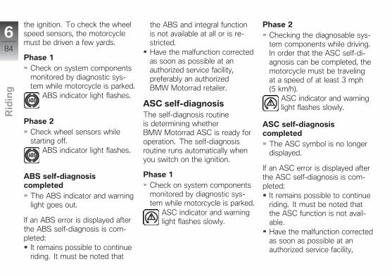
the ignition. To check the wheelspeed sensors, the motorcyclemust be driven a few yards.
Phase 1Check on system componentsmonitored by diagnostic sys-tem while motorcycle is parked.
ABS indicator light flashes.
Phase 2Check wheel sensors whilestarting off.
ABS indicator light flashes.
ABS self-diagnosiscompleted
The ABS indicator and warninglight goes out.
If an ABS error is displayed afterthe ABS self-diagnosis is com-pleted:
It remains possible to continueriding. It must be noted that
the ABS and integral functionis not available at all or is re-stricted.Have the malfunction correctedas soon as possible at anauthorized service facility,preferably an authorizedBMW Motorrad retailer.
ASC self-diagnosisThe self-diagnosis routineis determining whetherBMW Motorrad ASC is ready foroperation. The self-diagnosisroutine runs automatically whenyou switch on the ignition.
Phase 1Check on system componentsmonitored by diagnostic sys-tem while motorcycle is parked.
ASC indicator and warninglight flashes slowly.
Phase 2Checking the diagnosable sys-tem components while driving.In order that the ASC self-di-agnosis can be completed, themotorcycle must be travelingat a speed of at least 3 mph(5 km/h).
ASC indicator and warninglight flashes slowly.
ASC self-diagnosiscompleted
The ASC symbol is no longerdisplayed.
If an ASC error is displayed afterthe ASC self-diagnosis is com-pleted:
It remains possible to continueriding. It must be noted thatthe ASC function is not avail-able.Have the malfunction correctedas soon as possible at anauthorized service facility,
684
z Rid
ing

preferably an authorizedBMW Motorrad Retailer.
DTC self-diagnosiswith Dynamic Traction Control(DTC) OE
The self-diagnosis routineis determining whetherBMW Motorrad DTC is ready foroperation. The self-diagnosisroutine runs automatically whenyou switch on the ignition.
Phase 1Check on system componentsmonitored by diagnostic sys-tem while motorcycle is parked.
DTC indicator light flashesslowly.
Phase 2Checks diagnosis-capable sys-tem components when motor-cycle starts to move.
DTC indicator light flashesslowly.
DTC self-diagnosiscompleted
The DTC symbol is no longerdisplayed.
Watch all warning and indicatorlights on the display.
DTC self-diagnosis notcompleted
The DTC function is not avail-able, as the self-diagnosisfunction has not been com-pleted. (To check wheel sen-sors, motorcycle must reacha minimum speed with en-gine running: min 3 mph (min5 km/h))
If a DTC error is indicated afterthe DTC self-diagnosis is com-pleted:
It remains possible to con-tinue riding. It must be noted
that the availability of the DTCfunction is restricted or it is notavailable at all.Have the malfunction correctedas soon as possible at anauthorized service facility,preferably an authorizedBMW Motorrad retailer.
Breaking inEngine
In the period preceding therunning-in check (initial inspec-tion), attempt to change rpmand engine load as frequentlyas possible, avoiding extendedperiods at constant rpm.Choose curvy, slightly hilly sec-tions of road if possible.Observe the engine run-inspeeds.
685
z Rid
ing

Engine run-in speed
<7000 min-1 (Odometer read-ing 0...186 miles (0...300 km))
<9000 min-1 (Odometerreading 186...621 miles(300...1000 km))
no full throttle (Odometerreading 0...621 miles(0...1000 km))
Observe mileage, after whichthe running-in check should beperformed.
NOTICE
The speed is limited by theengine management system upto the running-in check. Thisspeed monitoring function isswitched off during the running-in check by your authorizedBMW Motorrad retailer.
Mileage until running-incheck
300...750 miles(500...1200 km)
Speed monitoringfunction until running-in
check
max 9000 min-1
Brake padsNew brake pads must be run inbefore they achieve their opti-mum friction force. This initialreduction in braking efficiencycan be compensated for by ex-erting greater pressure on thebrake levers.
WARNING
New brake pads.Extension of the braking distance.Accident hazard.
Brake early.
TiresNew tires have a smooth sur-face. This must be roughened byriding in a restrained manner atvarious lean angles until the tiresare run in. This running in proce-dure is essential if the tires are toachieve maximum grip.
WARNING
Loss of adhesion of new tireson wet roads and at extremeangles.Accident hazard
Always think well ahead andavoid extreme angles.
686
z Rid
ing

Shifting gearsShiftpoint light
The shiftpoint light 1 indicatestwo engine speed thresholds tothe driver:
Shifting speedDuring driving the shiftpoint lightindicates the speed at which therider should shift into the next-highest gear.
Shiftpoint light flashes at thepreset frequency: enginespeed will soon reach upshiftrpm
Shiftpoint light goes out: shift-ing speed reached
The engine rpm limits and theupshift light's display characteris-tics can both be adjusted in theSETUP menu.
Speed limitIf the shiftpoint light flashes orlights up during operation whileSPEED ! simultaneously ap-pears in the display this meansthat the preset speed has beenexceeded.
Pro Gear Shift Assistantwith Pro shift assistantOE
The gearshift assistant provideshelp with upward and downwardgear shifts without the clutch orthe accelerator having to be op-erated. This is not an automatictransmission. The rider is an es-sential part of the system and
makes the decision as to whento change gear.
NOTICE
More detailed information on ProGear-shift Assistance can befound in the section "Technol-ogy in detail".
NOTICE
When changing gear using thePro Gear-shift Assistance func-tion, the cruise-control systemis automatically deactivated forsafety reasons.
687
z Rid
ing

The gears are shifted into asusual with foot force on theshift lever.The sensor 1 on the gear-shiftrod detects the intention tochange gear and initiates gear-shift assistance.When driving at constantspeed in low gears at highrevs, changing gear withoutusing the clutch can result inmajor load change reactions.BMW Motorrad recommendsonly changing gear using theclutch in such situations. Theshifting assistant should not
be used in the area of the rev-limiter.No shifting support is providedin the following situations:If the clutch is operatedIf the gear lever is not in thezero positionWhen upshifting with the throt-tle closed (overrun mode) orwhen deceleratingTo be able to make anothergear shift using gear-shift as-sistance, the gear lever mustbe fully released after the firstgear change.
BrakesHow do you achievethe shortest stoppingdistances?The dynamic load distribution be-tween the front and rear wheelchanges during braking. Theheavier you brake, the greaterthe weight transfer to the front
wheel. Increases in the load onan individual wheel are accom-panied by a rise in the effectivebraking force that the wheel canprovide.To achieve the shortest possi-ble braking distance, the frontbrake must be applied quicklyand with progressively greaterlevels of force. This procedureprovides ideal exploitation of theextra weight transfer to the frontwheel. The clutch should also bedisengaged at the same time.Locking up of the front wheelis prevented by BMW MotorradRace ABS.With the frequently instructed"forced braking," in which thebrake pressure is generated asquickly as possible and with greatforce, dynamic load distribu-tion lags behind the progres-sive increases in decelerationrate and the braking force cannotbe completely transferred to the
688
z Rid
ing

road surface. Due to the miss-ing wheel load, the ABS mustalready prevent a tendency of thefront wheel to lock up with min-imal braking action. This resultsin a reduced braking action.
Descending mountainpasses
WARNING
Braking only with the rear-wheel brake when descend-ing mountain passes.Loss of braking action. Destruc-tion of the brakes caused byoverheating.
Use both front and rear brakes,and make use of the engine'sbraking effect as well.
Wet, soiled brakesMoisture and dirt on the brakerotors and the brake pads resultin a decrease in the braking ac-tion.Delayed or poorer braking actionmust be expected in the follow-ing situations:
When driving in the rain andthrough puddles.After washing the vehicle.When driving on roads spreadwith salt.After working on the brakesdue to oil or grease residues.When driving on soiled roadsor offroad.
WARNING
Moisture and dirt.Poorer braking action.
Brake until brakes are dry orclean; clean if necessary.
Brake early until the full brakingaction is available again.
Parking yourmotorcycleSide stand
Switch off engine.On a grade, the motorcycleshould always face uphill; se-lect 1st gear.
ATTENTION
Poor ground conditions inarea of stand.Component damage caused bytipping over.
Always check that the groundunder the stand is level andfirm.
Fold out side stand and parkmotorcycle.
689
z Rid
ing

ATTENTION
Loading of the side standwith additional weight.Component damage cause bytipping over.
Do not sit on the motorcyclewhen it is parked on the sidestands.
If the slope of the road permits,turn the handlebars to the left.
RefuelingFuel specificationsFor optimal fuel economy, thegasoline should be sulfur-free orvery low in sulfur content.
ATTENTION
Leaded fuel.Damage to the catalytic con-verter.
Do not refuel with leaded gaso-line or gasoline with metallic
additives, e.g. manganese oriron.
ATTENTION
Use of Ethanol E85 as fuel.Damage to the engine and fuelsupply.
Do not refuel with E85, i.e. fuelwith an ethanol content of 85%, or with Flex Fuel.
Fuels with a maximum ethanolcontent of 10 %, i. e., E10,may be used for refueling.
Recommended fuel qual-ity
Premium grade unleaded fuel(max. 10 % ethanol, E10)91 AKI (98 ROZ/RON)91 AKI
Alternative fuel quality
Super unleaded (minor restric-tions with regard to power andfuel consumption) (max. 10 %ethanol, E10)89 AKI (95 ROZ/RON)89 AKI
Refueling
WARNING
Fuel is highly flammable.Fire and explosion hazard.
Do not smoke. Never bringa naked flame near the fueltank.
WARNING
Escaping of fuel due to ex-pansion under exposure toheat with overfilled fuel tank.Accident hazard
690
z Rid
ing

Do not overfill the fuel tank.
ATTENTION
Fuel attacks plastic surfaces.Surfaces become unattractive orcloudy.
Immediately clean plastic partsafter contact with fuel.
Make sure ground is level andfirm and place motorcycle onside stand.
NOTICE
The available fuel tank volumecan only be optimally used withthe vehicle standing on the sidestand.
Open protective cap.
Unlock fuel tank cap 1 withignition key and fold up.
Refuel with a fuel meeting thespecifications above, continu-ing until fuel is no higher thanlower edge of filler neck.
NOTICE
When refueling after running onfuel reserve, the resulting totalfuel quantity must be greaterthan the fuel reserve, so that thenew filling level is detected andthe fuel warning light is switchedoff.
NOTICE
The "usable fuel quantity" spec-ified in the technical data is thefuel quantity, which can be re-fueled if the fuel tank was com-pletely emptied, i.e., if the enginedies off due to lack of fuel.
Usable fuel quantity
Approx. 4.6 gal (Approx.17.5 l)
691
z Rid
ing

Fuel reserve
Approx. 1.1 gal (Approx. 4 l)
Press fuel tank cap down firmlyto close.Remove key and close protec-tive cap.
Secure motorcycle fortransport
Protect all component surfacesagainst which straps are routedagainst scratching. For exam-ple, use adhesive tape or softcloths.
ATTENTION
Motorcycle tips to the sidewhen raising.Component damage cause bytipping over.
Secure the motorcycle againsttipping to the side, preferablywith the assistance of a secondperson.
Push motorcycle onto transportsurface, and do not place onside stand.
ATTENTION
Pinching of components.Component damage
Do not pinch components,e.g. brake lines or wiringharnesses.
Lay straps at front over lowerfork bridge on both sides.Tension straps downward.
692
z Rid
ing

Fasten rear straps on bothsides to the passenger foot-pegs and then tighten them.Tension all straps evenly; themotorcycle should be pulleddown against its springs withthe suspension compressed asmuch as possible.
693
z Rid
ing

694
z Rid
ing

On the racetrack
Display for racing mode . . . . . . . . . . . . . 96
LAPTIMER . . . . . . . . . . . . . . . . . . . . . . . . . 98
RACE INFO. . . . . . . . . . . . . . . . . . . . . . . . 103
SETUP MENU . . . . . . . . . . . . . . . . . . . . . 111
SETUP DDC-SYS . . . . . . . . . . . . . . . . . 117
SETUP EQUIPMENT . . . . . . . . . . . . . . 118
SETUP RACETRACK . . . . . . . . . . . . . 120
SETUP USER-MODE . . . . . . . . . . . . . 125
DTC . . . . . . . . . . . . . . . . . . . . . . . . . . . . . . . 127
Start of race . . . . . . . . . . . . . . . . . . . . . . . 128
Speed limiter for pit lane . . . . . . . . . . . 130
Mirror removal and installation . . . . . 131
Removing and installing license-plate carrier . . . . . . . . . . . . . . . . . . . . . . . . 132
Removing and installing front turnindicator . . . . . . . . . . . . . . . . . . . . . . . . . . . 134
Shift pattern reversal . . . . . . . . . . . . . . . 136
Connector for optional acces-sories . . . . . . . . . . . . . . . . . . . . . . . . . . . . . . 138
795
z On
th
e r
ac
etr
ac
k

Display for racing modeMultifunction display
1 Current angle of inclinationduring cornering
2 Direction for angle of incli-nation\ = left| = vertical/ = right
3 Maximum angle of inclina-tion for left and rightFactory setting for BANKDISP ( 119)
4 ABS control interventionduring brakingDeactivate ABS ( 50)Activating ABS ( 51)
5 Current deceleration duringbrakingFactory setting for BRAKEDISP ( 120)
6 Maximum deceleration7 Maximum DTC torque re-
duction
796
z On
th
e r
ac
etr
ac
k

8 DTC torque reductionwith Dynamic TractionControl (DTC)OE
Factory setting for DTCDISP ( 119)
9 DTC settingwith Dynamic TractionControl (DTC)OE
Adapt DTC ( 127)
797
z On
th
e r
ac
etr
ac
k

LAPTIMERMultifunction display
1 Speed2 Coolant temperature3 Intake air temperature
4 LAP TIMERThe display in these linescan be switched over.Individualize LAPTIMER( 100).LAPTIMER display struc-ture ( 121)In illustration:RUN: Running time of thecurrent lap.BESTLAP: Fastest of thecurrently saved laps.
5 Gear indicator6 Riding mode ( 53)
Marking displayed value
The following times can beshown in the third line:
The time of the previous lap ismarked with "LASTLAP".The running time of the currentlap.
The following times can beshown in the fourth line:
The fastest of the stored laps,marked with "BESTLAP".The all-time best lap time,without a marking.The running time of the currentlap.
The possible combinations aredescribed on Page ( 121).
The stopped time of the pre-ceding lap is shown briefly at thestart of each new lap before thedisplay switches over to the run-ning time of the current lap. Theduration of this delay can be setas described on Page ( 123).
798
z On
th
e r
ac
etr
ac
k

Overview of LAP TIMER
— Solid line: briefly pressbutton.
‑ ‑ Dotted line: press and holdbutton.
1 OdometerStandard displaySelect displays in multi-function display ( 46).
2 Individualize LAPTIMER( 100).
3 Start time recording( 100).
4 Interrupt/continue time en-try ( 101)
799
z On
th
e r
ac
etr
ac
k

Individualizing LAPTIMER
Activate standard display( 109).The odometer (ODO) is dis-played.Briefly press SET 2.The LAPTIMER is opened andshows RUN 3 and BEST-LAP 4 in the factory setting.To change content of lines 3and 4 in LAPTIMER, repeat-edly press and hold SET 2 un-til lines 3 and 4 are displayedas desired.The desired LAPTIMER displaystructure is adopted and saved.
LAPTIMER display structure( 121)
Starting time recording
The LAPTIMER is opened.
Press button 1 to start record-ing.
NOTICE
For the headlight flasher signalto be detected, the engine mustbe running and the motorcyclemoving.
Time recording RUN 2 is run-ning.
When driving over Start/Finishline, press button 1 again tostart recording for next racelap.The data of the preceding racelap will be saved.RUN 2 restarts at00:00:00.If the display mode is exitedduring a recording, then therecording continues to run.However, the recording of anew lap can only be started inthe other modes with an exter-nal signal.
Infrared receiver
with infrared receiverOA
The LAPTIMER can be conve-niently operated with an infraredsignal. On this, the followingshould be noted:
7100
z On
th
e r
ac
etr
ac
k

The infrared receiver availableas an optional accessory mustbe connected to the connectorfor optional accessories underthe right-hand fairing side panel( 138).In the SETUP RACETRACK,the LAPTIMER trigger modemust be set to LAPTM TRIGAUTO or LAPTM TRIG EX-TERN ( 124).
Operation with the headlightflasher button is also possiblewith the integrated infrared re-ceiver. For this purpose, theLAPTIMER trigger mode mustbe set to LAPTM TRIG AUTO orLAPTM TRIG MANUAL.To avoid the premature detectionof a completed lap due to inter-ference signals, a minimum laptime can be specified ( 124).Signals received before this timeexpires are then ignored.
Interrupting time entry
Time recording is running.
Press and hold TRIP 1 to inter-rupt time recording.Press and hold TRIP 1 to con-tinue time recording.
Ending time entry
Time recording is running.
Press and hold TRIP 1 to stoptime recording.Briefly press button 2.The indicated time is deleted:--:--:--Time recording is ended.No lap time is saved.Briefly press TRIP 1 to exit laptimer.
NOTICE
If additional laps are recordedat a later time, the numberingof the laps is continued.Numbering does not begin withlap 1 again until after all laps
7101
z On
th
e r
ac
etr
ac
k

have been deleted from theRACE INFO.
ODO is displayed.
Fastest lap expected
This function must be activatedin the SETUP RACETRACKmenu ( 124).
When a new lap is started theintermediate elapsed times aremonitored at 100 meter intervalsand then compared with the cor-responding elapsed times for thefastest recorded lap. If the cur-rent intermediate elapsed time is
better than that of the previousfastest lap then a new fastest lapcan be anticipated. The "fastestlap" light 1 lights up.
7102
z On
th
e r
ac
etr
ac
k

RACE INFORACE INFO Part 1
— Solid line: briefly pressbutton.
‑ ‑ Dotted line: press and holdbutton.
1 Delete all-time best lap.2 Information on the current
best lap.Three displays in alterna-tion.Information on each racelap ( 106)
3 Deleting currently best lap.4 Information on the last lap.5 Deleting the last lap.6 Information on additional
laps.Select saved lap ( 105).Delete lap ( 108).
7103
z On
th
e r
ac
etr
ac
k

RACE INFO Part 2
— Solid line: briefly pressbutton.
‑ ‑ Dotted line: press and holdbutton.
1 Information on lap 01.Select saved lap ( 105).Information on each racelap ( 106)
2 Delete lap ( 108).3 Information on lap 02.4 Total of all lap times and
lap distances.5 Clear recording ( 108).6 Delete all-time best lap.7 Exit RACE INFO ( 109).
Activate standard display( 109).
7104
z On
th
e r
ac
etr
ac
k

Selecting saved lap
RACE INFO is displayed.
Briefly press TRIP 1 or SET 2to display saved laps consecu-tively.
NOTICE
If the rider pulls away inthis mode, the displayautomatically switches over tothe LAPTIMER.
When SET 2 is pressed, thestored laps and functions aredisplaced in the following or-der; each time TRIP 1 is pressed,
they are displayed in the reverseorder:
All-time best lap time BEST-EVERBest stored lap time BESTLast stored lap time LASTAll other stored laps LAP 01… LAP 60The totals of all saved laptimes and lap distancesTOTALDelete the stored dataDELETE LAPSDelete the stored best lapBEST-EVER DELETEExiting RACE INFO RACEINFO EXIT
7105
z On
th
e r
ac
etr
ac
k

Information on each racelap
1 In alternation for the in-dicted lap:Top speed (max)Average speed (Ø)Minimum speed (min)
2 Maximum angle of incli-nation for left and right ofindicated lap
3 Race lap to which dis-played data refer
4 Lap time of displayed racelap
5 In alternation for the in-dicted lap:Average gas utilization(THROT) in percentRiding share with brake ac-tuation (BRAKE) in percentNumber of gearshifts(GEAR) in the indicated lap
6 Distance of indicated lapcovered
7106
z On
th
e r
ac
etr
ac
k

7 ABS control intervention:"ABS" displayed = lap withABS control intervention"ABS" hidden = lap with-out ABS control interven-tion
8 Maximum deceleration inthe indicated lap
9 Maximum DTC torque re-duction in the indicated lap
10 DTC setting in the indi-cated lap
11 Riding mode in the indi-cated lap
7107
z On
th
e r
ac
etr
ac
k

Clearing recording
RACE INFO is displayed.
Briefly press TRIP 1 or SET 2repeatedly until DELETELAPS is displayed.Press and hold SET 2 todelete all recorded data.BEST-EVER DELETE isindicated.Either briefly press SET 2 toskip deleting of all-time bestlap.Or press and hold SET 2 todelete data of all-time best lap.
BEST-EVER is deleted:--:--:--All recordings have now beendeleted.RACE INFO EXIT is dis-played.
All-time best lap
The all-time best lap (BEST-EVER) is the fastest of allrecorded racing laps and isupdated as soon as a faster laphas been recorded.The all-time best lap remainsstored even if the recorded lapsare deleted. As a result, a newrace can be recorded at othertimes and compared with thebest lap from previous races.The all-time best lap can also bedeleted.If the all-time best lap is from astored recording, the correspond-ing lap number is also displayed.If the all-time best lap does nothave a lap number, it is from a
recording that has already beendeleted.
Deleting lap
RACE INFO is displayed.
Briefly press TRIP 1 or SET 2repeatedly until lap to bedeleted is displayed.Press and hold SET 2 todelete lap.If one of the recorded laps isdeleted, it is replaced as fol-lows:BEST-EVER: The best lapsaved is adopted as the newall-time best lap time.
7108
z On
th
e r
ac
etr
ac
k

BEST: The lap that previouslyhad been the second best lapis adopted as the new best lap.LAST: The lap that previouslyhad been the second-to-the-last lap is adopted as the newlast lap.If any desired saved lap hasbeen deleted, the followingmust be taken into account:The deleted lap is subtractedfrom the overall time.The deleted lap is subtractedfrom the overall time.The numbering of the remain-ing laps is maintained.
Exiting RACE INFO
Briefly press TRIP 1 or SET 2repeatedly until RACE INFOEXIT is displayed.Press and hold SET 2 to exitRACE INFO.The recorded values arestored.
Activating standarddisplay
Press and hold TRIP 1.
NOTICE
Regardless of what the multi-function display shows, the stan-dard display with the odometerODO is always shown by press-ing and holding TRIP 1.The only exceptions are the fol-lowing displays:LAPTIMER with running/stoppedtime recording: pressing andholding TRIP 1 stops timerecording or continues it.
7109
z On
th
e r
ac
etr
ac
k

Pressing and holding LIMIT:TRIP 1 switches the speed warn-ing off (LIMIT OFF).
ODO is displayed.
7110
z On
th
e r
ac
etr
ac
k

SETUP MENUOverview SETUP MENU
— Solid line: briefly pressbutton.
‑ ‑ Dotted line: press and holdbutton.
1 Select submenu ( 113)2 Display submenu
with Dynamic DampingControl (DDC) OE
SETUP DDC-SYS( 113)Set parameter ( 115)
3 Display submenuSETUP EQUIPMENT( 113)
4 Display submenuSETUP RACETRACK( 114)
7111
z On
th
e r
ac
etr
ac
k

5 Display submenuOnly with USER ridingmode active
with Pro riding modesOE
SETUP USER-MODE( 115)
6 Reset all parameters FAC-TORY RESET
7 Exit SETUP MENÜExit settings ( 116)
7112
z On
th
e r
ac
etr
ac
k

Selecting submenu
Switch on ignition ( 40).Briefly press SET 2 repeatedlyuntil SETUP MENU ENTERis displayed.
NOTICE
If the display has been scrolledtoo far, briefly press SET 2 re-peatedly until the menu returnsto the start and finally to the de-sired display.
Press and hold SET 2.
Briefly press TRIP 1 or SET 2repeatedly until desired sub-menu is displayed.Press and hold SET 2 to opendesired submenu.
When SET 2 is pressed, thepossible parameters are dis-played in the following order;each time TRIP 1 is pressed,they are displayed in the reverseorder.
SETUP DDC-SYS
with Dynamic Damping Control(DDC) OE
SETUP DDC-SYSRebound stage damping, rearREAR REBRear compression-stage damp-ing REAR COMWithout spring travel sensorfor front forks: Front dampingFRONT DMP
With spring travel sensor forfront forks: Front rebound-stage damping FRONT REBWith spring travel sensor forfront forks: Front compressiondamping FRONT COMZero calibration CALIBActivate SET-DR ON (Dur-ing Ride) or deactivate SET-DR OFF adjustable dampingwhile riding.Reset DDC settings of cur-rent riding mode RESET AC-TUAL.Reset DDC settings of all ridingmodes RESET ALL.
SETUP EQUIPMENT
SETUP EQUIPMENTwith anti-theft alarm system(DWA)OE
Automatically activate the alarmfunction of the anti-theft alarmsystem after switching offthe ignition DWA AUTO ON
7113
z On
th
e r
ac
etr
ac
k

or leave deactivatedDWA AUTO OFF.Set time displayCLOCK TIME.Set brightnessDISP BRIGHT.Switch speed warning onWARN SPEED ON or offWARN SPEED OFF.Switch display for light faulton WARN LAMP ON or offWARN LAMP OFF.Switch off the display for thecurrent angle of inclinationBANK DISP OFF or switchit on with the desired updateinterval: BANK DISP FAST,BANK DISP MID orBANK DISP SLOWwith Dynamic Traction Control(DTC)OE
Switch the display for the cur-rent and maximum DTC torquereduction on DTC DISP ONor off DTC DISP OFF.
Switch the display for the cur-rent and maximum delay onBRAKE DISP ON or offBRAKE DISP OFF.Submenu for switching overthe units for the odometerdisplay, residual-range display,temperature display, averageconsumption display and timedisplay UNITS
SETUP EQIP:UNITS
SETUP EQIP:UNITSChange over the temperatureunit: UNIT TEMP DEG: Cor UNIT TEMP DEG: FChange over the aver-age consumption unit:UNIT CONS L⁄100,UNIT CONS MPG: US,UNIT CONS MPG: UK orUNIT CONS KM⁄LSet the 24 or 12-hourmode for the time display:
UNIT CLOCK 24 orUNIT CLOCK 12
SETUP RACETRACK
SETUP RACETRACKSwitch-on speed for shiftpointlight GSL ON-RPM (GearShift Light)Switch-off speed for shiftpointlight GSL OFF-RPMShiftpoint light brightnessGSL BRIGHTShiftpoint light flashing fre-quency GSL FREQSet LAPTIMER displayversion: Running lap timeLAPTM RUN, the requiredtime for the previous lapLAPTM LAST, best lap timeLAPTM BEST, the total ofall saved lap times and lapdistances LAPTM TOTAL,all-time best lap timeLAPTM BEST-EVER
7114
z On
th
e r
ac
etr
ac
k

Display duration forlast stopped lap timeLAPTM HOLDAnti-rebound time (waitingtime until new lap can bestarted) of the headlightflasher button for the LAPTIMER LAPTM DEB-TM inseconds or LAPTM DEB-TM CUSTOM in minutes andseconds.If the fastest lap is expected,this can be displayed with the"Fastest lap" light BLIP ON( Best Lap In Progress) or notdisplayed BLIP OFF.with infrared receiverOA
Changeover of the headlightflasher button for starting timerecording. LAPTM TRIGAUTO: Operation via headlightflasher button or infrared re-ceiver; LAPTM TRIG MAN-UAL: Operation only via head-light flasher button; LAPTM
TRIG EXTERN: Operationonly via infrared receiver.with Pro riding modesOE
Adjust the speed for the pitlane limiter PIT LIMIT …or switch off the pit lane limiterPIT LIMIT OFF.
SETUP USER-MODE
with Pro riding modesOE
SETUP USER-MODEAntilock brake system for rac-ing tires ABS SLICKSport mode for antilock brakesystem ABS SPORTAntilock brake system forracing with series tiresABS RACEDynamic traction control forracing tires DTC SLICKDynamic traction controlfor racing with series tiresDTC RACESport mode for dynamic trac-tion control DTC SPORT
Dynamic traction control forwet roads DTC RAINSport mode for Dy-namic Damping ControlDDC SPORTDynamic Damping Controlfor racing with series tiresDDC RACEDynamic Damping Control forracing tires DDC SLICKThrottle response for racingmode ENGINE RACEThrottle response for wet roadsENGINE RAINReset all USER MODE settingsRESET.
Setting parameter
Parameter is indicated.
7115
z On
th
e r
ac
etr
ac
k

Press and hold SET 2 until dis-played parameter begins toflash.Briefly press TRIP 1 or SET 2repeatedly until desired value isdisplayed.
If desired value is displayed:Press and hold SET 2 until dis-played value no longer flashes.The value has been saved.
Exiting settings
Press and hold TRIP 1until multifunction display isswitched over to standarddisplay.A flashing value will still besaved.As an alternative: repeatedlypress TRIP 1 or SET 2 untilSETUP … EXIT is shown inthe respective submenu.Press and hold SET 2 to exitsubmenu.SETUP … ENTER is indi-cated.
Repeatedly press TRIP 1 orSET 2 until SETUP MENUEXIT is displayed.Press and hold SET 2 to exitSETUP MENU.SETUP MENU ENTER isindicated.
7116
z On
th
e r
ac
etr
ac
k

SETUP DDC-SYSwith Dynamic Damping Control(DDC) OE
Adjusting rear damping
Rebound stage damping adjust-ment on the rear spring strut.Reading display range
-7 (soft) … +7 (stiff)Factory setting: 0
Compression stage damping ad-justment on the rear spring strut.Reading display range
-7 … +7Factory setting: 0
Adjusting front damping
Damping adjustment on the frontspring strut without separationbetween compression and re-bound stage.Reading display range
-7 … +7Factory setting: 0
NOTICE
The spring travel sensorrequired for the separateadjustment of the rebound andcompression stage is not offeredby BMW Motorrad. It is available
7117
z On
th
e r
ac
etr
ac
k

as racing accessory. Furtherinformation can be requestedunder "[email protected]".
Leveling sensorcalibration
Calibration of the leveling sensoron the rear spring strut, e.g. af-ter changes to the running gearheight ( 77)
SETUP EQUIPMENTDisplay brightness
Five different intensities are avail-able for adjusting the displaybrightness.Reading display range
1, 2, 3, 4, 5Factory setting: 5
Speed warning
The speed is set in the LIMITdisplay. If the riding speedexceeds this limit, SPEED!is displayed as a warning andthe shiftpoint light lights up orflashes.Reading display range
ON, OFFFactory setting: OFF
7118
z On
th
e r
ac
etr
ac
k

Light error
If the turn indicators are removedor the license plate carrier is de-tached for track use, the vehicle'selectronic monitoring system willinterpret this as a defective lightor light source and the corre-sponding warning message willappear in the display.This function enables the displayto be suppressed.Reading display range
ON, OFFFactory setting: ON
Lean angle
Adjustment of the display for an-gle of inclination: angle of incli-nation, direction for angle of incli-nation and maximum angle of in-clination of the current lap for leftand right. The interval for updat-ing the display can be adjustedfor the display can be hidden.Reading display range
OFF, FAST, MID, SLOWFactory setting: OFF
Dynamic Traction Controlwith Dynamic Traction Control(DTC) OE
Adjustment of the displays forDTC: Current and maximum DTCtorque reduction and DTC set-ting. The displays can be dis-played and hidden.Reading display range
OFF, ONFactory setting: OFF
7119
z On
th
e r
ac
etr
ac
k

Deceleration
Adjustment of the displays fordeceleration: Current and max-imum deceleration in m⁄s², andABS intervention. The displayscan be displayed and hidden.Reading display range
OFF, ONFactory setting: OFF
SETUP RACETRACKSwitch-on speed ofshifting flasher
Adjustment of the switch-onspeed for the shiftpoint light.Reading display range
7000, 9000, 10000, 11000,12000, 12500, 13000, 13500,14000Factory setting: 7,000Only speeds which lie belowthe switch-off speed can beselected.
Switch-off speed ofshifting flasher
Adjustment of the switch-offspeed for the shiftpoint light.Reading display range
9000, 10000, 11000, 12000,12500, 13000, 13500, 14000,16000Factory setting: 16000Only speeds which lie abovethe switch-on speed can beselected.
7120
z On
th
e r
ac
etr
ac
k

Brightness of shiftingflasher
Adjustment of shifting flasherbrightness as a percentage ofthe maximum brightness.The shifting flasher remainsswitched on during setting andis immediately adjusted to theselected brightness.Reading display range
20, 30, 40, … 100Factory setting: 100
Flashing frequency ofshiftpoint light
Adjustment of the flashing fre-quency of the shiftpoint light andthe speed warning in Hz (cyclesper second).Reading display range
0, 4, 8Factory setting: 4When 0 is selected, the shift-point light and the speed warn-ing remain on constantly.When 4 is selected, the shift-point light and the speed warn-ing flash slowly.
When 8 is selected, the shift-point light and the speed warn-ing flash rapidly.
LAPTIMER displaystructureThe LAPTIMER display struc-ture can be selected from six ver-sions.
Version 1 (factory setting)The running time of the currentlap is shown in the third line andthe best lap time of the storedvalues is shown in the fourth line.
7121
z On
th
e r
ac
etr
ac
k

Version 2The required time of the previouslap is shown in the third line andthe running time of the currentlap is shown in the fourth line.
Version 3The required time of the previouslap is shown in the third line andthe best lap time of the storedvalues is shown in the fourth line.
Version 4Running time of the current lapis shown in the third line and thetotal of all lap times is shown inthe fourth line.
7122
z On
th
e r
ac
etr
ac
k

Version 5The funning time of the cur-rent lap is shown in the third lineand the all-time best lap time( 108) is shown in the fourthline.
Version 6The third line remains empty andthe running time of the currentlap is shown in the fourth line.
Display duration for laststopped time
Adjustment of the display dura-tion in seconds.After the start of a new lap, themeasured lap time of the pre-vious lap is displayed for theHOLD set time. Then the run-ning time of the current lap isshown again.Reading display range
0, 3, 8, 13, 18, … 30Factory setting: 3
7123
z On
th
e r
ac
etr
ac
k

Minimum lap time
When determining the lap times,the time can be set which mustelapse after the first received sig-nal before a new signal is ac-cepted.
Within this anti-rebound time,the headlight flasher can beused without the signal for anew lap being output.When an infrared receiver isused, this prevents the signalsof several transmitters posi-tioned next to each other frombeing evaluated.
Reading display range0, 10, 30, 45, 60, CUSTOMFactory setting: 10
When CUSTOM is selected, theanti-rebound time can be en-tered in minutes and seconds(MM:SS).Reading display range
00:00 … 99:99Factory setting: 01:00
Fastest lap
The "fastest lap expected" func-tion ( 102) is activated or de-activated.Reading display range
ON, OFFFactory setting: ON
LAP TIMER trigger modewith infrared receiverOA
7124
z On
th
e r
ac
etr
ac
k

The various possibilities for start-ing time recording are set.Reading display range
AUTO, EXTERN, MANUALFactory setting: AUTOAUTO: Both the headlightflasher button and the lap trig-ger are accepted as a triggersource.EXTERN: Only the lap trigger isaccepted as a trigger source.MANUAL: Only the headlightflasher button is accepted as atrigger source.
Speed limiter for pit lanewith Pro riding modesOE
Adjustment of the maximumspeed (±100) of the engine whenriding in the pit lane in 1st gearwith the start button pressed. Ifexceeded, the engine speed islimited. The speed limiter for thepit lane can also be deactivated.Reading display range
4000, 4100, 4200, …, 8000,OFFFactory setting: OFF
SETUP USER-MODEABS
Adjustment of antilock brake sys-tem ABS in USER-MODE.Reading display range
SPORT, RACE, SLICKFactory setting: SLICKThe checkmark is only dis-played if an adjustment hasbeen made!With checkmark: The specifiedvalue has been adopted by theABS.Without checkmark: Thespecified value has not beenadopted.
7125
z On
th
e r
ac
etr
ac
k

DTC
Adjustment of the Dynamic Trac-tion Control DTC in the USER-MODE.Reading display range
RAIN, SPORT, RACE, SLICKFactory setting: SLICKThe checkmark is only dis-played if an adjustment hasbeen made!With checkmark: The specifiedvalue has been adopted by theDTC.Without checkmark: Thespecified value has not beenadopted.
DDC
Adjustment of the DynamicDamping Control DDC in theUSER-MODE.Reading display range
SPORT, RACE, SLICKFactory setting: SPORTThe checkmark is only dis-played if an adjustment hasbeen made!With checkmark: The specifiedvalue has been adopted by theDDC.Without checkmark: Thespecified value has not beenadopted.
ENGINE
Adjustment of the ENGINEthrottle response in the USER-MODE.Reading display range
RAIN, RACE, SLICKFactory setting: SLICKThe checkmark is only dis-played if an adjustment hasbeen made!With checkmark: The specifiedvalue has been adopted by theENGINE.Without checkmark: Thespecified value has not beenadopted.
7126
z On
th
e r
ac
etr
ac
k

DTCwith Dynamic Traction Control(DTC) OE
DTC settingThe permissible slip on the rearwheel is controlled by the DTCaccording to the selected ridingmode.In the SLICK and USER ridingmodes, it is also possible to ad-just the system-dependent DTCsetting.
Adapting DTCActivate SLICK or USERriding mode by installing codingplug if necessary.
NOTICE
The DTC can only be adjustedin the SLICK and USER ridingmodes.
NOTICE
The DTC can also be adjustedwhile riding.
Briefly press button 1 (+) toincrease value 3.
WARNING
Loss of stability with spin-ning rear wheel caused byreduction of DTC control.Accident hazard
Reduce DTC control on racetracks only.
Briefly press button 2 (-) to de-crease value 3.The set value 3 is shown inthe multifunction display and isbetween -7 and +7:+1 … +7: Reduction of slipat rear wheel by a maximumof seven steps. The value +7is equal to the earliest DTCintervention.-1 … -7: Increasing of slipat rear wheel by a maximumof seven steps. The value -7 is equal to the latest DTCintervention.0: Factory settingDTC display and value 3 hid-den: DTC activated.
DTC switch-offOn very loose substrates (e.g.a gravel bed at a racetrack) theinterventions of the DTC can re-duce the drive force at the rearwheel to such a degree that therear wheel no longer turns. In
7127
z On
th
e r
ac
etr
ac
k

this case, BMW Motorrad rec-ommends switching off the DTCtemporarily.Note that the rear wheel will spinin the loose substrate, and closethe throttle in a timely mannerbefore reaching a solid substrate.Then switch on the DTC again.
Start of racewith Pro riding modesOE
Launch ControlLaunch Control supports therider in maintaining the idealspeed for a race start. LaunchControl can only be activated inthe SLICK and USER ridingmodes.
Engine speed after acti-vation of launch control
at full throttle
9000 min-1
When L-CON is active, theengine torque is reduced so
that, for example, the maximumpropulsion on level ground is setwith the front wheel slightly liftingoff. If the front wheel is detectedas lifting off, the torque is tem-porarily slightly reduced. From aspeed the speed limiter is deacti-vated.
Speed for deactivationof speed governing for
launch control
Approx. 43 mph (Approx.70 km/h)
Launch Control is switched offunder the following conditions:
Third gear is engaged.Angle becomes greater than30°.Engine or ignition is switchedoff.Riding mode is changed.
The number of subsequent startswith Launch Control is limited forclutch protection. The numberof starts still possible is shown inthe display.
Race start with LaunchControl
CAUTION
Launch Control allows max-imum acceleration, whichcould cause unfamiliar rid-ing situations.Risk of injury due to increasedacceleration.
Only use Launch Control onrace tracks.
Activate SLICK or USERriding mode.Bring motorcycle in start posi-tion.Vehicle is standing, engine isrunning.
7128
z On
th
e r
ac
etr
ac
k

Press and hold the starter but-ton 1 until the display changes.Check display.
The number of starts still possi-ble is shown in the display 1 withLaunch Control and L-CON.
Start with Launch Control possi-ble.
Perform start as described be-low.
If no start with Launch Control iscurrently possible, the number 0is displayed with an exclamationmark 1 added.
Let the clutch cool down.
Clutch cool-down time
Approx. 3 min (With the en-gine running)
Clutch cool-down time
Approx. 20 min (With the en-gine switched off)
Perform start as usual, openthrottle grip at least to suchan extent that speed limiting isreached.Open throttle grip completelyafter clutch engagement.
Shiftpoint light lights up orflashes.
Launch Control controls theideal torque at the rear wheeland maintains a constant en-gine speed up to the speedspecified below.Leave throttle grip completelyopen.
7129
z On
th
e r
ac
etr
ac
k

Speed for deactivationof speed governing for
launch control
Approx. 43 mph (Approx.70 km/h)
Due to the full-throttle positionof the throttle grip, the enginespeed increases, as soon asspeed limiting is deactivated.The throttle grip reacts again inthe accustomed manner.Depending on the race course,upshifting and cornering at anangle.When third gear is engagedor the angle becomes greaterthan 30°, the … L-CONdisplay disappears.The start of a race is com-pleted with Launch Control.
Speed limiter for pitlane
with Pro riding modesOE
Ride in 1st gear.
NOTICE
The maximum speed PITLIMIT … must be set inthe SETUP RACETRACKsubmenu.The speed resulting from themaximum speed is dependent onthe transmission ratio and the tiresize.
Hold down starter button 1.Twist throttle grip open untilPIT LIMIT … is reached.The engine speed is limitedwith ignition interruption.
WARNING
When the starter button isreleased, the engine accel-erates according to the posi-tion of the throttle grip.Risk of accident by violent jerkwith throttle grip in full load posi-tion.
Do not open the throttlegrip completely, but insteadonly until the limit speed isreached.
Release starter button 1.The motorcycle accelerateswith maximum acceleration.
7130
z On
th
e r
ac
etr
ac
k

Mirror removal andinstallationRemoving mirror
Make sure ground is level andfirm and park motorcycle.
Remove nuts 1 on left andright and take off mirror.
Secure the paneling 2 on theleft and right to the fairingbracket 3. If cable ties areused, protect possible locationsof abrasion marks using anadhesive strip.
NOTICE
Use the HP Race Cover Kit fromBMW Motorrad to cover the ex-posed screw sockets and securethe mounting attachment.
Installing mirrorsMake sure ground is level andfirm and park motorcycle.
Remove fairing fastener.
Mount mirrors on left and rightin mounts 4.Install nuts on back of fairingwith torque.
Mirror on front panel car-rier
Thread-locking compound:mechanical
6 lb/ft (8 Nm)
7131
z On
th
e r
ac
etr
ac
k

Removing and installinglicense-plate carrierRemove license-platecarrier
ATTENTION
Removing the number platecarrier.Expiry of operating license forpublic roads.
Do not ride on public roadswithout a number platecarrier.
Park motorcycle, ensuring thatsupport surface is firm andlevel.Remove passenger seat( 62).with passenger seat cover OE
Remove hump cover ( 61).
Remove cable tie (arrow)and separate connector 1 forlicense-plate carrier.
NOTICE
If the license plate carrier is re-moved for racetrack use, thevehicle's electronic monitoringsystem will interpret this as adefective light or light sourceand the corresponding warn-ing message will appear in thedisplay. This warning messageis suppressed by activating theWARN LAMP OFF function
in the SETUP EQUIPMENTsubmenu.
Thread out connector 1 withcable through lower rear sec-tion 2.
with anti-theft alarm system(DWA)OE
Unplug connector 1 for anti-theft alarm system.
NOTICE
Before the connector for the anti-theft alarm system is discon-nected, it must be ensured thatthe DWA has been deactivated
7132
z On
th
e r
ac
etr
ac
k

in the SETUP EQUIPMENTsubmenu with the DWA AUTOOFF function.
Remove screw 4.Remove anti-theft alarmsystem 2 while unhooking atbracket 3.
Disconnect connector 1 forlicense-plate carrier.Remove body-bound rivets 2on left and right.Remove bracket 3 for anti-theftalarm system.
Remove screws 4 with wash-ers 3.Take off license-plate car-rier 2 and thread out wiringharness 1.Install the passenger seat( 62).
Install license-platecarrier
Park motorcycle, ensuring thatsupport surface is firm andlevel.Remove passenger seat( 62).
Position license-plate carrier 2and thread in wiring harness 1.Install screws 4 with wash-ers 3.
Number-plate carrier torear frame
4 lb/ft (5 Nm)
7133
z On
th
e r
ac
etr
ac
k

with anti-theft alarm system(DWA)OE
Install bracket 3 for anti-theftalarm system.Install body-bound rivet 2.Fasten connector 1 for license-plate carrier.
Insert anti-theft alarm system 2while hooking into bracket 3.Install screw 4.Connect connector 1 for anti-theft alarm system.
Thread connector 1 with cablethrough lower rear section 2.
Connect connector 1, positionand fasten cable tie (arrow).
NOTICE
If the light defect warningmessage for racetrack use issuppressed in the display, thismust be activated in the SETUPEQUIPMENT submenuunder the SETUP EQIP:WARN LAMP ON functionbefore the motorcycle is put intooperation in road traffic.
Install the passenger seat( 62).
Removing and installingfront turn indicatorRemove front turn signal
NOTICE
The working steps describedhere for the right turn indicator
7134
z On
th
e r
ac
etr
ac
k

also apply logically for the leftside.
Remove fairing side panel( 183).
Detach cable 3 from bracket 4.
Remove screw 1 and take offturn indicator 2.Guide cable through fairingside panel.
Mount fairing side panel 7 inmount 8 on engine spoiler.
Fasten fairing side panel ingrommet 3 and detent pin 4.Install screws 2.
Install screw 1.
7135
z On
th
e r
ac
etr
ac
k

Installing front turn signal
Remove the screw 1 on theinside of the right side panel.
Remove screws 2.Detach fairing side panel fromgrommet 3 and detent pin 4.
Guide cable through fairingside panel.
Position turn signal 2 and in-stall screw 1.
Clip in cable 3 on bracket 4.
Installing fairing side panel( 184).
Shift pattern reversalShift pattern for racingmodeFor the racing mode, the shiftpattern can be reversed by mod-ifying the gear-shift rod. Shiftpattern reversal means that thegearshift lever must be actuatedupward for 1st gear and down-ward for all other gears. Thisis the opposite of operation onpublic roads.
Reversing shift pattern
ATTENTION
Riding with shift pattern re-versal.Expiry of operating license forpublic roads.
Do not use shift pattern rever-sal on public roads.
7136
z On
th
e r
ac
etr
ac
k

Clean thread 1.Slide protective cap 2 ontogear-shift rod 4.Remove screw 3.Remove washer between balljoint and gearshift lever.Reposition gear-shift rod 4 tothread 1.
Insert screw through ball jointand washer and install in threadfor shift pattern reversal.
Shift rod on gearshiftlever
Joint compound: Micro-encapsulated or medium-strength screw lock
6 lb/ft (8 Nm)
Fit the protective cap.The shift pattern reversal hasbeen set up for the racingmode.
with Pro shift assistantOE
Clean thread 1.Slide protective cap 2 ontogear-shift rod 4.Remove screw 3.Remove washer between balljoint and gearshift lever.Reposition gear-shift rod 4 tothread 1.
7137
z On
th
e r
ac
etr
ac
k
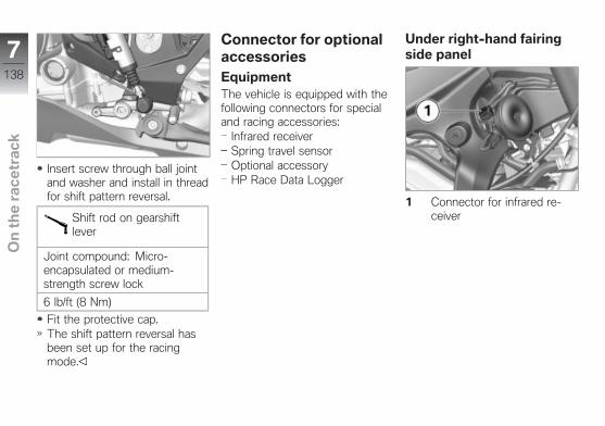
Insert screw through ball jointand washer and install in threadfor shift pattern reversal.
Shift rod on gearshiftlever
Joint compound: Micro-encapsulated or medium-strength screw lock
6 lb/ft (8 Nm)
Fit the protective cap.The shift pattern reversal hasbeen set up for the racingmode.
Connector for optionalaccessoriesEquipmentThe vehicle is equipped with thefollowing connectors for specialand racing accessories:
Infrared receiverSpring travel sensorOptional accessoryHP Race Data Logger
Under right-hand fairingside panel
1 Connector for infrared re-ceiver
7138
z On
th
e r
ac
etr
ac
k

Under left-hand fairingside panel
1 Optional accessories (con-nector with power supply +LIN; e.g. as for navigationsystem)
2 Spring travel sensor forfront forks (racing acces-sory)
Under passenger seatwith anti-theft alarm system(DWA)OE
1 Connector for DWA andHP Race data logger
2 DWA
Under passenger seatwithout anti-theft alarm system(DWA)OE
1 Connector for DWA andHP Race data logger
2 Terminating resistor
Mounting special andracing accessoriesTo access connectors, removerespective fairing side panel, pas-senger seat and/or hump cover.
Remove fairing side panel( 183).Remove passenger seat( 62).with passenger seat cover OE
Remove hump cover ( 61).
7139
z On
th
e r
ac
etr
ac
k

Unlock protective cap or ter-minating resistor and pull offconnector.Mount special or racing acces-sories.
NOTICE
Observe installation instructionsof special or racing accessories.
NOTICE
So that the wiring harness canbe correctly positioned and thewiring harnesses with the con-nectors are not routed under ten-sion, the cable times must not betightened until the end.
ATTENTION
Penetration of dirt and mois-ture in the open connector.Malfunctions
Remount cover cap or termi-nating resistor after removingconnector.
Remount cover cap or termi-nating resistor after removingconnector.Installing fairing side panel( 184).Install the passenger seat( 62).with passenger seat cover OE
Install hump cover ( 62).
7140
z On
th
e r
ac
etr
ac
k

Technology in detail
Anti-Lock Brake System . . . . . . . . . . . 142
Dynamic Damping Control . . . . . . . . . 144
Traction Control . . . . . . . . . . . . . . . . . . . 145
Riding mode . . . . . . . . . . . . . . . . . . . . . . . 146
Pro Gear Shift Assistant . . . . . . . . . . . 152
8141
z Te
ch
no
log
y in
de
tail

Anti-Lock BrakeSystemPartially integral brakeYour motorcycle is equipped witha partially integral brake configu-ration. Both front and rear brakesare applied simultaneously whenyou pull the handbrake lever.The footbrake lever acts only onthe rear brake.
ATTENTION
Spinning the rear wheel withthe front brake applied (BurnOut) is made considerablymore difficult due to the inte-gral function.Damage to rear-wheel brake andclutch.
Only do Burn Outs with theABS switched off.
How does ABS work?The maximum braking force thatcan be transferred to the roadsurface is partially dependent onthe friction coefficient of the roadsurface. Gravel, ice, snow andwet roads offer a considerablypoorer friction coefficient than adry, clean asphalt surface. Thepoorer the friction coefficient ofthe road surface is, the longerthe braking distance will be.If the maximum transferable brak-ing force is exceeded when therider increases the brake pres-sure, the wheels begin to lockand driving stability is lost, and afall can result. Before this situa-tion occurs, ABS intervenes andadjusts the brake pressure to themaximum transferable brakingforce. This enables the wheelsto continue to turn and maintainsdriving stability regardless of theroad surface condition.
What happens whenrough roads areencountered?Bumpy or rough roads can brieflylead to a loss of contact be-tween the tires and the road sur-face, until the transferable brak-ing force is reduced to zero. Ifbraking is carried out in this sit-uation, ABS must reduce thebrake pressure to ensure driv-ing stability when restoring con-tact to the road. At this point intime, the BMW Motorrad IntegralABS must assume extremely lowfriction coefficients (gravel, ice,snow) so that the running wheelsturn in every imaginable case andthe driving stability is ensured.After detecting the actual con-ditions, the system adjusts theoptimum brake pressure.
8142
z Te
ch
no
log
y in
de
tail

In what ways is theBMW Motorrad Race ABSnoticeable to the rider?If the ABS has to reduce thebraking force due to the cir-cumstances described above,vibrations can be felt through thebrake lever.If the brake lever is operated,braking pressure is also built upat the rear wheel via the integralfunction. If the footbrake lever isnot operated until afterwards, thebrake pressure already built upis noticeable as counterpressureearlier than when the footbrakepedal is operated before or at thesame time as the brake lever.
Lifting off rear wheelEven during severe braking, ahigh level of tire grip can meanthat the front wheel does notlock up until very late, if at all.Consequently, ABS does not in-tervene until very late, if at all.
Under these circumstances therear wheel can lift off the ground,and the outcome can be a high-siding situation in which the mo-torcycle can flip over.
WARNING
Lifting off of the rear wheeldue to heavy braking.Accident hazard
When braking heavily, bear inmind that the ABS control can-not always be relied on to pre-vent the rear wheel from liftingoff the ground.
Special situationsTo detect the tendency of thewheels to lock up, the speedsof the front and rear wheel arecompared. If implausible valuesare detected over an extendedperiod of time, the ABS functionis deactivated for safety reasonsand an ABS fault is indicated. Aself-diagnosis routine must be
completed before the error willbe displayed.Apart from problems on theBMW Motorrad Race ABS,unusual riding conditions canalso cause a fault message to begenerated.Unusual riding conditions:
Heating up on an auxiliarystand at idle speed or with gearengaged.Rear wheel locked-up for alonger period of time by enginebrake, e.g. when riding downsteep hills.
Should a fault code result due toone of the driving conditions de-scribed above, the ABS functioncan be reactivated by switchingthe ignition off and then on again.
8143
z Te
ch
no
log
y in
de
tail

How important is regularmaintenance?
WARNING
Failure to have maintenanceperformed on the brake sys-tem regularly.Accident hazard
To ensure that theBMW Motorrad Race ABSis in a properly maintainedcondition, it is vital that thespecified service intervals arekept to.
Reserves for safetyBut remember: the potentiallyshorter braking distances whichBMW Motorrad Race ABS per-mits must not be used as an ex-cuse for careless riding. ABS isprimarily a means of ensuring asafety margin in genuine emer-gencies.
Be careful in curves! When youapply the brakes on a corner,the motorcycle's weight andmomentum take over and evenBMW Motorrad Race ABS is un-able to counteract their effects.
Dynamic DampingControlDDCUsing the leveling sensor, themotions of the rear spring strutare recorded. Depending on thedetermined motion direction andspeed, as well as depending onthe riding mode selected, theEDC (Electronic Damper Con-trol) valve is opened or closed.Damping on the front wheel de-pends on the riding mode aswell, however the spring travelis not measured.The damping values for the frontwheel and for the rear wheelcan be adjusted in the SETUP
DDC-SYS menu via sevensteps in the "softer" directionand seven steps in the "harder"direction. On the rear wheel,compression stage and reboundstage can be separately adjusted.In order to separately adjust thedamping values on the frontwheel according to rebound andcompression stage, a springtravel sensor (racing accessory)must be installed on the frontforks. A plug connector for sen-sor connection is already avail-able on the motorcycle. It is lo-cated behind the left side panel.If an additional leveling sensoris installed, an existing sensoris replaced, or the running gearheight is changed, a calibrationmust be performed. Thecalibration is started in theSETUP DDC-SYS menu.
8144
z Te
ch
no
log
y in
de
tail

Traction ControlHow does TractionControl function?Traction Control is available intwo versions
Without taking the angle intoaccount: Automatic StabilityControl ASCASC is a rudimentary functionintended to prevent falls.With taking the angle into ac-count: Dynamic Traction Con-trol DTCDTC conveniently controls andis suitable for improving laptimes on the racetrack.
Traction Control compares thewheel circumferential speeds ofthe front and rear wheels. Theslip, and with it the stability re-serves at the rear wheel, are de-termined from the speed differ-ence. The engine management
system adapts the engine torquewhen the slip limit is exceeded.
WARNING
Risky riding style.Risk of accident despite ASC/DTC.
The rider is always responsi-ble for adapting his/her drivingstyle.Do not reduce the system's ex-tra safety margin with carelessriding or unnecessary risks.
Special situationsAs lean angles increase, accel-eration potential is also progres-sively restricted by the laws ofphysics. This can result in re-duced acceleration when comingout of very tight curves.
To detect spinning or slippingaway of the rear wheel, amongother things the speeds of thefront and rear wheel are com-
pared and the angle with DTCcompared to ASC is taken intoaccount.
with Dynamic Traction Control(DTC) OE
If the value for the angle are de-tected to be implausible for along period, a replacement valueis used for the angle or the DTCfunction is deactivated. In thesecases, a DTC error is displayed.A self-diagnosis routine must becompleted before the error willbe displayed.Under the following unusual rid-ing conditions, BMW MotorradTraction Control may be deacti-vated automatically.Unusual riding conditions:
Driving on the rear wheel(wheely) for a longer period.Rear wheel spinning in placewith front brake engaged (burnout).
8145
z Te
ch
no
log
y in
de
tail

Heating up on an auxiliarystand at idle speed or with gearengaged.
If the coding plug is not used forthe SLICK and USER ridingmodes, the DTC is reactivatedby switching the ignition off andon and then riding at a minimumspeed.
Minimum speed for DTCactivation
min 6 mph (min 10 km/h)
If the front wheel loses con-tact with the ground under ex-treme acceleration, the ASC orDTC function reduces the en-gine torque in the RAIN andSPORT riding modes until thefront wheel makes contact withthe ground again.Wheely support is deactivated inthe SLICK riding mode.
BMW Motorrad recommendsthat you respond to this condi-tion by twisting back the throttlegrip somewhat to return to stabledynamic operating conditions asquickly as possible.
On a slippery surface, the throttlegrip should never be suddenlytwisted back completely unlessthe clutch is disengaged at thesame time. The engine brakingtorque can cause the rear wheelto slip, resulting in an unstabledriving state. This case cannotbe controlled by BMW MotorradDTC.
Riding modeSelectionThere are 5 riding modes tochoose from for adjusting themotorcycle to the weather, roadconditions and driving style:
RAINSPORT (default mode)RACESLICK (with coding plug in-stalled only)USER (only with coding pluginstalled)
with Pro riding modesOE
WARNING
Increased engine perfor-mance in all riding modesby inserting the coding plugon motorcycles with powerreduction.Accident hazard
Familiarize yourself with themore performance-orientedresponse.Do not use the encoding plugon public roads.
8146
z Te
ch
no
log
y in
de
tail
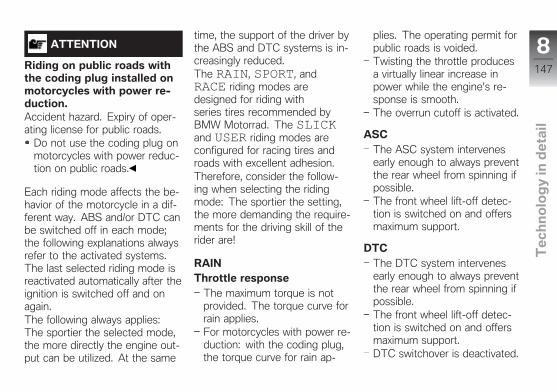
ATTENTION
Riding on public roads withthe coding plug installed onmotorcycles with power re-duction.Accident hazard. Expiry of oper-ating license for public roads.
Do not use the coding plug onmotorcycles with power reduc-tion on public roads.
Each riding mode affects the be-havior of the motorcycle in a dif-ferent way. ABS and/or DTC canbe switched off in each mode;the following explanations alwaysrefer to the activated systems.The last selected riding mode isreactivated automatically after theignition is switched off and onagain.The following always applies:The sportier the selected mode,the more directly the engine out-put can be utilized. At the same
time, the support of the driver bythe ABS and DTC systems is in-creasingly reduced.The RAIN, SPORT, andRACE riding modes aredesigned for riding withseries tires recommended byBMW Motorrad. The SLICKand USER riding modes areconfigured for racing tires androads with excellent adhesion.Therefore, consider the follow-ing when selecting the ridingmode: The sportier the setting,the more demanding the require-ments for the driving skill of therider are!
RAINThrottle response
The maximum torque is notprovided. The torque curve forrain applies.For motorcycles with power re-duction: with the coding plug,the torque curve for rain ap-
plies. The operating permit forpublic roads is voided.Twisting the throttle producesa virtually linear increase inpower while the engine's re-sponse is smooth.The overrun cutoff is activated.
ASCThe ASC system intervenesearly enough to always preventthe rear wheel from spinning ifpossible.The front wheel lift-off detec-tion is switched on and offersmaximum support.
DTCThe DTC system intervenesearly enough to always preventthe rear wheel from spinning ifpossible.The front wheel lift-off detec-tion is switched on and offersmaximum support.DTC switchover is deactivated.
8147
z Te
ch
no
log
y in
de
tail

Launch Control (L-CON) is de-activated.
ABSThe ABS system always inter-venes early enough to preventthe wheels from locking up andthe rear wheel from lifting offthe ground if possible.Maximum support for integralpressure buildup when only thehandbrake lever is actuated.ABS for rear wheel is activated.The rear wheel lift-off detectionfunction is activated.
DDCDamping adjustment: Road =comfortable dampingFine adjustment of damping ispossible with the instrumentcluster.
SPORTThrottle response
The maximum torque is pro-vided.For motorcycles with power re-duction: with the coding plug,the torque curve for maximumtorque applies. The operat-ing permit for public roads isvoided.The engine's response is opti-mal and direct.The overrun cutoff is activated.
ASCThe ASC system interveneslater than in the RAIN ridingmode so that minor drifts arepossible at the ends of curves.The front wheel lift-off detec-tion is switched on and offersmaximum support.
DTCThe DTC system interveneslater than in the RAIN riding
mode so that minor drifts arepossible at the ends of curves.The front wheel lift-off detec-tion is switched on and offersmaximum support.DTC switchover is deactivated.Launch Control (L-CON) is de-activated.
ABSThe behavior of the ABS sys-tem is comparable to that ofthe RAIN riding mode.The ABS system always inter-venes early enough to preventthe wheels from locking up andthe rear wheel from lifting offthe ground if possible.Maximum support for integralpressure buildup when only thehandbrake lever is actuated.ABS for rear wheel is activated.The rear wheel lift-off detectionfunction is activated.
8148
z Te
ch
no
log
y in
de
tail

DDCDamping adjustment: Road =comfortable dampingFine adjustment of damping ispossible with the instrumentcluster.
RACEThe RACE riding mode is thesportiest mode as long as thecoding plug is not installed.Throttle response
The maximum torque is pro-vided.For motorcycles with power re-duction: with the coding plug,the torque curve for maximumtorque applies. The operat-ing permit for public roads isvoided.The engine's response is opti-mal and direct.The overrun cutoff is activated.
ASCThe ASC system intervenesearly enough to always preventthe rear wheel from spinning ifpossible.The front wheel lift-off detec-tion is switched on and offersmaximum support.
DTCThe DTC system interveneseven later so that longer driftsand brief wheelies are alsopossible at the end of curves.The front wheel lift-off detec-tion is switched on, however itoffers only minimal support.DTC switchover is deactivated.Launch Control (L-CON) is de-activated.
ABSThe ABS system always inter-venes so early that locking ofthe wheels is avoided when-ever possible.
The ABS system interveneslater in this riding mode. Thewheels are still prevented fromlocking up, however the lift-offdetection for the rear wheel isreduced. The rear wheel canlift off the ground!Support for integral pressurebuildup is reduced.ABS for rear wheel is activated.
DDCDamping adjustment:Dynamic = sporty dampingFine adjustment of damping ispossible with the instrumentcluster.
SLICKTo activate the SLICK ridingmode, the coding plug must beused.The SLICK riding mode wasdeveloped for roads with goodvisibility and very high frictioncoefficients, as they are usually
8149
z Te
ch
no
log
y in
de
tail
found only on racetracks. Thismode also assumes that the mo-torcycle is riding with racing tiresthat have very good adhesion.Throttle response
The maximum torque is pro-vided.For motorcycles with power re-duction: with the coding plug,the torque curve for maximumtorque applies. The operat-ing permit for public roads isvoided.The engine output, increase inpower and response are de-signed for maximum sportiness.The overrun cutoff is deacti-vated.
DTCIn this riding mode the controlof the DTC system assumesthat racing tires with maxi-mum adhesion (slick tires) aremounted. Longer wheelies andwheelies at small angles are
also permitted, which meansit is possible to flip over back-ward in extreme cases!The DTC system interveneseven later so that longer driftsand brief wheelies are alsopossible at the end of curves.The front wheel lift-off detec-tion is deactivated.The DTC switchover is acti-vated.Launch Control (L-CON) is ac-tivated.
ABSThe ABS system is only oper-ative when the handbrake leveris actuated.The ABS system interveneslater in this riding mode.Although wheel locking is stillprevented, it is possible thatthe rear wheel lifts off theground.Support during integral pres-sure buildup is reduced ear-
lier than in the SPORT ridingmode.ABS for rear wheel is deac-tivated. However, if the foot-brake lever is operated, there isno more ABS regulation on therear wheel. The rear wheel canlock up.The rear wheel lift-off detectionis deactivated.
DDCDamping adjustment: Track =sporty damping for racetracksFine adjustment of damping ispossible with the instrumentcluster.
USERTo activate the USER ridingmode, the coding plug must beused.The behavior corresponds to theSLICK riding mode, howeverthe following systems can be ad-justed individually:
8150
z Te
ch
no
log
y in
de
tail

Throttle response (ENGINE)RAINRACESLICKThe following torque curvesapply for motorcycles withpower reduction and mountedcoding plug: RACE/SLICK set-ting = maximum torque, RAINsetting = torque curve for rain.The operating permit for publicroads is voided.The overrun cutoff is deacti-vated.
DTCRAINSPORTRACESLICKThe DTC switchover is acti-vated. The DTC switchover issaved separately for each DTCmode.Launch Control (L-CON) is ac-tivated.
ABSSPORTRACESLICK
DDCSPORTRACESLICK
ASC offSupport by the ASC function isdeactivated.The front wheel lift-off detec-tion is deactivated.
DTC offSupport by the DTC function isdeactivated.The front wheel lift-off detec-tion is deactivated.DTC switchover is deactivated.Launch Control (L-CON) is ac-tivated, however only the en-
gine speed limitation is effec-tive.
ABS offSupport by the ABS function isdeactivated.No support for integral pres-sure buildup when only thehandbrake lever is actuated.ABS for rear wheel is deacti-vated.The rear wheel lift-off detectionis deactivated.
Changing the settingThe switchover process for thefunctions in the engine manage-ment system, the ABS and theDTC is only possible in certainoperating modes:
No drive torque at rear wheelNo brake pressure in the brakesystem.
To stop transmission of drivetorque,
8151
z Te
ch
no
log
y in
de
tail

Motorcycle must be stoppedwith the ignition switched on
or (during riding)Throttle grip must be twistedback,Brake levers may not be actu-ated.
First the desired riding mode ispreselected. The new selectionis not activated until the specifiedconditions are present in all af-fected systems.The selection menu does notdisappear in the display until theriding mode has been switchedover.
Pro Gear ShiftAssistant
with Pro shift assistantOE
Your motorcycle is equipped witha Gear Shift Assistant originallydeveloped for racing but nowspecially adapted for use in pub-lic road traffic. It allows you up-shift and downshift under almostany load conditions and in vir-tually all engine-speed rangeswithout operating the clutch oraccelerator.Benefits
70-80 % of all gear changescan be performed without us-ing the clutch.Less movement between pilotand pillion due to shorter gear-change intervals.Throttle does not have to beclosed when changing gearunder acceleration.During deceleration and down-shifts (throttle plate closed) thesystem blips the throttle to ob-tain the correct engine speed.
Shifting times are faster thanwhen the clutch is used tochange gears.
For the system to detect the rid-er's intention to change gear, thegear lever previously not oper-ated must be moved against theforce of the spring by a certainamount of "overtravel" in the de-sired direction with a normal tobrisk action and held in that po-sition until the gear change iscompleted. A further increaseof the force applied to the gearlever during the gear-shift op-eration is not necessary. Afterthe gear change is completed,the gear lever must be fully re-leased before the Gear Shift As-sistant Pro can execute a newgear change. When changinggear using the gear-shift assis-tance function, the throttle set-ting (twist-grip position) must bekept constant before and dur-ing the gear-change sequence.
8152
z Te
ch
no
log
y in
de
tail

Changing the accelerator twist-grip position during the gear-shift sequence may cause thefunction to abort and/or the gearchange to fail. No support is pro-vided by the Gear Shift Assistantduring gear changes made usingthe clutch.Downshifts
Downshifts are assisted up tothe speed at which the enginereaches maximum rpm in thegear to be engaged. Over-revving is thus prevented.
Maximum engine speed
max 14200 min-1
UpshiftsThe Gear Shift Assistant doesnot provide added supportwhen the engine speed wouldfall below idle in the new gear.
Idle speed
1250 min-1 (Engine at operat-ing temperature)
8153
z Te
ch
no
log
y in
de
tail

8154
z Te
ch
no
log
y in
de
tail
Maintenance
General instructions . . . . . . . . . . . . . . . . 156
Onboard tool kit . . . . . . . . . . . . . . . . . . . 156
Front wheel stand . . . . . . . . . . . . . . . . . 157
Rear-wheel stand . . . . . . . . . . . . . . . . . . 158
Engine oil . . . . . . . . . . . . . . . . . . . . . . . . . . 159
Brake system . . . . . . . . . . . . . . . . . . . . . . 161
Clutch . . . . . . . . . . . . . . . . . . . . . . . . . . . . . 165
Coolant . . . . . . . . . . . . . . . . . . . . . . . . . . . . 166
Tires . . . . . . . . . . . . . . . . . . . . . . . . . . . . . . . 167
Wheel rims and tires . . . . . . . . . . . . . . . 168
Wheels . . . . . . . . . . . . . . . . . . . . . . . . . . . . 168
Light sources . . . . . . . . . . . . . . . . . . . . . . 176
Fairings and panels . . . . . . . . . . . . . . . . 183
Jump-starting . . . . . . . . . . . . . . . . . . . . . . 184
Battery . . . . . . . . . . . . . . . . . . . . . . . . . . . . . 185
Fuses . . . . . . . . . . . . . . . . . . . . . . . . . . . . . . 188
Chain . . . . . . . . . . . . . . . . . . . . . . . . . . . . . . 189
9155
z Ma
inte
na
nc
e

General instructionsThe 'Maintenance' chapter de-scribes work involving the check-ing and replacement of wearparts that can be performed witha minimum of effort.If special tightening torques areto be taken into account forassembly, these are listed. Anoverview of all required tighteningtorques is contained in thechapter "Technical Data".Information on additional main-tenance and repair work is pro-vided in the Repair Manual foryour motorcycle on DVD, whichyou can obtain from your autho-rized BMW Motorrad retailer.
Special tools and thorough spe-cialized knowledge are requiredto carry out some of the workdescribed here. If you are indoubt, consult an authorizedworkshop, preferably your au-thorized BMW Motorrad retailer.
Onboard tool kit
1 Hook wrenchwithout Dynamic Damp-ing Control (DDC) OE
Adjusting spring preloadat rear wheel ( 70).
2 Reversible screwdriver in-sertPhillips PH1 and Torx T25
Removing and installingbody panels.Removing rider`s seat( 63).Replacing front andrear turn indicator lightsources ( 180).
3 Open-ended wrenchWrench size: 17 mm
without Dynamic Damp-ing Control (DDC) OE
Adjust spring preload onfront wheel ( 68).with Dynamic DampingControl (DDC) OE
Adjust spring preload onfront wheel ( 69).
4 Open-ended wrenchWrench size: 10/13
Removing battery( 187).with Dynamic DampingControl (DDC) OE
Adjusting spring preloadat rear wheel ( 71).
5 Reversible screwdriver withPhillips and straight blade
without Dynamic Damp-ing Control (DDC) OE
Adjust compressiondamping on front wheel( 72).
9156
z Ma
inte
na
nc
e

5 without Dynamic Damp-ing Control (DDC) OE
Rebound-stage dampingon front wheel ( 73).without Dynamic Damp-ing Control (DDC) OE
Adjusting rebound-stagedamping at rear wheel( 74).without Dynamic Damp-ing Control (DDC) OE
Adjusting compressiondamping (jounce) at rearwheel ( 74).
6 Spare fuses with gripperMiniature fuses, 4 A, 7.5 Aand 10 A
Puller for removing fusesReplacement fuses
7 Plastic attachmentwith Dynamic DampingControl (DDC) OE
Adjust spring preload onfront wheel ( 69).
8 TORX wrench, T25
8 Removing and installingbody panels.Removing rider`s seat( 63).
Front wheel standInstalling the auxiliarystand on the front wheel
ATTENTION
Use of the BMW Motorradfront wheel stand without anadditional center or auxiliarystand.Component damage caused bytipping over.
Place the motorcycle on thecenter stand or an auxiliarystand before lifting it with theBMW Motorrad front wheelstand.
Place motorcycle on an auxil-iary stand; BMW Motorrad rec-
ommends the BMW Motorradauxiliary stand.Mounting rear-wheel stands( 158).
Use basic stand (83 30 0 402241) with mounting pieces (8330 2 152 839).
9157
z Ma
inte
na
nc
e

Insert the service adapter (8330 2 152 840) 1 at the left andright into the front suspension.
Turn in the bracket 2 with thelong sides facing the inside.Adjust the mounting pieces 3to the width of the service
adapter inserted into the frontsuspension.Adjust the height of the aux-iliary stand so that the frontwheel is lifted slightly off theground.
Attach the auxiliary stand to thefront suspension and press iton the ground evenly.
Rear-wheel standMounting rear-wheelstands
Use basic stand with part num-ber (83 30 0 402 241) and themounting pieces (83 30 2 152839).
9158
z Ma
inte
na
nc
e

Install the service adapter (8330 2 152 841) 1 on the leftand right into the rear wheelswinging arm, tightening tospecified torque.
Swinging-arm adapter onrear wheel swinging arm
15 lb/ft (20 Nm)
Turn in the bracket 2 with thelong sides facing the outside.Adjust the mounting pieces 3to the width of the serviceadapter inserted into the frontsuspension.Adjust the height of the rearwheel stand so that the rearwheel is lifted slightly off theground.
Attach the rear wheel stand tothe rear wheel swing arm andpress it on the ground evenly.
Engine oilCheck engine oil level
ATTENTION
The oil level varies with thetemperature of the oil. Thehigher the temperature, thehigher the level of oil in thesump.Misinterpretation of the oil capac-ity
9159
z Ma
inte
na
nc
e

Only check the oil level aftera longer journey or when theengine is warm.
Make sure ground is level andfirm and hold motorcycle at op-erating temperature vertically.Allow engine to run in neutralfor one minute.Switch off ignition.
Read oil level in display 1.
Specified level of engineoil
between MIN- and MAX mark
Engine oil, capacity
SAE 5W-40, API SL/JASO MA2, Additives (forinstance, molybdenum-basedsubstances) are prohibited,because they would attackthe coatings on enginecomponents, BMW Motorradrecommends BMW MotorradADVANTEC Ultimate Oil
Engine oil, capacity
Approx. 3.7 quarts (Approx.3.5 l) (with filter replacement)
If oil level is below minimummark:
Top up engine oil ( 160).
If oil level is above maximummark:
Have oil level corrected atan authorized service facility,preferably an authorizedBMW Motorrad retailer.
Topping up engine oilPark motorcycle, ensuring thatsupport surface is firm andlevel.Wipe area around oil fill loca-tion to clean it.
9160
z Ma
inte
na
nc
e

Remove cap 1 of oil fill loca-tion.
ATTENTION
Too little or too much engineoil.Engine damage
Always make sure that the oillevel is correct.
Add engine oil up to specifiedlevel.Check engine oil level ( 159).Install cap of oil fill location 1.
Brake systemCheck brake operation
Operate the brake lever.Pressure point must be clearlyperceptible.Actuate the footbrake lever.Pressure point must be clearlyperceptible.
If no clear pressure points areperceptible:
ATTENTION
Improper working on thebrake system.Endangering of the operatingsafety of the brake system.
Have all work on the brake sys-tem carried out by experts.
Have the brakes checked at anauthorized workshop, preferablyan authorized BMW Motorradretailer.
Checking front brake padthickness
Park motorcycle, ensuring thatsupport surface is firm andlevel.Turn handlebars.
Visually inspect left and rightbrake pads to determine theirthickness. Direction of view:From rear looking at brakepads 1.
9161
z Ma
inte
na
nc
e

Front brake-pad wearlimit
min 0.03 in (min 0.8 mm)(Only friction material withoutcarrier plate)
If brake pads are worn:
WARNING
Dropping below the minimumpad thickness.Reduced braking action. Damageto the brake.
In order to ensure the operat-ing reliability of the brake sys-tem, make sure that the brake
pads are not worn beyond theirminimum thickness.
Have brake pads replaced atan authorized service facil-ity, preferably an authorizedBMW Motorrad retailer.
If genuine BMW Motorradbrake pads are not installed,be sure to check thickness ofbrake-pad carrier plate.
Thickness of brake-padcarrier plate
min 0.18 in (min 4.5 mm)
If carrier plate thickness is insuffi-cient:
WARNING
Use of unsuitable brakepads.Failure of the brake system dueto loss of the brake pads.
Only use brake pads with acarrier plate with a thickness ofat least 0.18 in (4.5 mm).
BMW Motorrad recommendsinstalling only genuineBMW Motorrad brake pads.
Check rear brake padthickness
Make sure ground is level andfirm and park motorcycle.
9162
z Ma
inte
na
nc
e

Conduct a visual inspection ofthe brake pad thickness. Direc-tion of view: From rear lookingat brake pads 1.
Rear brake-pad wearlimit
min 0.04 in (min 1.0 mm)(Only friction material withoutcarrier plate.)
If the wear indicating mark is nolonger visible:
WARNING
Dropping below the minimumpad thickness.Reduced braking action. Damageto the brake.
In order to ensure the operat-ing reliability of the brake sys-
tem, make sure that the brakepads are not worn beyond theirminimum thickness.
Have the brake pads replacedat an authorized service facil-ity, preferably an authorizedBMW Motorrad retailer.
Checking front brake fluidlevel
Make sure ground is level andfirm and hold motorcycle verti-cally.Move handlebars into straight-ahead position.
9163
z Ma
inte
na
nc
e

Read off brake fluid level atbrake-fluid reservoir 1.
NOTICE
The brake fluid level in the brake-fluid reservoir drops due to brakepad wear.
Front brake fluid level
Brake fluid, DOT4
The brake fluid level mustnot fall below the MIN mark.(Brake-fluid reservoir horizon-tal)
If brake fluid level falls below theapproved level:
WARNING
Insufficient brake fluid in thebrake-fluid reservoir.
Considerably reduced brakingperformance caused by air in thebrake system.
Check brake fluid levelregularly.
Have the defect corrected assoon as possible by an autho-rized workshop, preferably anauthorized BMW Motorrad re-tailer.
Checking rear brake fluidlevel
Make sure ground is level andfirm and hold motorcycle verti-cally.
9164
z Ma
inte
na
nc
e

Check level of brake fluid inrear brake-fluid reservoir 1.
NOTICE
The brake fluid level in the brake-fluid reservoir drops due to brakepad wear.
Rear brake fluid level
Brake fluid, DOT4
The brake fluid level mustnot fall below the MIN mark.(Brake-fluid reservoir horizon-tal)
If brake fluid level falls below theapproved level:
WARNING
Insufficient brake fluid in thebrake-fluid reservoir.
Considerably reduced brakingperformance caused by air in thebrake system.
Check brake fluid levelregularly.
Have the defect corrected assoon as possible by an autho-rized workshop, preferably anauthorized BMW Motorrad re-tailer.
ClutchCheck clutch function
Pull back the clutch lever.Pressure point must be clearlyperceptible.
If no clear pressure point can befelt:
Have the clutch checked by anauthorized workshop, preferablyan authorized BMW Motorradretailer.
9165
z Ma
inte
na
nc
e

Checking clutch lever play
Operate clutch lever 1 untilresistance is felt.Measure clutch play A be-tween handlebar fitting andclutch lever in this position.
Clutch lever play
0.02...0.04 in (0.5...1.0 mm)(on the handlebar fitting, whenthe engine is cold)
If clutch pedal free play is outsidetolerance:
Adjusting clutch lever play( 166).
Adjusting clutch leverplay
To increase clutch play: turnthe screw 2 into handlebar fit-ting.To decrease clutch play: turnthe screw 2 out of handlebarfitting.Checking clutch lever play( 166).Repeat these operations untilthe clutch play is correctly ad-justed.
CoolantChecking coolant level
Make sure ground is level andfirm and park motorcycle.
Read off coolant level on ex-pansion tank 1. Direction ofview: from front looking at in-side of right-hand side panel.
9166
z Ma
inte
na
nc
e

Coolant, specified level
between MIN and MAX markson the expansion tank (Withcold engine)
If coolant level drops below per-missible level:
Add coolant.
Topping up coolantRemove fairing side panel( 183).
Open cap 1 of expansion tank.Add coolant up to specifiedlevel.Checking coolant level( 166).Close cap of expansion tank.
Installing fairing side panel( 184).
TiresChecking tire pressure
WARNING
Incorrect tire inflation pres-sure.
Poorer handling characteristic ofthe motorcycle. Reduced life oftires.
Ensure proper tire inflationpressure.
WARNING
Valve inserts open of theirown accord at high speeds.Sudden loss of tire inflation pres-sure.
Use valve caps with rubbersealing ring and screw onfirmly.
Park motorcycle, ensuring thatsupport surface is firm andlevel.Check tire pressures againstdata below.
Tire pressure, front
36.3 psi (2.5 bar) (with tirecold)
9167
z Ma
inte
na
nc
e

Tire pressure, rear
42.1 psi (2.9 bar) (with tirecold)
If tire pressure is too low:Correct tire pressure.
Wheel rims and tiresCheck wheel rims
Make sure ground is level andfirm and park motorcycle.Subject wheel rims to visualinspection for defects.Have damaged rims checkedand, if necessary, replacedby a specialist service facil-ity, preferably an authorizedBMW Motorrad retailer.
Checking tire tread depth
WARNING
Riding with heavily worntyres
Risk of accident due to poorerrideability
If necessary, replace the tyresbefore the legally specifiedminimum tread depth isreached.
Make sure ground is level andfirm and park motorcycle.Measure tire tread depth inmain tread grooves with wearindicating marks.
NOTICE
Tread wear marks are integratedinto the main grooves on everytire. If the tire tread has worndown to the level of the marks,the tire is completely worn. Thelocations of the marks are indi-cated on the edge of the tire, e.g.by the letters TI, TWI or by anarrow.
When the minimum tread depthis reached:
Replace tires concerned.
WheelsTire recommendationFor every size of tire,BMW Motorrad has tested andapproved certain makes asroadworthy. BMW Motorradcannot evaluate the suitability ofother tires, and can thereforetake no responsibility for theirdriving safety.BMW Motorrad recommendsonly using the tires tested andapproved by BMW Motorrad.Detailed information can beobtained from your authorizedBMW Motorrad retailer or onlineat "www.bmw-motorrad.com".
9168
z Ma
inte
na
nc
e

Affect of wheel sizeson suspension controlsystemsThe wheel sizes play a major rolein the ASC and DTC suspension-control systems. The diameterand width of the wheels storedin the control unit have particularsignificance as the basis for allnecessary calculations. A changein these sizes resulting from con-version to wheels not installedas standard equipment can seri-ously affect the control efficiencyof these systems.The sensor rings required forwheel speed detection must alsomatch the installed control sys-tems and may not be replaced.If you want to equip yourmotorcycle with different wheels,please contact a specialistservice facility, preferably aBMW Motorrad retailer. In somecases the data stored in the
control units must be adapted tothe new wheel sizes.
Removing front wheelPark motorcycle, ensuring thatsupport surface is firm andlevel.
Remove screw 1 and takewheel speed sensor out ofbore.Mask off areas of wheel rimthat could be scratched in theprocess of removing the brakecalipers.
ATTENTION
Pressing together the brakepads with the brake caliperremoved.The brake caliper cannot bemounted over the brake disc.
Do not operate the brakelever with the brake caliperremoved.
Remove screws 1 of brakecalipers on left and right.
9169
z Ma
inte
na
nc
e

Push brake pads 3 slightlyapart by turning brake caliper 4back and forth against brakerotor 5.Carefully pull brake calipersback and outward to removethem from the brake rotors.
Place motorcycle on an auxil-iary stand; BMW Motorrad rec-ommends the BMW Motorradrear wheel stand.Mounting rear-wheel stands( 158).Raise front of motorcycle untilthe front wheel can turn freely.BMW Motorrad recommends
the BMW Motorrad front wheelstand for lifting the motorcycle.Installing the auxiliary stand onthe front wheel ( 157).
ATTENTION
Incorrect spacing betweenthe sensor ring and wheelspeed sensor caused bypoorly aligned threadedbushing in the frontsuspension.Damage to the wheel speed sen-sor. ABS malfunction.
The left clamp fixes thethreaded bushing in position
and must not be loosened orremoved.
Loosen clamping screws 2.Remove quick-release axle 1while supporting wheel.Roll front wheel forward to re-move it.
Installing front wheel
WARNING
Use of a wheel which doesnot comply with series speci-fications.Malfunctions during control inter-ventions by ABS and DTC.
Please see the information onthe effect of wheel sizes on theABS and DTC chassis controlsystems at the beginning ofthis chapter.
9170
z Ma
inte
na
nc
e

ATTENTION
Tightening of screwed con-nections with incorrect tight-ening torque.Damage or loosening of screwedconnections.
Always have the tighteningtorques checked by a spe-cialized workshop, preferablyan authorized BMW Motorradretailer.
ATTENTION
Front wheel installation op-posite the running direction.Accident hazard
Observe running direction ar-rows on tire or rim.
Roll front wheel into frontsuspension.
Lift front wheel and installquick-release axle 1 withtorque.
Quick-release axle inthreaded bush
37 lb/ft (50 Nm)
Tighten clamping screws 2 tospecified torque.
Clamping screw in axleadapter
Tightening sequence: Tightenthe screws 6 times, alternatingbetween one and the othereach time
14 lb/ft (19 Nm)
Remove front wheel stand andauxiliary stand.
Slide the brake calipers ontothe brake rotors.
9171
z Ma
inte
na
nc
e

Lay on brake caliper 1 on leftand position cable guide 2.Install screws 3 with specifiedtorque.
Radial brake calipers onthe axle adapter
28 lb/ft (38 Nm)
Fasten cable for wheel speedsensor in bracket (arrow).
Insert wheel speed sensor inbore and fasten with screw 1.
Lay on brake caliper 1 on rightand install screws 2 with speci-fied torque.
Radial brake calipers onthe axle adapter
28 lb/ft (38 Nm)
Remove adhesive tape fromwheel rim.Operate the brake lever firmlyseveral times, until the pressurepoint is felt.
Removing rear wheelRaise motorcycle, preferablywith a BMW Motorrad rear-wheel stand.Mounting rear-wheel stands( 158).Support the rear wheel, e.g.,with a wooden block, so thatit cannot fall down after thequick-release axle is removed.
9172
z Ma
inte
na
nc
e

Press brake caliper 1 againstbrake disk 2.Brake pistons are pressedback.
Remove axle nut 1 withwasher.
Loosen lock nuts 2 on left andright.Loosen adjusting screws 3 onleft and right.Remove adjusting plate 4 andslide axle as far as possible to-ward inside.
Remove quick-release axle 2and take out adjusting plate 1.
Roll rear wheel as far forwardas possible and removechain 1 from chain sprocket.
Remove screw 1 and detachbrake line from bracket 2.
9173
z Ma
inte
na
nc
e

Make sure that the wheelspeed sensor 1 is notdamaged when rolling out therear wheel.
Roll rear wheel toward rearout of swing arm while pullingbrake caliper carrier 1 toward
rear until rear-wheel rim can beguided past it.
NOTICE
The chain sprocket and thespacer sleeves on the left andright are loosely inserted in thewheel. Exercise care during theremoval, in order that the partsare not damaged or are lost.
Install rear wheel
ATTENTION
Altering the tire size.Influence on the control systems.
When converting the rear tiresize from 190 ⁄ 55 ZR 17 to200 ⁄ 55 ZR 17 or vice versa,the parameters of the controlsystems must be encoded bya BMW authorized workshop,preferably by a BMW Motorradretailer.
ATTENTION
Tightening of screwed con-nections with incorrect tight-ening torque.Damage or loosening of screwedconnections.
Always have the tighteningtorques checked by a spe-cialized workshop, preferablyan authorized BMW Motorradretailer.
Roll rear wheel on support intoswing arm until brake-calipersupport can be installed.
9174
z Ma
inte
na
nc
e

Mount brake caliper carrier 1 inguide 2.
Make sure that the wheelspeed sensor 1 is notdamaged when rolling the rearwheel into place.
Roll rear wheel further intoswing arm while simultaneouslypushing brake caliper carrier 1toward the front.
Roll rear wheel as far forwardas possible and lay chain 1 onsprocket.
Insert right-hand adjustingplate 1 in swinging arm.Raise the rear wheel and in-stall the quick-release axle 2
9175
z Ma
inte
na
nc
e

through the shim in the brake-caliper support and the rearwheel.Make sure that quick-releaseaxle meets the recess for keysurfaces.
Mount adjusting plate on left 1.Install axle nut 2 with washer,however do not tighten yet.
Fasten brake line in holder 2and install screw 1.
Adjusting chain tension( 190).
Light sourcesReplacing light sourcesfor low-beam and high-beam headlight
NOTICE
The alignment of the connectormay differ from the illustrationdepending on the light source tobe replaced.
Park motorcycle, ensuring thatsupport surface is firm andlevel.Switch off ignition.
Remove cover 1 to replacelight source for low-beamheadlight.
9176
z Ma
inte
na
nc
e

Remove the cover 2 to replacethe light source for the high-beam headlight.
Disconnect plug 3.
Release wire spring 4 fromcatch on left and right and foldup.Remove light source 5 fromthe socket.
Replace defective light source.
NOTICE
Light sources featuring spec-ification ratings for higher lev-els of illumination are commer-cially available as special acces-sories. These light sources havea shorter service life than con-ventional light sources and alsogenerate more heat. Under some
circumstances the high levels ofheat radiation can damage theheadlight assembly.
Bulbs for low-beamheadlight
H7 / 12 V / 55 W
Bulb for high-beamheadlight
H7 / 12 V / 55 W
To protect the glass againstsoiling, only grasp the lightsource by the base.
9177
z Ma
inte
na
nc
e

Install light source 5. Start byinserting lug 6, then press lightsource into socket.Insert both sides of wirespring 4 into the retainer.
Connect plug 3.
Install cover.
Replacing light source forleft-hand parking light
Park motorcycle, ensuring thatsupport surface is firm andlevel.Switch off ignition.
Remove cover 1.
Push the retainer 2 downward(using a screwdriver if nec-essary) and pull the socket 3from the headlight housing.
Remove light source 4 fromthe socket.
9178
z Ma
inte
na
nc
e

Replacing defective lightsource.
Bulb for parking light
W5W / 12 V / 5 W
To prevent dirt from being de-posited on the glass surface,always use a clean, dry cloth tohold the light source.
Insert light source 4 in lightsource socket.
Insert socket 3 in the head-light housing such that the re-tainer 2 engages.Install the cover.
Replacing right-handparking light light source
Park motorcycle, ensuring thatsupport surface is firm andlevel.Switch off ignition.
Remove cover 1.
Push the retainer 2 downward(using a screwdriver if nec-essary) and pull the socket 3from the headlight housing.
9179
z Ma
inte
na
nc
e

Remove light source 4 fromthe socket.
Replacing defective lightsource.
Bulb for parking light
W5W / 12 V / 5 W
To prevent contaminants frombeing deposited on the glasssurface, always use a clean, drycloth to hold the light source.
Insert light source 4 in lightsource socket.
Insert socket 3 in headlighthousing, continuing to applypressure until the retainer 2engages.
Install the cover.
Replacing front andrear turn indicator lightsources
Park motorcycle, ensuring thatsupport surface is firm andlevel.Switch off ignition.
Remove the screw 1.
9180
z Ma
inte
na
nc
e

Pull glass on screw connectionside out of mirror housing.
Remove the light source 2from the light housing bypressing it in and turning itcounterclockwise.
Replace defective light source.
Bulbs for flashing turnindicators, front
RY10W / 12 V / 10 W
Bulbs for flashing turnindicators, rear
RY10W / 12 V / 10 W
To prevent dirt from being de-posited on the glass surface,always use a clean, dry cloth tohold the light source.
Install the light source 2 in thelight housing by pressing it inand turning it clockwise.
Insert inside end of lens intolight housing and close it.
9181
z Ma
inte
na
nc
e

Fit the screw 1.
Diode taillightIf the taillight LEDs have failed,the taillight must be replaced. Inthis case:
Contact an authorized servicefacility, preferably an authorizedBMW Motorrad retailer.
Replace license plate light
Pull license-plate light 1 out oflight housing.
Remove light source fromsocket.
Replace defective light source.
Bulb for license-platelight
W5W / 12 V / 5 W
To prevent contaminants frombeing deposited on the glasssurface, always use a clean, drycloth to hold the light source.
Press light source into socket.
9182
z Ma
inte
na
nc
e

Press license-plate light 1 intolight housing.
Fairings and panelsRemove fairing side panel
NOTICE
The working steps describedhere for the right fairing sidepanel also apply logically for theleft side.
Park motorcycle, ensuring thatsupport surface is firm andlevel.
Remove screw 1 on inside offairing side panel.
Remove screws 2.Detach fairing side panel fromgrommet 3 and detent pin 4.
Disconnect connector 5 forturn indicator.Take off fairing side panel.Protect connector on motorcy-cle 6 against soiling.
9183
z Ma
inte
na
nc
e

Installing fairing sidepanel
Mount fairing side panel 7 inmount 8 on engine spoiler.
Insert connector 5 in connec-tor 6.
Fasten fairing side panel ingrommet 3 and detent pin 4.Install screws 2.
Install screw 1.
Jump-starting
CAUTION
Touching live parts of the ig-nition system when the en-gine is running.Electrocution
Do not touch parts of the igni-tion system when the engine isrunning.
ATTENTION
Current too high when jump-starting the motorcycleCable fire or damage to the vehi-cle electronics
Do not jump-start the motor-cycle using the power socket,only via the battery terminal.
ATTENTION
Contact between crocodileclips of jump leads and mo-torcycle.
9184
z Ma
inte
na
nc
e

Danger of short circuitUse jump leads fitted with fullyinsulated crocodile clips at bothends.
ATTENTION
Jump-starting with a voltagehigher than 12 V.Damage to the motorcycle'selectronics.
The battery of the donor mo-torcycle must have a voltage of12 V.
Do not disconnect battery fromonboard electrical system forjump-starting procedure.Removing rider`s seat ( 63).Allow engine on support mo-torcycle to run while jump-starting.Begin by clamping one end ofthe red jumper cable to thepositive terminal of the dis-charged battery and clamping
the other end to the positiveterminal of the donor battery.Then clamp one end of theblack jumper cable to thedonor battery's negativeterminal while connectingthe other end to dischargedbattery's negative terminal.Start engine of motorcycle withdischarged battery in usualway; if engine does not start,wait a few minutes before re-peating attempt in order to pro-tect starter motor and donorbattery.Allow both engines to idle for afew minutes before disconnect-ing jumper cables.Disconnect jumper cable fromnegative terminals first, thendisconnect second cable frompositive terminals.Installing driver's seat ( 63).
BatteryMaintenance instructionsCorrect upkeep, recharging andstorage will prolong the life ofthe battery and are essential forrecognition of warranty claims.Compliance with the points be-low is important in order to maxi-mize battery life:
Keep the surface of the batteryclean and dryDo not open the batteryDo not top up with waterBe sure to read and complywith the instructions for charg-ing the battery on the followingpagesDo not turn the battery upsidedown.
ATTENTION
Discharging of the connectedbattery by the vehicle elec-tronics (e.g. clock).
9185
z Ma
inte
na
nc
e

Total discharge of battery leadingto a rejection of warranty claims.
During riding breaks of morethan 4 weeks, connect atrickle-charger to the battery.
NOTICE
BMW Motorrad has developed atrickle-charger specially designedfor compatibility with the elec-tronics of your motorcycle. Usingthis charger, you can keep thebattery charged during long pe-riods when the motorcycle is notbeing used without having to dis-connect the battery from the mo-torcycle's onboard systems. Ad-ditional information is available atyour authorized BMW Motorradretailer.
Disconnect battery frommotorcycle
Park motorcycle, ensuring thatsupport surface is firm andlevel.Removing rider`s seat ( 63).
ATTENTION
Incorrect battery disconnec-tion.Danger of short circuit
Follow the disconnectionsequence.
First remove negative batterycable 1.Then remove positive batterycable 2.
with anti-theft alarm system(DWA)OE
ATTENTION
Incorrect battery disconnec-tion.Danger of short circuit
Follow the disconnectionsequence.
First remove negative batterycable 1.
9186
z Ma
inte
na
nc
e

Then remove positive batterycable 2.
Connect battery to vehicle
First install positive battery ca-ble 2.Then install negative batterycable 1.
with anti-theft alarm system(DWA)OE
First install positive battery ca-ble 2.Then install negative batterycable 1.
Installing driver's seat ( 63).
Charging batteryDisconnect battery from motor-cycle ( 186).Charge battery using a suitablecharger.Comply with operating instruc-tions of charger.
Once battery is fully charged,disconnect charger's terminalclips from battery terminals.
NOTICE
In the case of longer periodswhen the motorcycle is not be-ing used, the battery must berecharged regularly. See theinstructions for caring for yourbattery. Always fully rechargethe battery before returning it touse.
Connect battery to vehicle( 187).
Removing batteryRemoving rider`s seat ( 63).Disconnect battery from motor-cycle ( 186).Lift battery upwards; if it is dif-ficult to move, moving it backand forth will help.
9187
z Ma
inte
na
nc
e

Install battery
NOTICE
If the motorcycle wasdisconnected from the batteryfor a longer time, the currentdate must be entered in theinstrument cluster to ensure theproper operation of the servicedisplay.Consult a certified service fa-cility, preferably an authorizedBMW Motorrad retailer, for set-ting of the date.
Place battery in battery com-partment, positive terminal onright in direction of travel.Place battery in battery com-partment with negative terminalon left in driving direction.Connect battery to vehicle( 187).
Installing driver's seat ( 63).Set clock ( 50).
FusesRemoving fuse
ATTENTION
Bypassing defective fuses.Risk of short circuit and fire.
Replace defective fuses withnew fuses.
Switch off ignition.Park motorcycle, ensuring thatsupport surface is firm andlevel.Remove passenger seat( 62).
Press together locking leverand remove cover of fusebox 1.To replace main fuse, removecover 2.Pull defective fuse upward outof fuse box.
NOTICE
If the fuses blow frequently, havethe electrical system checked byan authorized specialized work-shop, preferably an authorizedBMW Motorrad retailer.
9188
z Ma
inte
na
nc
e

Installing fuse
Replace defective fuse withfuse with required amperage.
NOTICE
An overview of the fuse assign-ment and the required amper-ages is provided in the chapter"Technical Data". The numbersin the graphic match the fusenumbers.
Close fuse cover.Locking device audibly en-gages.Install the passenger seat( 62).
ChainLubricate chain
ATTENTION
Insufficient cleaning and lu-brication of the drive chain.Increased wear.
Clean and lubricate the drivechain regularly.
Lubricate drive chain at leaseevery 500 mls (800 km). Afterdriving though water or dustand dirt perform the lubricationat shorter intervals.Switch off ignition and engageNeutral.Clean drive chain with suitablecleaning agent, dry and applychain lubricant.To extend and maximizethe chain's service lifeBMW Motorrad recommendsusing BMW Motorrad chainlubricant or:
Lubricant
Chain spray
Wipe off excess lubricant.
Checking chain tensionPark motorcycle, ensuring thatsupport surface is firm andlevel.Turn the rear wheel until theposition with the lowest chainsag is reached.
Using a screwdriver, push thechain in the middle between
9189
z Ma
inte
na
nc
e

the pinion and sprocket andmeasure the difference A.
Chain sag
1.8...2 in (45...50 mm) (Motor-cycle unloaded on side stand)
If the measured value is outsidethe approved tolerance:
Adjusting chain tension( 190).
Adjusting chain tensionMake sure ground is level andfirm and park motorcycle.
Loosen quick-release axlenut 1.Loosen lock nuts 3 on left andright.Adjust chain tension with ad-justing screws 2 on left andright.Checking chain tension( 189).Ensure that the figures 4 indi-cating the adjustment settingsare identical on left and right.Tighten locknuts 3 on left andright to the specified torque.
Locknut of drive-chaintensioning screw
14 lb/ft (19 Nm)
Tighten quick-release axlenut 1 to specified torque.
Rear-wheel quick-releaseaxle in swinging arm
Thread-locking compound:mechanical
74 lb/ft (100 Nm)
Checking chain wearEngage 1st gear.Rotate rear wheel toward frontof vehicle until the chain is ten-sioned.Determine chain length belowrear wheel swinging arm.
9190
z Ma
inte
na
nc
e

Permissible chain length
max 5.7 in (max 144.30 mm)(Measured over the center of10 rivets, chain tensioned)
If the chain has reached the max-imum approved length:
Contact an authorized servicefacility, preferably an authorizedBMW Motorrad retailer.
9191
z Ma
inte
na
nc
e

9192
z Ma
inte
na
nc
e
Accessories
General instructions . . . . . . . . . . . . . . . . 19410193
z Ac
ce
sso
rie
s

General instructionsBMW Motorrad recommendsthe use of parts and accessoriesfor your motorcycle that are ap-proved by BMW for this purpose.Your authorized BMW Motorradretailer is the right place to gofor genuine BMW parts and ac-cessories,other BMW approvedproducts, and expert advice ontheir installation and use.These parts and products havebeen tested by BMW for safety,function and suitability. BMWaccepts product liability for theseproducts.Conversely, BMW is unable toaccept any liability whatsoeverfor parts and accessories which ithas not approved.Observe the information on theimportance of tire sizes for chas-sis control systems ( 169).
CAUTION
Use of products from othermanufacturers.Safety risk
BMW Motorrad cannot exam-ine or test each product of out-side origin to ensure that it canbe used on or in connectionwith BMW motorcycles withoutconstituting a safety hazard.Nor is this guarantee providedwhen the official approval ofa specific country has beengranted. Tests conducted bythese instances cannot makeprovision for all operating con-ditions experienced by BMWmotorcycles and, consequently,they are not sufficient in somecircumstances.Use only parts and accessoriesapproved by BMW for yourmotorcycle.
Whenever you are planning mod-ifications, comply with all the le-gal requirements. The motorcy-cle must not infringe on nationalroad-motorcycle construction anduse regulations of your country.
10194
z Ac
ce
sso
rie
s

Care
Care products . . . . . . . . . . . . . . . . . . . . . 196
Washing your motorcycle . . . . . . . . . . 196
Cleaning sensitive motorcycleparts . . . . . . . . . . . . . . . . . . . . . . . . . . . . . . . 197
Paint care . . . . . . . . . . . . . . . . . . . . . . . . . . 197
Store motorcycle . . . . . . . . . . . . . . . . . . 198
Protective wax coating . . . . . . . . . . . . . 198
Return motorcycle to use . . . . . . . . . . 198
11195
z Ca
re

Care productsBMW Motorrad recommendsthat you use cleaning andcare products available at yourauthorized BMW Motorradretailer. BMW CareProductshave been materials tested,laboratory tested, and field testedand provide optimum care andprotection for the materials usedin your motorcycle.
ATTENTION
Use of unsuitable cleaningand care agents.Damage to motorcycle parts.
Do not use any solvents suchas nitro thinners, cold cleaners,fuel or similar, and do not usecleaning agents that containalcohol.
Washing yourmotorcycleBMW Motorrad recommendsthat you use BMW Insect Re-mover to soften and wash offinsects and stubborn dirt frompainted parts before washing themotorcycle.To prevent stains, do not washthe motorcycle immediately afterit has been exposed to brightsunlight and do not wash it in thesun.Make sure that the motorcycleis washed frequently, especiallyduring the winter months.To remove road salt, clean themotorcycle with cold water im-mediately after completion of ev-ery trip.
WARNING
Damp brake disks and brakepads after washing the mo-
torcycle, after riding throughwater or in the rain.Poorer braking action.
Brake early until the brake ro-tors and brake pads are dry.
ATTENTION
Increased effect of saltcaused by warm water.Corrosion
Only use cold water to removeroad salt.
ATTENTION
Damage caused by high wa-ter pressure from high-pres-sure cleaners or steam-jetdevices.Corrosion or short-circuit, dam-age to seals, to hydraulic brakesystem, to the electrical systemand the seat.
11196
z Ca
re

Exercise caution when usinghigh-pressure or steam-jetdevices.
Cleaning sensitivemotorcycle partsPlastics
ATTENTION
Use of unsuitable cleaningagents.Damage to plastic surfaces.
Do not use abrasive cleaners orcleaners containing alcohol orsolvents.Do not use insect sponges orsponges with a hard surface.
Fairings and panelsClean body panels with waterand BMW plastic cleaner.
Windshields and lenses aremanufactured in plasticClean off dirt and insects with asoft sponge and plenty of water.
NOTICE
Soften stubborn dirt and deadinsects by covering the affectedareas with a wet cloth.
ChromeEspecially in the case of roadsalt, carefully clean chrome partswith plenty of water and BMWauto shampoo. Use chrome pol-ish for additional treatment.
RadiatorClean the radiator regularly toprevent overheating of the en-gine due to inadequate cooling.For example, use a garden hosewith low water pressure.
ATTENTION
Radiator fins bend easily.Damage to radiator fins.
When cleaning, ensure that thecooler fins are not bent.
RubberTreat rubber components withwater or BMW rubber protectioncoating agent.
ATTENTION
Use of silicone sprays forcare of rubber seals.Damage to rubber seals.
Do not use silicone spraysor care products that containsilicone.
Paint careWashing the motorcycle regularlywill help counteract the long-termeffects of substances that dam-age the paint, especially if your
11197
z Ca
re

motorcycle is ridden in areaswith high air pollution or naturalsources of dirt, e.g. tree resin orpollen.However, remove particularly ag-gressive materials immediately;otherwise changes in the paint ordiscoloration can occur. Theseinclude spilled fuel, oil, greaseand brake fluid as well as birddroppings. BMW Car Polish andBMW Paint Cleaner are recom-mended for this procedure.Contamination on the paint finishis particularly easy to see afterthe motorcycle has been washed.Remove this type of soiling withcleaning naphtha or spirit on aclean cloth or cotton ball. BMWMotorrad recommends remov-ing tar spots with BMW Tar Re-mover. Then add a protectivewax coating to the paint at theselocations.
Store motorcycleClean motorcycle.
Completely fill the motorcycle'sfuel tank.
Removing battery ( 187).Spray the brake and clutchlever, and the center and sidestand pivots with a suitable lu-bricant.
Protect metal and chrome-plated parts with an acid-freegrease (Vaseline).
Park the motorcycle in a dryspace in such a way that bothwheels are under no load(preferably by using the frontand rear-wheel stands availablefrom BMW Motorrad).
Protective wax coatingBMW Motorrad recommendsthat you apply BMW Car Wax oranother wax containing carnaubaor synthetic wax additives to pro-tect the paintwork.When water fails to form beadson the paint surface this indicatesit is time to apply wax.
Return motorcycle touse
Remove the protective waxcoating.Clean motorcycle.
Install battery ( 188).Observe checklist ( 81).
11198
z Ca
re

Technical data
Troubleshooting chart . . . . . . . . . . . . . 200
Threaded fasteners . . . . . . . . . . . . . . . . 201
Fuel . . . . . . . . . . . . . . . . . . . . . . . . . . . . . . . . 204
Engine oil . . . . . . . . . . . . . . . . . . . . . . . . . . 205
Engine . . . . . . . . . . . . . . . . . . . . . . . . . . . . . 206
Clutch . . . . . . . . . . . . . . . . . . . . . . . . . . . . . 207
Transmission . . . . . . . . . . . . . . . . . . . . . . 207
Rear-wheel drive . . . . . . . . . . . . . . . . . . . 208
Frame . . . . . . . . . . . . . . . . . . . . . . . . . . . . . 208
Suspension . . . . . . . . . . . . . . . . . . . . . . . . 209
Brakes . . . . . . . . . . . . . . . . . . . . . . . . . . . . . 209
Wheels and tires . . . . . . . . . . . . . . . . . . . 210
Electrical system . . . . . . . . . . . . . . . . . . . 211
Dimensions . . . . . . . . . . . . . . . . . . . . . . . . 213
Weights . . . . . . . . . . . . . . . . . . . . . . . . . . . . 213
Performance data . . . . . . . . . . . . . . . . . . 21412199
z Te
ch
nic
al d
ata

Troubleshooting chartEngine does not start at all or is very difficult to start.
Possible cause Remedy
Side stand extended and gear engaged Retract side stand.
Gear engaged and clutch not disengaged Place transmission in neutral or disengage clutch.
No fuel in tank Refueling ( 90).
Battery drained Charge battery.
12200
z Te
ch
nic
al d
ata

Threaded fastenersFront wheel Value Valid
Quick-release axle in threadedbush
M24 x 1.5 37 lb/ft (50 Nm)
Clamping screw in axle adapter
M8 x 35 Tighten the screws 6 times, alternatingbetween one and the other each time
14 lb/ft (19 Nm)
Radial brake calipers on the axleadapter
M10 x 65 28 lb/ft (38 Nm)
Rear wheel Value Valid
Locknut of drive-chain tension-ing screw
M8 14 lb/ft (19 Nm)
Rear-wheel quick-release axle inswinging arm
M24 x 1.5mechanical
74 lb/ft (100 Nm)
12201
z Te
ch
nic
al d
ata

Rear wheel Value Valid
Swinging-arm adapter on rearwheel swinging arm
M8 x 30 15 lb/ft (20 Nm)
Screw on adjustment ring
M5 x 25 2 lb/ft (3 Nm) withoutDynamicDampingControl(DDC) OE
Spring strut on main frame
M10 x 65 - 10.9 41 lb/ft (56 Nm)
Mirrors Value Valid
Mirror on front panel carrier
M6, Replacing the nutsmechanical
6 lb/ft (8 Nm)
12202
z Te
ch
nic
al d
ata
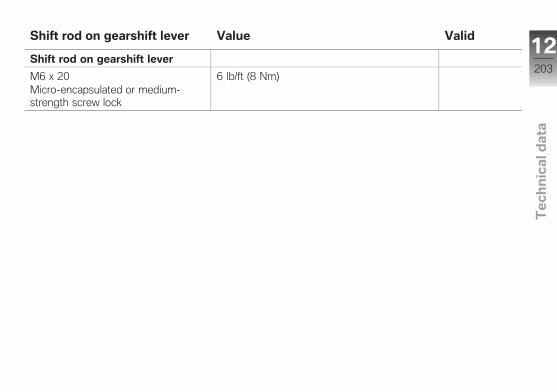
Shift rod on gearshift lever Value Valid
Shift rod on gearshift lever
M6 x 20Micro-encapsulated or medium-strength screw lock
6 lb/ft (8 Nm)
12203
z Te
ch
nic
al d
ata

Fuel
Recommended fuel quality Premium grade unleaded fuel (max. 10 %ethanol, E10)91 AKI (98 ROZ/RON)91 AKI
Alternative fuel quality Super unleaded (minor restrictions with regard topower and fuel consumption) (max. 10 % ethanol,E10)89 AKI (95 ROZ/RON)89 AKI
Usable fuel quantity Approx. 4.6 gal (Approx. 17.5 l)
Fuel reserve Approx. 1.1 gal (Approx. 4 l)
12204
z Te
ch
nic
al d
ata

Engine oil
Engine oil, capacity Approx. 3.7 quarts (Approx. 3.5 l), with filter re-placement
Viscosity rating
SAE 5W-40, API SL/JASO MA2 Additives (for instance, molybdenum-based substances) are prohibited, becausethey would attack the coatings on enginecomponents, BMW Motorrad recommendsBMW Motorrad ADVANTEC Ultimate Oil
Engine oil, quantity for topping up max 0.8 quarts (max 0.8 l), Difference betweenMIN and MAX
BMW recommends
12205
z Te
ch
nic
al d
ata

Engine
Engine design Water/oil-cooled 4-cylinder four-cycle in-line en-gine with four valves per cylinders and two over-head cams
Displacement 999 cc (999 cm3)
Cylinder bore 3.1 in (80 mm)
Piston stroke 2 in (49.7 mm)
Compression ratio 13:1
Rated output 199 hp (146 kW), at engine speed: 13500 min-1
with power reductionOE 107 hp (79 kW), at engine speed: 7750 min-1
Torque 83 lb/ft (113 Nm), at engine speed: 10500 min-1
with power reductionOE 72 lb/ft (97 Nm), at engine speed: 7750 min-1
Maximum engine speed max 14200 min-1
Idle speed 1250 min-1, Engine at operating temperature
12206
z Te
ch
nic
al d
ata

Clutch
Clutch design Multi-disk oil-bath clutch, slipper clutch
Transmission
Transmission design Claw-shifted 6-speed transmission integrated inengine housing
Transmission gear ratios 1.652 (76:46 teeth), Primary gear ratio2.647 (45:17 teeth), 1st gear2.091 (46:22 teeth), 2nd gear1.727 (38:22 teeth), 3rd gear1.500 (33:22 teeth), 4th gear1.360 (34:25 teeth), 5th gear1.261 (29:23 teeth), 6th gear
12207
z Te
ch
nic
al d
ata

Rear-wheel drive
Type of final drive Chain drive
Type of rear suspension Two-arm aluminum swinging arm
Number of teeth of rear-wheel drive (Pinion/sprocket)
17:45
Secondary gear ratio 2.647
Frame
Frame design Aluminum composite bridge frame, load-sharingengine
Location of type plate Frame at front right on steering head
Location of the vehicle identification number Frame at front right on steering head
12208
z Te
ch
nic
al d
ata

Suspension
Front wheel
Type of front suspension Upside-down telescopic forks
Spring travel, front 4.7 in (120 mm), on wheel
Rear wheel
Type of rear suspension Two-arm aluminum swinging arm
Type of final drive Chain drive
Spring travel, rear 4.7 in (120 mm), on wheel
Brakes
Type of front brake Hydraulic radially operated twin disc brake with 4-piston radial fixed caliper and floating brake discs
Brake-pad material, front Sintered metal
Type of rear brake Hydraulically operated disc brake with 1-pistonfloating caliper and fixed brake disc
Brake-pad material, rear Organic
12209
z Te
ch
nic
al d
ata

Wheels and tires
Recommended tire combinations An overview of the current tire approvals is avail-able from your authorized BMW Motorrad retaileror on the Internet at bmw-motorrad.com.
Speed category of front/rear tires W, minimum requirement: 168 mph (270 km/h)
Front wheel
Front wheel design Aluminum cast wheel
Front-wheel rim size 3.50" x 17"
Front tire designation 120/70 ZR 17
Load index for front tire At least 48
Permissible front-wheel imbalance max 0.2 oz (max 5 g)
Rear wheel
Rear wheel design Aluminum cast wheel
Rear-wheel rim size 6.0" x 17"
Rear tire designation 190/55 ZR 17
with forged wheelsOE 200/55 ZR 17
Load index for rear tire At least 63
Permissible rear-wheel imbalance max 1.6 oz (max 45 g)
12210
z Te
ch
nic
al d
ata

Tire inflation pressure
Tire pressure, front 36.3 psi (2.5 bar), with tire cold
Tire pressure, rear 42.1 psi (2.9 bar), with tire cold
Electrical system
Fuses
Fuse 1 10 A, Instrument cluster
Fuse 2 4 A, Cutoff relay, diagnosis plug, anti-theft alarmsystem
Fuse 3 Not in use
Fuse 4 7.5 A, Low-beam headlight
Fuse 5 7.5 A, High-beam headlight
Fuse 6 7.5 A, Optional accessory connector, license platelight
Fuse 7 4 A, Ignition switch/electronic immobilizer (EWS)
Fuse 8 4 A, Angular rate sensor, left multifunction switch,infrared receiver (optional accessories)
Main fuse 40 A
12211
z Te
ch
nic
al d
ata

Battery
Battery design AGM (Absorptive Glass Mat) battery.
Battery voltage 12 V
Battery capacity 8 Ah
with anti-theft alarm system (DWA) OE 10 Ah
Spark plugs
Spark plugs, manufacturer and designation NGK LMAR9D-J
Electrode gap of spark plug 0.03 in (0.8 mm)
Light sources
Bulb for high-beam headlight H7 / 12 V / 55 W
Bulbs for low-beam headlight H7 / 12 V / 55 W
Bulb for parking light W5W / 12 V / 5 W
Bulb for taillight/brake light LED
Bulbs for flashing turn indicators, front RY10W / 12 V / 10 W
Bulbs for flashing turn indicators, rear RY10W / 12 V / 10 W
Bulb for license-plate light W5W / 12 V / 5 W
12212
z Te
ch
nic
al d
ata

Dimensions
Motorcycle length 80.7 in (2050 mm), across splash guard
Motorcycle height 44.9 in (1140 mm), across windshield at DIN un-laden weight
Motorcycle width 32.5 in (826 mm), across mirrors
Rider's seat height 32.1 in (815 mm), without driver
Rider's inside-leg arc, heel to heel 71.1 in (1805 mm), without driver
Weights
Unladen weight 450 lbs (204 kg), DIN unladen weight, ready forroad, 90 % full tank of gas, without OE
Permissible gross weight 897 lbs (407 kg)
Maximum payload 448 lbs (203 kg)
12213
z Te
ch
nic
al d
ata

Performance data
Top speed min 124 mph (min 200 km/h)12214
z Te
ch
nic
al d
ata
Service
Reporting safety defects . . . . . . . . . . . 216
BMW Motorrad Service . . . . . . . . . . . . 217
BMW Motorrad MobilityServices . . . . . . . . . . . . . . . . . . . . . . . . . . . 217
Maintenance procedures . . . . . . . . . . 217
Maintenance schedule . . . . . . . . . . . . . 221
Standard BMW Service . . . . . . . . . . . . 222
Confirmation of maintenancework . . . . . . . . . . . . . . . . . . . . . . . . . . . . . . . 223
Confirmation of service . . . . . . . . . . . . 228
13215
z Se
rvic
e

Reporting safety defects
If you believe that your vehicle has a defect which could cause a crash or could causeinjury or death, you should immediately inform the National Highway Traffic Safety Ad-ministration (NHTSA) in addition to notifying BMW of North America, LLC.If NHTSA receives similar complaints, it may open an investigation, and if it finds that asafety defect exists in a group of vehicles, it may order a recall and remedy campaign.However, NHTSA cannot become involved in individual problems between you, yourretailer, or BMW of North America, LLC.To contact NHTSA, you may call the Vehicle Safety Hotline toll-free at 1-888-327-4236 (teletypewriter TTY for the deaf: 1-800-424-9153); go to the website http://www.safercar.gov; or write to: Administrator, NHTSA, 400 Seventh Street, SW.,Washington, DC 20590. You can also obtain other information about motor vehiclesafety from http://www.safercar.gov.
13216
z Se
rvic
e

BMW Motorrad ServiceWith its worldwide dealer net-work, BMW Motorrad can attendto you and your motorcycle inover 100 countries around theglobe. BMW Motorrad retailershave the technical informationand expertise needed to conductreliable service and repairs cover-ing every aspect of your BMW.You can find the nearest autho-rized BMW Motorrad retailerby visiting our Internet site at"www.bmw-motorrad.com".
WARNING
Improperly performed main-tenance and repair work.Accident hazard due to subse-quent damage.
BMW Motorrad recommendshaving corresponding work onyour motorcycle carried outby a specialized workshop,
preferably by an authorizedBMW Motorrad retailer.
To ensure that your BMW con-sistently remains in optimal con-dition BMW Motorrad urges youto observe the recommendedservice intervals.Have all maintenance and repairwork confirmed in the "Service"chapter in this manual. Doc-umentation confirming regularmaintenance is essential for gen-erous treatment of claims sub-mitted after the warranty periodhas expired (goodwill).
You can obtain information onthe contents of the BMW Ser-vices from your BMW Motorradretailer.
BMW Motorrad MobilityServicesThe BMW Motorrad Mobility Ser-vices furnish you and your newBMW motorcycle with extra se-curity by offering a wide array ofassistance services in the eventof a breakdown (BMW RoadsideAssistance, breakdown assis-tance, vehicle recovery and re-trieval, etc.).Contact your authorized BMWMotorrad retailer for additionalinformation on available mobility-maintenance services.
MaintenanceproceduresBMW Pre-Delivery CheckThe BMW pre-delivery check iscarried out by your authorizedBMW Motorrad retailer before itturns over the motorcycle to you.
13217
z Se
rvic
e

BMW Running-in Check
Carrying out the firstrunning-in check
300...750 miles(500...1200 km)
BMW ServiceBMW Service is carried out oncea year. The scope of the ser-vices performed may be depen-dent on the motorcycle ownerand the mileage driven. YourBMW Motorrad retailer confirmsthat the service has been per-formed and enters the date forthe next service.For riders who drive long dis-tances annually, it may be neces-sary to come in for service beforethe entered date. In this case acorresponding maximum odome-ter reading will also be entered inthe confirmation of service. If thisodometer reading is reached be-
fore the next service date, servicemust be performed sooner.
The service display in the multi-function display reminds you ofthe next service date approx. onemonth or 700 mls before the en-tered values.
The specified service intervalsapply to street operation. Forracing operation, adjust the inter-vals in accordance with loading.
More information on the topic ofservice is available at:bmw-motorrad.com/service
The required scope of mainte-nance work for your motorcy-cle can be found in the followingmaintenance plan:
13218
z Se
rvic
e

13219
z Se
rvic
e

13220
z Se
rvic
e

Maintenance schedule1 BMW running-in check2 Standard BMW Service
( 222)3 Engine oil change with fil-
ter4 Check valve clearance5 Checking the engine tim-
ing6 Replace all spark plugs7 Replacing air filter8 Telescopic fork oil change9 Change the brake fluid in
the entire systema annually or every
6000 miles (whichevercomes first)
b for the first time after oneyear, then every two years
13221
z Se
rvic
e

Standard BMW ServiceThe standard BMW Service in-cludes the following maintenancework:
Performing the brief test usingthe BMW Motorrad diagnosissystem.Visual inspection of brake lines,brake hoses and connections.Checking the front/rear brakefluid level.Checking the front/rear brakepads and brake discs for wear.Checking the steering headbearings.Checking the coolant level.Checking the fastening of theclutch lever assembly.Checking the clutch cable andclutch lever play.Lubricating the clutch control.Checking the drive chain, rearwheel sprocket and enginesprocket.
Checking the tyre pressure andtread depth.Checking the side stands forease of movement.Lubricating the side stand.Checking the lighting and sig-nal system.Checking that the engine start-ing suppression works.Final inspection and checkingfor road safety.Setting the service date andremaining distance to service.Checking the battery state ofcharge.Recording the BMW Service inthe on-board literature.
13222
z Se
rvic
e

Confirmation of maintenance work
BMW Pre-DeliveryCheckConducted
on
Stamp, Signature
BMW Running-inCheckConducted
on
Odometer reading
Next serviceat the latest
onor, if reached sooner,
Odometer reading
Stamp, Signature
13223
z Se
rvic
e

BMW ServiceConducted
on
Odometer reading
Next serviceat the latest
onor, if reached sooner,
Odometer reading
Stamp, Signature
BMW ServiceConducted
on
Odometer reading
Next serviceat the latest
onor, if reached sooner,
Odometer reading
Stamp, Signature
BMW ServiceConducted
on
Odometer reading
Next serviceat the latest
onor, if reached sooner,
Odometer reading
Stamp, Signature
13224
z Se
rvic
e

BMW ServiceConducted
on
Odometer reading
Next serviceat the latest
onor, if reached sooner,
Odometer reading
Stamp, Signature
BMW ServiceConducted
on
Odometer reading
Next serviceat the latest
onor, if reached sooner,
Odometer reading
Stamp, Signature
BMW ServiceConducted
on
Odometer reading
Next serviceat the latest
onor, if reached sooner,
Odometer reading
Stamp, Signature
13225
z Se
rvic
e

BMW ServiceConducted
on
Odometer reading
Next serviceat the latest
onor, if reached sooner,
Odometer reading
Stamp, Signature
BMW ServiceConducted
on
Odometer reading
Next serviceat the latest
onor, if reached sooner,
Odometer reading
Stamp, Signature
BMW ServiceConducted
on
Odometer reading
Next serviceat the latest
onor, if reached sooner,
Odometer reading
Stamp, Signature
13226
z Se
rvic
e

BMW ServiceConducted
on
Odometer reading
Next serviceat the latest
onor, if reached sooner,
Odometer reading
Stamp, Signature
BMW ServiceConducted
on
Odometer reading
Next serviceat the latest
onor, if reached sooner,
Odometer reading
Stamp, Signature
BMW ServiceConducted
on
Odometer reading
Next serviceat the latest
onor, if reached sooner,
Odometer reading
Stamp, Signature
13227
z Se
rvic
e

Confirmation of serviceThe table is intended as proof of maintenance and repair work, the installed optional accessories and anyspecial campaign (recall) work carried out.
Work carried out Odometerreading
Date
13228
z Se
rvic
e

Work carried out Odometerreading
Date 13229
z Se
rvic
e

13230
z Se
rvic
e

Appendix
Certificate for Electronic Immobi-lizer . . . . . . . . . . . . . . . . . . . . . . . . . . . . . . . . 232
14231
z Ap
pe
nd
ix

FCC Approval
Ring aerial in the ignition switch
To verify the authorization of the ignition key, the electronic immobilizer exchanges information with the ignition key via the ring aerial.
This device complies with Part 15 of the FCC rules. Operation is subject to the following two conditions:(1) This device may not
cause harmful inter-ference, and
(2) this device must accept any interference received, including interference that may cause undesired operation.
Any changes or modifi-cations not expressly
approved by the party responsible for compliance could void the user’s authority to operate the equipment.

Approbation de la FCC
Antenne annulaire présente dans le commutateur d'allumage
Pour vérifier l'autorisation de la clé de contact, le système d'immobilisation électronique échange des
informations avec la clé de contact via l'antenne annulaire.Le présent dispositif est conforme à la partie 15 des règles de la FCC. Son utilisation est soumise aux deux conditions suivantes :(1) Le dispositif ne
doit pas produire d'interférences nuisibles, et
(2) le dispositif doit pouvoir accepter toutes les interférences extérieures, y compris celles qui pourraient provoquer une activation inopportune.
Toute modification qui n'aurait pas été
approuvée expressément par l'organisme responsa-ble de l'homologation peut annuler l'autorisation accordée à l'utilisateur pour utiliser le dispositif.

AAbbreviations and symbols, 6ABS
Control, 16Operating, 50Self-diagnosis, 83Technology in detail, 142Warning light, 32
AccessoriesGeneral instructions, 194
Anti-theft alarm systemOperating, 48Warning light, 35
ASCOperating, 51Self-diagnosis, 84Switching off, 51Switching on, 52Technology in detail, 145Warning light, 33
Average valuesResetting, 47
BBattery
Charging, 187Connect to vehicle, 187Disconnect from vehicle, 186Installing, 188Maintenance instructions, 185Position on vehicle, 19Removing, 187Technical data, 212
Brake fluidChecking fluid level at rear, 164Checking front fluid level, 163Front reservoir, 15Rear reservoir, 15
Brake padsBreaking in, 86Check front, 161Checking rear, 162
BrakesAdjusting handlebar lever, 66Checking operation, 161Safety instructions, 88Technical Data, 209
Breaking in, 85
BulbsReplace taillight, 182Replacing front and rear turnindicator light sources, 180Replacing high-beam headlightlight source, 176Replacing light source for left-hand parking light, 178Replacing low-beam lightsource in headlight, 176Replacing right-hand parkinglight light source, 179Technical data, 212Warning light for light sourcedefect, 31
CChain
Adjusting tension, 190Check tension, 189Checking wear, 190Lubricating, 189
Checklist, 81Clock
Adjusting, 50
15234
z Ind
ex

ClutchAdjusting play, 166Check play, 166Checking operation, 165Technical Data, 207
Coding plugInstalling, 56
Confirmation of maintenancework, 223
CoolantChecking fill level, 166Fluid level indicator, 15Topping up, 167Warning light forovertemperature, 29
Cruise-control systemOperating, 57
DDamping
Adjust, without DDC, 72Adjusting, 72Adjusting, with DDC, 75Front adjustment element, 11Rear adjuster, 11, 15
DDCAdjusting, 75Technology in detail, 144
DimensionsTechnical Data, 213
DTCAdjusting control, 127Control, 16Indicator light, 33Operating, 52Self-diagnosis, 85Switching off, 53Switching on, 53Technology in detail, 145
DWAIndicator light, 20Warning light, 35
EElectrical system
Technical Data, 211Emergency on/off switch (kill
switch)Operating, 41Position on vehicle, 18
EngineEngine electronics warninglight, 29Parking, 41Starting, 82Technical Data, 206Warning light for enginemanagement system, 30
Engine oilCheck fill level, 159Fluid level indicator, 11, 13Oil fill location, 15Technical Data, 205Topping up, 160
Equipment, 7
FFairing
Installing fairing side panel, 184Remove fairing side panel, 183
Fall sensorIndicator light, 32
FrameTechnical Data, 208
15235
z Ind
ex

Front wheel standMounting, 157
FuelRefueling, 90Technical data, 204Technical Data, 204
Fuel reserveCruising range, 38Warning light, 37
FusesPosition on vehicle, 19Replacing, 188Technical data, 211
GGearshift assistant, 87, 152
HHazard warning flashers
Control, 16Operating, 43
HeadlightAdjusting for RHD/LHDtraffic, 66Headlight range, 66
Heated handlebar gripsControl, 18Operating, 60
Helmet holderPosition on vehicle, 19Securing helmet, 63
Horn, 16
IIgnition
Switching off, 41Switching on, 40
Immobilizer, 41Warning indicator, 29
Indicator lights, 20Overview, 22
Instrument clusterOverview, 20Photosensor, 20
JJump-start, 184
KKeys, 40
LLap-Timer
Clear recording, 108Deleting lap, 108Display structure, 121End time entry, 101Fastest lap expected, 102individualizing, 100Information on each racelap, 106Infrared receiver, 100Interrupting time entry, 101Operating, 98RACE INFO, 103Starting time recording, 100
Launch control, 128Start of race, 128
License-plate carrierRemoving/installing, 132
LightsControl, 16Low-beam headlight, 42Operating headlight flasher, 42Operating high-beamheadlight, 42
15236
z Ind
ex

Operating parking lights, 42Parking lights, 42
LuggageLoading information, 80
Luggage loopsPosition on vehicle, 19Using, 64
MMaintenance
General instructions, 156Maintenance schedule, 221
Maintenance intervals, 217Mirrors
Adjusting, 66Removing/installing, 131
Mobility Services, 217Motorcycle
Care, 195Cleaning, 195Parking, 89Returning to use, 198Storage, 198Tying down, 92
Multifunction display, 20Control, 16Display for racing mode, 96Exiting settings, 116LAPTIMER Operating, 98Overview, 23RACE INFO, 103Select submenu, 113Selecting display readings, 45Setting parameter, 115SETUP DDC-SYS, 117SETUP EQUIPMENT, 118SETUP MENU, 111SETUP RACETRACK, 120SETUP USER-MODE, 125
Multifunction switchGeneral view, left, 16General view, right, 18
NNotice concerning current
status, 7
OOnboard tool kit
Contents, 156Position on vehicle, 19
Overview of warningindicators, 25
OverviewsInstrument cluster, 20Left side of vehicle, 11, 13Left-side multifunctionswitch, 16Multifunction display, 23Right side of vehicle, 15Right-hand multifunctionswitch, 18SETUP DDC-SYS, 117SETUP EQUIPMENT, 118SETUP MENU, 111SETUP RACETRACK, 120SETUP USER-MODE, 125Underneath seat, 19Warning and indicator lights, 22
PParking light, 42Pre-Ride-Check, 83
15237
z Ind
ex

RRacetrack
Display for racing mode, 95LAPTIMER Operating, 98Race start with LaunchControl, 128Speed limiter for pit lane, 130
Rear-wheel driveTechnical Data, 208
Rear-wheel standMounting, 158
Refueling, 90Rider's Manual (US Model)
Position on vehicle, 19Riding mode
Adjusting, 53Control, 18Technology in detail, 146
SSafety instructions
On braking, 88On riding, 80
SeatsInstalling, 61Locking mechanism, 11, 13Removing, 61
Service, 217Reporting safety defects, 216
Service display, 37Shift lever
Shift pattern reversal, 136Shifting gears
Shiftpoint light, 20, 87Spark plugs, 212Speed limiter for pit lane
Adjust maximum speed, 125Operating, 130
Speed warningAdjusting, 59
Speedometer, 23Spring preload
Adjusting, 67Front adjustment element, 11,13Rear adjuster, 11, 13
Starting, 82Control, 18
Steering damperAdjusting, 67Position on vehicle, 15
Steering lockLocking, 40
SuspensionTechnical Data, 209
Switching off, 89
TTachometer, 20Technical data
Battery, 212Brakes, 209Clutch, 207Dimensions, 213Electrical system, 211Engine, 206Engine oil, 205Frame, 208Fuel, 204Fuses, 211Light sources, 212Rear-wheel drive, 208Spark plugs, 212
15238
z Ind
ex

Standards, 7Suspension, 209Transmission, 207Weights, 213Wheels and tires, 210
TiresBreaking in, 86Checking tire inflationpressures, 167Checking tire tread depth, 168Inflation pressure table, 11, 13Inflation pressures, 211Recommendation, 168Technical Data, 210
Torques, 201Traction Control
ASC, 145DTC, 145
TransmissionTechnical Data, 207
Trip distance recorderResetting, 47
Troubleshooting chart, 200
Turn indicatorsControl, 16Operating, 43Removing/installing, 134
Type platePosition on vehicle, 15
VVehicle identification number
Position on vehicle, 15
WWarning lamps, 20
ABS, 32Alarm system, 35ASC, 33Display, 24DTC, 33Electronic enginemanagement, 29Electronic immobilizer, 29Engine managementsystem, 30Fall sensor, 32Fuel reserve, 37Light source defect, 31
Overheating, 29Overview, 22Taillight and lights for parkinglights defective, 31
WeightsLoad capacity table, 11, 13Technical Data, 213
WheelsChecking wheel rims, 168Install rear wheel, 174Installing front wheel, 170Removing front wheel, 169Removing rear wheel, 172Size change, 169Technical Data, 210
15239
z Ind
ex

15240
z Ind
ex

The descriptions and illustrationsin this manual may vary fromyour own motorcycle's actualequipment, depending upon itsequipment level and accessoriesas well as your specific nationalversion. No claims stemmingfrom these differences can berecognized.Dimensions, weights, fuel con-sumption and performance dataare quoted to the customary tol-erances.The right to modify designs,equipment and accessories isreserved.Errors and omissions excepted.
© 2015 Bayerische MotorenWerke Aktiengesellschaft80788 Munich, GermanyReprints and duplication of thiswork, in whole or part, are pro-hibited without the express writ-ten approval of BMW Motorrad,Aftersales.
Original Rider's Manual, printed inGermany.

Important data for refueling:
Fuel
Recommended fuel quality Premium grade unleaded fuel (max. 10 % ethanol, E10)91 AKI (98 ROZ/RON)91 AKI
Alternative fuel quality Super unleaded (minor restrictions with regard to powerand fuel consumption) (max. 10 % ethanol, E10)89 AKI (95 ROZ/RON)89 AKI
Usable fuel quantity Approx. 4.6 gal (Approx. 17.5 l)
Fuel reserve Approx. 1.1 gal (Approx. 4 l)
Tire inflation pressure
Tire pressure, front 36.3 psi (2.5 bar), with tire cold
Tire pressure, rear 42.1 psi (2.9 bar), with tire cold
You'll find additional information on all aspects of your motorcycle at:bmwmotorrad.com
BMW recommends
Order No.: 01 41 8 565 38708.2015, 2nd edition, 07
*01418565387**01418565387**01418565387*