weld pool surface temperature measurement from
TRANSCRIPT
HAL Id: hal-01318648https://hal.archives-ouvertes.fr/hal-01318648
Submitted on 21 Dec 2017
HAL is a multi-disciplinary open accessarchive for the deposit and dissemination of sci-entific research documents, whether they are pub-lished or not. The documents may come fromteaching and research institutions in France orabroad, or from public or private research centers.
L’archive ouverte pluridisciplinaire HAL, estdestinée au dépôt et à la diffusion de documentsscientifiques de niveau recherche, publiés ou non,émanant des établissements d’enseignement et derecherche français ou étrangers, des laboratoirespublics ou privés.
Weld pool surface temperature measurement frompolarization state of thermal emission
Nicolas Coniglio, Alexandre Mathieu, Olivier Aubreton, Christophe Stolz
To cite this version:Nicolas Coniglio, Alexandre Mathieu, Olivier Aubreton, Christophe Stolz. Weld pool surface tempera-ture measurement from polarization state of thermal emission. Quantitative InfraRed ThermographyJournal, Taylor and Francis, 2016, 13 (1), pp.83-93. �10.1080/17686733.2015.1102475�. �hal-01318648�
Weld pool surface temperature measurement from polarization stateof thermal emission
Nicolas Coniglioa, Alexandre Mathieub*, Olivier Aubretonc and Christophe Stolzc
aLaboratoire MSMP, Arts et Metiers ParisTech, Aix en Provence, France; bLaboratoireInterdisciplinaire Carnot de Bourgogne (ICB), UMR 6303 CNRS-Université de Bourgogne
Franche-Comté, Dijon, France; cLaboratoire LE2I, UMR 6306 CNRS-Université de BourgogneFranche-Comté, Le Creusot, France
This paper presents a passive polarimetry method using a division of aperture opti-cal device in order to measure the temperature distribution at the weld pool surface.Thermal emission from a hot liquid metal was investigated at a near-infrared wave-length corresponding to a blind spectral window of a helium plasma generated dur-ing gas tungsten arc welding process. The refractive index of liquid metal and thesurface radiance are deduced from the polarisation state of thermal emissions. Basedupon the knowledge of both characteristics, the temperature distribution can becalculated.
Keywords: polarimetry; Stokes imaging; gas tungsten arc; weld pool temperature
1. Introduction
Vision-based methods are one of the non-contact solutions to provide insights on thestate of the weld pool surface hidden by the bright dazzling radiations of the weldingarc. The welding arc plasma emits radiations at specific spectral lines,[1] the wave-lengths of which are mainly determined by the shielding gas composition and theatoms evaporated from the weld pool during its interaction with the arc plasma.Observing the weld pool at a specific wavelength reduces the interference from the arcand facilitates the observation of the weld pool area behind the arc plasma.[2–4] Whilethermal emission intensity is related to the temperature of the emitting surface, theinter-dependence of the surface geometry and the observing setup is usually neglected.However, the emissivity of thermal radiation from an object depends upon both theangle of emission relative to the surface [5] and the surface temperature.[6]
Measurement of weld pool temperature is a real challenge for scientific research butalso for industrial applications. Non-contact methods are commonly preferred to contactmethods due to difficulties related to the environment: high temperature, molten metalspatters, intense radiation, dazzling effect, small scale and short time phenomena.Attempts to measure superficial temperature of the weld pool exist in literature review.Most of this works concerns feasibility studies of IR thermography sensing with the aimto control cooling rate near the weld pool,[7–14] for detecting contaminant/impurities onthe molten pool surface,[15] for penetration sensing,[16, 17] or for monitoring the size
*Corresponding author. Email: [email protected]

of the weld pool.[18] Few works concerns absolute temperature measurement on theweld pool surface. Among them, authors of [4] use IR thermography and assume adirect dependence between pixel grey levels and temperature. Authors of [19–23] usetwo-colour pyrometers to measure weld pool temperature, assuming an emissivity inde-pendent from wavelength. Others [24, 25] use optical emission spectroscopy to deter-mine a relation between emissivity and temperature. Then, they use this relation with IRimage to calculate a temperature map on weld pool surface. From our knowledge, theonly authors that do not neglect directionality of thermal emission coming from the weldpool surface are Kraus et al. [26, 27], who take into account for surface topology of theweld pool and optical axis angle of view. However, the Kraus method is difficult toachieve and is applicable only when the welding arc vanishes.
In the first part of this article, the principle of Stokes polarimetric analysis isreminded. Extension of this method to temperature measurement of weld pool surfaceis proposed assuming four initial postulates. The method used to determine the complexrefractive index is emphasised as it represents a key point of the proposed method. Inthe experimental part, description of the set-up is given. In the discussion part, themethod and the results are discussed. An interpretation of the observed scene isproposed.
2. Thermal radiation polarimetric analysis
From [28], body thermal emissions are linearly polarised parallel to the plane of inci-dence for objects presenting a particular aspect ratio, e.g. wire or fibre. In the presentwork, the local surface orientation is deduced from the polarimetric analysis of thenear-infrared radiations emitted by a weld pool composed of liquid steel. A complexrefractive index is estimated and, then, local temperature is calculated. Four initialpostulates are proposed to determine the temperature distribution:
• The weld pool edge is at the liquidus temperature, due to undercooling phe-nomenon, temperature variation of several degrees can be observed at the weldpool edge. In the works set out in this article, the weld pool is observed in sta-tionary condition, thus, reducing overcooling temperature variation at the weldpool edge.
• The emissivity of liquid iron at θ = 0° is assumed wavelength-independent in the650–810 nm range, which enables to use values at 650 nm [29]: ε (θ = 0°,λ = 810 nm) = ε (θ = 0°, λ = 650 nm) = 0.37.
• The weld pool radiance is related to the blackbody radiance at the same tempera-ture by the Planck law.
• The liquid metal emissivity is independent of its temperature for the temperaturerange investigated.
In opposite to some works in the close field,[30–32] thermal radiations are bodyemissions that can be partially linearly polarised in the far field,[33–37] but to a degreeof linear polarisation usually less than for surface reflection.[38] The degree of linearpolarisation depends upon the zenithal angle of the emitted radiation following achange in emissivity with the direction of radiation.[39] The polarisation of the infraredbody emission is modified with the surface roughness [40] or when surmounting thematerial with sub-wavelength periodic gratings.[41–45]

The polarisation direction changes to perpendicular to the plane of incidence forsmall object sizes, the critical size of which is of the same order of magnitude than thelight wavelength at which state the Fresnel terms derived under the assumption thatelectromagnetic radiation is reflected from a planar phase boundary of infinite extent.The degree of linear polarisation, called ρ, of thermal radiation is a monotonicallyincreasing function of the zenithal angle, called θ, leading to a non-ambiguous relation-ship, ρ(θ). This property was used to disambiguate the zenithal angle of the reflectedlight.[5] Thus, the polarised characteristics of the thermal signature contain geometricalinformation of the emitting surface.
The polarimetric analysis of the emitted radiations from the weld pool free surfaceis determined following the method described in [46]. Three (S0, S1, S2) out of the fourunknown Stokes parameters of the thermal radiations are determined by interpolatingthe equation for each corresponding pixel in each sub-image of a linear polariseroriented at an angle α:
I að Þ ¼ 1
2� S0 þ S1 � cos 2að Þ þ S2 � sin 2að Þð Þ (1)
I(α) is light magnitude at each pixel. The degree of linear polarisation ρ is defined as:
q ¼ffiffiffiffiffiffiffiffiffiffiffiffiffiffiffiS21 þ S22
pS0
(2)
The emissivity ε of thermal emissions is the mean value of the emissivities ɛ// and ɛ⊥of thermal emissions with a polarisation analysis direction parallel and perpendicular tothe plane of incidence, respectively. These emissivities are given by [47]:
e== ¼ 4n�cos hð Þn2þk2ð Þ�cos2 hð Þþ2n�cos hð Þþ1
e? ¼ 4n�cos hð Þcos2 hð Þþ2n�cos hð Þþn2þk2
((3)
where n and k are respectively real and imaginary parts of the complex refractive index.The emergence angle θ is then inferred using the bijective relationship:
q ¼ e== � e?e== þ e?
¼ n2 þ k2 � 1ð Þ � 1� cos2 hð Þð Þ1þ n2 þ k2ð Þ � 1þ cos2 hð Þð Þ þ 4n� cos hð Þ (4)
Once the emissivity of a radiated point has been calculated, its temperature T is calcu-lated based upon a calibrated relationship between the measured intensity S0 and theradiance of a blackbody at a known temperature. The relationship of the radiance ofthe weld pool surface L with the temperature T is given by Planck’s law:
T ¼ h� c
k� kB � ln 1þ 2 e�h�c2
k5�L
� � (5)
where λ is wavelength, h is Planck’s constant, kB is Boltzmann’s constant, and c isspeed of light. Hence the polarimetric state of radiated light permits both the thermalfield and topography reconstruction.
3. Determination of the complex refractive index
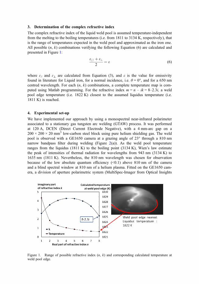
The complex refractive index of the liquid weld pool is assumed temperature-independentfrom the melting to the boiling temperatures (i.e. from 1811 to 3134 K, respectively), thatis the range of temperatures expected in the weld pool and approximated as the iron one.All possible (n, k) combinations verifying the following Equation (6) are calculated andpresented in Figure 1:
e== þ e?2
¼ e (6)
where ɛ// and ɛ⊥ are calculated from Equation (3), and ε is the value for emissivityfound in literature for Liquid iron, for a normal incidence, i.e. θ = 0°, and for a 650 nmcentred wavelength. For each (n, k) combinations, a complete temperature map is com-puted using Matlab programming. For the refractive index m = n – ik = 8–2.3i, a weldpool edge temperature (i.e. 1822 K) closest to the assumed liquidus temperature (i.e.1811 K) is reached.
4. Experimental set-up
We have implemented our approach by using a monospectral near-infrared polarimeterassociated to a stationary gas tungsten arc welding (GTAW) process. It was performedat 120 A, DCEN (Direct Current Electrode Negative), with a 4 mm-arc gap on a200 × 200 × 20 mm3 low-carbon steel block using pure helium shielding gas. The weldpool is observed with a GE1650 camera at a grazing angle of 23° through a 810 nmnarrow bandpass filter during welding (Figure 2(a)). As the weld pool temperatureranges from the liquidus (1811 K) to the boiling point (3134 K), Wien’s law estimatethe peak of intensities of thermal radiation for wavelengths from 943 nm (3134 K) to1635 nm (1811 K). Nevertheless, the 810 nm wavelength was chosen for observationbecause of the low absolute quantum efficiency (<0.1) above 810 nm of the cameraand a blind spectral window at 810 nm of a helium plasma. Fitted on the GE1650 cam-era, a division of aperture polarimetric system (MultiSpec-Imager from Optical Insights
Figure 1. Range of possible refractive index (n, k) and corresponding calculated temperature atweld pool edge.

Company based in Santa-Fe, New Mexico, USA) similar to one presented in [31]equips with four Polarcor linear polarisers 05P109AR.16 from Newport makes, simulta-neously, all polarisation measurements for every pixel of the dynamic scene(Figure 2(b)). The Multispec-Imager system captures different polarisation states of anobject at one single instant, thus suitable for observing dynamic scenes. The simultane-ous four-imaging system avoids the need of mechanically-rotating polarisation filtersahead of a CCD-sensor camera to acquire image components at different polarisationorientations. Hence there is no more time lag between rotation steps and no shift inperspective projection of the scene onto the image plane (optical distortion).[48] In thisconfiguration with linear polarising filters, the Multispec Imager is a partial Stokespolarimeter that evaluates the S0, S1 and S2 parameters. Low intensity current waspreferred to reduce background radiance of arc plasma.[1] Steel was chosen for itsrelatively high temperature of melting (1811 K) and consequently intense thermal radia-tions (Planck’s law). Lens diaphragm to f/2.8, corresponding to an approximate aperturediameter of 8.93 mm, and exposure time to 2400 μs are setup.
4.1. Temperature system calibration
Calibration of the system was required to analyse quantitatively the emission. The rela-tive grey-level attenuation coefficients of each light path (coefficients of 0.75, 1.00,1.33, and 0.86 for sub-image at 0, 35, 90, and 155 degrees, respectively) were evalu-ated by acquiring an image without polarised filters and applied on the correspondingpolarised sub-image. The object radiance L (W sr−1 m−2 nm−1), calculated withPlanck’s law, was associated to the Stokes parameter S0 by filming a heated blackbodymade in ceramic LaCrO3 from 473 to 1923 K inside a pyrometer calibration furnacePyrox PY15. The blackbody diameter is 15 mm. Images of the blackbody wereacquired using the camera equipped of the polarised filters and the 810 nm-bandpassfilter. The exposure time and diaphragm were adjusted in similarity to the adjustmentsduring welding observation. The parameter S0 is calculated for each acquired imageand associated to a temperature (Figure 3(a)). Considering an emissivity of 1 indepen-dent of the direction of thermal emission, the luminance of the body was estimated
Figure 2. (a) Division of aperture polarimetric system, and (b) raw focal-plane image(1200 × 1600 pixels) showing four polarisation channels at indicated orientation.

from its temperature using the Planck’s law. A mean value of S0 was calculated for a51x51 pixels region (Figure 3(b)). A linear best-fitting of the data points gives therelationship (7):
L ¼ 0:1298� S0 � 0:6619 (7)
The variation of S0 in this region was within 2% with a standard deviation below0.7%.
4.2. Polariser orientation calibration
The axis of the polarisation filters relative to each other were determined using a whitecomputer flat screen and pivoting the camera around its axis, which was perpendicularto the screen, see Figure 4. The white computer flat screen emits a linearly polarisedlight. Looking along the camera direction, the filters were oriented with respect to thefilter axis of the top-left image at 35° (bottom-left sub-image), 90° (bottom-right sub-image), and 155° (top-right image) in a trigonometric direction. The three parameters
Figure 3. (a) S0 (Stokes parameter) vs Temperature (K), (b) radiance (L) vs S0 calculated usingPlanck’s law, Equation (5).
Figure 4. (a) Experimental setup for calibration of filter orientation, and (b) intensity-orientationresults.

for partial linear polarisation can be derived from the four image radiances acquiredunder different polarising filter orientations. This calibration procedure of the entirevision system enables to account for polarisation anomalies induced by the optics.
5. Results and discussion
Infrared weld pool radiance is composed of external environment reflection, tungstentip glints, blackbody emission from wave facets (thermally emitted radiance). The dom-inant radiance intensity of the weld pool and tungsten tip allows us to neglect the envi-ronment contribution. The tungsten tip glint, located on a very small zone, contributesby reflection to the polarised information but will be treated as a strong emitted lightpoint to simplify this approach. The emission from the weld pool facets is the signalwe are interested in. The emitted radiations may be affected by the transmitting med-ium (i.e. atmosphere) before reaching the camera sensor. The transmission through thesurrounding atmosphere and emission from the helium plasma is neglected as this onedoes not emit significantly in the selected spectral wavelength.
Multiple reflections, in which the light reaches the detector after two or more reflec-tions from the weld pool surface, and shadowing, in which one facet blocks the viewof the facet behind it, are not accounted for. These effects become important for largecapillary waves travelling along the phase boundary of the liquid metal, whose dynam-ics are dominated by the effects of surface tension often referred to as ripples, and forgrazing camera viewpoints. GTA weld pool is performed without electrode displace-ment and with welding parameters generating a ‘calm’ surface, in particular by using aconstant welding current to minimise superficial oscillations. If selecting a too-grazingpath, multiple scattering and shadowing are expected to dominate single-scatteringevents. Hence the camera viewpoint is selected as much vertical as possible so that thetungsten tip does not physically hide parts of the weld pool.
In Figure 5, calculated images for S0, S1 and S2 parameters are shown. The weldpool and the tungsten tip edges are easily identified. Some ghost-effect at the tungstentip is believed to arise from internal reflection of the light and the intense emission ofthe tungsten tip at these camera adjustments. The saturation of the tungsten tip is a con-sequence of these camera adjustments. The weld pool emits thermal radiations withlower intensity than tungsten tip because, at high temperatures, the tip emits more lightand peak is closer to 810 nm according to Wien’s law. It is proven by the presentimages that the weld pool and tungsten tip are glowing objects emitting energy in the
Figure 5. S0, S1 and S2 parameters are calculated. Background values are not relevant.

810 nm wavelength during GTAW process. ρ, i.e. degree of linear polarisation iscalculated from the S0, S1 and S2 Stokes parameters. Then, θ, i.e. zenithal angle, isdetermined using Equation (4).
The brightest zone in Figure 6(a), at a temperature estimated above 2367 K in (b),is due to oxide aggregate floating at weld pool surface. The hot spot stays at the weldpool centre for convex welds but wanders along the weld pool edge for concave welds.Oxide aggregate is formed, progressively, during welding performance by accumulationof smaller oxide particles. Most of them formed at the solid edge of the weld pool thatis at high temperature and are brought into the weld pool by the expansion (i.e. increas-ing diameter) of it. The heating spot is observed to stick to the oxide island preferen-tially. The oxides move under the complex action of the Marangoni flow, shielding gasflow, and arc pressure. The bright lines emerging from this hot spot (Figure 6(a)) arevisible in the reconstructed thermal field (Figure 6(b)) and may be hot liquid flowingaway from this zone due to Marangoni convection phenomenon.
6. Conclusion
In opposite to the work of Kraus et al., our method does not require assumptions withrespect to the dependence of emissivity on direction. Compared to polychromatic orbichromatic measurement methods, our method does not need to assume that emissivityis independent from wavelength within the two or more used spectral bands. Themethod is usable during welding process, and is fast enough to be sensitive to weldpool dynamic behaviour.
The polarimetry of thermal radiations permits a dense reconstruction of the thermalfield occurring on weld pool surfaces. Nevertheless, sources of errors must be identifiedprior to technological developments. Among those likely error sources are the back-ground emission of arc plasma (see our recent work in [48]), the floating oxides emit-ting at different emissivities and temperatures and the lack of knowledge concerningoptical properties of metallic liquid surface. Also, the lack of knowledge about under-cooling temperature of metal induces a source of error for a precise determination of
Figure 6. (a) Convex weld pool, and (b) calculated thermal field at the surface.

complex refractive index. The postulate that liquid iron normal emissivity is wavelengthindependent in the range 650–810 nm can be a source of error, better estimation of theemissivity is necessary.
A more universal observation window must be found in the infrared region. Thetechnological innovations should be extendable to other welding processes, i.e. MIG,Plasma, Laser and even other applications. The thermal field visualisation will informon the surface Marangoni flows. The shape and thermal field of MIG droplets could bedetermined. An innovative process may follow to control assembling processes and toperform non-contact dimensional control. It may be included to quality control ofindustrial systems.
AcknowledgementThe authors acknowledge the Conseil Régional de Bourgogne for the financial support of thiswork.
Disclosure statementNo potential conflict of interest was reported by the authors.
References[1] Weglowski MS. Investigation on the arc light spectrum in GTA welding. JAMME.
2007;20:519–522.[2] Abdullah BM. Monitoring of welding using Laser diodes. In: Dnyaneshwar SP, editor. Semi-
conductor Laser diode technology and applications. Rijeka: InTech; 2012. p. 241–262.Available from: http://www.intechopen.com/books/semiconductor-laser-diode-technology-and-applications/monitoring-of-welding-using-laser-diodes.
[3] Huang RS, Liu LM, Song G. Infrared temperature measurement and interference analysis ofmagnesium alloys in hybrid laser-TIG welding process. Mater. Sci. Eng. A. 2007;447:239–243.
[4] Zhang G, Wu CS, Liu Z. Experimental observation of both keyhole and its surrounding ther-mal field in plasma arc welding. Int. J. Heat Mass Transfer. 2014;70:439–448.
[5] Miyazaki D, Saito M, Sato Y, et al. Determining surface orientations of transparent objectsbased on polarization degrees in visible and infrared wavelength. J. Opt. Soc. Am. A.2002;19:687–694.
[6] Bimonte G, Cappellin L, Carugno G, et al. Polarized thermal emission by thin metal wires.New J. Phys. 2009;11. Article ID: 033014 (p. 11).
[7] Lukens W, Morris R, Dunn E. IR temperature sensing of cooling rates for arc welding con-trol. DTNSRDC/SME-80/70. Bethesda (MD); 1981; p. 20084.
[8] Doong JL, Wu CS, Hwang JR. Infrared temperature sensing of laser welding. Int. J. Mach.Tools Manuf. 1991;31:607–616.
[9] Moreira P, Frazão O, Tavares S, et al. Temperature field acquisition during gas metal arcwelding using thermocouples, thermography and fibre Bragg grating sensors. Meas. Sci.Technol. 2007;18:877–883.
[10] Liang G, Yuan S. Study on the temperature measurement of AZ31B magnesium alloy ingas tungsten arc welding. Mater. Lett. 2008;62:2282–2284.
[11] Liu L, Chi M, Huang R, et al. Infrared measurement and simulation of magnesium alloywelding temperature field. Sci. China Ser. E. 2005;48:706–715.
[12] Boillot J, Cielo P, Begin G, et al. Adaptive welding by fiber optic thermographic sensing:an analysis of thermal and instrumental considerations. Weld. J.: Weld. Res. Suppl.1985:209s–218s.
[13] Matteï S, Grevey D, Mathieu A, et al. Using infrared thermography in order to comparelaser and hybrid (laser+MIG) welding processes. Opt. Las. Technol. 2009;41:665–670.

[14] Mathieu A, Matteï S, Deschamps A, et al. Temperature control in laser brazing of a steel/aluminium assembly using thermographic measurements. NDT and E Int. 2006;39:272–276.
[15] Chin D, Madsen N, Goodling J. Infrared thermography for sensing the arc welding process.Weld. J.: Weld. Res. Suppl. 1983:227s–234s.
[16] Nagajaran S, Chen W, Chin B. Infrared sensing for adaptive arc welding. Weld. J.: Weld.Res. Suppl. 1989:462s–466s.
[17] Chen W, Chin B. Monitoring joint penetration using infrared sensing techniques. Weld. J.:Weld. Res. Suppl. 1990:181s–185s.
[18] Bicknell A, Smith J, Lucas J. Infrared sensor for top face monitoring of weld pools. Meas.Sci. Technol. 1994;5:371–378.
[19] Bertrand P, Smurov I, Grevey D. Application of near infrared pyrometry for continuous Nd:YAG laser welding of stainless steel. Appl. Surf. Sci. 2000;168:182–185.
[20] Doubenskaia M, Bertrand P, Smurov I. Pyrometry in laser surface treatment. Surf. Coat.Technol. 2009;201:1955–1961.
[21] Bertrand P, Ignatiev M, Flamant G, et al. Pyrometry applications in thermal plasma process-ing. Vacuum. 2000;56:71–76.
[22] Tanaka M, Waki K, Tashiro S, et al. Visualizations of 2D temperature distribution of moltenmetal in arc welding process. T. JWRI. 2009;38:1–4.
[23] Siewert E, Schein J, Forster G. Determination of enthalpy, temperature, surface tension andgeometry of the material transfer in PGMAW for the system argon–iron. J. Phys. D Appl.Phys. 2013;46:224008.
[24] Shöpp H, Sperl A, Kozakov R, et al. Temperature and emissivity determination of liquidsteel S235. J. Phys. D: Appl. Phys. 2012;45:235203.
[25] Kozakov R, Schöpp H, Gött G, et al. Weld pool temperatures of steel S235 while applyinga controlled short-circuit gas metal arc welding process and various shielding gases. J. Phys.D: Appl. Phys. 2013;46:475501.
[26] Kraus H. Optical spectral radiometric method for measurement of weld pool surface temper-atures. Opt. Lett. 1986;11:773–775.
[27] Kraus H. Experimental measurement of stationary SS 304, SS 316L and 8630 GTA weldpool surface temperatures. Weld. J.: Weld. Res. Suppl. 1989:269s–279s.
[28] Klein L, Ingvarsson S, Hamann H. Changing the emission of polarized thermal radiationfrom metallic nanoheaters. Opt. Express. 2009;17:17963–17969.
[29] Weast RC. CRC handbook of chemistry and physics. 69th ed; Boca Raton (FL): CRC PressInc; 1988. E-405.
[30] Coniglio N, Mathieu A, Aubreton O, et al. Characterizing weld pool surfaces from polariza-tion state of thermal emissions. Opt. Lett. 2013;38:2086–2088.
[31] Tyo JS, Goldstein D, Chenault D, et al. Review of passive imaging polarimetry for remotesensing applications. Appl. Opt. 2006;45:5453–5469.
[32] Klein L, Hamann H, Au Y, et al. Coherence properties of infrared thermal emission fromheated metallic nanowires. Appl. Phys. Lett. 2008;92:213102–213106.
[33] Yannopapas V. Effect of material spatial dispersion in the degree of polarization of thermalradiation emitted by a spherical source. Opt. Commun. 2010;283:4494–4498.
[34] Ingvarsson S, Klein L, Au Y, et al. Enhanced thermal emission from individual antenna-likenanoheaters. Opt. Express. 2007;15:11249–11254.
[35] Hesketh P, Zemel J, Gebhart B. Polarized spectral emittance from periodic micromachinedsurfaces. I. Doped silicon: the normal direction. Phys. Rev. B. 1988;37:10795–10802.
[36] Hesketh P, Zemel J, Gebhart B. Polarized spectral emittance from periodic micromachinedsurfaces. II. Doped silicon: angular variation. Phys. Rev. B. 1988;37:10803–10813.
[37] Marquier F, Joulain K, Mulet J, et al. Coherent spontaneous emission of light by thermalsources. Phys. Rev. B. 2004;69:155412.
[38] Bertilone D. Stokes parameters and partial polarization of far-field radiation emitted by hotbodies. J. Opt. Soc. Am. A. 1994;11:2298–2304.
[39] Rahmann S, Canterakis N. Reconstruction of specular surfaces using polarization imaging.IEEE. Proceedings of the conference on Computer Vision and Pattern Recognition; KauaiMarriott (HI): IEEE Computer Society; 2001.
[40] Worthing A. Deviation from Lambert’s law and polarization of light emitted by incandescenttungsten, tantalum and molybdenum and changes in the optical constants of tungsten withtemperature. J. Opt. Soc. Am. A. 1926;13:635–647.

[41] Jordan D, Lewis G. Measurements of the effect of surface roughness on the polarizationstate of thermally emitted radiation. Opt. Lett. 1994;19:692–694.
[42] Lee JH, Lee JCW, Leung W, et al. Polarization engineering of thermal radiation usingmetallic photonic crystals. Adv. Mater. 2008;20:3244–3247.
[43] Lee JH, Leung W, Kim T, et al. Polarized thermal radiation by layer-by-layer metallic emit-ters with sub-wavelength grating. Opt. Express. 2008;16:8742–8747.
[44] Dahan N, Niv A, Biener G, et al. Thermal image encryption obtained with a SiO2 space-variant subwavelength grating supporting surface phonon-polaritons. Opt. Lett.2005;30:3195–3197.
[45] Dahan N, Niv A, Biener G, et al. Space-variant polarization manipulation of a thermal emis-sion by a SiO2 subwavelength grating supporting surface phonon-polaritons. Appl. Phys.Lett. 2005;86:191102.
[46] Wilkie A, Weidlich A. A physically plausible model for light emission from glowing solidobjects. Comput. Graph. Forum. 2011;30:1269–1276.
[47] Gurton KP, Dahmani R, Videen G. Measured degree of infrared polarization for a variety ofthermal emitting surfaces. U.S. Army Research Lab. ARL-TR-3240. Adelphi (MD); 2004.
[48] Coniglio N, Mathieu A, Aubreton O, et al. Plasma effect on weld pool surface reconstruc-tion by shape-from-polarization analysis. Appl. Phys. Lett. 2014;104:131603.