what bsa configuration is best for lte-advanced? · what base station antenna configuration is best...
TRANSCRIPT
What base station antenna configuration is best for LTE-Advanced?
Kevin Linehan Vice president & chief technology officer,Antenna Systems, CommScope
Julius RobsonIndependent wireless technology consultant
White paper
commscope.com 2
Contents
Abstract 3
Introduction 3
Antennacharacteristics 4
Cross-polarantennasandportcorrelation 4
Anglecpread 4
Antennaarrayspacingandportcorrelation 4
Correlationforverticalversushorizontalantennas 5
Verticalconfigurationbeamformsinelevation,horizontalinazimuth 5
Summaryofantennacharacteristics 5
LTEMIMOmodes 6
ModeadaptationinLTE-Advanced 6
Single-user MIMO 7
Multi-userMIMO 7
Transmitbeamforming 8
WhyMU-MIMOandbeamformingprefercorrelatedantennas 9
ComparisonofMIMOmodesandpreferredantennacharacteristics 9
Conclusion 10
Summary 11
Bibliography 11
About the authors 12
commscope.com 3
Introduction
The rapidly increasing demand for mobile broadband traffic drives the need for even more capacity from cellular networks. This can be achieved by a combination of more spectrum, more cell sites and increased spectral efficiency for each site. In this paper, we focus on the latter, in particular the benefits achieved through MIMO technologies implemented in LTE and LTE-Advanced networks.
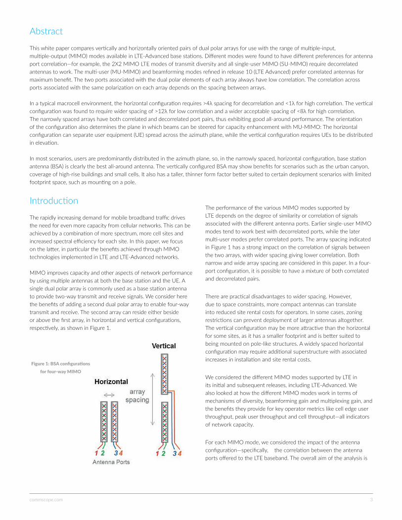
MIMO improves capacity and other aspects of network performance by using multiple antennas at both the base station and the UE. A single dual polar array is commonly used as a base station antenna to provide two-way transmit and receive signals. We consider here the benefits of adding a second dual polar array to enable four-way transmit and receive. The second array can reside either beside or above the first array, in horizontal and vertical configurations, respectively, as shown in Figure 1.
The performance of the various MIMO modes supported by LTE depends on the degree of similarity or correlation of signals associated with the different antenna ports. Earlier single-user MIMO modes tend to work best with decorrelated ports, while the later multi-user modes prefer correlated ports. The array spacing indicated in Figure 1 has a strong impact on the correlation of signals between the two arrays, with wider spacing giving lower correlation. Both narrow and wide array spacing are considered in this paper. In a four-port configuration, it is possible to have a mixture of both correlated and decorrelated pairs.
There are practical disadvantages to wider spacing. However, due to space constraints, more compact antennas can translate into reduced site rental costs for operators. In some cases, zoning restrictions can prevent deployment of larger antennas altogether. The vertical configuration may be more attractive than the horizontal for some sites, as it has a smaller footprint and is better suited to being mounted on pole-like structures. A widely spaced horizontal configuration may require additional superstructure with associated increases in installation and site rental costs.
We considered the different MIMO modes supported by LTE in its initial and subsequent releases, including LTE-Advanced. We also looked at how the different MIMO modes work in terms of mechanisms of diversity, beamforming gain and multiplexing gain, and the benefits they provide for key operator metrics like cell edge user throughput, peak user throughput and cell throughput—all indicators of network capacity.
For each MIMO mode, we considered the impact of the antenna configuration—specifically, the correlation between the antenna ports offered to the LTE baseband. The overall aim of the analysis is
Abstract This white paper compares vertically and horizontally oriented pairs of dual polar arrays for use with the range of multiple-input, multiple-output (MIMO) modes available in LTE-Advanced base stations. Different modes were found to have different preferences for antenna port correlation—for example, the 2X2 MIMO LTE modes of transmit diversity and all single-user MIMO (SU-MIMO) require decorrelated antennas to work. The multi-user (MU-MIMO) and beamforming modes refined in release 10 (LTE Advanced) prefer correlated antennas for maximum benefit. The two ports associated with the dual polar elements of each array always have low correlation. The correlation across ports associated with the same polarization on each array depends on the spacing between arrays.
In a typical macrocell environment, the horizontal configuration requires >4λ spacing for decorrelation and <1λ for high correlation. The vertical configuration was found to require wider spacing of >12λ for low correlation and a wider acceptable spacing of <8λ for high correlation. The narrowly spaced arrays have both correlated and decorrelated port pairs, thus exhibiting good all-around performance. The orientation of the configuration also determines the plane in which beams can be steered for capacity enhancement with MU-MIMO: The horizontal configuration can separate user equipment (UE) spread across the azimuth plane, while the vertical configuration requires UEs to be distributed in elevation.
In most scenarios, users are predominantly distributed in the azimuth plane, so, in the narrowly spaced, horizontal configuration, base station antenna (BSA) is clearly the best all-around antenna. The vertically configured BSA may show benefits for scenarios such as the urban canyon, coverage of high-rise buildings and small cells. It also has a taller, thinner form factor better suited to certain deployment scenarios with limited footprint space, such as mounting on a pole.
Figure1:BSAconfigurationsforfour-wayMIMO
commscope.com 4
to understand how well different antenna configurations will work with different MIMO modes, and the resulting performance benefits of each.
Antenna characteristics
Cross-polar antennas and port correlation
Correlation between antenna ports impacts MIMO performance. Referring back to Figure 1, each array has two ports for the two orthogonal slant polarizations of ±45 (ports 1/2 and 3/4). Low mutual correlation requires a good degree of cross-polar discrimination in the antenna design1, as well as low levels of polarization mixing in the propagation environment. The experience of operators demonstrates that good decorrelated performance from such antennas is achievable in practice2.
Angle spread
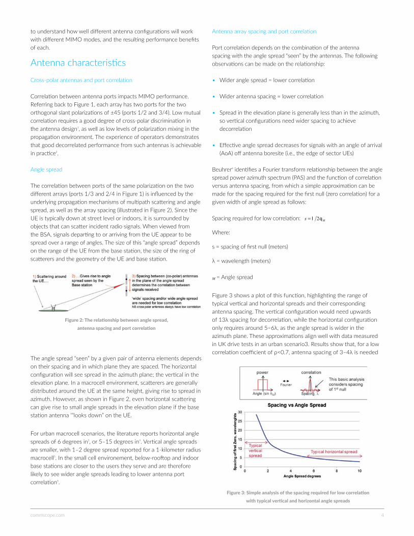
The correlation between ports of the same polarization on the two different arrays (ports 1/3 and 2/4 in Figure 1) is influenced by the underlying propagation mechanisms of multipath scattering and angle spread, as well as the array spacing (illustrated in Figure 2). Since the UE is typically down at street level or indoors, it is surrounded by objects that can scatter incident radio signals. When viewed from the BSA, signals departing to or arriving from the UE appear to be spread over a range of angles. The size of this “angle spread” depends on the range of the UE from the base station, the size of the ring of scatterers and the geometry of the UE and base station.
The angle spread “seen” by a given pair of antenna elements depends on their spacing and in which plane they are spaced. The horizontal configuration will see spread in the azimuth plane; the vertical in the elevation plane. In a macrocell environment, scatterers are generally distributed around the UE at the same height, giving rise to spread in azimuth. However, as shown in Figure 2, even horizontal scattering can give rise to small angle spreads in the elevation plane if the base station antenna ‘“looks down” on the UE.
For urban macrocell scenarios, the literature reports horizontal angle spreads of 6 degrees in3, or 5–15 degrees in4. Vertical angle spreads are smaller, with 1–2 degree spread reported for a 1-kilometer radius macrocell5. In the small cell environement, below-rooftop and indoor base stations are closer to the users they serve and are therefore likely to see wider angle spreads leading to lower antenna port correlation5.
Antenna array spacing and port correlation
Port correlation depends on the combination of the antenna spacing with the angle spread “seen” by the antennas. The following observations can be made on the relationship:
• Wider angle spread = lower correlation
• Wider antenna spacing = lower correlation
• Spread in the elevation plane is generally less than in the azimuth, so vertical configurations need wider spacing to achieve decorrelation
• Effective angle spread decreases for signals with an angle of arrival (AoA) off antenna boresite (i.e., the edge of sector UEs)
Beuhrer6 identifies a Fourier transform relationship between the angle spread power azimuth spectrum (PAS) and the function of correlation versus antenna spacing, from which a simple approximation can be made for the spacing required for the first null (zero correlation) for a given width of angle spread as follows:
Spacing required for low correlation: Ms ql 2=
Where:
s = spacing of first null (meters)
λ = wavelength (meters)
M = Angle spread
Figure 3 shows a plot of this function, highlighting the range of typical vertical and horizontal spreads and their corresponding antenna spacing. The vertical configuration would need upwards of 13λ spacing for decorrelation, while the horizontal configuration only requires around 5–6λ, as the angle spread is wider in the azimuth plane. These approximations align well with data measured in UK drive tests in an urban scenario3. Results show that, for a low correlation coefficient of ρ<0.7, antenna spacing of 3–4λ is needed
Figure2:Therelationshipbetweenanglespread, antennaspacingandportcorrelation
Figure3:Simpleanalysisofthespacingrequiredforlowcorrelation withtypicalverticalandhorizontalanglespreads
commscope.com 5
for a horizontal configuration and 12–13λ for a vertical configuration. For a high correlation of ρ>0.8, the vertical configuration required <8λ spacing. In a 3GPP contribution, operators provide the general guideline for the horizontal configuration2: closely spaced (i.e., high correlation) is achieved with a spacing of 0.5–0.7λ, and widely spaced is achieved with a spacing of 4–10λ.
Correlation for vertical versus horizontal antennas
As shown in the previous section, the vertical configuration typically needs to be more widely spaced than the horizontal to achieve decorrelation in a typical macrocell scenario. However, since array antennas themselves are generally taller than their width (for accurate elevation pattern shaping), then wider vertical spacing would be generally the case, as seen in Figure 1.
In a paper published in 1980, Adachi provided strong recommendations for vertically spaced antenna configurations over the horizontal3. He claimed that the 12–13λ separation needed was easily achieved and that, unlike the horizontal configuration, the low correlation properties were not sensitive to the AoA of the UE’s signal. In the omnidirectional cells of the time, some UEs may sit along the end-fire direction of a horizontal configuration, and thus the effective antenna spacing would be zero. History has shown, however, that the end-fire AoA issue was mitigated instead by the move from omnidirectional to tri-sectored base stations, where worst-case AoA is reduced to 30–60 degree off boresite. Horizontally separated antennas have proven to be the popular choice for diversity at macrocell sites. Nonetheless, this issue may be raised again as operators move towards small cell networks that are likely to be omnidirectional8. With the severe space constraints of small cell sites, a vertical configuration may again be appealing.
More recent measurement campaigns also show that a vertical configuration has benefits over horizontal in the modern multi-antenna cellular network. One drive test campaign9 showed that a vertical array configuration with 10λ spacing achieved higher throughputs at the higher signals to interference and noise ratios, or SINRs, compared to horizontal configuration with 1.5λ spacing. Benefits were attributed to the increased use of rank two MIMO transmission for higher SINR (near-in) UEs. Similar results were found in other recent drive tests10. These results suggest the closely spaced vertical configuration may result in lower port correlations than the horizontal.
Another interesting property of the vertical configuration is that correlation of the ports at the base station changes with the range of the UE. Kitao11 shows, by mathematical analysis, that, for a given angle spread, near-in UEs produce higher correlation across the base station antenna ports and cell-edge UEs have lower correlation. This characteristic could enable better diversity for cell-edge UEs without sacrificing beamforming and MU MIMO performance for near-in UEs.
Vertical configuration beamforms in elevation, horizontal in azimuth
Classical beamforming typically uses an array of closely spaced antenna elements to form a directive beam, where the relative phase of the signal to each element can be adjusted to steer the beam’s angle. The same principle can be applied to form beams with our two-antenna arrays. An important limitation is that the beam can only be formed in the same plane as the antenna elements, over which the phase slope can be adjusted1. It follows that the horizontal configuration can steer beams in the azimuth plane and the vertical configuration in elevation. An illustration of this concept can be seen in Figure 8 in the Multi-user MIMO section.
Summary of antenna characteristics
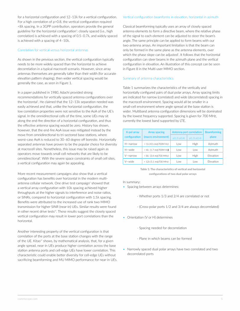
Table 1 summarizes the characteristics of the vertically and horizontally configured pairs of dual polar arrays. Array spacing limits are indicated for narrow (correlated) and wide (decorrelated) spacing in the macrocell environment. Spacing would all be smaller in a small-cell environment where angle spread at the base station is wider. Multiband antenna configuration dimensions will be dominated by the lowest frequency supported. Spacing is given for 700 MHz, currently the lowest band supported by LTE.
X-pol array
configuration
Array spacing
(macro environment)
Antenna port correlation Beamforming
planep(1,2) p(3,4) p(1,3) p(2,4)
H—narrow < 1λ (43 cm@700M Hz) Low High Azimuth
H—wide > 4λ (1.7 m@700M Hz) Low Low Azimuth
V—narrow < 8λ (3.4 m@700 MHz) Low High Elevation
V—wide > 12λ (5.1 m@700 MHz) Low Low Elevation
In summary: • Spacing between arrays determines: - Whether ports 1/3 and 2/4 are correlated or not
- (Cross-polar ports 1/2 and 3/4 are always decorrelated)
• Orientation (V or H) determines
- Spacing needed for decorrelation
- Plane in which beams can be formed
• Narrowly spaced dual polar arrays have two correlated and two decorrelated ports
Table1:Thecharacteristicsofverticalandhorizontal configurationsoftwodualpolararrays
commscope.com 6
LTE MIMO modes
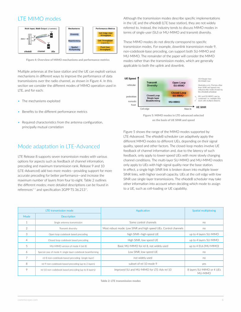
Multiple antennas at the base station and the UE can exploit various mechanisms in different ways to improve the performance of data transmissions over the radio channel, as shown in Figure 4. In this section we consider the different modes of MIMO operation used in LTE, and for each:
• The mechanisms exploited
• Benefits to the different performance metrics
• Required characteristics from the antenna configuration, principally mutual correlation
Mode adaptation in LTE-Advanced
LTE Release 8 supports seven transmission modes with various options for aspects such as feedback of channel information, precoding and maximum transmission rank. Release 9 and 10 (LTE-Advanced) add two more modes—providing support for more accurate precoding for better performance—and increase the maximum number of layers from four to eight. Table 2 outlines the different modes; more detailed descriptions can be found in references12, 5 and specification 3GPP TS 36.21313.
LTE transmission mode Application Spatial multiplexing
Mode Description
1 Single antenna transmission Some control channels no
2 Transmit diversity Most robust mode: Low SINR and high speed UEs. Control channels no
3 Open loop codebook based precoding high SINR—high-speed UE up to 4 layers SU-MIMO
4 Closed loop codebook based precoding High SINR, low-speed UE up to 4 layers SU-MIMO
5 MU-MIMO version of mode 4 (rel 8) Basic MU-MIMO for rel 8, not widely used up to 4 EUs (MU-MIMO)
6 Special case of mode 4: single layer codebook beamforming Low SINR, low-speed UE no
7 rel 8 non-codebook-based precoding (single layer) not widely used no
8 rel 9 non-codebook-based precoding (up to 2 layers) subset of rel 10 mode 9 yes
9 rel 10 non-codebook based precoding (up to 8 layers)) Improved SU and MU-MIMO for LTE-Adv rel 10 8 layers SU-MIMO or 4 UEs MU-MIMO
Although the transmission modes describe specific implementations in the UE and the eNodeB (LTE base station), they are not widely referred to. Instead, the industry tends to discuss MIMO modes in terms of single-user (SU) or MU-MIMO and transmit diversity.
These MIMO modes do not directly correspond to specific transmission modes. For example, downlink transmission mode 9, non-codebook-base precoding, can support both SU-MIMO and MU-MIMO. The remainder of the paper will consider the MIMO modes rather than the transmission modes, which are generally applicable to both the uplink and downlink.
Figure 5 shows the range of the MIMO modes supported by LTE-Advanced. The eNodeB scheduler can adaptively apply the different MIMO modes to different UEs, depending on their signal quality, speed and other factors. The closed-loop modes involve UE feedback of channel information and, due to the latency of such feedback, only apply to lower-speed UEs with more slowly changing channel conditions. The multi-layer SU-MIMO and MU-MIMO modes only apply to UEs with high signal quality near the base station. In effect, a single high SINR link is broken down into multiple lower SINR links, with higher overall capacity. UEs at the cell edge with low SINR use single-layer transmissions. The eNodeB scheduler may take other information into account when deciding which mode to assign to a UE, such as cell-loading or UE capability.
Figure4:OverviewofMIMOmechanismsandperformancemetrics
Table2:LTEtransmissionmodes
Figure5:MIMOmodesinLTE-advancedselected onthebasisofUESINRandspeed
commscope.com 7
A data stream is first split into multiple layers, which are then mapped onto the transmit antennas by the precoder. The number of layers may be less than the number of transmit antennas, and the UE feeds back the recommended number of layers in the form of the rank indicator (RI). There are several different approaches to precoding. LTE release 8 supports codebook-based precoding, where the UE feeds back its recommended precoding matrix indicator (PMI) from a limited set of options. This is a closed-loop SU-MIMO and only applies to slower-moving UEs. LTE release 10 is also able to work without codebooks and can achieve better performance than LTE release 8 when four or more antennas are used at the base station. An open-loop SU-MIMO mode also exists that does not require frequently updated channel knowledge, enabling multilayer spatial multiplexing for high-speed UEs.
SU-MIMO provides benefits for high SINR users and can multiply peak user throughput by the channel rank (number of layers). LTE release 8 supports up to four layers (requiring four ports at both the eNodeB and UE) and LTE release 10 supports up to eight layers, antenna count permitting. In addition to enhancing peak rates, SU-MIMO provides capacity (cell throughput) benefits, although these are not as large as for MU-MIMO.
Decorrelated antenna ports are needed to form multiple beams for spatial multiplexing to a single user. The cross-polar elements of a single array provide two decorrelated ports; beyond that, widely spaced arrays are needed. Since beams are formed to a single UE, the vertical or horizontal orientation has no direct impact. However, as mentioned earlier in section 0, the spacing needed for decorrelation is different in each case. Drive tests show a higher utilization of higher rank transmission with a typical vertical configuration than with horizontal9, suggesting the former has lower correlation. With correlated antennas, SU-MIMO would effectively revert to a single-layer beamforming mode.
A two-way SU-MIMO is currently deployed with LTE and HSPA base stations, and typically uses the polarization diversity of the single dual polar array to achieve two decorrelated ports. Some LTE base stations support four-way SU-MIMO, which also uses the spatial diversity achieved with two widely spaced dual polar arrays. Whilst this configuration gives four decorrelated antenna ports for maximum diversity and spatial multiplexing gains, it is not optimal for beamforming and MU-MIMO techniques.
Multi-user MIMO
MU-MIMO forms multiple beams to multiple UEs, carrying different data over the same RB. The architecture is essentially the same as for SU-MIMO shown in Figure 7. In LTE-Advanced, both SU-MIMO and MU-MIMO are supported with the same transmission mode, with different variants of the UE feedback of channel state information optimized for each case.
The multiple beams used in MU-MIMO mean that power is effectively shared between UEs reusing the same RB(s).15 The reduction in power does mean a corresponding reduction in SINR, which in turn means lower link throughput. Those familiar with the diminishing
The boundaries between modes in Figure 5 are deliberately blurred because the adaptation is left to vendor implementation. A vendor may choose not to implement certain modes at all. MU-MIMO performance with LTE release 8 is not good on the downlink, so is not likely to be widely supported.
The following sections provide more detail on each of these modes.
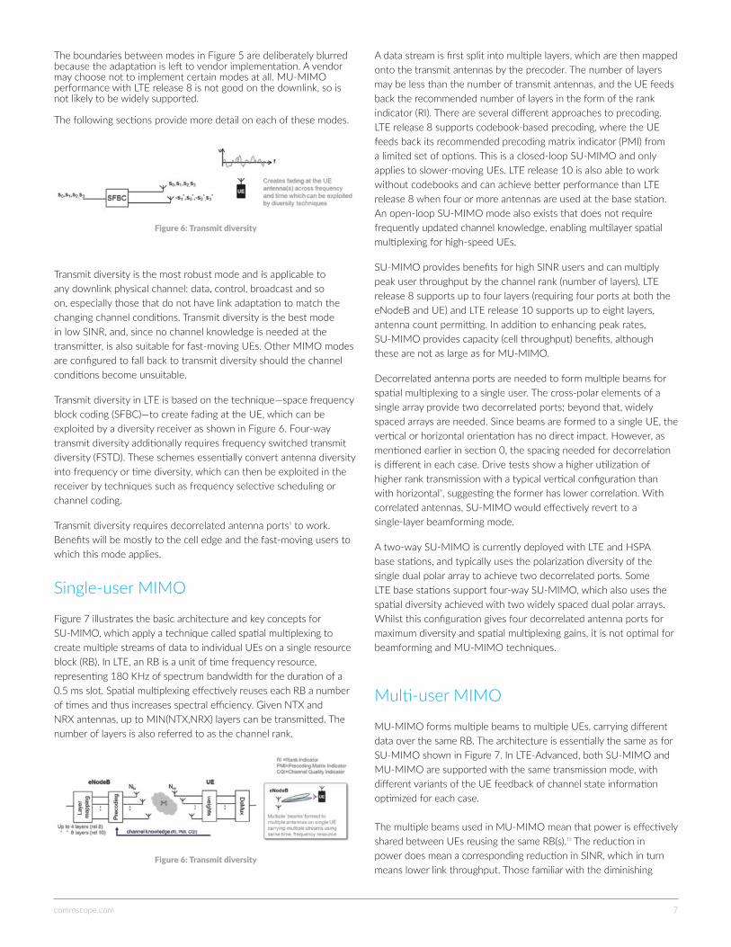
Transmit diversity is the most robust mode and is applicable to any downlink physical channel: data, control, broadcast and so on, especially those that do not have link adaptation to match the changing channel conditions. Transmit diversity is the best mode in low SINR, and, since no channel knowledge is needed at the transmitter, is also suitable for fast-moving UEs. Other MIMO modes are configured to fall back to transmit diversity should the channel conditions become unsuitable.
Transmit diversity in LTE is based on the technique—space frequency block coding (SFBC)—to create fading at the UE, which can be exploited by a diversity receiver as shown in Figure 6. Four-way transmit diversity additionally requires frequency switched transmit diversity (FSTD). These schemes essentially convert antenna diversity into frequency or time diversity, which can then be exploited in the receiver by techniques such as frequency selective scheduling or channel coding.
Transmit diversity requires decorrelated antenna ports5 to work. Benefits will be mostly to the cell edge and the fast-moving users to which this mode applies.
Single-user MIMO
Figure 7 illustrates the basic architecture and key concepts for SU-MIMO, which apply a technique called spatial multiplexing to create multiple streams of data to individual UEs on a single resource block (RB). In LTE, an RB is a unit of time frequency resource, representing 180 KHz of spectrum bandwidth for the duration of a 0.5 ms slot. Spatial multiplexing effectively reuses each RB a number of times and thus increases spectral efficiency. Given NTX and NRX antennas, up to MIN(NTX,NRX) layers can be transmitted. The number of layers is also referred to as the channel rank.
Figure6:Transmitdiversity
Figure6:Transmitdiversity
commscope.com 8
returns shape of the Shannon bound will know that, at low SINR, the relationship between SINR and spectral efficiency is linear, thus halving the SINR halves the spectral efficiency. Since MU-MIMO effectively shares power between multiple users, there is no net throughput benefit to MU-MIMO sharing at low SINR. At high SINR, however, halving the power has a much smaller impact on spectral efficiency. Thus the benefits of MU-MIMO are realized for UEs with medium-high SINR.15
MU-MIMO can work with single-antenna UEs, which can be agnostic to the use of MU-MIMO by the eNodeB. This is an important feature, as the network operator only needs to implement the MU-MIMO at the eNodeB and the benefits will be achieved immediately, without needing to wait years for supporting devices to come into circulation. As such, MU-MIMO was demonstrated early on for the LTE release 8 uplink. A basic downlink version is implemented in LTE release 8, but performance is significantly improved in LTE release 10 with new reference signal design, non-codebook precoding and UE feedback to enable fine beam adjustment. Since this is another closed-loop mode, it works best with low-speed nomadic UEs with continuous data downloads.
The main benefit of MU-MIMO is to cell capacity. With two arrays, each RB could potentially be used twice (given sufficient UE SINR), potentially doubling capacity. We note that SU-MIMO and MU-MIMO can be used simultaneously in combination. For example, the eNodeB may serve two UEs, each with two spatial layers5. The UEs need multiple antennas themselves to receive more than one spatial layer.
Unlike transmit diversity and SU-MIMO, best performance with MU-MIMO is achieved with correlated antennas, which require only slowly varying phase slope precoding to steer beams to different users.
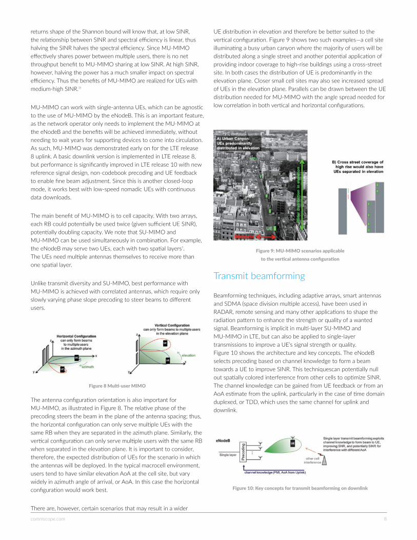
The antenna configuration orientation is also important for MU-MIMO, as illustrated in Figure 8. The relative phase of the precoding steers the beam in the plane of the antenna spacing; thus, the horizontal configuration can only serve multiple UEs with the same RB when they are separated in the azimuth plane. Similarly, the vertical configuration can only serve multiple users with the same RB when separated in the elevation plane. It is important to consider, therefore, the expected distribution of UEs for the scenario in which the antennas will be deployed. In the typical macrocell environment, users tend to have similar elevation AoA at the cell site, but vary widely in azimuth angle of arrival, or AoA. In this case the horizontal configuration would work best.
There are, however, certain scenarios that may result in a wider
UE distribution in elevation and therefore be better suited to the vertical configuration. Figure 9 shows two such examples—a cell site illuminating a busy urban canyon where the majority of users will be distributed along a single street and another potential application of providing indoor coverage to high-rise buildings using a cross-street site. In both cases the distribution of UE is predominantly in the elevation plane. Closer small cell sites may also see increased spread of UEs in the elevation plane. Parallels can be drawn between the UE distribution needed for MU-MIMO with the angle spread needed for low correlation in both vertical and horizontal configurations.
Transmit beamforming
Beamforming techniques, including adaptive arrays, smart antennas and SDMA (space division multiple access), have been used in RADAR, remote sensing and many other applications to shape the radiation pattern to enhance the strength or quality of a wanted signal. Beamforming is implicit in multi-layer SU-MIMO and MU-MIMO in LTE, but can also be applied to single-layer transmissions to improve a UE’s signal strength or quality. Figure 10 shows the architecture and key concepts. The eNodeB selects precoding based on channel knowledge to form a beam towards a UE to improve SINR. This techniquescan potentially null out spatially colored interference from other cells to optimize SINR. The channel knowledge can be gained from UE feedback or from an AoA estimate from the uplink, particularly in the case of time domain duplexed, or TDD, which uses the same channel for uplink and downlink.
Figure8Multi-userMIMO
Figure9:MU-MIMOscenariosapplicable totheverticalantennaconfiguration
Figure10:Keyconceptsfortransmitbeamformingondownlink
commscope.com 9
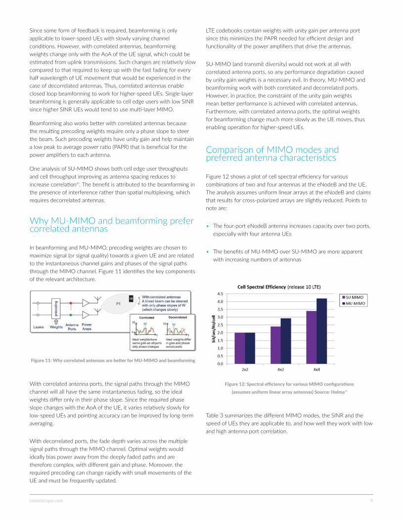
Since some form of feedback is required, beamforming is only applicable to lower-speed UEs with slowly varying channel conditions. However, with correlated antennas, beamforming weights change only with the AoA of the UE signal, which could be estimated from uplink transmissions. Such changes are relatively slow compared to that required to keep up with the fast fading for every half wavelength of UE movement that would be experienced in the case of decorrelated antennas. Thus, correlated antennas enable closed loop beamforming to work for higher-speed UEs. Single-layer beamforming is generally applicable to cell edge users with low SINR since higher SINR UEs would tend to use multi-layer MIMO.
Beamforming also works better with correlated antennas because the resulting precoding weights require only a phase slope to steer the beam. Such precoding weights have unity gain and help maintain a low peak to average power ratio (PAPR) that is beneficial for the power amplifiers to each antenna.
One analysis of SU-MIMO shows both cell edge user throughputs and cell throughput improving as antenna spacing reduces to increase correlation10. The benefit is attributed to the beamforming in the presence of interference rather than spatial multiplexing, which requires decorrelated antennas.
Why MU-MIMO and beamforming prefer correlated antennas
In beamforming and MU-MIMO, precoding weights are chosen to maximize signal (or signal quality) towards a given UE and are related to the instantaneous channel gains and phases of the signal paths through the MIMO channel. Figure 11 identifies the key components of the relevant architecture.
With correlated antenna ports, the signal paths through the MIMO channel will all have the same instantaneous fading, so the ideal weights differ only in their phase slope. Since the required phase slope changes with the AoA of the UE, it varies relatively slowly for low-speed UEs and pointing accuracy can be improved by long-term averaging.
With decorrelated ports, the fade depth varies across the multiple signal paths through the MIMO channel. Optimal weights would ideally bias power away from the deeply faded paths and are therefore complex, with different gain and phase. Moreover, the required precoding can change rapidly with small movements of the UE and must be frequently updated.
LTE codebooks contain weights with unity gain per antenna port since this minimizes the PAPR needed for efficient design and functionality of the power amplifiers that drive the antennas.
SU-MIMO (and transmit diversity) would not work at all with correlated antenna ports, so any performance degradation caused by unity gain weights is a necessary evil. In theory, MU-MIMO and beamforming work with both correlated and decorrelated ports. However, in practice, the constraint of the unity gain weights mean better performance is achieved with correlated antennas. Furthermore, with correlated antenna ports, the optimal weights for beamforming change much more slowly as the UE moves, thus enabling operation for higher-speed UEs.
Comparison of MIMO modes and preferred antenna characteristics
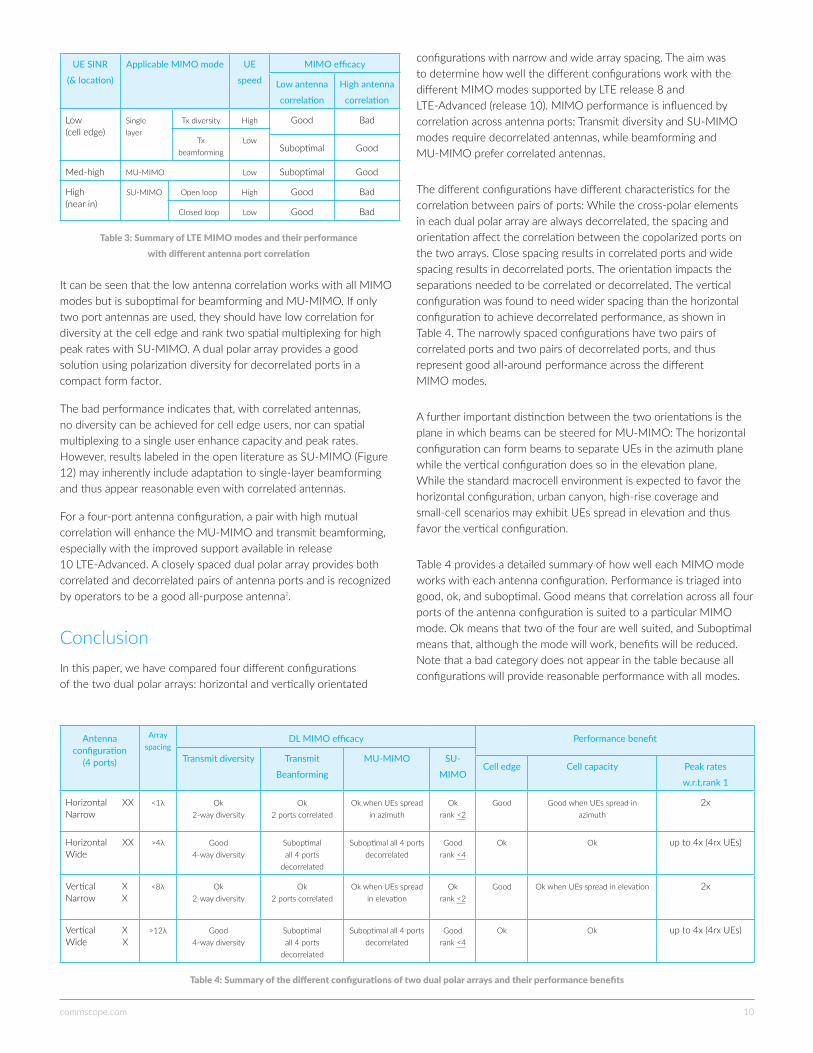
Figure 12 shows a plot of cell spectral efficiency for various combinations of two and four antennas at the eNodeB and the UE. The analysis assumes uniform linear arrays at the eNodeB and claims that results for cross-polarized arrays are slightly reduced. Points to note are:
• The four-port eNodeB antenna increases capacity over two ports, especially with four antenna UEs
• The benefits of MU-MIMO over SU-MIMO are more apparent with increasing numbers of antennas
Table 3 summarizes the different MIMO modes, the SINR and the speed of UEs they are applicable to, and how well they work with low and high antenna port correlation.
Figure11:WhycorrelatedantennasarebetterforMU-MIMOandbeamforming
Figure12:SpectralefficiencyforvariousMIMOconfigurations (assumesuniformlineararrayantennas)Source:Holma14
commscope.com 10
UE SINR
(& location)
Applicable MIMO mode UE
speed
MIMO efficacy
Low antenna
correlation
High antenna
correlation
Low (cell edge)
Single layer
Tx diversity High Good Bad
Tx beamforming
LowSuboptimal Good
Med-high MU-MIMO Low Suboptimal Good
High (near in)
SU-MIMO Open loop High Good Bad
Closed loop Low Good Bad
It can be seen that the low antenna correlation works with all MIMO modes but is suboptimal for beamforming and MU-MIMO. If only two port antennas are used, they should have low correlation for diversity at the cell edge and rank two spatial multiplexing for high peak rates with SU-MIMO. A dual polar array provides a good solution using polarization diversity for decorrelated ports in a compact form factor.
The bad performance indicates that, with correlated antennas, no diversity can be achieved for cell edge users, nor can spatial multiplexing to a single user enhance capacity and peak rates. However, results labeled in the open literature as SU-MIMO (Figure 12) may inherently include adaptation to single-layer beamforming and thus appear reasonable even with correlated antennas.
For a four-port antenna configuration, a pair with high mutual correlation will enhance the MU-MIMO and transmit beamforming, especially with the improved support available in release 10 LTE-Advanced. A closely spaced dual polar array provides both correlated and decorrelated pairs of antenna ports and is recognized by operators to be a good all-purpose antenna2.
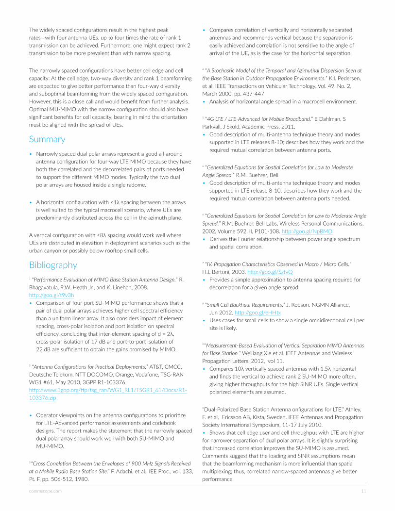
ConclusionIn this paper, we have compared four different configurations of the two dual polar arrays: horizontal and vertically orientated
configurations with narrow and wide array spacing. The aim was to determine how well the different configurations work with the different MIMO modes supported by LTE release 8 and LTE-Advanced (release 10). MIMO performance is influenced by correlation across antenna ports: Transmit diversity and SU-MIMO modes require decorrelated antennas, while beamforming and MU-MIMO prefer correlated antennas.
The different configurations have different characteristics for the correlation between pairs of ports: While the cross-polar elements in each dual polar array are always decorrelated, the spacing and orientation affect the correlation between the copolarized ports on the two arrays. Close spacing results in correlated ports and wide spacing results in decorrelated ports. The orientation impacts the separations needed to be correlated or decorrelated. The vertical configuration was found to need wider spacing than the horizontal configuration to achieve decorrelated performance, as shown in Table 4. The narrowly spaced configurations have two pairs of correlated ports and two pairs of decorrelated ports, and thus represent good all-around performance across the different MIMO modes.
A further important distinction between the two orientations is the plane in which beams can be steered for MU-MIMO: The horizontal configuration can form beams to separate UEs in the azimuth plane while the vertical configuration does so in the elevation plane. While the standard macrocell environment is expected to favor the horizontal configuration, urban canyon, high-rise coverage and small-cell scenarios may exhibit UEs spread in elevation and thus favor the vertical configuration.
Table 4 provides a detailed summary of how well each MIMO mode works with each antenna configuration. Performance is triaged into good, ok, and suboptimal. Good means that correlation across all four ports of the antenna configuration is suited to a particular MIMO mode. Ok means that two of the four are well suited, and Suboptimal means that, although the mode will work, benefits will be reduced. Note that a bad category does not appear in the table because all configurations will provide reasonable performance with all modes.
Table3:SummaryofLTEMIMOmodesandtheirperformance withdifferentantennaportcorrelation
Antenna configuration
(4 ports)
Array spacing
DL MIMO efficacy Performance benefit
Transmit diversity Transmit
Beanforming
MU-MIMO SU-
MIMOCell edge Cell capacity Peak rates
w.r.t.rank 1
Horizontal XX Narrow
<1λ Ok 2-way diversity
Ok 2 ports correlated
Ok when UEs spread in azimuth
Ok rank <2
Good Good when UEs spread in azimuth
2x
Horizontal XX Wide
>4λ Good 4-way diversity
Suboptimal all 4 ports
decorrelated
Suboptimal all 4 ports decorrelated
Good rank <4
Ok Ok up to 4x (4rx UEs)
Vertical X Narrow X
<8λ Ok 2-way diversity
Ok 2 ports correlated
Ok when UEs spread in elevation
Ok rank <2
Good Ok when UEs spread in elevation 2x
Vertical X Wide X
>12λ Good 4-way diversity
Suboptimal all 4 ports
decorrelated
Suboptimal all 4 ports decorrelated
Good rank <4
Ok Ok up to 4x (4rx UEs)
Table4:Summaryofthedifferentconfigurationsoftwodualpolararraysandtheirperformancebenefits
commscope.com 11
The widely spaced configurations result in the highest peak rates—with four antenna UEs, up to four times the rate of rank 1 transmission can be achieved. Furthermore, one might expect rank 2 transmission to be more prevalent than with narrow spacing.
The narrowly spaced configurations have better cell edge and cell capacity: At the cell edge, two-way diversity and rank 1 beamforming are expected to give better performance than four-way diversity and suboptimal beamforming from the widely spaced configuration. However, this is a close call and would benefit from further analysis. Optimal MU-MIMO with the narrow configuration should also have significant benefits for cell capacity, bearing in mind the orientation must be aligned with the spread of UEs.
Summary• Narrowly spaced dual polar arrays represent a good all-around antenna configuration for four-way LTE MIMO because they have both the correlated and the decorrelated pairs of ports needed to support the different MIMO modes. Typically the two dual polar arrays are housed inside a single radome.
• A horizontal configuration with <1λ spacing between the arrays is well suited to the typical macrocell scenario, where UEs are predominantly distributed across the cell in the azimuth plane.
A vertical configuration with <8λ spacing would work well where UEs are distributed in elevation in deployment scenarios such as the urban canyon or possibly below rooftop small cells.
Bibliography1 “Performance Evaluation of MIMO Base Station Antenna Design.” R. Bhagavatula, R.W. Heath Jr., and K. Linehan, 2008. http://goo.gl/t9v3h • Comparison of four-port SU-MIMO performance shows that a pair of dual polar arrays achieves higher cell spectral efficiency than a uniform linear array. It also considers impact of element spacing, cross-polar isolation and port isolation on spectral efficiency, concluding that inter-element spacing of d = 2λ, cross-polar isolation of 17 dB and port-to-port isolation of 22 dB are sufficient to obtain the gains promised by MIMO.
2 “Antenna Configurations for Practical Deployments.” AT&T, CMCC, Deutsche Telekom, NTT DOCOMO, Orange, Vodafone, TSG-RAN WG1 #61, May 2010, 3GPP R1-103376. http://www.3gpp.org/ftp/tsg_ran/WG1_RL1/TSGR1_61/Docs/R1-103376.zip
• Operator viewpoints on the antenna configurations to prioritize for LTE-Advanced performance assessments and codebook designs. The report makes the statement that the narrowly spaced dual polar array should work well with both SU-MIMO and MU-MIMO.
3 “Cross Correlation Between the Envelopes of 900 MHz Signals Received at a Mobile Radio Base Station Site.” F. Adachi, et al., IEE Proc., vol. 133, Pt. F, pp. 506-512, 1980.
• Compares correlation of vertically and horizontally separated antennas and recommends vertical because the separation is easily achieved and correlation is not sensitive to the angle of arrival of the UE, as is the case for the horizontal separation.
4 “A Stochastic Model of the Temporal and Azimuthal Dispersion Seen at the Base Station in Outdoor Propagation Environments.” K.I. Pedersen, et al, IEEE Transactions on Vehicular Technology, Vol. 49, No. 2, March 2000, pp. 437-447 • Analysis of horizontal angle spread in a macrocell environment.
5 “4G LTE / LTE-Advanced for Mobile Broadband.” E Dahlman, S Parkvall, J Skold, Academic Press, 2011. • Good description of multi-antenna technique theory and modes supported in LTE releases 8-10; describes how they work and the required mutual correlation between antenna ports.
6 “Generalized Equations for Spatial Correlation for Low to Moderate Angle Spread.” R.M. Buehrer, Bell • Good description of multi-antenna technique theory and modes supported in LTE release 8-10; describes how they work and the required mutual correlation between antenna ports needed.
6 “Generalized Equations for Spatial Correlation for Low to Moderate Angle Spread.” R.M. Buehrer, Bell Labs, Wireless Personal Communications, 2002, Volume 592, II, P101-108. http://goo.gl/NpBMD • Derives the Fourier relationship between power angle spectrum and spatial correlation.
7 “IV. Propagation Characteristics Observed in Macro / Micro Cells.” H.L Bertoni, 2003. http://goo.gl/SzfvQ • Provides a simple approximation to antenna spacing required for decorrelation for a given angle spread.
8 “Small Cell Backhaul Requirements.” J. Robson. NGMN Alliance, Jun 2012. http://goo.gl/eHHtx • Uses cases for small cells to show a single omnidirectional cell per site is likely.
9 “Measurement-Based Evaluation of Vertical Separation MIMO Antennas for Base Station.” Weiliang Xie et al. IEEE Antennas and Wireless Propagation Letters. 2012, vol 11. • Compares 10λ vertically spaced antennas with 1.5λ horizontal and finds the vertical to achieve rank 2 SU-MIMO more often, giving higher throughputs for the high SINR UEs. Single vertical polarized elements are assumed.
“Dual-Polarized Base Station Antenna onfigurations for LTE.” Athley, F. et al, Ericsson AB, Kista, Sweden. IEEE Antennas and Propagation Society International Symposium, 11-17 July 2010. • Shows that cell edge user and cell throughput with LTE are higher for narrower separation of dual polar arrays. It is slightly surprising that increased correlation improves the SU-MIMO is assumed. Comments suggest that the loading and SINR assumptions mean that the beamforming mechanism is more influential than spatial multiplexing; thus, correlated narrow-spaced antennas give better performance.

commscope.com 12
11 “Analysis of Incoming Wave Distribution in Vertical Plane in Urban Area and Evaluation of Base Station Antenna Effective Gain.” K. Kitao and T. Imai. IEICE Trans. Comm., June 2009, vol. E92-B, no. 6. • Gives vertical angle spreads of one to two degrees and reveals the interesting property of the vertical configuration—that correlation changes with UE range, near-in UEs result in higher correlation at the eNodeB antenna ports.
12 “The Seven Modes of MIMO in LTE.” Telesystem Innovations, 2009, http://goo.gl/g6RpN • Describes the different transmission modes supported in LTE release 8.
13 “LTE; Evolved Universal Terrestrial Radio Access (E-UTRA); Physical Layer Procedures.” 3GPP TS 36.213 version 10.5.0 (Release 10), March 2012. http://goo.gl/FYEKI • Specification that captures the downlink transmission modes.
14 “LTE for UMTS: Evolution to LTE Advanced.” Harri Holma, Antti Toskala, 2nd ed., Wiley, 2010 • Describes the double codebook feedback in LTE-Advanced, which enables good performance for both SU-MIMO and MU-MIMO. Provides performance comparison results of two- and our- antenna configurations with SU-MIMO and MU-MIMO.
15 “Downlink MIMO in LTE-Advanced: SU-MIMO vs. MU-MIMO.” Lingjia Liu et al, IEEE Communications Magazine. February 2012, vol 50 issue 2. • Detailed description of LTE-Advanced reference signals and codebooks to enhance SU-MIMO and MU-MIMO performance over LTE release 8. Shows that adaptation between these modes is essential for all-around performance.
16 “Latest Results from the LSTI,” J Robson, Feb 2009. http://goo.gl/Be5yZ • Shows field trial results of uplink MU-MIMO working in LTE release 8.
End notes* We note that although a single dual polar array unit may have many elements in the vertical plane, the relative phase excitation of these is generally fixed for a given elevation pattern and downtilt. The vertical elements are combined internally in the antenna unit and only the +45 degree and -45 degree polarizations are presented at the antenna connectors.
About the authorsKevin Linehan Vice president & chief technology officer, Antenna Systems, CommScope
Mr. Linehan’s responsibilities include the monitoring of wireless industry trends, technologies and standards as they relate to antenna technology and product development. Mr. Linehan is also responsible for the scouting, evaluation and introduction of emerging antenna systems technologies through collaborative innovation and strategic alliances.
Prior to assuming a strategic role at CommScope, his responsibilities have included management and design positions for base station antennas, terrestrial microwave antennas and earth station antennas.
He received a bachelor’s degree in electrical engineering from the University of Illinois at Champaign-Urbana, where he was a research assistant in the Electromagnetics Research Laboratory. He holds six patents for antenna design in the United States.
Julius Robson Independent wireless technology consultant
Mr. Robson specializes in LTE standards, small cell backhaul and network performance evaluation, helping his clients interpret, respond to and articulate the impact made by emerging wireless technologies. He has chaired a number of industry groups within the NGMN Alliance, including
the LTE/SAE Trial Initiative. Julius is currently the vice chair of the Small Cell Forum’s backhaul group. He previously spent 15 years conducting wireless technology research for Nortel as a system architect and delegate for 3GPP RAN standards.
commscope.comVisit our website or contact your local CommScope representative for more information.
© 2017 CommScope, Inc. All rights reserved.
All trademarks identified by ® or ™ are registered trademarks or trademarks, respectively, of CommScope, Inc. This document is for planning purposes only and is not intended to modify or supplement any specifications or warranties relating to CommScope products or services. CommScope is committed to the highest standards of business integrity and environmental sustainability, with a number of CommScope’s facilities across the globe certified in accordance with international standards, including ISO 9001, TL 9000, and ISO 14001. Further information regarding CommScope’s commitment can be found at www.commscope.com/About-Us/Corporate-Responsibility-and-Sustainability.
WP-106096.1 (02/17)
Everyone communicates. It’s the essence of the human experience. How we communicate is evolving. Technology is reshaping the way we live, learn and thrive. The epicenter of this transformation is the network—our passion. Our experts are rethinking the purpose, role and usage of networks to help our customers increase bandwidth, expand capacity, enhance efficiency, speed deployment and simplify migration. From remote cell sites to massive sports arenas, from busy airports to state-of-the-art data centers—we provide the essential expertise and vital infrastructure your business needs to succeed. The world’s most advanced networks rely on CommScope connectivity.