when an adjacent watershed inundates your offline
TRANSCRIPT

1 Copyright © 2017 U.S. Society on Dams. All Rights Reserved.
WHEN AN ADJACENT WATERSHED INUNDATES YOUR
OFFLINE RESERVOIR: UKUMEHAME RESERVOIR DAM REMOVAL
CHALLENGES AND DESIGN
Andrew J. Lynch, PE, CFM1
Stewart S. Vaghti, PE, CFM2
Dean B. Durkee, PhD, PE3
ABSTRACT
Ukumehame Reservoirs Nos. 2 & 3 are a pair of offline reservoirs impounded by earthen
embankments located on the island of Maui, Hawaii. The reservoirs were constructed
during Hawaii’s sugar plantation era as a part of a statewide network of reservoirs and
irrigation ditches to support local agriculture. In recent decades with the decline of sugar
production, these and similar reservoirs are often neglected and have fallen into disrepair.
The reservoirs are classified as high-hazard due to a residential structure immediately
downstream of the No. 3 embankment. In June 2008, a significant seep was discovered
at the toe of the No. 3 embankment. Following this discovery, the reservoirs were
drained and the dam owners decided to remove the reservoirs by breaching the
embankments.
Hydrologic and hydraulic analyses led to the discovery that the probable maximum flood
(PMF) within the adjacent stream overtops the embankments and inundates the
reservoirs. We were challenged with designing breach sections to accommodate flows
from the watersheds directly contributing to the reservoirs as well as flows from the
overbank of the adjacent stream considering what we had learned about the PMF.
To better understand this condition, a 1D unsteady HEC-RAS model was created to
simulate pre- and post-breach conditions. This analysis assisted in presenting the design
of the reservoir removal to the owner and the State Dam Safety Division. A 2D
HEC-RAS model was subsequently prepared for comparison with the 1D HEC-RAS
model and the 2D model agreed with the conclusions drawn from the 1D model.
INTRODUCTION
History
Beginning approximately 180 years ago, sugar plantations and farming became a
significant and integral part of the economy of the Hawaiian Islands. The first
commercially successful sugarcane plantation was founded in Koloa on the island of
Kaua’i in 1835 (U.S. National Park Service). Commercial production of sugar quickly
grew to outpace the manpower of the local islanders, and beginning in 1850, foreign
laborers from China and Japan were imported to meet the demand.
1 Project Engineer, Gannett Fleming, Phoenix, AZ 85012, [email protected] 2 Senior Project Manager, Gannett Fleming, Phoenix, AZ 85012, [email protected] 3 Vice President, Gannett Fleming, Phoenix, AZ 85012, [email protected]

2 Copyright © 2017 U.S. Society on Dams. All Rights Reserved.
As the production of sugarcane continued to increase, the Hawaiian Islands underwent
significant transformation in order to meet the demands created by the new industry.
Island-wide networks of ditches, tunnels, canals and reservoirs were constructed in order
to intercept, store and deliver rainfall runoff to the sugarcane fields. The irrigation
network was so successful that it enabled cultivation on the leeward side of the islands,
which are much drier than the opposite windward side.
The transformation of the local drainage patterns came at significant cost to native
Hawaiians, who were powerless to stop the loss of a resource that they depended on for
their own agricultural uses. Historically, Hawaiians were self-sufficient, relying for
centuries on the cultivation of, among other things, the kalo (Hawaiian for taro) plant.
Kalo, similar to sugarcane, requires a large amount of water for cultivation and the
production of taro reduced drastically due to the rise of sugarcane farming.
Sugar production in Hawaii has been in decline since the 1970s. Despite having once
been the primary economic driver for the state of Hawaii, the final remaining
commercial-scale sugar farm ceased operations on December 12, 2016 (Associated
Press).
Project Background
Ukumehame Reservoirs Nos. 2 & 3 are situated on the southwestern side of Maui,
approximately 8 miles southeast of the city of Lahaina (see Figure 1). The reservoirs and
the adjacent Ukumehame Ditch were constructed in 1905 (Wadsworth) by the Honolua
Ranch & Pioneer Mill Company.
Figure 1 Island of Maui, HI
The reservoirs are side-by-side, offline reservoirs which are situated within Ukumehame
Gulch and immediately adjacent to the main stream channel centerline (see Figure 2),
which runs along the southeastern side of the reservoirs and discharges into the Pacific

3 Copyright © 2017 U.S. Society on Dams. All Rights Reserved.
Ocean approximately 0.8 miles away. The reservoirs were historically filled by directing
water from the manmade Auwai Ditch (which runs along the right slope of the
Ukumehame Gulch, looking downstream) into the reservoirs by way of a diversion
structure.
Due to the existence of a residence immediately downstream of the Reservoir No. 3
embankment and active residential construction between the dams and the ocean outfall
from the stream, the reservoirs are classified as high-hazard, meaning that the failure of
one or both of the embankments could result in probable loss of human life and
significant property damage.
Figure 2 Project Location Map (imagery source: Google Earth)
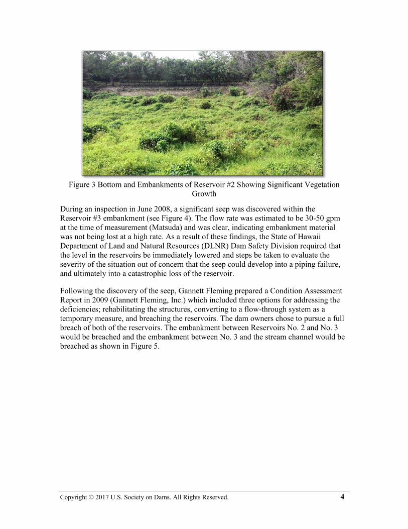
The original areas of active sugar cultivation have been abandoned and sold off for
residential construction. It is unclear how long the reservoirs were actively in use
providing irrigation water to the sugar plantations; however, in recent decades, and with
the decline of sugar production on the island, the reservoirs have fallen into disrepair with
significant vegetation growing on the embankment slopes and within the reservoir
bottoms (see Figure 3).
4 Copyright © 2017 U.S. Society on Dams. All Rights Reserved.
Figure 3 Bottom and Embankments of Reservoir #2 Showing Significant Vegetation
Growth
During an inspection in June 2008, a significant seep was discovered within the
Reservoir #3 embankment (see Figure 4). The flow rate was estimated to be 30-50 gpm
at the time of measurement (Matsuda) and was clear, indicating embankment material
was not being lost at a high rate. As a result of these findings, the State of Hawaii
Department of Land and Natural Resources (DLNR) Dam Safety Division required that
the level in the reservoirs be immediately lowered and steps be taken to evaluate the
severity of the situation out of concern that the seep could develop into a piping failure,
and ultimately into a catastrophic loss of the reservoir.
Following the discovery of the seep, Gannett Fleming prepared a Condition Assessment
Report in 2009 (Gannett Fleming, Inc.) which included three options for addressing the
deficiencies; rehabilitating the structures, converting to a flow-through system as a
temporary measure, and breaching the reservoirs. The dam owners chose to pursue a full
breach of both of the reservoirs. The embankment between Reservoirs No. 2 and No. 3
would be breached and the embankment between No. 3 and the stream channel would be
breached as shown in Figure 5.

5 Copyright © 2017 U.S. Society on Dams. All Rights Reserved.
Figure 4 Seep Discharging from the Toe of the Reservoir #3 Embankment
Figure 5 Proposed Breach Design
HAWAII DAM SAFETY REGULATIONS
The basis for our analysis and design is Hawaii Administrative Rules Chapter 13-190.1.
These rules provide design and analysis requirements based on size and hazard
classification. Because the Condition Assessment Report included both a rehabilitation
and a breach alternative, we evaluated both the PMF and the 100-year floods for this
study. The rules state that all high-hazard dams, regardless of height or capacity, shall be

6 Copyright © 2017 U.S. Society on Dams. All Rights Reserved.
able to pass the full PMF without overtopping the embankments (Hawaii Department of
Land and Natural Resources §13-190.1-4(c)). In the event that the reservoirs would have
been rehabilitated, this rule would apply. The rules also state that for removal an
embankment shall be breached to allow passage of the 100-year flood with a maximum
depth of five feet anywhere within the breached channel section (§13-190.1-21(b)(2));
this rule provided the basis for the breach design.
HYDRAULIC ANALYSIS
Model Setup
We had determined during the hydrologic and hydraulic analyses for the Condition
Assessment Report that the PMF within Ukumehame Gulch overtops the embankments
and inundates the reservoirs while the 100-year flow remains within the main stream
channel. Even though we were proposing to breach the embankments and were therefore
only required to evaluate the passage of the 100-year storm event, DLNR Dam Safety
requested that we analyze the PMF condition passing through the breaches and determine
the maximum depth of flow within the reservoirs. The concern was expressed that the
remaining embankments could detain some volume of water, however briefly, which may
still pose a risk to the downstream residence.
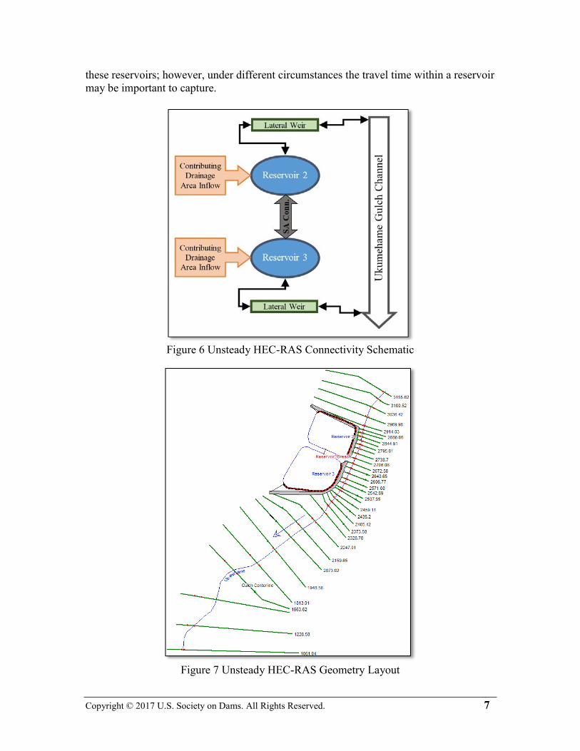
We determined that an unsteady HEC-RAS model would be necessary to model the
various interrelated parts, such as differential timing of the incoming hydrographs, effects
due to the storage capacity of the reservoirs, etc. The following model configuration was
developed:
• The Ukumehame Gulch is modeled by 34 cross sections cut from a recent survey.
All HEC-RAS geometry was cut and exported from Civil 3D 2014.
• The north and east sides of Reservoir 2 are modeled with a lateral weir structure
that can exchange flows back and forth with the stream channel.
• The south and east sides of Reservoir 3 are modeled with a separate lateral weir
structure that can exchange flows back and forth with the stream channel. This
lateral weir reflects the geometry of the proposed breach.
• Reservoirs 2 and 3 are each modeled as storage areas with independent stage-
storage relationships.
• Reservoirs 2 and 3 each have directly contributing inflow hydrographs from the
previous hydrologic analysis.
• Reservoirs 2 and 3 are connected to each other by way of a storage area
connection. The cross section of the storage area connection reflects the proposed
breach between Reservoirs 2 and 3.
A schematic of the model and a graphic of the HEC-RAS geometry file are shown in
Figure 6 and Figure 7, respectively. It is important to note that the lateral weirs and the
storage area connection allow both positive and negative flow. Also, because HEC-RAS
calculates the storage areas using level pool routing, there is no time delay between flows
entering and leaving a storage area. This is not a significant issue due to the small size of
7 Copyright © 2017 U.S. Society on Dams. All Rights Reserved.
these reservoirs; however, under different circumstances the travel time within a reservoir
may be important to capture.
Figure 6 Unsteady HEC-RAS Connectivity Schematic
Figure 7 Unsteady HEC-RAS Geometry Layout
8 Copyright © 2017 U.S. Society on Dams. All Rights Reserved.
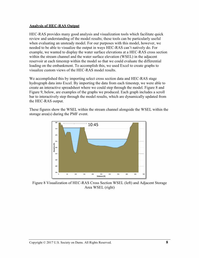
Analysis of HEC-RAS Output
HEC-RAS provides many good analysis and visualization tools which facilitate quick
review and understanding of the model results; these tools can be particularly useful
when evaluating an unsteady model. For our purposes with this model, however, we
needed to be able to visualize the output in ways HEC-RAS can’t natively do. For
example, we wanted to display the water surface elevations at a HEC-RAS cross section
within the stream channel and the water surface elevation (WSEL) in the adjacent
reservoir at each timestep within the model so that we could evaluate the differential
loading on the embankment. To accomplish this, we used Excel to create graphs to
visualize custom views of the HEC-RAS model results.
We accomplished this by importing select cross section data and HEC-RAS stage
hydrograph data into Excel. By importing the data from each timestep, we were able to
create an interactive spreadsheet where we could step through the model. Figure 8 and
Figure 9, below, are examples of the graphs we produced. Each graph includes a scroll
bar to interactively step through the model results, which are dynamically updated from
the HEC-RAS output.
These figures show the WSEL within the stream channel alongside the WSEL within the
storage area(s) during the PMF event.
Figure 8 Visualization of HEC-RAS Cross Section WSEL (left) and Adjacent Storage
Area WSEL (right)

9 Copyright © 2017 U.S. Society on Dams. All Rights Reserved.
Figure 9 Visualization of HEC-RAS Stream Profile WSEL (dashed line / light blue) and
Adjacent Storage Areas WSEL (solid line / dark blue)
Results of the Analysis
As stated above, the concern expressed by Hawaii DLNR was the potential for the
remnant embankment to fail during the PMF, and the sudden release of any
temporarily-impounded water. The graphical representations shown above indicate that
for the majority of the flow event, the WSEL within the stream channel is higher than the
WSEL within the reservoirs. This implies that if any failure were to occur, it would more
likely be the embankment failing into the reservoirs and not the other way around.
We presented these results to Hawaii DLNR over web conference. We were able to
demonstrate that even during the PMF, the depth and volume within the reservoirs does
not appear to create a condition where the remnant embankments could fail and release a
surge of water into the downstream reach. With the concurrence of Hawaii DLNR, we
proceeded to complete the breach design based on the 100-year inflows from the
upstream watersheds only.
Comparison to 2D HEC-RAS Model
Following the completion of the design and the then-recent release of HEC-RAS 5.0 with
2D modeling, we created a comparison model. The 2D grid was created from data
exported from our Civil 3D design surface, and the inflow hydrographs used in the 1D
model are identical to those used within the 2D model. The maximum WSEL within the
reservoirs matched within a reasonable level, and the results predicted by the 1D model
are reflected within the 2D model. Figure 10 shows a snapshot of the 2D modeling
results. This graphic depicts the greater depths within the channel section (darker blue)
compared to the depths within the adjacent reservoir.

10 Copyright © 2017 U.S. Society on Dams. All Rights Reserved.
Figure 10 Graphical Output of 2D HEC-RAS Model results
Recommendation for Additional Investigation
The 2D HEC-RAS model has not been advanced beyond the initial comparative analyses
described above. In the future, this model can be updated with additional detail such as
spatially variable roughness and refinement of the two dimensional grid. While it is not
expected for the results to match precisely between the 1D and 2D models, close
agreement will lend credibility to the initial one dimensional analysis performed for this
project.
CULTURAL SENSITIVITY
Immediately to the north of Reservoir No. 2 sits a lo'i, or a kalo patch, which is still being
cultivated to this day. This lo'i is accessed by crossing the Reservoir Nos. 2 and 3
embankments and is owned by the family of Ekolu Lindsey, who continues the centuries-
old tradition of cultivating kalo.

11 Copyright © 2017 U.S. Society on Dams. All Rights Reserved.
Figure 11 Lo'i (foreground) next to Reservoir #2 (background, prior to draining)
(Maui Cultural Lands - used with permission)
The existence and maintenance of this lo'i is very important to preserve a part of the
Hawaiian heritage. In recognizing this importance, we took additional steps in the
preparation of the design and construction documents in order to prevent disturbance of
this valuable piece of land, to maintain the water source from the nearby ditch, and to
maintain access for the local residents who care for it. These steps may also include
informing local community members at a public forum of the planned construction
activities and revegetating the disturbed areas with a seed mixture of only native grasses
and plants. We are conscious of what can be a delicate situation and want to strike an
appropriate balance between the need to remedy the deficient dam and public safety
hazard, and the need to preserve Hawaii’s natural resources for those who cherish them.
CONCLUSION
Following the discovery of a dam safety issue at Ukumehame Reservoir Nos. 2 & 3, we
were presented with a unique opportunity and challenge. This project required some
understanding of the local culture and history, and sensitivity to the needs of DLNR, our
client and the local residents.
The analysis of the Ukumehame Reservoirs was a bit atypical; offline reservoirs which
nonetheless receive a substantial inflow volume from an adjacent stream. A concern was
expressed that, even though the embankments were to be breached, could the capacity of
the breached section restrict flows as they pass through the reservoir? And if so, could a
failure of the remnant embankments during a flood event release a surge of water and still
pose a threat to people or property downstream? In order to understand this situation, an
unsteady HEC-RAS model was created which allowed us to understand the how flows
within the main stream and reservoirs relate. This allowed us to suggest that a failure of
the remnant embankments would likely not release a surge of water downstream because
the reservoir WSEL is lower than the adjacent stream WSEL for the majority of the flow
duration.

12 Copyright © 2017 U.S. Society on Dams. All Rights Reserved.
Additionally, this project required sensitivity to other, non-technical issues such as the
cultural and historical significance of the project area, and how the proposed
modifications to the reservoirs will impact the local residents. For this project to be a
success once construction is complete, it will require more than a design which simply
addresses the need to breach the reservoirs; it will require reaching out to local residents,
educating them about the project, learning about their concerns and preparing into a
design which does its best to satisfy the needs of those involved.
ACKNOWLEDGEMENTS
Thank you to Mark Lake for contributing to the project background by coming through
on records requests and thank you to Ekolu Lindsey for sharing insights into the cultural
importance of the Ukumehame Reservoirs and your personal experiences with the
adjacent lo'i.
REFERENCES
Alexander & Baldwin, Inc. Alexander & Baldwin Announces Transition Of Hawaiian
Commercial & Sugar Company To A Diversified Farm Model. 6 January 2016. 03
October 2016. <http://phx.corporate-ir.net/phoenix.zhtml?c=85663&p=irol-
newsArticle&ID=2127059>.
Associated Press. "End of an era: Hawaii's last sugar mill wraps up final harvest."
Honolulu: Honolulu Star-Advertiser, 12 December 2016.
<http://www.staradvertiser.com/2016/12/12/business/business-breaking/end-of-an-era-
hawaiis-last-sugar-mill-wraps-up-final-harvest/>.
Gannett Fleming, Inc. "Condition Assessment Report - Ukumehame Reservoir Nos. 2 &
3." April 2009.
Hawaii Department of Land and Natural Resources. "Hawaii Administrative Rules
chapter 13-190.1." Honolulu, 14 March 2012.
Matsuda, Edwin, et al. "State of Hawaii - DLNR Dam Safety Inspection Sheet for
Ukumehame Reservoirs." Dam Inspection Report. June 16, 2008.
Maui Cultural Lands. Ukumehame. 2015.
<http://mauiculturallands.org/projects/ukumehame>.
U.S. National Park Service. Old Sugar Mill of Koloa. n.d. 03 October 2016.
<https://www.nps.gov/nr/travel/Asian_American_and_Pacific_Islander_Heritage/Old-
Sugar-Mill-of-Koloa.htm>.
Wadsworth, Harold Anderson. "Irrigation Census of Hawaii with some Comparisons
with Continental United States." Hawaiian Sugar Planters' Association. Honolulu:
Advertiser Publishing Co., Ltd., 1935.