wht isis control system user guide physics and astronomy research council isaac newton group wht...
TRANSCRIPT
Particle Physics and Astronomy
Research Council
Isaac Newton Group
WHT ISIS Control System User GuideVersion : 1.1
Document Identifier : whtisis14
20 October 2005
Isaac Newton Group,Apartado 321, 38780 S/C La Palma, Tenerife, Canary Islands
Telephone +34 922 425425 Fax +34 922 425401Email [email protected]
whtisis14 WHT ISIS Control User Guide
Table of Contents
CHAPTER 1 INTRODUCTION.........................................................................6
CHAPTER 2 GLOSSARY................................................................................7
2.1 MIMIC.............................................................................................................................7
2.2 GUI...................................................................................................................................7
2.3 Cassgrain Acquisition and Guidance Box....................................................................7
2.4 4MS ..................................................................................................................................7
2.5 Filter management system..............................................................................................7
2.6 Controls............................................................................................................................7
CHAPTER 3 COMMAND LINE SCRIPTS........................................................9
3.1 Online Help Information................................................................................................9
3.2 Error reports...................................................................................................................9
3.3 The bcoll command.........................................................................................................9
3.4 The bfilta command........................................................................................................9
3.5 The bfiltb command......................................................................................................10
3.6 The bfold command......................................................................................................10
3.7 The bgrat command......................................................................................................10
3.8 The bhart command......................................................................................................10
3.9 The cenwave command.................................................................................................11
3.10 The change command.................................................................................................11
3.11 The dekker command ................................................................................................11
3.12 The imageslicer command..........................................................................................12
3.13 The inbcoll command .................................................................................................12
– 2 –
whtisis14 WHT ISIS Control User Guide
3.14 The inbfold command ................................................................................................12
3.15 The inbg command .....................................................................................................12
3.16 The indek command ...................................................................................................12
3.17 The infcp command.....................................................................................................12
3.18 The inrcoll command..................................................................................................12
3.19 The inrfold command.................................................................................................13
3.20 The inrg command .....................................................................................................13
3.21 The inslit command ....................................................................................................13
3.22 The isis command .......................................................................................................13
3.23 The isis_begin command ............................................................................................13
3.24 The isis_change_filter command...............................................................................13
3.25 The isis_config command ..........................................................................................13
3.26 The isis_end command ...............................................................................................14
3.27 The isis_filters command ...........................................................................................14
3.28 The isis_init command ...............................................................................................14
3.29 The isis_move command ............................................................................................15
3.30 The isis_reprogram command...................................................................................17
3.31 The isis_stop command...............................................................................................18
3.32 The isis_update command .........................................................................................18
3.33 The longslit command ................................................................................................18
3.34 The mslit command ....................................................................................................18
3.35 The rcoll command.....................................................................................................18
3.36 The rfilta command.....................................................................................................19
3.37 The rfiltb command....................................................................................................19
– 3 –
whtisis14 WHT ISIS Control User Guide
3.38 The rfold command.....................................................................................................19
3.39 The rgrat command....................................................................................................19
3.40 The rhart command....................................................................................................20
3.41 The setdichroic command ..........................................................................................20
3.42 The setgrating command ...........................................................................................20
3.43 The setgratingoffset command ..................................................................................21
3.44 The setgratingorder command ..................................................................................21
3.45 The slit command .......................................................................................................21
3.46 The slit_door command..............................................................................................22
3.47 The slitarc command ..................................................................................................22
CHAPTER 4 ISIS AND A&G GUI CONTROL APPLICATION......................23
4.1 Starting the GUI ...........................................................................................................23
4.2 Colour Coding...............................................................................................................23
4.3 Icons................................................................................................................................23
4.4 The ISIS Engineering Panel.........................................................................................244.4.1 The Global Status & Control Section.......................................................................25
4.4.1.1 The 4MS Monitor Mode Control.......................................................................254.4.1.2 The Slit Door Control........................................................................................254.4.1.3 The Update Filters Control................................................................................254.4.1.4 The Update All Status Control ..........................................................................254.4.1.5 The Stop All Mechanisms Control....................................................................254.4.1.6 The Reset Controller Control.............................................................................264.4.1.7 The Last 4MS Response Status Label...............................................................26
4.4.2 The ISIS Control Panel.............................................................................................274.4.2.1 The Filter Controls.............................................................................................284.4.2.2 The Blue Fold Control.......................................................................................284.4.2.3 The Red Fold Control........................................................................................284.4.2.4 The Hartmann Shutter Controls.........................................................................284.4.2.5 The Slit Unit Control.........................................................................................294.4.2.6 The FCP Tray Control.......................................................................................294.4.2.7 The Collimator Position Controls......................................................................29
– 4 –
whtisis14 WHT ISIS Control User Guide
4.4.2.8 The Grating Position Controls...........................................................................294.4.2.9 The Slitwidth Control........................................................................................294.4.2.10 The Dekker Control.........................................................................................304.4.2.11 The Grating Specifier Controls.......................................................................30
4.5 The ISIS Observer Control Panel................................................................................304.5.1 ISIS Related controls................................................................................................30
4.5.1.1 The slitwidth Control ........................................................................................314.5.1.2 The cenwave Controls.......................................................................................31
4.5.2 The A&G Mechanism Controls................................................................................314.5.2.1 The Comparison Lamps ND Setting Control ...................................................314.5.2.2 The AUX Filter Control.....................................................................................314.5.2.3 The Main Colour Filter Control.........................................................................324.5.2.4 The Main ND Filter Control..............................................................................324.5.2.5 The Lamps Control............................................................................................324.5.2.6 The Mirror Control............................................................................................32
– 5 –

whtisis14 WHT ISIS Control User Guide
Chapter 1 IntroductionThe purpose of this document is to provide a user guide to the ISIS control system which is hosted upon the W. H. T. instrument control system. It outlines the syntax and the semantics of the command line scripts which can be used to retrieve status or effect control over the mechanisms which constitute the ISIS spectrograph. It also describes the use of the graphical control application which can be used to coordinate the operation of the ISIS instrument.
The intended target audience of this document is the observer who will have to use the system operationally and the operations team engineers.
– 6 –
whtisis14 WHT ISIS Control User Guide
Chapter 2 GlossaryThis section contains a glossary of the terms which are used throughout the document.
2.1 MIMICA MIMIC is graphical representation of a system which updates in realtime to continually reflect the current state of the underlying hardware system. There are many applications for such an application at the observatory, much of the hardware deployed at the ING benefits from a graphical representation of it’s state.
2.2 GUIA graphica l in te r face which wi l l permi t the user to cont ro l the mechan isms which compr ise the IS IS 4MS sys tem in add i t ion to r epor t ing s ta tus a ssoc ia ted wi th the 4MS microprocessor .
2.3 Cassgrain Acquisition and Guidance BoxThe Cassegrain acquisition and guidance box (CAGB) is an instrument which is physically located above the ISIS instrument and is used in conjunction with the ISIS spectrograph during nighttime science operations. A user guide to the system is provided in the document [WHTCAGB6].
2.4 4MS The mechanisms associated with the acquisition and guidance system are controlled by a 4MS embedded microprocessor system which is FORTH based. Communication between the highlevel software control system and the embedded system is via a RS232 serial communications link.
2.5 Filter management systemThis is a database based system which is used to track the locations of all of the filters which are currently being used at the ING. Supports astronomers have the responsibility of ensuring that for each filter mechanism associated with the ISIS and CAGB instrumentation, the details of the filters which are located in those mechanisms is accurate and uptodate.
For more information relating to the filter management system refer to the document [WHTFILTDB2]
2.6 ControlsIn the context of the graphical user interface, a control is a graphical device upon the interface which can be used to effect control over some aspect of the acquisition and guidance
– 7 –

whtisis14 WHT ISIS Control User Guide
4MS system. These can take many different forms depending on the intended function of the control.
– 8 –

whtisis14 WHT ISIS Control User Guide
Chapter 3 Command line scriptsThis chapter outlines the various command line based scripts which can be used from the instrument control system console (normally the whtics machine) to control components of the ISIS spectrograph.
3.1 Online Help InformationAll of the commands listed in this chapter honour the h option which when specified, will result in help information for the command being printed on the console.
3.2 Error reportsAny errors which are encountered by the ISIS system in response to a request from one of the command line scripts will be duly relayed back to the console and the talker log.
On successful completion of a command line script, the script will return a status of 0. Any other status value returned should be considered an error status.
Status relating to the progress of the commands will be sent to the talker log so there is a permanent record of what actions have been performed upon the ISIS system.
3.3 The bcoll commandThis command can be used to position the collimator on the blue arm. The syntax of the command is as follows;
bcoll <demanded position>
The position should be specified in units of microns and be in the range of 0 to 52000.
3.4 The bfilta commandThis command can be used to select a filter in the blue filter A mechanism. The syntax of the command is as follows :
bfilta <filter name|filter position>
Should the filter position be specified, it should be in the range of 1 to 3. Alternatively the user may specify the name of the filter in the filter mechanism. The name should correspond with the names of one of the filters which have been specified in the filter management system for this specific filter mechanism.
– 9 –
whtisis14 WHT ISIS Control User Guide
3.5 The bfiltb commandThis command can be used to select a filter in the blue filter B mechanism. The syntax of the command is as follows :
bfiltb <filter name|filter position>
Should the filter position be specified, it should be in the range of 1 to 3. Alternatively the user may specify the name of the filter in the filter mechanism. The name should correspond with the names of one of the filters which have been specified in the filter management system for this specific filter mechanism.
3.6 The bfold commandThe bfold command can be used to control the blue fold mechanism. The syntax of the command is as follows :
bfold <position>
The position can be specified either in engineering units in the range of 0..2 or the user may specify one of the three logical positions :
• Clear
• Mirror
• Dichroic
3.7 The bgrat commandThe bgrat command can be used to position the blue grating mechanism.
The syntax of the command is as follows :
bgrat <position>
The desired position of the grating should be specified in units of 0.01 degrees. This command is principally an engineering command. The Observer should set the central wavelength for the blue arm using the cenwave command (see 3.9).
3.8 The bhart commandThe bhart command can be used to control the blue Hartmann shutters.
The syntax of the command is as follows :
bhart <demanded position>
The position can be specified using an engineering value in the range of 0..2 or by specifying one of the following logical values :
– 10 –
whtisis14 WHT ISIS Control User Guide
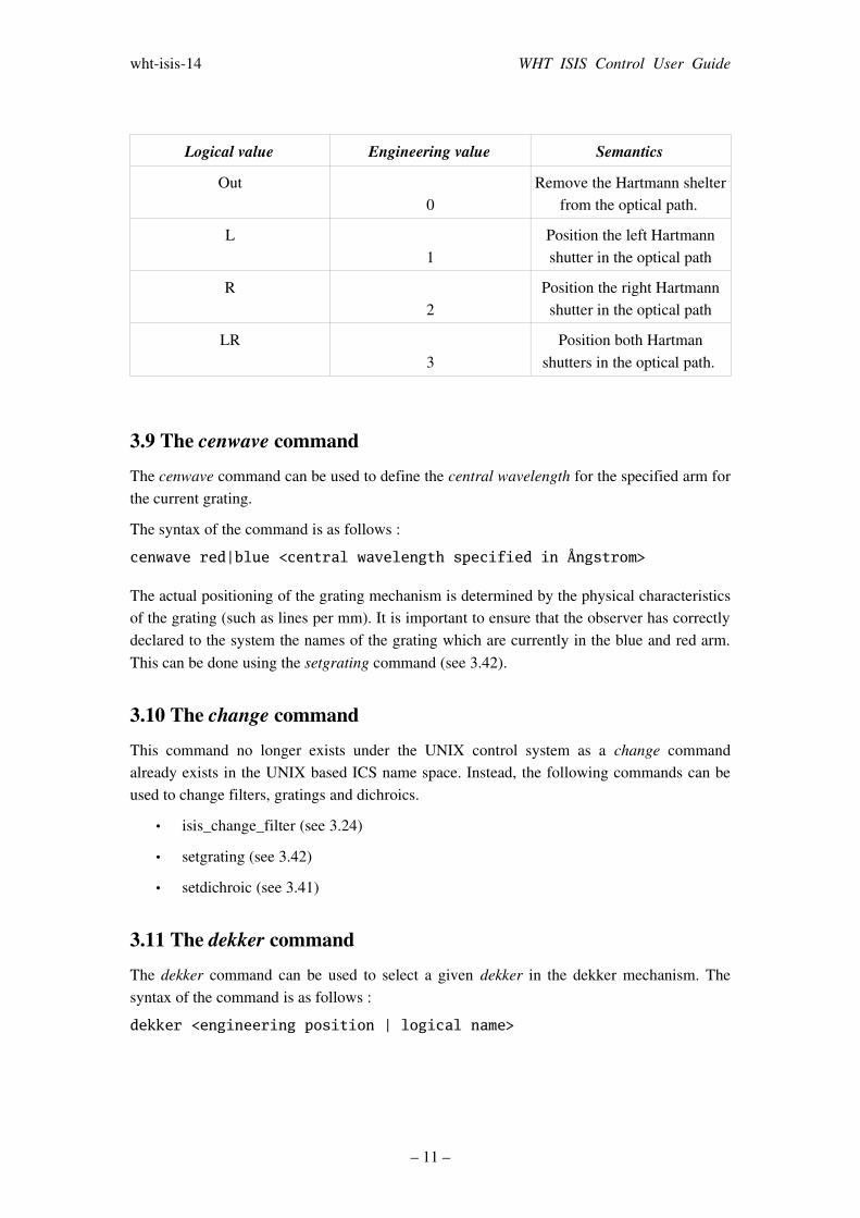
Logical value Engineering value Semantics
Out0
Remove the Hartmann shelter from the optical path.
L1
Position the left Hartmann shutter in the optical path
R2
Position the right Hartmann shutter in the optical path
LR3
Position both Hartman shutters in the optical path.
3.9 The cenwave commandThe cenwave command can be used to define the central wavelength for the specified arm for the current grating.
The syntax of the command is as follows :
cenwave red|blue <central wavelength specified in Ångstrom>
The actual positioning of the grating mechanism is determined by the physical characteristics of the grating (such as lines per mm). It is important to ensure that the observer has correctly declared to the system the names of the grating which are currently in the blue and red arm. This can be done using the setgrating command (see 3.42).
3.10 The change commandThis command no longer exists under the UNIX control system as a change command already exists in the UNIX based ICS name space. Instead, the following commands can be used to change filters, gratings and dichroics.
• isis_change_filter (see 3.24)
• setgrating (see 3.42)
• setdichroic (see 3.41)
3.11 The dekker command The dekker command can be used to select a given dekker in the dekker mechanism. The syntax of the command is as follows :
dekker <engineering position | logical name>
– 11 –
whtisis14 WHT ISIS Control User Guide
The dekker selected can be specified in engineering units in the range of 0..9 or by using one of the following logical values :
• Out
• 20arcsec
• 1.2arcsec
• twin
• barred
• 0.3arcsec
• clear6
• clear7
• clear8
3.12 The imageslicer commandThe imageslicer command can be used to position the image slicer which is located in the slit unit mechanism into the light path.
3.13 The inbcoll command The inbcoll command can be used to initialise the blue collimator mechanism.
3.14 The inbfold command The inbfold command can be used to initialise the blue fold mechanism.
3.15 The inbg command The inbg command can be used to initialise the blue grating mechanism.
3.16 The indek command The indek command can be used to initialise the dekker mechanism.
3.17 The infcp commandThe infcp command can be used to initialise the field calcite polarisation tray mechanism.
3.18 The inrcoll commandThe inrcoll command can be used to initialise the red collimator mechanism.
– 12 –
whtisis14 WHT ISIS Control User Guide
3.19 The inrfold commandThe inrfold command can be used to initialise the red fold mechanism.
3.20 The inrg command The inrg command can be used to initialise the red grating mechanism.
3.21 The inslit command The inslit command can be used to initialise the slit mechanism.
3.22 The isis command This command can be used to start or stop all of the ISIS related software which is required to perform control of the ISIS and A&G instrumentation for observation purposes.
The syntax of the command is as follows :
isis start|stop
3.23 The isis_begin command This command will be executed after the ISIS control system is started. It ensures that the mechanism status for the ISIS instrumentation is uptodate in the instrument control system. Normally this command is executed automatically when the ISIS control system is started. It also ensures that monitor mode has been enabled so that status from the 4MS instrument controller is continously fed to the instrument control system.
3.24 The isis_change_filter commandThe isis_change_filter command is a replacement for the change command which was present upon the VAX control system. The name of the command has been changed because of a namespace clash within the UNIX instrument control system.
After executing the command, the slit door will be unlocked and the dekker mechanism will be positioned in the out position so as to facilitate access to the filter mechanisms for the Observer or engineer.
After the engineer/observer has changed the filter, the command will then lock the slit door mechanism and reposition the dekker mechanism back to its original position.
3.25 The isis_config command The isis_config command can be used to conveniently set up the configuration of the ISIS instrument. It allows the observer to quickly specify the configurations of the red and blue fold mechanisms.
– 13 –
whtisis14 WHT ISIS Control User Guide
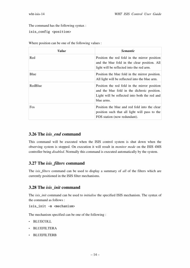
The command has the following syntax :
isis_config <position>
Where position can be one of the following values :
Value Semantic
Red Position the red fold in the mirror position and the blue fold in the clear position. All light will be reflected into the red arm.
Blue Position the blue fold in the mirror position. All light will be reflected into the blue arm.
RedBlue Position the red fold in the mirror position and the blue fold in the dichroic position. Light will be reflected into both the red and blue arms.
Fos Position the blue and red fold into the clear position such that all light will pass to the FOS station (now redundant).
3.26 The isis_end command This command will be executed when the ISIS control system is shut down when the observing system is stopped. On execution it will result in monitor mode on the ISIS 4MS controller being disabled. Normally this command is executed automatically by the system.
3.27 The isis_filters command The isis_filters command can be used to display a summary of all of the filters which are currently positioned in the ISIS filter mechanisms.
3.28 The isis_init command The isis_init command can be used to initialise the specified ISIS mechanism. The syntax of the command as follows :
isis_init -m <mechanism>
The mechanism specified can be one of the following :
• BLUECOLL
• BLUEFILTERA
• BLUEFILTERB
– 14 –

whtisis14 WHT ISIS Control User Guide
• BLUEFOLD
• BLUEGRATING
• FCPTRAY
• REDCOLL
• REDFILTERA
• REDFILTERB
• REDFOLD
• REDGRATING
• SLITUNIT
3.29 The isis_move command This command can be used to position the specified mechanism to the demanded position. The syntax of the command is as follows :
isis_move – m <mechanism> <position>
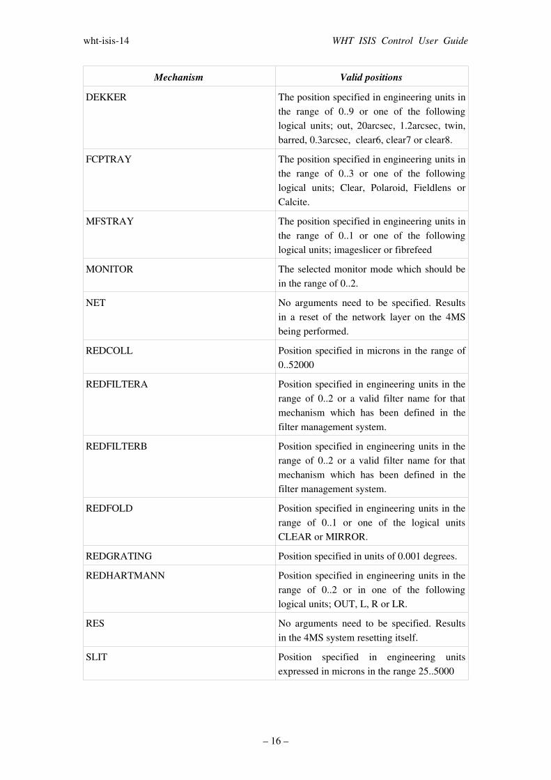
The following table details the valid mechanisms and the positions which can be specified for the isis_move command.
Mechanism Valid positions
BLUECOLL Position specified in microns in the range of 0..52000
BLUEFILTERA Position specified in engineering units in the range of 0..2 or a valid filter name for that mechanism which has been defined in the filter management system (see [WHTFILTDB2])
BLUEFILTERB Position specified in engineering units in the range of 0..2 or a valid filter name for that mechanism which has been defined in the filter management system.
BLUEFOLD Position specified in engineering units in the range of 0..2 or one of the logical units; CLEAR, MIRROR or DICHROIC.
BLUEGRATING Position specified in units of 0.001 degrees.
BLUEHARTMANN Position specified in engineering units in the range of 0..2 or in one of the following logical units; OUT, L, R or LR.
– 15 –
whtisis14 WHT ISIS Control User Guide
Mechanism Valid positions
DEKKER The position specified in engineering units in the range of 0..9 or one of the following logical units; out, 20arcsec, 1.2arcsec, twin, barred, 0.3arcsec, clear6, clear7 or clear8.
FCPTRAY The position specified in engineering units in the range of 0..3 or one of the following logical units; Clear, Polaroid, Fieldlens or Calcite.
MFSTRAY The position specified in engineering units in the range of 0..1 or one of the following logical units; imageslicer or fibrefeed
MONITOR The selected monitor mode which should be in the range of 0..2.
NET No arguments need to be specified. Results in a reset of the network layer on the 4MS being performed.
REDCOLL Position specified in microns in the range of 0..52000
REDFILTERA Position specified in engineering units in the range of 0..2 or a valid filter name for that mechanism which has been defined in the filter management system.
REDFILTERB Position specified in engineering units in the range of 0..2 or a valid filter name for that mechanism which has been defined in the filter management system.
REDFOLD Position specified in engineering units in the range of 0..1 or one of the logical units CLEAR or MIRROR.
REDGRATING Position specified in units of 0.001 degrees.
REDHARTMANN Position specified in engineering units in the range of 0..2 or in one of the following logical units; OUT, L, R or LR.
RES No arguments need to be specified. Results in the 4MS system resetting itself.
SLIT Position specified in engineering units expressed in microns in the range 25..5000
– 16 –
whtisis14 WHT ISIS Control User Guide
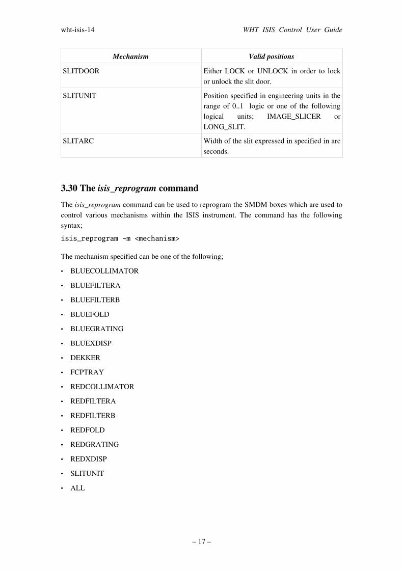
Mechanism Valid positions
SLITDOOR Either LOCK or UNLOCK in order to lock or unlock the slit door.
SLITUNIT Position specified in engineering units in the range of 0..1 logic or one of the following logical units; IMAGE_SLICER or LONG_SLIT.
SLITARC Width of the slit expressed in specified in arc seconds.
3.30 The isis_reprogram commandThe isis_reprogram command can be used to reprogram the SMDM boxes which are used to control various mechanisms within the ISIS instrument. The command has the following syntax;
isis_reprogram -m <mechanism>
The mechanism specified can be one of the following;
• BLUECOLLIMATOR
• BLUEFILTERA
• BLUEFILTERB
• BLUEFOLD
• BLUEGRATING
• BLUEXDISP
• DEKKER
• FCPTRAY
• REDCOLLIMATOR
• REDFILTERA
• REDFILTERB
• REDFOLD
• REDGRATING
• REDXDISP
• SLITUNIT
• ALL
– 17 –

whtisis14 WHT ISIS Control User Guide
Each SMDM module controls up to four mechanisms. When one of the mechanisms associated with a SMDM module is reprogrammed, consequently all of the other mechanisms which are associated with that unit will be reprogrammed automatically. Before these mechanisms can subsequently used, they must all be reinitialised.
This command is only intended to be used by engineers.
3.31 The isis_stop commandThe isis_stop command can be used to stop the movement of a mechanism which is already in motion. The syntax of the command is as follows :
isis_stop -m <mechanism>
The valid mechanisms which can be specified are outlined in the table 3.29
3.32 The isis_update command The isis_update command can be used to request from the ISIS 4MS a status update from the specified mechanism. The syntax of the command is as follows;
isis_update -m <mechanism>
The valid mechanisms which can be specified are outlined in the table 3.29
3.33 The longslit command The longslit command can be used to position the slit unit into the long slit position. This is a replacement for the lslit command which was previously found on the VAX control system but the name of the command had to be changed to do a namespace clash with an existing command in the UNIX ICS.
3.34 The mslit command The mslit command can be used to position the slit unit into the image slicer position.
3.35 The rcoll commandThis command can be used to position the collimator on the red arm. The syntax of the command is as follows;
rcoll <position>
The position should be specified in units of microns and be in the range of 0 to 30000.
– 18 –
whtisis14 WHT ISIS Control User Guide
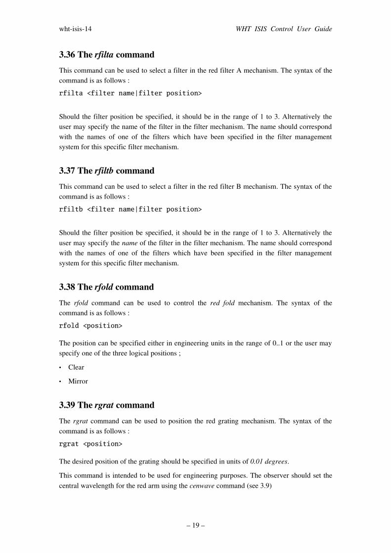
3.36 The rfilta commandThis command can be used to select a filter in the red filter A mechanism. The syntax of the command is as follows :
rfilta <filter name|filter position>
Should the filter position be specified, it should be in the range of 1 to 3. Alternatively the user may specify the name of the filter in the filter mechanism. The name should correspond with the names of one of the filters which have been specified in the filter management system for this specific filter mechanism.
3.37 The rfiltb commandThis command can be used to select a filter in the red filter B mechanism. The syntax of the command is as follows :
rfiltb <filter name|filter position>
Should the filter position be specified, it should be in the range of 1 to 3. Alternatively the user may specify the name of the filter in the filter mechanism. The name should correspond with the names of one of the filters which have been specified in the filter management system for this specific filter mechanism.
3.38 The rfold commandThe rfold command can be used to control the red fold mechanism. The syntax of the command is as follows :
rfold <position>
The position can be specified either in engineering units in the range of 0..1 or the user may specify one of the three logical positions ;
• Clear
• Mirror
3.39 The rgrat commandThe rgrat command can be used to position the red grating mechanism. The syntax of the command is as follows :
rgrat <position>
The desired position of the grating should be specified in units of 0.01 degrees.
This command is intended to be used for engineering purposes. The observer should set the central wavelength for the red arm using the cenwave command (see 3.9)
– 19 –
whtisis14 WHT ISIS Control User Guide
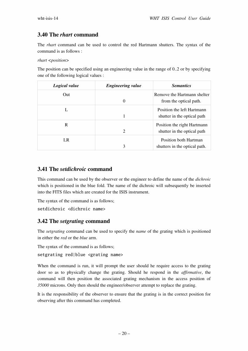
3.40 The rhart commandThe rhart command can be used to control the red Hartmann shutters. The syntax of the command is as follows :
rhart <position>
The position can be specified using an engineering value in the range of 0..2 or by specifying one of the following logical values :
Logical value Engineering value Semantics
Out0
Remove the Hartmann shelter from the optical path.
L1
Position the left Hartmann shutter in the optical path
R2
Position the right Hartmann shutter in the optical path
LR3
Position both Hartman shutters in the optical path.
3.41 The setdichroic command This command can be used by the observer or the engineer to define the name of the dichroic which is positioned in the blue fold. The name of the dichroic will subsequently be inserted into the FITS files which are created for the ISIS instrument.
The syntax of the command is as follows;
setdichroic <dichroic name>
3.42 The setgrating command The setgrating command can be used to specify the name of the grating which is positioned in either the red or the blue arm.
The syntax of the command is as follows;
setgrating red|blue <grating name>
When the command is run, it will prompt the user should he require access to the grating door so as to physically change the grating. Should he respond in the affirmative, the command will then position the associated grating mechanism in the access position of 35000 microns. Only then should the engineer/observer attempt to replace the grating.
It is the responsibility of the observer to ensure that the grating is in the correct position for observing after this command has completed.
– 20 –
whtisis14 WHT ISIS Control User Guide
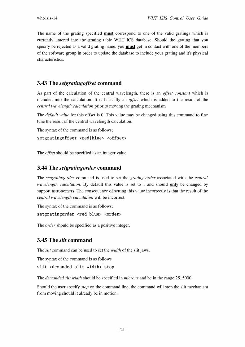
The name of the grating specified must correspond to one of the valid gratings which is currently entered into the grating table WHT ICS database. Should the grating that you specify be rejected as a valid grating name, you must get in contact with one of the members of the software group in order to update the database to include your grating and it's physical characteristics.
3.43 The setgratingoffset command As part of the calculation of the central wavelength, there is an offset constant which is included into the calculation. It is basically an offset which is added to the result of the central wavelength calculation prior to moving the grating mechanism.
The default value for this offset is 0. This value may be changed using this command to fine tune the result of the central wavelength calculation.
The syntax of the command is as follows;
setgratingoffset <red|blue> <offset>
The offset should be specified as an integer value.
3.44 The setgratingorder command The setgratingorder command is used to set the grating order associated with the central wavelength calculation. By default this value is set to 1 and should only be changed by support astronomers. The consequence of setting this value incorrectly is that the result of the central wavelength calculation will be incorrect.
The syntax of the command is as follows;
setgratingorder <red|blue> <order>
The order should be specified as a positive integer.
3.45 The slit command The slit command can be used to set the width of the slit jaws.
The syntax of the command is as follows
slit <demanded slit width>|stop
The demanded slit width should be specified in microns and be in the range 25..5000.
Should the user specify stop on the command line, the command will stop the slit mechanism from moving should it already be in motion.
– 21 –

whtisis14 WHT ISIS Control User Guide
3.46 The slit_door commandThe slit_door command will be used to lock and unlock the slit door to allow access to the inside of the instrument for filter changes etc.
The command takes the following syntax;
slit_door [-h] unlock|lock
3.47 The slitarc command The slitarc command can be used by the Observer to specify the demanded slit width in arc seconds.
The syntax of the command is as follows
slitarc [-h] <demanded slit width in arc seconds>
– 22 –
whtisis14 WHT ISIS Control User Guide
Chapter 4 ISIS and A&G GUI Control ApplicationIn addition to being able to be controlled through the WHT ICS console command line, the ISIS and A&G instrument (see [WHTCAGB6]) may also be controlled by means of a graphical user interface (GUI).
The following sections detail the GUI control application which can be used in order to do this.
4.1 Starting the GUI Normally, as part of the startup sequence of the observing system, the control GUI for the ISIS instrument will be started automatically providing that the ISIS has been configured into the observing system by the engineers.
Should the user need to start the application manually, this can be done using the following command from the WHT OCS console command line after the observing system has been started.
4MSControl -panels “IS IS CAGB” &
4.2 Colour CodingWhen a status value associated with a mechanism is in an error state, the text associated with the status item will be highlighted in red.
When a mechanism is moving, the control associated with that mechanism will be insensitive to user interaction and any text associated with it will be coloured blue.
Should there be an outstanding warning associated with a mechanism, any status text field associated with that mechanism will be highlighted with a yellow background.
4.3 IconsA number of icons buttons are used throughout the GUI in order to perform specific tasks. Care has been exercised to ensure that the meanings of each of the icons is consistent across not just the control panels which are used to operate the ISIS instrument, but also the rest of the other instruments which are controlled by the same application.
A summary of the icons which are used within the application follows.
Icon Semantics
This icon signifies that when this button is pressed, the associated mechanism will be initialised.
This icon signifies that when this button is pressed, the associated mechanism will move
– 23 –
whtisis14 WHT ISIS Control User Guide
Icon Semantics
to the demanded position.
This icon signifies that when this button is pressed, the displayed position of the associated mechanism will be updated to that of the current mechanism position and as such, will override any demand position which may have been entered by the user.
This icon signifies that when this button is pressed, the associated mechanism will be stopped should it be moving.
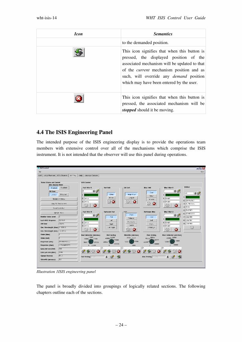
4.4 The ISIS Engineering PanelThe intended purpose of the ISIS engineering display is to provide the operations team members with extensive control over all of the mechanisms which comprise the ISIS instrument. It is not intended that the observer will use this panel during operations.
The panel is broadly divided into groupings of logically related sections. The following chapters outline each of the sections.
– 24 –
Illustration 1ISIS engineering panel
whtisis14 WHT ISIS Control User Guide
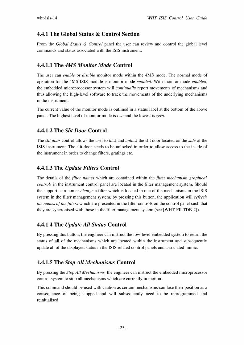
4.4.1 The Global Status & Control SectionFrom the Global Status & Control panel the user can review and control the global level commands and status associated with the ISIS instrument.
4.4.1.1 The 4MS Monitor Mode ControlThe user can enable or disable monitor mode within the 4MS mode. The normal mode of operation for the 4MS ISIS module is monitor mode enabled. With monitor mode enabled, the embedded microprocessor system will continually report movements of mechanisms and thus allowing the highlevel software to track the movements of the underlying mechanisms in the instrument.
The current value of the monitor mode is outlined in a status label at the bottom of the above panel. The highest level of monitor mode is two and the lowest is zero.
4.4.1.2 The Slit Door ControlThe slit door control allows the user to lock and unlock the slit door located on the side of the ISIS instrument. The slit door needs to be unlocked in order to allow access to the inside of the instrument in order to change filters, gratings etc.
4.4.1.3 The Update Filters ControlThe details of the filter names which are contained within the filter mechanism graphical controls in the instrument control panel are located in the filter management system. Should the support astronomer change a filter which is located in one of the mechanisms in the ISIS system in the filter management system, by pressing this button, the application will refresh the names of the filters which are presented in the filter controls on the control panel such that they are syncronised with those in the filter management system (see [WHTFILTDB2]).
4.4.1.4 The Update All Status Control By pressing this button, the engineer can instruct the lowlevel embedded system to return the status of all of the mechanisms which are located within the instrument and subsequently update all of the displayed status in the ISIS related control panels and associated mimic.
4.4.1.5 The Stop All Mechanisms ControlBy pressing the Stop All Mechanisms, the engineer can instruct the embedded microprocessor control system to stop all mechanisms which are currently in motion.
This command should be used with caution as certain mechanisms can lose their position as a consequence of being stopped and will subsequently need to be reprogrammed and reinitialised.
– 25 –
whtisis14 WHT ISIS Control User Guide
4.4.1.6 The Reset Controller ControlBy pressing this button the engineer can instruct the 4MS embedded microprocessor control system to reset itself.
4.4.1.7 The Last 4MS Response Status LabelThe ISIS software instrument controller system attempts to handshake with the 4MS embedded microprocessor system every 5 minutes. In the status field labelled Last 4MS Response is the time of the last successful handshake between the software controller and the instrument.
4.4.2 The ISIS Control PanelFrom the panel below, the observer or engineer will be able to control and review status for mechanisms which comprise the ISIS spectrograph.
– 26 –
Illustration 2Global Status and Control Panel
whtisis14 WHT ISIS Control User Guide
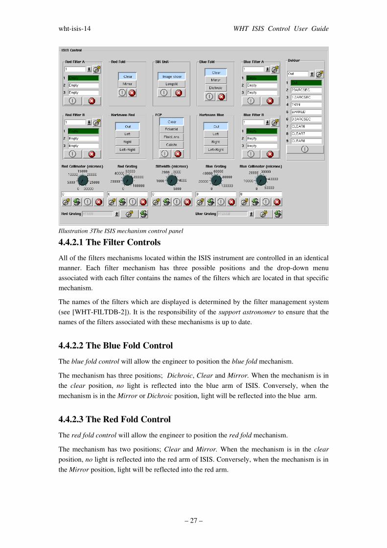
4.4.2.1 The Filter ControlsAll of the filters mechanisms located within the ISIS instrument are controlled in an identical manner. Each filter mechanism has three possible positions and the dropdown menu associated with each filter contains the names of the filters which are located in that specific mechanism.
The names of the filters which are displayed is determined by the filter management system (see [WHTFILTDB2]). It is the responsibility of the support astronomer to ensure that the names of the filters associated with these mechanisms is up to date.
4.4.2.2 The Blue Fold ControlThe blue fold control will allow the engineer to position the blue fold mechanism.
The mechanism has three positions; Dichroic, Clear and Mirror. When the mechanism is in the clear position, no light is reflected into the blue arm of ISIS. Conversely, when the mechanism is in the Mirror or Dichroic position, light will be reflected into the blue arm.
4.4.2.3 The Red Fold ControlThe red fold control will allow the engineer to position the red fold mechanism.
The mechanism has two positions; Clear and Mirror. When the mechanism is in the clear position, no light is reflected into the red arm of ISIS. Conversely, when the mechanism is in the Mirror position, light will be reflected into the red arm.
– 27 –
Illustration 3The ISIS mechanism control panel
whtisis14 WHT ISIS Control User Guide
Note that in order to ensure that light reaches the red arm, it is also important to position the blue fold mechanism (see 4.4.2.2) into the dichroic or clear position also.
4.4.2.4 The Hartmann Shutter ControlsThe Hartmann shutters which are associated with the red and the blue arms are controlled in an identical manner. The user may select either the left or right shutter or both of them by clicking on one of the buttons in the control and acknowledging the confirmation dialog that will subsequently be displayed.
It is important that prior to science operations, the observer or the engineer removes the Hartmann shutters from the optical path otherwise the amount of light reaching the science detectors will be reduced considerably.
The mimic which is associated with the ISIS instrument highlights the fact that the Hartmann shutters are in the optical path by outlining the light which is going into the science detectors in red.
4.4.2.5 The Slit Unit ControlThe slit unit control allows the observer to position the slit unit in one of the two following positions; long slit or image slicer.
In order to select a new position, the Observer needs to simply click the button which is labelled with the desired position and then acknowledge the confirmation dialog which is subsequently displayed.
4.4.2.6 The FCP Tray ControlThe FCP control allows the observer to control the position of the field calcite polarisation tray . The tray has four possible positions; out, polaroid, calcite and fieldlens.
In order to change the position of the mechanism the user should press on the button which is labelled with the desired position and then acknowledge the confirmation dialog which is subsequently displayed.
4.4.2.7 The Collimator Position ControlsThe red and blue collimator controls are used to position the collimator mechanisms. Each of the controls behaves in exactly the same manner. The engineer can change the demand position of the collimator by either rotating the associated dial or entering the new position in the text field which is associated with the control.
The range of movement of the red collimator is 030000 microns and that of the blue collimator is 050000 microns.
– 28 –

whtisis14 WHT ISIS Control User Guide
4.4.2.8 The Grating Position ControlsThe red and blue grating controls are used to position the gratings which are located in the red and blue arms. Each of the controls behaves in exactly the same manner. The engineer can change the demand position of the grating by either rotating the associated dial or entering the new position in the text field which is associated with the control.
The range of movement of the red grating is 0100000 and that of the blue grating is 050000. The units of movement are expressed in 0.001 degrees.
In order to position the gratings for science operations, the Observer should use either the cenwave command line script (see 3.9) or use the cenwave controls on the ISIS observer control panel (see 4.5).
4.4.2.9 The Slitwidth ControlThe slit width control can be used by the engineer to adjust the width of the slit. The demand position for the width can be specified in microns and can be changed by rotating the control dial or by modifying the position in the text field which is associated with the control.
The range of movement for the slit width is 55000 microns.
4.4.2.10 The Dekker ControlThe dekker control will allow the engineer to select a different dekker in the dekker tray. To change the position of the mechanism, the user needs to select the demanded dekker position from the dropdown menu associated with the control and then press the move button.
4.4.2.11 The Grating Specifier ControlsLocated at the foot of the panel are two controls which allow the observer to specify the names of the gratings which are associated with the red and blue arm. It is imperative that the correct gratings are specified otherwise the central wavelength calculation will not function correctly.
When the name of a grating is changed, the ISIS instrument control system will recalculate the position of the grating on the associated arm in accordance with it's physical characteristics so as the central wavelength for that arm is preserved.
The names of the gratings which can be selected are stored in the WHT ICS database and should the grating you require not be present in this list, you will need to contact a member of the software group in order to update the list of gratings.
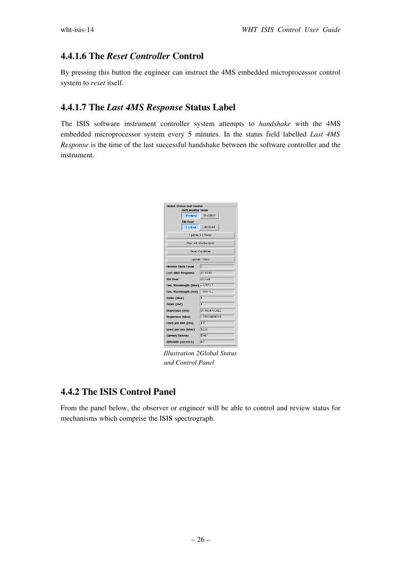
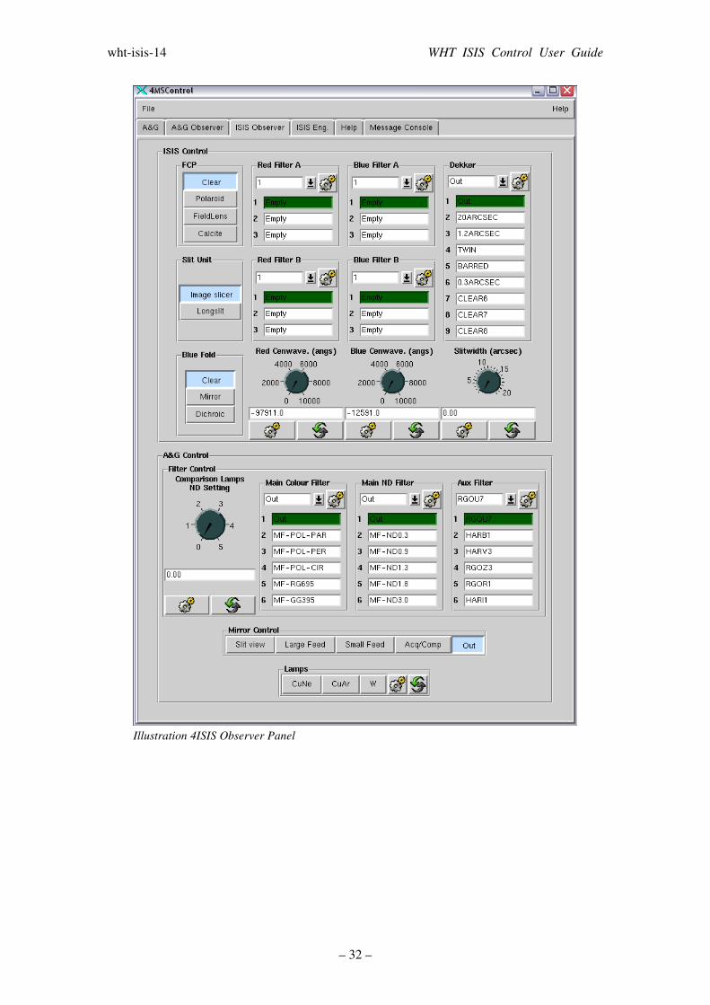
4.5 The ISIS Observer Control PanelThe intended purpose of this panel is to provide the Observer with all of the controls which he will need to coordinate both the ISIS and A&G instrumentation during nighttime science
– 29 –

whtisis14 WHT ISIS Control User Guide
operations. This control panel contains a subset of the mechanism controls which are to be found on the engineering panels of both the ISIS and A&G instruments.
For more information relating to the control of the A&G instrument refer to [WHTCAGB6].
The following sections outline the controls which are to be found on this panel.
4.5.1 ISIS Related controlsInformation relating to the operation of the majority of the ISIS specific controls in the observer panel can be found in the previous sections as they behave identically to those in the engineering panel.
4.5.1.1 The slitwidth Control The slitwidth control will permit the Observer to specify the width of the slit expressed in arc seconds. The user can define the demanded slit width using the dial associated with the control and, by pressing the move button, can instruct the instrument control task to set the slit width accordingly.
4.5.1.2 The cenwave ControlsThe red and blue cenwave controls can be used to define a central wavelength specified in Ångstroms for the blue and the red gratings. The user can define the demanded wavelength using dials associated with the controls and by pressing the move button, can instruct the instrument control task to calculate the position of the grating.
In order to perform this calculation correctly, it is important that the Observer has previously defined the gratings which are currently located in the red and the blue arm (see 3.42).
4.5.2 The A&G Mechanism ControlsThe ISIS spectrograph is used in conjunction with the Cassegrain Acquisition and Guidance system (A&G). It is therefore logical that the observer should be able to control both instruments from the same panel.
The following sections outline the controls upon the ISIS observer panel which are related to the A&G box (see [WHTCAGB6]).
4.5.2.1 The Comparison Lamps ND Setting Control This control allows the user to specify a demand neutral density setting between zero and five. The user may specify the demand value either by turning the associated dial control or by entering the neutral density setting manually through the text field.
– 30 –
whtisis14 WHT ISIS Control User Guide
To affect the new neutral density setting, the user should press the move icon. The instrument controller will then attempt to select neutral density filters in the comparison system neutral density filter mechanisms such that the combined effect of both of the filters amounts to as close as possible, the neutral density setting demanded by the user.
4.5.2.2 The AUX Filter ControlThis AUX Filter control allows the user to select which filter is currently selected in the auxiliary filter mechanism. The user should select the demanded filter from the dropdown menu and then press the move icon to effect the move.
4.5.2.3 The Main Colour Filter ControlThis main colour filter control allows the user to select which filter is currently selected in the main colour filter mechanism. The user should select the demanded filter from the dropdown menu and then press the move icon to effect the move.
4.5.2.4 The Main ND Filter ControlThis main neutral density filter control allows the user to select which filter is currently selected in the main neutral density filter mechanism. The user should select the demanded filter from the dropdown menu and then press the move icon to effect the move.
4.5.2.5 The Lamps ControlThe lamps control allows the user to illuminate any combination of the three currently available lamps in the calibration system. The user can select the lamps that he wants illuminating by depressing the button with the corresponding lamp name. In order to effect the change, the user should press the move icon.
Due to a hardware problem in the lowlevel embedded microprocessor system, sometimes it will be necessary to repeat this process up to two or three times before the lamps will be illuminated.
4.5.2.6 The Mirror ControlUsing the mirror control, the observer can specify which of the mirrors in the A&G system is to be positioned in the optical path. In order to position a mirror into the path of the beam, the user should press the button which is labelled with the desired mirror name. A confirmation window will be presented to the user prior to moving the mirror to ensure that this was the intention.
– 31 –
whtisis14 WHT ISIS Control User Guide
– 32 –
Illustration 4ISIS Observer Panel

whtisis14 WHT ISIS Control User Guide
BibliographyWHTCAGB6: Craige Bevil, WHT A&G System User Guide, 2005WHTFILTDB2: Craige Bevil, User Guide to the Filter Management System, 2004
– 33 –