wing loads calculation
TRANSCRIPT
WING LOAD CALCULATIONCompany
logo
Document reference:
Page 1of 33
Date Revision company name
Doc.-No.
WING LOAD CALCULATION(Example document for LSA applicants – v1 of 08.03.16)
Approval data
Prepared by Verified by Approved by
Name, sign.
Function Design Engineer Design Manager
Record of Revision
Rev. # Issue date Description of change
0 Initial issue
Date of issue: DD/MM/YYYY
Document reference: ABCD-FL-57-00
company name
WING LOAD CALCULATIONCompany
logo
Document reference:
Page 2of 33
DateRevisionDoc.-No.
0. Introduction
This document calculates the flight loads on the wings of the ABCD aircraft. The requirements are referenced in the compliance checklist of the certification programme ABCD-CP-00.
Within this document the loads on the wings are determined throughout the whole flight envelope [1] and for the design weights as determined in [2] under all loading conditions.
The simplified criteria of requirement X.1 [3] have not been used for these calculations.
The Loads are calculated using literature methods taken from the documents referenced in chapter 1.
The following assumptions are made:
Applicable to LSA only; no compressibility effects; conventional configuration (e.g. no tandem aircraft, bi-plane or canard); no pitching moment of the horizontal tail (symmetrical profile); no winglets, no wing tip tanks; no sweep, straight leading edge, no twist, constant profile, no dihedral; effect of the wing deformation on the loads not considered; no spoilers or airbrakes; landing gear attached to fuselage; no wing struts (cantilever wing);
NOTICEThis document is to provide an example of a flight load calculation document for an aircraft type certificate application in accordance with CS-LSA. The document can be used even if the applicant does not own a DOA. It does not substitute, in any of its parts, the prescriptions of Part-21 and its amendments.
This document is intended to assist applicants in applying for an LSA RTC/TC and therefore demonstrating compliance of the design to the requirements.
The document should not be read as a template and it should not be used as a form to fill. The content shall be checked for appropriateness and changed accordingly by the applicant.
The required information can be presented entirely in this document, or in additional documents appropriately identified and referred to.
Comments and notes to the user are provided throughout the document with “blue highlighted and italic text”.
IMPORTANT: All the statements and/or conclusions provided in this guideline can be considered realistic and have a reasonable technical basis but the designer is solely responsible of each of the statements that he/she will provide

WING LOAD CALCULATIONCompany
logo
Document reference:
Page 3of 33
Date Revision company name
Doc.-No.
Contents
0. Introduction 2
1. References 4
2. List of Abbreviations 4
3. Requirements 6
4. Input data 8
5. Load Calculation 9
6. Load cases 9
6.1. Loads on the aeroplane 13
6.1.1. Reference axes and sign convention 13
6.1.2. Symmetrical flight conditions 13
6.1.3. Aerodynamic centre 15
6.1.4. Pitching moment of the wing 15
6.1.5. Influence of the fuselage 16
6.2. Forces and moments acting on the wings 16
6.3. Unsymmetrical flight conditions 18
6.4. Wing load distribution 19
6.4.1. Wing lift distribution 19
6.4.2. Wing drag distribution 21
6.4.3. Wing and fuel mass distribution 21
6.4.4. Wing torsion distribution 22
6.4.5. Distribution of internal loads 23
7. Compliance statements 31

company name
WING LOAD CALCULATIONCompany
logo
Document reference:
Page 4of 33
DateRevisionDoc.-No.
1. References
[1] “ABCD-FE-01-00 Flight Envelope,” EASA.[2] “ABCD-WB-08-00 Weight and Balance Report,” EASA.[3] “ASTM F2245-12d,” ASTM.[4] “CS-LSA Certification Specificatoions and Acceptable Means of Compliance, Amnd.1 29.Jul.2013,” EASA,
2013.[5] “Report 751 - The Mean Aerodynamic Chord and the Aerodynamic Center of a Tapered Wing,” NACA, 1942.[6] “ABCD-GD-01-00 Aeroplane General Description,” EASA.[7] “NACA Report No.824, Summary of Airfoil Data,” NACA, 1945.[8] “USAF Stability and Control DATCOM,” MacDonell Douglas Corporation, April 1983.[9] “Royal Aeronautical Society Data Sheet Aircraft 08.01.01,” Royal Aeronautical Society.
[10] Schrenk, “Technical Memorandum 948 - A SIMPLE APPROXIMATION METHOD FOR OBTAINING THE SPANWISE LIFT DISTRIBUTION,” NACA, 1940.
[11] L. R. B. Etkin, Dynamics of Flight - Stability and Control third edition, J. Wiley & sons, 1996.
2. List of Abbreviations
CG centre of gravityLE leading edgeISA international standard atmosphere by International Organisation for Standardisation KEAS knots equivalent airspeedMAC mean aerodynamic chordMTOW maximum take-off weightSI international system of units
α angle of attack of the wing [deg]α i local angle of attack of the station i [deg]α cL=0 wing zero lift angle of attack [deg]α cL=0airfoil profile zero lift angle of attack [deg]a lift curve slope
[1/deg]
AR wing aspect ratio calculated by AR=b2
S[]
b wing span [m]b i average wing span at station i (mid span position of station) [m]bMAC wing span position of MAC [m]b0 average fuselage width at wing section [m]b fuse maximum fuselage width (equals b0) [m]β i local angle between resulting force and normal force at station [deg]c i average chord at station i [m]cMAC mean aerodynamic chord [m]croot chord at wing root [m]c tip chord at wing tip [m]cshear shear axis relative position as a fraction of local wing chord []cD drag coefficient []c L lift coefficient []cmfuse
fuselage pitching moment coefficient []cm0 zero lift profile pitching moment coefficient []

WING LOAD CALCULATIONCompany
logo
Document reference:
Page 5of 33
Date Revision company name
Doc.-No.
cm0w zero lift wing pitching moment coefficient []D drag force on the wings [N]d span wise drag line loading []φc/4 wing sweep of the quarter chord line [deg] g gravity acceleration [m/s2]K f fuselage moment factor []L total wing lift force (on both wings) [N]Li local lift at station i [N]li lift line loading on the wing [N/m]LHT total horizontal tail lift force [N]lfuse total fuselage length [m]lN fuselage length in front of wing quarter mean aerodynamic chord point [m]
λ taper ratio (equals crootc tip
) []
M AC wing pitching moment with lift acting on its aerodynamic centre [N]M Y moments around y axis [Nm]N normal force [N]n load factor []num total number of stations of a single wing; num = 10 []
ρ density of ambient air at a specific altitude [kgm3
]
QDirunning horizontal shear force at station i (direction parallel to drag force) [N]
∆QDiincremental horizontal shear force at station i (direction parallel to drag force) [N]
QLi running vertical shear force at station I (direction parallel to lift force) [N]∆QLi incremental vertical shear force at station i (direction parallel to lift force) [N]Ri local resulting force at station i [N]S wing area (not including wing carry-through) [m2]T i local tangential force at station i [N]T S total torsion around elastic axis of the wing (at wing root) [mN]T Si local torsion around elastic axis of the wing at station i [mN]∆T Si incremental torsion around elastic axis of the wing at station i [mN]
μ dynamic viscosity (for Reynolds number) [N sm2 ]
v airspeed [m/s]W total aircraft weight [kg]mfuel i local weight of the wing at station i (with no fuel or payload) [kg/m2]mwing total weight of a single wing (with no fuel or payload) [kg]mwingi local weight of the wing at station i (with no fuel or payload) [kg/m2]x longitudinal axis of the aircraft [m]xHT
distance to HT quarter chord line from wing LE (at mean aerodynamic chord) [m]xCG distance to aircraft centre of gravity from wing LE (at mean aerodynamic chord) [m]xCG f
distance to fuel centre of gravity from wing LE (at mean aerodynamic chord) [m]xCGw
distance to wing centre of gravity from wing LE (at mean aerodynamic chord) [m]xCG¿
local distance to wing centre of gravity from wing LE at station i [m]∆ x N fuse aerodynamic centre shift due to fuselage pitching moment [m]x AC aerodynamic centre of the wing with respect to wing LE

company name
WING LOAD CALCULATIONCompany
logo
Document reference:
Page 6of 33
DateRevisionDoc.-No.
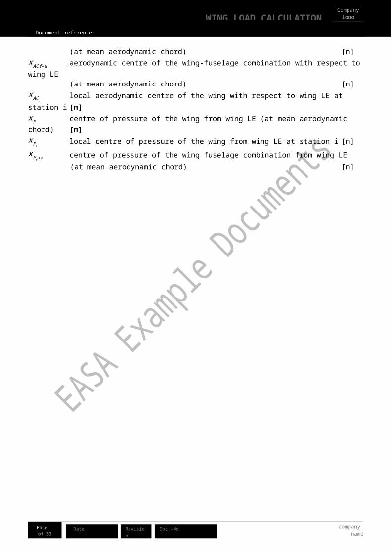
(at mean aerodynamic chord) [m]x ACf +w aerodynamic centre of the wing-fuselage combination with respect to wing LE (at mean aerodynamic chord) [m]x AC i
local aerodynamic centre of the wing with respect to wing LE at station i [m]xP centre of pressure of the wing from wing LE (at mean aerodynamic chord) [m]xPi
local centre of pressure of the wing from wing LE at station i [m]xP f+w centre of pressure of the wing fuselage combination from wing LE
(at mean aerodynamic chord) [m]

WING LOAD CALCULATIONCompany
logo
Document reference:
Page 7of 33
Date Revision company name
Doc.-No.
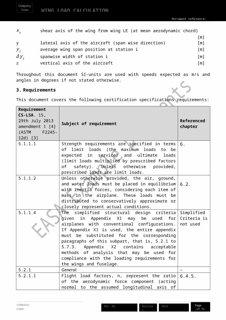
xs shear axis of the wing from wing LE (at mean aerodynamic chord) [m]y lateral axis of the aircraft (span wise direction) [m]y i average wing span position at station i [m]∆ y i spanwise width of station i [m]z vertical axis of the aircraft [m]
Throughout this document SI-units are used with speeds expected as m/s and angles in degrees if not stated otherwise.
3. Requirements
This document covers the following certification specifications requirements:
RequirementCS-LSA. 15, 29th July 2013 amendment 1 [4](ASTM F2245-12d) [3]
Subject of requirement Referenced chapter
5.1.1.1 Strength requirements are specified in terms of limit loads (the maximum loads to be expected in service) and ultimate loads (limit loads multiplied by prescribed factors of safety). Unless otherwise provided, prescribed loads are limit loads.
6
5.1.1.2 Unless otherwise provided, the air, ground, and water loads must be placed in equilibrium with inertia forces, considering each item of mass in the airplane. These loads must be distributed to conservatively approximate or closely represent actual conditions.
6.2
5.1.1.4 The simplified structural design criteria given in Appendix X1 may be used for airplanes with conventional configurations. If Appendix X1 is used, the entire appendix must be substituted for the corresponding paragraphs of this subpart, that is, 5.2.1 to 5.7.3. Appendix X2 contains acceptable methods of analysis that may be used for compliance with the loading requirements for the wings and fuselage.
Simplified Criteria is not used
5.2.1 General: –5.2.1.1 Flight load factors, n, represent the ratio of the aerodynamic force
component (acting normal to the assumed longitudinal axis of the airplane) to the weight of the airplane. A positive flight load factor is one in which the aerodynamic force acts upward, with respect to the airplane.
6.4.5
5.2.1.2 Compliance with the flight load requirements of this section must be shown at each practicable combination of weight and disposable load within the operating limitations specified in the POH.
6
5.2.2 Symmetrical Flight Conditions: - 5.2.2.1 The appropriate balancing horizontal tail loads must be accounted
for in a rational or conservative manner when determining the wing loads and linear inertia loads corresponding to any of the symmetrical flight conditions specified in 5.2.2 to 5.2.6.
6.1
5.2.2.2 The incremental horizontal tail loads due to maneuvering and gusts must be reacted by the angular inertia of the airplane in a rational or conservative manner.
Insignificant to wing loads
5.2.2.3 In computing the loads arising in the conditions prescribed above, 6.1

company name
WING LOAD CALCULATIONCompany
logo
Document reference:
Page 8of 33
DateRevisionDoc.-No.
RequirementCS-LSA. 15, 29th July 2013 amendment 1 [4](ASTM F2245-12d) [3]
Subject of requirement Referenced chapter
the angle of attack is assumed to be changed suddenly without loss of air speed until the prescribed load factor is attained. Angular accelerations may be disregarded.
5.2.2.4 The aerodynamic data required for establishing the loading conditions must be verified by tests, calculations, or by conservative estimation. In the absence of better information, the maximum negative lift coefficient for rigid lifting surfaces may be assumed to be equal to −0.80. If the pitching moment coefficient, Cmo, is less than ±0.025, a coefficient of at least ±0.025 must be used.
6.16.2
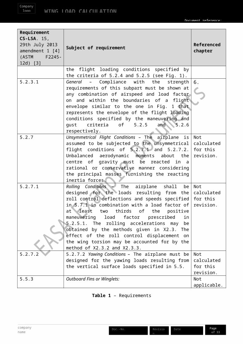
5.2.3 Flight Envelope – Compliance shall be shown at any combination of airspeed and load factor on the boundaries of the flight envelope. The flight envelope represents the envelope of the flight loading conditions specified by the criteria of 5.2.4 and 5.2.5 (see Fig. 1).
6
5.2.3.1 General – Compliance with the strength requirements of this subpart must be shown at any combination of airspeed and load factor on and within the boundaries of a flight envelope similar to the one in Fig. 1 that represents the envelope of the flight loading conditions specified by the maneuvering and gust criteria of 5.2.5 and 5.2.6 respectively.
6
5.2.7 Unsymmetrical Flight Conditions – The airplane is assumed to be subjected to the unsymmetrical flight conditions of 5.2.7.1 and 5.2.7.2. Unbalanced aerodynamic moments about the centre of gravity must be reacted in a rational or conservative manner considering the principal masses furnishing the reacting inertia forces.
Not calculated for this revision.
5.2.7.1 Rolling Conditions – The airplane shall be designed for the loads resulting from the roll control deflections and speeds specified in 5.7.1 in combination with a load factor of at least two thirds of the positive maneuvering load factor prescribed in 5.2.5.1. The rolling accelerations may be obtained by the methods given in X2.3. The effect of the roll control displacement on the wing torsion may be accounted for by the method of X2.3.2 and X2.3.3.
Not calculated for this revision.
5.2.7.2 5.2.7.2 Yawing Conditions – The airplane must be designed for the yawing loads resulting from the vertical surface loads specified in 5.5.
Not calculated for this revision.
5.5.3 Outboard Fins or Winglets: Not applicable.
Table 1 – Requirements
WING LOAD CALCULATIONCompany
logo
Document reference:
Page 9of 33
Date Revision company name
Doc.-No.
4. Input data
The values shown below are derived from design data or other compliance documents for this particular aeroplane.
aircraft design dataabbreviation Units Value source Comment
mean aerodynamic chord length c_MAC m 1.4 design description empty weight W_empty kg 380 design description empty CG x_W_E m 0.4033 measured at c_MAC
max fwd CG x_W_fwd m 0.25 (FTP document) at c_MAC
max aft CG X_W_aft m 0.39 (FTP document) at c_MAC
weight unusable fuel w_Fuelunusable kg 6 measuredmax fuel w_fuelMax kg 80 measuredfuel centre of gravity X_CG_f m 0.3 design data at c_MAC
max weight W kg 600 cert. basis pax lever arm x_pax m 0 design data at c_MAC
max pax load kg 214 design data fuel tank span b_wingfuel_2 m 2 design data across 2 stationsbaggage compartment lever arm x_bag m 0.6 design data at c_MAC
max baggage compartment load W_bag_max kg 20 design description shear centre of wing (elastic axis) x_s m 0.42 design data at c_MAC
CG of wing x_CGw m 0.63 design data at c_MAC
wing weight m_wing kg 50 design data wing span b m 10.78 design description horizontal tail MAC c_HT m 0.75 design data horizontal tail area S_HT m^2 2.0 design data horiz tail span b_HT m 2.65 design data CHT/4 horizTail lever arm x_HT m 3 design datawing thickness at spar y_.4/c 0.16 NACA report 824 main spar location x_spar m 0.35 design data
aerodynamic input data abbreviation Units Value source Commentaspect ratio AR 7.70 design data wing area S m2 15.1 design datawetted wing area SW m2 13.6 design datazero lift angle of flap section α_CL=0,flaps deg -15 NACA report 824 Re = 3E6 (p.237)zero lift angle α_CL=0,airfoil deg -2 NACA report 824 Re = 2.9E6 (p.236)chord at wing root c_root m 1.54 design data chord at wing tip c_tip m 1.26 design data wing span in fuselage b_0 = b_fuse m 1 design data wing c/4 to fuselage l_N/l_fuse 0.4 design data fuselage total length l_fuse m 6.5 design data zero lift pitch moment coeff c_m0 -0.055 NACA report 824 Re = 2.9E6 (p.236)
company name
WING LOAD CALCULATIONCompany
logo
Document reference:
Page 10of 33
DateRevisionDoc.-No.
aerodynamic input data abbreviation Units Value source Commentflap zero lift pitch moment coeff c_m0,flap -0.3 NACA report 824 (p.237)
profile NACA 66(215)
-216 NACA report 824data source=polar plot
max lift w/o flaps c_L_max 1.35 NACA report 824Re = 2.9E6 (p.236), using 18% reserve
max lift full flaps (flapped area) c_L_flapsmax 2.15 NACA report 824
(p.237), using 18% reserve at 40 degrees deflection
other input data abbreviation Units Value source Commentpilot min weight kg 55 design data default C_M0 c_m0_default -0.025 ASTM 5.2.2.4
air density MSL ρ_0kg/m3 1.225 ISA
quarter chord x_L m 0.35 at c_MACgravity accel g m/s2 9.81
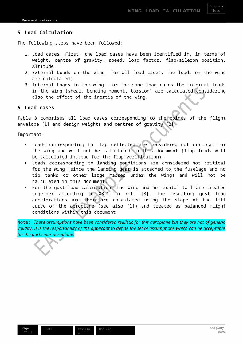
5. Load Calculation
The following steps have been followed:
1. Load cases: First, the load cases have been identified in, in terms of weight, centre of gravity, speed, load factor, flap/aileron position, Altitude.
2. External Loads on the wing: for all load cases, the loads on the wing are calculated;3. Internal Loads in the wing: for the same load cases the internal loads in the wing (shear, bending
moment, torsion) are calculated considering also the effect of the inertia of the wing;
6. Load cases
Table 3 comprises all load cases corresponding to the points of the flight envelope [1] and design weights and centres of gravity [2].
Important:
Loads corresponding to flap deflected are considered not critical for the wing and will not be calculated in this document (flap loads will be calculated instead for the flap verification).
Loads corresponding to landing conditions are considered not critical for the wing (since the landing gear is attached to the fuselage and no tip tanks or other large masses under the wing) and will not be calculated in this document.
For the gust load calculations the wing and horizontal tail are treated together according to X3.1 in ref. [3]. The resulting gust load accelerations are therefore calculated using the slope of the lift curve of the aeroplane (see also [1]) and treated as balanced flight conditions within this document.
Note: These assumptions have been considered realistic for this aeroplane but they are not of generic validity. It is the responsibility of the applicant to define the set of assumptions which can be acceptable for the particular aeroplane.

WING LOAD CALCULATIONCompany
logo
Document reference:
Page 11of 33
Date Revision company name
Doc.-No.
Altitude: The maximum permissible operational altitude is 13000ft. Despite the CS-LSA requirements do not require to accounts for the effects of altitude, such effects have been considered up to 10000 ft. in fact the gust load factor have been calculated at such altitude. This is considered acceptable since it covers the operational range within which the aeroplane will fly most of the time.
(Note: the CS-LSA requirement does not require to account for the effects of altitude. Calculating the loads at sea level would be acceptable. In this case, the choice to consider such effect up to 10000 ft is a decision of a designer, which would be accepted by the team.)
0 20 40 60 80 100 120 140 160 180
-4
-3
-2
-1
0
1
2
3
4
5
6
VFVCVA VD
VG
cleanpos. gustneg. gustflaps
Airspeed [KEAS]
load
fact
or []
Figure 1 – Reference flight envelope (WMTOW, FL 100)
cond
ition
Pax
(CG=
0.0
0m)
Fuel
(C
G= 0
.30m
)
Bagg
age
(CG=
0.5
0m)
Fron
t bal
last
w
eigh
t(C
G= -1
.00m
)
Rear
bal
last
w
eigh
t (CG
= 2.
80m
)
airc
raft
wei
ght
airc
raft
CG(a
t MAC
)
kg kg kg kg kg kg m
Desig
n W
&B
enve
lope
W MTOW , aft 122 full 80 max 20 0 18 600 0.390W MTOW , fwd 137 full 80 empty 0 23 0 600 0.250W ZWF, fwd 230 empty 0 4 0 600 0.250W ZWF, aft 189 max 20 0 25 600 0.390Wmin ,aft min 55 empty 0 0 7 428 0.390Wmin , fwd min 55 empty 0 35 0 456 0.250WminFF min 55 full 80 empty 0 0 0 495 0.345
Table 2 – Design weights (explained in ref. [2] )
company name
WING LOAD CALCULATIONCompany
logo
Document reference:
Page 12of 33
DateRevisionDoc.-No.
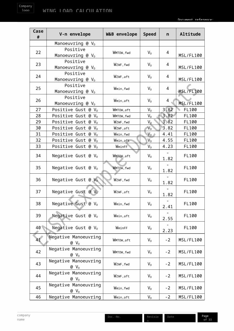
Case# V-n envelope W&B envelope Speed n Altitude
1 Positive Manoeuvring @ VA
WMTOW,aft VA 4 MSL/FL100
2 Positive Manoeuvring @ VA
WMTOW,fwd VA 4 MSL/FL100
3 Positive Manoeuvring @ VA
WZWF,fwd VA 4 MSL/FL100
4 Positive Manoeuvring @ VA
WZWF,aft VA 4 MSL/FL100
5 Positive Manoeuvring @ VA
Wmin,fwd VA 4 MSL/FL100
6 Positive Manoeuvring @ VA
Wmin,aft VA 4 MSL/FL100
7 Positive Gust @ VC WMTOW,aft VC 5.24 FL1008 Positive Gust @ VC WMTOW,fwd VC 5.24 FL1009 Positive Gust @ VC WZWF,fwd VC 5.24 FL100
10 Positive Gust @ VC WZWF,aft VC 5.24 FL10011 Positive Gust @ VC Wmin,fwd VC 6.11 FL10012 Positive Gust @ VC Wmin,aft VC 6.33 FL10013 Positive Gust @ VC WminFF VC 5.84 FL10014 Negative Gust @ VC WMTOW,aft VC -3.24 FL10015 Negative Gust @ VC WMTOW,fwd VC -3.24 FL10016 Negative Gust @ VC WZWF,fwd VC -3.24 FL10017 Negative Gust @ VC WZWF,aft VC -3.24 FL10018 Negative Gust @ VC Wmin,fwd VC -4.11 FL10019 Negative Gust @ VC Wmin,aft VC -4.33 FL10020 Negative Gust @ VC WminFF VC -3.84 FL100
21 Positive Manoeuvring @ VD
WMTOW,aft VD 4 MSL/FL100
22 Positive Manoeuvring @ VD
WMTOW,fwd VD 4 MSL/FL100
23 Positive Manoeuvring @ VD
WZWF,fwd VD 4 MSL/FL100
24 Positive Manoeuvring @ VD
WZWF,aft VD 4 MSL/FL100
25 Positive Manoeuvring @ VD
Wmin,fwd VD 4 MSL/FL100
26 Positive Manoeuvring @ VD
Wmin,aft VD 4 MSL/FL10027 Positive Gust @ VD WMTOW,aft VD 3.82 FL10028 Positive Gust @ VD WMTOW,fwd VD 3.82 FL10029 Positive Gust @ VD WZWF,fwd VD 3.82 FL10030 Positive Gust @ VD WZWF,aft VD 3.82 FL10031 Positive Gust @ VD Wmin,fwd VD 4.41 FL10032 Positive Gust @ VD Wmin,aft VD 4.55 FL10033 Positive Gust @ VD WminFF VD 4.23 FL10034 Negative Gust @ VD WMTOW,aft VD -1.82 FL100

WING LOAD CALCULATIONCompany
logo
Document reference:
Page 13of 33
Date Revision company name
Doc.-No.
Case# V-n envelope W&B envelope Speed n Altitude
35 Negative Gust @ VD WMTOW,fwd VD -1.82 FL10036 Negative Gust @ VD WZWF,fwd VD -1.82 FL10037 Negative Gust @ VD WZWF,aft VD -1.82 FL10038 Negative Gust @ VD Wmin,fwd VD -2.41 FL10039 Negative Gust @ VD Wmin,aft VD -2.55 FL10040 Negative Gust @ VD WminFF VD -2.23 FL10041 Negative Manoeuvring @ VD WMTOW,aft VD -2 MSL/FL10042 Negative Manoeuvring @ VD WMTOW,fwd VD -2 MSL/FL10043 Negative Manoeuvring @ VD WZWF,fwd VD -2 MSL/FL10044 Negative Manoeuvring @ VD WZWF,aft VD -2 MSL/FL10045 Negative Manoeuvring @ VD Wmin,fwd VD -2 MSL/FL10046 Negative Manoeuvring @ VD Wmin,aft VD -2 MSL/FL10047 Negative Manoeuvring @ VG WMTOW,aft VG -2 MSL/FL10048 Negative Manoeuvring @ VG WMTOW,fwd VG -2 MSL/FL10049 Negative Manoeuvring @ VG WZWF,fwd VG -2 MSL/FL10050 Negative Manoeuvring @ VG WZWF,aft VG -2 MSL/FL10051 Negative Manoeuvring @ VG Wmin,fwd VG -2 MSL/FL10052 Negative Manoeuvring @ VG Wmin,aft VG -2 MSL/FL100
Table 3 – Load cases
Note: For this revision of this example document, asymmetric load cases have not been calculated.

company name
WING LOAD CALCULATIONCompany
logo
Document reference:
Page 14of 33
DateRevisionDoc.-No.
6.1. Loads on the aeroplane
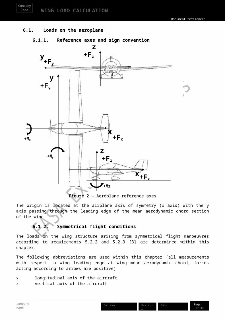
6.1.1. Reference axes and sign convention
Figure 2 – Aeroplane reference axes
The origin is located at the airplane axis of symmetry (x axis) with the y axis passing through the leading edge of the mean aerodynamic chord section of the wing.
6.1.2. Symmetrical flight conditions
The loads on the wing structure arising from symmetrical flight manoeuvres according to requirements 5.2.2 and 5.2.3 [3] are determined within this chapter.
The following abbreviations are used within this chapter (all measurements with respect to wing leading edge at wing mean aerodynamic chord, forces acting according to arrows are positive)
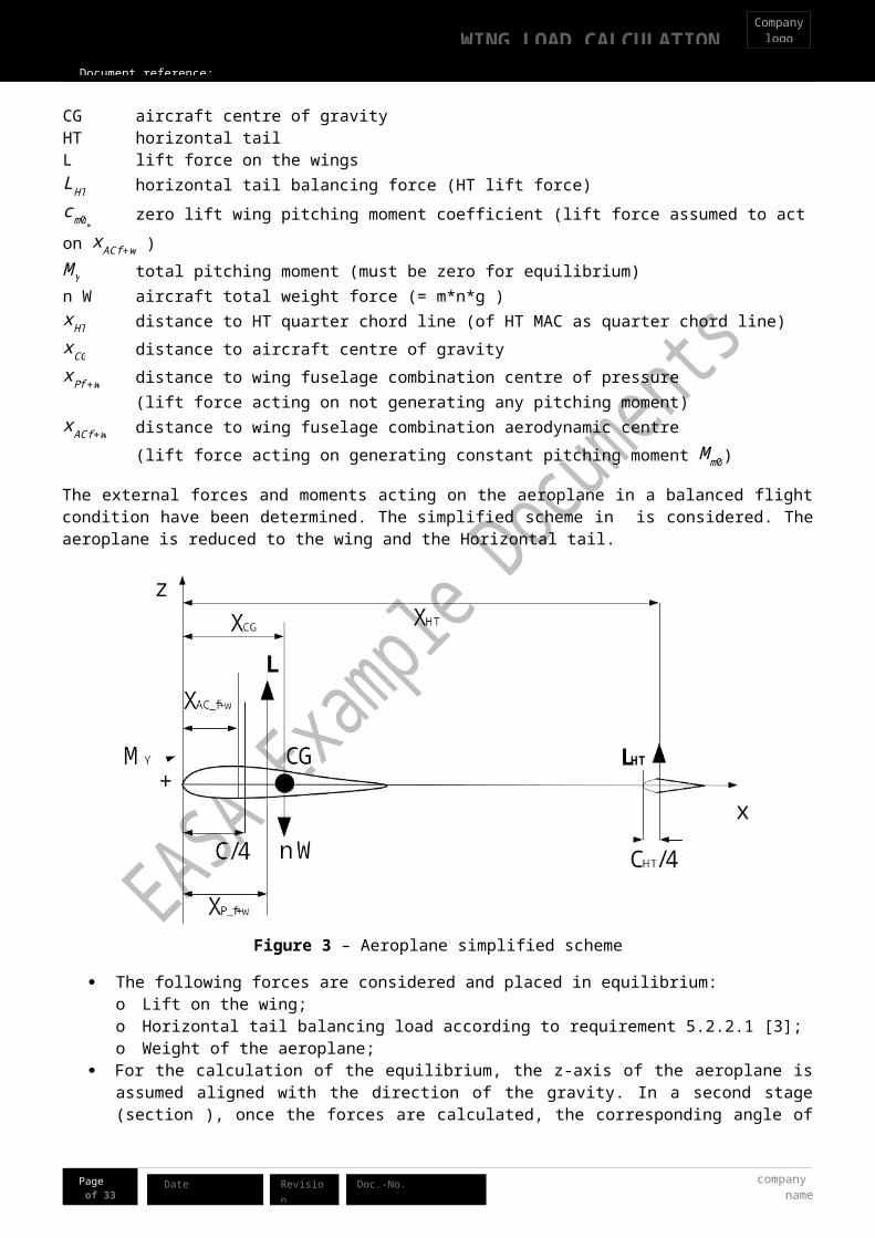
x longitudinal axis of the aircraftz vertical axis of the aircraftCG aircraft centre of gravityHT horizontal tailL lift force on the wingsLHT horizontal tail balancing force (HT lift force)cm0w zero lift wing pitching moment coefficient (lift force assumed to act on x ACf +w )
+My
+Mx
+Mz
yz
+Fy
+Fy
+Fz
+Fz
+Fx
+Fx
y
z
x
x
WING LOAD CALCULATIONCompany
logo
Document reference:
Page 15of 33
Date Revision company name
Doc.-No.
M Y total pitching moment (must be zero for equilibrium)n W aircraft total weight force (= m*n*g )xHT distance to HT quarter chord line (of HT MAC as quarter chord line)xCG distance to aircraft centre of gravityxPf+w distance to wing fuselage combination centre of pressure (lift force acting on not generating any pitching moment)x ACf +w distance to wing fuselage combination aerodynamic centre (lift force acting on generating constant pitching moment Mm0)
The external forces and moments acting on the aeroplane in a balanced flight condition have been determined. The simplified scheme in is considered. The aeroplane is reduced to the wing and the Horizontal tail.
Figure 3 – Aeroplane simplified scheme
The following forces are considered and placed in equilibrium: o Lift on the wing;o Horizontal tail balancing load according to requirement 5.2.2.1 [3];o Weight of the aeroplane;
For the calculation of the equilibrium, the z-axis of the aeroplane is assumed aligned with the direction of the gravity. In a second stage (section ), once the forces are calculated, the corresponding angle of attack will be considered for the calculation of the correct direction of the forces on the wing;
Influence of thrust and drag (of the total airplane) are considered negligible at this stage of calculation of the vertical forces. The effect of the drag will be considered in a second stage on the wing only;
The wing lift is assumed to act on the aerodynamic centre of the wing as a starting point. The contribution of the fuselage is accounted for as a shift of the point of aerodynamic centre. This is better explained in section .
The HT lift is applied at 25% of the chord; Effects of structural flexure are considered negligible; Angular accelerations are disregarded until the aeroplane has attained the prescribed load factor
(according to requirement 5.2.2.3 [3]);

company name
WING LOAD CALCULATIONCompany
logo
Document reference:
Page 16of 33
DateRevisionDoc.-No.
Note: The assumptions above provide a clear simplification to the calculations. The fact that they are used here does not mean that they can always be used. It is the responsibility of the designer to make the appropriate assumptions and to agree them with the Agency.
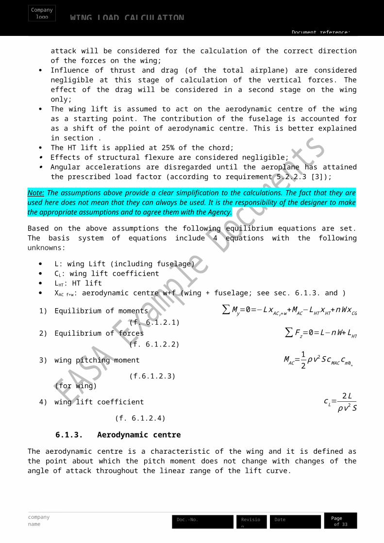
Based on the above assumptions the following equilibrium equations are set. The basis system of equations include 4 equations with the following unknowns:
L: wing Lift (including fuselage) CL: wing lift coefficient LHT: HT lift XAC f+w: aerodynamic centre w+f (wing + fuselage; see sec. 6.1.3 and )
1) Equilibrium of moments ∑M y=0=−Lx AC f+w+M AC−LHT xHT+nW xCG (f. 6.1.2.1)2) Equilibrium of forces ∑ F z=0=L−nW+LHT (f. 6.1.2.2)
3) wing pitching moment M AC=12ρ v2S cMAC cm0w (f.6.1.2.3)
(for wing)
4) wing lift coefficient c L=2Lρ v2S
(f. 6.1.2.4)
6.1.3. Aerodynamic centre
The aerodynamic centre is a characteristic of the wing and it is defined as the point about which the pitch moment does not change with changes of the angle of attack throughout the linear range of the lift curve.
According to [5] the aerodynamic centre can be estimated by adding a correction factor (shift) to the quarter chord point of the mean aerodynamic chord. The correction factor is a function of the maximum thickness of the profile which in this wing is 16% of the chord. For a tapered wing, the mean aerodynamic chord corresponds to
the mean chord and it is Sb2
=1.4m (see [6]). For this wing the correction factor is 0.012 (from Fig.2 [5] at 16%
thickness), so the mean aerodynamic centre of the wing without fuselage is
x AC=(0.250−0.012)∗1.4=0.333m (f. 6.1.3.1)
6.1.4. Pitching moment of the wing
The pitching moment of the profile from two dimensional wind tunnel test data [7] does not represent the moment of a three dimensional with the profile. The pitching moment of the whole wing is calculated according to DATCOM method 1 (formula 4.1.4.1.a [8]).
cm0w=AR cos2 (φc/4 )AR+2cos (φc/4 )
cm0=7.70∗cos2 (−0.74 )7.70+2∗cos (−0.74 )
∗(−0.055 )=−0.0437
(formula 4.1.4.1.a [8]) (f. 6.1.4.1)
With quarter chord sweep angle of the wing φc /4=−tan−1( croot−c tipb2
14 )=−0.74deg.

WING LOAD CALCULATIONCompany
logo
Document reference:
Page 17of 33
Date Revision company name
Doc.-No.
6.1.5. Influence of the fuselage
The fuselage is assumed to provide negligible lift. On the other hand, its influence on the aeroplane equilibrium is accounted for as a contribution to the pitching moment. In particular the following formula (taken from ref [9]) provides the shift of the aerodynamic centre of the wing due to fuselage pitching moment.
∆ x N fuse=−K f bfuse
2 crootS
1.05=0.078m (f. 6.1.5.1)
With crootl fuse
=0.22 and lNlfuse
=0.4 as input to the diagram in [9] yielding K f=0.65 and a correction factor of 1.05
due to low-wing configuration.
The shift of aerodynamic centre, due to the fuselage, is calculated as:
x AC f+w=x AC+∆ xN fuse=0 .333−0.078=0.255m (f. 6.1.5.2)
6.2. Forces and moments acting on the wings
In previous chapter the Lift and the lift coefficient have been determined. Having those as inputs, the drag and angle of attack are calculated.
Total wing drag coefficient cD=0.01+c L2
π AR(FIG. X2.1 of [3])(f. 6.2.1)
Drag force on the wings D=12cDρ v2S (FIG. X2.1 of [3]) (f. 6.2.2)
The angle of attack (using αCL=0as reference instead of α=0) for each load case is calculated using the following
formula:
α=c L
( dc L
da )+αCL=0 (FIG. X2.1 of [3]) (f. 6.2.3)
Where:
lift curve slope d cLdα
=0.1 ARAR+2
=0.1 7.77.7+2
=0.0791/deg (FIG. X2.1 of [3]) (f. 6.2.4)
and the zero-lift angle of the wing is taken as α cL=0=−2deg. This value is the zero-lift angle of the corresponding wing profile, taken from ref [7] (p.236).
company name
WING LOAD CALCULATIONCompany
logo
Document reference:
Page 18of 33
DateRevisionDoc.-No.
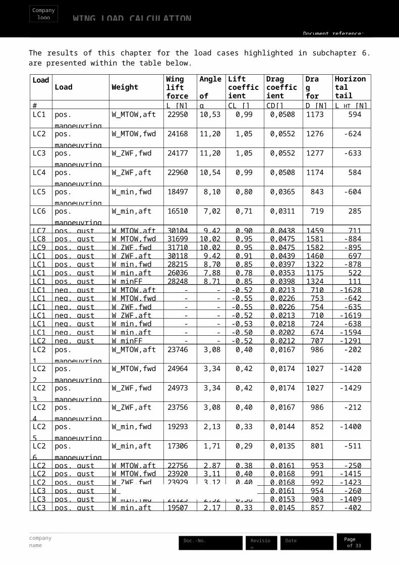
The results of this chapter for the load cases highlighted in subchapter 6 are presented within the table below.
Load case
Load Weight Wing lift force
Angle of attack
Lift coefficient
Drag coefficient
Drag force
Horizontal tail lift force
# L [N] α [deg] CL [] CD[] D [N] L_HT [N]LC1 pos. manoeuvring
@V_AW_MTOW,aft 22950 10,53 0,99 0,0508 1173 594
LC2 pos. manoeuvring @V_A
W_MTOW,fwd 24168 11,20 1,05 0,0552 1276 -624
LC3 pos. manoeuvring @V_A
W_ZWF,fwd 24177 11,20 1,05 0,0552 1277 -633
LC4 pos. manoeuvring @V_A
W_ZWF,aft 22960 10,54 0,99 0,0508 1174 584
LC5 pos. manoeuvring @V_A
W_min,fwd 18497 8,10 0,80 0,0365 843 -604
LC6 pos. manoeuvring @V_A
W_min,aft 16510 7,02 0,71 0,0311 719 285
LC7 pos. gust @V_C W_MTOW,aft 30104 9,42 0,90 0,0438 1459 711LC8 pos. gust @V_C W_MTOW,fwd 31699 10,02 0,95 0,0475 1581 -884LC9 pos. gust @V_C W_ZWF,fwd 31710 10,02 0,95 0,0475 1582 -895LC10 pos. gust @V_C W_ZWF,aft 30118 9,42 0,91 0,0439 1460 697LC11 pos. gust @V_C W_min,fwd 28215 8,70 0,85 0,0397 1322 -878LC12 pos. gust @V_C W_min,aft 26036 7,88 0,78 0,0353 1175 522LC13 pos. gust @V_C W_minFF 28248 8,71 0,85 0,0398 1324 111LC14 neg. gust @V_C W_MTOW,aft -17415 -8,57 -0,52 0,0213 710 -1628LC15 neg. gust @V_C W_MTOW,fwd -18401 -8,95 -0,55 0,0226 753 -642LC16 neg. gust @V_C W_ZWF,fwd -18408 -8,95 -0,55 0,0226 754 -635LC17 neg. gust @V_C W_ZWF,aft -17424 -8,58 -0,52 0,0213 710 -1619LC18 neg. gust @V_C W_min,fwd -17753 -8,70 -0,53 0,0218 724 -638LC19 neg. gust @V_C W_min,aft -16567 -8,25 -0,50 0,0202 674 -1594LC20 neg. gust @V_C W_minFF -17357 -8,55 -0,52 0,0212 707 -1291LC21 pos. manoeuvring
@V_DW_MTOW,aft 23746 3,08 0,40 0,0167 986 -202
LC22 pos. manoeuvring @V_D
W_MTOW,fwd 24964 3,34 0,42 0,0174 1027 -1420
LC23 pos. manoeuvring @V_D
W_ZWF,fwd 24973 3,34 0,42 0,0174 1027 -1429
LC24 pos. manoeuvring @V_D
W_ZWF,aft 23756 3,08 0,40 0,0167 986 -212
LC25 pos. manoeuvring @V_D
W_min,fwd 19293 2,13 0,33 0,0144 852 -1400
LC26 pos. manoeuvring @V_D
W_min,aft 17306 1,71 0,29 0,0135 801 -511
LC27 pos. gust @V_D W_MTOW,aft 22756 2,87 0,38 0,0161 953 -250LC28 pos. gust @V_D W_MTOW,fwd 23920 3,11 0,40 0,0168 991 -1415LC29 pos. gust @V_D W_ZWF,fwd 23929 3,12 0,40 0,0168 992 -1423LC30 pos. gust @V_D W_ZWF,aft 22766 2,87 0,38 0,0161 954 -260LC31 pos. gust @V_D W_min,fwd 21125 2,52 0,36 0,0153 903 -1409LC32 pos. gust @V_D W_min,aft 19507 2,17 0,33 0,0145 857 -402LC33 pos. gust @V_D W_minFF 21219 2,54 0,36 0,0153 906 -694

WING LOAD CALCULATIONCompany
logo
Document reference:
Page 19of 33
Date Revision company name
Doc.-No.
Load case
Load Weight Wing lift force
Angle of attack
Lift coefficient
Drag coefficient
Drag force
Horizontal tail lift force
# L [N] α [deg] CL [] CD[] D [N] L_HT [N]LC34 neg. gust @V_D W_MTOW,aft -8924 -3,88 -0,15 0,0109 647 -1809LC35 neg. gust @V_D W_MTOW,fwd -9480 -4,00 -0,16 0,0111 654 -1254LC36 neg. gust @V_D W_ZWF,fwd -9483 -4,00 -0,16 0,0111 654 -1250LC37 neg. gust @V_D W_ZWF,aft -8929 -3,88 -0,15 0,0109 647 -1805LC38 neg. gust @V_D W_min,fwd -9520 -4,01 -0,16 0,0111 655 -1250LC39 neg. gust @V_D W_min,aft -8895 -3,87 -0,15 0,0109 647 -1813LC40 neg. gust @V_D W_minFF -9185 -3,94 -0,16 0,0110 651 -1628LC41 neg. manoeuvring
@V_DW_MTOW,aft -9914 -4,09 -0,17 0,0112 660 -1858
LC42 neg. manoeuvring @V_D
W_MTOW,fwd -10523 -4,22 -0,18 0,0113 669 -1249
LC43 neg. manoeuvring @V_D
W_ZWF,fwd -10527 -4,22 -0,18 0,0113 669 -1245
LC44 neg. manoeuvring @V_D
W_ZWF,aft -9919 -4,09 -0,17 0,0112 660 -1853
LC45 neg. manoeuvring @V_D
W_min,fwd -7688 -3,62 -0,13 0,0107 633 -1259
LC46 neg. manoeuvring @V_D
W_min,aft -6694 -3,40 -0,11 0,0105 623 -1703
LC47 neg. manoeuvring @V_G
W_MTOW,aft -10963 -13,83 -0,94 0,0466 543 -809
LC48 neg. manoeuvring @V_G
W_MTOW,fwd -11572 -14,49 -0,99 0,0508 592 -200
LC49 neg. manoeuvring @V_G
W_ZWF,fwd -11576 -14,50 -0,99 0,0508 592 -196
LC50 neg. manoeuvring @V_G
W_ZWF,aft -10968 -13,84 -0,94 0,0466 543 -804
LC51 neg. manoeuvring @V_G
W_min,fwd -8736 -11,43 -0,75 0,0332 387 -210
LC52 neg. manoeuvring @V_G
W_min,aft -7743 -10,35 -0,66 0,0283 329 -655
Table 4 – Loads on the aeroplane
6.3. Unsymmetrical flight conditions
Note: These load cases will not be calculated within this revision of the example document.
company name
WING LOAD CALCULATIONCompany
logo
Document reference:
Page 20of 33
DateRevisionDoc.-No.
6.4. Wing load distribution
After having calculated the total load on the wing, the load distribution is calculated and shown in the following sections.
Every load is assumed to act on the span wise centre of each station.
Figure 4 – Location of wing stations
6.4.1. Wing lift distribution
The wing lift distribution is calculated here. The lift contribution of the fuselage is assumed to be zero (this means that the load which would act in correspondence of the fuselage, is shifted externally to the wing) leading to more conservative results on the wing loads since they provide higher bending.
Note: Alternatively, the applicant would have to determine the reduction in wing lift distribution at the location of the fuselage and demonstrate the validity of the approach.
Figure 5 – Effect of the fuselage, areas A (total lift calculated at the end of this chapter) and B (total lift according to Schrenk) are of equal size
WING LOAD CALCULATIONCompany
logo
Document reference:
Page 21of 33
Date Revision company name
Doc.-No.
This approach is based on the approximation described by Schrenk [10] and requires adjustments:
moving the apex of the elliptical distribution from the fuselage centre towards the wing root increasing lift of wetted wing sections to compensate for zero lift of fuselage wing section
The formula for wing lift distribution is derived from Schrenk [10] and is altered to assume zero lift at the wing section within the fuselage as shown below. The formula gives the value of the lift for span unit. “i” identifies the individual station.
Figure 6 – lschrenk lift distribution with zero lift at fuselage wing section
lschrenk i=12ρ v2
d cLdα (α−α cL=0 )
12 (c i+ 4π cMAC √1−( y i−
b02
b−b02
)2
) ( [10]) (f. 6.4.1.1)
Now the lift of the wing section within the fuselage is redistributed across the wetted wing area to achieve conservative results. The lift distribution calculated above is adjusted by multiplication of a correction factor derived from comparison between total lift of the whole wing including the fuselage section and the wetted wing only.
Figure 7 – Fuselage wing section lift redistributed across wetted wing stations
lschren k i' =total wing lift including fuselage section
total lift of wettedwing sectionsonlylschrenki
company name
WING LOAD CALCULATIONCompany
logo
Document reference:
Page 22of 33
DateRevisionDoc.-No.
or lschren k i' =
∑i=0
n
( lschrenk i∆ y¿i )
∑i=1
n
( lschrenk i∆ y¿i )l schrenk i (f. 6.4.1.2)
The lift distribution corresponding to the formula above, gives a value of lift at wing tip which is higher than zero and therefore does not fully reproduce the actual loading (the winglift is normally zero at the tip). Nevertheless this assumption does not give significant changes and yields conservative results.
The local angle of attack for the station I, as a result of this corrected Schrenk distribution, is given by the
following formula:
α i=lschren k i'
12ρ v2c i( c L
( dc L
da )+αCL=0) (from f.6.2.3 and f.6.1.2.4) (f. 6.4.1.3)
Note: FAA AC 23-19A, paragraph 23.301, contains other acceptable methods.
0 1 2 3 4 5 6
0
500
1000
1500
2000
2500
3000
lift line load
wing span [m]
lift li
ne lo
ad l'
_sch
renk
_i [N
/m]
Figure 8 – Span wise lift distribution lschrenk'
6.4.2. Wing drag distribution
Since the effect of the drag is negligible, when compared to the effect of the lift, the span wise drag distribution has been assumed constant throughout wing span. This is a conservative assumption. The drag loading per metre of span:
d= Db−b0
(f.
6.4.2.1)
6.4.3. Wing and fuel mass distribution
The local masses are calculated for each wing station to account for the mass of the structure of the wing including the systems and control surfaces (control systems, and other equipment). It is assumed that the wing

WING LOAD CALCULATIONCompany
logo
Document reference:
Page 23of 33
Date Revision company name
Doc.-No.
has a linear distribution proportional to the chord. At each station the point of application of the mass is 45% of the chord.
Figure 9 – Wing mass distribution
Figure 10 – Fuel distribution
A constant fuel distribution (at a point of application of 20% of the chord) is assumed throughout the fuel tank span.
Wing mass distribution with full fuel (40kg in each wing )
station width average span at station
average chord at station
mass of structure at station
fuel mass at station
# Δy_i [m] y_i [m] c_i [m] m_w_i [kg] m_fl_i [kg]0 0.50 0.25 1.56 fuselage1 0.50 0.75 1.53 5.6 20.02 0.50 1.25 1.50 5.5 20.03 0.50 1.75 1.47 5.4 0.04 0.50 2.25 1.44 5.3 0.05 0.50 2.75 1.41 5.2 0.06 0.50 3.25 1.38 5.1 0.07 0.50 3.75 1.35 5.0 0.08 0.50 4.25 1.32 4.9 0.09 0.50 4.75 1.30 4.8 0.0
10 0.39 5.20 1.27 3.7 0.0
Table 5 – Mass distribution with full fuel
direction of flight
main spar
direction of flight
fuel
main spar
Station 2 rib
20 % of the chord
45% of the chord
Station 2 ribStation 2 ribStation 2 ribStation 2 ribStation 2 ribStation 2 ribStation 2 ribStation 2 ribStation 2 ribStation 2 ribStation 2 ribStation 2 ribStation 2 ribStation 2 ribStation 2 ribStation 2 ribStation 2 ribStation 2 ribStation 2 ribStation 2 ribStation 2 ribStation 2 ribStation 2 ribStation 2 ribStation 2 ribStation 2 ribStation 2 ribStation 2 ribStation 2 ribStation 2 ribStation 2 ribStation 2 ribStation 2 ribStation 2 ribStation 2 ribStation 2 ribStation 2 ribStation 2 ribStation 2 ribStation 2 ribStation 2 ribStation 2 rib

company name
WING LOAD CALCULATIONCompany
logo
Document reference:
Page 24of 33
DateRevisionDoc.-No.
6.4.4. Wing torsion distribution
At each station, the wing lift is assumed to be acting at the local centre of pressure, which is calculated using the formula:
xPi=x AC i
−c icm0¿
cLi(from eq. 9.17.(d) [11]) (f.
6.4.4.1)
Where, ci is the chord at each station, cm0_w_i is the pitching moment around the aerodynamic centre of the wing section (it is -0.0436 across the wing from chapter 6.1.4), CL_i is the local lift coefficient and comes from the corrected Schrenk distribution (l 'schrenk i) in . Therefore centre of pressure location is dependent on the local angle of attack.
Each station’s lift force acts on its centre of pressure and imposes torsion around the wing elastic axis which for this aeroplane is located approximately at a constant chord percentage of 30% (see design data - the main spar is approximately at 25% of the chord) throughout the entire wing span with local positions xsi as local shear centres at the stations.
Note: the location of the elastic axis for this wing has been assumed at 30%. It is responsibility of the applicant to determine and justify the location of the elastic axis. Incremental torsion load on structure at each station with respect to local wing shear centre including contribution of fuel and wing structure inertia forces:
∆T Si=∆ y il ' schrenk i (xsi−x pi )−ng mfueli (xsi−x fuel i )−n gmwing i (x si−xCG¿ ) (f.6.4.4.2)
Torsion at each station i (with respect to shear centre) is:
T si= ∑i=num
i
∆T Si(f. 6.4.4.3)
6.4.5. Distribution of internal loads
The components of the internal loads on the wing structure are calculated in different steps for each station.
The flight load factor n is assumed to act in parallel to the direction of the lift force instead of the direction of the normal force (As required by 5.2.1.1 of ref. [3]). The difference is assumed negligible.
The incremental shear load parallel to lift force vector at station i is taking into account also the inertia unloading of the wing
∆QLi=∆ y i l'schren ki−ng (mfue li+mwin gi) (f. 6.4.5.1)
Incremental shear load parallel to drag force vector at station i:
∆QDi=d∆ y i (f. 6.4.5.2)
With ∆ y i representing the width of the station i.
The summation of incremental shear loads throughout the stations to obtain the absolute shear loads at station i is presented below.
Shear load parallel to lift force vector
WING LOAD CALCULATIONCompany
logo
Document reference:
Page 25of 33
Date Revision company name
Doc.-No.
QLi= ∑i=num
i
∆QLi (f.6.4.5.3)
Shear load parallel to drag force vector
QDi= ∑
i=num
i
∆QDi(f. 6.4.5.4)
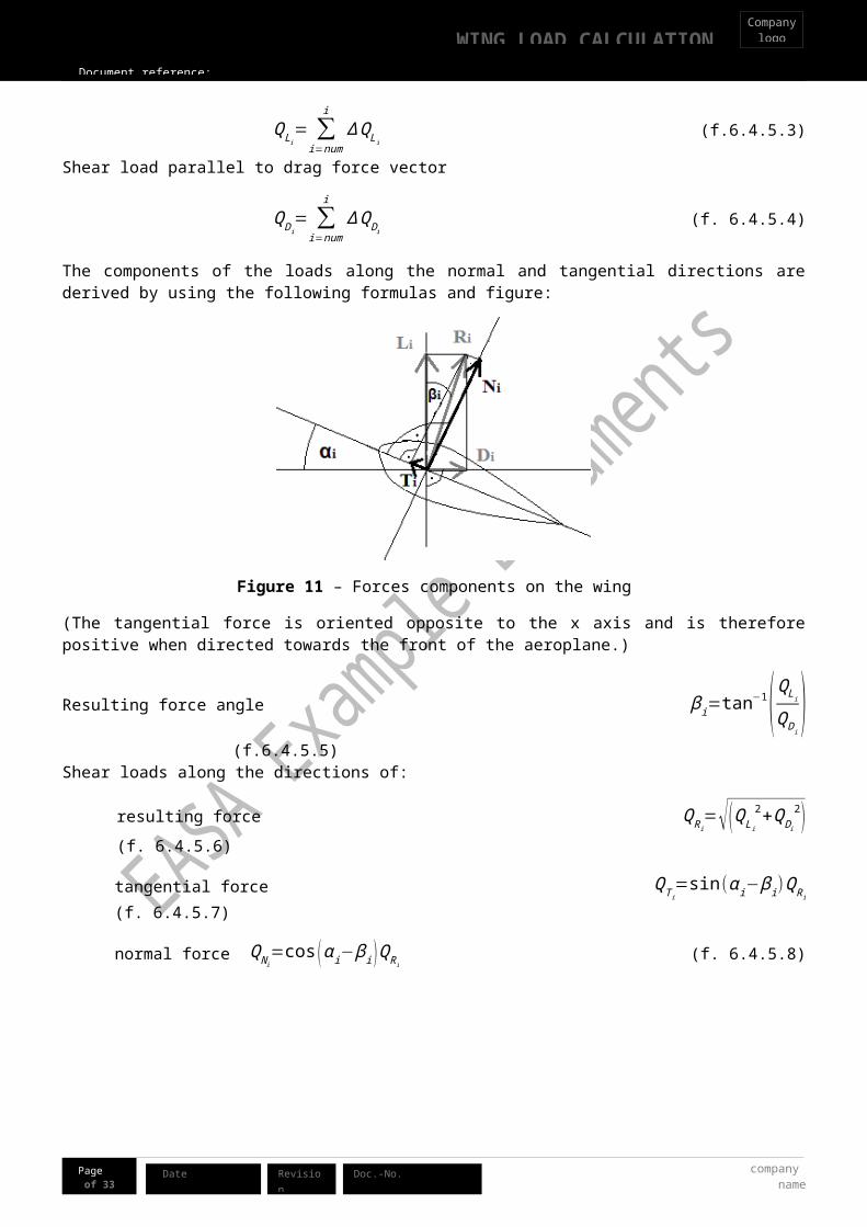
The components of the loads along the normal and tangential directions are derived by using the following formulas and figure:
Figure 11 – Forces components on the wing
(The tangential force is oriented opposite to the x axis and is therefore positive when directed towards the front of the aeroplane.)
Resulting force angle β i=tan−1(QL i
QD i) (f.6.4.5.5)
Shear loads along the directions of:
resulting force QRi=√ (QLi
2+QD i
2 ) (f. 6.4.5.6)
tangential force QT i=sin(α i−β i)QRi
(f. 6.4.5.7)
normal force QN i=cos (αi−βi )QRi
(f. 6.4.5.8)
With the local angle of attack for the station i as a result of the corrected Schrenk distribution given by the
following formula:
α i=lschren k i'
12ρ v2c i( c L
( dc L
da )+αCL=0)
(from f. 6.4.1.4)
Summation of shear loads to obtain the bending moments at each station and using the increased lever arm (∆ yn
instead of ∆ yn2
) at the wing tip station results in slightly more conservative values.
company name
WING LOAD CALCULATIONCompany
logo
Document reference:
Page 26of 33
DateRevisionDoc.-No.
Bending moment along normal direction
M zi= ∑i=num
i
(QN i∆ y i ) (f. 6.4.5.9)
Bending moment along tangential direction
M x i= ∑
i=num
i
(QT i∆ y i ) (f. 6.4.5.10)
The results are presented within the graphs and tables below.

EASA Example Documents
Document reference:
WING LOAD CALCULATIONCompany
logo
Page 27of 33
Date Revision Doc.-No. companyname
Figure 12 – Shear load distribution QLiin direction of lift force

EASA Example Documents
company name
Document reference:
WING LOAD CALCULATIONCompany
logo
Page 28of 33
DateRevisionDoc.-No.
Figure 13 – Shear load distribution QN i in direction of normal force

EASA Example Documents
Document reference:
WING LOAD CALCULATIONCompany
logo
Page 29of 33
Date Revision Doc.-No. companyname
Figure 14 – Shear load distribution QT i in direction of tangential force bending moment distribution MN i
in direction of normal force

EASA Example Documents
company name
Document reference:
WING LOAD CALCULATIONCompany
logo
Page 30of 33
DateRevisionDoc.-No.
Figure 15 – Bending moment distribution MN i in direction of normal force

EASA Example Documents
Document reference:
WING LOAD CALCULATIONCompany
logo
Page 31of 33
Date Revision Doc.-No. companyname
Figure 16 – Bending moment distribution M T i in direction of tangential force

EASA Example Documents
company name
Document reference:
WING LOAD CALCULATIONCompany
logo
Page 32of 33
DateRevisionDoc.-No.
Figure 17 – Torsion distribution T Si with reference to wing elastic axis

WING LOAD CALCULATIONCompany
logo
Document reference:
Page 33of 33
Date Revision company name
Doc.-No.
7. Compliance statements
Compliance statements are shown below:
Requirement reference Subject
CS-LSA F2245-12d5.1.1.1
5.1.1.1 Strength requirements are specified in terms of limit loads (the maximum loads to be expected in service) and ultimate loads (limit loads multiplied by prescribed factors of safety). Unless otherwise provided, prescribed loads are limit loads.
Statement of compliance
Calculated loads are limit loads. See chapter 6.
Requirement reference Subject
CS-LSA F2245-12d5.1.1.2
5.1.1.2 Unless otherwise provided, the air, ground, and water loads must be placed in equilibrium with inertia forces, considering each item of mass in the airplane. These loads must be distributed to conservatively approximate or closely represent actual conditions.
Statement of compliance
Calculations are based on equilibrium of air and inertia forces.Mass distribution is taken into consideration. See chapters 6.1, 6.2, .
Requirement reference Subject
CS-LSA F2245-12d5.1.1.4
5.1.1.3 The simplified structural design criteria given in Appendix X1 may be used for airplanes with conventional configurations. If Appendix X1 is used, the entire appendix must be substituted for the corresponding paragraphs of this subpart, that is, 5.2.1 to 5.7.3. Appendix X2 contains acceptable methods of analysis that may be used for compliance with the loading requirements for the wings and fuselage.
Statement of compliance
The simplified design criteria is not used.
Requirement reference Subject
CS-LSA F2245-12d5.2.1.1
5.2.1.1 Flight load factors, n, represent the ratio of the aerodynamic force component (acting normal to the assumed longitudinal axis of the airplane) to the weight of the airplane. A positive flight load factor is one in which the aerodynamic force acts upward, with respect to the airplane.
Statement of compliance
The requirement has been met. This is shown in chapter 6.4.5.
Requirement reference Subject
CS-LSA F2245-12d5.2.1.2
5.2.1.2 Compliance with the flight load requirements of this section must be shown at each practicable combination of weight and disposable load within the operating limitations specified in the POH.
Statement of compliance
Every combination of weight and centre of gravity was considered. See chapter 6.

company name
WING LOAD CALCULATIONCompany
logo
Document reference:
Page 34of 33
DateRevisionDoc.-No.
Requirement reference Subject
CS-LSA F2245-12d5.2.2.1
5.2.2.1 The appropriate balancing horizontal tail loads must be accounted for in a rational or conservative manner when determining the wing loads and linear inertia loads corresponding to any of the symmetrical flight conditions specified in 5.2.2 to 5.2.6.
Statement of compliance
Horizontal tail balancing, fuselage aerodynamic and inertia loads were considered in determining the wing loads. See chapter 6.1.
Requirement reference Subject
CS-LSA F2245-12d5.2.2.2
5.2.2.2 The incremental horizontal tail loads due to maneuvering and gusts must be reacted by the angular inertia of the airplane in a rational or conservative manner.
Statement of compliance
In calculating the loads on the wing in gust and manoeuvre, the angular inertia of the aeroplane has been disregarded. This is considered acceptable for the wing loads. See chapter 6.1.
Requirement reference Subject
CS-LSA F2245-12d5.2.2.3
5.2.2.3 In computing the loads arising in the conditions prescribed above, the angle of attack is assumed to be changed suddenly without loss of air speed until the prescribed load factor is attained. Angular accelerations may be disregarded.
Statement of compliance
The loss of speed has been has been disregarded and also the angular accelerations during symmetrical flight. See chapter 6.1.
Requirement reference Subject
CS-LSA F2245-12d5.2.2.4
5.2.2.4 The aerodynamic data required for establishing the loading conditions must be verified by tests, calculations, or by conservative estimation. In the absence of better information, the maximum negative lift coefficient for rigid lifting surfaces may be assumed to be equal to −0.80. If the pitching moment coefficient, Cmo, is less than ±0.025, a coefficient of at least ±0.025 must be used.
Statement of compliance
Aerodynamic data is sourced from conservative estimates based on tests [7]. Negative lift coefficient was sourced from aerodynamic tests [7].Moment coefficient Cmo is greater than ±0.025 (-0.055) [7]. See chapters 6.1, 6.2 and .
Requirement reference Subject
CS-LSA F2245-12d5.2.3.1
5.2.3.1 General – Compliance with the strength requirements of this subpart must be shown at any combination of airspeed and load factor on and within the boundaries of a flight envelope similar to the one in Fig. 1 that represents the envelope of the flight loading conditions specified by the maneuvering and gust criteria of 5.2.5 and 5.2.6 respectively.
Statement of compliance
Every combination of airspeed and load factor on and within the boundaries of the flight envelope was considered. See chapter 6.
WING LOAD CALCULATIONCompany
logo
Document reference:
Page 35of 33
Date Revision company name
Doc.-No.
company name
WING LOAD CALCULATIONCompany
logo
Document reference:
Page 36of 33
DateRevisionDoc.-No.
Requirement reference Subject
CS-LSA F2245-12d5.2.7
5.2.7 Unsymmetrical Flight Conditions – The airplane is assumed to be subjected to the unsymmetrical flight conditions of 5.2.7.1 and 5.2.7.2. Unbalanced aerodynamic moments about the centre of gravity must be reacted in a rational or conservative manner considering the principal masses furnishing the reacting inertia forces.
Statement of compliance
Note: Unsymmetrical loads have not been calculated in this revision of the document
Requirement reference Subject
CS-LSA F2245-12d5.2.7.1
5.2.7.1 Rolling Conditions – The airplane shall be designed for the loads resulting from the roll control deflections and speeds specified in 5.7.1 in combination with a load factor of at least two thirds of the positive maneuvering load factor prescribed in 5.2.5.1. The rolling accelerations may be obtained by the methods given in X2.3. The effect of the roll control displacement on the wing torsion may be accounted for by the method of X2.3.2 and X2.3.3.
Statement of compliance
Note: Unsymmetrical loads have not been calculated in this revision of the document
Requirement reference Subject
CS-LSA F2245-12d5.2.7.2
5.2.7.2 Yawing Conditions – The airplane must be designed for the yawing loads resulting from the vertical surface loads specified in 5.5.
Statement of compliance
Note: Unsymmetrical loads have not been calculated in this revision of the document