wireless sensor networks in oil pipeline systems using electromagnetic ... · pdf filewireless...
TRANSCRIPT
Wireless Sensor Networks in Oil Pipeline Systems Using Electromagnetic Waves
Mustafa Alper Akkaş1, Radosveta Sokullu2, Abdullah Balcı3
1Pamukkale University Department of Electrical & Electronic Engineering, DENIZLI 20070, TURKEY [email protected]
2,3Ege University, Department of Electrical & Electronics Engineering, IZMIR 35040, Turkey [email protected], [email protected]
Abstract
The realization of WUSNs (Wireless Underground Sensor Networks) will lead to many emerging applications, such as intelligent agriculture, underground pipelines, oil reservoir monitoring, concealed border patrol, earthquake and landslide forecasting, underground mine disaster prevention and rescue etc. The hostile underground environments prevent the direct use of most, if not all, existing wireless communication and networking solutions, due to the extremely high path loss, small communication range, and high dynamics of electromagnetic (EM) waves when penetrating the soil, sand, rock, water, crude oil medium in the underground environment and in pipelines. The objective of the paper is to address these unique and important challenges for the realization of wireless sensor networks in Oil Pipeline Systems. Research also focuses on developing a general framework using wireless sensor networks to provide continuous monitoring.
Key-Words: - Oil pipeline systems, Pipeline transport, Wireless underground sensor networks, Electromagnetic Absorbance.
1. Introduction
WUSNs are envisioned to operate in quite different
underground environments, including soil medium, oil reservoirs, and underground mines and tunnels. The system architecture of general WUSNs in soil medium as detailed in [1, 2, 3, 4] consists of a large number of wireless sensor nodes that are buried in the underground soil medium. As defined in [1, 2, 3, 4] WUSNs are networks of wireless sensor nodes operating below the ground surface. Compared to the current underground sensor networks which use wired communication methods for network deployment, WUSNs have advantages in timeliness of data, ease of deployment and data collection, concealment, reliability, and coverage density [1, 2, 3, 4]. As a natural extension to the well-established wireless sensor networks (WSNs) [3,4,5] paradigm, WUSNs can be deployed to operate in pipeline systems and are also envisioned to provide real-time monitoring capabilities. WUSNs are a promising and continuously expanding field that will enable a wide variety of novel applications, which are not possible with current underground monitoring techniques.
Pipeline transport is the transportation of goods through a
pipe. Liquids and gases are transported in pipelines and any chemically stable substance can be sent through a pipeline.
Pipelines exist for the transport of crude and refined petroleum, fuels: such as oil, natural gas and bio fuels and other fluids including sewage, slurry, water, and beer. Pipelines are useful for transporting water for drinking or irrigation over long distances when it needs to move over hills, or where canals or channels are poor choices due to considerations of evaporation, pollution, or environmental impact. Pneumatic tubes using compressed air can be used to transport solid capsules. Oil pipelines are made from steel or plastic tubes which are usually buried. The oil is moved through the pipelines by pump stations along the pipeline. Pipelines conveying flammable or explosive material, such as natural gas or oil, pose special safety concerns and there have been various accidents. Pipelines can be the target of vandalism, sabotage, or even terrorist attacks. In war, pipelines are often the target of military attacks. For Oil & Gas Industry, the most common and important applications are related to the monitoring of real-time process control, safety, maintenance and production performance [6].
2. Related Work
Yuanwei Jinet et al. [7], describes a sensor network platform
for pipeline system monitoring with Lamb waves which are guided ultrasonic waves that can propagate for considerable distances in plates. Pipeline systems are widely used for distribution and transportation of petroleum, natural gas, water, and sewage. Leaks and ruptures due to an aging and fast decaying pipeline system infrastructure cost millions of dollars a year; they also make clear the necessity for continuous, automatic monitoring systems that can provide early detection and early warning of defects, such as corrosion and leaks, before they reach the magnitude of a major disaster. In the paper, discussed how sensor networks can detect, localize, and quantify bursts, leaks and other anomalies in pipeline systems with Lamb waves.
Anupama K. R., et al. [8] paper proposes a Pipeline
Monitoring system using the technology of Wireless Sensor Networks. The research involves the development of a Remote Condition Based Monitoring application for Oil and Gas pipelines using over 100 Wireless Sensor Network Motes. The paper describes the research methodology and a step-wise system development procedure. It starts with the description of an application specific Test Bed for the Pipeline Monitoring System.
Huaping Yu, et al. [9] proposes an efficient pipeline state
information collection algorithm based on sensor node line deployment strategy and data fusion strategy in WSN. And the
143
analysis result of this algorithm shows that the proposed algorithm can remarkably improve the network performances on delay and energy, ensure the urgency data to be propagated effectively and prolong the network life span. It is characterized with high performance, low cost and control efficiency.
Most of the studies mentioned above do not model the
channel in pipelines. With the modeling of wireless sensor devices the trend is towards simpler and much cheaper solutions by software based on standardized nodes and networks.
3. Wireless Underground Sensor Networks Applications
Underground WSN have been used mainly for agriculture purposes, environmental monitoring or military purposes: WSN used in smart agriculture, in golf courts, in smart irrigation systems, in mines and in border areas.
In the application described in [10], wireless nodes are buried in the soil at fixed distances and provide real-time information about specific parameters of the soil like humidity, temperature, mineral composition, etc. Underground sensor collect information and transmit it to above sink situated above the ground. Based on the collected date the control center can regulate the operational conditions of the hothouse – increasing or decreasing the temperature, regulating the watering process or if the content of specific minerals is reduced those can be fed automatically to the soil.
Another application of WUSN, the golf court application, is
described in [11]. In the golf course the humidity of the soil and the condition of the grass is of utmost importance. Thus in their work, Ugmo et al, use the WUSN with specially designed sensors to ensure that the appropriate values of the humidity, salinity and temperature, most appropriate for the type of grass used, are in place. Even though it might look a little bit trivial as an implementation this is an example of a very complex in operation WUSN.
In irrigation systems it is very important to have precise
information about the condition of the watering pipes as well as the amount of water which is passing though at every time. Thus in [12] an example study was carried out which can be applied to underground watering pipes from providing up-to-date information about the amount of water being pumped.
Earth slide, gas eruption or flooding are among the most
dangers situations that can occur in mines. In order to prevent such disasters WSN networks can be used. One of the applications developed is described in [13].The WSN consists of sensor nodes placed on the walls and pillars in the shaft and provides information about the number of people working in that area, about the temperature, humidity, pressure and gas composition. The system can be used for monitoring and with proper data analysis it can also be used as a warning system in case of upcoming disasters. Thanks to such systems, possible disasters in mines can be predicted beforehand.
Another application area that can highly benefit from a small
network is the exploration of underground oil reservoirs. Sensor nodes deployed underground in the petroleum containing area can provide valuable information about certain characteristics of the reserve. This application would require that wireless sensor nodes are deployed underground in a 3-D hydraulic fracture
with the size 100 m × 3 m × 1 cm (length × height × width). Since the width of the structure is less than 1 cm, the size of the sensor agents falls in the millimeter magnitude. In the oil recovery process there are also side fractures, where the width of the structure is very small, so the size of the sensor agents falls in the very small magnitude [3]. A promising approach to increase the oil recovery factor is to use WUSN and deploy sensing agents in the 3-D hydraulic fracture of oil field to enable real-time oil reservoir monitoring and provide comprehensive sensing measurements such as pressure, temperature, oil saturation and fluid type.
4. EM Wave-Based Technique in Oil Pipeline Systems
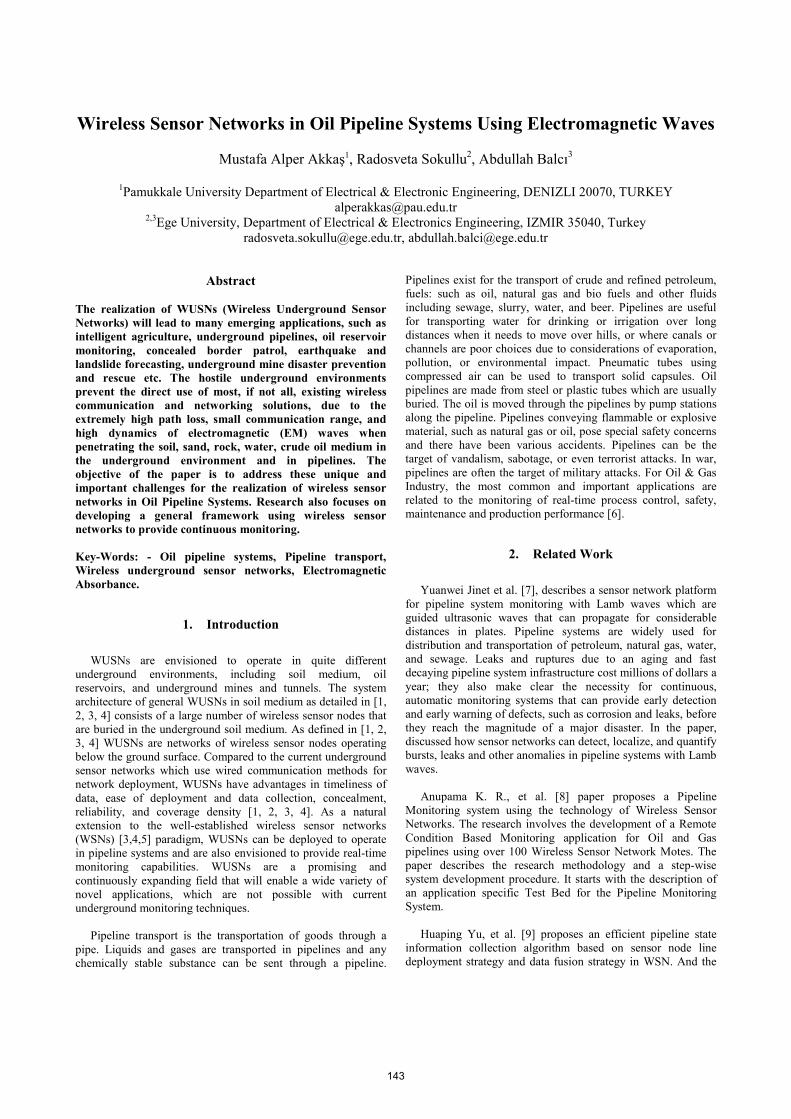
The system architecture of WUSNs in Oil Pipeline Systems
is illustrated in Fig. 1. Blue part (Medium 1) shows the oil and black lines shows the pipeline which are made from steel or plastic tubes. Medium 2 is think as steel which relative magnetic permeability taken as 5000.
Fig. 1. System architecture of the wireless sensor network for oil Pipeline Systems.
Red Underground Wireless Sensors which can be send the
the temperature, humidity, pressure and oil composition to the surface sink. By this way pipeline safety solutions like pipeline damage prevention and leak detection can be calculate. Surface sinks antenna can be located as two different ways first their antenna can be located inside the pipe through from a hole or can be located outside the pipe as seen in the Fig. 1.
4.1. Calculation of Channel Absorption Properties in Oil
The unique characteristics of signal propagation in oil require
derivation of the path loss considering the properties of oil. From the Friis equation [14], it is well known that the received signal strength in free space at a distance r from the transmitter is expressed in the logarithmic form as
r t r t woP P G G L= + + − (1) where Pt is the transmit power, Gr and Gt are the gains of the
receiver and transmitter antennas, and Lwo is the path loss in free space in dB, which is given by
[ ]1020 log4
woL f d dBcπ
=⋅⎛ ⎞⋅⎜ ⎟
⎝ ⎠ (2)
144

where d is the distance between the transmitter and the
receiver in meters, f is the operation frequency in MHz ,and c is the speed of light in a vacuum, 3× 10⁸ meters per second. For the propagation in oil, a correction factor should be included in the Friis equation (1) to account for the effect of the oil medium. As a result, the received signal can be rewritten as
wo 0 oil, L = L + Lr t r t woP P G G L= + + − (3) where Lwo = L0 + Loil . Loil stands for the additional path loss
caused by the propagation in oil, which is calculated by considering the following differences of EM wave propagation in oil compared to that in air: (1) the signal velocity, and hence, the wavelength λ, is different and (2) the amplitude of the wave will be attenuated according to the frequency. The additional path loss, Loil, in oil is, hence, composed of two components which is Loil=Lβ+Lα. Where Lβ is the attenuation loss due to the difference of the wavelength of the signal in water, λ, compared to the wavelength in free space, λ0, and Lα is the transmission loss caused by attenuation with attenuation constant α. Consequently, Lβ = 20 log(λ0/λ) and Lα = e2αd. The wavelength is λ = 2π/β and in free space λ0 = c/f , where β is the phase shifting constant, c = 3 × 10⁸ m/s, and f is the operating frequency, the Lβ and Lα can be represented in dB as follows:
154 20log( ) 20log( ) ( )8.69 ( )oil
L f dBL L L
L d dBβ
β αα
βα
= − += +
=⎯⎯→ (4)
Given that the path loss in free space is L0 = 20 log(4πd/λ0),
the path loss, Lwo, of an EM wave in oil is as follows:
6.4 20 log( ) 20 log( ) 8.69woL d dβ α= + + + (5) where the distance, d, is given in meters, the attenuation
constant, α, is in 1/m and the phase shifting constant, β, is in radian/m. Note that the path loss, Lwo, in (5) depends on the attenuation constant, α, and the phase shifting constant, β. The values of these parameters depend on the dielectric properties of oil.
The values of α and β depend on the dielectric properties of water which is given as γ = α + jβ .
2 2
2 1 ( ) 1 2 1 ( ) 12 2
,f fμ μ
α π β π′ ′′ ′ ′′∈ ∈ ∈ ∈
= + − = + +′ ′∈ ∈
⎡ ⎤ ⎡ ⎤⎢ ⎥ ⎢ ⎥⎣ ⎦ ⎣ ⎦
(6) where f is the operating frequency, µ is the magnetic
permeability, the real and imaginary parts of the relative dielectric constant of the oil medium values are taken from [15].
4.1.1. Single-Path Channel Model
Finally, for deep like oil tanks, oil environment the value of
the path loss can be calculated using Equation 5. The reason for this is that in real deep oil the reflection arising at pipes small enough to be neglected. So, when considering the
communication between two nodes in deep tanks a single-path oil model is adopted.
Fig. 2 gives the values of path loss for single-path model in the band from 100 to 500 MHz. This application lets expended the antenna size that is why 100 to 500 MHz band have been used. Examining the figure in detail, it can be seen that, as expected, path loss is increased with the increase in frequency. Suppose, system loss of 100 dB is assumed, then from the graph it can be seen that the communication range for 300 MHz will be up to 7 m.
Fig. 2. Path loss for single-path oil model environment for
100 to 500 the MHz band Fig. 3 is a 3D version of Fig. 2 which allows us to better
examine the non-linear fashion, in which path loss changes depending on the frequency and the distance for the band in consideration. On the whole, the path loss increases with increased frequency thus the communication distance is reduced.
Fig. 3. 3D representation of the relation between frequency,
distance and path loss for single-path oil model in the 100 – 500 MHz band.
Upon examining consistent with the work at hand, the
operating frequency required in formula (6) has been chosen between 100 and 500 MHz. The reason for this choice is as follows: some important recent experiments for underground communication done using MICAz nodes, which operate in the 2.4 GHz band, show that the communication range can be extended only up to 1 m in this band [16]. Also in liquid mediums distance is decreased with the increase in frequency. However, taking into consideration that today a lot of commercially available sensors work at 315/433 MHz [17], in analysis for single-path oil environment, we investigate their communication range and have proven that, it can be extended up to 7 m, thus lower frequency bands can be preferred to higher ones for communication in deep waters. On the other hand,
145
decreasing operating frequency below 300 MHz increases the antenna size, increases the distances up to 10 m but this can also hinder practical implementations of WUSNs.
4.1.2. Two-Path Channel Model
The reflection from the surface and the bottom depends on
the reflection coefficient at the interface between oil and iron. The reflection coefficient is given by Equation 7: [18].
2 2 1 1
2 2 1 1
v vv v
ρ ρρ ρ
−Γ =+
(7)
where ρ1 and ρ2 are the density of the first and second
medium respectively and v1 and v2 are the wave velocity in both mediums. We use relative magnetic permeability of steel as 5000.
The reflection loss from the surface and from the bottom is Lref and shown in Equation 8.
( ) ( ) 10logVf totalL dB L dB= − (8)
where V which have shown in Equation 8 is calculated as
shown below:
2 2 2( ) 1 ( exp( )) 2 exp( ))
2cos( ( (2)))
coalV d r r
f
α α
ππ φ
λ
= + Γ ⋅ − Δ − Γ − Δ
× − − Δ (9)
where r is the reflected path length, and are the amplitude
and phase of the reflection coefficient respectively and Δ(r) is the difference between r and d. Also, r can be calculated as follow:
( )222 2i ir H d= + (10)
Here d is the shortest distance between two sensors, Hi is the
shortest distance between the sensor and the interface and ri is the distance between the sensor and the respecting reflection point (Steel).
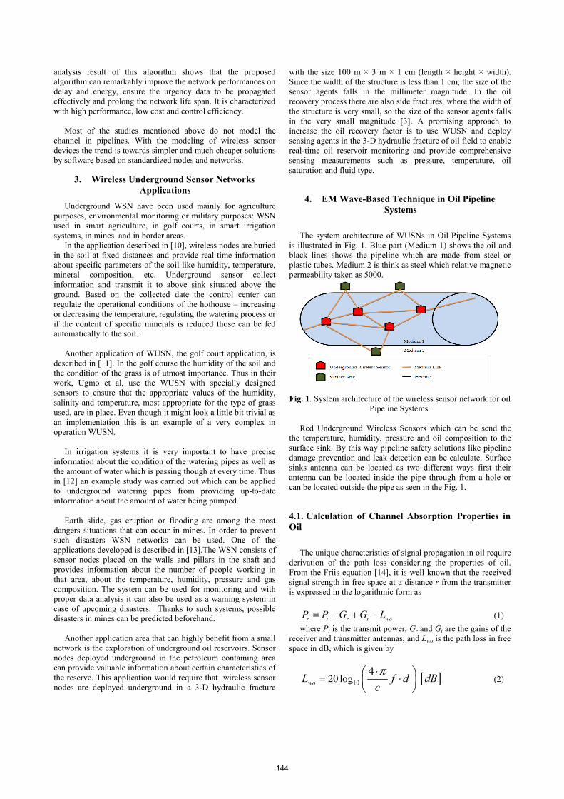
The Fig. 4 provides a graphical representation of the channel path at pipelines. The single-path channel comprises d1 and d2 (path d), while the two-path channel model comprises r1 - r3 and r2 - r4 (reflection from the oil-iron interface). The diagram in Fig. 4 is a simple block diagram including the envisaged hardware components (for clarity two nodes are shown), as well as the distances between the nodes considered in the theoretical derivations above. It should be reminded that one of the major requirements of the network considered (the general architecture as shown in Fig. 1) is to use the same type of nodes both for the underground and the aboveground with the addition that the underground nodes should be protected in a suitable way.
Fig. 4. Two-path channel model
In two-path oil model the reflection coefficients at the oil interfaces with iron have an contribution in the path loss under 4 m. Upon examining Fig. 5 in more detail it can be seen that in one-path oil model is nearly the same with two-path oil model after 4 m.
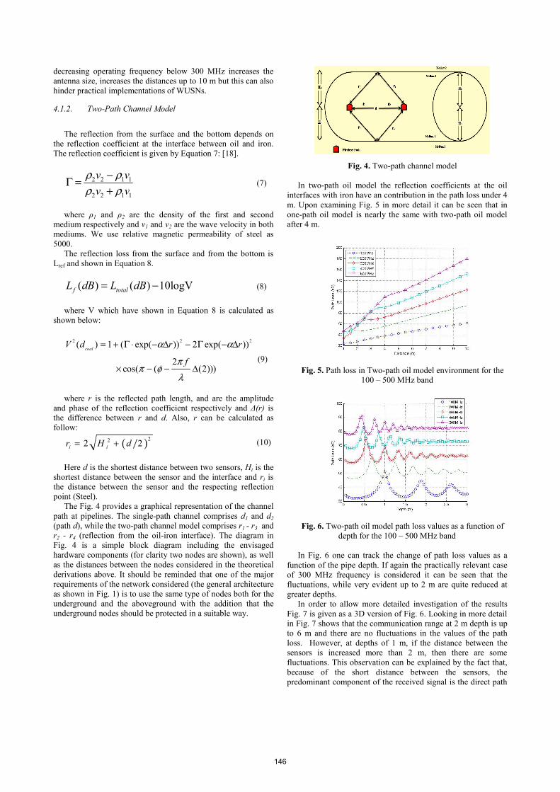
Fig. 5. Path loss in Two-path oil model environment for the
100 – 500 MHz band
Fig. 6. Two-path oil model path loss values as a function of depth for the 100 – 500 MHz band
In Fig. 6 one can track the change of path loss values as a
function of the pipe depth. If again the practically relevant case of 300 MHz frequency is considered it can be seen that the fluctuations, while very evident up to 2 m are quite reduced at greater depths.
In order to allow more detailed investigation of the results Fig. 7 is given as a 3D version of Fig. 6. Looking in more detail in Fig. 7 shows that the communication range at 2 m depth is up to 6 m and there are no fluctuations in the values of the path loss. However, at depths of 1 m, if the distance between the sensors is increased more than 2 m, then there are some fluctuations. This observation can be explained by the fact that, because of the short distance between the sensors, the predominant component of the received signal is the direct path
146
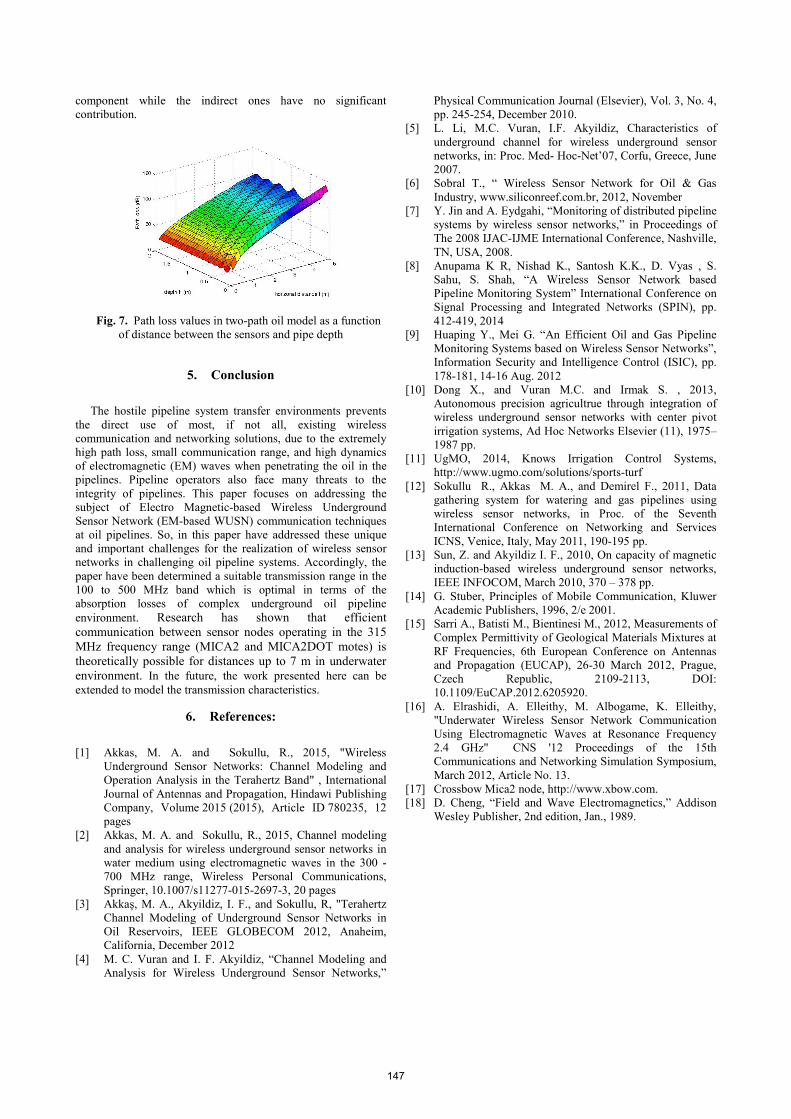
component while the indirect ones have no significant contribution.
Fig. 7. Path loss values in two-path oil model as a function of distance between the sensors and pipe depth
5. Conclusion
The hostile pipeline system transfer environments prevents the direct use of most, if not all, existing wireless communication and networking solutions, due to the extremely high path loss, small communication range, and high dynamics of electromagnetic (EM) waves when penetrating the oil in the pipelines. Pipeline operators also face many threats to the integrity of pipelines. This paper focuses on addressing the subject of Electro Magnetic-based Wireless Underground Sensor Network (EM-based WUSN) communication techniques at oil pipelines. So, in this paper have addressed these unique and important challenges for the realization of wireless sensor networks in challenging oil pipeline systems. Accordingly, the paper have been determined a suitable transmission range in the 100 to 500 MHz band which is optimal in terms of the absorption losses of complex underground oil pipeline environment. Research has shown that efficient communication between sensor nodes operating in the 315 MHz frequency range (MICA2 and MICA2DOT motes) is theoretically possible for distances up to 7 m in underwater environment. In the future, the work presented here can be extended to model the transmission characteristics.
6. References:
[1] Akkas, M. A. and Sokullu, R., 2015, "Wireless
Underground Sensor Networks: Channel Modeling and Operation Analysis in the Terahertz Band" , International Journal of Antennas and Propagation, Hindawi Publishing Company, Volume 2015 (2015), Article ID 780235, 12 pages
[2] Akkas, M. A. and Sokullu, R., 2015, Channel modeling and analysis for wireless underground sensor networks in water medium using electromagnetic waves in the 300 - 700 MHz range, Wireless Personal Communications, Springer, 10.1007/s11277-015-2697-3, 20 pages
[3] Akkaş, M. A., Akyildiz, I. F., and Sokullu, R, "Terahertz Channel Modeling of Underground Sensor Networks in Oil Reservoirs, IEEE GLOBECOM 2012, Anaheim, California, December 2012
[4] M. C. Vuran and I. F. Akyildiz, “Channel Modeling and Analysis for Wireless Underground Sensor Networks,”
Physical Communication Journal (Elsevier), Vol. 3, No. 4, pp. 245-254, December 2010.
[5] L. Li, M.C. Vuran, I.F. Akyildiz, Characteristics of underground channel for wireless underground sensor networks, in: Proc. Med- Hoc-Net’07, Corfu, Greece, June 2007.
[6] Sobral T., “ Wireless Sensor Network for Oil & Gas Industry, www.siliconreef.com.br, 2012, November
[7] Y. Jin and A. Eydgahi, “Monitoring of distributed pipeline systems by wireless sensor networks,” in Proceedings of The 2008 IJAC-IJME International Conference, Nashville, TN, USA, 2008.
[8] Anupama K R, Nishad K., Santosh K.K., D. Vyas , S. Sahu, S. Shah, “A Wireless Sensor Network based Pipeline Monitoring System” International Conference on Signal Processing and Integrated Networks (SPIN), pp. 412-419, 2014
[9] Huaping Y., Mei G. “An Efficient Oil and Gas Pipeline Monitoring Systems based on Wireless Sensor Networks”, Information Security and Intelligence Control (ISIC), pp. 178-181, 14-16 Aug. 2012
[10] Dong X., and Vuran M.C. and Irmak S. , 2013, Autonomous precision agricultrue through integration of wireless underground sensor networks with center pivot irrigation systems, Ad Hoc Networks Elsevier (11), 1975–1987 pp.
[11] UgMO, 2014, Knows Irrigation Control Systems, http://www.ugmo.com/solutions/sports-turf
[12] Sokullu R., Akkas M. A., and Demirel F., 2011, Data gathering system for watering and gas pipelines using wireless sensor networks, in Proc. of the Seventh International Conference on Networking and Services ICNS, Venice, Italy, May 2011, 190-195 pp.
[13] Sun, Z. and Akyildiz I. F., 2010, On capacity of magnetic induction-based wireless underground sensor networks, IEEE INFOCOM, March 2010, 370 – 378 pp.
[14] G. Stuber, Principles of Mobile Communication, Kluwer Academic Publishers, 1996, 2/e 2001.
[15] Sarri A., Batisti M., Bientinesi M., 2012, Measurements of Complex Permittivity of Geological Materials Mixtures at RF Frequencies, 6th European Conference on Antennas and Propagation (EUCAP), 26-30 March 2012, Prague, Czech Republic, 2109-2113, DOI: 10.1109/EuCAP.2012.6205920.
[16] A. Elrashidi, A. Elleithy, M. Albogame, K. Elleithy, "Underwater Wireless Sensor Network Communication Using Electromagnetic Waves at Resonance Frequency 2.4 GHz" CNS '12 Proceedings of the 15th Communications and Networking Simulation Symposium, March 2012, Article No. 13.
[17] Crossbow Mica2 node, http://www.xbow.com. [18] D. Cheng, “Field and Wave Electromagnetics,” Addison
Wesley Publisher, 2nd edition, Jan., 1989.
147