wireline cables - emcable.com · slickline certificate of assessment ... all of our wireline cables...
TRANSCRIPT
WIRELINECABLES
Oil & GasGeneral Catalog
ABOUT DEACERO
SERVICE CENTER LOCATIONS
AUTHORIZED DISTRIBUTORS
CABLE MANUFACTURING INFORMATION
CABLE SPECIFICATIONS / SUMMARY TABLE
HOW TO READ A PRODUCT CODE
185 • 1DTK • HS
224 • 1XPL • HS
224 • 1XTL • HS
224 • 1ZPL • HS
224 • 1ZTL • HS
224 • 1ZETL • HS
224 • 1ZFTL • HS
224 • 1ZATK • S75
224 • 1ZATK • S77
224 • 1ZATK • MP35
258 • 1ZPL • HS
258 • 1ZFTL • HS
288 • 1ZPL • HS
288 • 1ZTL • HS
288 • 1ZETL • HS
288 • 1ZFTL • HS
288 • 1ZATL • HS
288 • 1ZATL • S75
288 • 1ZATL • S77
288 • 1ZATL • MP35
322 • 1ZPL • HS
322 • 1ZETL • HS
02
03
04
05
06
07
08
09
10
11
12
13
14
15
16
17
18
19
20
21
22
23
24
25
26
27
28
29
322 • 1ZFTL • HS
322 • 1ZATL • S75
322 • 1ZATL • S77
322 • 1ZATL • MP35
380 • 1ZPL • HS
380 • 1ZFTL • HS
380 • 1ZFTL • HSLR
425 • 1ZPL • HS
425 • 1ZFTL • HSLR
185 • 3STK • HS
380 • 7SPK • HS
380 • 7STK • HS
384 • 3DPK • HS
384 • 3DTK • HS
426 • 7SPK • HS
426 • 7SFTK • HS
464 • 7RPK
464 • 7RFTK
474 • 7SPK • HS
474 • 7SFTK • HS
484 • 7DFTK • HS
490 • 7DFTK • HS
CABLE TREATMENT AND CARE
SWABLINE
SLICKLINE
CERTIFICATE OF ASSESSMENT
WARRANTY
30
31
32
33
34
35
36
37
38
39
40
41
42
43
44
45
46
47
48
49
50
51
52
53
55
56
57

02
AboutDeacero
Deacero, one of the largest steel wire manufacturers in North America, presents this electromechanical cable product catalog for the petroleum exploration and production industry. Deacero is a company with deep resources and a strong commitment to serve you with products and solutions that meet your electrome-chanical cable needs.
QUALITYAll employees of Deacero are dedicated to provide the highest quality products in compliance with the electromechanical industry and with ISO-9001.
Deacero is a vertically integrated company with quality control standards throu-gh-out its entire supply chain; from steel scrap to finished goods.
KNOWLEDGEDeacero is a customer-oriented company with a knowledgeable technical sales staff and attentive customer service to give you product solutions on any need you have.
SERVICEWith distribution centers strategically located around the US, Deacero is ready to supply promptly and efficiently to US and international customers.
TECHNOLOGYDeacero serves the industry with cables to cover the unique demands of corrosive environments and high temperatures by using special copper alloys, high tempe-rature insulations and special anti-corrosive alloy armoring materials.
Deacero is a proprietary developer of advanced, eco-friendly metal recycling and manufacturing technology.
ALBERTA
CALIFORNIA
WYOMING
KANSAS
OHIOPENNSYLVANIA
OKLAHOMA
LOUISIANATEXAS
QUERÉTARO
0303
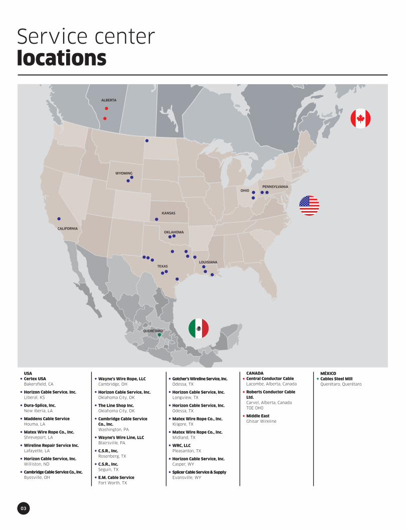
Service centerlocations
CANADACentral Conductor CableLacombe, Alberta, Canada Roberts Conductor CableLtd.Carvel, Alberta, CanadaT0E 0H0
Middle EastGhisar Wireline
MÉXICOCables Steel MillQuerétaro, Querétaro
USACertex USABakersfield, CA
Horizon Cable Service. Inc.Liberal, KS
Dura-Splice, Inc.New Iberia, LA
Maddens Cable ServiceHouma, LA
Matex Wire Rope Co., Inc.Shreveport, LA Wireline Repair Service Inc.Lafayette, LA
Horizon Cable Service, Inc.Williston, ND Cambridge Cable Service Co., Inc.Byesville, OH
Wayne’s Wire Rope, LLCCambridge, OH
Horizon Cable Service, Inc.Oklahoma City, OK The Line Shop Inc.Oklahoma City, OK
Cambridge Cable ServiceCo., Inc.Washington, PA
Wayne's Wire Line, LLCBlairsville, PA C.S.R., Inc.Rosenberg, TX C.S.R., Inc.Seguin, TX E.M. Cable ServiceFort Worth, TX
Gotcher’s Wireline Service, Inc.Odessa, TX Horizon Cable Service, Inc.Longview, TX
Horizon Cable Service, Inc.Odessa, TX
Matex Wire Rope Co., Inc.Kilgore, TX Matex Wire Rope Co., Inc.Midland, TX WRC, LLCPleasanton, TX Horizon Cable Service, Inc.Casper, WY Splicer Cable Service & SupplyEvansville, WY
Authorizeddistributors
CALIFORNIACertex USA3506 Gilmore Ave.Bakersfield, CA 93308Phone: (661) 327-3016Contact: Mike VasquezEmail: [email protected] KANSASHorizon Cable Service. Inc.623 Industrial Ave.Liberal, KS 67901Phone: (620) 309-8091Contact: Robert GranoEmail:[email protected] LOUSIANADura-Splice, Inc.3912 3rd St.New Iberia, LA 70560Phone: (337) 367-8840Contact: James NaquinEmail: [email protected] Maddens Cable Service146 Clendenning Rd.Houma, LA 70363Phone: (985) 637-9418Contact: Jerry MaddenEmail: [email protected] Matex Wire Rope Co., Inc.467 Montgomery St.Shreveport, LA 71107Phone: (903) 984-9691Contact: Mike MattewsEmail: [email protected] Wireline Repair Service Inc.102 Exposition DriveLafayette, LA 70508Phone: (337) 837-9330Contact: Brian DoironEmail: [email protected]
NORTH DAKOTAHorizon Cable Service, Inc.6115 16th Avenue WestWilliston, ND 58801Phone: (701) 774-1091Contact: Nathan BlackEmail: [email protected] OHIOCambridge Cable Service Co., Inc.58945 Country Club Rd.Byesville, OH 43723Phone: (740) 680-8532Contact: Kevin DeasonEmail: [email protected]
Wayne’s Wire Rope, LLC428 South 11 St.Cambridge, OH 43725Phone: (740) 255-5850Contact: Wayne StevensEmail:[email protected] OKLAHOMAHorizon Cable Service, Inc.45 N. Cooley Dr.Oklahoma City, OK 73127Phone: (405) 789-7125Contact: Robert SampleEmail:[email protected] The Line Shop Inc.5700 Southwest 11th St.Oklahoma City, OK 73128Phone: (405) 942-8828Contact: Cullen FalgoutEmail: [email protected] PENNSYLVANIACambridge Cable Service Co., Inc.1148 Findley St.Washington, PA 15031Phone: (740) 680-8532Contact: Kevin DeasonEmail: [email protected]
Wayne's Wire Line, LLC2174 US 22 Highway WBlairsville, PA 15717Phone: (724) 459-5510Contact: Brent McManawayEmail: [email protected] TEXASC.S.R., Inc.1131 Blume RoadRosenberg, TX 77471Phone: (281) 342-4492Contact: Keith Nutt or Kent NuttEmail: [email protected] Email: [email protected] C.S.R., Inc.2200 Ilka SwitchSeguin, TX 78155Phone: (281) 342-4492Contact: Keith Nutt or Kent NuttEmail: [email protected] Email: [email protected] E.M. Cable Service1225 Barron WayFort Worth, TX 76140Contact: Jeremy BentleyPhone: (817) 293-3850Email: [email protected]
Gotcher’s Wireline Service, Inc.12115 County Road 128 WestOdessa, TX 79760Phone: (432) 563-3512Contact: Robert GotcherE-mail: [email protected] Horizon Cable Service, Inc.715 S. Eastman Rd.Longview, TX 75604Phone: (903) 234-1558Contact: Jeff TuckerEmail:[email protected]
Horizon Cable Service, Inc.12215 WCR 129Odessa, TX 79765Phone: (432) 563-3331Contact: Robert YoungEmail:[email protected] Matex Wire Rope Co., Inc.1215 Industrial BoulevardKilgore, TX 75662Phone: (903) 984-9691Contact: Mike MatthewsEmail: [email protected] Matex Wire Rope Co., Inc.10608 W. CR 150Midland, TX 79706Phone: (903) 984-9691Contact: Mike MatthewsEmail: [email protected] WRC, LLC2282 U.S. Hwy. 281 SouthPleasanton, TX 78064Phone: (830) 569-2700Contact: Randy Greenhill Email: [email protected] WYOMINGHorizon Cable Service, Inc.3070 North 6 Mile Rd.Casper, WY 82609Phone: (307) 472-9100Contact: Mike BoyleEmail:[email protected] Splicer Cable Service & Supply13667 East Highway 2026Evansville, WY 82604Phone: (307) 472-3318Contact: Adam McLaughlinE-mail: [email protected]
CANADACentral Conductor Cable3705 52nd Ave.Wolf Creek Industrial ParkLacombe, Alberta, Canada T4L 0B9Phone: (403) 782-2238Contact: Tom BuryniukE-mail:[email protected] Roberts Conductor Cable Ltd.RR 1Carvel, Alberta, Canada T0E 0H0Phone: (780) 892-2510Contact:: Cal and John RobertsE-mail: [email protected] Middle EastGhisar WirelinePO Box: 27354M/17 Mussafah, Abu Dhabi, UAEPhone: +971 2 554 0650Contact: Paul HamletEmail:[email protected]
MÉXICODEACERO Cables Steel MillAvenida Felipe Carillo Puerto# 301, Querétaro, QuerétaroCP 76130
04
05
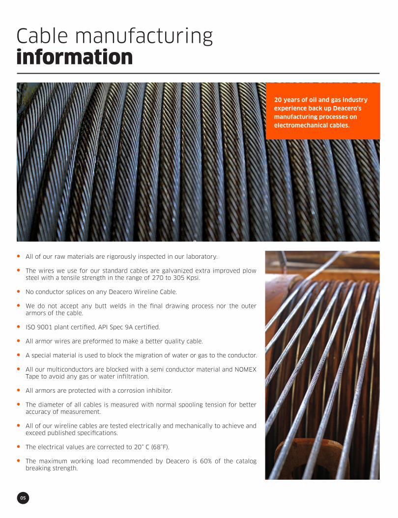
Cable manufacturinginformation
All of our raw materials are rigorously inspected in our laboratory.
The wires we use for our standard cables are galvanized extra improved plow steel with a tensile strength in the range of 270 to 305 Kpsi.
No conductor splices on any Deacero Wireline Cable.
We do not accept any butt welds in the final drawing process nor the outer armors of the cable.
ISO 9001 plant certified, API Spec 9A certified.
All armor wires are preformed to make a better quality cable.
A special material is used to block the migration of water or gas to the conductor.
All our multiconductors are blocked with a semi conductor material and NOMEX Tape to avoid any gas or water infiltration.
All armors are protected with a corrosion inhibitor.
The diameter of all cables is measured with normal spooling tension for better accuracy of measurement.
All of our wireline cables are tested electrically and mechanically to achieve and exceed published specifications.
The electrical values are corrected to 20° C (68°F).
The maximum working load recommended by Deacero is 60% of the catalog breaking strength.
20 years of oil and gas industryexperience back up Deacero’smanufacturing processes onelectromechanical cables.

06
Cable specificationsSummary table
185 l 1DTK l HS
224 l 1XPL l HS
224 l 1XTL l HS
224 l 1ZPL l HS
224 l 1ZTL l HS
224 l 1ZETL l HS
224 l 1ZFTL l HS
224 l 1ZATK l S75
224 l 1ZATK l S77
224 l 1ZATK l MP35
258 l 1ZPL l HS
258 l 1ZFTL l HS
288 l 1ZPL l HS
288 l 1ZTL l HS
288 l 1ZETL l HS
288 l 1ZFTL l HS
288 l 1ZATL l HS
288 l 1ZATL l S75
288 l 1ZATL l S77
288 l 1ZATL l MP35
322 l 1ZPL l HS
322 l 1ZETL l HS
322 l 1ZFTL l HS
322 l 1ZATL l S75
322 l 1ZATL l S77
322 l 1ZATL l MP35
380 l 1ZPL l HS
380 l 1ZFTL l HS
380 l 1ZFTL l HSLR
425 l 1ZPL l HS
425 l 1ZFTL l HSLR
185 l 3STK l HS
380 l 7SPK l HS
380 l 7STK l HS
384 l 3DPK l HS
384 l 3DTK l HS
426 l 7SPK l HS
426 l 7SFTK l HS
464 l 7RPK
464 l 7RFTK
474 l 7SPK l HS
474 l 7SFTK l HS
484 l 7DFTK l HS
490 l 7DFTK l HS
Cable Type
3/16
7/32
7/32
7/32
7/32
7/32
7/32
7/32
7/32
7/32
1/4
1/4
9/32
9/32
9/32
9/32
9/32
9/32
9/32
9/32
5/16
5/16
5/16
5/16
5/16
5/16
3/8
3/8
3/8
7/16
7/16
3/16
3/8
3/8
3/8
3/8
7/16
7/16
15/32
15/32
SLAMMER
SLAMMER
SLAMMER
SLAMMER
Size
(”)
0.185
0.224
0.224
0.224
0.224
0.224
0.224
0.224
0.224
0.224
0.258
0.258
0.288
0.288
0.288
0.288
0.288
0.288
0.288
0.288
0.322
0.322
0.322
0.322
0.322
0.322
0.380
0.380
0.380
0.425
0.425
0.186
0.378
0.378
0.384
0.384
0.426
0.426
0.464
0.464
0.474
0.474
0.484
0.490
Diameter
(”)
4,300
6,100
6,100
6,100
6,100
6,100
6,100
5,000
5,200
5,400
8,200
8,200
10,400
10,400
10,400
10,400
10,400
8,600
8,900
9,400
12,400
12,400
12,400
10,400
10,600
11,200
17,500
17,500
17,500
22,000
22,000
3,800
15,500
15,500
16,500
16,000
20,000
20,000
20,000
20,000
24,500
24,500
27,600
26,000
BreakingStrength
(lbf)
66
94
96
94
95
97
97
96
96
100
120
125
154
158
160
160
160
167
167
174
188
195
195
206
206
206
259
269
269
325
335
65
254
261
267
267
310
322
321
341
377
392
409
405
Weight
(lbs)
12/15
15/15
15/15
12/18
12/18
12/18
12/18
12/18
12/18
12/18
12/18
12/18
12/18
12/18
12/18
12/18
12/18
12/18
12/18
12/18
12/18
12/18
12/18
12/18
12/18
12/18
12/18
12/18
12/18
12/18
12/18
18/18
18/18
18/18
16/20
16/20
18/18
18/18
24/24
24/24
18/18
18/18
16/18
20/20
ArmorWiresIn/Out
1,000
1,200
1,200
1,200
1,200
1,200
1,200
1,200
1,200
1,200
1,200
1,200
1,500
1,500
1,500
1,500
1,500
1,500
1,500
1,500
1,500
1,500
1,500
1,500
1,500
1,500
1,500
1,500
1,500
1,500
1,500
1,000
1,000
1,000
1,200
1,200
1,000
1,000
1,200
1,200
1,100
1,100
1,100
1,200
Max.Volt.
137/207
137/294
137/294
221/221
221/221
221/221
221/221
190/190
195/195
210/210
294/294
294/294
375/375
375/375
375/375
375/375
375/375
315/315
320/320
347/347
451/451
451/451
451/451
380/380
387/387
395/395
625/625
625/625
625/625
773/773
773/773
80/150
320/625
320/625
431/534
431/534
415/780
415/780
348/556
348/556
502/936
502/936
650/1071
485/870
(lbs)
WireStrengthIn/Out
3.10
2.20
2.20
2.20
2.20
2.20
2.20
2.30
2.20
2.10
1.70
1.70
1.30
1.30
1.30
1.30
1.30
1.30
1.30
1.20
1.10
1.10
1.10
1.10
1.10
1.00
1.00
1.00
1.00
0.70
0.70
3.60
1.00
1.00
1.00
1.00
0.70
0.70
0.77
0.77
0.61
0.61
0.61
0.60
(ft/kft/klb)
StretchCoefficient
9.8
4.1
4.1
4.1
4.1
4.1
4.1
6.5
6.5
6.5
4.1
4.1
2.8
2.8
2.8
2.8
2.8
2.9
2.9
2.9
2.8
2.8
2.8
3.1
3.1
3.1
2.8
2.8
2.3
2.8
2.1
22.0
9.8
9.8
6.4
6.4
9.8
9.8
9.8
9.8
9.8
9.8
9.8
9.8
(Ohms/Kft)
ConductorResistance
55
62
69
62
69
62
62
45
45
45
52
53
58
64
58
58
58
58
58
58
49
48
48
48
48
48
40
40
46
36
44
52
72
79
54
60
58
58
41
42
48
48
50
48
(pf/ft)
Cap
500
300
500
300
500
600
500
500
500
500
300
500
300
500
600
500
500
500
500
500
300
600
500
500
500
500
300
500
500
300
500
500
300
500
300
500
300
500
300
500
300
500
500
500
(Deg F)
Max.Temp.
12
14
14
13
13
13
13
13
13
13
14.3
14.3
16
16
16
16
16
16
16
16
18
18
18
18
18
18
21
21
21
24
24
12
21
21
20
20
24
24
20
20
27
27
27
25
(”)
Min. SheaveDiameter
MONOCONDUCTOR
MULTICONDUCTOR
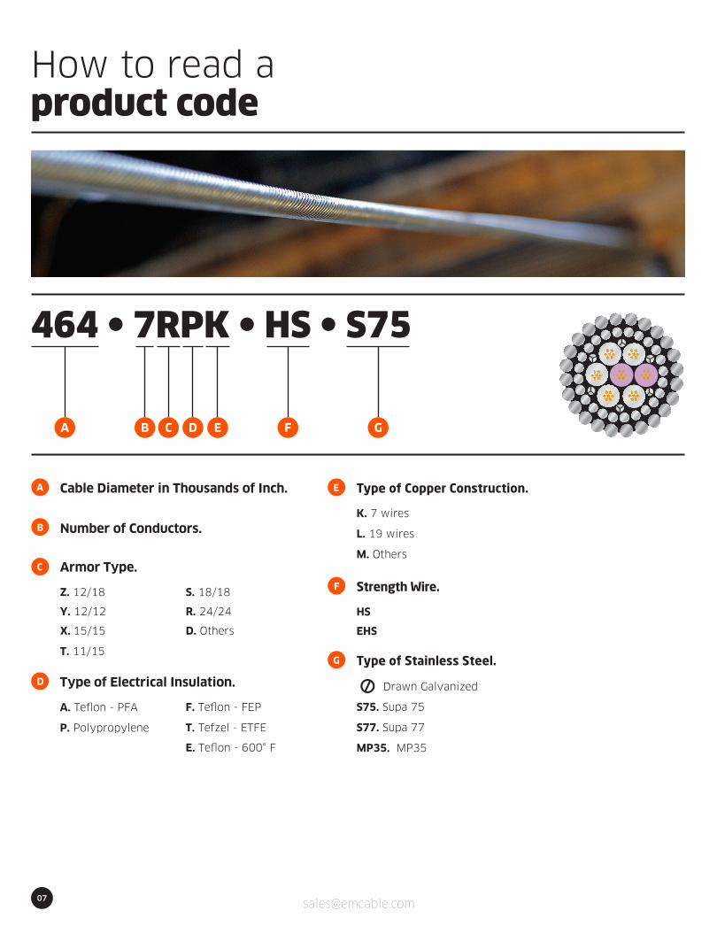
464 l 7RPK l HS l S75
A
B
C
Cable Diameter in Thousands of Inch.
Number of Conductors.
Armor Type.
Z. 12/18
Y. 12/12
X. 15/15
T. 11/15
S. 18/18
R. 24/24
D. Others
F
E
Strength Wire.
HS
EHS
D Type of Electrical Insulation.
A. Teflon - PFA
P. Polypropylene
F. Teflon - FEP
T. Tefzel - ETFE
E. Teflon - 600° F
Type of Copper Construction.
K. 7 wires
L. 19 wires
M. Others
G Type of Stainless Steel.
S75. Supa 75
S77. Supa 77
Drawn Galvanized
MP35. MP35
07
How to read aproduct code
A B C D E F G

08
3/16” 4.70 mmMONOCONDUCTOR
CONDUCTOR:INSULATION:ARMOR:
Copper, Water Blocked.ETFE.Galvanized high strength steel (GEIPS)preformed and coated with a corrosionpreventative lubricant compound.
Special Sealant is applied between armor layers.
185 l 1DTK l HS
Construction Characteristics
Conductor – # 20 AWG, 7 x 0.0128”
Wall Thickness:
Insulation Conductors - OD:
Armor – Inner: 12 wires 0.0243”
Armor – Outer: 15 wires 0.0300”
English
0.038”
0.023”
0.084”
0.125”
0.185”
Metric
0.965 mm
0.584 mm
2.134 mm
3.175 mm
4.699 mm
dia.
dia.
dia.
dia.
Electrical Characteristics
Voltage Rating
D.C. Conductor Resistance at 68º F (20º C) (Maximum)
D.C. Armor Resistance at 68º F (20º C) (Maximum)
Capacitance Conductor to Armor (Maximum)
Insulation Resistance (Minimum) @ 500 VDC
English
1,000 VDC
9.8 Ω/kft
6.2 Ω/kft
55 pF/ft
50,000 MΩ/kft
Metric
1,000 VDC
32.2 Ω/km
20.3 Ω/km
180 pF/m
15,000 MΩ/km
dia.
0.185” 4.70 mm
Mechanical Characteristics
Weight in Air
Weight in Water
Minimum Breaking Strength, Ends Fixed
Minimum Wire Break Strength (In/Out)
Maximum Working Load
Temperature Rating (Maximum)
Suggested Minimum Sheave
Stretch Coefficient (Nominal)
Outside Diameter
English
66 lb/kft
56 lb/kft
4,300 lbf
137/207 lbf
2,365 lbf
500º F
12”
3.1 ft /kft/klb
+ 0.004”
- 0.002”
Metric
98 kg/km
83 kg/km
19.13 kN
609/921 N
10.52 kN
260º C
305 mm
3.48 m/km/5kN
+ 0.102 mm
- 0.051 mm

09
7/32” 5.69 mmMONOCONDUCTOR
CONDUCTOR:INSULATION:ARMOR:
Copper, Water Blocked.Polypropylene.Galvanized high strength steel (GEIPS)preformed and coated with a corrosionpreventative lubricant compound.
Special Sealant is applied between armor layers.
224 l 1XPL l HS
Construction Characteristics
Conductor – # 16 AWG, 19 x 0.0119”
Wall Thickness:
Insulation - OD:
Armor – Inner: 15 wires 0.0243”
Armor – Outer: 15 wires 0.0358”
English
0.059”
0.0245”
0.108”
0.152”
0.224”
Metric
1.499 mm
0.6223 mm
2.743 mm
3.861 mm
5.690 mm
dia.
dia.
dia.
dia.
Electrical Characteristics
Voltage Rating
D.C. Conductor Resistance at 68º F (20º C) (Maximum)
D.C. Armor Resistance at 68º F (20º C) (Maximum)
Capacitance Conductor to Armor (Maximum)
Insulation Resistance (Minimum) @ 500 VDC
English
1,200 VDC
4.1 Ω/kft
4.3 Ω/kft
62 pF/ft
50,000 MΩ/kft
Metric
1,200 VDC
13.5 Ω/km
14.1 Ω/km
203 pF/m
15,000 MΩ/km
dia.
0.224” 5.69 mm
Mechanical Characteristics
Weight in Air
Weight in Water
Minimum Breaking Strength, Ends Fixed
Minimum Wire Break Strength (In/Out)
Maximum Working Load
Temperature Rating (Maximum)
Suggested Minimum Sheave
Stretch Coefficient (Nominal)
Outside Diameter
English
94 lb/kft
79 lb/kft
6,100 lbf
137/294 lbf
3,355 lbf
300º F
14”
2.20 ft /kft/klb
+ 0.005”
- 0.002”
Metric
140 kg/km
118 kg/km
27.13 kN
609/1308 N
14.92 kN
149º C
356 mm
2.47 m/km/5kN
+ 0.127 mm
- 0.051 mm

10
7/32” 5.69 mmMONOCONDUCTOR
CONDUCTOR:INSULATION:ARMOR:
Copper, Water Blocked.ETFE.Galvanized high strength steel (GEIPS)preformed and coated with a corrosionpreventative lubricant compound.
Special Sealant is applied between armor layers.
224 l 1XTL l HS
Construction Characteristics
Conductor – # 16 AWG, 19 x 0.0119”
Wall Thickness:
Insulation - OD:
Armor – Inner: 15 wires 0.0243”
Armor – Outer: 15 wires 0.0358”
English
0.059”
0.0245”
0.108”
0.152”
0.224”
Metric
1.499 mm
0.6223 mm
2.743 mm
3.861 mm
5.690 mm
dia.
dia.
dia.
dia.
Electrical Characteristics
Voltage Rating
D.C. Conductor Resistance at 68º F (20º C) (Maximum)
D.C. Armor Resistance at 68º F (20º C) (Maximum)
Capacitance Conductor to Armor (Maximum)
Insulation Resistance (Minimum) @ 500 VDC
English
1,200 VDC
4.1 Ω/kft
4.3 Ω/kft
69 pF/ft
50,000 MΩ/kft
Metric
1,200 VDC
13.5 Ω/km
14.1 Ω/km
226 pF/m
15,000 MΩ/km
dia.
0.224” 5.69 mm
Mechanical Characteristics
Weight in Air
Weight in Water
Minimum Breaking Strength, Ends Fixed
Minimum Wire Break Strength (In/Out)
Maximum Working Load
Temperature Rating (Maximum)
Suggested Minimum Sheave
Stretch Coefficient (Nominal)
Outside Diameter
English
96 lb/kft
82 lb/kft
6,100 lbf
137/294 lbf
3,355 lbf
500º F
14”
2.20 ft /kft/klb
+ 0.005”
- 0.002”
Metric
143 kg/km
122 kg/km
27.13 kN
609/1308 N
14.92 kN
260º C
356 mm
2.47 m/km/5kN
+ 0.127 mm
- 0.051 mm

11
7/32” 5.69 mmMONOCONDUCTOR
CONDUCTOR:INSULATION:ARMOR:
Copper, Water Blocked.Polypropylene.Galvanized high strength steel (GEIPS)preformed and coated with a corrosionpreventative lubricant compound.
Special Sealant is applied between armor layers.
224 l 1ZPL l HS
Construction Characteristics
Conductor – # 16 AWG, 19 x 0.0119”
Wall Thickness:
Insulation - OD:
Armor – Inner: 12 wires 0.031”
Armor – Outer: 18 wires 0.031”
English
0.059”
0.0245”
0.108”
0.162”
0.224”
Metric
1.499 mm
0.6223 mm
2.743 mm
4.115 mm
5.690 mm
dia.
dia.
dia.
dia.
Electrical Characteristics
Voltage Rating
D.C. Conductor Resistance at 68º F (20º C) (Maximum)
D.C. Armor Resistance at 68º F (20º C) (Maximum)
Capacitance Conductor to Armor (Maximum)
Insulation Resistance (Minimum) @ 500 VDC
English
1,200 VDC
4.1 Ω/kft
4.3 Ω/kft
62 pF/ft
50,000 MΩ/kft
Metric
1,200 VDC
13.5 Ω/km
14.1 Ω/km
203 pF/m
15,000 MΩ/km
dia.
0.224” 5.69 mm
Mechanical Characteristics
Weight in Air
Weight in Water
Minimum Breaking Strength, Ends Fixed
Minimum Wire Break Strength (In/Out)
Maximum Working Load
Temperature Rating (Maximum)
Suggested Minimum Sheave
Stretch Coefficient (Nominal)
Outside Diameter
English
94 lb/kft
79 lb/kft
6,100 lbf
221 /221 lbf
3,355 lbf
300º F
13”
2.2 ft /kft/klb
+ 0.005”
- 0.002”
Metric
140 kg/km
118 kg/km
27.13 kN
983/983 N
14.92 kN
149º C
330 mm
2.5 m/km/5kN
+ 0.127 mm
- 0.051 mm

12
7/32” 5.69 mmMONOCONDUCTOR
CONDUCTOR:INSULATION:ARMOR:
Copper, Water Blocked.ETFE.Galvanized high strength steel (GEIPS)preformed and coated with a corrosionpreventative lubricant compound.
Special Sealant is applied between armor layers.
224 l 1ZTL l HS
Construction Characteristics
Conductor – # 16 AWG, 19 x 0.0119”
Wall Thickness:
Insulation - OD:
Armor – Inner: 12 wires 0.031”
Armor – Outer: 18 wires 0.031”
English
0.059”
0.0245”
0.108”
0.162”
0.224”
Metric
1.499 mm
0.6223 mm
2.743 mm
4.115 mm
5.690 mm
dia.
dia.
dia.
dia.
Electrical Characteristics
Voltage Rating
D.C. Conductor Resistance at 68º F (20º C) (Maximum)
D.C. Armor Resistance at 68º F (20º C) (Maximum)
Capacitance Conductor to Armor (Maximum)
Insulation Resistance (Minimum) @ 500 VDC
English
1,200 VDC
4.1 Ω/kft
4.3 Ω/kft
69 pF/ft
50,000 MΩ/kft
Metric
1,200 VDC
13.5 Ω/km
14.1 Ω/km
226 pF/m
15,000 MΩ/km
dia.
0.224” 5.69 mm
Mechanical Characteristics
Weight in Air
Weight in Water
Minimum Breaking Strength, Ends Fixed
Minimum Wire Break Strength (In/Out)
Maximum Working Load
Temperature Rating (Maximum)
Suggested Minimum Sheave
Stretch Coefficient (Nominal)
Outside Diameter
English
95 lb/kft
81 lb/kft
6,100 lbf
221 /221 lbf
3,355 lbf
500º F
13”
2.2 ft /kft/klb
+ 0.005”
- 0.002”
Metric
142 kg/km
121 kg/km
27.13 kN
983/983 N
14.92 kN
260º C
330 mm
2.5 m/km/5kN
+ 0.127 mm
- 0.051 mm

13
HIGHEST TEMPERATURE (600°F) | 7/32” 5.69 mmMONOCONDUCTOR
CONDUCTOR:INSULATION:ARMOR:
Copper, Water Blocked.ECCTREME.Galvanized high strength steel (GEIPS)preformed and coated with a corrosionpreventative lubricant compound.
Special Sealant is applied between armor layers.
224 l 1ZETL l HS
Construction Characteristics
Conductor – # 16 AWG, 19 x 0.0119”
Wall Thickness:
Insulation - OD:
Armor – Inner: 12 wires 0.031”
Armor – Outer: 18 wires 0.031”
English
0.059”
0.0245”
0.108”
0.162”
0.224”
Metric
1.499 mm
0.6223 mm
2.743 mm
4.115 mm
5.690 mm
dia.
dia.
dia.
dia.
Electrical Characteristics
Voltage Rating
D.C. Conductor Resistance at 68º F (20º C) (Maximum)
D.C. Armor Resistance at 68º F (20º C) (Maximum)
Capacitance Conductor to Armor (Maximum)
Insulation Resistance (Minimum) @ 500 VDC
English
1,200 VDC
4.1 Ω/kft
4.3 Ω/kft
62 pF/ft
50,000 MΩ/kft
Metric
1,200 VDC
13.5 Ω/km
14.1 Ω/km
203 pF/m
15,000 MΩ/km
dia.
0.224” 5.69 mm
Mechanical Characteristics
Weight in Air
Weight in Water
Minimum Breaking Strength, Ends Fixed
Minimum Wire Break Strength (In/Out)
Maximum Working Load
Temperature Rating (Maximum)
Suggested Minimum Sheave
Stretch Coefficient (Nominal)
Outside Diameter
English
97 lb/kft
82 lb/kft
6,100 lbf
221/221 lbf
3,355 lbf
600º F
13”
2.2 ft /kft/klb
+ 0.005”
- 0.002”
Metric
144 kg/km
122 kg/km
27.13 kN
983/983 N
14.92 kN
316º C
330 mm
2.5 m/km/5kN
+ 0.127 mm
- 0.051 mm
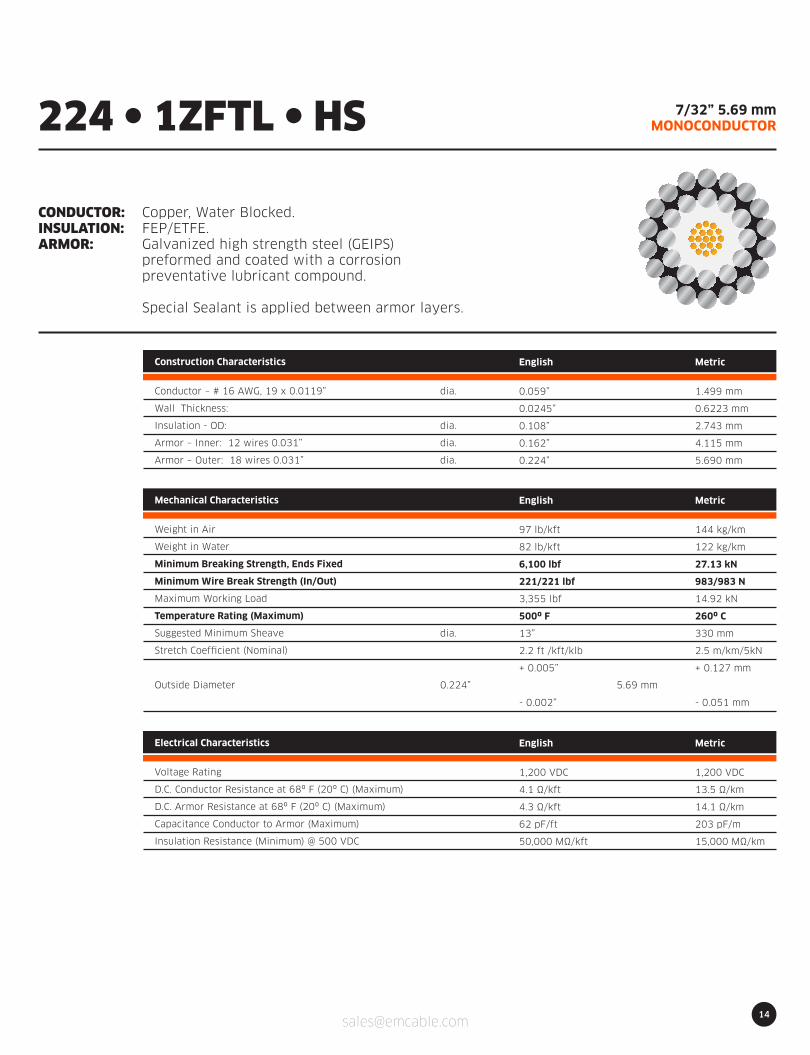
14
7/32” 5.69 mmMONOCONDUCTOR
CONDUCTOR:INSULATION:ARMOR:
Copper, Water Blocked.FEP/ETFE.Galvanized high strength steel (GEIPS)preformed and coated with a corrosionpreventative lubricant compound.
Special Sealant is applied between armor layers.
224 l 1ZFTL l HS
Construction Characteristics
Conductor – # 16 AWG, 19 x 0.0119”
Wall Thickness:
Insulation - OD:
Armor – Inner: 12 wires 0.031”
Armor – Outer: 18 wires 0.031”
English
0.059”
0.0245”
0.108”
0.162”
0.224”
Metric
1.499 mm
0.6223 mm
2.743 mm
4.115 mm
5.690 mm
dia.
dia.
dia.
dia.
Electrical Characteristics
Voltage Rating
D.C. Conductor Resistance at 68º F (20º C) (Maximum)
D.C. Armor Resistance at 68º F (20º C) (Maximum)
Capacitance Conductor to Armor (Maximum)
Insulation Resistance (Minimum) @ 500 VDC
English
1,200 VDC
4.1 Ω/kft
4.3 Ω/kft
62 pF/ft
50,000 MΩ/kft
Metric
1,200 VDC
13.5 Ω/km
14.1 Ω/km
203 pF/m
15,000 MΩ/km
dia.
0.224” 5.69 mm
Mechanical Characteristics
Weight in Air
Weight in Water
Minimum Breaking Strength, Ends Fixed
Minimum Wire Break Strength (In/Out)
Maximum Working Load
Temperature Rating (Maximum)
Suggested Minimum Sheave
Stretch Coefficient (Nominal)
Outside Diameter
English
97 lb/kft
82 lb/kft
6,100 lbf
221/221 lbf
3,355 lbf
500º F
13”
2.2 ft /kft/klb
+ 0.005”
- 0.002”
Metric
144 kg/km
122 kg/km
27.13 kN
983/983 N
14.92 kN
260º C
330 mm
2.5 m/km/5kN
+ 0.127 mm
- 0.051 mm
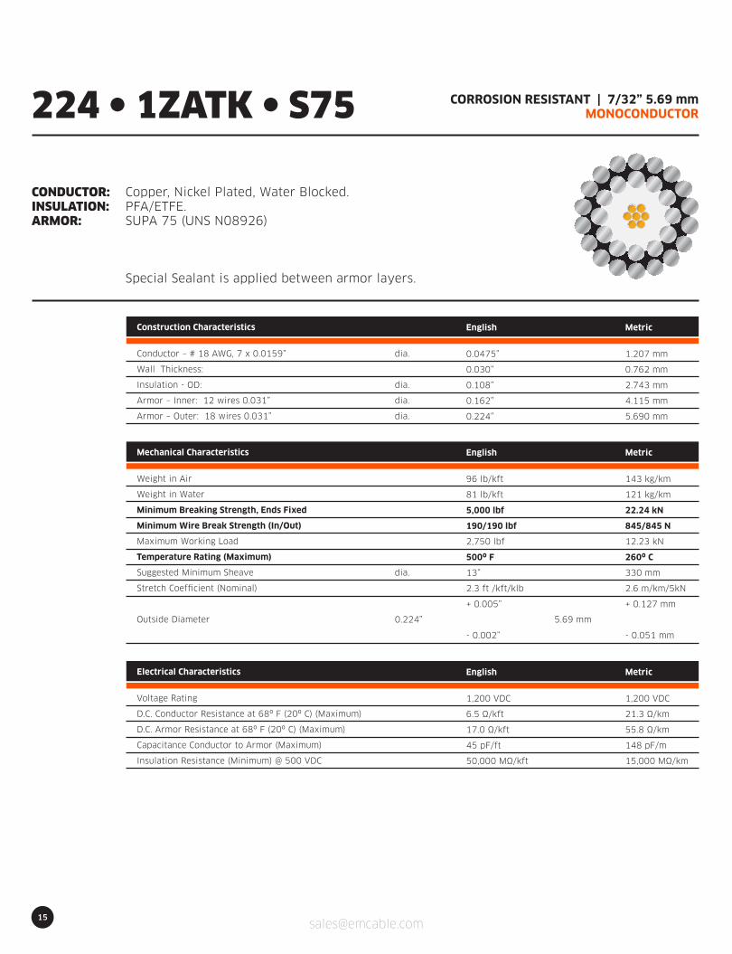
15
CORROSION RESISTANT | 7/32” 5.69 mmMONOCONDUCTOR
CONDUCTOR:INSULATION:ARMOR:
Copper, Nickel Plated, Water Blocked.PFA/ETFE.SUPA 75 (UNS N08926)
Special Sealant is applied between armor layers.
224 l 1ZATK l S75
Construction Characteristics
Conductor – # 18 AWG, 7 x 0.0159”
Wall Thickness:
Insulation - OD:
Armor – Inner: 12 wires 0.031”
Armor – Outer: 18 wires 0.031”
English
0.0475”
0.030”
0.108”
0.162”
0.224”
Metric
1.207 mm
0.762 mm
2.743 mm
4.115 mm
5.690 mm
dia.
dia.
dia.
dia.
Electrical Characteristics
Voltage Rating
D.C. Conductor Resistance at 68º F (20º C) (Maximum)
D.C. Armor Resistance at 68º F (20º C) (Maximum)
Capacitance Conductor to Armor (Maximum)
Insulation Resistance (Minimum) @ 500 VDC
English
1,200 VDC
6.5 Ω/kft
17.0 Ω/kft
45 pF/ft
50,000 MΩ/kft
Metric
1,200 VDC
21.3 Ω/km
55.8 Ω/km
148 pF/m
15,000 MΩ/km
dia.
0.224” 5.69 mm
Mechanical Characteristics
Weight in Air
Weight in Water
Minimum Breaking Strength, Ends Fixed
Minimum Wire Break Strength (In/Out)
Maximum Working Load
Temperature Rating (Maximum)
Suggested Minimum Sheave
Stretch Coefficient (Nominal)
Outside Diameter
English
96 lb/kft
81 lb/kft
5,000 lbf
190/190 lbf
2,750 lbf
500º F
13”
2.3 ft /kft/klb
+ 0.005”
- 0.002”
Metric
143 kg/km
121 kg/km
22.24 kN
845/845 N
12.23 kN
260º C
330 mm
2.6 m/km/5kN
+ 0.127 mm
- 0.051 mm
16
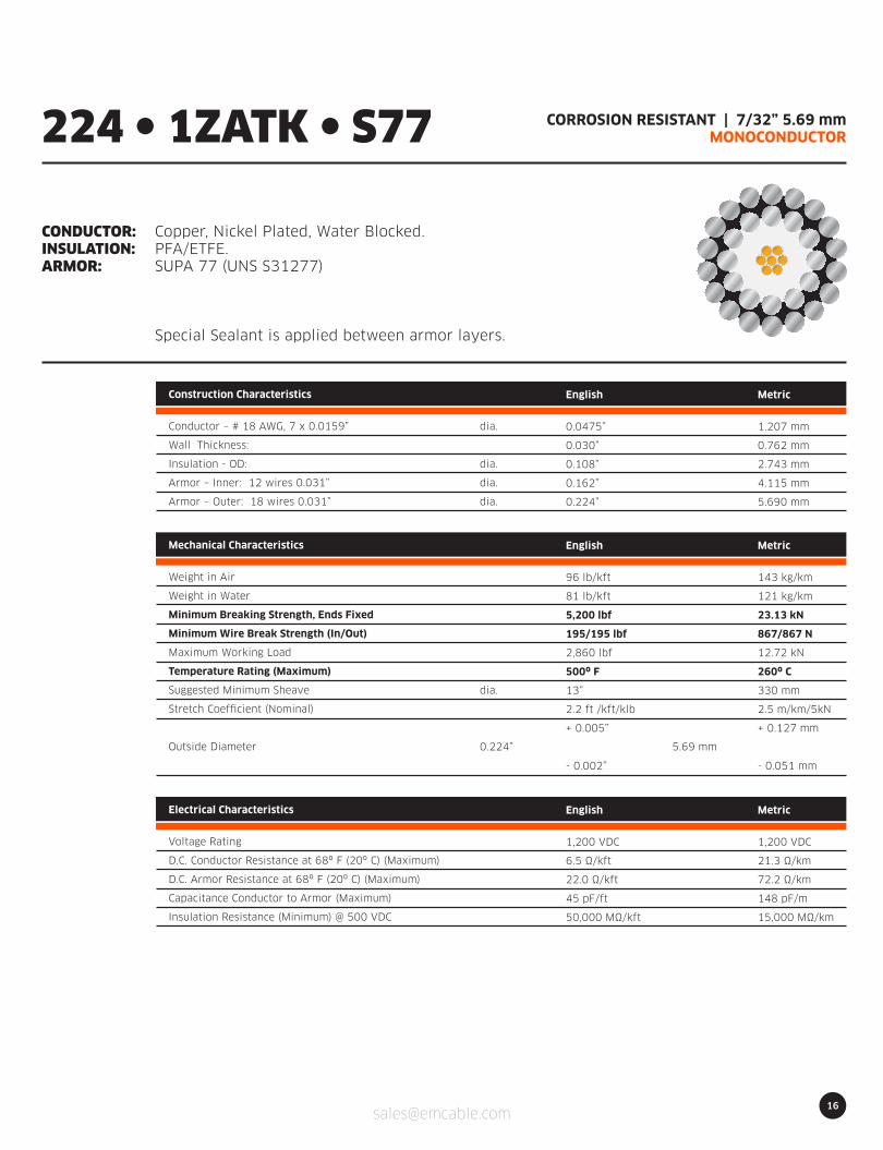
CORROSION RESISTANT | 7/32” 5.69 mmMONOCONDUCTOR
CONDUCTOR:INSULATION:ARMOR:
Copper, Nickel Plated, Water Blocked.PFA/ETFE.SUPA 77 (UNS S31277)
Special Sealant is applied between armor layers.
224 l 1ZATK l S77
Construction Characteristics
Conductor – # 18 AWG, 7 x 0.0159”
Wall Thickness:
Insulation - OD:
Armor – Inner: 12 wires 0.031”
Armor – Outer: 18 wires 0.031”
English
0.0475”
0.030”
0.108”
0.162”
0.224”
Metric
1.207 mm
0.762 mm
2.743 mm
4.115 mm
5.690 mm
dia.
dia.
dia.
dia.
Electrical Characteristics
Voltage Rating
D.C. Conductor Resistance at 68º F (20º C) (Maximum)
D.C. Armor Resistance at 68º F (20º C) (Maximum)
Capacitance Conductor to Armor (Maximum)
Insulation Resistance (Minimum) @ 500 VDC
English
1,200 VDC
6.5 Ω/kft
22.0 Ω/kft
45 pF/ft
50,000 MΩ/kft
Metric
1,200 VDC
21.3 Ω/km
72.2 Ω/km
148 pF/m
15,000 MΩ/km
dia.
0.224” 5.69 mm
Mechanical Characteristics
Weight in Air
Weight in Water
Minimum Breaking Strength, Ends Fixed
Minimum Wire Break Strength (In/Out)
Maximum Working Load
Temperature Rating (Maximum)
Suggested Minimum Sheave
Stretch Coefficient (Nominal)
Outside Diameter
English
96 lb/kft
81 lb/kft
5,200 lbf
195/195 lbf
2,860 lbf
500º F
13”
2.2 ft /kft/klb
+ 0.005”
- 0.002”
Metric
143 kg/km
121 kg/km
23.13 kN
867/867 N
12.72 kN
260º C
330 mm
2.5 m/km/5kN
+ 0.127 mm
- 0.051 mm
17
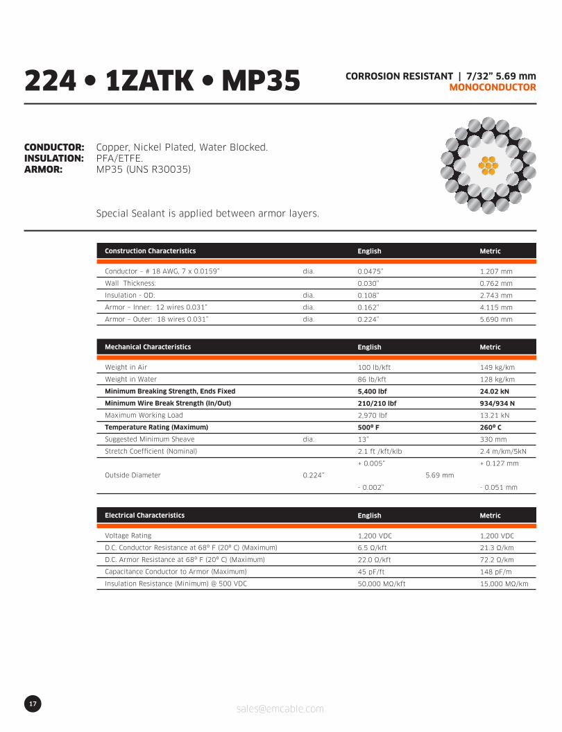
CORROSION RESISTANT | 7/32” 5.69 mmMONOCONDUCTOR
CONDUCTOR:INSULATION:ARMOR:
Copper, Nickel Plated, Water Blocked.PFA/ETFE.MP35 (UNS R30035)
Special Sealant is applied between armor layers.
224 l 1ZATK l MP35
Construction Characteristics
Conductor – # 18 AWG, 7 x 0.0159”
Wall Thickness:
Insulation - OD:
Armor – Inner: 12 wires 0.031”
Armor – Outer: 18 wires 0.031”
English
0.0475”
0.030”
0.108”
0.162”
0.224”
Metric
1.207 mm
0.762 mm
2.743 mm
4.115 mm
5.690 mm
dia.
dia.
dia.
dia.
Electrical Characteristics
Voltage Rating
D.C. Conductor Resistance at 68º F (20º C) (Maximum)
D.C. Armor Resistance at 68º F (20º C) (Maximum)
Capacitance Conductor to Armor (Maximum)
Insulation Resistance (Minimum) @ 500 VDC
English
1,200 VDC
6.5 Ω/kft
22.0 Ω/kft
45 pF/ft
50,000 MΩ/kft
Metric
1,200 VDC
21.3 Ω/km
72.2 Ω/km
148 pF/m
15,000 MΩ/km
dia.
0.224” 5.69 mm
Mechanical Characteristics
Weight in Air
Weight in Water
Minimum Breaking Strength, Ends Fixed
Minimum Wire Break Strength (In/Out)
Maximum Working Load
Temperature Rating (Maximum)
Suggested Minimum Sheave
Stretch Coefficient (Nominal)
Outside Diameter
English
100 lb/kft
86 lb/kft
5,400 lbf
210/210 lbf
2,970 lbf
500º F
13”
2.1 ft /kft/klb
+ 0.005”
- 0.002”
Metric
149 kg/km
128 kg/km
24.02 kN
934/934 N
13.21 kN
260º C
330 mm
2.4 m/km/5kN
+ 0.127 mm
- 0.051 mm

18
1/4” 6.55 mmMONOCONDUCTOR
CONDUCTOR:INSULATION:ARMOR:
Copper, Water Blocked.Polypropylene.Galvanized high strength steel (GEIPS)preformed and coated with a corrosionpreventative lubricant compound.
Special Sealant is applied between armor layers.
258 l 1ZPL l HS
Construction Characteristics
Conductor – # 16 AWG, 19 x 0.0119”
Wall Thickness:
Insulation - OD:
Armor – Inner: 12 wires 0.0358”
Armor – Outer: 18 wires 0.0358”
English
0.059”
0.032”
0.123”
0.186”
0.258”
Metric
1.499 mm
0.813 mm
3.124 mm
4.724 mm
6.553 mm
dia.
dia.
dia.
dia.
Electrical Characteristics
Voltage Rating
D.C. Conductor Resistance at 68º F (20º C) (Maximum)
D.C. Armor Resistance at 68º F (20º C) (Maximum)
Capacitance Conductor to Armor (Maximum)
Insulation Resistance (Minimum) @ 500 VDC
English
1,200 VDC
4.1 Ω/kft
3.3 Ω/kft
52 pF/ft
50,000 MΩ/kft
Metric
1,200 VDC
13.5 Ω/km
10.83 Ω/km
171 pF/m
15,000 MΩ/km
dia.
0.258” 6.55 mm
Mechanical Characteristics
Weight in Air
Weight in Water
Minimum Breaking Strength, Ends Fixed
Minimum Wire Break Strength (In/Out)
Maximum Working Load
Temperature Rating (Maximum)
Suggested Minimum Sheave
Stretch Coefficient (Nominal)
Outside Diameter
English
120 lb/kft
98 lb/kft
8,200 lbf
294/294 lbf
4,510 lbf
300º F
14.3”
1.7 ft /kft/klb
+ 0.005”
- 0.002”
Metric
178 kg/km
146 kg/km
36.48 kN
1308/1308 N
20.06 kN
149º C
363 mm
1.9 m/km/5kN
+ 0.127 mm
- 0.051 mm

19
1/4” 6.55 mmMONOCONDUCTOR
CONDUCTOR:INSULATION:ARMOR:
Copper, Water Blocked.FEP/ETFE.Galvanized high strength steel (GEIPS)preformed and coated with a corrosionpreventative lubricant compound.
Special Sealant is applied between armor layers.
258 l 1ZFTL l HS
Construction Characteristics
Conductor – # 16 AWG, 19 x 0.0119”
Wall Thickness:
Insulation - OD:
Armor – Inner: 12 wires 0.0358”
Armor – Outer: 18 wires 0.0358”
English
0.059”
0.032”
0.123”
0.186”
0.258”
Metric
1.499 mm
0.813 mm
3.214 mm
4.724 mm
6.553 mm
dia.
dia.
dia.
dia.
Electrical Characteristics
Voltage Rating
D.C. Conductor Resistance at 68º F (20º C) (Maximum)
D.C. Armor Resistance at 68º F (20º C) (Maximum)
Capacitance Conductor to Armor (Maximum)
Insulation Resistance (Minimum) @ 500 VDC
English
1,200 VDC
4.1 Ω/kft
3.3 Ω/kft
53 pF/ft
50,000 MΩ/kft
Metric
1,200 VDC
13.5 Ω/km
10.83 Ω/km
174 pF/m
15,000 MΩ/km
dia.
0.258” 6.55 mm
Mechanical Characteristics
Weight in Air
Weight in Water
Minimum Breaking Strength, Ends Fixed
Minimum Wire Break Strength (In/Out)
Maximum Working Load
Temperature Rating (Maximum)
Suggested Minimum Sheave
Stretch Coefficient (Nominal)
Outside Diameter
English
125 lb/kft
102 lb/kft
8,200 lbf
294/294 lbf
4,510 lbf
500º F
14.3”
1.7 ft /kft/klb
+ 0.005”
- 0.002”
Metric
186 kg/km
152 kg/km
36.48 kN
1308/1308 N
20.06 kN
260º C
363 mm
1.9 m/km/5kN
+ 0.127 mm
- 0.051 mm

20
9/32” 7.32 mmMONOCONDUCTOR
CONDUCTOR:INSULATION:ARMOR:
Copper, Water Blocked.Polypropylene.Galvanized high strength steel (GEIPS)preformed and coated with a corrosionpreventative lubricant compound.
Special Sealant is applied between armor layers.
288 l 1ZPL l HS
Construction Characteristics
Conductor – # 15 AWG, 19 x 0.0142”
Wall Thickness:
Insulation - OD:
Armor – Inner: 12 wires 0.0405”
Armor – Outer: 18 wires 0.0405”
English
0.071”
0.0325”
0.136”
0.207”
0.288”
Metric
1.803 mm
0.825 mm
3.454 mm
5.258 mm
7.315 mm
dia.
dia.
dia.
dia.
Electrical Characteristics
Voltage Rating
D.C. Conductor Resistance at 68º F (20º C) (Maximum)
D.C. Armor Resistance at 68º F (20º C) (Maximum)
Capacitance Conductor to Armor (Maximum)
Insulation Resistance (Minimum) @ 500 VDC
English
1,500 VDC
2.8 Ω/kft
2.7 Ω/kft
58 pF/ft
50,000 MΩ/kft
Metric
1,500 VDC
9.2 Ω/km
8.9 Ω/km
190 pF/m
15,000 MΩ/km
dia.
0.288” 6.55 mm
Mechanical Characteristics
Weight in Air
Weight in Water
Minimum Breaking Strength, Ends Fixed
Minimum Wire Break Strength (In/Out)
Maximum Working Load
Temperature Rating (Maximum)
Suggested Minimum Sheave
Stretch Coefficient (Nominal)
Outside Diameter
English
154 lb/kft
130 lb/kft
10,400 lbf
375/375 lbf
5,720 lbf
300º F
16”
1.3 ft /kft/klb
+ 0.005”
- 0.002”
Metric
229 kg/km
194 kg/km
46.26 kN
1668/1668 N
25.44 kN
149º C
406 mm
1.5 m/km/5kN
+ 0.127 mm
- 0.051 mm

21
9/32” 7.32 mmMONOCONDUCTOR
CONDUCTOR:INSULATION:ARMOR:
Copper, Water Blocked.ETFE .Galvanized high strength steel (GEIPS)preformed and coated with a corrosionpreventative lubricant compound.
Special Sealant is applied between armor layers.
288 l 1ZTL l HS
Construction Characteristics
Conductor – # 15 AWG, 19 x 0.0142”
Wall Thickness:
Insulation - OD:
Armor – Inner: 12 wires 0.0405”
Armor – Outer: 18 wires 0.0405”
English
0.071”
0.0325”
0.136”
0.207”
0.288”
Metric
1.803 mm
0.825 mm
3.454 mm
5.258 mm
7.315 mm
dia.
dia.
dia.
dia.
Electrical Characteristics
Voltage Rating
D.C. Conductor Resistance at 68º F (20º C) (Maximum)
D.C. Armor Resistance at 68º F (20º C) (Maximum)
Capacitance Conductor to Armor (Maximum)
Insulation Resistance (Minimum) @ 500 VDC
English
1,500 VDC
2.8 Ω/kft
2.7 Ω/kft
64 pF/ft
50,000 MΩ/kft
Metric
1,500 VDC
9.2 Ω/km
8.9 Ω/km
210 pF/m
15,000 MΩ/km
dia.
0.288” 7.32 mm
Mechanical Characteristics
Weight in Air
Weight in Water
Minimum Breaking Strength, Ends Fixed
Minimum Wire Break Strength (In/Out)
Maximum Working Load
Temperature Rating (Maximum)
Suggested Minimum Sheave
Stretch Coefficient (Nominal)
Outside Diameter
English
158 lb/kft
134 lb/kft
10,400 lbf
375/375 lbf
5,720 lbf
500º F
16”
1.3 ft /kft/klb
+ 0.005”
- 0.002”
Metric
235 kg/km
199 kg/km
46.26 kN
1668/1668 N
25.44 kN
260º C
406 mm
1.5 m/km/5kN
+ 0.127 mm
- 0.051 mm

22
HIGHEST TEMPERATURE (600°F) | 9/32” 7.32 mmMONOCONDUCTOR
CONDUCTOR:INSULATION:ARMOR:
Copper, Water Blocked.ECCTREME.Galvanized high strength steel (GEIPS)preformed and coated with a corrosionpreventative lubricant compound.
Special Sealant is applied between armor layers.
288 l 1ZETL l HS
Construction Characteristics
Conductor – # 15 AWG, 19 x 0.0142”
Wall Thickness:
Insulation - OD:
Armor – Inner: 12 wires 0.0405”
Armor – Outer: 18 wires 0.0405”
English
0.071”
0.0325”
0.136”
0.207”
0.288”
Metric
1.803 mm
0.825 mm
3.454 mm
5.258 mm
7.315 mm
dia.
dia.
dia.
dia.
Electrical Characteristics
Voltage Rating
D.C. Conductor Resistance at 68º F (20º C) (Maximum)
D.C. Armor Resistance at 68º F (20º C) (Maximum)
Capacitance Conductor to Armor (Maximum)
Insulation Resistance (Minimum) @ 500 VDC
English
1,500 VDC
2.8 Ω/kft
2.7 Ω/kft
58 pF/ft
50,000 MΩ/kft
Metric
1,500 VDC
9.2 Ω/km
8.9 Ω/km
190 pF/m
15,000 MΩ/km
dia.
0.288” 7.32 mm
Mechanical Characteristics
Weight in Air
Weight in Water
Minimum Breaking Strength, Ends Fixed
Minimum Wire Break Strength (In/Out)
Maximum Working Load
Temperature Rating (Maximum)
Suggested Minimum Sheave
Stretch Coefficient (Nominal)
Outside Diameter
English
160 lb/kft
138 lb/kft
10,400 lbf
375/375 lbf
5,720 lbf
600º F
16”
1.3 ft /kft/klb
+ 0.005”
- 0.002”
Metric
238 kg/km
205 kg/km
46.26 kN
1668/1668 N
25.44 kN
316º C
406 mm
1.5 m/km/5kN
+ 0.127 mm
- 0.051 mm

23
9/32” 7.32 mmMONOCONDUCTOR
CONDUCTOR:INSULATION:ARMOR:
Copper, Water Blocked.FEP/ETFE .Galvanized high strength steel (GEIPS)preformed and coated with a corrosionpreventative lubricant compound.
Special Sealant is applied between armor layers.
288 l 1ZFTL l HS
Construction Characteristics
Conductor – # 15 AWG, 19 x 0.0142”
Wall Thickness:
Insulation - OD:
Armor – Inner: 12 wires 0.0405”
Armor – Outer: 18 wires 0.0405”
English
0.071”
0.0325”
0.136”
0.207”
0.288”
Metric
1.803 mm
0.825 mm
3.454 mm
5.258 mm
7.315 mm
dia.
dia.
dia.
dia.
Electrical Characteristics
Voltage Rating
D.C. Conductor Resistance at 68º F (20º C) (Maximum)
D.C. Armor Resistance at 68º F (20º C) (Maximum)
Capacitance Conductor to Armor (Maximum)
Insulation Resistance (Minimum) @ 500 VDC
English
1,500 VDC
2.8 Ω/kft
2.7 Ω/kft
58 pF/ft
50,000 MΩ/kft
Metric
1,500 VDC
9.2 Ω/km
8.9 Ω/km
190 pF/m
15,000 MΩ/km
dia.
0.288” 7.32 mm
Mechanical Characteristics
Weight in Air
Weight in Water
Minimum Breaking Strength, Ends Fixed
Minimum Wire Break Strength (In/Out)
Maximum Working Load
Temperature Rating (Maximum)
Suggested Minimum Sheave
Stretch Coefficient (Nominal)
Outside Diameter
English
160 lb/kft
138 lb/kft
10,400 lbf
375/375 lbf
5,720 lbf
500º F
16”
1.3 ft /kft/klb
+ 0.005”
- 0.002”
Metric
238 kg/km
205 kg/km
46.26 kN
1668/1668 N
25.44 kN
260º C
406 mm
1.5 m/km/5kN
+ 0.127 mm
- 0.051 mm
24
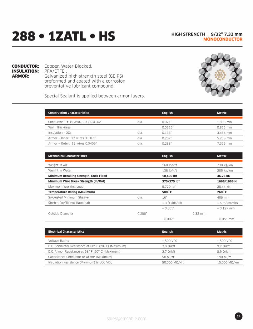
HIGH STRENGTH | 9/32” 7.32 mmMONOCONDUCTOR
CONDUCTOR:INSULATION:ARMOR:
Copper, Water Blocked.PFA/ETFE .Galvanized high strength steel (GEIPS)preformed and coated with a corrosionpreventative lubricant compound.
Special Sealant is applied between armor layers.
288 l 1ZATL l HS
Construction Characteristics
Conductor – # 15 AWG, 19 x 0.0142”
Wall Thickness:
Insulation - OD:
Armor – Inner: 12 wires 0.0405”
Armor – Outer: 18 wires 0.0405”
English
0.071”
0.0325”
0.136”
0.207”
0.288”
Metric
1.803 mm
0.825 mm
3.454 mm
5.258 mm
7.315 mm
dia.
dia.
dia.
dia.
Electrical Characteristics
Voltage Rating
D.C. Conductor Resistance at 68º F (20º C) (Maximum)
D.C. Armor Resistance at 68º F (20º C) (Maximum)
Capacitance Conductor to Armor (Maximum)
Insulation Resistance (Minimum) @ 500 VDC
English
1,500 VDC
2.8 Ω/kft
2.7 Ω/kft
58 pF/ft
50,000 MΩ/kft
Metric
1,500 VDC
9.2 Ω/km
8.9 Ω/km
190 pF/m
15,000 MΩ/km
dia.
0.288” 7.32 mm
Mechanical Characteristics
Weight in Air
Weight in Water
Minimum Breaking Strength, Ends Fixed
Minimum Wire Break Strength (In/Out)
Maximum Working Load
Temperature Rating (Maximum)
Suggested Minimum Sheave
Stretch Coefficient (Nominal)
Outside Diameter
English
160 lb/kft
138 lb/kft
10,400 lbf
375/375 lbf
5,720 lbf
500º F
16”
1.3 ft /kft/klb
+ 0.005”
- 0.002”
Metric
238 kg/km
205 kg/km
46.26 kN
1668/1668 N
25.44 kN
260º C
406 mm
1.5 m/km/5kN
+ 0.127 mm
- 0.051 mm
25
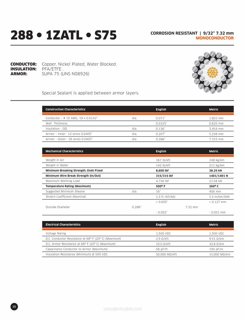
CORROSION RESISTANT | 9/32” 7.32 mmMONOCONDUCTOR
CONDUCTOR:INSULATION:ARMOR:
Copper, Nickel Plated, Water Blocked.PFA/ETFE .SUPA 75 (UNS N08926)
Special Sealant is applied between armor layers.
288 l 1ZATL l S75
Construction Characteristics
Conductor – # 15 AWG, 19 x 0.0142”
Wall Thickness:
Insulation - OD:
Armor – Inner: 12 wires 0.0405”
Armor – Outer: 18 wires 0.0405”
English
0.071”
0.0325”
0.136”
0.207”
0.288”
Metric
1.803 mm
0.825 mm
3.454 mm
5.258 mm
7.315 mm
dia.
dia.
dia.
dia.
Electrical Characteristics
Voltage Rating
D.C. Conductor Resistance at 68º F (20º C) (Maximum)
D.C. Armor Resistance at 68º F (20º C) (Maximum)
Capacitance Conductor to Armor (Maximum)
Insulation Resistance (Minimum) @ 500 VDC
English
1,500 VDC
2.9 Ω/kft
10.0 Ω/kft
58 pF/ft
50,000 MΩ/kft
Metric
1,500 VDC
9.51 Ω/km
32.8 Ω/km
190 pF/m
15,000 MΩ/km
dia.
0.288” 7.32 mm
Mechanical Characteristics
Weight in Air
Weight in Water
Minimum Breaking Strength, Ends Fixed
Minimum Wire Break Strength (In/Out)
Maximum Working Load
Temperature Rating (Maximum)
Suggested Minimum Sheave
Stretch Coefficient (Nominal)
Outside Diameter
English
167 lb/kft
142 lb/kft
8,600 lbf
315/315 lbf
4,730 lbf
500º F
16”
1.3 ft /kft/klb
+ 0.005”
- 0.002”
Metric
248 kg/km
211 kg/km
38.25 kN
1401/1401 N
21.04 kN
260º C
406 mm
1.5 m/km/5kN
+ 0.127 mm
- 0.051 mm

26
CORROSION RESISTANT | 9/32” 7.32 mmMONOCONDUCTOR
CONDUCTOR:INSULATION:ARMOR:
Copper, Nickel Plated, Water Blocked.PFA/ETFE .SUPA 77 (UNS S31277)
Special Sealant is applied between armor layers.
288 l 1ZATL l S77
Construction Characteristics
Conductor – # 15 AWG, 19 x 0.0142”
Wall Thickness:
Insulation - OD:
Armor – Inner: 12 wires 0.0405”
Armor – Outer: 18 wires 0.0405”
English
0.071”
0.0325”
0.136”
0.207”
0.288”
Metric
1.803 mm
0.825 mm
3.454 mm
5.258 mm
7.315 mm
dia.
dia.
dia.
dia.
Electrical Characteristics
Voltage Rating
D.C. Conductor Resistance at 68º F (20º C) (Maximum)
D.C. Armor Resistance at 68º F (20º C) (Maximum)
Capacitance Conductor to Armor (Maximum)
Insulation Resistance (Minimum) @ 500 VDC
English
1,500 VDC
2.9 Ω/kft
12.8 Ω/kft
58 pF/ft
50,000 MΩ/kft
Metric
1,500 VDC
9.51 Ω/km
41.98 Ω/km
190 pF/m
15,000 MΩ/km
dia.
0.288” 7.32 mm
Mechanical Characteristics
Weight in Air
Weight in Water
Minimum Breaking Strength, Ends Fixed
Minimum Wire Break Strength (In/Out)
Maximum Working Load
Temperature Rating (Maximum)
Suggested Minimum Sheave
Stretch Coefficient (Nominal)
Outside Diameter
English
167 lb/kft
142 lb/kft
8,900 lbf
320/320 lbf
4,895 lbf
500º F
16”
1.3 ft /kft/klb
+ 0.005”
- 0.002”
Metric
248 kg/km
211 kg/km
39.59 kN
1423/1423 N
21.77 kN
260º C
406 mm
1.5 m/km/5kN
+ 0.127 mm
- 0.051 mm

27
CORROSION RESISTANT | 9/32” 7.32 mmMONOCONDUCTOR
CONDUCTOR:INSULATION:ARMOR:
Copper, Nickel Plated, Water Blocked.PFA/ETFE .MP35 (UNS R30035)
Special Sealant is applied between armor layers.
288 l 1ZATL l MP35
Construction Characteristics
Conductor – # 15 AWG, 19 x 0.0142”
Wall Thickness:
Insulation - OD:
Armor – Inner: 12 wires 0.0405”
Armor – Outer: 18 wires 0.0405”
English
0.071”
0.0325”
0.136”
0.207”
0.288”
Metric
1.803 mm
0.825 mm
3.454 mm
5.258 mm
7.315 mm
dia.
dia.
dia.
dia.
Electrical Characteristics
Voltage Rating
D.C. Conductor Resistance at 68º F (20º C) (Maximum)
D.C. Armor Resistance at 68º F (20º C) (Maximum)
Capacitance Conductor to Armor (Maximum)
Insulation Resistance (Minimum) @ 500 VDC
English
1,500 VDC
2.9 Ω/kft
13.0 Ω/kft
58 pF/ft
50,000 MΩ/kft
Metric
1,500 VDC
9.51 Ω/km
41.98 Ω/km
190 pF/m
15,000 MΩ/km
dia.
0.288” 7.32 mm
Mechanical Characteristics
Weight in Air
Weight in Water
Minimum Breaking Strength, Ends Fixed
Minimum Wire Break Strength (In/Out)
Maximum Working Load
Temperature Rating (Maximum)
Suggested Minimum Sheave
Stretch Coefficient (Nominal)
Outside Diameter
English
174 lb/kft
142 lb/kft
9,400 lbf
347/347 lbf
5,170 lbf
500º F
16”
1.2 ft /kft/klb
+ 0.005”
- 0.002”
Metric
258 kg/km
220 kg/km
41.81 kN
1543/1543 N
23.00 kN
260º C
406 mm
1.4 m/km/5kN
+ 0.127 mm
- 0.051 mm
28
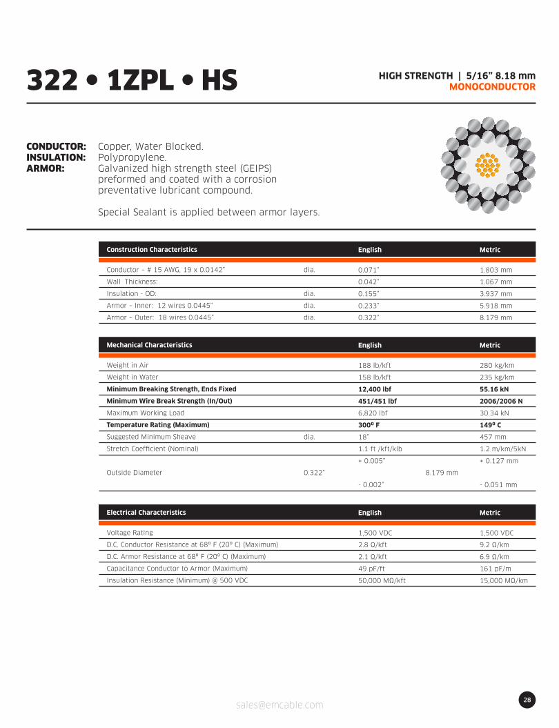
HIGH STRENGTH | 5/16” 8.18 mmMONOCONDUCTOR
CONDUCTOR:INSULATION:ARMOR:
Copper, Water Blocked.Polypropylene.Galvanized high strength steel (GEIPS)preformed and coated with a corrosionpreventative lubricant compound.
Special Sealant is applied between armor layers.
322 l 1ZPL l HS
Construction Characteristics
Conductor – # 15 AWG, 19 x 0.0142”
Wall Thickness:
Insulation - OD:
Armor – Inner: 12 wires 0.0445”
Armor – Outer: 18 wires 0.0445”
English
0.071”
0.042”
0.155”
0.233”
0.322”
Metric
1.803 mm
1.067 mm
3.937 mm
5.918 mm
8.179 mm
dia.
dia.
dia.
dia.
Electrical Characteristics
Voltage Rating
D.C. Conductor Resistance at 68º F (20º C) (Maximum)
D.C. Armor Resistance at 68º F (20º C) (Maximum)
Capacitance Conductor to Armor (Maximum)
Insulation Resistance (Minimum) @ 500 VDC
English
1,500 VDC
2.8 Ω/kft
2.1 Ω/kft
49 pF/ft
50,000 MΩ/kft
Metric
1,500 VDC
9.2 Ω/km
6.9 Ω/km
161 pF/m
15,000 MΩ/km
dia.
0.322” 8.179 mm
Mechanical Characteristics
Weight in Air
Weight in Water
Minimum Breaking Strength, Ends Fixed
Minimum Wire Break Strength (In/Out)
Maximum Working Load
Temperature Rating (Maximum)
Suggested Minimum Sheave
Stretch Coefficient (Nominal)
Outside Diameter
English
188 lb/kft
158 lb/kft
12,400 lbf
451/451 lbf
6,820 lbf
300º F
18”
1.1 ft /kft/klb
+ 0.005”
- 0.002”
Metric
280 kg/km
235 kg/km
55.16 kN
2006/2006 N
30.34 kN
149º C
457 mm
1.2 m/km/5kN
+ 0.127 mm
- 0.051 mm

29
HIGHEST TEMPERATURE (600°F) | 5/16” 8.18 mmMONOCONDUCTOR
CONDUCTOR:INSULATION:ARMOR:
Copper, Water Blocked.ECCTREME.Galvanized high strength steel (GEIPS)preformed and coated with a corrosionpreventative lubricant compound.
Special Sealant is applied between armor layers.
322 l 1ZETL l HS
Construction Characteristics
Conductor – # 15 AWG, 19 x 0.0142”
Wall Thickness:
Insulation - OD:
Armor – Inner: 12 wires 0.0445”
Armor – Outer: 18 wires 0.0445”
English
0.071”
0.042”
0.155”
0.233”
0.322”
Metric
1.803 mm
1.067 mm
3.937 mm
5.918 mm
8.179 mm
dia.
dia.
dia.
dia.
Electrical Characteristics
Voltage Rating
D.C. Conductor Resistance at 68º F (20º C) (Maximum)
D.C. Armor Resistance at 68º F (20º C) (Maximum)
Capacitance Conductor to Armor (Maximum)
Insulation Resistance (Minimum) @ 500 VDC
English
1,500 VDC
2.8 Ω/kft
2.1 Ω/kft
48 pF/ft
50,000 MΩ/kft
Metric
1,500 VDC
9.2 Ω/km
6.9 Ω/km
157 pF/m
15,000 MΩ/km
dia.
0.322” 8.179 mm
Mechanical Characteristics
Weight in Air
Weight in Water
Minimum Breaking Strength, Ends Fixed
Minimum Wire Break Strength (In/Out)
Maximum Working Load
Temperature Rating (Maximum)
Suggested Minimum Sheave
Stretch Coefficient (Nominal)
Outside Diameter
English
195 lb/kft
165 lb/kft
12,400 lbf
451/451 lbf
6,820 lbf
600º F
18”
1.1 ft /kft/klb
+ 0.005”
- 0.002”
Metric
290 kg/km
246 kg/km
55.16 kN
2006/2006 N
30.34 kN
316º C
457 mm
1.2 m/km/5kN
+ 0.127 mm
- 0.051 mm

30
5/16” 8.18 mmMONOCONDUCTOR
CONDUCTOR:INSULATION:ARMOR:
Copper, Water Blocked.FEP/ETFE .Galvanized high strength steel (GEIPS)preformed and coated with a corrosionpreventative lubricant compound.
Special Sealant is applied between armor layers.
322 l 1ZFTL l HS
Construction Characteristics
Conductor – # 15 AWG, 19 x 0.0142”
Wall Thickness:
Insulation - OD:
Armor – Inner: 12 wires 0.0445”
Armor – Outer: 18 wires 0.0445”
English
0.071”
0.042”
0.155”
0.233”
0.322”
Metric
1.803 mm
1.067 mm
3.937 mm
5.918 mm
8.179 mm
dia.
dia.
dia.
dia.
Electrical Characteristics
Voltage Rating
D.C. Conductor Resistance at 68º F (20º C) (Maximum)
D.C. Armor Resistance at 68º F (20º C) (Maximum)
Capacitance Conductor to Armor (Maximum)
Insulation Resistance (Minimum) @ 500 VDC
English
1,500 VDC
2.8 Ω/kft
2.1 Ω/kft
48 pF/ft
50,000 MΩ/kft
Metric
1,500 VDC
9.2 Ω/km
6.9 Ω/km
157 pF/m
15,000 MΩ/km
dia.
0.322” 8.179 mm
Mechanical Characteristics
Weight in Air
Weight in Water
Minimum Breaking Strength, Ends Fixed
Minimum Wire Break Strength (In/Out)
Maximum Working Load
Temperature Rating (Maximum)
Suggested Minimum Sheave
Stretch Coefficient (Nominal)
Outside Diameter
English
195 lb/kft
165 lb/kft
12,400 lbf
451/451 lbf
6,820 lbf
500º F
18”
1.1 ft /kft/klb
+ 0.005”
- 0.002”
Metric
290 kg/km
246 kg/km
55.16 kN
2006/2006 N
30.34 kN
260º C
457 mm
1.2 m/km/5kN
+ 0.127 mm
- 0.051 mm
31
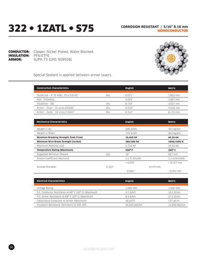
CORROSION RESISTANT | 5/16” 8.18 mmMONOCONDUCTOR
CONDUCTOR:INSULATION:ARMOR:
Copper, Nickel Plated, Water Blocked.PFA/ETFE .SUPA 75 (UNS N08926)
Special Sealant is applied between armor layers.
322 l 1ZATL l S75
Construction Characteristics
Conductor – # 15 AWG, 19 x 0.0142”
Wall Thickness:
Insulation - OD:
Armor – Inner: 12 wires 0.0445”
Armor – Outer: 18 wires 0.0445”
English
0.071”
0.042”
0.155”
0.233”
0.322”
Metric
1.803 mm
1.067 mm
3.937 mm
5.918 mm
8.179 mm
dia.
dia.
dia.
dia.
Electrical Characteristics
Voltage Rating
D.C. Conductor Resistance at 68º F (20º C) (Maximum)
D.C. Armor Resistance at 68º F (20º C) (Maximum)
Capacitance Conductor to Armor (Maximum)
Insulation Resistance (Minimum) @ 500 VDC
English
1,500 VDC
3.1 Ω/kft
8.3 Ω/kft
48 pF/ft
50,000 MΩ/kft
Metric
1,500 VDC
10.2 Ω/km
27.2 Ω/km
157 pF/m
15,000 MΩ/km
dia.
0.322” 8.179 mm
Mechanical Characteristics
Weight in Air
Weight in Water
Minimum Breaking Strength, Ends Fixed
Minimum Wire Break Strength (In/Out)
Maximum Working Load
Temperature Rating (Maximum)
Suggested Minimum Sheave
Stretch Coefficient (Nominal)
Outside Diameter
English
206 lb/kft
176 lb/kft
10,400 lbf
380/380 lbf
5,720 lbf
500º F
18”
1.1 ft /kft/klb
+ 0.005”
- 0.002”
Metric
307 kg/km
262 kg/km
46.26 kN
1690/1690 N
25.44 kN
260º C
457 mm
1.2 m/km/5kN
+ 0.127 mm
- 0.051 mm

32
CORROSION RESISTANT | 5/16” 8.18 mmMONOCONDUCTOR
CONDUCTOR:INSULATION:ARMOR:
Copper, Nickel Plated, Water Blocked.PFA/ETFE .SUPA 77 (UNS S31277)
Special Sealant is applied between armor layers.
322 l 1ZATL l S77
Construction Characteristics
Conductor – # 15 AWG, 19 x 0.0142”
Wall Thickness:
Insulation - OD:
Armor – Inner: 12 wires 0.0445”
Armor – Outer: 18 wires 0.0445”
English
0.071”
0.042”
0.155”
0.233”
0.322”
Metric
1.803 mm
1.067 mm
3.937 mm
5.918 mm
8.179 mm
dia.
dia.
dia.
dia.
Electrical Characteristics
Voltage Rating
D.C. Conductor Resistance at 68º F (20º C) (Maximum)
D.C. Armor Resistance at 68º F (20º C) (Maximum)
Capacitance Conductor to Armor (Maximum)
Insulation Resistance (Minimum) @ 500 VDC
English
1,500 VDC
3.1 Ω/kft
10.4 Ω/kft
48 pF/ft
50,000 MΩ/kft
Metric
1,500 VDC
10.2 Ω/km
34.1 Ω/km
157 pF/m
15,000 MΩ/km
dia.
0.322” 8.179 mm
Mechanical Characteristics
Weight in Air
Weight in Water
Minimum Breaking Strength, Ends Fixed
Minimum Wire Break Strength (In/Out)
Maximum Working Load
Temperature Rating (Maximum)
Suggested Minimum Sheave
Stretch Coefficient (Nominal)
Outside Diameter
English
206 lb/kft
176 lb/kft
10,600 lbf
387/387 lbf
5,830 lbf
500º F
18”
1.1 ft /kft/klb
+ 0.005”
- 0.002”
Metric
307 kg/km
262 kg/km
47.15 kN
1721/1721 N
25.93 kN
260º C
457 mm
1.2 m/km/5kN
+ 0.127 mm
- 0.051 mm
33
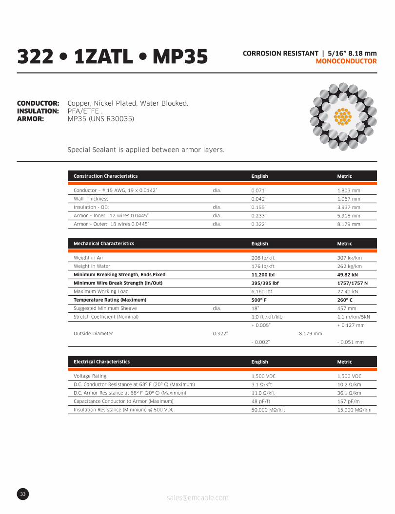
CORROSION RESISTANT | 5/16” 8.18 mmMONOCONDUCTOR
CONDUCTOR:INSULATION:ARMOR:
Copper, Nickel Plated, Water Blocked.PFA/ETFE .MP35 (UNS R30035)
Special Sealant is applied between armor layers.
322 l 1ZATL l MP35
Construction Characteristics
Conductor – # 15 AWG, 19 x 0.0142”
Wall Thickness:
Insulation - OD:
Armor – Inner: 12 wires 0.0445”
Armor – Outer: 18 wires 0.0445”
English
0.071”
0.042”
0.155”
0.233”
0.322”
Metric
1.803 mm
1.067 mm
3.937 mm
5.918 mm
8.179 mm
dia.
dia.
dia.
dia.
Electrical Characteristics
Voltage Rating
D.C. Conductor Resistance at 68º F (20º C) (Maximum)
D.C. Armor Resistance at 68º F (20º C) (Maximum)
Capacitance Conductor to Armor (Maximum)
Insulation Resistance (Minimum) @ 500 VDC
English
1,500 VDC
3.1 Ω/kft
11.0 Ω/kft
48 pF/ft
50,000 MΩ/kft
Metric
1,500 VDC
10.2 Ω/km
36.1 Ω/km
157 pF/m
15,000 MΩ/km
dia.
0.322” 8.179 mm
Mechanical Characteristics
Weight in Air
Weight in Water
Minimum Breaking Strength, Ends Fixed
Minimum Wire Break Strength (In/Out)
Maximum Working Load
Temperature Rating (Maximum)
Suggested Minimum Sheave
Stretch Coefficient (Nominal)
Outside Diameter
English
206 lb/kft
176 lb/kft
11,200 lbf
395/395 lbf
6,160 lbf
500º F
18”
1.0 ft /kft/klb
+ 0.005”
- 0.002”
Metric
307 kg/km
262 kg/km
49.82 kN
1757/1757 N
27.40 kN
260º C
457 mm
1.1 m/km/5kN
+ 0.127 mm
- 0.051 mm
34
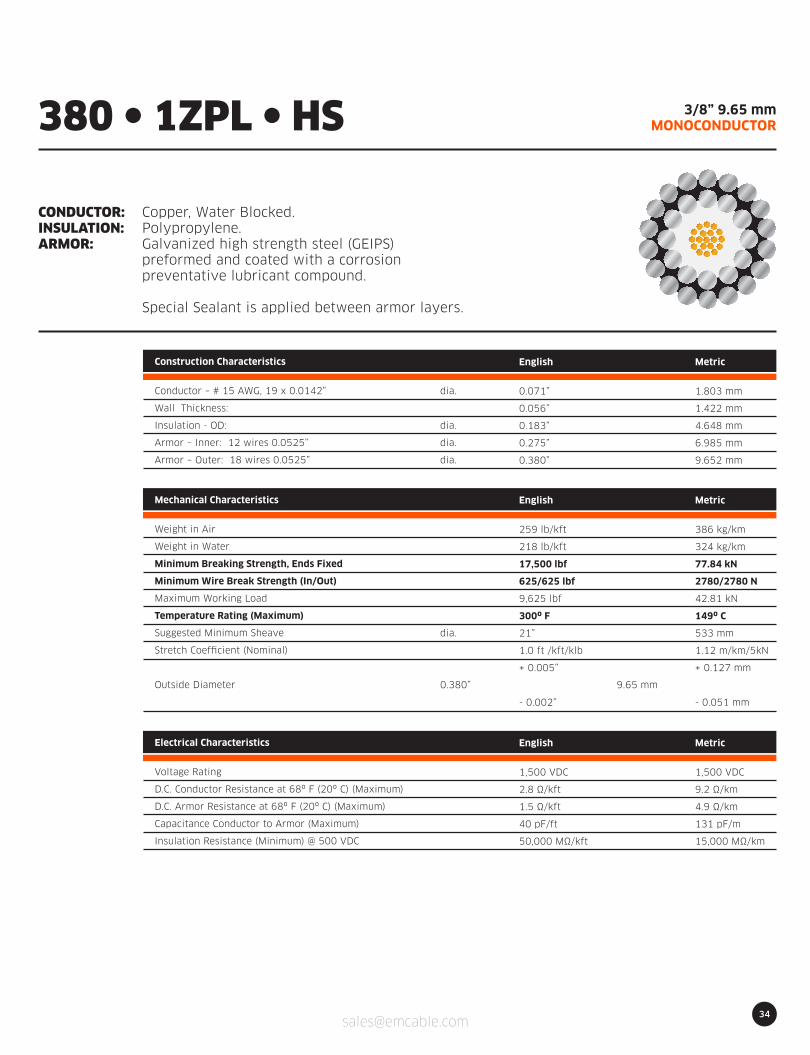
3/8” 9.65 mmMONOCONDUCTOR
CONDUCTOR:INSULATION:ARMOR:
Copper, Water Blocked.Polypropylene.Galvanized high strength steel (GEIPS)preformed and coated with a corrosionpreventative lubricant compound.
Special Sealant is applied between armor layers.
380 l 1ZPL l HS
Construction Characteristics
Conductor – # 15 AWG, 19 x 0.0142”
Wall Thickness:
Insulation - OD:
Armor – Inner: 12 wires 0.0525”
Armor – Outer: 18 wires 0.0525”
English
0.071”
0.056”
0.183”
0.275”
0.380”
Metric
1.803 mm
1.422 mm
4.648 mm
6.985 mm
9.652 mm
dia.
dia.
dia.
dia.
Electrical Characteristics
Voltage Rating
D.C. Conductor Resistance at 68º F (20º C) (Maximum)
D.C. Armor Resistance at 68º F (20º C) (Maximum)
Capacitance Conductor to Armor (Maximum)
Insulation Resistance (Minimum) @ 500 VDC
English
1,500 VDC
2.8 Ω/kft
1.5 Ω/kft
40 pF/ft
50,000 MΩ/kft
Metric
1,500 VDC
9.2 Ω/km
4.9 Ω/km
131 pF/m
15,000 MΩ/km
dia.
0.380” 9.65 mm
Mechanical Characteristics
Weight in Air
Weight in Water
Minimum Breaking Strength, Ends Fixed
Minimum Wire Break Strength (In/Out)
Maximum Working Load
Temperature Rating (Maximum)
Suggested Minimum Sheave
Stretch Coefficient (Nominal)
Outside Diameter
English
259 lb/kft
218 lb/kft
17,500 lbf
625/625 lbf
9,625 lbf
300º F
21”
1.0 ft /kft/klb
+ 0.005”
- 0.002”
Metric
386 kg/km
324 kg/km
77.84 kN
2780/2780 N
42.81 kN
149º C
533 mm
1.12 m/km/5kN
+ 0.127 mm
- 0.051 mm
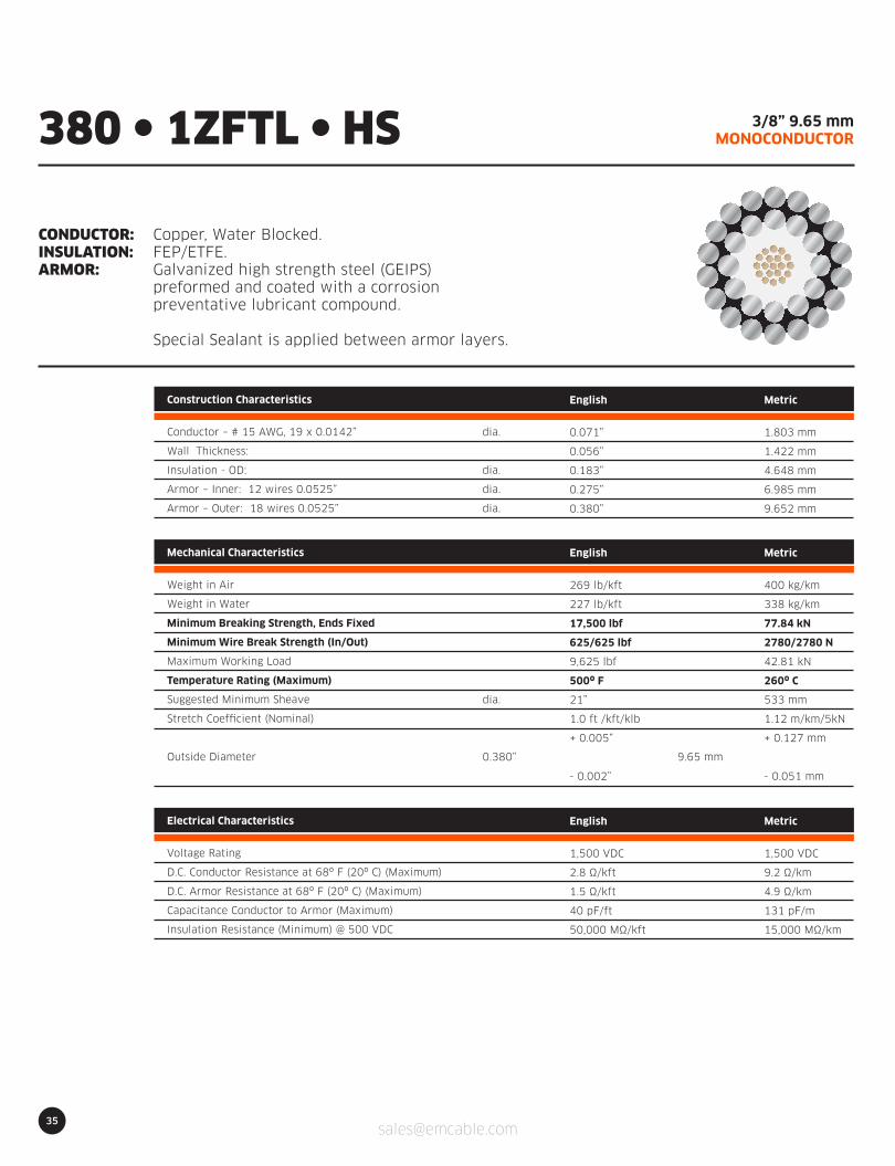
35
3/8” 9.65 mmMONOCONDUCTOR
CONDUCTOR:INSULATION:ARMOR:
Copper, Water Blocked.FEP/ETFE.Galvanized high strength steel (GEIPS)preformed and coated with a corrosionpreventative lubricant compound.
Special Sealant is applied between armor layers.
380 l 1ZFTL l HS
Construction Characteristics
Conductor – # 15 AWG, 19 x 0.0142”
Wall Thickness:
Insulation - OD:
Armor – Inner: 12 wires 0.0525”
Armor – Outer: 18 wires 0.0525”
English
0.071”
0.056”
0.183”
0.275”
0.380”
Metric
1.803 mm
1.422 mm
4.648 mm
6.985 mm
9.652 mm
dia.
dia.
dia.
dia.
Electrical Characteristics
Voltage Rating
D.C. Conductor Resistance at 68º F (20º C) (Maximum)
D.C. Armor Resistance at 68º F (20º C) (Maximum)
Capacitance Conductor to Armor (Maximum)
Insulation Resistance (Minimum) @ 500 VDC
English
1,500 VDC
2.8 Ω/kft
1.5 Ω/kft
40 pF/ft
50,000 MΩ/kft
Metric
1,500 VDC
9.2 Ω/km
4.9 Ω/km
131 pF/m
15,000 MΩ/km
dia.
0.380” 9.65 mm
Mechanical Characteristics
Weight in Air
Weight in Water
Minimum Breaking Strength, Ends Fixed
Minimum Wire Break Strength (In/Out)
Maximum Working Load
Temperature Rating (Maximum)
Suggested Minimum Sheave
Stretch Coefficient (Nominal)
Outside Diameter
English
269 lb/kft
227 lb/kft
17,500 lbf
625/625 lbf
9,625 lbf
500º F
21”
1.0 ft /kft/klb
+ 0.005”
- 0.002”
Metric
400 kg/km
338 kg/km
77.84 kN
2780/2780 N
42.81 kN
260º C
533 mm
1.12 m/km/5kN
+ 0.127 mm
- 0.051 mm
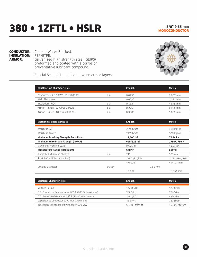
36
3/8” 9.65 mmMONOCONDUCTOR
CONDUCTOR:INSULATION:ARMOR:
Copper, Water Blocked.FEP/ETFE.Galvanized high strength steel (GEIPS)preformed and coated with a corrosionpreventative lubricant compound.
Special Sealant is applied between armor layers.
380 l 1ZFTL l HSLR
Construction Characteristics
Conductor – # 13 AWG, 19 x 0.0159”
Wall Thickness:
Insulation - OD:
Armor – Inner: 12 wires 0.0525”
Armor – Outer: 18 wires 0.0525”
English
0.079”
0.052”
0.183”
0.275”
0.380”
Metric
2.007 mm
1.321 mm
4.648 mm
6.985 mm
9.652 mm
dia.
dia.
dia.
dia.
Electrical Characteristics
Voltage Rating
D.C. Conductor Resistance at 68º F (20º C) (Maximum)
D.C. Armor Resistance at 68º F (20º C) (Maximum)
Capacitance Conductor to Armor (Maximum)
Insulation Resistance (Minimum) @ 500 VDC
English
1,500 VDC
2.3 Ω/kft
1.5 Ω/kft
46 pF/ft
50,000 MΩ/kft
Metric
1,500 VDC
7.5 Ω/km
4.9 Ω/km
151 pF/m
15,000 MΩ/km
dia.
0.380” 9.65 mm
Mechanical Characteristics
Weight in Air
Weight in Water
Minimum Breaking Strength, Ends Fixed
Minimum Wire Break Strength (In/Out)
Maximum Working Load
Temperature Rating (Maximum)
Suggested Minimum Sheave
Stretch Coefficient (Nominal)
Outside Diameter
English
269 lb/kft
227 lb/kft
17,500 lbf
625/625 lbf
9,625 lbf
500º F
21”
1.0 ft /kft/klb
+ 0.005”
- 0.002”
Metric
400 kg/km
338 kg/km
77.84 kN
2780/2780 N
42.81 kN
260º C
533 mm
1.12 m/km/5kN
+ 0.127 mm
- 0.051 mm

37
7/16” 10.80 mmMONOCONDUCTOR
CONDUCTOR:INSULATION:ARMOR:
Copper, Water Blocked.Polypropylene.Galvanized high strength steel (GEIPS)preformed and coated with a corrosionpreventative lubricant compound.
Special Sealant is applied between armor layers.
425 l 1ZPL l HS
Construction Characteristics
Conductor – # 15 AWG, 19 x 0.0142”
Wall Thickness:
Insulation - OD:
Armor – Inner: 12 wires 0.0585”
Armor – Outer: 18 wires 0.0585”
English
0.071”
0.067”
0.205”
0.308”
0.425”
Metric
1.803 mm
1.702 mm
5.207 mm
7.823 mm
10.795 mm
dia.
dia.
dia.
dia.
Electrical Characteristics
Voltage Rating
D.C. Conductor Resistance at 68º F (20º C) (Maximum)
D.C. Armor Resistance at 68º F (20º C) (Maximum)
Capacitance Conductor to Armor (Maximum)
Insulation Resistance (Minimum) @ 500 VDC
English
1,500 VDC
2.8 Ω/kft
1.2 Ω/kft
36 pF/ft
50,000 MΩ/kft
Metric
1,500 VDC
9.2 Ω/km
3.9 Ω/km
118 pF/m
15,000 MΩ/km
dia.
0.425” 10.8 mm
Mechanical Characteristics
Weight in Air
Weight in Water
Minimum Breaking Strength, Ends Fixed
Minimum Wire Break Strength (In/Out)
Maximum Working Load
Temperature Rating (Maximum)
Suggested Minimum Sheave
Stretch Coefficient (Nominal)
Outside Diameter
English
325 lb/kft
273 lb/kft
22,000 lbf
773/773 lbf
12,100 lbf
300º F
24”
0.70 ft /kft/klb
+ 0.005”
- 0.002”
Metric
484 kg/km
406 kg/km
97.86 kN
3438/3438 N
53.82 kN
149º C
610 mm
0.79 m/km/5kN
+ 0.127 mm
- 0.051 mm
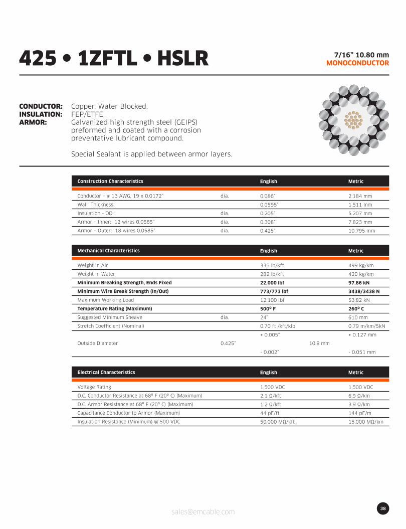
38
7/16” 10.80 mmMONOCONDUCTOR
CONDUCTOR:INSULATION:ARMOR:
Copper, Water Blocked.FEP/ETFE.Galvanized high strength steel (GEIPS)preformed and coated with a corrosionpreventative lubricant compound.
Special Sealant is applied between armor layers.
425 l 1ZFTL l HSLR
Construction Characteristics
Conductor – # 13 AWG, 19 x 0.0172”
Wall Thickness:
Insulation - OD:
Armor – Inner: 12 wires 0.0585”
Armor – Outer: 18 wires 0.0585”
English
0.086”
0.0595”
0.205”
0.308”
0.425”
Metric
2.184 mm
1.511 mm
5.207 mm
7.823 mm
10.795 mm
dia.
dia.
dia.
dia.
Electrical Characteristics
Voltage Rating
D.C. Conductor Resistance at 68º F (20º C) (Maximum)
D.C. Armor Resistance at 68º F (20º C) (Maximum)
Capacitance Conductor to Armor (Maximum)
Insulation Resistance (Minimum) @ 500 VDC
English
1,500 VDC
2.1 Ω/kft
1.2 Ω/kft
44 pF/ft
50,000 MΩ/kft
Metric
1,500 VDC
6.9 Ω/km
3.9 Ω/km
144 pF/m
15,000 MΩ/km
dia.
0.425” 10.8 mm
Mechanical Characteristics
Weight in Air
Weight in Water
Minimum Breaking Strength, Ends Fixed
Minimum Wire Break Strength (In/Out)
Maximum Working Load
Temperature Rating (Maximum)
Suggested Minimum Sheave
Stretch Coefficient (Nominal)
Outside Diameter
English
335 lb/kft
282 lb/kft
22,000 lbf
773/773 lbf
12,100 lbf
500º F
24”
0.70 ft /kft/klb
+ 0.005”
- 0.002”
Metric
499 kg/km
420 kg/km
97.86 kN
3438/3438 N
53.82 kN
260º C
610 mm
0.79 m/km/5kN
+ 0.127 mm
- 0.051 mm
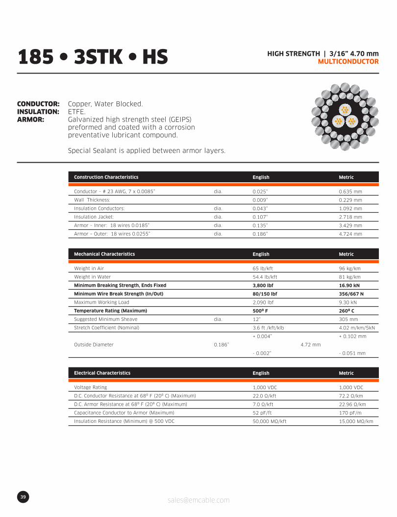
39
HIGH STRENGTH | 3/16” 4.70 mmMULTICONDUCTOR
CONDUCTOR:INSULATION:ARMOR:
Copper, Water Blocked.ETFE.Galvanized high strength steel (GEIPS)preformed and coated with a corrosionpreventative lubricant compound.
Special Sealant is applied between armor layers.
185 l 3STK l HS
Construction Characteristics
Conductor – # 23 AWG, 7 x 0.0085”
Wall Thickness:
Insulation Conductors:
Insulation Jacket:
Armor – Inner: 18 wires 0.0185”
Armor – Outer: 18 wires 0.0255”
English
0.025”
0.009”
0.043”
0.107“
0.135”
0.186”
Metric
0.635 mm
0.229 mm
1.092 mm
2.718 mm
3.429 mm
4.724 mm
dia.
dia.
dia.
dia.
dia.
Electrical Characteristics
Voltage Rating
D.C. Conductor Resistance at 68º F (20º C) (Maximum)
D.C. Armor Resistance at 68º F (20º C) (Maximum)
Capacitance Conductor to Armor (Maximum)
Insulation Resistance (Minimum) @ 500 VDC
English
1,000 VDC
22.0 Ω/kft
7.0 Ω/kft
52 pF/ft
50,000 MΩ/kft
Metric
1,000 VDC
72.2 Ω/km
22.96 Ω/km
170 pF/m
15,000 MΩ/km
dia.
0.186” 4.72 mm
Mechanical Characteristics
Weight in Air
Weight in Water
Minimum Breaking Strength, Ends Fixed
Minimum Wire Break Strength (In/Out)
Maximum Working Load
Temperature Rating (Maximum)
Suggested Minimum Sheave
Stretch Coefficient (Nominal)
Outside Diameter
English
65 lb/kft
54.4 lb/kft
3,800 lbf
80/150 lbf
2,090 lbf
500º F
12”
3.6 ft /kft/klb
+ 0.004”
- 0.002”
Metric
96 kg/km
81 kg/km
16.90 kN
356/667 N
9.30 kN
260º C
305 mm
4.02 m/km/5kN
+ 0.102 mm
- 0.051 mm
40
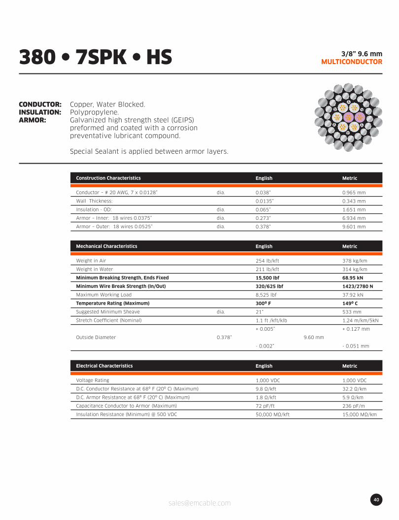
3/8” 9.6 mmMULTICONDUCTOR
CONDUCTOR:INSULATION:ARMOR:
Copper, Water Blocked.Polypropylene.Galvanized high strength steel (GEIPS)preformed and coated with a corrosionpreventative lubricant compound.
Special Sealant is applied between armor layers.
380 l 7SPK l HS
Construction Characteristics
Conductor – # 20 AWG, 7 x 0.0128”
Wall Thickness:
Insulation - OD:
Armor – Inner: 18 wires 0.0375”
Armor – Outer: 18 wires 0.0525”
English
0.038”
0.0135”
0.065”
0.273”
0.378”
Metric
0.965 mm
0.343 mm
1.651 mm
6.934 mm
9.601 mm
dia.
dia.
dia.
dia.
Electrical Characteristics
Voltage Rating
D.C. Conductor Resistance at 68º F (20º C) (Maximum)
D.C. Armor Resistance at 68º F (20º C) (Maximum)
Capacitance Conductor to Armor (Maximum)
Insulation Resistance (Minimum) @ 500 VDC
English
1,000 VDC
9.8 Ω/kft
1.8 Ω/kft
72 pF/ft
50,000 MΩ/kft
Metric
1,000 VDC
32.2 Ω/km
5.9 Ω/km
236 pF/m
15,000 MΩ/km
dia.
0.378” 9.60 mm
Mechanical Characteristics
Weight in Air
Weight in Water
Minimum Breaking Strength, Ends Fixed
Minimum Wire Break Strength (In/Out)
Maximum Working Load
Temperature Rating (Maximum)
Suggested Minimum Sheave
Stretch Coefficient (Nominal)
Outside Diameter
English
254 lb/kft
211 lb/kft
15,500 lbf
320/625 lbf
8,525 lbf
300º F
21”
1.1 ft /kft/klb
+ 0.005”
- 0.002”
Metric
378 kg/km
314 kg/km
68.95 kN
1423/2780 N
37.92 kN
149º C
533 mm
1.24 m/km/5kN
+ 0.127 mm
- 0.051 mm

41
3/8” 9.6 mmMULTICONDUCTOR
CONDUCTOR:INSULATION:ARMOR:
Copper, Water Blocked.ETFE.Galvanized high strength steel (GEIPS)preformed and coated with a corrosionpreventative lubricant compound.
Special Sealant is applied between armor layers.
380 l 7STK l HS
Construction Characteristics
Conductor – # 20 AWG, 7 x 0.0128”
Wall Thickness:
Insulation - OD:
Armor – Inner: 18 wires 0.0375”
Armor – Outer: 18 wires 0.0525”
English
0.038”
0.0135”
0.065”
0.273”
0.378”
Metric
0.965 mm
0.343 mm
1.651 mm
6.934 mm
9.601 mm
dia.
dia.
dia.
dia.
Electrical Characteristics
Voltage Rating
D.C. Conductor Resistance at 68º F (20º C) (Maximum)
D.C. Armor Resistance at 68º F (20º C) (Maximum)
Capacitance Conductor to Armor (Maximum)
Insulation Resistance (Minimum) @ 500 VDC
English
1,000 VDC
9.8 Ω/kft
1.8 Ω/kft
79 pF/ft
50,000 MΩ/kft
Metric
1,000 VDC
32.2 Ω/km
5.9 Ω/km
259 pF/m
15,000 MΩ/km
dia.
0.378” 9.60 mm
Mechanical Characteristics
Weight in Air
Weight in Water
Minimum Breaking Strength, Ends Fixed
Minimum Wire Break Strength (In/Out)
Maximum Working Load
Temperature Rating (Maximum)
Suggested Minimum Sheave
Stretch Coefficient (Nominal)
Outside Diameter
English
261 lb/kft
219 lb/kft
15,500 lbf
320/625 lbf
8,525 lbf
500º F
21”
1.1 ft /kft/klb
+ 0.005”
- 0.002”
Metric
388 kg/km
326 kg/km
68.95 kN
1423/2780 N
37.92 kN
260º C
533 mm
1.24 m/km/5kN
+ 0.127 mm
- 0.051 mm
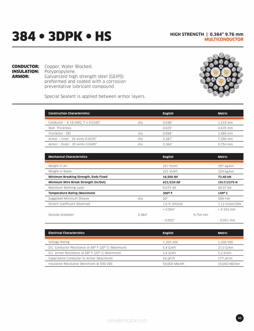
42
HIGH STRENGTH | 0.384” 9.76 mmMULTICONDUCTOR
CONDUCTOR:INSULATION:ARMOR:
Copper, Water Blocked.Polypropylene.Galvanized high strength steel (GEIPS)preformed and coated with a corrosionpreventative lubricant compound.
Special Sealant is applied between armor layers.
384 l 3DPK l HS
Construction Characteristics
Conductor – # 18 AWG, 7 x 0.0160”
Wall Thickness:
Insulation - OD:
Armor – Inner: 16 wires 0.0435”
Armor – Outer: 20 wires 0.0485”
English
0.048”
0.025”
0.098”
0.287”
0.384”
Metric
1.219 mm
0.635 mm
2.489 mm
7.290 mm
9.754 mm
dia.
dia.
dia.
dia.
Electrical Characteristics
Voltage Rating
D.C. Conductor Resistance at 68º F (20º C) (Maximum)
D.C. Armor Resistance at 68º F (20º C) (Maximum)
Capacitance Conductor to Armor (Maximum)
Insulation Resistance (Minimum) @ 500 VDC
English
1,200 VDC
6.4 Ω/kft
1.6 Ω/kft
54 pF/ft
50,000 MΩ/kft
Metric
1,200 VDC
21.0 Ω/km
5.2 Ω/km
177 pF/m
15,000 MΩ/km
dia.
0.384” 9.754 mm
Mechanical Characteristics
Weight in Air
Weight in Water
Minimum Breaking Strength, Ends Fixed
Minimum Wire Break Strength (In/Out)
Maximum Working Load
Temperature Rating (Maximum)
Suggested Minimum Sheave
Stretch Coefficient (Nominal)
Outside Diameter
English
267 lb/kft
221 lb/kft
16,500 lbf
431/534 lbf
9,075 lbf
300º F
20”
1.0 ft /kft/klb
+ 0.004”
- 0.002”
Metric
397 kg/km
329 kg/km
73.40 kN
1917/2375 N
40.37 kN
149º C
508 mm
1.12 m/km/5kN
+ 0.102 mm
- 0.051 mm

43
HIGH STRENGTH | 0.384” 9.76 mmMULTICONDUCTOR
CONDUCTOR:INSULATION:ARMOR:
Copper, Water Blocked.ETFE.Galvanized high strength steel (GEIPS)preformed and coated with a corrosionpreventative lubricant compound.
Special Sealant is applied between armor layers.
384 l 3DTK l HS
Construction Characteristics
Conductor – # 18 AWG, 7 x 0.0160”
Wall Thickness:
Insulation - OD:
Armor – Inner: 16 wires 0.0435”
Armor – Outer: 20 wires 0.0485”
English
0.048”
0.025”
0.098”
0.287”
0.384”
Metric
1.219 mm
0.635 mm
2.489 mm
7.290 mm
9.754 mm
dia.
dia.
dia.
dia.
Electrical Characteristics
Voltage Rating
D.C. Conductor Resistance at 68º F (20º C) (Maximum)
D.C. Armor Resistance at 68º F (20º C) (Maximum)
Capacitance Conductor to Armor (Maximum)
Insulation Resistance (Minimum) @ 500 VDC
English
1,200 VDC
6.4 Ω/kft
1.6 Ω/kft
60 pF/ft
50,000 MΩ/kft
Metric
1,200 VDC
21.0 Ω/km
5.2 Ω/km
197 pF/m
15,000 MΩ/km
dia.
0.384” 9.754 mm
Mechanical Characteristics
Weight in Air
Weight in Water
Minimum Breaking Strength, Ends Fixed
Minimum Wire Break Strength (In/Out)
Maximum Working Load
Temperature Rating (Maximum)
Suggested Minimum Sheave
Stretch Coefficient (Nominal)
Outside Diameter
English
267 lb/kft
221 lb/kft
16,500 lbf
431/534 lbf
9,075 lbf
500º F
20”
1.0 ft /kft/klb
+ 0.004”
- 0.002”
Metric
397 kg/km
329 kg/km
73.40 kN
1917/2375 N
40.37 kN
260º C
508 mm
1.12 m/km/5kN
+ 0.102 mm
- 0.051 mm

44
7/16” 10.82 mmMULTICONDUCTOR
CONDUCTOR:INSULATION:ARMOR:
Copper, Water Blocked.Polypropylene.Galvanized high strength steel (GEIPS)preformed and coated with a corrosionpreventative lubricant compound.
Special Sealant is applied between armor layers.
426 l 7SPK l HS
Construction Characteristics
Conductor – # 20 AWG, 7 x 0.0128”
Wall Thickness:
Insulation - OD:
Armor – Inner: 18 wires 0.0425”
Armor – Outer: 18 wires 0.059”
English
0.038”
0.018”
0.074”
0.308”
0.426”
Metric
0.965 mm
0.457 mm
1.880 mm
7.823 mm
10.820 mm
dia.
dia.
dia.
dia.
Electrical Characteristics
Voltage Rating
D.C. Conductor Resistance at 68º F (20º C) (Maximum)
D.C. Armor Resistance at 68º F (20º C) (Maximum)
Capacitance Conductor to Armor (Maximum)
Insulation Resistance (Minimum) @ 500 VDC
English
1,000 VDC
9.8 Ω/kft
1.3 Ω/kft
58 pF/ft
50,000 MΩ/kft
Metric
1,000 VDC
32.2 Ω/km
4.3 Ω/km
190 pF/m
15,000 MΩ/km
dia.
0.426” 10.82 mm
Mechanical Characteristics
Weight in Air
Weight in Water
Minimum Breaking Strength, Ends Fixed
Minimum Wire Break Strength (In/Out)
Maximum Working Load
Temperature Rating (Maximum)
Suggested Minimum Sheave
Stretch Coefficient (Nominal)
Outside Diameter
English
310 lb/kft
255 lb/kft
20,000 lbf
415/780 lbf
11,000 lbf
300º F
24”
0.70 ft /kft/klb
+ 0.005”
- 0.002”
Metric
461 kg/km
379 kg/km
88.96 kN
1846/3470 N
48.93 kN
149º C
610 mm
0.80 m/km/5kN
+ 0.127 mm
- 0.051 mm
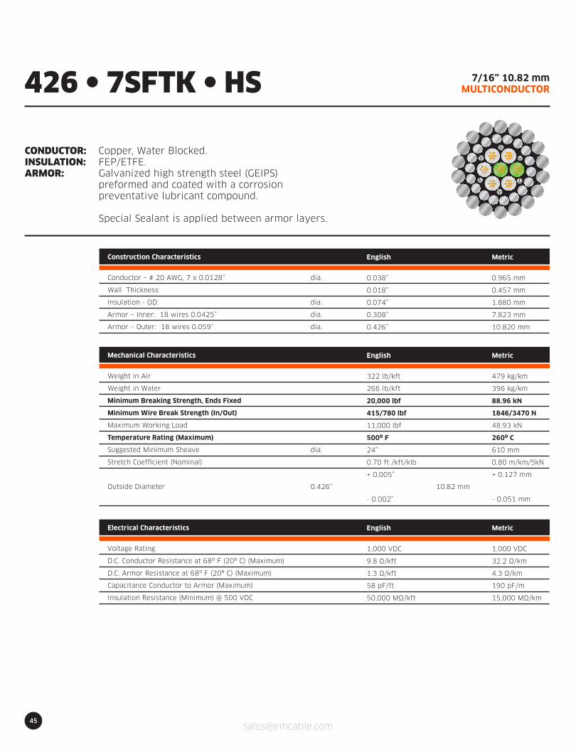
45
7/16” 10.82 mmMULTICONDUCTOR
CONDUCTOR:INSULATION:ARMOR:
Copper, Water Blocked.FEP/ETFE.Galvanized high strength steel (GEIPS)preformed and coated with a corrosionpreventative lubricant compound.
Special Sealant is applied between armor layers.
426 l 7SFTK l HS
Construction Characteristics
Conductor – # 20 AWG, 7 x 0.0128”
Wall Thickness:
Insulation - OD:
Armor – Inner: 18 wires 0.0425”
Armor – Outer: 18 wires 0.059”
English
0.038”
0.018”
0.074”
0.308”
0.426”
Metric
0.965 mm
0.457 mm
1.880 mm
7.823 mm
10.820 mm
dia.
dia.
dia.
dia.
Electrical Characteristics
Voltage Rating
D.C. Conductor Resistance at 68º F (20º C) (Maximum)
D.C. Armor Resistance at 68º F (20º C) (Maximum)
Capacitance Conductor to Armor (Maximum)
Insulation Resistance (Minimum) @ 500 VDC
English
1,000 VDC
9.8 Ω/kft
1.3 Ω/kft
58 pF/ft
50,000 MΩ/kft
Metric
1,000 VDC
32.2 Ω/km
4.3 Ω/km
190 pF/m
15,000 MΩ/km
dia.
0.426” 10.82 mm
Mechanical Characteristics
Weight in Air
Weight in Water
Minimum Breaking Strength, Ends Fixed
Minimum Wire Break Strength (In/Out)
Maximum Working Load
Temperature Rating (Maximum)
Suggested Minimum Sheave
Stretch Coefficient (Nominal)
Outside Diameter
English
322 lb/kft
266 lb/kft
20,000 lbf
415/780 lbf
11,000 lbf
500º F
24”
0.70 ft /kft/klb
+ 0.005”
- 0.002”
Metric
479 kg/km
396 kg/km
88.96 kN
1846/3470 N
48.93 kN
260º C
610 mm
0.80 m/km/5kN
+ 0.127 mm
- 0.051 mm
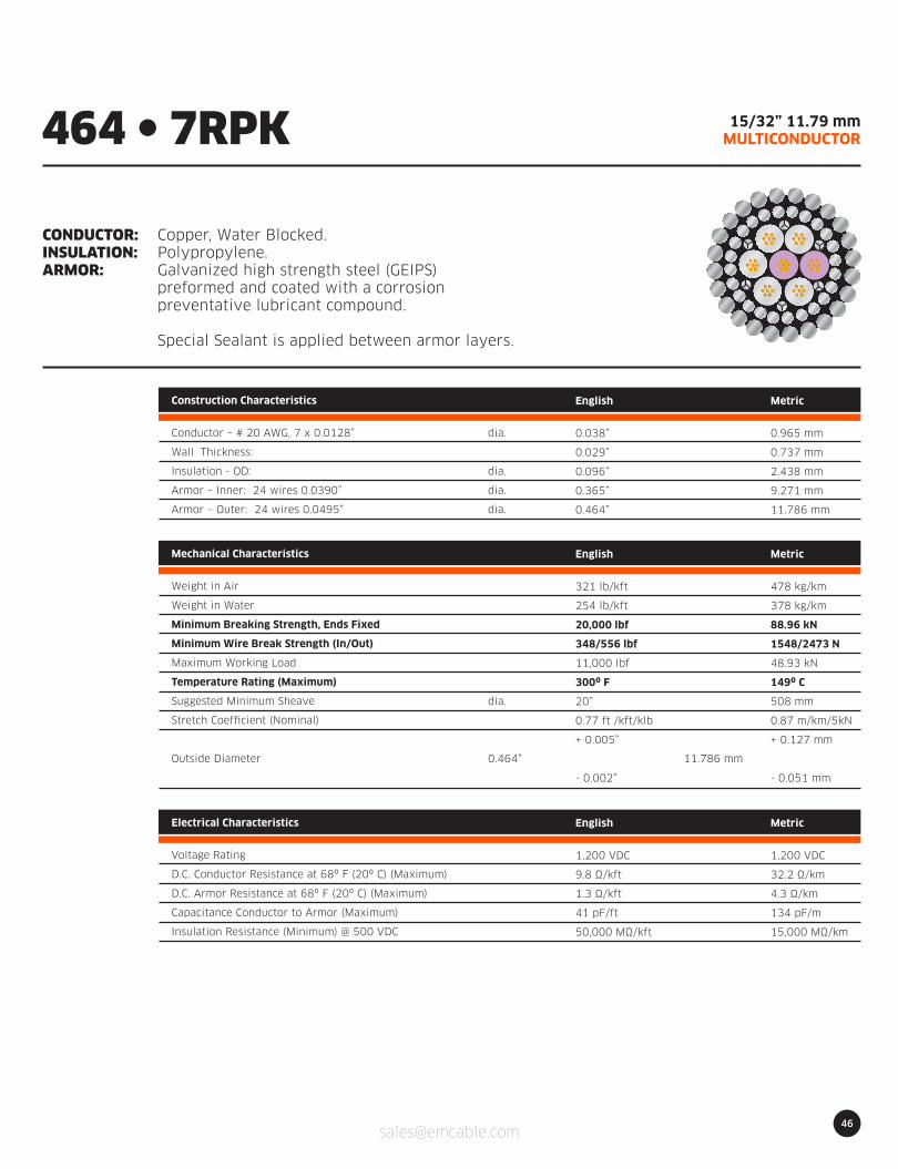
46
15/32” 11.79 mmMULTICONDUCTOR
CONDUCTOR:INSULATION:ARMOR:
Copper, Water Blocked.Polypropylene.Galvanized high strength steel (GEIPS)preformed and coated with a corrosionpreventative lubricant compound.
Special Sealant is applied between armor layers.
464 l 7RPK
Construction Characteristics
Conductor – # 20 AWG, 7 x 0.0128”
Wall Thickness:
Insulation - OD:
Armor – Inner: 24 wires 0.0390”
Armor – Outer: 24 wires 0.0495”
English
0.038”
0.029”
0.096”
0.365”
0.464”
Metric
0.965 mm
0.737 mm
2.438 mm
9.271 mm
11.786 mm
dia.
dia.
dia.
dia.
Electrical Characteristics
Voltage Rating
D.C. Conductor Resistance at 68º F (20º C) (Maximum)
D.C. Armor Resistance at 68º F (20º C) (Maximum)
Capacitance Conductor to Armor (Maximum)
Insulation Resistance (Minimum) @ 500 VDC
English
1,200 VDC
9.8 Ω/kft
1.3 Ω/kft
41 pF/ft
50,000 MΩ/kft
Metric
1,200 VDC
32.2 Ω/km
4.3 Ω/km
134 pF/m
15,000 MΩ/km
dia.
0.464” 11.786 mm
Mechanical Characteristics
Weight in Air
Weight in Water
Minimum Breaking Strength, Ends Fixed
Minimum Wire Break Strength (In/Out)
Maximum Working Load
Temperature Rating (Maximum)
Suggested Minimum Sheave
Stretch Coefficient (Nominal)
Outside Diameter
English
321 lb/kft
254 lb/kft
20,000 lbf
348/556 lbf
11,000 lbf
300º F
20”
0.77 ft /kft/klb
+ 0.005”
- 0.002”
Metric
478 kg/km
378 kg/km
88.96 kN
1548/2473 N
48.93 kN
149º C
508 mm
0.87 m/km/5kN
+ 0.127 mm
- 0.051 mm

47
15/32” 11.79 mmMULTICONDUCTOR
CONDUCTOR:INSULATION:ARMOR:
Copper, Water Blocked.FEP/ETFE.Galvanized high strength steel (GEIPS)preformed and coated with a corrosionpreventative lubricant compound.
Special Sealant is applied between armor layers.
464 l 7RFTK
Construction Characteristics
Conductor – # 20 AWG, 7 x 0.0128”
Wall Thickness:
Insulation - OD:
Armor – Inner: 24 wires 0.0390”
Armor – Outer: 24 wires 0.0495”
English
0.038”
0.029”
0.096”
0.365”
0.464”
Metric
0.965 mm
0.737 mm
2.438 mm
9.271 mm
11.786 mm
dia.
dia.
dia.
dia.
Electrical Characteristics
Voltage Rating
D.C. Conductor Resistance at 68º F (20º C) (Maximum)
D.C. Armor Resistance at 68º F (20º C) (Maximum)
Capacitance Conductor to Armor (Maximum)
Insulation Resistance (Minimum) @ 500 VDC
English
1,200 VDC
9.8 Ω/kft
1.3 Ω/kft
42 pF/ft
50,000 MΩ/kft
Metric
1,200 VDC
32.2 Ω/km
4.3 Ω/km
138 pF/m
15,000 MΩ/km
dia.
0.464” 11.786 mm
Mechanical Characteristics
Weight in Air
Weight in Water
Minimum Breaking Strength, Ends Fixed
Minimum Wire Break Strength (In/Out)
Maximum Working Load
Temperature Rating (Maximum)
Suggested Minimum Sheave
Stretch Coefficient (Nominal)
Outside Diameter
English
341 lb/kft
274 lb/kft
20,000 lbf
348/556 lbf
11,000 lbf
500º F
20”
0.77 ft /kft/klb
+ 0.005”
- 0.002”
Metric
507 kg/km
408 kg/km
88.96 kN
1548/2473 N
48.93 kN
260º C
508 mm
0.87 m/km/5kN
+ 0.127 mm
- 0.051 mm

48
HIGH STRENGTH SLAMMER | 12.04 mmMULTICONDUCTOR
CONDUCTOR:INSULATION:ARMOR:
Copper, Water Blocked.Polypropylene.Galvanized high strength steel (GEIPS)preformed and coated with a corrosionpreventative lubricant compound.
Special Sealant is applied between armor layers.
474 l 7SPK l HS
Construction Characteristics
Conductor – # 20 AWG, 7 x 0.0128”
Wall Thickness:
Insulation Conductors - OD:
Armor – Inner: 18 wires 0.0470”
Armor – Outer: 18 wires 0.0655”
English
0.038”
0.023”
0.084”
0.343”
0.474”
Metric
0.965 mm
0.584 mm
2.134 mm
8.712 mm
12.040 mm
dia.
dia.
dia.
dia.
Electrical Characteristics
Voltage Rating
D.C. Conductor Resistance at 68º F (20º C) (Maximum)
D.C. Armor Resistance at 68º F (20º C) (Maximum)
Capacitance Conductor to Armor (Maximum)
Insulation Resistance (Minimum) @ 500 VDC
English
1,100 VDC
9.8 Ω/kft
1.1 Ω/kft
48 pF/ft
50,000 MΩ/kft
Metric
1,100 VDC
32.2 Ω/km
3.6 Ω/km
157 pF/m
15,000 MΩ/km
dia.
0.474” 12.04 mm
Mechanical Characteristics
Weight in Air
Weight in Water
Minimum Breaking Strength, Ends Fixed
Minimum Wire Break Strength (In/Out)
Maximum Working Load
Temperature Rating (Maximum)
Suggested Minimum Sheave
Stretch Coefficient (Nominal)
Outside Diameter
English
377 lb/kft
311 lb/kft
24,500 lbf
502/936 lbf
13,475 lbf
300º F
27”
0.61 ft /kft/klb
+ 0.005”
- 0.002”
Metric
561 kg/km
463 kg/km
109.0 kN
2233/4163 N
59.94 kN
149º C
686 mm
0.69 m/km/5kN
+ 0.127 mm
- 0.051 mm
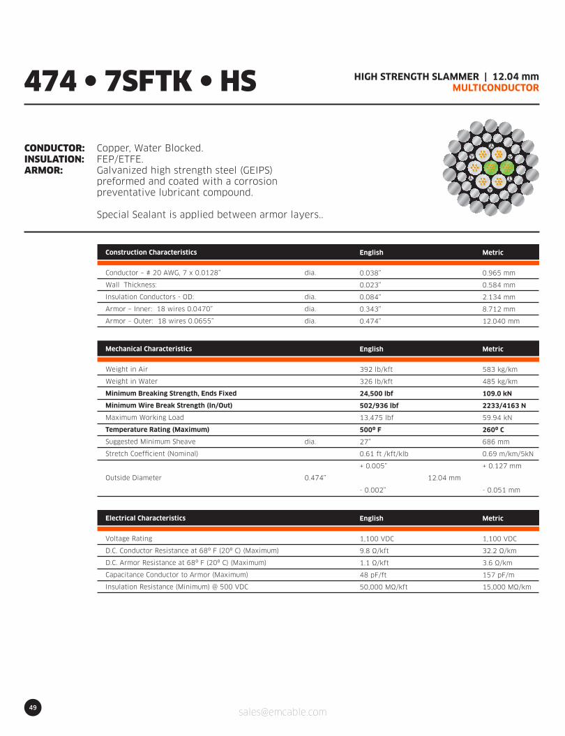
49
HIGH STRENGTH SLAMMER | 12.04 mmMULTICONDUCTOR
CONDUCTOR:INSULATION:ARMOR:
Copper, Water Blocked.FEP/ETFE.Galvanized high strength steel (GEIPS)preformed and coated with a corrosionpreventative lubricant compound.
Special Sealant is applied between armor layers..
474 l 7SFTK l HS
Construction Characteristics
Conductor – # 20 AWG, 7 x 0.0128”
Wall Thickness:
Insulation Conductors - OD:
Armor – Inner: 18 wires 0.0470”
Armor – Outer: 18 wires 0.0655”
English
0.038”
0.023”
0.084”
0.343”
0.474”
Metric
0.965 mm
0.584 mm
2.134 mm
8.712 mm
12.040 mm
dia.
dia.
dia.
dia.
Electrical Characteristics
Voltage Rating
D.C. Conductor Resistance at 68º F (20º C) (Maximum)
D.C. Armor Resistance at 68º F (20º C) (Maximum)
Capacitance Conductor to Armor (Maximum)
Insulation Resistance (Minimum) @ 500 VDC
English
1,100 VDC
9.8 Ω/kft
1.1 Ω/kft
48 pF/ft
50,000 MΩ/kft
Metric
1,100 VDC
32.2 Ω/km
3.6 Ω/km
157 pF/m
15,000 MΩ/km
dia.
0.474” 12.04 mm
Mechanical Characteristics
Weight in Air
Weight in Water
Minimum Breaking Strength, Ends Fixed
Minimum Wire Break Strength (In/Out)
Maximum Working Load
Temperature Rating (Maximum)
Suggested Minimum Sheave
Stretch Coefficient (Nominal)
Outside Diameter
English
392 lb/kft
326 lb/kft
24,500 lbf
502/936 lbf
13,475 lbf
500º F
27”
0.61 ft /kft/klb
+ 0.005”
- 0.002”
Metric
583 kg/km
485 kg/km
109.0 kN
2233/4163 N
59.94 kN
260º C
686 mm
0.69 m/km/5kN
+ 0.127 mm
- 0.051 mm

50
HIGH STRENGTH SLAMMER | 12.30 mmMULTICONDUCTOR
CONDUCTOR:INSULATION:ARMOR:
Copper, Water Blocked.FEP/ETFE.Galvanized high strength steel (GEIPS)preformed and coated with a corrosionpreventative lubricant compound.
Special Sealant is applied between armor layers.
484 l 7DFTK l HS
Construction Characteristics
Conductor – # 20 AWG, 7 x 0.0128”
Wall Thickness:
Insulation Conductors - OD:
Armor – Inner: 16 wires 0.0535”
Armor – Outer: 18 wires 0.068”
English
0.038”
0.022”
0.082”
0.348”
0.484”
Metric
0.965 mm
0.559 mm
2.083 mm
8.839 mm
12.294 mm
dia.
dia.
dia.
dia.
Electrical Characteristics
Voltage Rating
D.C. Conductor Resistance at 68º F (20º C) (Maximum)
D.C. Armor Resistance at 68º F (20º C) (Maximum)
Capacitance Conductor to Armor (Maximum)
Insulation Resistance (Minimum) @ 500 VDC
English
1,100 VDC
9.8 Ω/kft
1.0 Ω/kft
50 pF/ft
50,000 MΩ/kft
Metric
1,100 VDC
32.2 Ω/km
3.3 Ω/km
164 pF/m
15,000 MΩ/km
dia.
0.484” 12.294 mm
Mechanical Characteristics
Weight in Air
Weight in Water
Minimum Breaking Strength, Ends Fixed
Minimum Wire Break Strength (In/Out)
Maximum Working Load
Temperature Rating (Maximum)
Suggested Minimum Sheave
Stretch Coefficient (Nominal)
Outside Diameter
English
409 lb/kft
336 lb/kft
27,600 lbf
650/1071 lbf
15,180 lbf
500º F
27”
0.61 ft /kft/klb
+ 0.006”
- 0.003”
Metric
609 kg/km
500 kg/km
122.77 kN
2891/4764 N
67.52 kN
260º C
686 mm
0.69 m/km/5kN
+ 0.152 mm
- 0.076 mm

HIGH STRENGTH SLAMMER | 0.490" 12.45 mmMULTICONDUCTOR
CONDUCTOR:INSULATION:ARMOR:
Copper, Water Blocked.FEP/ETFE.Galvanized high strength steel (GEIPS)preformed and coated with a corrosionpreventative lubricant compound.
Special Sealant is applied between armor layers.Special Jacket is applied for drum crash protection.
51
490 l 7DFTK l HS
Construction Characteristics
Conductor – # 20 AWG, 7 x 0.0128”
Wall Thickness:
Insulation Conductors FEP/ETFE
Insulation Jacket ETFE
Armor – Inner: 20 wires 0.046”
Armor – Outer: 20 wires 0.062”
English
0.038”
0.023”
0.084”
0.295”
0.366”
0.490”
Metric
0.965 mm
0.584 mm
2.134 mm
7.493 mm
9.296 mm
12.446 mm
dia.
dia.
dia.
dia.
dia.
Electrical Characteristics
Voltage Rating
D.C. Conductor Resistance at 68º F (20º C) (Maximum)
D.C. Armor Resistance at 68º F (20º C) (Maximum)
Capacitance Conductor to Armor (Maximum)
Insulation Resistance (Minimum) @ 500 VDC
English
1,200 VDC
9.8Ω/kft
1.1Ω/kft
48 pF/ft
50,000 MΩ/kft
Metric
1,200 VDC
32.2Ω/km
3.6Ω/km
157 pF/m
15,000 MΩ/km
dia.
0.490” 12.45 mm
Mechanical Characteristics
Weight in Air
Weight in Water
Minimum Breaking Strength, Ends Fixed
Minimum Wire Break Strength (In/Out)
Maximum Working Load
Temperature Rating (Maximum)
Suggested Minimum Sheave
Stretch Coefficient (Nominal)
Outside Diameter
English
405 lb/kft
325 lb/kft
26,000 lbf
485/870 lbf
14,300 lbf
500º F
25”
0.60 ft /kft/klb
+ 0.005”
- 0.002”
Metric
602 kg/km
483 kg/km
115.65 kN
2157/3870 N
63.61 kN
260º C
635 mm
0.67 m/km/5kN
+ 0.127 mm
- 0.051 mm
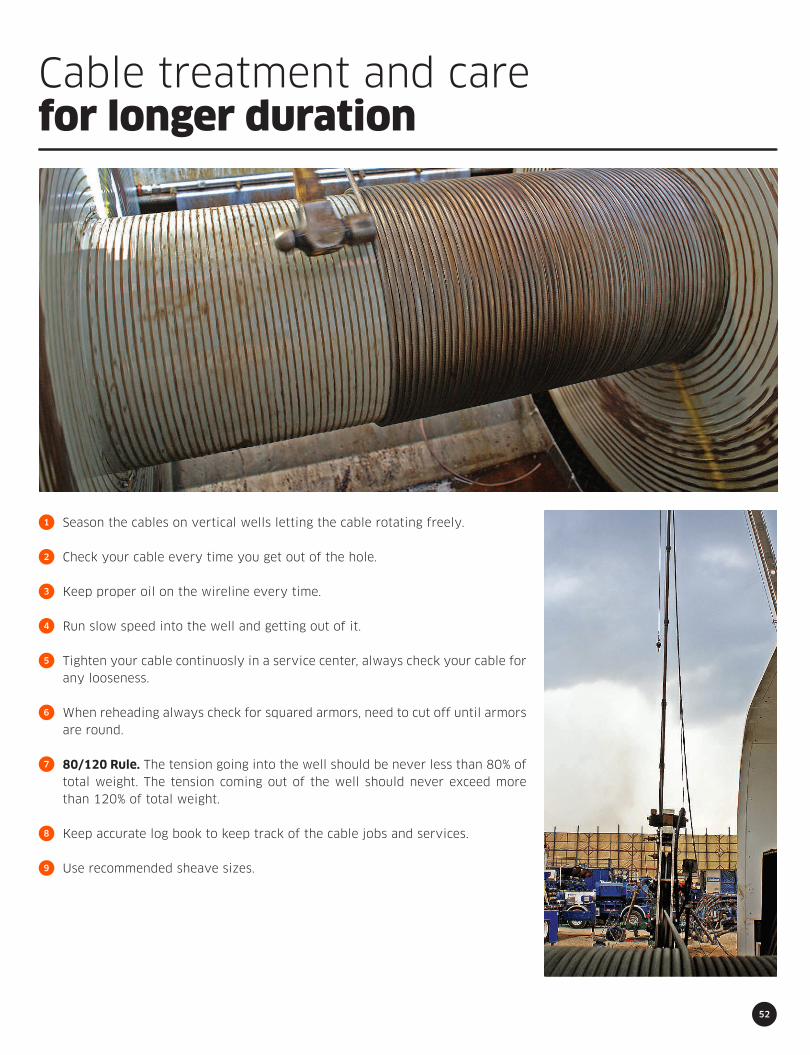
Cable treatment and carefor longer duration
52
1
2
3
4
5
6
7
8
9
Season the cables on vertical wells letting the cable rotating freely.
Check your cable every time you get out of the hole.
Keep proper oil on the wireline every time.
Run slow speed into the well and getting out of it.
Tighten your cable continuosly in a service center, always check your cable for any looseness.
When reheading always check for squared armors, need to cut off until armors are round.
80/120 Rule. The tension going into the well should be never less than 80% of total weight. The tension coming out of the well should never exceed more than 120% of total weight.
Keep accurate log book to keep track of the cable jobs and services.
Use recommended sheave sizes.

53
PRODUCED PER API 9A SPECIFICATIONS
SwablineWell service line
CABLE SPECIFICATIONCONSTRUCTION 1X16
Nominal Diameter
Construction
Inner Lay Direction
Outer Lay Direction
Final Diameter
Inner Diameter
Lay Lenght
Central Wire Diameter
Internal Wires Diameter
External Wires Diameter
Breaking Strength (klbs)
Max. Suggested Working Tension (klbs)
Weight (kg/mt)
Weight (lb/ft)
Stretch Coeficient (ft/ktf/klb)
3/16”
1 x 16
(9/6/1)
Left
Right
0.188”
-0 + 2 %
0.100”
1.080”
0.036”
Drawn Galv. IPS
0.032”
Drawn Galv. IPS
0.047”
Drawn Galv. IPS
4.50
2.25
0.112
0.075
2.34
7/32”
1 x 16
(9/6/1)
Left
Right
0.219”
-0 + 2 %
0.118”
1.274”
0.042”
Drawn Galv. IPS
0.038”
Drawn Galv. IPS
0.054”
Drawn Galv. IPS
6.00
3.00
0.146
0.098
1.80
1/4”
1 x 16
(9/6/1)
Left
Right
0.250”
-0 + 2 %
0.130”
1.040”
0.046”
Drawn Galv. IPS
0.042”
Drawn Galv. IPS
0.062”
Drawn Galv. IPS
7.30
3.65
0.198
0.133
1.35
5/16”
1 x 16
(9/6/1)
Left
Right
0.313”
-0 + 2 %
0.160”
1.28”
0.056”
Drawn Galv. IPS
0.052”
Drawn Galv. IPS
0.078”
Drawn Galv. IPS
11.34
5.67
0.311
0.209
0.86
INNER ARMOR CHARACTERISTICS
MECHANICAL CHARACTERISTICS
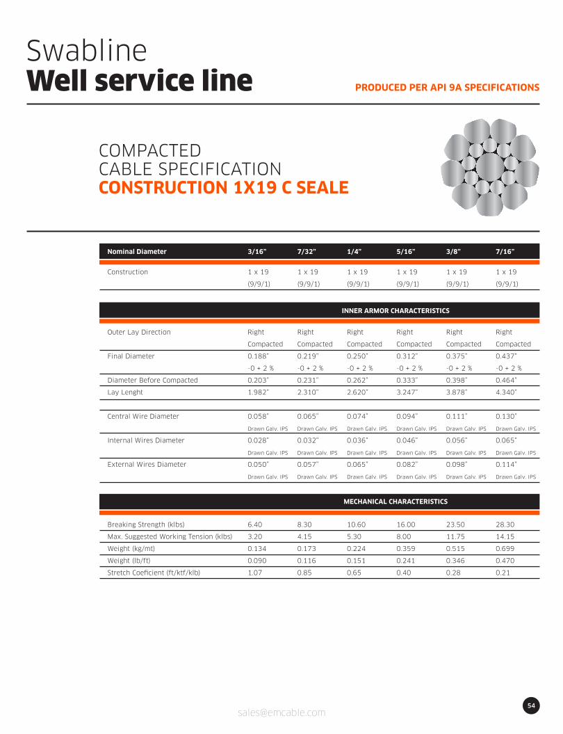
54
PRODUCED PER API 9A SPECIFICATIONS
SwablineWell service line
COMPACTEDCABLE SPECIFICATIONCONSTRUCTION 1X19 C SEALE
Nominal Diameter
Construction
Outer Lay Direction
Final Diameter
Diameter Before Compacted
Lay Lenght
Central Wire Diameter
Internal Wires Diameter
External Wires Diameter
Breaking Strength (klbs)
Max. Suggested Working Tension (klbs)
Weight (kg/mt)
Weight (lb/ft)
Stretch Coeficient (ft/ktf/klb)
3/16”
1 x 19
(9/9/1)
Right
Compacted
0.188”
-0 + 2 %
0.203”
1.982”
0.058”
Drawn Galv. IPS
0.028”
Drawn Galv. IPS
0.050”
Drawn Galv. IPS
6.40
3.20
0.134
0.090
1.07
7/32”
1 x 19
(9/9/1)
Right
Compacted
0.219”
-0 + 2 %
0.231”
2.310”
0.065”
Drawn Galv. IPS
0.032”
Drawn Galv. IPS
0.057”
Drawn Galv. IPS
8.30
4.15
0.173
0.116
0.85
1/4”
1 x 19
(9/9/1)
Right
Compacted
0.250”
-0 + 2 %
0.262”
2.620”
0.074”
Drawn Galv. IPS
0.036”
Drawn Galv. IPS
0.065”
Drawn Galv. IPS
10.60
5.30
0.224
0.151
0.65
5/16”
1 x 19
(9/9/1)
Right
Compacted
0.312”
-0 + 2 %
0.333”
3.247”
0.094”
Drawn Galv. IPS
0.046”
Drawn Galv. IPS
0.082”
Drawn Galv. IPS
16.00
8.00
0.359
0.241
0.40
3/8”
1 x 19
(9/9/1)
Right
Compacted
0.375”
-0 + 2 %
0.398”
3.878”
0.111”
Drawn Galv. IPS
0.056”
Drawn Galv. IPS
0.098”
Drawn Galv. IPS
23.50
11.75
0.515
0.346
0.28
7/16”
1 x 19
(9/9/1)
Right
Compacted
0.437”
-0 + 2 %
0.464”
4.340”
0.130”
Drawn Galv. IPS
0.065”
Drawn Galv. IPS
0.114”
Drawn Galv. IPS
28.30
14.15
0.699
0.470
0.21
INNER ARMOR CHARACTERISTICS
MECHANICAL CHARACTERISTICS
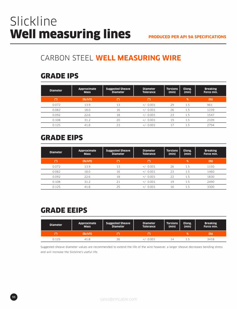
55
PRODUCED PER API 9A SPECIFICATIONS
SlicklineWell measuring lines
CARBON STEEL WELL MEASURING WIRE
0.072
0.082
0.092
0.108
0.125
Diameter
13.9
18.0
22.6
31.2
41.8
ApproximateMass
(lb/kft)(”)
13
16
18
20
23
(”)
Suggested SheaveDiameter
961
1239
1547
2109
2794
(lb)
BreakingForce min.
+/- 0.001
+/- 0.001
+/- 0.001
+/- 0.001
+/- 0.001
DiameterTolerance
29
26
23
19
17
Torsions(min)
(”)
1.5
1.5
1.5
1.5
1.5
Elong.(min)
%
GRADE IPS
0.072
0.082
0.092
0.108
0.125
Diameter
13.9
18.0
22.6
31.2
41.8
ApproximateMass
(lb/kft)(”)
13
16
18
21
25
(”)
Suggested SheaveDiameter
1150
1460
1830
2490
3300
(lb)
BreakingForce min.
+/- 0.001
+/- 0.001
+/- 0.001
+/- 0.001
+/- 0.001
DiameterTolerance
26
23
22
19
16
Torsions(min)
(”)
1.5
1.5
1.5
1.5
1.5
Elong.(min)
%
GRADE EIPS
0.125
Diameter
41.8
ApproximateMass
(lb/kft)(”)
26
(”)
Suggested SheaveDiameter
3418
(lb)
BreakingForce min.
+/- 0.001
DiameterTolerance
14
Torsions(min)
(”)
1.5
Elong.(min)
%
GRADE EEIPS
Suggested sheave diameter values are recommended to extend the life of the wire however, a larger sheave decreases bending stress
and will increase the Slickline’s useful life.
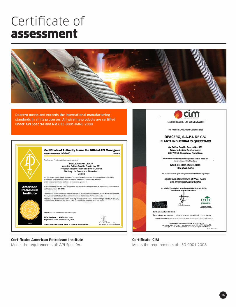
56
Certificate: CIMMeets the requirements of: ISO 9001:2008
Certificate: American Petroleum InstituteMeets the requirements of: API Spec 9A
56
Certificate ofassessment
Deacero meets and exceeds the international manufacturing
standards in all its processes. All wireline products are certified
under API Spec 9A and NMX-CC-9001-IMNC-2008.

57
Warranty
Deacero warrants that all of its electromechanical cable purchased from an authori-zed dealer or contractor will be free from defects in materials or workmanship. Deacero also guarantees that all of its electromechanical cable will meet published breaking strengths and electrical characteristics.
The Purchaser has the obligation to indicate the environmental conditions under which the cable will be used so the authorized dealer or contractor can supply the correspondent electromechanical cable. Failure to do so will cancel this warranty.
This warranty is given by Deacero subject to the following conditions:
Deacero may at its own option within a reasonable time either repair or replace the Products, or issue a Credit for any such Products in the amount of the original invoi-ce price. Seller’s obligation shall be limited solely to repair or replacement of the Products and does not include freight, removal, and installation charges. This warranty is strictly limited to the value of the product supplied.
The foregoing warranty is exclusive and in lieu of all other warranties, expressed or implied, including but not limited to, implied warranties of merchantability or fitness for particular pur-pose. In no event will Deacero be liable for any lost profits or for any direct, indirect, incidental, consequential, punitive or other special dama-ges arising out of or related to its products regardless of whether such damages are sought based on causes of action sounding in tort, contract, negligence, strict liabili-ty or breach of warranty.
Published breaking strength or electrical characteristics apply only to new, unused electro-mechanical cable, and when the mechanical equipment on which such products are used is properly designed and maintained.
The electromechanical cables must be stored, handled, used and maintained, and properly inspected from time to time during the period of use.
The products must be installed by a qualified company.
1
2
3


USA+1 832 623 4258+1 713 213 8969+1 337 277 7266
Canada+1 780 722 1595+1 832 623 4258
Colombia+57 310 275 2287+1 713 213 8969
Mexico01 800 2235 333
Worldwide Numbers+1 713 213 8969+1 832 623 4258
0817