word clock pic controller pcb construction notes clock pic controller pcb construction notes ......
TRANSCRIPT
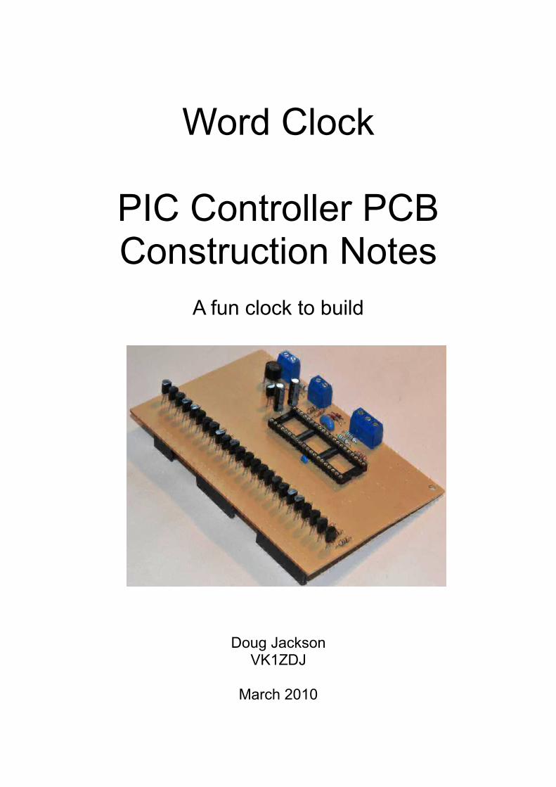
Word Clock
PIC Controller PCB Construction Notes
A fun clock to build
Doug JacksonVK1ZDJ
March 2010
Licence
The Word Clock Design, PCB layout, Manual, and Firmware is Copyright 2010, by Douglas Jackson, VK1ZDJ.
This Design, PCB layout, Manual and Firmware is licenced under the TAPR Open Hardware Licence. www.tapr.org/OHL.
Permission is granted for anybody to:
• Modify the documentation and make products based upon it.• Use the products for any legal purpose without limitation. • Distribute unmodified documentation, but you must include the complete package
as you received it. • Distribute products you make to third parties, if you either include the
documentation on which the product is based, or make it available without charge for at least three years to anyone who requests it.
• Distribute modified documentation or products based on it, if you license your modifications under the OHL.
If you do use my design to manufacture a kit, I would appreciate it if you would attempt to send the modified documentation by email to [email protected]. This is a good faith obligation -- if the email fails, you need do nothing more and may go on with your distribution.
Welcome
Thanks for deciding to make this great little clock project. You will find that this simple clock will be a centre piece for many discussions into the future, as well as providing a great way to tell the time.
Because there are so many ways to construct the clock, I have broken assembly down into various documents – this document details the construction of the microchip PIC Controller board.
You will find that construction of this clock is very simple. If you are methodical with your construction practices, and careful with you soldering, you will find that the clock almost assembles itself.
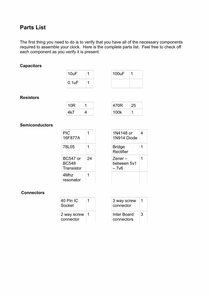
Parts List
The first thing you need to do is to verify that you have all of the necessary components required to assemble your clock. Here is the complete parts list. Feel free to check off each component as you verify it is present.
Capacitors
10uF 1 100uF 1
0.1uF 1
Resistors
10R 1 470R 254k7 4 100k 1
Semiconductors
PIC 16F877A
1 1N4148 or 1N914 Diode
4
78L05 1 Bridge Rectifier
1
BC547 or BC548 Transistor
24 Zener – between 5v1 – 7v6
1
4Mhz resonator
1
Connectors
40 Pin IC Socket
1 3 way screw connector
1
2 way screw connector
1 Inter Board connectors
3
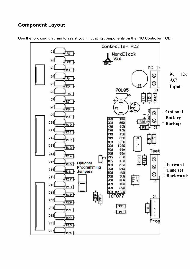
Component Layout
Use the following diagram to assist you in locating components on the PIC Controller PCB:
9v – 12v AC Input
Optional Battery Backup
ForwardTime setBackwards
-
+
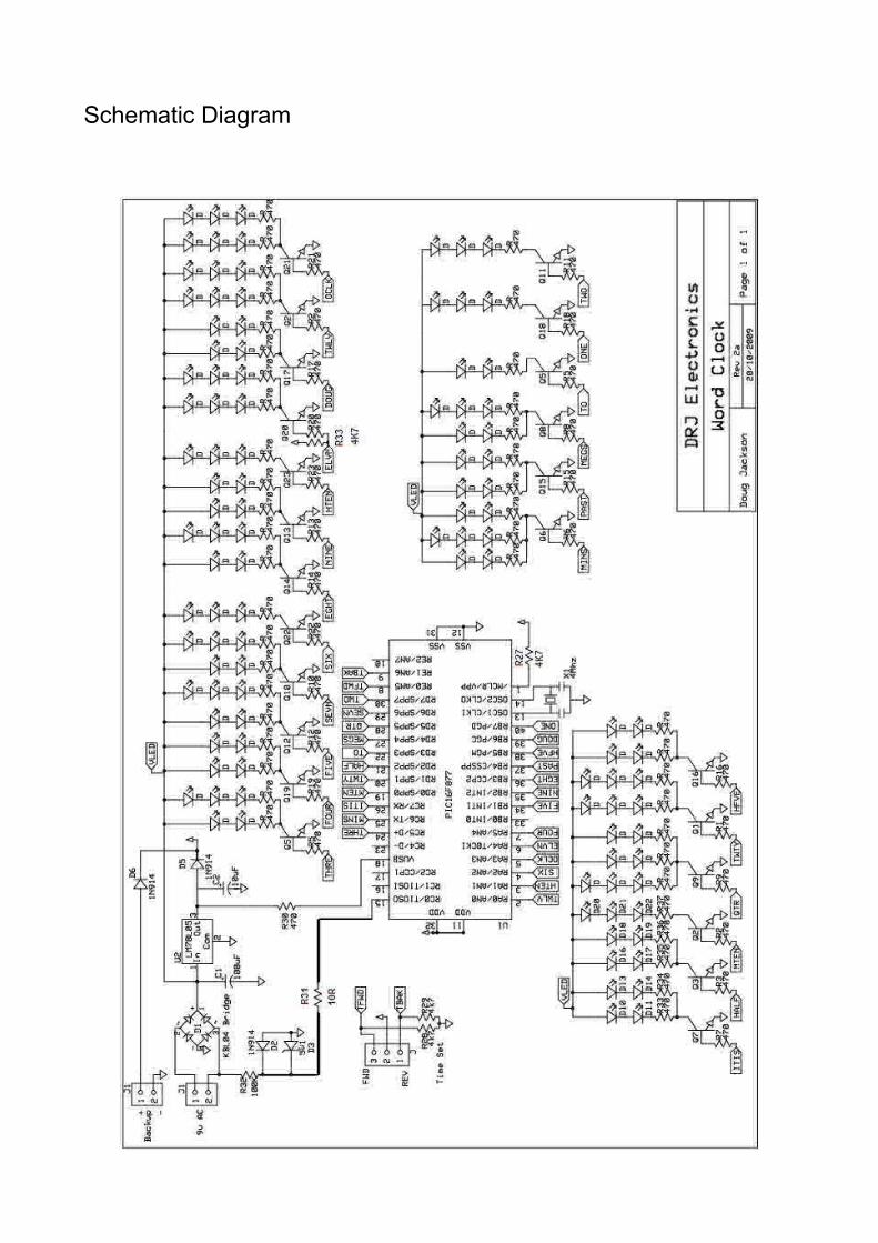
Schematic Diagram
Construction
Assembling the controller board is fairly simple. Start by examining the copper side of the PCB for any manufacturing defects – I check each board before it is sent, but a second check never goes astray.Make sure that all tracks are complete, and not shorted to adjoining tracks. If there are any small shorts, remove them gently using a sharp blade.
You may find that the protective coating that has been applied to the hand made PCB (to prevent oxidation) requires additional time to allow a proper solder bond. This is normal.
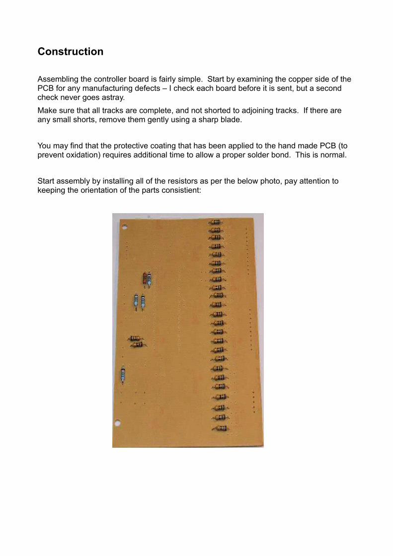
Start assembly by installing all of the resistors as per the below photo, pay attention to keeping the orientation of the parts consistient:
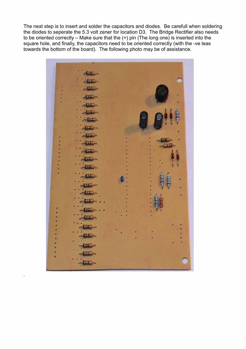
The next step is to insert and solder the capacitors and diodes. Be carefull when soldering the diodes to seperate the 5.3 volt zener for location D3. The Bridge Rectifier also needs to be oriented correctly – Make sure that the (+) pin (The long one) is inserted into the square hole, and finally, the capacitors need to be oriented correctly (with the -ve leas towards the bottom of the board). The following photo may be of assistance.
.
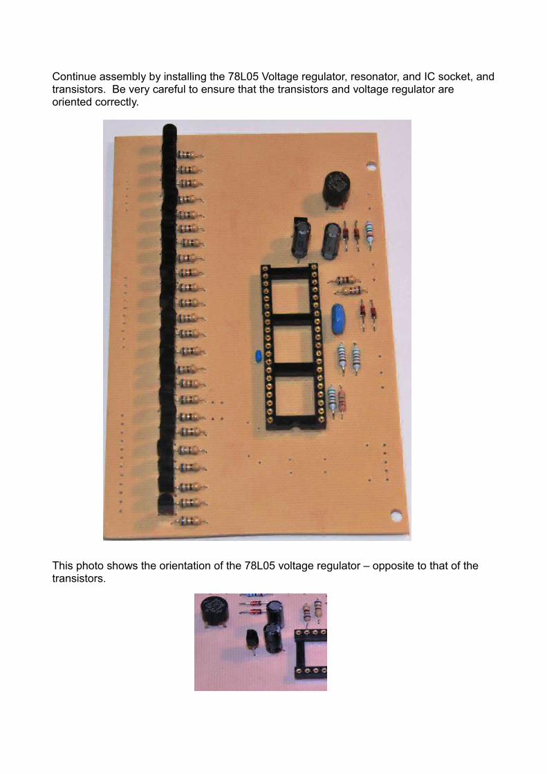
Continue assembly by installing the 78L05 Voltage regulator, resonator, and IC socket, and transistors. Be very careful to ensure that the transistors and voltage regulator are oriented correctly.
This photo shows the orientation of the 78L05 voltage regulator – opposite to that of the transistors.
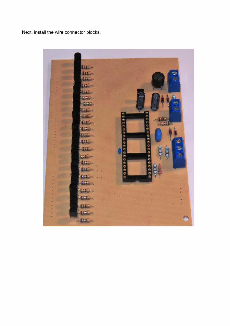
Next, install the wire connector blocks,
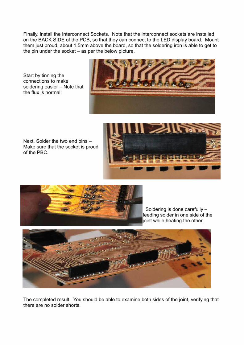
Finally, install the Interconnect Sockets. Note that the interconnect sockets are installed on the BACK SIDE of the PCB, so that they can connect to the LED display board. Mount them just proud, about 1.5mm above the board, so that the soldering iron is able to get to the pin under the socket – as per the below picture.
Start by tinning the connections to make soldering easier – Note that the flux is normal:
Next, Solder the two end pins – Make sure that the socket is proud of the PBC.
Soldering is done carefully – feeding solder in one side of the joint while heating the other.
The completed result. You should be able to examine both sides of the joint, verifying that there are no solder shorts.
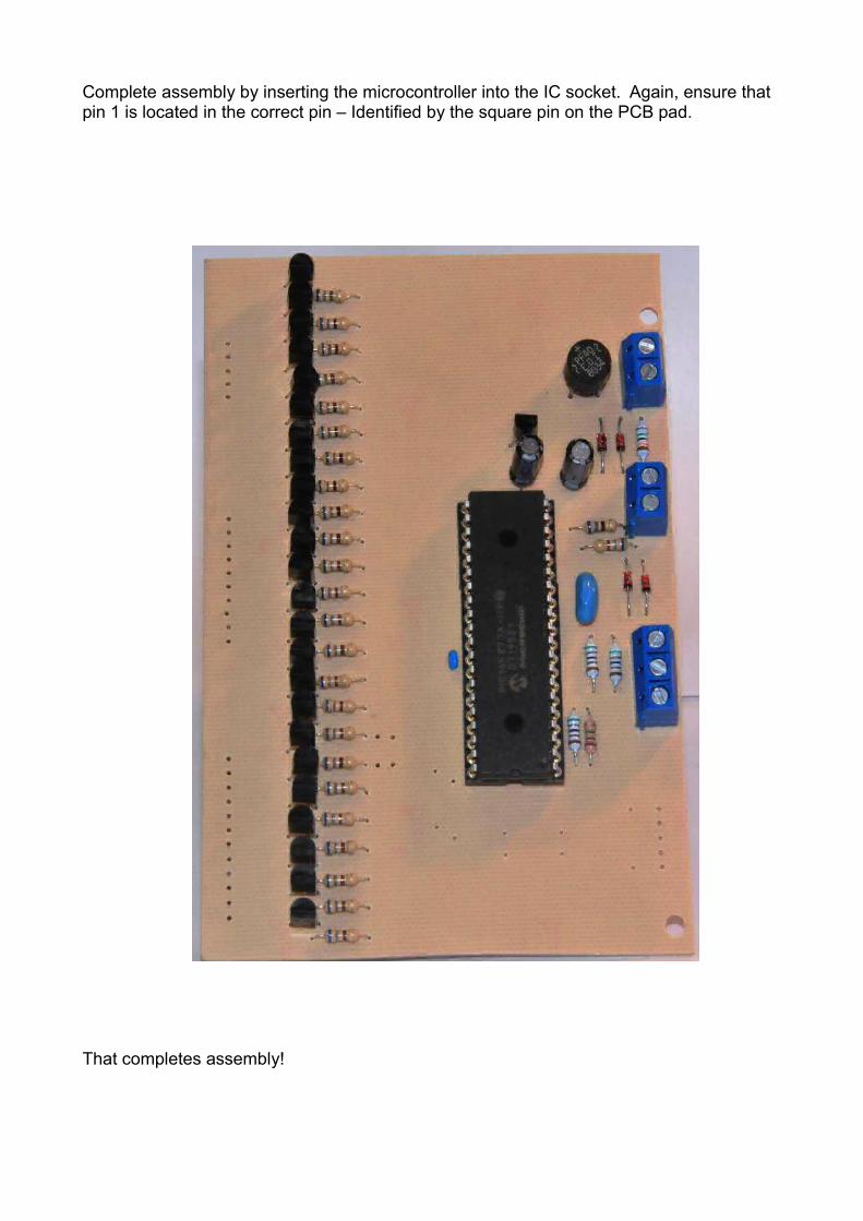
Complete assembly by inserting the microcontroller into the IC socket. Again, ensure that pin 1 is located in the correct pin – Identified by the square pin on the PCB pad.
That completes assembly!
Optional programming components
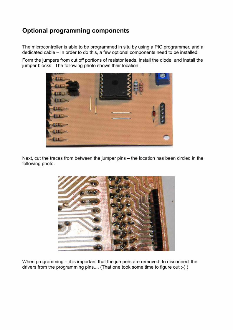
The microcontroller is able to be programmed in situ by using a PIC programmer, and a dedicated cable – In order to do this, a few optional components need to be installed.Form the jumpers from cut off portions of resistor leads, install the diode, and install the jumper blocks. The following photo shows their location.
Next, cut the traces from between the jumper pins – the location has been circled in the following photo.
When programming – it is important that the jumpers are removed, to disconnect the drivers from the programming pins.... (That one took some time to figure out ;-) )
Testing
The board is able to be tested by connecting a 12V AC supply to the power input (Header beside the Bridge Rectifier), and plugging the board onto the LED display board, and attaching the board with the supplied metal standoffs.
As soon as power is applied, the matrix should go through a full self test. Every led should illuminate in blocks of words.
If it does not, verify that the supply polarity is correct, and that the 78L05 has been installed correctly. There should be +9V on the input of the 78L05, and +5V on the output.
Time set input
The 3 pin wire connector on the board is designed to be connected to two normally open push buttons for setting the time. The centre pin is common, and the outside pins are to be connected to each time set pushbutton. One time set button increments the time, and the other decrements the time.
Programming
The Microprocessor supplied with the board has been pre-programmed before it has been sent out.If you wish, the PIC microprocessor is able to be re-programmed using any standard PIC programmer. Just remember to remove the programming jumpers – alternately, the micro can be removed from the socket, and installed into a programmer for programming.
Source code is available from the instructables.com project website.
Have fun, and I hope that you enjoy your clock as much as I do!!.
Doug Jackson