worksheet 3 deflection: 2d frames - expedition workshed · pdf fileportal frame roller-support...
TRANSCRIPT

An introduction to understanding the deflection of two-dimensional frames using the Push Me Pull Me models on Expedition Workshed
WorkshEEt 3DEflEction: 2D frAMEs
Worksheet by stylianos yiatros, brunel universityProduced With funding from the royal academy of engineering's national he stem Programme
Pg. 2Pg. 2
Worksheet by stylianos yiatros, brunel universityProduced With funding from the royal academy of engineering's national he stem Programme
introDuctionFollowing on from Worksheet 2, which looked at the deflection of beams, this worksheet focuses on the deflections of portal frames.
In these 2D examples we assume that the frames are stable in and out-of-plane and their self weight is not taken into account.
Firstly a few standard examples of frames are modelled mathematically and a few tips are given on how to sketch the deflected shape.
This is followed by practice questions, which will ask you to sketch the deflected shapes of a number of different portal frames under specific loads.
Worksheet by stylianos yiatros, brunel universityProduced With funding from the royal academy of engineering's national he stem Programme Pg. 3Pg. 3
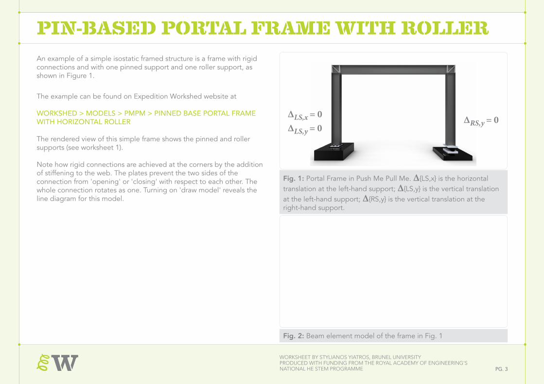
Pin-BAsED PortAl frAME With rollErAn example of a simple isostatic framed structure is a frame with rigid connections and with one pinned support and one roller support, as shown in Figure 1.
The example can be found on Expedition Workshed website at
WORKSHED > MODELS > PMPM > PINNED BASE PORTAL FRAME WITH HORIZONTAL ROLLER
The rendered view of this simple frame shows the pinned and roller supports (see worksheet 1).
Note how rigid connections are achieved at the corners by the addition of stiffening to the web. The plates prevent the two sides of the connection from 'opening' or 'closing' with respect to each other. The whole connection rotates as one. Turning on 'draw model' reveals the line diagram for this model.
Fig. 2: Beam element model of the frame in Fig. 1
Δ R S ,y = 0Δ L S ,x = 0Δ
L S ,y = 0
Fig. 1: Portal Frame in Push Me Pull Me. Δ{LS,x} is the horizontal translation at the left-hand support; Δ{LS,y} is the vertical translation at the left-hand support; Δ{RS,y} is the vertical translation at the right-hand support.
ΔLS,x = 0ΔLS,y = 0
ΔRS,y = 0

Worksheet by stylianos yiatros, brunel universityProduced With funding from the royal academy of engineering's national he stem Programme Pg. 4Pg. 4
Pin-BAsED PortAl frAME With rollErApplying a downward vertical point load anywhere along a beam (Fig. 3) will cause it to bend and curve downwards (sagging) . The columns will rotate as the right-hand support moves outwards, but the columns will nevertheless remain straight.
Applying a point load horizontally on the left hand side beam-column joint, the portal frame sways (Fig. 4). The left-hand column rotates freely at the base but it curves as you look towards the joint. The beam also bends, stretching on the underside and, as expected, the right-hand column rotates as the right support moves outwards, but remains straight.
Finally, if the load is applied horizontally at the right hand roller support, the base will move inwards, causing all elements (beam and columns) to bend, curving outwards, as seen in Fig. 5. If the point load were applied in the opposite direction, the portal frame would curve inwards as the supports spread further apart.
Fig. 4. The same model, this time with a horizontal load on a corner.
Fig. 3. Portal Frame Roller-Support Push Me Pull Me Mode with a vertical load mid-span.
Fig. 5. Again, but with the horizontal load at the base of the roller-joint support
Bent
BentBent
Straight
Straight
Worksheet by stylianos yiatros, brunel universityProduced With funding from the royal academy of engineering's national he stem Programme Pg. 5Pg. 5
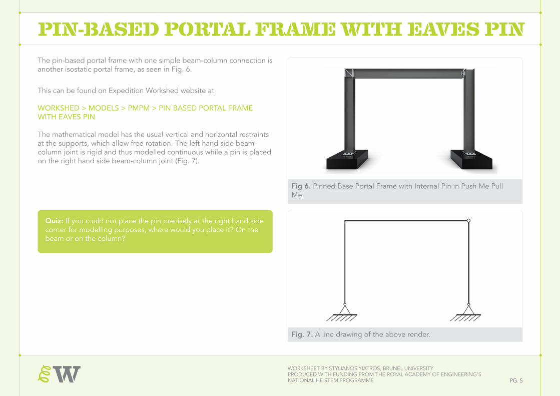
Pin-BAsED PortAl frAME With EAvEs PinThe pin-based portal frame with one simple beam-column connection is another isostatic portal frame, as seen in Fig. 6.
This can be found on Expedition Workshed website at
WORKSHED > MODELS > PMPM > PIN BASED PORTAL FRAME WITH EAVES PIN
The mathematical model has the usual vertical and horizontal restraints at the supports, which allow free rotation. The left hand side beam-column joint is rigid and thus modelled continuous while a pin is placed on the right hand side beam-column joint (Fig. 7).
Fig 6. Pinned Base Portal Frame with Internal Pin in Push Me Pull Me.
Fig. 7. A line drawing of the above render.
Quiz: If you could not place the pin precisely at the right hand side corner for modelling purposes, where would you place it? On the beam or on the column?
Worksheet by stylianos yiatros, brunel universityProduced With funding from the royal academy of engineering's national he stem Programme Pg. 6Pg. 6
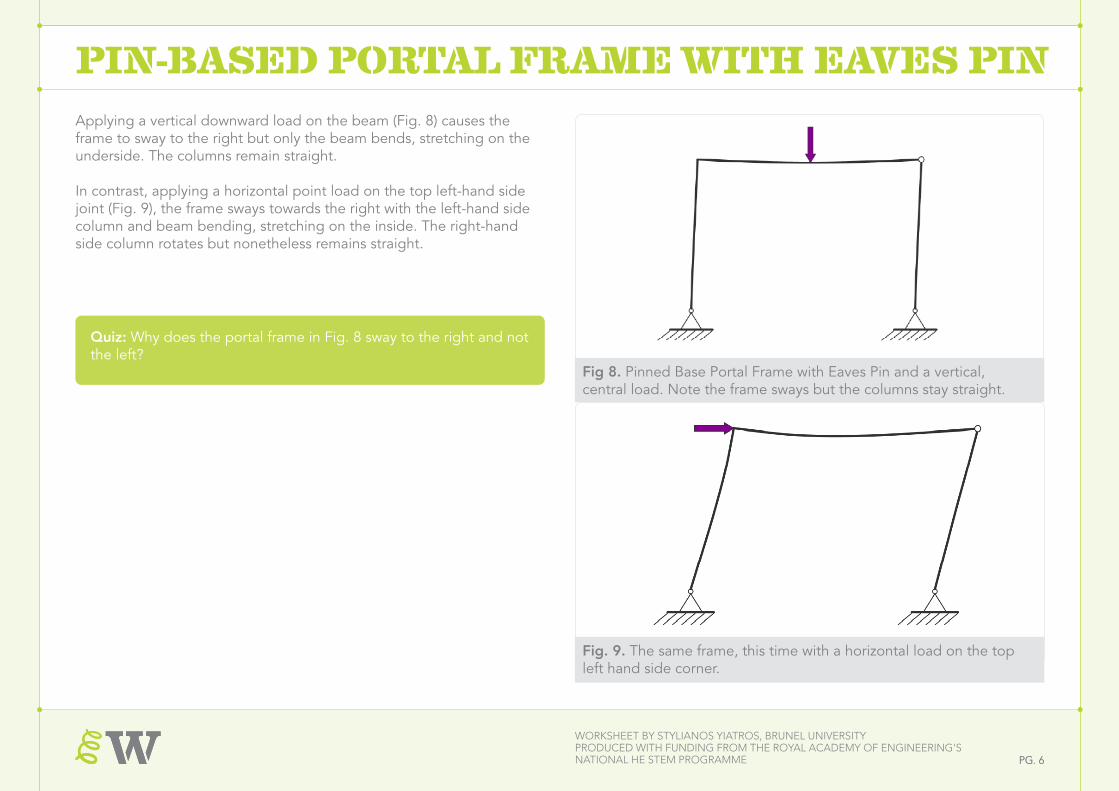
Pin-BAsED PortAl frAME With EAvEs PinApplying a vertical downward load on the beam (Fig. 8) causes the frame to sway to the right but only the beam bends, stretching on the underside. The columns remain straight.
In contrast, applying a horizontal point load on the top left-hand side joint (Fig. 9), the frame sways towards the right with the left-hand side column and beam bending, stretching on the inside. The right-hand side column rotates but nonetheless remains straight.
Fig 8. Pinned Base Portal Frame with Eaves Pin and a vertical, central load. Note the frame sways but the columns stay straight.
Fig. 9. The same frame, this time with a horizontal load on the top left hand side corner.
Quiz: Why does the portal frame in Fig. 8 sway to the right and not the left?
Worksheet by stylianos yiatros, brunel universityProduced With funding from the royal academy of engineering's national he stem Programme Pg. 7Pg. 7
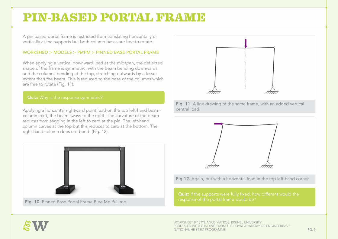
Pin-BAsED PortAl frAMEA pin based portal frame is restricted from translating horizontally or vertically at the supports but both column bases are free to rotate.
WORKSHED > MODELS > PMPM > PINNED BASE PORTAL FRAME
When applying a vertical downward load at the midspan, the deflected shape of the frame is symmetric, with the beam bending downwards and the columns bending at the top, stretching outwards by a lesser extent than the beam. This is reduced to the base of the columns which are free to rotate (Fig. 11).
Fig. 11. A line drawing of the same frame, with an added vertical central load.
Quiz: Why is the response symmetric?
Applying a horizontal rightward point load on the top left-hand beam-column joint, the beam sways to the right. The curvature of the beam reduces from sagging in the left to zero at the pin. The left-hand column curves at the top but this reduces to zero at the bottom. The right-hand column does not bend. (Fig. 12).
Quiz: If the supports were fully fixed, how different would the response of the portal frame would be?
Fig 10. Pinned Base Portal Frame in Push Me Pull Me.
Fig 12. Again, but with a horizontal load in the top left-hand corner.
Fig. 10. Pinned Base Portal Frame Puss Me Pull me.
Worksheet by stylianos yiatros, brunel universityProduced With funding from the royal academy of engineering's national he stem Programme Pg. 8Pg. 8
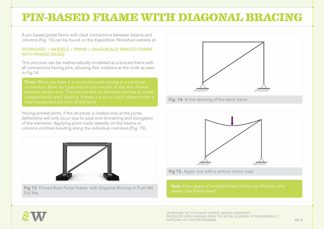
Pin-BAsED frAME With DiAgonAl BrAcingA pin based portal frame with cleat connections between beams and columns (Fig. 13) can be found on the Expedition Workshed website at
WORKSHED > MODELS > PMPM > DIAGONALLY BRACED FRAME WITH PINNED BASES.
This structure can be mathematically modelled as a braced frame with all connections having pins, allowing free rotations at the ends as seen in Fig.14.
Trivia: When you have 3 or more elements joining at a particular connection, there isn’t just one pin but one pin at the end of each member except one. This ensures that all elements are free to rotate independently upon loading. If there is a pin on each element then a local mechanism will form at that joint.
Having pinned joints, if the structure is loaded only at the joints, deflections will only occur due to axial end shortening and elongation of the elements. Applying point loads laterally on the beams or columns confines bending along the individual members (Fig. 15).
Quiz: If you apply a horizontal load on the top left joint, why doesn’t the frame sway?
Fig 13. Pinned Base Portal Frame with Diagonal Bracing in Push Me Pull Me.
Fig 15. Again, but with a vertical centre load.
Fig. 14. A line drawing of the same frame.
Worksheet by stylianos yiatros, brunel universityProduced With funding from the royal academy of engineering's national he stem Programme Pg. 9Pg. 9
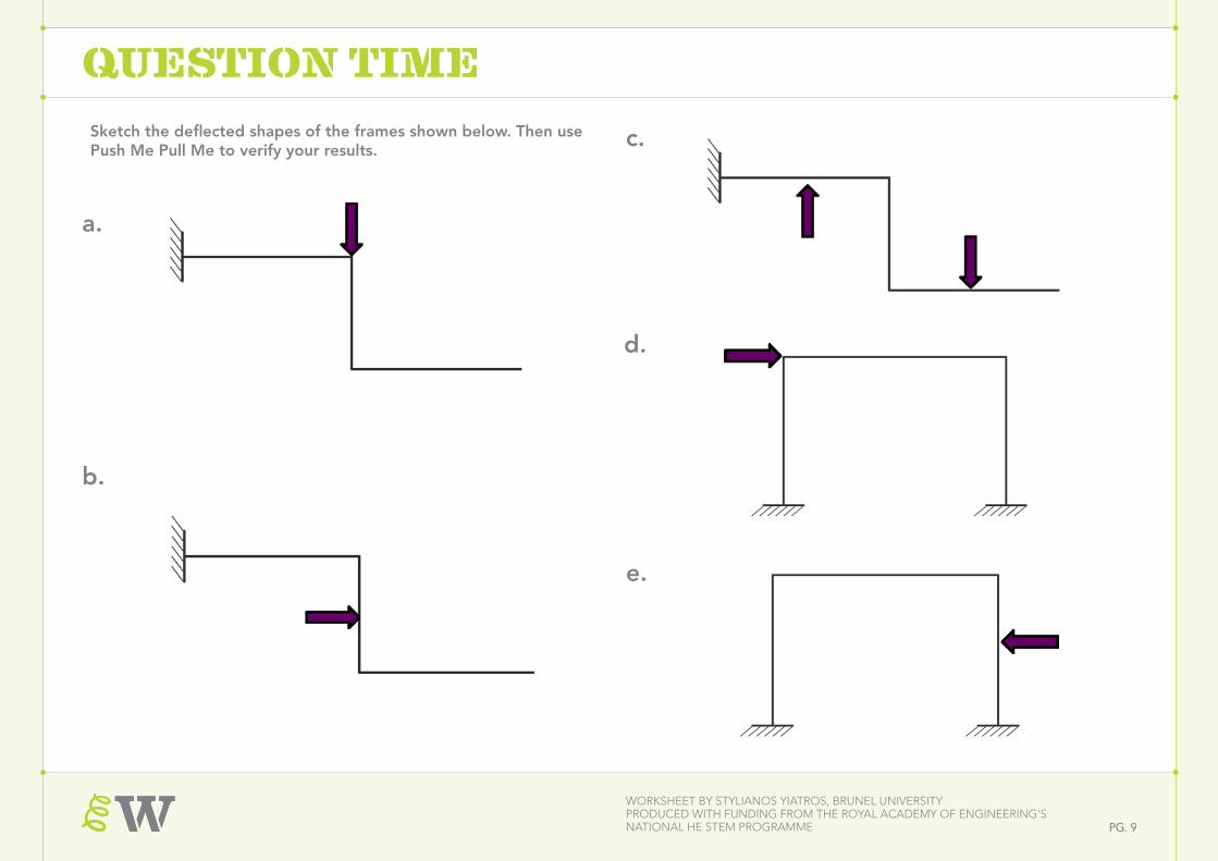
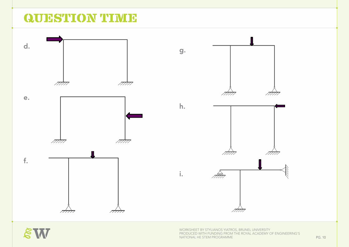
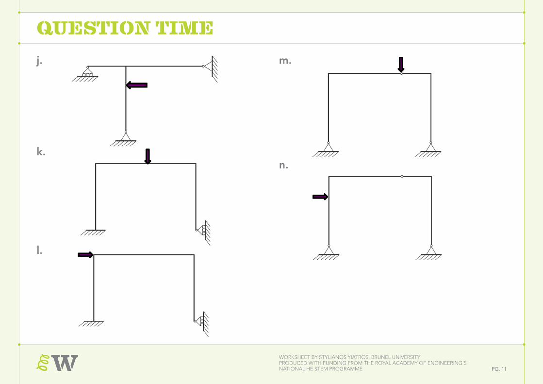
Sketch the deflected shapes of the frames shown below. Then use Push Me Pull Me to verify your results.
a.
b.
c.
d.
e.
QuEstion tiME
Worksheet by stylianos yiatros, brunel universityProduced With funding from the royal academy of engineering's national he stem Programme Pg. 10Pg. 10
d.
e.
g.
h.
i.
QuEstion tiME
f.
Worksheet by stylianos yiatros, brunel universityProduced With funding from the royal academy of engineering's national he stem Programme Pg. 11Pg. 11
j.
k.
l.
m.
n.
QuEstion tiME