wormhole ip over (connectionless) atmavani/wormhole/2001-p650-katevenis.pdf · wormhole ip over...
TRANSCRIPT

650 IEEE/ACM TRANSACTIONS ON NETWORKING, VOL. 9, NO. 5, OCTOBER 2001
Wormhole IP Over (Connectionless) ATM Manolis G. H. Katevenis, Member, IEEE, Iakovos Mavroidis, Georgios Sapountzis, Eva Kalyvianaki,
Ioannis Mavroidis, and Georgios Glykopoulos
Abstract--High-speed switches and routers internally operate using fixed-size cells or segments; variable-size packets are seg- mented and later reassembled. Connectionless ATM was proposed to quickly carry IP packets segmented into cells (AAL5) using a number of hardware-managed ATM VCs. We show that this is analogous to wormhole routing. We modify this architecture to make it applicable to existing ATM equipment: we propose a low-cost, single-input, single-output Wormhole IP Router that functions as a VP/VC translation filter between ATM subnet- works. When compared to IP routers, the proposed architecture features simpler hardware and lower latency. When compared to software-based IP-over-ATM techniques, the new architecture avoids the overheads of a large number of labels, or the delays of establishing new flows in software after the first few packets have suffered considerable latencies. We simulated a wormhole IP routing filter, showing that a few tens of hardware-managed VCs per outgoing VP usually suffice. We built and successfully tested a prototype, operating at 2 x 155 Mb/s, using one field programmable gate array (FPGA) and DRAM. Simple analysis shows that operation at 10 Gb/s and beyond is feasible today.
Index Terms--Connectionless ATM, gigabit router, IP over ATM, routing filter, wormhole IP, wormhole routing.
I. INTRODUCTION
S WITCHING hardware usually operates on fixed-size units, i called cells or segments or frames, usually in the range of 50
to 128 bytes each, especially in high-speed networking equip- ment. Fixed size cells simplify a number of hardware issues, including buffer memory and queue management and crossbar switch scheduling. A small cell size allows fast pre-emption, hence reduced latency for high-priority traffic. These observa- tions were key in the development of the Asynchronous Transfer Mode (ATM) networking technology, more than a decade ago; ATM carries all traffic in 53-byte cells (5-byte header, 48-byte payload).
Manuscript received May 12, 1999; recommended by IEEE/ACM TRANSACTIONS ON NETWORKING Editor G. Parulkar. This work was supported by the Institute of Computer Science of the Foundation for Research and Technology-Hellas (FORTH), Heraklion, Crete, Greece.
M. G. H. Katevenis, G. Sapountzis, and E. Kalyvianaki are with the Institute of Computer Science, Foundation for Research and Technology-Hellas, ICS- FORTH, Heraklion, Crete, GR-711.10 Greece, and also with the Department of Computer Science, University of Crete, Heraklion, Crete, Greece (e-mail: [email protected]; [email protected]; [email protected]).
Ia. Mavroidis was with ICS-FORTH and the University of Crete, Heraklion, Crete, Greece. He is now with MIPS Technologies, Mountain View, CA 94043 USA (e-mail: [email protected]).
Io. Mavroidis was with ICS-FORTH and the University of Crete, Heraklion, Crete, Greece. He is now with Applied Micro Circuits Corporation, Andover, MA 01810 USA (e-mail: imavroid @ amcc.com).
G. Glykopoulos was with ICS-FORTH and the University of Crete, Greece. He is now with Globetechsolutions Inc., Thessaloniki, Greece (e-mail: [email protected]).
Publisher Item Identifier S 1063-6692(01)08998-1.
When variable-size packets need to be handled, e.g., in IP routers and Ethernet switches, the packets are usually segmented into fixed-size units (cells) upon entry into the switch or router, these cells are buffered and switched, and the original packets are later reassembled, before exit from the switch or router. Communicating entire packets, as opposed to individual cells, over the network links may simplify the network operation and may reduce header overhead (except for voice traffic where packets are inherently small), on the other hand it also represents wasted effort, especially where repeated segmentation and reassembly (SAR) of packets occurs within routers at geographic proximity.
There has been considerable deployment of ATM switches, especially in the mid-nineties. When Internet and IP later be- came very popular, ATM was considered a mismatch for IP ' s variable-size packets and connectionless service. Several soft- ware-based methods were developed to carry IP traffic over ATM networks, but these were rather awkward or inefficient, and new, purely IP routers appeared at the high end of the per- formance spectrum, based on internal SAR of IP packets into fixed-size cells or segments. This paper proposes a new, hard- ware-based method to carry IP (as well as ATM) traffic over existing ATM hardware infrastructure, that does not have the inefficiencies of software-based IP over ATM. In particular, the proposed method:
• uses the existing ATM infrastructure, and only adds few, simple, and inexpensive hardware devices to it;
• allows both IP and native ATM traffic to dynamical ly share the network infrastructure;
• for IP traffic, converts the existing ATM infrastructure into a network of low-latency IP routers - - la tency is minimized owing to cut-through routing;
• uses a small and fixed number of pre-established connec- tions (labels), independent of the size of the total network, yet all packets are switched through pre-established con- nec t ions- -no t just the packets after a flow has been rec- ognized, as is the case with other approaches;
• allows the quality of service (QoS) of native ATM traffic to remain unaffected by the added IP traffic, while IP traffic can benefit from ATM's QoS capabilities.
Our proposed method builds on Connectionless ATM, an idea proposed by Richard Barnett in 1997 [1]. Barnett observed that the IP destination address is fully contained within the first cell, when an IP packet has been segmented into ATM cells according to AAL5. At the ingress port of a router/switch, there are a number of methods to quickly translate, in hardware, this IP destination address into the proper egress port number, e.g., [8], [12]. Once this is done for the first cell of an incoming IP packet, the "connectionless ATM (CATM) switch" can apply this same
1063-6692/01510.00 © 2001 IEEE

KATEVENIS et al.: WORMfq OLE IP OVER (CONNECTIONLESS) ATM 651
routing decision to the rest of the cells of the packet. At the egress port of the CATM switch, a simple hardware engine picks a "free" VC label, assigns it to this packet, forward all the cells of this packet--whenever they arrive---on that VC, and frees the label at the end of this packet.
Although Barnett does not mention it, that proposal is es- sentially identical to applying wormhole routing [4]--the pop- ular multiprocessor interconnection network architecture of the eighties--to IP packe~:s, where ATM cells play the role of worm- hole "flits." We note and explain this similarity in Section II, and, based on it, we propose and use the name Wormhole IP over ATM for what Barnett called Connectionless ATM.
Wormhole IP o~ er {Connectionless) ATM is a hardware-only IP routing method, and hence differs fundamentally from the software methods that are in use today for routing IP over ATM--or for using ATM under IP [13]. Software methods have a number of costs, overheads, and associated delays that are not present in wormhole IP over ATM: 1) a very large number of VP/VC labels are consumed; 2) until a flow has been recognized, the first few packets in the flow are not switched; and 3) new connections for new flows are established in software, with corresponding high delays. These are further discussed in Section lI-D.
This paper, first, modifies the Barnett proposal so as to make it practically realizable at low cost: instead of using modified ATM switches as in [1] ("CATM/ACS switches"), we propose to only build simple, inexpensive, single-input, single-output wormhole IP touters, that function as VP/VC translation fil- ters and interoperate with existing ATM switches and networks (Sections II and lII). Second, we simulated the operation of the proposed routing filter, using Internet traffic traces, and we studied its performance (packet loss probability when buffer- less, else delay and buffer space) as a function of various pa- rameters (number of '¢Cs, network load, shaping). The results are presented in Section IV and are very optimistic: a few tens of VC labels per outgoing VP suffice. Third, we built and success- fully tested a (bidirectional) wormhole IP routing filter at 155 Mb/s, using a modest field programmable gate array (FPGA) and two DRAM modules; Section V presents this, and analyzes the organization of similar filters at higher speeds, showing that operation at multigigabit-per-second rates is feasible today, at low cost.
II. WORMHOLE IP ROUTING FILTER
This section first reviews wormhole routing, and then presents our proposed architecture, the routing filter device, and how to use it in existing ATM networks.
A. Virtual Channel Wormhole Routing
Wormhole Routing [4] was the most popular multiprocessor interconnection network architecture; see [2], [7] for examples of its use. Fig. 1 shows the basic idea of virtual-channel (mul- tilane) wormhole routing [5]. Variable-length packets are seg- mented into fixed-size flits (flow units); flit sizes have usually ranged from 4 to 16 bytes. A (modest) number of virtual chan- nels (VC) is defined on each physical link. All flits of a given
t i m e L
h e a d f l i t /cel l tai l ~ ,,/U v
ffl
packe t 1 , packe t 4 . . . . . . . . . . . . . . . . . . . ) . . . . . . . i . . . . . . . . . . . . . . . . . . . . . . . . . . . . . . . . . . . . . . . . . . . . . . . . . . . . . . . . . . . . . . . . . . . . . . . . . .
2 "~ V~ ~---1 ~ VZ I;~ ~ i! ~ p a c k e t 2 :
~ : packet 3 packet 5
Fig. 1. Packets segmented into flits or cells and interleaved on multiple VCs.
packet are transmitted on a single VC. Each flit has a header identifying the VC that the flit belongs to. Additionally, each flit identifies itself as a head, middle, or tail flit. A head flit is the first flit of a packet, and carries the packer's destination ad- dress; a tail flit terminates its packet and frees its virtual channel. Free virtual channels are reassigned to new packets. A worm- hole router maintains a mapping table of <ingressLink, VC> pairs onto <engressLink, VC> pairs; this table is consulted for middle and tail flits, with tail flits deactivating their mapping entry. Head flits consult another table--the routing table--in order for the proper egress link to be determined; then, a free VC is sought on this link, and a corresponding mapping entry is established.
This architecture is directly applicable to IP over ATM. Vari- able size IP packets are fragmented into fixed-size ATM cells according to AAL5. Cells are analogous to flits; they are trans- mitted over virtual channels, which are fixed routes over the net- work. All cells of a packet are assigned the same VP and VC, and are transmitted in order. Wormhole routers, of course, also use backpressure while ATM does not; the analogy does not need to carry over to flow control, and we assume conventional ATM, without backpressure, in this paper.
The key characteristic of wormhole routing which is novel for ATM is the temporary nature of VC label assignment: the label is assigned to one packet for the duration of that packet's transmission over the VC, but it then becomes available for re- assignment to any other, unrelated packet. Both packets travel along the same route of this common VC, but after this common (local) route they may diverge to any arbitrary final destination, each. Label to packet assignments are made and torn down in hardware, within a matter of a few nanoseconds, and the assign- ment is purely local, based on a hardware-managed free list.
B. Network Context
The Barnett proposal [1] called for modified ATM switches that internally function like wormhole routers (Section II-A). However, given the large installed basis of ATM equipment, we modified that proposal to make the new system compatible with the existing infrastructure. First, imagine taking the wormhole functionality out of the switch, and placing it on the input and output wires only. Next, we observe that an entire subnetwork of ATM switches is like a single big ATM switch, so the wormhole functionality only needs to be placed on the entry and exit points of that entire ATM subnetwork.

652 IEEE/ACM TRANSACTIONS ON NETWORKING, VOL. 9, NO. 5, OCTOBER 2001
Fig. 2. Wormhole IP router as a filter between two conventional ATM subnetworks.
Fig. 2 illustrates the generic operating environment of the wormhole IP over ATM router proposed and studied in this paper. It handles a mixed traffic of native ATM connections and IP packets in AAL5 form. It has a single incoming and a single outgoing link, thus operating as afilter. It interoperates with ex- isting conventional ATM equipment (no VC merge capability needed), arranged as arbitrary ATM subnetworks. It routes IP packets by selecting the pre-established permanent virtual path (VP) through an ATM subnetwork that each packet is forwarded on; these VPs can be established at boot time, using normal ATM software, and never need to be modified as long as their ATM subnetwork is not changed. The routing is performed sep- arately and independently for each IP packet--no "flow recog- nition" is needed. The routing filter operates on the cells of the IP packets without reassembling the packets, thus avoiding the delay and complexity of segmentation and reassembly (SAR) at each hop through a series of ATM subnetworks. Cells belonging to multiple IP packets are received and forwarded interleaved in time. Cells that belong to a same IP packet are identified by a common VC label in a same VE A number of VC labels in each (permanent) VP are set aside for carrying IP traffic. These VC labels are assigned on a per-packet basis (not a per-flow basis), in hardware, by the upstream node, without any handshake with the downstream node. The label-to-packet binding is implicitly torn down when an end-of-packet cell is seen, as identified by the appropriate PTI bit in the cell header; the next cell that uses
the same VC label is the first cell of a new packet and initi- a t e s - in hardware--a new label-to-packet binding.
The proposed device operates as a filter between two ATM subnetworks, as shown in Fig. 2. This general formulation en- compasses a number of interesting cases.
• Entry point into an ATM network. The ATM subnetwork feeding the filter may be null; thus, the routing filter im- mediately follows an IP source or a device that receives IP packets from a non-ATM network and segments them according to AAL5.
• Exit point from an ATM network. The ATM subnetwork following the routing filter is null. If the routing filter uses buffer memory and is configured with a single outgoing VP and VC, it will reassemble ATM cells into IF packets, so that these can be handed to an IP destination or to a non-ATM network ("VC merge").
ATM Connection
Tab e
VC label free list
IP Routing Table
segmented IP (AAL5) segmented IP (AAL5) and nativeATM I I ~ and nativeATM sources ~ ~ de.sstinations
"~-.vp. ",vp= ~ wormhole IP / VPI,"~ vpg . '~ / '-'.'.- '-~ ~ \ over / ,,," ".~..'-- \
input ,. cell processing & forwarding
i
V i i i i
', Buffer Memory ', i i i . . . . . . . . . . . . . . . . . . . . i
Fig. 3. Funct ions in a wormhole IP rout ing filter.
output
• Single switch. An ATM subnetwork may consist of a single ATM switch; an ATM switch with wormhole IP routing filters attached to all its inputs is similar to a connection- less ATM (CATM) switch in the Barnett proposal [1].
• Medium-sizedATM subnetworks. We can grow the subnet- works to which the routing filter connects progressively more and more. As we do so, the number of wormhole IP filters in the system is reduced, while the number of (permanent) VPs in each of these (fewer and larger) sub- networks grows. According to the tradeoff between these two factors, the network architect can choose the position of the routing filters.
In this paper, we assume that the two links (input, output) of a wormhole IP routing filter are unidirectional; in this way, the rate of processing in the filter is kept low. The links can also be made bidirectional; operation of the filter in one direction would then be identical to and independent of its operation in the other direction.
C. Operation of the Routing Filter
A wormhole IP over ATM routing filter operates by looking at each ATM cell that passes through it, as shown in Fig. 3. For each incoming cell, we look up its virtual path (VP) and virtual circuit (VC) identifiers in the filter' s ATM Connection Table. If the cell belongs to a native-ATM connection, it is forwarded to the output, possibly after undergoing VP/VC translation. Oth- erwise, under certain circumstances to be examined below, this may be the first cell of an IP packet, in which case it contains the IP destination address. That address must then be looked up in the IP Routing Table. This routing table specifies the desired output VP; an unused VC label in that VP is then requested from the corresponding free list. If no such unused VC currently ex- ists, then the cells of this packet must be buffered in expectation of some VC getting freed, or else the packet can be dropped if such events are believed to occur rarely; thus, a wormhole IP routing filter may or may not contain buffer memory for cells.
The IP Routing Table will often be the most expensive component of the filter. There have been several proposals on ways to speed up IP routing table lookup: [3], [17], [8]; see also [9] for more recent, related work. The methods of [3] and [17] are rather software-oriented, while [8] is appropriate for hardware-only implementation. In this paper we use this latter method, whereby five 64-Mb DRAM chips suffice for these

KATEVENIS et al.: WORMHOLE IP OVER (CONNECTIONLESS) ATM 653
VP VC VPNC in type state out out i n c o m i n g c e l l s - - 1
. . . . . . . . . . . . . . . . . . . . . . . . . . . . . . . . . . . . . . 101 ATM closed 1 I ~ 102 ATM open 5 12
-Ep_ci_~_--i__ii~-iii--~iiiiiiiii"103_______,,__ IP inactive
/ / IP drop/buf tail cell head cell of IP packet1 of IP packet2
Fig. 4. ATM connection table contents.
IP route lookups to be performed in a worst-case delay of two DRAM accesses each.
Fig. 4 shows the ATM connection table in the routing filter of Fig. 3. The table is indexed using the VP and VC number of each incoming cell (fewer than the full 28 bits of these fields will suffice). For each such incoming VP/VC label, the table lists a type (1 bit), a current state (2 bits), and an outgoing VP/VC label (several bits, up to 28). The type bit differentiates the connec- tions that have been set aside for native ATM traffic (managed by conventional ATM software only), from those that the worm- hole IP mechanism "owns" and manages. The ATM network manager considers that all IP-type VP/VC labels correspond to legal open paths and connections that are unavailable for trans- porting other (native-ATM) traffic. As shown in Fig. 2, the ATM network switches these tiP-type) VP/VC pairs based on their VP value (VP switching) ; the same can be done for the ATM-type pairs, but this is immaterial for the operation of the wormhole filter.
The wormhole IP hardware differentiates IP-type connections into active or inactive, using the state field of the connection table. An active VP/VC label is one on which we have started receiving the cells of an IP packet, while not all cells of that packet have yet been received (packet 1 in Fig. 4). An inactive label is one on which the last received IP packet has been re- ceived in full, and no new packet has arrived yet (packet 2 in Fig. 4).
The operation of the routing filter is described by the flow di- agram of Fig. 5. For each incoming cell, the filter looks up its VP/VC number in the connection table. 2 When the incoming cell is of type IP, the state of its VP/VC connection is examined. If the cell arrived on art active VC, then a (temporary, wormhole) connection has already been set up for the cells of the packet that it belongs to. The connection table specifies the VP/VC transla- tion that has been established for these cells. After translation, for all but the last cell of the packet, we merely forward them to the output. Under AAL5 segmentation, the last cell of a packet is marked using one of the bits in the Payload Type Indicator (PTI) field of the cell header. If this PTI field indicates that this is the last cell of its IP packet, the temporary, wormhole con- nection that had been established for this packet is torn down,
Iof course, as far as the wormhole IP operation is concerned, any subfield of the 28-bit VP/VC label can be used as what we call "VE" and any other subfield can be used as "VC"--the choice is up to the ATM network manager.
2A simpler option--not the one shown in Figs. 4 and 5--is to distinguish ATM-type VP/VCs from IP-type ones based on the VP/VC field matching some particular bit pattern(s), and to forward all cells belonging to ATM-type VP/VCs to the output without any pr3cessing. Figs. 4 and 5 (dashed box) show the other option, which offers VP.°VC translation for native ATM traffic; we then have the option of simplifying future ATM switches, by not requiring them to per- form any translation, while including such translation in the wormhole IP filters, where it will often come for only a small incremental cost.
new incoming cell
look VPin/VCin in ATM [ up Connection Table
A T M ~
I
new IP packet: 'tra s,ate' I ra°s' 'oF
forward cell to output ~
state := inactive; free VCout label
I
forwar cell to out )ut
IP Routing Table look up: VPout
get free VCout label n given VPout
install VPNC drOPor in Conn.Table I buffer state := active] packet...
Fig. 5. Flow diagram of filter actions per cell.
by marking its state as inactive in the connection table, and by returning the VPout/VCout label to the free list.
If the incoming cell arrived on an inactive VC, then it is the first cell of an IP packet, since the connection became inactive either by initialization or by the tail cell of another IP packet (the effects of cell loss in the ATM subnetworks will be examined in Section I l l -A). The IP destination address of an IP packet, either with or without multiprotocol encapsulation, in either IPv4 or IPv6, is fully contained in the first ATM cell of the AAL5-seg- mented packet. The routing filter extracts this IP destination ad- dress from the cell that arrived on an inactive VC, and looks it up in the IP Routing Table, as discussed earlier. The routing table specifies the desired outgoing VP---choosing a VP corresponds to choosing a route in the ATM subnetwork (Fig. 2).
Given the desired route (VPout), the next step is to find an un- used VC label on that route, for differentiating the cells of this packet from those belonging to other packets, as illustrated in Fig. 1. This is done using the VC label free list (Fig. 3), which may be a hardware-manipulated linked list or a bit mask and a priority encoder. If a free VCout is found, this VPout/Vfout label is written into the ATM connection table, at the entry cor- responding to the VPin/VCin of the arriving cell, and the state of that entry is marked active. In this way, the current head cell of the IP packet effectively establishes a (temporary, wormhole) connection that will last until the tail cell of this IP packet is re- ceived. The head cell is then forwarded to the output, after un- dergoing the standard processing of active IP connections.
The Time-to-Live (TTL) field of the IP header is also con- tained in the head cell of the packet. If so desired, the routing filter can check and decrement this field and correspondingly increment the IP header checksum which is in the same header word. If such modifications to the IP header are performed, the AAL5 CRC, which is after the packet body, in the tail cell of the packet, will also have to he corrected; the cost of doing this is to accumulate per-packet cyclic redundancy check (CRC) state, and store that in the connection table, as the cells of the packet pass by, scattered in time and interleaved with cells of other packets.

654 IEEE/ACM TRANSACTIONS ON NETWORKING, VOL. 9, NO. 5, OCTOBER 2001
If no free VCout label exists for the desired VPo,t, the packet must be buffered until a label is freed when one of the other L active packets that have been routed to the same VPout is fully received and forwarded. Alternatively, if such unavailability of ~ . a free VC ID is a rare event, we may simply drop the IP packet. The packet will also have to be dropped if the buffer is full (when there is no free VCo~t). In these cases, the state of this incoming connection must be marked as buffer or drop; in the case of buffering, a pointer to the proper buffer area must be inserted in the connection table, in lieu of VPout/VCout. The cost/per- formance tradeoff between buffering and dropping will be dis- cussed in Sections IV and V. Fig. 6.
This concludes the general presentation of the wormhole IP over ATM architecture. Next, we compare it to the existing soft- ware-based IP over ATM systems. Section III discusses other operation issues: the effect of cells lost (dropped) in the ATM network, spreading of the packet' s cells in time, QoS, and mul- ticasting; Section IV discusses performance, and Section V dis- cusses implementation•
D. Related Work and Comparisons
A conventional IP router is a device that receives IP packets, looks up their destination address in a routing table to choose the proper outgoing link, and forward the packets on these links; when output contention occurs, it temporarily buffers packets. A combination of wormhole IP routing filter(s) with an ATM switching network performs the same functions. IP packets are received by the wormhole routing filters; the bits of these packets do not arrive contiguously in time, but this is not a fundamental difference. The filter looks up the destination address of each packet in an IP routing table, just like a conventional IP router; fortunately, this address is contained in the first burst of bits (cell) that arrives at the filter. As a result of this routing lookup, an outgoing VP is chosen, and the packet is forwarded along this VP. This outgoing VP passes through an ATM switching fabric, and the latter directs all traffic through the VP to one of its output ports. The combined effect of a VP choice in the routing filter and of the ATM switching function is the same as in a conventional IP router: the packet is forwarded to a proper output port; the bits of the packet are not forwarded contiguously in time, but again this is an optimization rather than a fundamental difference. When output contention occurs, the ATM switches temporarily buffer the packets [or rather the pieces of packets (cells) on which they operate].
As we see, wormhole IP routing filters with ATM switching networks are equivalent to conventional IP routers. Fur- thermore, the routing function for IP packets is carried out completely in hardware in this wormhole IP over ATM system. Switching in the ATM fabric is performed in hardware, ac- cording to pre-established permanent VPs. The wormhole routing filters operate in hardware; routing lookup is performed within a couple of RAM accesses. Wormhole routing filters have a low delay (one or a few cell times), and can operate at multigigabit/second rates (Section V-C). It follows that the wormhole IP over ATM architecture is an effective technique for building multigigabit-per-second IP routers that handle packets entirely in hardware; only setup functions are per- formed in software, off-line: route selection (VP setup), and routing table setup. Additionally, the new architecture allows
; ~ n e t }-t "f I--{ ksu t
~ ' R o ~ t e r " ~ 2 ~x~'RoutL- '~er '~ ' " , ' ~ ' R ~ u t e r " ~ • A -}-'- B ',, - , : " C "
~)s-~ "' infeasible to maintain • feasible to maintain open ATM connections
=--J permanent ATM comt, for much longer than a f low
A large network containing multiple ATM subnets.
the integration of IP and native ATM traffic, with both of them dynamically sharing the same transportation infrastructure and capacity. QoS guarantees are provided to native ATM traffic as usual, while IP traffic can take advantage of ATM's capabilities for QoS guarantees (Section III-C). Another advantage of wormhole IP is that it avoids the reassembly delay at all inter- mediate routing nodes (all routing filters that are between ATM subnetworks); this delay can be long (Fig. 12), so avoiding it is important. In essence, wormhole IP performs cut-through routing, at the ATM cell level.
While wormhole IP is a method to make IP touters that op- erate entirely in hardware at high speed, many other techniques have been proposed and used for routing IP over ATM. One group of such techniques is LAN emulation, classical IP over ATM, address resolution (NARP), next hop resolution (NHRP), and multiprotocol over ATM (MPOA). These techniques gener- ally suffer from nonscalability when shared servers have to be used, and from connection setup delays to send IP packets, since conventional ATM signaling is used.
Another group is IP switching [13] and its similar tech- niques, like aItPm [15], IP/ATM, cell switch router (CSR), and ipsofacto. These techniques recognize flows, i.e., sequences of packets with some common characteristics--primarily: destined to the same host. A flow is recognized after a (small) number of packets belonging to it have passed by. After recog- nition of a flow, an ATM connection is opened for that flow. Setting up such connections is performed using protocols faster than conventional ATM signaling, but still in software (aItPm sets up such connections locally in a router/switch, using upstream-allocation, without handshake with the downstream router/switch; this can be quite fast, but still requires software involvement and message exchange between line cards across an ATM switch). Wormhole IP over ATM is faster than these methods, because it switches all packets--not just packets after their flow has been recognized--and because connections are set up in hardware, with negligible delay. This increased speed of wormhole IP does not require more expensive hardware.
Finally, tag switching, ARIS, and MPLS [6], when used over ATM hardware, set up connections through the ATM (sub-) net- work ahead of time, and insert these into the IP routing tables, so that when IP packets arrive they can be forwarded immedi- ately over these pre-established connections. This is similar to what wormhole IP does in the ATM subnetworks of Fig. 2. If the subnetworks over which connections have been pre-estab- lished are the same in tag switching and in wormhole IP---e.g., subnet 1 in Fig. 6--then the two techniques become compa- rable. In this case, wormhole IP introduces a new method for

KATEVENIS et al.: WORMHOLE IP OVER (CONNECTIONLESS) ATM 655
packets to be routed from one subnet to the other--points A and B in Fig. 6-- in hardware, without packet reassembly and segmentation, hence with negligible delay. On the other hand, when MPLS tries to pre-establish connections (label bindings) end-to-end across a large ATM network---e.g., host 1 to host 3 in Fig. 6 ~ t o o many connections (labels) are needed for full connectivity. This results in preferentially pre-establishing some but not all connections; then, packets traveling on nonpre-es- tablished routes will ,;uffer. Wormhole IP over ATM solves this problem by breaking up the large ATM network into subnets, pre-establishing full-mesh VPs on each of the latter, and quickly and inexpensively routing packets from one to the other subnet (points A and B in Fig. 6).
III. ISSUES IN WORMHOLE IP OVER ATM
This section addresses some issues in the performance of wormhole IP over ATM: the effect of cells lost (dropped) in the ATM network, spreading of the packet's cells in time, QoS, and multicasting.
A. The Effects o f Lost Cells
In Section II-C, we assumed that no cells are lost (dropped) in the ATM subnetworks. In reality, cells do get dropped in ATM switches; we can distinguish three cases of lost cells:
• Middle cell~, other than head or tail. Filter operation is unaffected by their loss; the packet, with the already cor- rupted content, is correctly forwarded.
• Head cells. When the head cell of an IP packet has been lost, the filter will erroneously interpret its next cell as "head," will extract a wrong destination address from there, and hence will misroute (the remnants of) the packet. If LLC encapsulation is used, an optional opti- mization is to check if the (presumed) head cell starts with the proper 8-byte sequence (AA.AA.03.00.00.00.08.00), else drop the entire (corrupted) packet.
• Tail cells. If such a PTI-marked cell is lost, the filter will interpret the eels of the next IP packet arriving over the same VP/VC as a continuation of that previous packet, effectively concatenating the two into a single, corrupted packet. An optional optimization is to compute the ex- pected position of the tail cell from the packet length spec- ifier in the IP header; if the cell appearing at the expected position is not PTI-marked as tail, introduce an artificial tail cell to terminate the--anyway corrupted----cell, and in- terpret the incoming cell as the head of a next packet.
In conclusion, the loss of one cell results in the corruption or loss of one IP packet--an unavoidable fact anyway--plus loss of an additional packet when the lost cell was a tail cell. When the cell loss probabili'Ey (CLP) in the ATM subnetwork is low and cell losses are uncorrelated to each other, the IP packet loss probability due to all cf the above effects is approximately (n + 1) • CLP, where n ~s the number of ATM cells in the IP packet. Out of this probability, the n .CLP portion is due to losses of this packet's cells, and the additional 1 • CLP portion is due to the possible loss of the tail cell of a previous packet. Thus, with an average packet size around six cells, tail cell losses account for an increase of about 16% to the normal packet loss probability.
oooo]
(a) (b)
Fig. 7. Factors leading to cell spreading.
Tail cell losses may also introduce the need for a time-out mechanism to avoid the following. If no next packet arrives over the VP/VCin of a lost tail cell for a long time, the outgoing VP/VC that was assigned to the previous packet is held in use (blocked) for a correspondingly long time.
B. Spreading in Time of the Cells in a Packet
Do the ATM cells of each IP packet appear contiguous in time on the links of the ATM networks and wormhole routers, or are they spread in time as in Fig. 1 ? The degree of spreading, to- gether with the sizes of the packets, affects the degree of inter- leaving among packets, hence the number of VC labels that are needed. We list here the factors that affect this spreading, and Section IV-A will come back on this issue.
At entry points (Section II-B), the cells of each packet arrive contiguously in time, except when traffic shaping spreads them apart to avoid injecting bursty ATM traffic. At entry points, a single VC per VPout suffices. Cell spreading occurs naturally in ATM switches, as a result of traffic multiplexing from several sources, as illustrated in Fig. 7. In Fig. 7(b), an outgoing link is fed from multiple queues, possibly corresponding to different priority levels or to multiple shapers. This is precisely one of the reasons for carrying IP over ATM: the network is shared among multiple types of traffic, and some classes of traffic (e.g., high-priority native-ATM) enjoy low-delay guarantees because their cells can interrupt long packets of the other traffic type (IP). Of course, the inverse effect is also present: cells that have been spread apart in time can be brought back close to one another, by demultiplexing and queueing.
C. Quality o f Service and Multicasting
In a wormhole IP over ATM network, quality of service (QoS) guarantees can be provided in a number of ways. One approach is to use separate VPs for native ATM traffic and for IP traffic. The former VPs can be of the CBR or VBR class, and the latter may be ABR or UBR connections. This allows one unified net- work, where those who need QoS guarantees can get them by using ATM, while IP traffic uses up the excess capacity.
Rather than providing native-ATM VPs with an absolutely higher priority relative to IP traffic, one may opt for (weighted) round-robin scheduling between the two, or for plain first-in- first-out (FIFO) scheduling without consideration for VP type. In the latter case, in order to be able to offer QoS guarantees to native-ATM connections, all traffic (including IP) must be shaped. It is possible to perform such shaping for the IP-carrying VPs in the wormhole routing filters; this will be discussed, along with simulation results, in Section IV-D.

656 IEEE/ACM TRANSACTIONS ON NETWORKING, VOL. 9, NO. 5, OCTOBER 2001
Further on, it is possible to differentiate among the IP packets themselves, by providing multiple IP-type VPs for each route across an ATM subnetwork, rather than the one VP shown in Fig. 2. Service differentiation will be based on the VP, according to the capabilities of the ATM switches. In such a system, the routing filter selects the outgoing VP for an IP packet based on both the routing table outcome and the class of service that the packet belongs to. Intermediate (non entry point) routing filters may deduce the class of service of each packet from the incoming VP label of the packet. Entry point routing filters (Section II-B) will need to perform packet classification themselves, if nobody else upstream supplies this information to them.
Multicasting is an important service in modern networks. Ef- ficient multicasting requires the "branching points" (switches) in the network to have the capability to copy traffic onto mul- tiple outgoing links--multicasting by repeatedly forwarding multiple copies from a source through the same link is ineffi- cient. In an environment such as the one of Fig. 2, all branching points are in the ATM subnetworks. Thus, efficient multicasting can be supported using the ATM switches--packet copying in the wormhole routing filters would be inefficient. Multicasting for IP packets can be implemented by setting up special multicast VPs (or multicast VCs) in the ATM subnetworks, and then inserting these into the IP routing tables of the wormhole filters.
IV. PERFORMANCE SIMULATION
How many VC labels per outgoing VP are needed for a worm- hole IP over ATM routing filter to perform well? In a bufferless filter, packets are dropped whenever free VCs are exhausted, so we would like to have enough labels for this to be a rare event. In a filter that can buffer cells in expectation of a label becoming available, cells are delayed and buffer occupancy grows when VCs are exhausted. In the extreme case of a single outgoing VC (e.g., at an exit point--Section II-B), cells are effectively re- assembled into packets, in the buffer memory, before being al- lowed to go out. What is the packet delay, and how much buffer space is needed in these latter two cases?
To answer these questions, we simulated the operation of a wormhole routing filter over a time interval of 300 000 cell times, under a traffic load that we generated based on the real IP traffic at the FIXWEST West Coast federal interexchange node in January, 1997 [14] (first few seconds of the trace). We pre- ferred FIXWEST traces because they were taken from IP back- bone touters, and are thus more representative of the overall IP traffic. The full results of our simulations appear in [10]; we present the most important of them here.
A. Traffic Characterization and Trace Generation
The larger an IP packet is, the longer its cells will hold the VC label assigned to them, thus making this label unavailable for other packets. In the trace used, the average number of cells in a segmented IP packet is 6.1, meaning that packets are small, which is good news for wormhole IP over ATM. The largest packet in the trace was under 100 cells, and packets larger than 32 cells were extremely rare; packets in the range
14 to 32 cells occurred in several but not all of the 5-ms windows examined.
The larger the number of packets transmitted in a given time period, the more the VC labels that we are likely to need for them. The average number of packets per unit of time, obvi- ously, depends on the throughput of the network link consid- ered and its average load. By looking at the number of packet arrivals in each 5-ms window of the trace (an average of about 60 packets per window), we saw that busy periods were about three times busier than average, and light-load periods were about three times below average, i.e., the load fluctuated roughly in a range of 10 : 1.
Going from the original IP trace to a realistic pattern of cell ar- rivals for the wormhole routing filter under consideration is not easy. We assume that all the IP packets in the trace pass through the routing filter. We calculated the arrival time of the head cell of each packet from the arrival timestamp of that packet in the trace, by performing a linear scaling of the time axis. Four dif- ferent scaling factors were chosen, in such a way as to yield average loads of 25%, 50%, 75%, and 85%, due to IP traffic, on the incoming link, over the 300 000 cell-time duration of the simulation input that we generated. On top of this IP load, we add a native-ATM traffic load of 2/3 of the remaining link ca- pacity, i.e., 50%, 33%, 17%, and 10%, respectively. Thus, the total link load comes up to 75%, 83%, 92%, and 95%, in the four loading scenarios that we used.
Having specified the arrival time of each head cell, as above, we next need the times at which the other cells of the packets arrive at the routing filter. This, obviously, depends on the ATM subnetworks through which the IP traffic has passed, their topology, load, and shaping and scheduling schemes. It would be difficult to simulate such an ATM subnetwork, and the conditions of such a simulation would be questionable anyway. Instead, we used a parameter, which we call cell spreading factor, and, based on this, we generated input traces, as described in [10] in detail. For each IP packet, we picked a random spreading value according to a Poisson distribution with average value equal to the spreading factor. To find the arrival times of the cells of a packet, we start by spacing these cells in time at a distance between each other equal to the spreading value chosen for the packet; then, we "move" each cell, in time, by a random number uniformly distributed between -20% and +20% of the spreading value of the packet. The rationale is the following: different packets have traveled through potentially different routes, so they each have a different spreading value; all cells of one packet, though, have traveled through a common route, in close time proximity, hence their intercetl spreading is correlated. The final step is to resolve collisions in time and find a specific time slot where to place each cell.
In lightly loaded ATM networks, factors like those con- sidered in Section III-B should give spreading values in the range of 2 to 10 cell times. Under heavier load, or with per-VP shaping, we expect higher spreading factors. We simulated the wormhole routing filter with spreading factors in the range 5 to 100 cell times. Of course, for packets originating from very slow networks, the spreading factor will be large, so this must be taken into consideration in such environments; wormhole
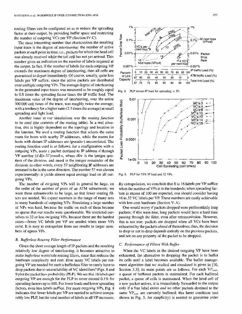
KATEVENIS et al.: WORMHOLE IP OVER (CONNECTIONLESS) ATM 657
routing filters can be configured so as to reduce the spreading factor at their output, by providing buffer space and restricting the number of outgoing VCs per VP (Section IV-C).
The most interesting number that characterizes the resulting input trace is the degree of interleaving: the number of active packets at each point in time, i.e., packets for which the head cell was already received while the tail cell has not yet arrived. This number gives an indication on the number of labels required at the output. In fact. if the number of labels for each outgoing VP exceeds the maximum degree of interleaving, then all cells are guaranteed to depart immediately. Of course, usually, quite less labels per VP suffice, since the active packets are distributed over multiple outgoing VPs. The average degree of interleaving in the generated input traces was measured to be roughly equal to 0.8 times the spre~tding factor times the IP traffic load. The maximum value of the degree of interleaving, over the entire 300 000 cell times of the trace, was roughly twice the average, with a tendency for a higher ratio (2.5 times the average) at small spreading and light load.
Another issue m our simulations was the routing function to be used (the contents of the routing table). In a real situa- tion, this is highly dependent on the topology and location in the Internet. We used a routing function that selects the same route for hosts with nearby IP addresses, while the routes for hosts with distant IP addresses are (pseudo-) uncorrelated. The routing function used is as follows: for a configuration with n outgoing VPs, route a packet destined to IP address d through VP number (d div 57')rood n, where d iv is the integer quo- tient of the division, and m o d is the integer remainder of the division; in other words, every 57 neighboring IP addresses are assumed to be in the same direction. The number 57 was chosen experimentally: it yields almost equal average load on all out- going VPs.
The number of ou~:going VPs will in general be large, on the order of the number of ports of an ATM subnetwork; we want these subnetworks to be large, so that fewer routing fil- ters are needed. We expect numbers in the range of many tens to many hundreds of outgoing VPs. Simulating a large number of VPs was hard, because the traffic on each of them became so sparse that our resu.lts were questionable. We restricted our- selves to 32 or less ow:going VPs, because these are the hardest cases fewer VC labels per VP are needed when more VPs exist. It is easy to extrapolate from our results to larger num- bers of egress VPs.
B. Bufferless Rounng Filter Performance
Given ttie short average length of IP packets and the resulting relatively tow degree of interleaving, it becomes attractive to make bufferless worrrdaole routing filters, since that reduces the hardware complexity and cost. How many VC labels per out- going VP are needed fi~r such a bufferless filter to rarely have to drop packets due to unavailability of VC identifiers? Figs. 8 and 9 plot the packet loss probability (PLP). We see that 16 labels per outgoing VP are enough for the PLP to never exceed 0.1% for spreading factors up to 100. For lower loads and lower spreading factors, even less labels suffice. For more outgoing VPs, Fig. 8 indicates that fewer labels per VP are needed to achieve compa- rably low PLP, but the total number of labels in all VP increases.
o~
Percent of Link
Capacity
1 % = - . . . . . . . . . . . . . . . . . . . . . . . . . . . . . . . . . . . . . . . . . . . . . 1%
VC,sper.~ ~/./ ~ ~ ~ ..'"" next hopi 8 . ~2 " - ~ ..'V
0.01% ......... :/'- ~-': ........ ~_;/r .... -.~-.~-'--~- 0.01% Packet ,,':,,-'" _.-1.6/" ~.~" ~ Drop
16 "'; . . . . . . . . . . . 414 VC"~ Rate 0.001% next hops (VPout) per next ho.PL 0.001%
1'0 2'0 3'0 4~0 5'0 6P0 7r0 8~0 9'0 100 IP traffic LOad (%) 6~7 6~0 5'0 4r0 3'0 210 1'0 ~ ATMtraffioLoad(%)
6'7 7'0 7'5 8'0 8~5 9'0 9r5 l~)0Zotal link Load (%)
Fig. 8. PLP versus IP load for spreading ---- 50.
¢/)
_Q v
J 3
..I3 £ (/)
0 . . J -$ 2 ~ 0
n
0.01
0.001
0.0001
~// / / / / '
/ I l
/
....... .M,C"s: 3 * ] ..,~ ........ V C ' s : 4 . .~ . -s .
.-" x , - ' s" ~ ........... V.~S:.8 .........
" ," .V(~'s:IO -~,~ ..... /~a"
~" . j .... , , ' "VC's: , t2" - ....... ,, ,., .... . , . , .f- ¢" ~- k(C s '14 .......
" z .... ,./ ,-""VC's:- ' l6 "- ....... ,:" / ' / . . - .o-'"
/ ×" ~ ........ E' ~" ...... / ¢ '
/ / . / :, ~f !
1 e - 0 5 ' . . . . . ' ' ' 0 10 2 0 3 0 4 0 5 0 6 0 70 80 90 100
Cell Spread ing (cell t imes)
Fig. 9. PLP for 75% IP load and 32 VPs.
By extrapolation, we conclude that 8 to 16 labels per VP suffice when the number of VPs is in the hundreds; when spreading fac- tors in excess of 100 are expected, one should consider having 16 to 32 VC labels per VP. These numbers are easily achievable with low-cost hardware (Section V-A).
One would worry if packets dropped were preferentially long packets; if this were true, long packets would have a hard time passing through the filter, even after retransmission. However, this is not true: packets are dropped when all VCs have been exhausted by the packets ahead of themselves; thus, the decision to drop or not to drop depends entirely on the previous packets, and not on any property of the packet to be dropped.
C. Performance of Filters With Buffer
When the VC labels in the desired outgoing VP have been exhausted, the alternative to dropping the packet is to buffer its cells until a label becomes available. The buffer manage- ment algorithm that we studied and simulated is given in [10, Section 3.3]; its main points are as follows. For each VPout, a queue of buffered packets is maintained. For each buffered packet, a queue of cells is maintained. When the head cell of a new packet arrives, it is immediately forwarded to the output only if a free label exists and no other packets destined to the same VPout are currently buffered; this latter condition (not shown in Fig. 5, for simplicity) is needed to guarantee order

658 IEEE/ACM TRANSACTIONS ON NETWORKING, VOL. 9, NO. 5, OCTOBER 2001
o
.13 X
600
500
400
300
200
100
0 0
,..."
VC's:l ,.-':"* / VC's:~ ....... / VC"s:3 ........
/ ,V'C's:4 .............. ..,'" VC's:8 ........
x.." , t . . . . . - . - - * I i i i i i i
10 20 30 40 50 60 70 80 90 100 Cell Spreading (cell times)
Fig. 10. Buffer needed under 75% IP load, 32 VPs.
0 v " O
:;3
, ,Q X
30000
25000
20000
15000
10000
5000
0
t IP:0.25 o IP:O.50 ...... / IP:0.75 ..9,Z~ 1P:0~5/-4~---... I / . / . - ' "
.if ..,"
j . . J ..Q'" I "
10 20 30 40 50 60 70 80 90 100 Spreading
Fig. 11. Reassembly buffer space: 1 VPo,~t, 1 VCout.
preservation and nonstarvation of buffered packets. Otherwise, the new packet is buffered at the tail of the queue for its VPout. When cells of buffered packets arrive, they get buffered at the tail of the queue for their packet (the connection table points to that queue). When a label for a certain VPout is freed, the front packet in its queue of buffered packets is examined; if no label has yet been assigned to that packet, then this label is given to it, and the VP is marked as ready for transmission. The output scheduler gives priority to incoming cells that can be imme- diately forwarded without buffering (this includes native-ATM traffic); in the lack of such cells, it serves VPs with buffered cells that are ready for transmission, in a round-robin fashion.
For a routing filter that buffers cells in the absence of out- going VC labels, the first question concerns the amount of buffer space needed. Fig. 10 gives the maximum buffer occupancy for various spreading factors and number of VCs per VPout; other related measurements appear in [10, Figs. 16 and 18]. We see that a few tens of kilobytes of buffer space suffice even when there are as few as four VC labels per outgoing VP.
A special case of interest is IP packet reassembly at an exit point from the ATM network (Section II-B). The routing filter will automatically perform packet reassembly when configured
E t . ~
o
.-$
0
30000
25000
20000
15000
10000
5000
0 0
IP:0.25 • IP:O.50 ........ IP:0.75 ........ / : IP:0.85 --~:---.
/.Jill. ............ -
/ ,," 1" , j / ,."'" f . . . -"
./..." Q.- / "
10 20 30 40 50 60 70 80 90 100 Spreading
Fig. 12. Average reassembly delay (1 VPout, 1 VCout).
with a single outgoing VC label. Fig. 11 plots the buffer space needed in this case for various spreading factors and IP traffic loads. We see that a large buffer space, in the megabyte(s) range, is needed now.
Concerning delay, we measured the time elapsed from the arrival of each packet' s tail cell until that same tail cell departed from the wormhole filter. The measurements in [10, Figs. 20 and 21], for 32 VPs times four labels per VP indicate average delays in the range of tens to few hundreds of cell times, and worst-case delays in the range of several hundreds to thousands of cell times: when there are insufficient VC labels, most packets suffer very little, but some packets suffer a lot, thus making QoS quite unpredictable.
Finally, Fig. 12 plots the delay incurred by packet re- assembly, at an exit point with 1 VP and 1 VC. In the case of reassembly both the average and the maximum delay are large; the worst-case delay is only about twice longer than the average. The delays encountered are in the thousands or tens of thousands of cell times (milliseconds, for gigabit links); only for very small spreading values do we see delays in the 0.1-0.5-ms range. It is important to realize that wormhole IP over ATM saves us from precisely these reassembly delays at every IP router encountered on the path of a packet!
D. Shaping per Outgoing VP
For reasons of QoS in the ATM network, one may want to perform traffic shaping for the VPs that carry IP traffic; worm- hole filters are convenient places to perform this. We simulated a leaky bucket shaper per outgoing VP, placed right at the exit of the basic routing filter. Every IP-type cell that is allowed to depart from the basic filter is then subject to shaping: if it finds no credit in the leaky bucket of its VP, it has to wait in a per-VP queue. We simulated bucket sizes (burstiness factors) of 1 or 5. The rate of credit generation (bucket fill rate) was set at:
Average IP Traffic Load Rate Lim per VP = x Rate Factor.
Number of Egress VPs
If the cells were uniformly distributed over all outgoing VPs and over the entire simulation interval, then a Rate Factor of 1 would just suffice for the cells to get through with negligible

K A T E V E N I S e t al.: W O E M H O L E IP O V E R ( C O N N E C T I O N L E S S ) A T M 659
140
120 E
100 o
80
"~ 60 o o_ 40
< 20
0
Fig. 13.
I
0 2
':~ . . . . SPREADING; 5 ~ ' 1 SPREADING: 10 ...... ~, SPREADING: 20 ........ ~A SPREADING: 40 ............ ~ : \ SPREADING: 50 .......
i iiii,.ii~ SPREADING:100 .......
£... ,, ,,
i",:,,",,",,
"%~..~7 .........
4 6 8 10 12 14 16 18 20 noshapmg Rate Factor
Leaky bucke! with burst = 5 (50% IP load, 32 VPs x 8 VCs).
delay. Of course, no such uniform distribution exists, neither in VPs nor in time, so rate factors significantly greater than 1 are needed in order to avoid excessive delays due to shaping.
Fig. 13 shows the average packet delay for various rate factors and spreading values, and for no shaping (rightmost points). A rate factor of 10 corresponds to a rate of (50%/32) x 10 ~ 16% for each (per-VP) leaky bucket. For such a shaping rate, we see that the average packet delay does not exceed 25 cell times (40 cell times for allowed burstiness of 1). For spreading values of z;0 or more the average packet delay is negligible--larger spreadings roughly correspond to stricter shaping upstream in the network. For this same rate factor of 10, the maximum packet delay seen during the simulation (not shown here) ranged from 500 (large spreadings) to 1000 (small spreadings). The total buffer space needed (not shown in the figures), for the basic routing filter as well as for the shaping queues, is less than 2(3,0 cells for a rate factor of 10, and grows to 400 cells for a rate factor of 5, and further to 1000 cells when the rate factor drops to 3.
V. HARDWARE IMPLEMENTATION
This section first describes our wormhole IP over ATM pro- totype and shows its low cost. Next, we analyze the cost and complexity of implementing such routing filters, with or without buffer memory, at higher speeds.
A. Hardware Prototype
We built an FPGA-based prototype of a bufferless bidirec- tional wormhole IP over ATM routing filter with two OC-3 ports (155 Mb/s in each direction). The prototype board is described in detail in [11], [16]; its photograph appears in Fig. 14, and its block diagram is given in Fig. 15. The two 32-MB DRAM modules (SIMM) plug into the sockets on the right of the prototype board; the two optical fiber sockets and the two SONET/UTOPIA interfaces are on the left; the parallel port that connects to a PC running the management software is at the top. The six-layer PCB is 7 in long by 5 in wide.
The FPGA, in the center of the board, implements all of the wormhole IP functionality, plus interface to the management
Fig. 14. Photograph of the 2 × 155 Mb/s prototype.
I A TM Conn. Table 2 x 4K VPs x 32 VCs x
DRAM SIMM ]~ 2(st)+12(VPNCout)+... ] | IP Routin Table
TA To To L 16M+2#,eve, xt6b Altera EPF [ [ I
16K100 #11 #32 "[14 BQC208-1 TNET 155 Mb/s Q C 2 0 8 ~ _ 1500PCM 155 Mb/s
1/ ~'t SONET I - - E L - - ~ F P G , A, ~ SONET i 1, ~> OC-3c [ to I ~.v I 4u Iv]t~z 120 MHz I to / OC-3c
UTOPIA ~ 119+27+62 pine ~ UTOPIA I < ":1 155 Mb/s hv#~zx " -~ : ' ~ 155 Mb/s
clock, reset-~'3 [ ~ 17 "',, debugging ~ ~ ", VC free list (bit-map)
128 next-hop VPs x 32 VCs
Management PC Software }parallel port (ECP mode)
Fig. 15. Block diagram of the bufferless prototype.
software and hardware assistance for mass routing table up- dates. All these occupy just 2100 logic cells (roughly 10 thou- sand gates), 1100 flip-flops, and 10 kb of on-chip SRAM (8 kb for the free list and 1.6 kb for the cell buffer), for both directions of the filter. This demonstrates the basic thesis of the paper, that the wormhole IP routing filter is a low-cost hardware device. In terms of design complexity, the FPGA was described in about 2200 lines of synthesizable Verilog code.
We briefly describe the data structures maintained by the filter and their allocation to physical memories; for more details see [11], [16]. The Routing Table (RT) is organized as in [8], in two levels. Each entry is 16 bits long, in both levels: one validity bit and 12 bits of index to the second level; or one validity bit, five bits for prefix length (for RT updates only), and seven bits for VPout. The first level contains 224 entries (32 MB), and is held in one DRAM SIMM; the second level contains 212 blocks of 2 s entries each (2 MB), and occupies the first half of the other SIMM. The free list of the second level is kept within the free blocks themselves.
The two Connection Tables (CT), one per direction, reside in the other half of the latter SIMM, and contain one entry for each VP/VC that can be used by the filter. Each CT entry (32 bits) contains: an 11-bit tag to match the most significant bits (MSBs) of VCin ; a 5-bit translation for the least significant bits (LSBs) of VCin; a 7-bit VP translation; and two bits for the state

660 IEEE/ACM TRANSACTIONS ON NETWORKING, VOL. 9, NO. 5, OCTOBER 2001
of the connection. In our prototype implementation, each CT contains 217 = 128K entries of 32 bits each (0.5 MB), and is configured as 4K VPs x 32 VCs per VP. The CT is indexed using the full VP (12 bits) and the five LSBs of VCin. The 11 MSBs of the VC of the incoming cell are then compared against the corresponding tag in the CT entry; if the two fields match, the entry is valid, otherwise the cell is of native-ATM type. In this way, we can effectively choose, for each VP, the set of the 32 consecutive VCs that are dedicated to IP-type traffic.
The Free List of available VC labels per VP was implemented as a bit-map, kept in internal SRAM of the FPGA. The size of such on-chip SRAM limited the number of IP-type egress VPs to 128, with 32 VC labels in each. Off-chip DRAM is our most heavily used resource; it is shared according to a static time schedule, [11, Fig. 5]. The two RT lookup reads and the one CT read-modify-write, per direction, occupy 70% of the DRAM throughput, leaving the rest for refreshes and RT up- dates. The routing delay is fixed, equal to about 2.3 /~s plus SONET/UTOPIA conversion time, for all IP packets.
We tested the hardware of our prototype extensively, and ver- ified its correct operation. The test environment consisted of two personal computers with Nicstar ATM network interface cards and two ATM switches. The source PC was transmitting data--native ATM and AAL5 packets--as fast as possible. 3 The destination PC was reading the data and verifying their cor- rect arrival. We run our experiments for several hours and var- ious AAL5 buffer sizes, transmitting several million buffers and making tens of millions of accesses to the board's structures. Al- though the ATM interface on the receiving PC included packet reassembly capability in its hardware and could thus receive multiple packets on multiple VCs with their cells interleaved in time, the protocol stack software refused to receive packets of a given IP flow from multiple VCs. In the lack of modified protocol software or a filter with buffer able to perform packet reassembly, out tests went up to four flows on four different VP/VCs. All our tests indicated that the prototype hardware op- erated correctly.
B. Other Configurations
Low-cost FPGA-based implementations are also possible at OC-12 (622 Mb/s), and perhaps at OC-48 (2.5 Gb/s). An example of a possible OC-12 FPGA-based implementation is given in [10, Sect. 4.1 and 4.2]; a memory access timing analysis in included. Section V-C addresses higher speeds.
Another issue is the implementation of routing filters with buffer. The additional data structures needed are the packet queues (one per egress VP), the cell queues (one per buffered packet), the cell buffer memory, and the list of ready VPs (for output scheduling). During a cell time, we may need to transfer up to two cells between the FPGA and the cell buffer, and perform an operation on two packet queues and two cell queues, when the incoming cell is the first of a packet to an outgoing VP with no free VCs, and, in parallel, we are transmitting the tail cell of another packet from the buffer. Overall, a routing filter with buffer is appreciably more complex than a bufferless
3To overcome software limitations, we initiated all data transfers using raw ATM sockets, but we set the filter to expect IP traffic when so desired. The PCs were running the Linux 2 . 2 . 3 0 S with atm-on-linux patch 0.61.
one, especially in terms of design complexity. Hence, we see no serious reason for going to a filter with buffer, unless one wants to support packet reassembly at ATM "exit points."
C. Pipelined Operation at 10 Gb/s and Beyond
The wormhole routing filter operation is simple enough to be implementable at much higher speeds, using more paral- lelism. Given the relatively small sizes of the connection table and VC free list, according to the numbers seen in Section IV, these memories can be implemented on-chip, at high speed, and pose no serious problem. The IP Routing Table (RT) is large, and probably needs off-chip DRAM. For 10 Gb/s = 24 Mcell/s operation, with two DRAM accesses per cell needed for RT lookup, a DRAM throughput of 48 Maccesses/s is required. Modem synchronous DRAMs (SDRAM) offer rates up to one access every two clock cycles at 133 or more MHz, i.e., 67 or more Maccesses/s--hence sufficient for our pur- poses-provided memory interleaving is used and accesses are distributed to four or more (on-chip) banks. This latter requirement can be satisfied as follows: place the first and second levels of the RT in separate banks, make two copies of each level and place these in separate banks, and alternate accesses to the four resulting banks. The operation of the routing filter needs to be pipelined, but this can be done in a straightforward way, e.g., as shown in [10, Fig. 30]. As with most pipelines, there are dependencies among the pipe stages, but these can be resolved using bypassing--a technique com- monly used in all processor designs.
V I . C O N C L U S I O N
Wormhole IP over ATM applies techniques from multipro- cessor interconnection networks to routing IP packets at high speed and low cost over existing and future ATM switching infrastructure. High-speed switching hardware works with fixed-size cells. To be switched at high speed, variable-size IP packets are segmented into cells. Once such a segmented packet enters an ATM network, it can be routed, according to its IP destination address, from subnetwork to subnetwork, fully in hardware, without intermediate reassembly, with negligible delays, at low cost. Key observations are that: 1) IP routing table lookups can be performed in hardware, within a few clock cycles; 2) the IP destination address is contained in the first cell after segmentation, hence we can cut-through at the cell level; 3) VC label to packet binding can be performed upstream, locally, in hardware, within a couple of clock cycles, and, thus, 4) this binding may just refer to individual packets, without need for flow recognition. ATM switches are fully adequate to provide high-speed switching, dynamically shared among IP and native ATM traffic--we only need to add wormhole IP routing filters; these filters are low cost devices and only need to be placed sparsely, in between existing ATM subnetworks. The bufferless organization is simpler, and our simulations indicate that it performs very well with just a few tens of labels per egress next-hop path; thus, a data buffer is basically only needed for packet reassembly. We built and successfully tested a buffefless routing filter at 2 × 155 Mb/s, using a few thousand gates and a few kilobits in an FPGA, and a modest amount of

KATEVENIS et al.: WORMHOLE IP OVER (CONNECTIONLESS) ATM 661
of f -chip D R A M ; the ha rdware for ope ra t ion at 10 Gb/s and
b e y o n d is feas ib le today.
ACKNOWLEDGMENT
The authors w i sh to t h a n k E B o n o m i and M. K. W o n g for
he lp ing t hem with the l i terature. They also t h a n k the C S - 5 3 4
class of Spr ing 1998 at the Unive r s i ty of Crete, wi th in w h i c h
this work began as a class project , and, in part icular , A. Hatz i s -
tamat iou, D. Serpm~os, and G. S tamoul i s . G. Ka loker inos , S.
Lyberis , and M. Ligerak is he lped the authors in the des ign and
d e b u g g i n g of the proto type . T. Papa thanas iou , A. Danal i s , and
E Ki tsos he lped t h e m in se t t ing up and c o n d u c t i n g the proto-
type test ing. V. Sifts, E. Marka tos , and S. Sar tze tak is p rov ided
va luab le f eedback and gu idance t h r o u g h o u t the project . T h e au-
thors very m u c h t h a n k t h e m all, and they also t h a n k N L A N R
for m a k i n g the IP traffic t races avai lable .
REFERENCES
[1] R. Barnett, "Connectionless ATM," IEEElectron. Commun. Eng. J., pp. 221-230, Oct. 1997.
[2] S. Borkar et ai., "Supporting systolic and memory communication in iWarp," in Proc. 17th Int. Symp. Computer Architecture (ACM S1GARCH), vol. 18, June 1990, pp. 70-81.
[3] A. Brodnik, S. Carlsson, M. Degermark, and S. Pink, "Small forwarding tables for fast routing lookups," in Proc. ACM SIGCOMM, Cannes, France, Sept. 1997, pp. 3-14.
[4] W. Dally and C. Seitz, "Deadlock-free message routing in multipro- cessor interconnecti3n networks," IEEE Trans. Comput., vol. C-36, pp. 547-553, May 1987.
[5] W. Dally, "Virtual-channel flow control," lEEE Trans. Parallel and Dis- tributed Syst., voI. 3, pp. 194-205, Mar. 1992.
[6] B. Davie and ~: Rekhter, MPLS: Technology and Applications. San Mateo, CA: Morgan Kanfmann, 2000.
[7] M. Galles, "Spider: A high-speed network interconnect," IEEE Micro, vol. 17, no. 1, pp. 34-39, Jan./Feb. 1997.
[8] E Gupta, S. Lin, and N. McKeown, "Routing lookups in hardware at memory access speeds," in Proc. IEEE Infocom, San Francisco, CA, Apr. 1998, [Online]. Available: http://tiny-tera.stanford.edu/~nickm/pa- pers/Infocom98_lookup.ps or Infocom98_lookup.pdf.
[9] E Gupta and N. McKeown, "Classifying packets with hierarchical intel- ligent cuttings," IEEE Micro, vol. 20, no. 1, pp. 34-41, Jan.-Feb. 2000.
[10] M. Katevenis, la. VIavroidis, Io. Mavroidis, and G. Glykopoulos. (1998, July) Wor~nhole IP over (connectionless) ATM. ICS, FORTH, Heraklion, Crete, Greece. [Online]. Available: http://archvlsi.ic s. foVth.gr/wormholelP/arch98/wlP_98.html or wlP_98.ps
[11] Ia. Mavroidis. ~1999, June) Hardware implementation of a routing filter to support wormhole IP over ATM. ICS, FORTH, Tech. Rep. FORTH-ICS/TR-258, Heraklion, Crete, Greece. [Online]. Available: http://archvlsi.ic s.forth.gr/wormholelP/wlP_mavro99.ps
[12] A. Moestedt and P. Sjodin, "IP address lookup in hardware for high-speed routing," in Proc. IEEE Hot In terconnects 6 Symp., Stanford, CA, Aug. 1998, [O~fline]. Available: http://www.sics.se/~am/HotI.ps, pp. 31-39.
[13] P. Newman, G. Mins,hall, and T. Lyon, "IP switching: ATM under IP," 1EEE/ACM Trans. Networking, vol. 6, pp. 117-129, Apr. 1998.
[14] U.S.A. National Laboratory for Applied Network Research (NLANR). (1997, Jan.) IP traffic trace from FIXWEST West Coast federal interexchange node. [Online]. Available: http://www.nlanr.net; ftp://oceana.nlartr.nen/Traces/FR+/9701/
[15] G. Parulkar, D. Schmidt, and J. Turner, "altPm: A strategy for integrating IP with ATM," in Prac. ACM SIGCOMM, Cambridge, MA, Aug.-Sept. 1995, pp. 49-59.
[16] G. Sapountzis. (1999, June) IP routing table organization and man- agement in the wormhole IP routing filter. ICS, FORTH, Tech. Rep. FORTH-ICS/TR-257, Heraklion, Crete, Greece. [Online]. Available: http://archvlsi.ics, forth.gr/wormholelP/wlP sapou99.ps
[17] M. Waldvogel, G. Varghese, J. Turner, and B. Plattner, "Scalable high- speed IP routing lookups," in Proc. ACM SIGCOMM, Cannes, France, Sept. 1997, pp. 25-36.
Manolis G. H. Katevenis (M'84) received the Diploma degree in electrical engineering from the National Technical University of Athens, Greece, in 1978, and the M.Sc. and Ph.D. degrees in computer science from the University of California, Berkeley, in 1980 and 1983, respectively.
He is a Professor of Computer Science at the University of Crete, and Head of the Computer Architecture and VLSI Systems Laboratory, Institute of Computer Science, Foundation for Research and Technology-Hellas (FORTH), in Heraklion, Crete,
Greece. His interests are in packet switch architecture, high-speed network architecture, computer architecture, and VLSI systems.
Dr. Katevenis received the 1984 ACM Doctoral Dissertation Award for his thesis on reduced instruction set computer architectures for VLSI. He is a member of the ACM.
Iakovos Mavroidis received the B.Sc. degree in computer science from the University of Crete, Greece, in 1999, and the M.Sc. degree in computer science from the University of California, Berkeley, in 2001.
He is currently a Design Engineer with M1PS Technologies, Mountain View, CA, working on the R20K processor. His interests include micropro- cessor architecture and design, computer networks, and digital VLSI systems.
Georgios Sapountzis received the B.Sc. degree in computer science from the University of Crete, Greece, in 1999. He is currently a graduate student of computer science at the same university. He is mainly interested in high-speed computer network systems.
Mr. Sapountzis is a student member of the ACM.
Eva Kalyvianaki received the B.Sc. degree in com- puter science from the University of Crete, Greece, in 2000. She is currently a graduate student of computer science at the same university. Her research interests include operating systems and computer architecture.
Ioannis Mavroidis received the B.Sc. degree in com- puter science from the University of Crete, Greece, in 1998, and the M.Sc. degree in computer science from the University of California, Berkeley, in 2000.
He is currently a Senior Engineer at Applied Micro Circuits Corporation, Andover, MA, working on chips for optical networks. His interests include computer networks, microprocessor architecture and digital VLSI systems.
Georgios Glykopoulos received the B.Sc. and M.Sc. degrees in computer science from the University of Crete, Greece, in 1996 and 1998, respectively.
He is currently an IC Design Engineer at Glo- betechsolutions, Thessaloniki, Greece. His interests include design, verification, and diagnostics of high-speed ASICs, and PCB and FPGA design.