wp4 report version 1.00-without...
TRANSCRIPT
FINAL REPORT
Project Acronym:
ICT4SMARTDG
Grant Agreement number: 238878
Project Title:
Thematic Network on ICT Solutions to enable
Smart Distributed Generation
Project Coordinator: Peter Moray
European Utilities Telecom Council
287 Avenue Louise, 1050 Brussels (Belgium)
Telephone: +32 2 645 2677
Email: [email protected]
Project Website: http://www.ict4smartdg.eutc.org/
Project Logo:
2 of 70
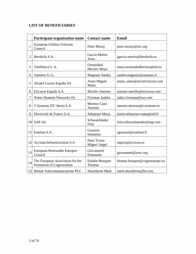
LIST OF BENEFICIARIES
Participant organisation name Contact name Email
1 European Utilities Telecom
Council Peter Moray [email protected]
2 Iberdrola S.A. García Martin
Jesus [email protected]
3 Telefónica S. A. Ormazábal
Herrero Maya [email protected]
4 Samares S.r.L. Magnani Sandra [email protected]
5 Alcatel Lucent España SA Amor Miguel
Matía
6 Ericsson España S.A. Morillo Antonio [email protected]
7 Nokia Siemens Networks Oy Forsman Jaakko [email protected]
8 T-Systems ITC Iberia S.A Moreno Cano
Antonio [email protected]
9 Electricité de France S.A. Sebastian Maria [email protected]
10 SAP AG Schwarzländer
Fritz [email protected]
11 Eutelsat S.A. Grazzini
Sebastien [email protected]
12 Acciona Infraestructuras S.A Paris Torres
Miguel Angel [email protected]
13 European Renewable Energies
Council
Giovannetti
Emanuela [email protected]
14 The European Association for the
Promotion of Cogeneration
Esdaile-Bouquet
Thomas
15 British Telecommunications PLC Shackleton Mark [email protected]

3 of 70
Table of Contents
1. Introduction ............................................................................................................... 7
2. Key Messages ............................................................................................................. 9
3. Summary of WP1, WP2, and WP3 ........................................................................ 12
3.1. Work Package 1 ............................................................................................................... 12
3.2. Work Package 2 ............................................................................................................... 13
3.3. Work Package 3 ............................................................................................................... 14
4. WP4 Objectives ........................................................................................................ 16
4.1. Types of Distributed Generation .................................................................................... 16
4.2. ICT Solutions for the Selected Scenarios ...................................................................... 16
5. Integrated Communication Network for the Smart Grid ................................... 19
5.1. Smart Grid and Other Applications .............................................................................. 19 5.1.1. Traditional and Current Utility Applications ...............................................................................19 5.1.2. New and Evolving Utility Applications including Smart Grid Applications ................................20
5.2. Integrated Communication Network Requirements .................................................... 21 5.2.1. Application Traffic Characterization ...........................................................................................21 5.2.2. Network Performance, Reliability, and Security ..........................................................................22 5.2.3. Support for Legacy Systems, Networks, and Protocols ................................................................23
5.3. Integrated Communications Network Architecture..................................................... 24 5.3.1. Traffic Aggregation at Network Endpoints ..................................................................................25 5.3.2. Core Network (WAN) ...................................................................................................................25 5.3.3. Access Networks (FANs) ..............................................................................................................26 5.3.4. Highlights of the Edge-Core Architecture ...................................................................................29
5.4. Network Ownership ........................................................................................................ 30
5.5. Communication Network Transformation ................................................................... 31 5.5.1. Planning Network Transformation ..............................................................................................31 5.5.2. Early Years of Network Transformation ......................................................................................32 5.5.3. Throughout Network Transformation years .................................................................................32
6. Wireless Access Networks (Wireless FANs) .......................................................... 34
6.1. Candidate Wireless Network Access Technologies ...................................................... 34 6.1.1. Smart Grid Endpoints connecting to Wireless Access Networks .................................................35 6.1.2. Neighborhood Area Networks (NAN) ..........................................................................................36 6.1.3. Wireless Access Networks or FANs .............................................................................................36
6.2. A Blueprint for Wireless Access Network Evolution ................................................... 38
6.3. A Case for LTE ................................................................................................................ 39 6.3.1. Driving forces ..............................................................................................................................39 6.3.2. Scalability of LTE ........................................................................................................................39 6.3.3. Bandwidth Requirements in an LTE Macro Cell .........................................................................40
7. Distributed Generation-specific ICT Considerations .......................................... 42
7.1. ICT Requirements ........................................................................................................... 42
7.2. ICT for Retail Energy Market ....................................................................................... 42 7.2.1. Traditional market models with bulk power generators ..............................................................43 7.2.2. Two-stage market model with aggregators ..................................................................................44

4 of 70
7.3. ICT for Automated Demand Response ......................................................................... 45
7.4. ICT in Support of Grid Stability .................................................................................... 47
8. Data Management with Large Scale Distributed Generation ............................. 49
8.1. Need for Secure and Reliable information access ......................................................... 49
8.2. Requirements for a Secure Smart Grid Information Infrastructure ......................... 50
9. Summary and Recommendations .......................................................................... 52
10. Completed and planned dissemination activities .............................................. 55
References ........................................................................................................................ 58
Appendix A: Integrated Communication Network for the Smart Grid .................... 60
Appendix B: Wireless Access ......................................................................................... 65
5 of 70
Executive Summary
This document is the final report on the European Commission sponsored project
ICT4SMARTDG - Thematic Network on ICT Solutions to enable Smart Distributed
Generation. The main objective of WP4, the final technical WP is the definition of steps
forward for the promotion of large scale implementation,
One of the first tasks of WP4 was to derive the key messages of the ICT4SMARTDG
project. There is a wide consensus on the following six key messages:
Key Message 1: ICT for distributed generation must be an integral part of ICT for the
overall smart grid and
• Support distributed generation as well as other smart grid applications
• Support legacy applications and protocols
Key Message 2: With distributed generation sources expected to be spread widely over
the utility territory – often inaccessible to wire-line networks, utility access to wireless
networks is necessary
• Develop a wireless access blueprint
• Adoption of new technologies including LTE and WiMAX.
Key Message 3: While current utility OpTel* service delivery methods favor self-
provided communication networks, incorporating carrier (service provider) networks may
be considered for some of the applications over a period of time
• Mix of self-provided and carrier networks
• Utility requirements on network access, performance, reliability, and security.
Key Message 4: In addition to supporting integration of distributed generation in the
utility grid, ICT will need to support many other applications that will be expanded or
developed for energy and grid management. These applications include:
• The “virtual power plant”
• Retail Energy Markets (including the role of an aggregator)
• Demand Response
Key Message 5: Communication network performance (including QoS), reliability, and
security must be managed so as not to adversely affect electric grid operations when
integrating distributed generation into the utility grid
• Eg, minimize communication network delays’ impact on power grid transients
Key Message 6: Utilities and suppliers of ICT (communication service providers and
software companies) need a detailed dialog about the viability and actual availability of
new ICT technologies for use by the smart grid
• IP as the networking protocol
• Need for new data management architecture
• Standardization: Persuade standards bodies like ETSI and CENELEC to include
smart grid ICT requirements in their standardization efforts.
As stated in the goals for WP4, we provide recommendations for promotion and
implementation of the ICT for large scale deployment of distributed generation. Four

6 of 70
scenarios are identified for near term solution development. This report provides details
of these solutions
Scenario 1: Communication network for distributed generation must be a part of an
integrated communication network that supports all applications of the utility Op-Tel
including the current and future smart grid applications.
Highlights of Solution 1
• Set context for ICT for distributed generation
• A high performance, highly reliable, and highly secure integrated IP network
architecture that supports all smart grid and other utility applications
• IP as the networking protocol. But support of legacy protocols (such as TDM) and
networks must be maintained for a period of time.
• A mix of utility self-provided and carrier Field Area Networks based on the
utility’s preference, costs, and SLAs supported by the carriers.
Scenario 2: Evaluation of wireless networking technologies. Communication network
access to all distribution generation locations in a utility territory will be very difficult, if
not impossible, without wireless networking access.
Highlights of Solution 2
• Candidate wireless technologies based on availability of spectrum, coverage,
performance, reliability, security and costs.
• Develop an evolutionary roadmap (blueprint) for wireless networks consistent
with spectrum availability and new evolving wireless technologies
• Work with regulatory agencies, industry forums, standards, and other
organizations that need critical infrastructures (eg Public Safety, Transportation)
Scenario 3: ICT for large scale distribution presents unique requirements that must be
satisfied in the integrated communication network. This includes incorporation of DG in
smart grid applications on one hand and robust utility operations in presence of
communications connectivity to DG on the other.
Highlights of Solution 3
• These three applications must be supported:
• Retail energy market
• Automated and highly granular demand response
• Electric grid stability in the presence of transients introduced by variability of
the energy supply from distributed energy sources
Scenario 4: With explosive growth of endpoints (such as meters, distributed SCADA,
and distributed generation), and requirements for access to the corresponding data from
multiple applications, a secure and low latency data management architecture is required.
Highlights of Solution 4
• A secure and low latency data management architecture is required for managing
data generated at a very large number of endpoints and applications thereof
• For security and delay considerations, a network based push-pull architecture
(rather than server-client) is preferred
• Data privacy considerations are of utmost importance.
7 of 70
1. Introduction
This document is the final report on the European Commission sponsored project
“ICT4SMARTDG - Thematic Network on ICT Solutions to enable Smart Distributed
Generation”. The project was divided into the following six work packages. (the work
package leader companies are identified in parentheses):
WP1 (Iberdrola):Exchange of information and experiences
WP2 (Telefonica): Achieve consensus on benefits of available solutions
WP3 (Samares): Identification of non-technical barriers for large scale deployment
WP4 (Alcatel-Lucent): Definition of steps forward for promotion of large-scale
implementation
WP5 (EUTC): Dissemination and feedback
WP6 (EUTC): Project management and coordination
WP1, WP2, and WP3 have been successfully completed and are summarised in
subsequent sections of this report. These three work packages are pre-requisite for the
work of WP4 tasks and this report. As stated in the goals for WP4, we provide the
recommendations for promotion and implementation of the ICT for large scale
deployment of distributed generation.
The output of WP4 has been divided in four broad scenarios with solution
implementation recommendations provided for each of these scenarios. These scenarios
are:
1. Scenario 1: Communication network for distributed generation must be a part of
an integrated communication network that supports all applications of the utility
Op-Tel including the current and future smart grid applications.
2. Scenario 2: Evaluation of wireless networking technologies. Communication
network access to all distribution generation locations in a utility territory will be
very difficult, if not impossible, without wireless networking access.
3. Scenario 3: ICT for large scale distribution presents its unique requirements that
must be satisfied in the integrated communication network. In particular, ICT must
support grid stability in the presence of interconnected DG and also support
applications like retail energy markets and demand response that is more granular
incorporating large scale DG rather than just the conventional energy resources.
4. Scenario 4: With explosive growth of endpoints (such as meters, distributed
SCADA, and distributed generation), and requirements for access to the data
generated from these endpoints from multiple applications, a secure and low
latency data management architecture is required.
As the concluding work package of the technical part of ICT4SMARTDG, it is important
that these recommendations are based on a few salient key messages that not only capture
the consensus of the thematic network of ICT4SMARTDG but also provide context for

8 of 70
the few chosen scenarios for which details of solution alternatives and implementation
are developed in WP4 as described later in this document.
We begin with the presentation of the key messages in Section 2. A brief summary of
work packages WP1, WP2, and WP3 is presented in Section 3. WP4 objectives are
presented in section 4, including a brief introduction to the solutions each of the four
scenarios. In sections 5-8, details on solution alternatives, implementations and
recommendations for Solutions 1-4, respectively, are presented. Concluding remarks are
presented in Section 9 with a brief summary of the important recommendations
9 of 70
2. Key Messages
These are the six Key Messages (KM):
KM1: ICT for distributed generation must be an integral part of ICT for the overall
smart grid
In particular, the communication network for the smart grid must support
communication requirements for distributed generation as well as other smart grid
applications
It is also extremely important that the smart grid ICT spans across all domains
including the utility1 critical infrastructure and delay sensitive applications.
Legacy applications and protocols (such as TDM) must be supported for a period of
time.
KM2: With distributed generation sources expected to be spread widely over the
utility territory – often inaccessible to wire-line networks, utility access to wireless
networks is necessary
Means of exclusivity of access to spectrum and other wireless infrastructure elements
such as towers should be explored. This includes opportunities for sharing spectrum
with other mission critical services such as public services, transportation, and health.
Wireless service provider (carrier) broadband networks can certainly be used, if they
guarantee the required service level agreements (SLA). However, note that these
services may not reach all the endpoints, particularly in the remote areas.
A long-term plan must be developed based on utility’s own wireless assets, expected
access to spectrum and other shared assets, tactical use of unlicensed spectrum, and
newer technologies including LTE and WiMAX.
KM3: While current utility OpTel* service delivery methods favor self-provided
communication networks, incorporating service provider (carrier) networks may be
considered for some of the applications over a period of time
The actual mix of self provided networks and carrier networks will depend on the
individual utility based on their preference, overall costs, network requirements of
mission critical applications, expediency of introduction of new applications (such as
AMI and distributed generation), availability of spectrum and other considerations.
A range of telecommunications technologies provided by the service provider
communication networks are used in many smart grid trials.
Service providers to support the utility requirements by establishing and supporting
utility-specific SLAs for network performance, reliability, and security, including
network access guarantees for mission-critical applications.
1 Throughout this document, the word “utility” refers to a generic electric power distribution company
or organization. Where necessary, specific functions within a utility will be called out.
10 of 70
KM4: In addition to supporting integration of distributed generation in the utility
grid, ICT will need to support many other applications that are new applications,
extensions of existing applications to DG, and/or applications for energy and grid
management. These applications include
Retail Energy Markets: Energy market is expected to evolve to participation by retail
and casual suppliers of distributed generation. Timely and optimal energy transaction
will require sophisticated ICT including transaction algorithms and responsive
communication network
This requires an “aggregator” function aggregating not only the stand alone
distributed generation, but also local generation at many consumer locations
including residential, business, and industrial customers.
Demand Response: Manage energy contribution from distributed generation,
including generation capabilities at residences and microgrids, for peak power
reduction as well as consumer energy management
Microgrids are special examples of distributed generation (with additional
requirement of self-supporting the essential microgrid consumption with local
generation in case of grid outage). Specific network communication protocols and
processes need to be implemented for supporting integration of microgrids into
the overall utility grid.
In fact, with large scale distributed generation, customers receive energy from a
“virtual power plant” with the utility facilitating the overall energy management
KM5: Communication network performance (including QoS), reliability, and
security must be managed so as not to adversely affect electric grid operations when
integrating distributed generation into the utility grid
An example, particularly relevant to DG: connecting renewables into the grid cause
transients due the variable natures of renewables power generation and transformation
to AC. They need to be managed by the utility with minimum possible delays based
on the communication between the DG management and utility Energy Management
Systems. Thus it is necessary that the delay contribution of the communication
networks is kept as small as possible. Thus the network QoS should make sure that
this DG-related traffic gets the appropriate QoS treatment.
KM6: Utilities and suppliers of ICT (communication service providers and software
companies) need a detailed dialog about the viability and actual availability of new
ICT technologies for use by the smart grid
Many ICT companies believe that NGN and SOA solutions are capable of meeting all
future smart grid requirements. Further, IEC 62357 Technical Report on Reference
architecture for object models, services and protocols as well as the Common
Information Management (CIM) standards IEC 61970 and 61850 [4] included in the
Technical Report provide a framework for these solutions. However, many utilities
need to be convinced about these claims and the promises of their features, realistic
delivery dates, and costs.

11 of 70
While there is a general consensus that IP will be the overall networking protocol, the
legacy applications and networks will need to be maintained over a period of time.
The ICT sector should be encouraged to prove the capability of IP services to support
the low latency mission critical applications.
With explosive growth of endpoints (such as smart meters, distributed SCADA, and
distributed generation) and need for accessing the data from multiple grid
applications distributed throughout the grid, a new data management architecture will
be required that supports very low delay data transfer as well as data privacy and
security.
Standardization is a major issue, it is important from a European perspective, that
progress is made on this issue.
Joint CEN, CENELEC and ETSI standardization activities for Smart Metering
and Smart Grid have been initiated based on mandates from the European
Commission (M441, M490). The definition of ICT requirements and functions
is/will be a major part of these activities.
12 of 70
3. Summary of WP1, WP2, and WP3
ICT4SMARTDG is a Thematic Network (TN) led by the European Utilities Telecom
Council (EUTC) dedicated to fostering and promoting large-scale integration of domestic
and distributed micro generation and promoting improvements in energy efficiency
through the implementation of innovative ICT solutions into local smart power grids.
WP1, WP2, and WP3 are summarized here.
3.1. Work Package 1
WP1 was led by Iberdrola with the intention of setting out the energy sector view of the
ICT issues associated with future approaches to large scale deployment of DG including
business models and qualification of benefits of ICT-based solutions for all stakeholders.
The approach for WP1 was designed to collect information by issuing a questionnaire
and collating the responses on order to create solid background knowledge, attain
common understanding of today’s situation in the field of distributed micro generation
including the main fields of action and ICT requirements. The information generated was
used for the development of WP2 and WP3
All the partners agreed on a template fiche to compile the different relevant experiences
undergone by each partner. Then, the thematic network decided to examine three
different scenarios. Each scenario was focused in a prominent area of smart distributed
generation; the partners were clustered in these scenarios depending on their expertise
and the nature of the experiences they provided to the thematic network common
knowledge assets.
• Scenario 1: Buildings/ Enterprises (non residential buildings)
• Scenario 2: Microgrids of domestic customers (buildings)
• Scenario 3: Isolated Houses (residential houses not connected to a Microgrid but
connected to the grid)
With the progressive implementation of the project in its first 10 months, the thematic
network readily realized that the issues to be dealt with are very complex despite the
scope of the project being well defined. Indeed, interaction among 7 different kinds of
stakeholders with different views and approaches to the same objectives gives an idea of
the difficulties of the given task.
Several key issues came out of WP1, namely:
There was a total lack of understanding of the energy network architecture within
the ICT community. An explanation of the complex layers of assets and networks
required to support the delivery of energy to domestic customers opened the way
for a greater understanding.
The level of intelligence within the asset layers is very different today but the
energy sector believes intelligence will be required in the lower levels of the
energy networks. These assets are widely dispersed across urban and rural areas
When implementing large scale DG, safety of operation and interconnection of
DG into the energy networks becomes a major complex issue

13 of 70
The energy sector view is that ICT services to support large scale DG and it’s safe
operation when connected to energy networks will be seen as “mission critical”
services and will require very high levels of reliability and resilience
The energy sector does not yet fully understand how many of the assets will need
to be “intelligent” and has not yet determined a full set of ICT requirements in
terms of bandwidth, latency and reliability
WP1 identified these issues and in conjunction with a parallel Thematic Network carried
out by SEESGEN developed a set of ICT requirements applicable to the implementation
of distributed generation. These are available on the ICT4SMARTDG web site.
3.2. Work Package 2
The work in this package has been the most challenging so far in the program of
ICT4SMARTDG activities. In the examination of suitable ICT solutions, the thematic
network had to address a number of factors that influence decisions taken by utility
companies as to how they source telecoms services today and how they may chose or be
forced to source them in the smart grid environment. The debate on self provision of
services and the outsourcing of telecoms services has become a major topic of interest
and it needs to be recognised that there is no “right way” for any specific utility company.
Today most utilities self provide operational telecoms because the public network
operators are considered not able to meet requirements on network reliability, resilience,
coverage, latency for some applications, and security. The public network operators are
addressing these issues but the utilities believe they also need total control of this critical
area of their business.
Notwithstanding this is an issue, the ICT partners in the thematic network believe carrier
networks are capable of being developed to provide ICT for applications like distributed
generation services and will bring substantial benefits in terms of an improved business
case for smart grid, skills in managing large volumes of data, and in maintaining secure
networks which they do today for many other industries.
ICT solutions have been identified by the members of the thematic network and by
vendor/service companies outside of our network. They have been grouped into:
• Communication Access Solutions
• SW and Middle Ware Solutions
• Different Layers Solutions
• Microgrid Solutions
It is also clear that all ICT or telecom related vendors and service companies have a view
on how they can support smart energy networks and applications such as distributed
generation. They are cautious as to what they are prepared to put into the public domain
in relation to their activities and service offerings. This leads to concern on what is really
achievable today from the vendor community and what is pure vapour ware. Lack of
detailed information was a limiting factor in this work package.
14 of 70
The outcome of the work has also indicated a preference from the telecom companies for
solutions based on Next Generation Networks and from the Software providers for
System Orientated Architecture solutions as the primary platform for smart grids.
What is clear from this work is that there is no suitable solution readily available today.
Rather, utilities will move forward in an evolutionary process through implementing
automation schemes in the MV/LV networks to enable control and management of
distributed generation as it moves from a scattering of DG devices through to significant
grouping in limited geographical areas towards large scale implementation. The solutions
will need to be scalable to allow for the expansion of smart networks to ever greater
geographical areas leading ultimately to the vision we have for the smart grid. Initially, as
existing carrier networks are considered to be unable to deliver the requirements of
mission critical services, utilities will seek to build their own infrastructure with the
inevitable investment required.
Looking forward, the discussion between the telecom sector and the utility sector on the
ability for public networks to support some aspects of smart grid and distributed
generation needs to be developed so in the widest possible arena, each side gets a better
understanding of the requirements and the deliverables that can bring in support of each
other.
WP2 makes a series of recommendations on technologies, solutions and network
architectures together with an assessment of the benefits to all stakeholders in the energy
value chain as well as those in the Telecoms industry. This work was taken forward into
Work Package 4 for further analysis and discussion.
3.3. Work Package 3
Since WP2 was focused in the technical problems of applying ICT to distributed
generation, WP3 followed a different approach by analyzing non-technical barriers that
may inhibit the large scale deployment of this type of generation.
The thematic network has intended to get some solid insight on the diverging non-
technical issues and reasons that might hamper the massive adoption of micro distributed
generation.
The members of the thematic network agreed that there are many barriers today and the
major ones are the lack of understanding, uncertain regulations and feed in tariffs, and
almost complete lack of knowledge of the final user.
In pure economic terms, whenever there is a rising demand, the industry has a positive
business case.
In regulatory terms the approach is the same; regulators are usually not very motivated to
adapt certain pieces of legislation if there is not a critical mass requesting that measure;
increasing awareness by the public at large, and therefore raising the number of voters
interested in the practical application of these technologies would speed up dramatically
regulatory changes that in turn would ease the business case for industry.
However, the ultimate end users are not aware of:
• Availability of technologies
15 of 70
• Benefits and Costs
• Access to general information (advise, functioning of the equipment, incentives…)
The strategy in the short to medium term would be based on increasing general awareness
to boost demand while in a parallel way other problems not so related to the direct
perception of end user are dealt with (connectivity to the grids, DSO services, tariffs, etc).
As a conclusion, a Ten-Point action plan to reduce main non-technical barriers with a
short terms green strategy is suggested.
• To reduce Business Practice Barriers:
Adopt standard and light commercial practices for interconnection
Establish standard business terms for interconnection agreements
Develop tools for Utilities to assess the value and impact of distributed power
at any point on the grid. It is important to note the important work that is
being done for the connection rules under the lead of ENTSO-E with close
collaboration with the DSO’s that are essential in order to equip the system
with the required means to operate the electrical network efficiently with high
quality standards.
• To reduce Regulatory Barriers:
Develop new regulatory principles compatible with distributed power choices
in both competitive and utility Market.
Adopt stable regulatory tariffs and utility incentives to fit the new distributed
power model
Establish expedited dispute resolution processes for distributed generation
project proposals
Define the conditions necessary for a right to interconnect
• To reduce Cultural Barriers:
Create a “green benchmark” of energy efficiency to increase the awareness of
people in the push for Smart Grid adoption.
Promote Micro Grid architecture as the solution that will give to the customer
the maximum rewards: financial and quality of supply (less downtime).
Promote specific information campaigns to push people to consider energy
saving investment linked with earth sustainability

16 of 70
4. WP4 Objectives
Large scale distributed generation includes not only the stand alone distributed generation
but also the energy generation that is available from consumers who are willing to
contribute to the overall energy supply market. These consumers are sometimes called
“prosumers”.
See Figure 1 for examples of generation types in each of these two classes of distributed
generation.
Figure 1: Large Scale Distributed Generation
4.1. Types of Distributed Generation
Not all distributed generation is made of renewable sources of energy. In addition to
renewable sources of energy, the business and industrial buildings may continue to use
alternate energy sources such as Combined Heat and Power (CHP), diesel and cheap
natural gas generators. While strictly not an independent source of energy, electric
vehicles (whether parked at a charging station or at home or office) can supply energy to
the utility grid from its batteries. Each prosumer could be considered a microgrid
depending on network configuration; however in Figure 1, microgrids of multiple
buildings have been separately identified. Finally, energy from large prosumer buildings
(residential or commercial) are expected to be actively and aggressively engaged in the
energy market and this will lead to building energy management solutions linking to the
utilities.
In addition to the stand -alone solar and wind farms, utilities may deploy individual solar
panels in their territory, such as on the utility poles.
4.2. ICT Solutions for the Selected Scenarios
Towards the stated goal of WP4, viz, identification of steps forward for promotion of
large-scale implementation, four scenarios identified in Section 1 address many (if not
all) aspects of ICT for large scale distributed generation. Additionally, each one of the
scenarios partially or fully addresses one or more key messages presented earlier.

17 of 70
Implementation recommendations for ICT solutions for each of these four scenarios are
presented in this paper beginning with the next section. Here we present only a brief
overview of each of these four solutions.
1. Solution 1: Integrated IP network supporting all smart grid applications including
distributed generation
Underlying Key Messages: KM1, KM2, KM3, KM4, KM5, KM6
a. A high performance, highly reliable, and highly secure integrated IP
network architecture that supports all smart grid and other utility
applications
b. The solution addresses ICT roadmap for overall smart grid to set context for
ICT for distributed generation.
c. In addition to the performance, reliability, and security considerations, some
of the other highlights of the network architecture are
i. Support for all utility application.
ii. IP as the networking protocol. But support of legacy protocols (such
as TDM) and networks must be maintained for a period of time.
iii. Many utilities already own or have access to extensive fiber plant
(such as with OPGW deployment or leasing of their own right of way
to other companies) as well as microwave networks. These will form
the basis of the core network of the integrated network architecture.
In the case that a utility does not own these assets or they are not
sufficient, public carrier networks may be considered as part of the
core network.
iv. A mix of private (utility owned and operated) and public (data
network carriers) access networks (Field Area Networks) based on
the utility’s sourcing preference, costs, and SLAs supported by the
carriers.
2. Solution 2: Effective, efficient, and practical wireless access networking
technologies for the smart grid
Underlying Key Messages: KM1, KM2
a. Several wireless technologies need to be considered based on availability of
spectrum, coverage, performance, reliability, security and costs.
b. Develop an evolutionary roadmap (blueprint) for wireless networks
consistent with spectrum availability and new evolving wireless
technologies
c. Work with regulatory agencies, (utility) industry forums, standards bodies,
and other organizations that own or need critical infrastructures (eg Public
Safety, Transportation) to share spectrum and other wireless networking
assets including towers and even the radio access networks.
3. Solution 3: ICT for distributed generation including DG based at microgrids and
homes
18 of 70
Underlying Key Messages: KM1, KM4, KM5
a. These three applications must also be supported:
i. Retail energy market
ii. Automated and highly granular demand response (including for
residential customers)
iii. Electric grid stability in the presence of transients introduced by
variability of the energy supply from distributed energy sources
4. Solution 4: Secure network-based data management
Underlying Key Message: KM4, KM6
a. A secure and low latency data management architecture is required for
managing data generated at a very large number of endpoints (meters,
SCADA IEDs at substations and feeder locations, distribution generation
and storage locations, etc) that will be used by existing as well as future
applications (such as AMI and Automated Demand Response - ADR).
b. For security and delay considerations, a network based push-pull
architecture (rather than server-client) is preferred
c. Data privacy considerations are of utmost importance.
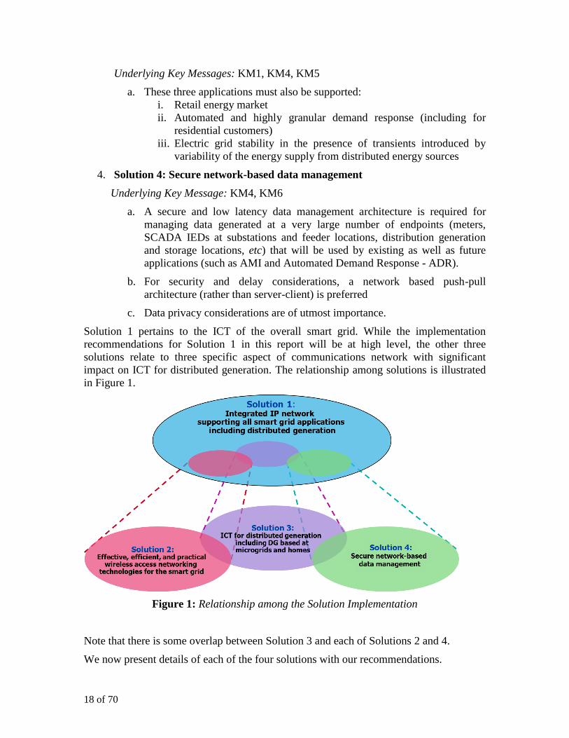
Solution 1 pertains to the ICT of the overall smart grid. While the implementation
recommendations for Solution 1 in this report will be at high level, the other three
solutions relate to three specific aspect of communications network with significant
impact on ICT for distributed generation. The relationship among solutions is illustrated
in Figure 1.
Figure 1: Relationship among the Solution Implementation
Note that there is some overlap between Solution 3 and each of Solutions 2 and 4.
We now present details of each of the four solutions with our recommendations.

19 of 70
5. Integrated Communication Network for the Smart Grid
Currently, communication network needs for most utilities are supported by disparate
networks, each supporting an utility application such as SCADA, physical security
(CCTV), or mobile workforce communication. With smart grid evolution as well as the
expected growth with a large number of new applications, most supporting a large
number of endpoints, creation of a purpose-build network for each application cannot be
sustained. It is extremely important that the utility ICT needs including that of
connectivity to distributed generation are supported by an integrated network. For a
comprehensive discussion on network architecture and design principles for integrated
communication network for smart grid, see [1].
5.1. Smart Grid and Other Applications
In this section some of the application that need to be supported over the integrated
network are presented
5.1.1. Traditional and Current Utility Applications
SCADA is the ubiquitous utility operations telecommunications (OpTel) that is used to
monitor distribution and transmission substation equipment and to control their
operations based on the measurements collected by the substation-based Intelligent
Electronic Devices (IED). Remote Terminal Units (RTU) are a special class of IEDs used
in most existing utility substations to aggregate SCADA traffic. Most utilities deploy (or
lease from carriers) point to point TDM links between the substations and utility Data and
Control Center for that purpose. New standards (such as IEC 68150 [4]) and products are
increasingly supporting SCADA communication over Ethernet and IP including support
for legacy IEDs and communication protocols.
Teleprotection refers to monitoring fault at a substation (X) from another substation (Y)
connected directly to X over a transmission line and taking appropriated action at Y, say
tripping a circuit breaker, when the fault is detected at X. Thus teleprotection requires
communication between these two adjacent transmission substations, so that Y monitor
the fault X. Many protection schemes have three, four, or five endpoints requiring point
to point communication between several pairs of adjoining substations. They need to
work together for the integrity of teleprotection. Due to the extreme nature of this
application (since a fault can result in severe damages), multiple redundant direct
communication connections are provided between the teleprotection equipment at the
substations.
CCTV may be deployed by the utilities at substations and other locations for physical
security. The corresponding video traffic is usually carried to the security management
systems over direct utility-owned or service provider network connections.
Mobile Workforce (WF) voice and data applications may be carried over a variety of
networks. In a few cases, the utility may own and operate Land Mobile Radio (LMR)
networks for the push to talk (PTT) voice communication. For other voice and all data
communication needs, carrier voice and/or wireless mobile networks may be used.
20 of 70
For utility Enterprise Data and Enterprise Voice applications utility-owned or service
provider multi-media networks may be used (often separate networks for voice and data
if VoIP is not used)
5.1.2. New and Evolving Utility Applications including Smart Grid Applications
Distributed Generation including Distributed Electricity Storage and Electric vehicles
require data communication for different applications with these systems as end points.
For monitoring and control of these systems, applications similar to SCADA are used.
Additional data transfer and protocols will be needed for supporting other applications
including Retail Energy Markets, Automated Demand Response, and maintenance of grid
stability. These three applications are briefly describer in Section 3.1 and ICT for these
applications is covered in Section 7. (Also see Figure 1).
Microgrids are a class of prosumers that generally includes more than one building or
dwelling and includes at least one source of energy. The microgrids are self contained in
that, during utility power outage, the microgrid energy sources can provide adequate
power supply to (at least the emergency needs of) consumers in the microgrid. A
microgrid Energy Management System (EMS) manages the microgrid. (Also see Figure
1). In particular, the EMS manages the microgrid connectivity to the utility power grid
and it communicates with the utility systems for energy management. An important
example of an EMS is the energy management system of a large building.
Demand Response (DR) is expected to be one of the important mechanisms in energy
management with the evolution of the smart grid. In addition to the conventional demand
response techniques at macro-level, utilities will use automated demand response (ADR)
that is targeted to even individual dwellings. For details of ICT support of ADR see
Section 7.
Connectivity to home area networks (HAN) is an important aspect of smart grid
evolution in actively incorporating the consumer in energy management. Depending on
the utility policies, the home networks may be allowed to be a part of the utility’s
integrated communication networks either with the connection through the smart meter or
through a “home gateway”
AMI is perhaps the first smart grid application that most utilities have deployed or are in
the process of planning for its introduction. Some utilities are already running AMI trials.
With the promise of smart grid and support for applications like ADR, it is expected that
the smart meters will send interval measurements at a very high frequency (say every 15
minutes), rather that at a very low frequency if billing was the only application supported
by the meters.
Distribution Automation will necessitate SCADA expansion to all utility substations
and to the reclosers/capacitor banks deployed at the distribution feeders.
Synchrophasors are Phasor Measurement Units (PMU) that collect voltage and current
phasor (magnitude and phase angle) measurements at various points in substations. These
measurements are time-stamped with a common clock (derived from GPS). The
frequency of synchrophasor measurements is extremely high – 30, 60, or even 120
measurements per second. (Compare that to the frequency of SCADA measurements –
say, once every 5 seconds).
21 of 70
With the transformation to a high capacity integrated communication network, it will be
cost effective for the utilities to expand their CCTV coverage to additional substations
and additional cameras in a substation, and also support higher resolution images.
Mobile workforce voice and data applications including real time video capture of an
incident can also be migrated to the integrated network rather than being supported by
multiple networks. Migration of the PTT traffic to the integrated network may require
deployment of corresponding gateways if VoIP PTT is not natively available.
5.2. Integrated Communication Network Requirements
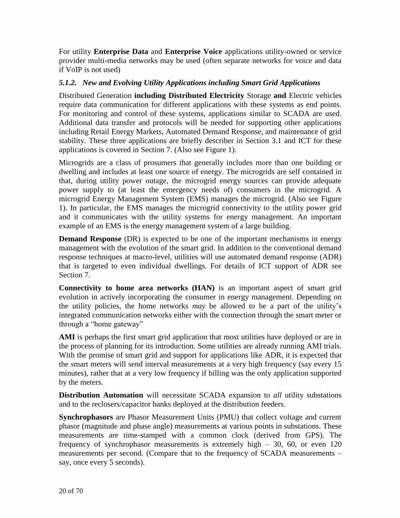
5.2.1. Application Traffic Characterization
Qualitative characterization and performance (delay allowance), reliability, and security
requirements for supporting some of the smart grid and other utility applications over the
integrated communication network are presented in Figure 1. (This table is slight
modification of similar tables presented in [1] and [3]).
Table I: Qualitative Characterization and Requirements of Smart Grid Applications
Application (Domain) Scope
HS (Hub-spoke) or
P2P (Peer to Peer)
Data Rate /
Data Volume
(at endpoint)
(One way)
Latency
Allowance
Relia-
bility Security
SCADA (Transmission,
Distribution) P2P, HS Medium/Low Low High High
Teleprotection (Transmission) P2P High/Low V. Low V. High V. High
DG - Demand Response
(Generation, Distribution,
Prosumers, Consumers)
HS Medium/Low Low High High
DG - Retail Energy Management
(Generation, Prosumers,
Consumers)
HS Medium/Low High High High
Communication with Microgrid
(Prosumers, Consumers) HS, P2P High/Low Low High High
AMI - Interval measurements
(Consumers) HS Low/V. Low High Medium High
Synchrophasors (Transmission) HS High/Low V. Low High High
Distribution Automation
(Distribution) HS, P2P Low/Low Low High High
CCTV (Operations) HS High/Medium Medium High High
Mobile Workforce (Operations) HS Low/Low Low High High
Enterprise data (Business) HS Medium/Low Medium Medium Medium
Enterprise Voice (Business) P2P Low/V. Low Low High Medium
V. High: Very High V. Low: Very Low
For each application, the corresponding domain(s) are provided parenthetically.
Note that the networking requirements for an application may change with underlying
context. For example, for AMI, the QoS, reliability, and security requirements will be
22 of 70
more stringent when the meters are participating in active demand response (as compared
with routine interval measurements)
Most application endpoints generally communicate only with their central control system
(ie, they are hub-spoke connections). In almost all these cases, the upstream (to the
control centers) bandwidth requirement is greater than the downstream (from the control
center). In any case, the data volumes presented by smart grid applications are generally
moderate except perhaps for the CCTV traffic.
5.2.2. Network Performance, Reliability, and Security
Network performance (in particular delay), reliability, and security included in Table I.
differs from those of the carriers and enterprise multimedia data networks since the utility
application require stringent performance(QoS), reliability, and security considerations.
As seen in the table, OpTel mission critical applications such as teleprotection and
SCADA require highly reliable and secure network. In some other cases, requirements
may be relaxed somewhat for an individual endpoint. For example, the network
availability for an individual meter may be relaxed from the reliability of the AMI system
itself. But even in that case, data privacy requires that the connections to the individual
meters must be secure2.
5.2.2.1 Network QoS
The smart grid applications exhibit a very wide variation in their delay and priority
requirements. A comprehensive list of the applications that can be supported over the
integrated utility networks is presented in Appendix A1 with their delay and priority
requirements. (See Table VI which is taken from reference [2]). These applications,
particularly the ones with low delay high priority values, must be afforded individual
QoS treatment in the network.
In most implementations of carrier and enterprise data networks, typically three or four
QoS classes are supported to which traffic from all applications are mapped. (See Figure
12 in Appendix A). Further, the VoIP bearer traffic is considered to be of the highest
priority in these multimedia data networks. But as can be seen from Table VI, there are
many utility applications that have priorities higher and delay allowances lower than the
VoIP traffic. If such data network architecture with only a handful of QoS classes were to
use for the smart grid communications network, many mission critical applications will
need to be mapped to a single class (see Figure 12). in that case, it will be impossible to
guarantee the required QoS for these high priority applications3.
There are some products that support a few more than the typical three or four QoS
classes that can help alleviate the problem to some extent, but not necessarily entirely.
Standards and new products may need to be developed to support QoS for the integrated
2 If utilities in several countries have access to the same data management system, attention must be paid
to the variety of security and privacy laws. In that case the most restrictive rules must be implemented.
3 Note that, this analysis is relevant even if the network does not carry any VoIP traffic. The fact that
traffic for multiple applications is given the same QoS treatment will lead to not supporting the QoS
requirements for the traffic of many of these applications.
23 of 70
utility networks. In [2], a few alternate QoS schemes have been proposed and analyzed,
pending such standards and product development.
5.2.2.2 Network Reliability
The network architecture presented here (Section 5.3) provides for redundant connections
as well as assumes other redundancy provisions in switching and routing
implementations. The network reliability and service availability will need to be
calculated in actual implementation based on the corresponding physical and logical
interconnections, hardware and software reliability, and network configurations. Network
design should include reliability requirements for each application.
Additionally, network diversity including dual homing, disaster recovery and business
continuity, and network resilience requirements must also be incorporated in the design.
Like any other requirement, the network design must strive to achieve the reliability
objectives that meet the cost constraints. For example, sometimes it may be possible to
reduce dependence on redundant physical connections with redundancy in routing.
5.2.2.3 Network Security
Network security requirements must always be a part of the network design process
rather than an afterthought. In addition to the strategic deployment of typical firewalls
and IDS/IPS systems, due attention must be paid to cyber security requirements based on
the utility security policy. While network security (including cyber security) is outside of
the scope of this project, data privacy considerations are analyzed in Section 8.
Comprehensive guidelines on cyber security for the smart grid can be found in [6].
5.2.3. Support for Legacy Systems, Networks, and Protocols
With the ubiquity of IP networking and IP support of many utility applications and
corresponding products, it is expected that IP will be the underlying networking protocol
of the integrated network. It is extremely important to note that IP being the networking
protocol does not imply that the utility network will be over the Internet.
The integrated network must support utility legacy systems, networks, and protocols for a
period of time for many response including costs and extreme reliability and security
requirements of some applications.
Two important cases are presented here.
5.2.3.1 TDM Connectivity
Most existing OpTel applications (including SCADA) use direct Time Division
Multiplexing connectivity between endpoints (such as between an RTU and the SCADA
control systems). While IP SCADA based systems are becoming available, the TDM
connectivity may need to be maintained for a period of time. This is possible in the
integrated IP network by using one or more of the following three options.
1. Tunneling TDM through IP including pseudo-wire connections
2. Circuit emulation (such as E1 emulation over Ethernet)
3. Gateways connecting legacy equipment into the IP network
24 of 70
Further, the utilities may transform their substation networks to comply with the IEC
61850 standards- based [4] LAN architecture of the station bus and process bus. See
Appendix A2 for an example of a substation based on the 61850 architecture with
connectivity to the IP network if needed.
5.2.3.2 Teleprotection
Teleprotection is generally used between high voltage transmission substation, as such
the communication requirements are extreme. The network delay must be maintained
within half a cycle (translating to 10 ms for the 50 Hz electrical system [see Table VI]).
Network reliability is maintained by connecting these adjacent substations over two or
more independent connections – some of technologies used for teleprotection are PLC,
microwave, leased voice grade lines, and optical. Lately, Ethernet technologies are also
being deployed for cyber security.
With IP as the networking protocol of the integrated smart grid communications network,
the current teleprotection schemes may be maintained for a period of time until the
utilities can assure the requirements over the IP network. The possibility of supporting
one of the redundant teleprotection connections through the IP network should be
explored at the earliest opportunity.
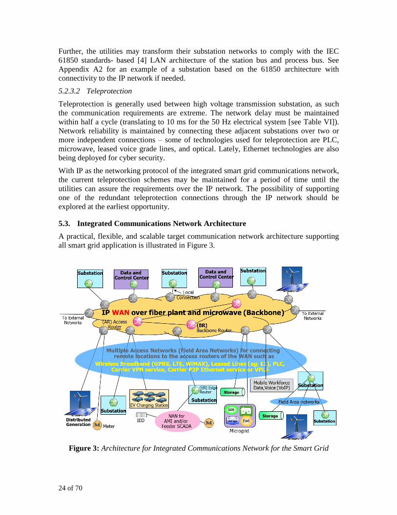
5.3. Integrated Communications Network Architecture
A practical, flexible, and scalable target communication network architecture supporting
all smart grid application is illustrated in Figure 3.
Figure 3: Architecture for Integrated Communications Network for the Smart Grid

25 of 70
As indicated earlier, IP is assumed to be the underlying network protocol for the
integrated network with support for connecting legacy endpoints and protocols (such as
TDM) using tunnels, circuit emulation, and/or gateways.
Given the expanse of the utility service territory, the number of endpoints that need to be
connected into the network, and since communications for most applications are
predominantly between sensors and/or remote endpoints and the central application
control or processing servers, an edge-core network architecture is preferred as illustrated
in Figure 3. Another important aspect of this architecture is traffic aggregation at
intermediate points in the network rather than direct communication between the
endpoints, thus facilitating ease of traffic routing, reliability, QoS implementation, and
reduced costs.
To avoid complexity in the figure, not every possible application or network connectivity
option is included in Figure 3. In any case, the actual physical connections will be
dictated by network design.
While the enterprise voice and data applications or utility enterprise offices are not
included in Figure 3, they can be easily supported by the architecture based on utility’s
preference about integrating the OpTel and business applications on the same network.
5.3.1. Traffic Aggregation at Network Endpoints
An Edge Router (ER) at an endpoint location aggregates traffic from multiple sources
and applications at that location. For a location with a single endpoint or only a few
endpoints, there may not be an ER at that location that aggregates their traffic and these
endpoints mat be connected directly into the network. Depending on network design, an
ER may also be used to aggregate traffic from other locations in the vicinity. For
example, an ER at a (large) substation may aggregate traffic from other (smaller)
substations as well as traffic from other locations in the vicinity, in addition to the traffic
generated at that substation itself. (Also see Figure 13).
5.3.2. Core Network (WAN)
Depending on the network expanse and end points, the core network (sometimes called
WAN – Wide Area Network) may vary from a single router up to a mesh of (redundant)
interconnection of backbone routers (BR) and access routers (AR). ERs not connected to
other ERs and endpoints not connected to an ER connect to the ARs for network
connectivity. Based on the reliability requirement, an endpoint (such as the data and
control center or a “important” substations may connect to two different access routers.
An AR aggregates traffic to/from the endpoints that connect to the ARs, possibly through
the ERs. The WAN must be a reliable network with very high reliability (eg, there must
be at least two physical paths between every pair of ARs). For that purpose additional
routers BRs may be deployed in the core network based on the network design.
Often, the core network will be close to the utility data and control centres as well as to
the substations in metro areas. Thus some of the ARs may be collocated with these utility
sites. For such a collocated site, its endpoints may connect to the corresponding AR over
the LAN in that site. If required for redundancy, ER at this site may additionally connect
to an AR at another location over a FAN.
26 of 70
Based on security policies and security designs, firewalls and IDS/IPS systems are
deployed at ARs and BRs.
In many cases the WAN will be owned and operated by the utility but that may not
always be the case. Even the utility-owned WAN may lease or share basic physical
resources such as fiber plants and spectrum. (See Section 5.4)
Optical fibre is used extensively in the majority of Europe’s TSO companies. However
due to the fact that they link the main electricity generators with the consumers centres,
their capacity to contribute to distributed generation in medium voltage networks is
limited.
Only a small number of DSOs, mainly in Western Europe, have any substantial amount
of optical fibre. Nevertheless most of them think they will need to install in the future as
smart grids deploy, mainly in medium voltage networks. This will contribute to the
deployment of highly reliable, cost efficient and secure networks.
Finally, utilities have been investing in Fibre to the Home (FTH), principally in the north
of Europe (e.g. Sweden and Denmark). However the investors tend to be municipal
utilities bundling high capacity broadband, triple play services and smart meter solutions.
5.3.3. Access Networks (FANs)
Access networks (often called Field Area Networks – FANs) provide connections
between utility locations and the ARs. After presenting a brief overview of the wireline
and wireless FANs, we present a few more details on the Power Line Communication
(PLC) technology which is being increasingly used in smart metering access and being
explored for deployment in FANs including connectivity to DG.
All of Section 6 deals with the wireless FANs.
5.3.3.1 A Brief overview of wireline and wireless FANs
The utility may use multiple wireline and wireless technologies for FANs4. The FANs
may be owned and operated by the utility (self-provided) or service provider networks
may be used as FANs. Wireline technologies include PLC, private lines, Layer 2
technologies as Ethernet and Frame Relay, and MPLS VPN service. The wireless
broadband technologies include GPRS and HSPA with a migration path to LTE and
WiMAX. Wireless technologies are discussed in detail in Section 6.
The mix of utility-owned and service provider network FANs depends on the service
level agreements (SLA) provided by the service provider networks consistent with utility
requirements, networking technology availability in an area, costs and other
considerations. The choice of FAN technologies and ownership mix can evolve over time
depending on the emergence of new technologies, utility access to spectrum, and network
expansion with new applications and endpoints.
4 A comprehensive review of wireless ad wireline technologies that are FAN candidates can be found in
Appendix 1 of the work package 2 deliverable (WP2) of this ICT4SMARTDG project [8].

27 of 70
While strictly not FANs, and based on AMI communication technology, local
Neighborhood Area Networks (NAN) such as over 2.4 GHz or 900 MHz RF mesh over
unlicensed spectrum or over PLC may be used for concentrating smart meter traffic at
substations or near distribution transformers. The NANs may also be used for
concentrating the SCADA traffic from the IED deployed over feeders to RTU/IED in the
substation. Note that meters and feeder IEDs may also directly connect to the ARs,
depending on the vendor product communication technologies.
5.3.3.2 Power Line Communication
Power Line Communication (PLC) has been envisioned by many as the most adequate
communications technology for Smart Grid deployments. Some others have also been
skeptical about the possibilities of PLC as a good candidate for the purposes of data
transmission over electricity grids [15]. For a comprehensive tutorial on PLC technology
and its use in smart grid communication networks, see [7].
Power Line Communication over the power lines themselves as communication medium
has been in use since early 20th
century, initially for voice communication. In the last fifty
years or so, PLC was also used for low data rare communication over HV and MV lines5
for applications such as teleprotection and SCADA. PLC was not considered a useful
technology by many for data communication because of its low range, susceptibility for
interference with other communication applications, costly solutions to overcome the
problem of communication through transformers (requiring coupling equipment to
bypass transformers), and very low data rates.
However lately, PLC technology has taken its roots in smart grid evolution as one of two
Neighborhood Area Networking (NAN) technologies for AMI (See Section 6.1.1). In the
last several years, many countries (particularly in Europe) are looking to deploy PLC
FANs connecting to DG, meter concentrators, and other smart grid endpoints. Many
standards bodies and industry forums have developed and are developing standards for
supporting PLC communication. PLC is also considered an important technology for the
“last mile” component in the Broadband Power Line (BPL) communication for the
Internet access.
Table II provides a comparison for different PLC technologies and a few key standards
that support these choices: many of these standards are still being developed.
Table II: Comparison of PLC Technologies
Smart Grid
Applications UNB-PLC
(30 Hz – 3 kHz)
Low Data Rate
NB-PLC
3kHz-500 kHz
Low Data Rate
NB-PLC
(3kHz-500kHz)
High Data Rate
BB-PLC (1.8 MHz – 250
MHz) Key Standards
5 There are varied definitions of what are considered high voltage (HV), typically used for transmission,
medium voltage (MV), typically used for distribution, and low voltage (LV) typically used for
connecting the distribution transformers (MV/LV transformers) to homes and most commercial
establishments. Many of these definitions are country-specific. IEC Technical Report 61000-3-6
provides the following ranges for these voltages: HV: > 35 kV and ≤ 230 kV; MV: >1 kV and ≤ 35
kV, and LV: ≤ 1 kV. Also extra high voltage (EHV) is > 230 kV.

28 of 70
(120 bps) (few kbps) ( 500 kbps) V. High Data Rates
(up to several
hundred Mbps)
LV-PLC
AMR, AMI,
Load control
AMI,
HomePlug AMI, FANs Internet access
TWACS IEC 14908-3,
IEC 61334
IEEE 1901.2,
PRIME,
G3-PLC
IEEE 1901,
IUT-T G,hn
MV-PLC (FANs for) SCADA, DG, etc Internet access
HV-PLC Teleprotection, Teleprotection, SCADA, PMU
IEC 60495 IEC TC57 / WG20
UNB: Ultra Narrowband NB: Narrowband BB: Broadband
Most LV-PLC AMI implementations in Europe are based on G3-PLC standards
developed by a global partnership of utilities and other stake-holders led by ERDF in
France and the PRIME by Iberdrola. This is being driven by the need to implement 80%
smart meters by 2020 (mandated by the European Commission’s 3rd energy package).
these and many other high data rate standards are based on Orthogonal Frequency
Division Multiplexing (OFDM) for modulation.
High data rate LV-PLC (or BPL) is targeted at LV smart grid applications, such as DG,
EVs, DR, etc. There are few standards, but there is distinct interest around Europe for
these technologies. It was dismissed historically in the power industry, since it was
addressing the internet market and it had technology flaws, However, now this
technology is seen as one of the few viable methods of connecting to smart grid
applications in the LV network. There are small scale pilot projects in Europe trialing this
technology.
There are a number of small implementations of high data rate MV PLC (including BB).
This area is getting at lot of interest, since it is a promising FAN technology. We have
included an example of a new PLC FAN network below.
Power Line Communications in Iberdrola Smart Grid Deployment:
Iberdrola has been planning its Smart Grid deployment since 2007, when the Spanish
Government issued legislation mandating that regular electromechanical meters should
be substituted by other meters with advanced metering functions, and the possibility of
being remotely accessed for operating (remote connection / disconnection) and reading
purposes. Faced with this challenge, Iberdrola designed its Smart Grid strategy and
decided the scope of this concept in real field implementations with available systems
and technology. From the telecommunications perspective, Smart Metering was the
driver to take advantage of the need to develop a network for Smart Metering purposes,
to make it Smart Grid capable.
29 of 70
Iberdrola finished its first Smart Grid deployment in Castellon (Spain) in 2011, with more
than 100,000 points of supply, and more than 600 Secondary Substations (SS’s), and
today it is fully operational.
The network architecture concept is based in the creation of broadband PLC (BPL [18])
extended domain local area networks to interconnect SS’s which would rely on a certain
number of backbone connections towards central systems (non PLC technologies of
various kinds, both private and public), and narrowband PLC (CENELEC A band,
PRIME) communications towards meters by means of gateways in SS’s.
PLC (broadband, BPL) plays a preeminent role to connect SS’s among them. PLC in
Medium Voltage (MV) networks enables the creation of layer 2 networks, with speeds in
tens of Mbps, and able to overcome different electricity grid conditions. 50% of the
deployed telecommunication solutions for SS’s are connected in Castellon through BPL.
PLC (narrowband CENELEC A band, PRIME [19]) plays a principal role for meter
(point of supply) access. PLC in Low Voltage grids, i.e., PRIME, enables the connection
of all meters to their SS’s for meter remote control and reading purposes. 100% of the
meters deployed in Castellon are PRIME meters.
5.3.4. Highlights of the Edge-Core Architecture
Some of the highlights of the edge core architecture:
AR – ER architecture provides common framework for incorporating disparate
access technologies
Efficient traffic routing through the ARs
Efficient implementation of end-to-end QoS providing application-specific QoS at
ARs, BRs, and ERs over inks carrying traffic for multiple applications.
Flexibility in introducing new applications and/or adding new endpoints, often
without any design changes, bandwidth expansion or reconfigurations – the
endpoints/ERs simply connect to the “nearest” ERs. This shows the high degree
of scalability in the architecture definition. Note that when there is a need for
adding a very large number of endpoints to the network after new application
introduction, that is a problem of general capacity management.
With technological advances in configuration management, even plug-and-play is
possible for configuring a new endpoint into the network.
In future, if distribution automation required distributed SCADA management
from the substation, the architecture can easily provide the corresponding
connectivity and routing.
The architecture is highly leveraged in that the WAN supports all applications
over protocol-agnostic WAN
Support for end-to-end TDM connection through tunnels, circuit emulation, and
protocol gateways.
30 of 70
If the utility decides to deploy its enterprise voice (VoIP) and data applications on
the integrated network, the architecture readily supports such convergence.
The architecture is readily amenable to incorporate MPLS technology. MPLS
provides addition advantages in network resilience, traffic engineering, and
support of multiple L1, L2, and L3 protocols over the same IP connections. In
particular, the MPLS pseudo wires support multiple protocols including TDM and
Ethernet. The utility may also use MPLS VPN to divide its endpoints and
applications into closed user group. Traffic isolation inherent in simultaneous
independent connections through MPLS further facilitates security
implementations.
Even if the architecture is basically a core-edge architecture, based on network
design, links between endpoint locations (say, between substations) may be used
for additional reliability and route diversity. For example, the existing links
between substations used for teleprotection may carry traffic for other
applications, after configuring for proper isolation between the traffic of multiple
applications and/or enhanced QoS as discussed in Appendix A1.
(Not shown in the architecture figure) the architecture allows connectivity to
microgrids, HANs, or energy management LANs of commercial customers
depending on regulatory compliance requirements and only if necessary security
devices and processes are implemented.
Based on need and maturity of available technology, support of IPv6 will need to
be considered. In any case, it must be possible to continue to use the existing
networks and addresses based on IPv4 when migration to IPv6 begins.
5.4. Network Ownership
There are many benefits to utility ownership of the communication network assets and
operations, particularly if the networking costs are manageable. There are advantages of
using service provider network(s), particularly if the service providers can provide SLAs
consistent with utility requirements for at least the mission critical applications. Here is a
comparative analysis of benefits of all utility self-provided network and all service
provider networks:
A Case for Private (Utility-self provided) Network6
Exclusive, timely, and efficient control of utility mission critical applications and
restoration
Effective regulatory compliance of security and reliability standards
Utility application requirements (performance, reliability, and security) are
different and more stringent than those for the typical customers of the service
provider networks
6 The physical assets such as fiber and spectrum may be shared with other utilities or companies.
Further, point-to-point L1 (such as TDM private lines) and even L2 (such as Ethernet and Frame
Relay) connectivity may be provided by service providers
31 of 70
Generally, one service provider may not be able to support all smart grid
applications. But multiple service providers add to complexity in networking and
utility oversight.
Consistency in network management and operations based on utility policies.
A Case for Public (Carrier) Networks
Lower capital expense for utility
Competition among service providers may reduce total costs to the utility
Frequent technology upgrades in service provider networks provide new
capabilities quickly and at lower costs. Utilities may not refresh their self-
provided networks as often.
Utilities may not possess the expertise required for state of the art communication
networking.
Service provider network is the default option if network spectrum is not available
to the utility
There is no clear recommendation that will suit all utilities. The mix of these two types of
networks will depend on costs, SLAs, technology availability, and locations. Typically,
the WAN will be a utility self provided network in most parts of the utility territory. The
FANs will be a mix of both types of networks with the mix changing based on
availability of new technologies and introduction of new applications. For wireless
networking technologies this issue will be revisited in Section 6.
5.5. Communication Network Transformation
In this section we present a high level evolution plan for network transformation from the
disparate purpose-built communication networks to a target network architecture that will
be the integrated IP network supporting all utility applications. Certainly, the evolution
steps presented in this section can only be at a high level for guidance. The details and
their execution will vary with each utility and its objectives.
5.5.1. Planning Network Transformation
Network transformation planning may take 6 months to a year.
1. Begin with a target communications network architecture. The network
architecture of Figure 3 can be a starting point, but the network architecture must
take into account the present utility network assets, expected expansion of these
assets, smart grid objectives, and the planning horizon for network transformation.
While no major changes can be expected in the target network architecture, it
should be a living document with possible marginal modifications based on
unplanned growth, unanticipated technology changes, and major changes in utility
application requirements
2. Create a high level network design right at the beginning. This design should
included physical and logical interconnections based on the network growth and
traffic expected as the utility adds smart grid applications and the corresponding
network endpoints. (Being a high level design, it may not include IP addressing,
32 of 70
details of routing, network element specification and configurations details, and
other details). In particular, the design should provide the locations and high level
generic configurations of access routers and the backbone routers
Certainly at every stage of network implementation, a detailed design for that
implementation will be required.
3. Plan modernization of the utility networking assets – particularly the fiber and
microwave assets (if any) that will form the major part of the core network.
Among other things, such modernization will included migrating from TDM to IP
over, say, Ethernet over DWDM, and may also include IP/MPLS implementation
for support of high performance highly available converged network.
4. Plan expansion of the core network to cover as many utility locations (particularly
the substations) as possible. The actual expansion activity at each stage will
balance expansion costs against access network costs for connecting the remote
endpoints.
5. Prepare the access network strategy for both the wireline FANs and wireless
FANs. Due to the uncertainties in availability and introduction of wireless
technologies. a wireless blueprint may need to be created as described in Section
6.2.
Note that this planning process will create a master plan for network transformation that
must be kept up to date through network transformation.
5.5.2. Early Years of Network Transformation
Depending on the planning horizon, the following activities should be undertaken during
the first 2-5 years of network transformation
1. Deploy access routers and backbone routers and start building the core network
2. Determine the FAN technologies and access networks that will be used initially,
including both utility-owned as well as the carrier networks. Deploy/contract/lease
these FANS if they are not already connected.
3. Connect the existing utility endpoints and applications to the ARs over the access
networks (FANs). Based on network design, some of the endpoints may be
connected to intermediate locations (such as large substation routers) for local
traffic aggregation.
4. Modernize fiber plant and microwave network. Begin expansion of the fiber and
microwave network
5. Begin migrating the mobile workforce traffic to the integrated network.
5.5.3. Throughout Network Transformation years
Depending on the utility, the network evolution to the target architecture may take 5-20
years.
1. As new (smart grid) applications are introduced, connect the corresponding
endpoints to the network and/or add these new applications to the existing
endpoints as appropriate. In most cases, network capacity expansion may not be

33 of 70
necessary as application endpoints are gradually added to the network. However,
in some cases, major network capacity enhancements and expansion may be
necessary.
2. Periodically determine the proper mix of FANs that must be supported for access,
necessitating retiring or removal of some of the FANs and addition of new FANs.
3. Monitoring for network capacity should be an ongoing activity with capacity
additions as necessary.
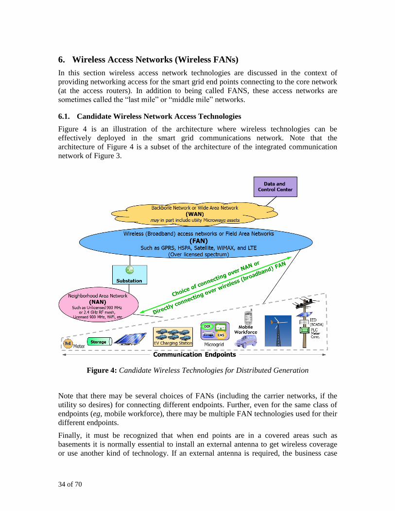
34 of 70
6. Wireless Access Networks (Wireless FANs)
In this section wireless access network technologies are discussed in the context of
providing networking access for the smart grid end points connecting to the core network
(at the access routers). In addition to being called FANS, these access networks are
sometimes called the “last mile” or “middle mile” networks.
6.1. Candidate Wireless Network Access Technologies
Figure 4 is an illustration of the architecture where wireless technologies can be
effectively deployed in the smart grid communications network. Note that the
architecture of Figure 4 is a subset of the architecture of the integrated communication
network of Figure 3.
Figure 4: Candidate Wireless Technologies for Distributed Generation
Note that there may be several choices of FANs (including the carrier networks, if the
utility so desires) for connecting different endpoints. Further, even for the same class of
endpoints (eg, mobile workforce), there may be multiple FAN technologies used for their
different endpoints.
Finally, it must be recognized that when end points are in a covered areas such as
basements it is normally essential to install an external antenna to get wireless coverage
or use another kind of technology. If an external antenna is required, the business case

35 of 70
could become negative due to the additional personnel costs when installing the devices.
A way to minimize the costs so when using wireless e.g., using GSM, is to ensure that
only one person does the entire process: installing the meter and switching on the
communication.
6.1.1. Smart Grid Endpoints connecting to Wireless Access Networks
There are many situations where there is little choice but to use the wireless networking
technologies such as for mobile workforce communication, and connecting to remote
endpoints where proving wireline access to isolated building, distributed generation
location, or IEDs located on the feeders is cost-prohibitive. But even for consumer
locations otherwise connected to wireline network such as to GPON or HFC (say for their
Internet access), the utility may be reluctant to connect its meters or IEDs to these carrier
(service provider) networks or access the distributed generation facilities over these
networks. Note that, often the cost of deploying utility-owned wireline networks only for
utility operations traffic is cost-prohibitive.
While any smart grid endpoints including a substation or utility office may use wireless
access network, we concentrate on the following four classes of smart grid endpoints that
are the most probable candidates requiring wireless access to the core network.
1. Depending on the size of the utility, there may be several million smart meters
deployed at all consumer locations. There are three different classes of AMI
implementations that may use wireless access technologies.
a. Meters communicating with the meter concentrators over an RF mesh
NAN. Meter concentration of an many as 10,000 – 12,000 have been
achieved. The meter concentrator then connects to the meter data
management system (MDMS) through the substation router (ER). MDMS
is generally located at the utility Data and Control Center
b. Meters communicating over PLC with meter concentrators located at the
(the secondary of the) distribution transformer. Meter concentration of up
to 100 is used depending on the number of consumers connected to the
transformer. The PLC meter concentrator in turn may use wireless FAN to
connect to the MDMS. PLC technology was described earlier in Section
5.3.3.2.
c. Meters communicating directly and individually with the MDMS over the
wireless FAN.
2. Distributed generation, storage, electric vehicles, and electric vehicle charging
stations may add up to hundreds of thousands of additional endpoints depending
on the utility expanse. While many of these endpoints may be located at homes
and businesses, there may be stand-alone distributed generation, storage, and
charging stations throughout the utility coverage area.
3. With the advances in distribution automation, utilities are deploying SCADA IEDs
at recloser and transformer locations at the distribution feeders outside of the
substations. This may add tens of thousands of endpoints requiring wireless access.

36 of 70
4. Mobile workforce endpoints for their voice and data communication. It is assumed
that in the near future, all mobile workforce voice communication (including push-
to-talk) will be VoIP by either using VoIP switches or VoIP gateways supporting
the legacy equipment.
6.1.2. Neighborhood Area Networks (NAN)
Wireless Neighborhood Area networks generally refer to RF mesh over unlicensed
spectrum including 2.4 GHz and 900 MHz. These RF technologies are also standardized
in IEEE 802.15.4. However, many implementations do not necessarily follow the
standards exactly such as the ZigBee networking products and many AMI products over
900 MHz RF mesh. Many utilities are also deploying NANs based on Wifi.
The main advantage of these wireless NAN technologies is that the spectrum is free. But
that is also one of the main disadvantages since the utility traffic is subject to interference
from other users of the spectrum. Interference and other factors also limit the range for a
hop of the mesh to about 500 m unless antennas at higher levels are deployed (such as on
the rooftops or poles). While RF radios with data rates as high as 19.2 kbps are used, the
effective data rate is reduced considerably with the number of hops the packets must
travel.
NANs have been used mostly for AMI with meter concentrators at the substations. In
some cases they have also been used for distribution automation with the feeder IED
SCADA traffic being aggregated at the substations. But in many case, these IEDs directly
communicate over the FANs.
AMI communication over unlicensed frequencies are prone to interference with other
applications using the same frequency affecting both the AMI and the other service
applications including those pertaining to other critical applications such as
communications in a hospital environment.
6.1.3. Wireless Access Networks or FANs
The wireless access technologies that are most suitable for smart grid evolution are those
that provide high speed broadband wireless access over licensed spectrum. Depending on
the availability of the spectrum to utilities, feasibility of carrier (service provider)
broadband networks support for smart grid applications, and the emergence of very high
speed new technologies, many choices are possible. These are listed in Table III.
Also See Appendix 1 of the WP2 report of this ICT4SMARTDG project, [8] for a
comprehensive discussion of these technologies. In fact, Table III below has been derived
reproduced from the corresponding Table 1 in [8].

37 of 70
Table III: High Speed Broadband Wireless Technologies
WCDMA HSPA R6 HSPA
R7/8 WiMAX
i (FDD)LTE
ii TD-LTE
iii
Peak data rate
(DL/UL:[Mbps]) 0.4/0.4 14/5.7 43
iii/11.5 40/10 173/58
45/14
Latency
[ms] 100-200 40-60 25-35 30-50 10-20
10-20
Bandwidth
[MHz] (2x) 5 (2x) 5 (2x) 5
5-10
unpaired
(TDD)
(2x) 1.4-20
1.4-20
unpaired
(TDD)
Spectral Efficiency
DL/UL
[Mbps/MHz/cell]
0.2/0.2 0.53/0.3 1.3/4 1.4/0/6 1.8/0.9 1.8/0.9
Architecture RNC-based RNC-based RNC-based Flat IP Flat IP Flat IP
i. WiMAX with 2X2 MIMO @ 10 MHz TDD DL/UL ratio: 29/18
ii. LTE with 2X@ MIMO @20 MHz
iii. TDD LTE with 2X2 MIMO @10MHz
While wireless technologies like GPRS and CDMA 2000 EvDO Rev A are currently
being used by many utilities for their wireless data communication, it is imperative that
they plan for use of the new and emerging wireless technologies listed in Table III.
Technologies like WiMAX and LTE are natively IP technologies that provide end to end
IP connectivity at very high speed. LTE is the most promising technology being adopted
by many carriers and is being planned to be used by mission critical services in several
countries. For supporting only the smart grid traffic, it is not even necessary to use 20
MHz spectrum. A 3-sector antenna in 5 MHz bandwidth can support more that 5 Mbps
UL data rate that will be shown to be more that adequate for most smart grid traffic
covered by an LTE base station. (See 6.3.3 as well as reference [9]).
The discussion of wireless access networks cannot be complete without the inclusion of
the Satellite communication – based access networks. Utilities have used satellite
communication for a long time for substation and mobile WF communication in the
remote areas where other forms of communication were not possible. Today, satellite
communications has undergone a major transformation and has evolved in improving
performance, reliability and in reducing costs. Satellite networks are now two-way
communications systems, built on IP, with broadband data rates. Next-generation coding
standards have made satellite more reliable and cost efficient. Further, satellite
networking hardware has been engineered to meet next-generation carrier standards,
integrating well with terrestrial wireless and wireline communications.
Thus if the delay requirements of the utility applications (see Table V) can be satisfied,
satellite communication can be an alternative for access networks, particularly for
endpoints in areas where other forms of communication are not feasible. Some of these
applications are AMI (particularly from the meter concentrators), DG, CCTV, and mobile
WF. In a few cases, even SCADA and distribution automation application in remote
38 of 70
endpoints will need to use satellite communication in spite of the delays if no other form
of communication is possible.
6.2. A Blueprint for Wireless Access Network Evolution
It is necessary for a utility to prepare a plan (or a blueprint) for the evolution of wireless
access networks as the need for broadband wireless technologies increases and newer
wireless technologies become very attractive - but access to these technologies are
difficult to acquire due to unavailability of the spectrum. Essential tasks of preparing such
a blueprint are:
1. Prepare an inventory of the wireless technologies and the corresponding NANs
and FANs that are currently used across the utility. Evaluate these technologies for
their possible use to support additional applications on one hand and possibly
retiring them on the other due to their inadequacies to support even the current
applications and traffic.
2. Develop cost-benefit analysis of the approaches to select candidate technologies
for replication across the utility. Leasing or contracting for carrier networks and
services should not be discarded summarily; instead their inclusion should be
carefully considered, subject to satisfactory SLA guarantees for a period of time.
3. Where possible, use the same wireless NAN or FAN for supporting multiple
emerging applications such as AMI and distribution automation.
4. The utility may already be running smart grid pilots for AMI, distributed
automation, and/or electric vehicles over wireless networks. Additionally the
utility may have access to outside pilot projects. It is important that the results of
these pilots and lessons learnt from these pilots are included in preparing the
blueprint. Estimate costs for extending wireless networks used in these pilots for
deploying these applications and extending the wireless networks across the utility.
5. While it is very difficult for the utilities to get access to spectrum for deploying the
broadband technologies of Table III, there are some products, particularly the
WiMAX products that may be deployed in unlicensed or “lightly licensed”
spectrum with minimal spectrum costs. Their deployment may be considered for a
short period of time to provide high speed wireless FANs expediently.
6. The utility must engage in efforts undertaken by European UTC and other industry
forums to acquire spectrum that can be allocated exclusively for the use of utility
or spectrum that may be shared with other mission critical services such as public
safety. While much of the new spectrum is auctioned by the national governments
for use by carriers to offer high speed broadband services, there are instances
where the government has dedicated a part of the spectrum for mission critical
services such as the for public safety in USA in the 700 MHz band.
7. It is possible to develop technologies where mission critical services like the
utilities can subscribe to carrier broadband services and get priorities for its
mission critical applications traffic when needed. Such resource allocation with
carrier services and networks must be explored.
See Appendix B2 for a discussion on wireless network sharing options

39 of 70
6.3. A Case for LTE
The discussion on wireless access technologies cannot be complete without making a
case for use of the promising LTE (Long Term Evolution) technology, if and when it is
available for smart grid. LTE is rapidly gaining global market acceptance as the leading
4G mobile broadband system. LTE most probably will become a preferred choice also for
utilities to address their communication needs.
6.3.1. Driving forces
Scalability: LTE with its flat IP based radio and core network architecture is well suited
to scale to the utilities traffic needs, no matter how large or small they may be. Given
LTE’s design origin as high performance mobile broadband (MBB) system, there are
certainly no inherent architectural limits to scale upwards to high traffic densities.
Converged IP-platform: LTE’s design as IP packet-only system, together with its QoS
mechanism allows carrying and protecting the diverse traffic flows, all in one system.
VoIP and video / multimedia traffic related to workforce management in the field can
gracefully co-exist with machine to machine traffic from SCADA IEDs to Distribution
Control Center. LTE provides an opportunity for utilities to evolve their existing legacy
narrowband communication systems into one IP-based broadband wireless system,
providing reduced operations expenses.
Future-proof eco-system: LTE has established itself as the leading global standard and
platform for IP optimized radio communications. All major mobile standards such as
GSM, WCDMA and cdma2000 converged into the LTE IP based platform. Further,
established radio standards for mission critical radios will evolve their next generation
standard towards LTE. Such a large base of support ensures ample choice of competitive
standardized equipment, both for networks as well as radio modems (and modules) for
meters and IEDs. Utilities will benefit from this with lower capital expenses, reduced
risks from stranded assets and vendor lock-in as well as a longer lifespan of their
equipment.
6.3.2. Scalability of LTE
It is vital that the technologies chosen today have the ability to scale with smart grid
evolution to meet these demands. They must possess flexible network topologies and
element architectures to adapt to a large set of present and yet unforeseen traffic flows in
the smart grid. Expensive replacement cycles of radio technologies which have become
inadequate to deal with growing traffic and service demands is something utilities wish to
avoid.
LTE technology is ready to meet the reliability and security requirements of smart grid
applications in Table I as well as the delay and priority requirements of the mission
critical applications such as SCADA, Synchrophasors, and push to talk. (See Appendix
A1 and Table VI) LTE’s open ended upward scalability gives the utility the confidence
that the communications will not become any bottleneck in implementing smart grid
functionality throughout the power system.
The LTE air interface differs markedly from narrowband legacy technology. Advanced
Orthogonal Frequency Division Multiplexing (OFDM) technologies work robustly in
severe multipath environments while achieving outstanding radio performance in terms

40 of 70
of radio the options, 1.4, 3, 5, 10, 15, 20 MHz, addressing a wide range of spectrum
arrangements and future growth scenarios. For example, should an utility have initially
access to only a smaller slice of spectrum, it could deploy 5 MHz LTE and have the
option to upgrade to 10 MHz LTE at a later stage with increasing traffic and spectrum
availability. FDD and TDD modes are part of the same standard which allows LTE to
leverage the same technology base for both paired as well as unpaired bands.
Peak data rates of 150 Mbps are commercially available as of today and will evolve in
forthcoming versions of the LTE standard into the Gbps range. This makes LTE a very
robust platform to address any foreseeable bandwidth requirements in utility
communications. And this includes use cases requiring broadband services such as
workforce management using multimedia in the field and wireless video security
surveillance. With LTE utilities have even the option to offer highly competitive mobile
broadband services, should their license permit them to do so, thus leveraging a single
infrastructure to lower operations and capital costs.
6.3.3. Bandwidth Requirements in an LTE Macro Cell
Bandwidth requirements in LTE macrocells has been estimated in [9] taking into account
expected smart grid traffic during normal operations and during critical grid incidents
such as an outage, and the typical range of LTE macrocells in coverage-limited
deployments.
Figure 5 shows the reference architecture for computing the smart grid applications
bandwidth requirements for application endpoints in the coverage area of a single
wireless base station (eNB) in an LTE network.
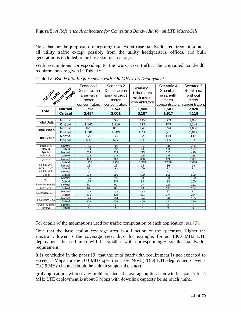
41 of 70
Figure 5: A Reference Architecture for Computing Bandwidth for an LTE MacroCell
Note that for the purpose of computing the “worst-case bandwidth requirement, almost
all utility traffic except possibly from the utility headquarters, offices, and bulk
generation is included in the base station coverage.
With assumptions corresponding to the worst case traffic, the computed bandwidth
requirements are given in Table IV.
Table IV: Bandwidth Requirements with 700 MHz LTE Deployment
Scenario 1
Dense Urban
area with
meter
concentrators
Scenario 2
Dense Urban
area without
meter
concentrators
Scenario 3
Urban area
with meter
concentrators
Scenario 4
Subarban
area with
meter
concentrators
Scenario 5
Rural area
without
meter
concentratorsNormal 1,703 1,747 1,566 1,601 2,820
Critical 3,487 3,601 3,167 2,917 4,118
Normal 748 793 612 663 1,056
Critical 1,102 1,216 879 773 1,149
Normal 826 826 826 826 1,651
Critical 1,789 1,789 1,789 1,789 2,614
Normal 129 129 129 113 113
Critical 597 597 500 355 355
Normal 165 165 95 140 236
Critical 138 138 79 116 197Normal 213 213 213 213 426
Critical 178 178 178 178 355
Normal 826 826 826 826 1,651
Critical 1,238 1,238 1,238 1,238 2,064Normal 16 16 16 16 16Critical 161 161 129 81 81Normal 0 0 0 0 0
Critical 550 550 550 550 550
Normal 165 210 83 83 120
Critical 165 279 83 83 160
Normal 80 80 97 129 161
Critical 67 67 80 107 134
Normal 113 113 113 97 97
Critical 435 435 371 274 274
Normal 124 124 124 96 105Critical 554 554 459 287 296
Normal 0 0 0 3 8Critical 0 0 0 3 7
Enterprise Data
700
MHz
Traffi
c
Req
uirem
ents
(kbps)
Total Data
Total Video
Total VoIP
Mobile WF
(video)
Mobile WF
(PTT - VoIP)
AMI
New Smart Grid
Elements
Dynamic Line
Rating
Enterprise VoIP
Total
Traditional
SCADASynchr-
ophasors
CCTV
For details of the assumptions used for traffic computation of each application, see [9].
Note that the base station coverage area is a function of the spectrum. Higher the
spectrum, lower is the coverage area; thus, for example, for an 1800 MHz LTE
deployment the cell area will be smaller with correspondingly smaller bandwidth
requirement.
It is concluded in the paper [9] that the total bandwidth requirement is not expected to
exceed 5 Mbps for the 700 MHz spectrum case Most (FDD) LTE deployments over a
(2x) 5 MHz channel should be able to support the smart
grid applications without any problem, since the average uplink bandwidth capacity for 5
MHz LTE deployment is about 9 Mbps with downlink capacity being much higher.

42 of 70
7. Distributed Generation-specific ICT Considerations
As indicated in the beginning of the document, ICT for distributed generation is an
integral part of the ICT for the overall smart grid. However, there are ICT considerations
that are unique to DG. In this section three specific DG applications are considered: retail
energy markets, demand response, and grid stability.
7.1. ICT Requirements
Delay and priority characteristics for these three applications are shown in Table V which
is derived from the more comprehensive Table VI for most of the smart grid applications.
Table V: Delay and Priority Characteristics of Distributed Generation Applications
APPLICATION
Number of
communication
network
endpoints
Delay
Allowance
(one way
packet)
Relative
Priority*
Delay Allowance
(To complete an
end-to-end
transaction)
Retail Energy Market Thousands to
several million 1,000 ms 85
5-30
minutes
Automated and granular
Demand response
Thousands to
several million 300 ms 75 Several minutes
Grid stability
Thousands to
several hundreds
of thousand
100 ms 25** Several hundred
milliseconds
* 0-highest priority; 100-lowest priority. Priorities taken from the Table VI in Appendix A. Also
see [2].
** Except that some protection applications may require priority of 10 and one way packet delay
of 10-20 ms
It is thus imperative that the QoS implementation of the integrated IP network support
these performance requirements of the traffic of these applications.
Note the expected growth in the number of endpoints that must be connected into the
smart grid with distributed generation and their importance to efficient energy
management both in terms of energy markets and demand response which are both the
basic tenets of smart grid evolution. Certainly, inclusion of widespread DG requires that
grid stability be maintained in the presence of connecting these generating sources that
are not directly under the utility control.
7.2. ICT for Retail Energy Market
Types and locations of many distributed generation entities are identified in Figure 6.

43 of 70
Figure 6: Architecture for the Retail Energy Markets with Distributed Generation
All generation sources except for the traditional bulk power generation (based on coal,
nuclear, large hydro and others) are considered DG here. Some of the DG are renewable
(solar, wind, tide, etc) but others are not (fuel cell, CHP, etc). Also some of the consumer
locations behave as a power producer and well as consumer. They are called prosumers.
For example, microgrid and electric vehicle are prosumers. Microgrid is a power system
that has at least one energy source (often called DER: distributed energy resource). to
serve its internal load (at least during utility power outage) and thus can perform
intentional islanding in the electrical distribution system. In a normal mode, microgrid is
connected to the power grid and can import/export power from/to the power grid.
However, when there is disturbance in the distribution network, it can operate
independently of the power grid. Similarly, electric vehicle can supply/draw power
to/from the grid and provide ancillary services. EV is an attractive solution to provide
very responsive ancillary service in supplying or drawing power to/from the grid in an
order of second time scale.
7.2.1. Traditional market models with bulk power generators
We consider a market model where DG, including microgrids, DR providers, EVs,
prosumers, want to participate in the energy market. The main interest is to predict the
market behaviors when there are a large number of small scale DG. The number of
market participants can be substantially large.

44 of 70
Traditionally, most market models were focused on a small number of bulk power
generators, often called the oligopoly market (ie a market controlled by only a few
participants) .
Mathematical models for such market have shown, and it is fairly well known, that in a
competitive market, each generator takes its supply function as the inverse of the
marginal generation cost and behaves as a price-taker to maximize its profit, which in
turn also minimizes total societal power generation cost. In this case, the market is called
efficient. However, with the traditional electricity market being an oligopoly with only a
few generators, each participant does not behave as a price-taker but behaves as a price-
anticipator to maximize its own profit by exercising market power.
This is why there has been much research on the modeling of supply functions rather than
the form of the inverse of the marginal cost, and its impact on Nash equilibrium. After the
seminal work of Klemperer about supply function under demand uncertainty, and its
application to British electricity market by Green, supply function equilibrium model has
been widely used to understand the behaviors of generators in an oligopoly market. See
[10] for a brief description of these models. Basically, generators provide the operator
with tuples of quantities of power and associated prices, for all possible price values, and
the operator computes the market clearing price based on demand. Affine or linear supply
function was mainly used for this purpose. To further reduce the possibility of exercising
market power, parameterized supply function was proposed to limit the degree of
freedom of generators.
7.2.2. Two-stage market model with aggregators
Unlike the traditional approach on power generation and energy dispatch in an oligopoly
market, a different market needs to be investigated where there is a large number of DGs
with small generation capacity can participate in the market. The participants can
generate real power and/or virtual power (i.e., demand response capacity), both of which
are, in our abstraction, treated equally. Since each market participant has limited power
generation capacity and also since there are a large number of participants, the market is
competitive and all participants will (in their best interest) behave as price-takers. This
implies that the market design issue is not to prevent the generators from exercising
market power but enable the effective accommodation of a large number of generators. In
this case it would be better to solve the optimal energy dispatch problem in a distributed
manner using market mechanisms rather than the traditional centralized approach. Since
future DGs are connected with two-way broadband communication infrastructure,
applying tatonnement process, i.e., iterative bargaining process in real-time market would
also be feasible. The communication network must provide for efficient transactions
across the network. These transactions are illustrated in Figure 6.
The market model [10] considered here is about energy transaction via aggregators. If
there are too many DG, it might not be feasible for the utility to interact with them all at
the same time. The aggregator distributes the power received from a collection of DG to
distribute it to a collection of consumers using transaction protocols similar to the ones
depicted in Figure 6. The aggregator facilitates the pricing negotiations between these
two parties and also with the bulk energy
supply market (possibly through the utility).

45 of 70
Aggregator makes profit by setting price margin between buying and selling price. The
interesting part is to see how the market is affected by the participation of aggregators.
From utility’s point of view, each aggregator is seen as a single large scale DG. From
individual DG’s perspective, the aggregator is seen as a single power purchaser.
As shown in Figure 6, after the transactions are completed over the communication
network, the corresponding energy transfer must take place through the utility power
grid.
7.3. ICT for Automated Demand Response
Figure 7 illustrate the demand response (DR) transaction between the utility energy
management system on one hand and all the generation (DG as well as spinning reserves)
and consumers on the other.
Figure 7: Communication for Automated Demand Response Distributed Generation
Demand response function monitors the demand throughout the power grid and takes
appropriate action that may range from acquiring more power to satisfy the load to
actually controlling the load so that the peak power is not exceeded beyond pre-
determined limit. DR is a complex function that may result in different actions in
different part of the power grid. With large scale distribution generation and individual
customer load monitoring made possible through AMI, it is now possible to take demand
response action in near real time rather than over a period of hours or even days.

46 of 70
In fact, long term energy planning may also be considered as a part of a comprehensive demand
response process as illustrated in Figure 8.
Figure 8: Demand Response Techniques and Their Time Scale
To introduce the time scale of DG refer to Figure 8 for DR, which shows the different
time scales based on the DR planning and volume. As can be seen, the time scale spans
from years to minutes. Specifically, when DR is used as an ancillary service, DR should
be very responsive, and the time scale can be as small as minute scale, and the latency
requirement of ICT becomes stringent, as shown in the Table II. DR for short term spurts
in loads will use one or more of the following three activities: 1. draw more power from
DG and spinning reserves, apply direct load control of the industrial, business, or even
the residential customers using direct control of thermostats and home appliances. and
voltage control (brown out).
On the other hand pricing signals such as the real time pricing and critical peak pricing
seek to alter customer energy usage with anticipated increase in the loads such as during
summer afternoons. Time of use pricing also is used to encourage the consumers to alter
their energy usage throughout the year according to seasons and according to the time of
the day within a season.
Finally, the utilities together with energy suppliers may undertake longer term planning
of new generation as well as operations efficiency initiatives.
Utilities in Europe under direction of EC have undertaken several initiatives that include
one or more of the three tools: dynamic energy pricing, automated and direct control of
appliances, and direct and indirect feedback to the customers on their energy
consumption. AMI plays a central role in DR and its automation and EC has asked the

47 of 70
member states to deploy smart metering “intelligent metering systems – subject to an
economic assessment” [11].
DR market example with aggregator
The aggregator function defined for the retail energy market can also be used for DR as
illustrated in Figure 9.
Figure 9: Demand Response Bidding Model with Aggregator
Figure 9 shows a simple example of using aggregator in the DR market, where DG is a
DR provider. This type of market already exists in some country, e.g., Korea. When a
utility needs to buy DR capacity, the DR participants bid the pair of power reduction
quantity and the desired price. The collection of such bids gives the DR supply curve.
Based on the amount of power deficit, the utility determines the market clearing price and
all DR participants get paid the same market clearing price irrespective of their bidding
price. In this scenario, only a large scale DR provider can participate in the DR market
because of the minimum volume issues. In that case, an aggregator can congregate a
small DR providers for a large number of small DR participants and bid as a whole
quantity.
7.4. ICT in Support of Grid Stability
Connecting distributed generation sources in the power grid is not without encountering
power quality problems for the utility. Note that the utility is still responsible for
delivering voltage and frequency to its customers. Power quality refers to deviations in
normal voltage values, harmonica in frequency, unstable transients, and other anomalies.
The actual impairments introduced by the DG depends on the DG type. For example, a
combustion engine DG may introduce lack of synchronization with the utility voltages
and currents leading to unstable frequencies. The variable sources of energy such as wind
and solar power, even when associated with batteries, will introduce transients. Also note
that for connecting to large DG installations, the utility may deploy protection
mechanisms that are comparable to teleprotection (between transmission substations).

48 of 70
Most of the solutions towards correcting for power quality will require communication
between utility power applications at its Distribution Control Center and the DG. Similar
to SCADA systems, such communication will invariably consists of monitoring of the
DG with measurement taken at the DG and collected by the application and control
signals including protection-related action taken by the applications and such control
signals delivered to DG. This is illustrated in Figure 10.
Figure 10: Communication for Grid Stability Maintenance with Distributed Generation
While the actual applications are beyond the scope of this document, it is extremely
important that the communications delays do not contribute to additional transients and
instability. The network QoS must support the delay and priority requirements of these
applications such as the ones given in Table V and Table VI.
49 of 70
8. Data Management with Large Scale Distributed Generation
Smart grid applications incorporating large scale distributed generation often require
access not only from a large number of generation endpoints but also from many other
more endpoints such as the smart meters and other sensors. In the larger context, many
smart grid applications require access to data generated from the ever-increasing sensors
deployed in the network. Therefore a secure and low latency data management
architecture is required for such data access.
8.1. Need for Secure and Reliable information access
To accomplish the goal of large scale incorporation of Distributed Generation, the
modern grid will have to incorporate a wide variety of smart grid applications such as:
distributed renewable energy sources, electric vehicles, and intelligent interactive
consumer applications. However, one of the main impediments to the deployment of
Smart Grid applications is the limited capability of today’s utility communication
infrastructure in terms of security and reliability. The next generation smart grid
communication network will necessitate the following fundamental changes to the
infrastructure: (1) two-way communication (today primarily one way), and (2) distributed
control (today centralized control).
Consider two important smart grid applications, namely, the increased incorporation of
renewable energy sources and large scale deployment of electric vehicles. As compared
to the power grid today, these two applications alone will introduce significant variability
in the generation and consumption of power. Therefore, the important problem of
balancing power supply and demand would become more challenging in the absence of
an advanced communications platform. These new grid applications could also create
fragmentation in the market place and generate complex inter-dependencies on different
parts of the grid thus causing serious concerns about the viability of a centralized control.
To address these fundamental requirements, Smart Grid must support distributed data
sharing and distributed control across Wide Area Networks and across multiple
administrative organizations.
Recent blackouts are good examples to illustrate the importance of a secure data sharing
network. In many of these incidents, due to lack of sufficient support for secure sharing
of phasor measurement data, the ability of the grid to isolate the blackout and recover
from it was severely compromised. That has led to the current interest in wide area
measurement and control activities that collect and use time-synchronized PMU
(synchrophasor) data. Such systems enable secure sharing of synchrophasor data across
multiple administrative organizations.
However the implementation of a modernized, Smart Grid-enabled utility requires more
than just secure data sharing. It is necessary to support active control of power
consumption and generation all the way to the consumer level. This increased customer
participation will broadly impact the reliability and efficiency of power distribution.
Hence, the reliability and security features of the Smart Grid communication
infrastructure must penetrate into the consumer side. This extension of the infrastructure

50 of 70
is necessary to enable applications such as: automated metering, home and building
energy management systems, electric vehicles, distributed solar panels, residential energy
storage, and advanced demand response programs. To the best of our knowledge, today
there is no such secure, reliable, and scalable communication platform that spans across
both the consumer side and provider side of the power grid.
8.2. Requirements for a Secure Smart Grid Information Infrastructure7
Since generation and access to operational information dominates the next generation
grid, a data-centric platform would be ideally suited to build the smart grid information
infrastructure. This platform must be scalable and
1. Enable secure data sharing,
2. Support both transaction and query-based communications,
3. Must span across multiple grid applications and organizational domains, and
4. Must be self-configurable in the presence of communication failures
Figure 1 depicts such as data-centric architecture [12].
Figure 11: Data-Centric Architecture for Smart Grid Information Infrastructure
7 It is very important that the smart grid secure information sharing infrastructure must
support security features including, authentication, data confidentiality, data integration,
and non-repudiation and intrusion detection.
51 of 70
This data centric platform can be built using a secure overlay network on top of the
existing TCP/IP networks
The architecture platform of Figure 11 can flexibly satisfy the requirements of Smart Grid
communications while achieving the security, scalability, and availability requirements.
The use of a data-centric platform enables secure data sharing and supports both
transaction and query-based communications. Thus it provides an N-way communication
infrastructure that spans across multiple grid applications and organizational domains.
Both of these communication methods are enabled by a secure overlay network on top of
the existing TCP/IP networks. Within this overlay, this platform provides scalable and
localized data forwarding method which provides good routing performance with
minimal routing overhead. The security framework must cover both information and
protocol level security [14].
Some of the advantages of the Data-Centric platform are summarized below:
• Scalable end-to-end security through topic-group policy compared with IPSec,
SSL/TLS
• Fine-grained access control through topic-group authentication
• (IP) address invisibility makes cyber security attacks very difficult
• Self-healing network in the face of system failures or cyber-attacks
• Resilient data forwarding and data availability in a scalable manner
• Message routing independent of system size
• Simple Message forwarding
The use of an information centric data management platform also makes it possible to
implement some smart grid applications as a cloud-based service [13]. Data-centric
communication based on the data-centric data management platform can be effectively
used for cloud based Demand Response with all the associated benefits of reliable, secure
and scalable data management. For example, for a cloud-based demand response service
the utility and customers will interact through the cloud, and the functions for realizing
demand response will be performed in a “cloud” rather than in the utility’s Energy
Management System. Hence, the role of utility is reduced in the negotiations. From
utility’s perspective, cloud-based DR appears to be a black box information system that
takes an input from utility (e.g., the amount of power deficit) and gives an output to
utility (e.g., how much to reduce loads per customers and at which incentive price).
Hence, the utility need not be concerned about issues regarding security, scalability and
reliability.
52 of 70
9. Summary and Recommendations
This document is the final report on the concluding Work Package 4 (WP4) of the
European Commission sponsored project ICT4SMARTDG - Thematic Network on ICT
Solutions to enable Smart Distributed Generation. The main objective of WP4 is
definition of steps forward for the promotion of large scale implementation
One of the first tasks of WP4 was to derive the key messages of the ICT4SMARTDG
project. There was a wide consensus on the following six key messages:
Key Message 1: ICT for distributed generation must be an integral part of ICT for the
overall smart grid
Key Message 2: With distributed generation sources expected to be spread widely over
the utility territory – often inaccessible to wire-line networks, utility access to wireless
networks is necessary
Key Message 3: While current utility OpTel* service delivery methods favor self-
provided communication networks, incorporating carrier (service provider) networks may
be considered for some of the applications over a period of time
Key Message 4: In addition to supporting integration of distributed generation in the
utility grid, ICT will need to support many other applications that will be expanded or
developed for energy and grid management.
Key Message 5: Communication network performance (including QoS), reliability, and
security must be managed so as not to adversely affect electric grid operations when
integrating distributed generation into the utility grid
Key Message 6: Utilities and suppliers of ICT (communication service providers and
software companies) need a detailed dialog about the viability and actual availability of
new ICT technologies for use by the smart grid
In this document we provided recommendations for promotion and implementation of the
ICT for large scale deployment of distributed generation. Four scenarios are identified for
near term solution development.
Scenario 1: Communication network for distributed generation must be a part of an
integrated communication network that supports all applications of the utility Op-Tel
including the current and future smart grid applications. This sets a context for ICT for
distributed generation.
Recommendations
• The target communications network architecture should be a high performance,
highly reliable, and highly secure integrated IP network architecture that supports
all smart grid and other utility applications
• The network architecture is an edge-core network with the core (or WAN) being a
highly reliable and secure interconnection of access routers that aggregate traffic
from the network endpoints.

53 of 70
• A mix of a few utility self-provided and carrier access networks (or FANs) based
on the utility’s preference, costs, and SLAs supported by the carriers.
• IP will be the networking protocol. But support of legacy protocols (such as
TDM) and networks must be maintained for a period of time.
• In the future, it will be necessary to have IP addresses assigned to an extremely
large number of endpoints (such as making all meters IP addressable). Therefore,
evolution to implementation of IPv6 should be planned.
Scenario 2: Evaluation of wireless networking technologies: communication network
access to all distribution generation locations in a utility territory will be very difficult, if
not impossible, without wireless networking access.
Recommendations
• The main recommendation here is that the utilities must develop a blueprint for
the wireless access networks (FANs) consisting of
Candidate wireless technologies based on availability of spectrum,
coverage, performance, reliability, security and costs.
An evolutionary roadmap (blueprint) for wireless networks consistent with
spectrum availability and new evolving wireless technologies
Collaboration with regulatory agencies, (utility) industry forums, standards
bodies, and other organizations that own or need critical infrastructures (eg
Public Safety, Transportation)
• LTE has the potential to be the main, if not the only, wireless FAN for utility
endpoints. Utilities should actively engage in LTE developments (deployment
and/or participation) in their area although issues relating to network resilience
and utility access need to be resolved satisfactorily.
Scenario 3: ICT for large scale distribution present its unique requirements that must be
satisfied in the integrated communication network.
Recommendations
• These three applications that must be supported:
Retail energy market through an aggregator
Automated and highly granular demand response
In the electric grid optimise load flow (taking account of cost and technical
issues) in the presence of intermittent energy supply from distributed energy
sources.
Scenario 4: With explosive growth of endpoints (such as meters, distributed SCADA,
and distributed generation), and requirements for access to the corresponding data from
multiple applications, a secure and low latency data management architecture is required.
Recommendations
54 of 70
• Develop and deploy with supporting products the secure and low latency data
management architecture for managing data generated at a very large number of
endpoints and applications thereof
• Data privacy must be supported.
55 of 70
10. Completed and planned dissemination activities
This section includes a list of completed and planned dissemination activities carried out
by the ICT4SMARTDG Consortium: publications, conferences, workshops, web, press
releases, flyers, etc. The articles published are also included.
Website
Following the last review of the thematic network we have worked on keeping the
website as open as possible. As regards the simplification of the website, the
“deliverables” section, which is the main area to get access to the results of the TN, is
now just composed of a list presented as follows:
Deliverables WP1
Deliverables WP2
Deliverables WP3
Deliverables WP4
Deliverables WP5
Deliverables WP6
People just need to click on each WP to have access to its deliverables.
The news section has been periodically updated with the latest news on the project and
related events.
It also promoted some of the activities or related projects.
Press releases
In 2011 we have published 3 press releases:
9 August 2011: ICT4SMARTDG Issues its Final Report on Non Technical
Barriers that Could Hamper the Deployment of Smart Distributed Generation
9 August 2011: ICT4SMARTDG Publishes Final Report on Benefits of
Available Solutions for the Implementation of Smart Distributed Generation
29 September 2011: ICT4SMARTDG to Present Conclusions on Concrete Steps
for the ICT and Energy Industries to Implement Smart Distributed Generation on
6 October 2011
They were sent to the usual distribution list of EUTC but also made available to partners
to be disseminated throughout their networks.

56 of 70
These press releases announced the final reports of WP 2 and 3, and the final
dissemination event that was organised on 6 October 2011 on the occasion of the Open
Days 2011.
Participation in other events
The consortium was present in the following events:
22 – 24 March 2011 – A series of meetings with Officials promoting the
Thematic Network and issues which were pertinent to the Smartgrid in the
energy & ICT sectors:
o Mr Oettinger & The Head of Cabinet at DG Energy
o Mr Toozman and Mr Manuel Sanchez at DG Energy
o Ms Colette Maloney & Patricia Arsene at DG INFSO
o Ms Marzena Rogalska - DG Energy
o Ms Pilar del Castillo Member of European Parliament
9 May 2011 – UTC International Workshop – Long Beach California – Peter
Moray made a presentation on the progress of the ICT4SMARTDG Thematic
Network, the output of WP1 2 & 3 and the approach being adopted in developing
WP4.
27 May 2011 – DGINFSO Workshop – Brussels, Belgium - EUTC and four
utility member companies participated in DGHINFSO Workshop addressing
potential for cooperation between energy sector and public telecom operators in
creating ICT services to meet needs of Smartgrid.
17 June 2011 – DGINFSO – Digital Agenda Assembly Workshop – EUTC
made a presentation in a workshop chaired by Mz Catharine Trautmann MEP
addressing ICT requirements for future energy Smartgrid.
5 October 2011 – DGINFSO Workshop – Brussels, Belgium - EUTC and three
utility member companies participated in DGINFSO Workshop addressing
potential for cooperation between energy sector and public telecom operators in
creating ICT services to meet needs of Smartgrid and the part utilities can play in
implementing Connecting Europe Facility .
17 October 2011 – Workshop on European Smartgrids – DG Energy, INFSO
& Research – Brussels, Belgium - Peter Moray made a presentation on the
output of the ICT4SMARTDG Thematic network at this workshop run in
conjunction with the IEEE International Conference on Smartgrid.
25 October 2011 - EUTC International Conference – Madrid, Spain –
Conference presentation made by Peter Moray and Peter Johnson of Alcatel
Lucent summarising the output of WP1, 2 & 3 and then describing in detail the
work of WP4 of the thematic network.
57 of 70
Dissemination event
On 6 October 2011 we presented the results of the Thematic Network in a final
dissemination seminar in Brussels. This event took place on the occasion of the Open
Days 2011 and was entitled: "ICT4SMARTDG an Example on How EU Funds Can
Contribute to Smart and Sustainable Growth".
This seminar concluded and presented the results of 3 years of work, a set of ICT
scenarios and set out concrete step forwards for the ICT and Energy industry to work
together on implementing smart distributed generation. It gathered the partners of the
thematic network together with professionals from the ICT and energy sectors, as well as
policy-makers and stakeholders.
Speakers included experts from utilities, ICT vendors and other stakeholders that have
contributed to the work of the Thematic Network, as well as representatives of EU
institutions.
The event was promoted through various channels:
ICT4SMARTDG website (home page and agenda)
EUTC website (home page and agenda)
EUTC LinkedIn Group
Open Days website
An invitation and several reminders were sent to our distribution list
Finally, on the occasion of the meeting a document was distributed to all the participants.
You will find some slides at:
http://www.ict4smartdg.eutc.org/fileshare/files/58/Final_dissemination_seminar/Open_da
ys2011_Presentation.pdf

58 of 70
References
[1] K. C. Budka, J. G. Deshpande, T. L. Doumi, M. Madden, T. Mew, Communication
Network Architecture and Design Principles for Smart Grids, Bell Labs Technical
Journal special issue on Eco-Sustainability and Green Information &
Communications Technology, September 2010.
[2] J. G. Deshpande, E. Kim, and M. Thottan, Differentiated Services QoS in Smart
Grid Communication Networks, Bell Labs Technical Journal special issue on
Vertical Markets, December, 2011.
[3] J. Deshpande, A. Locke, M. Madden, Smart Choices for the Smart Grid Using
Wireless Broadband for Power Grid Network Transformation, an Alcatel-Lucent
white paper, April 2010.
[4] International Electromechanical Commission, Communication networks and
systems in substations, IEC 68150 set of standards, 2003-2005.
[5] J. Babiarz, K. Chan, F. Baker, Configuration Guidelines for DiffServ Service
Classes, IETF RFC 4594, August 2006, http://tools.ietf.org/html/rfc4594.
[6] U. S. National Institute of Standards and Technology, Smart Grid Cyber Security
(NISTIR 7628), Guidelines
http://csrc.nist.gov/publications/PubsNISTIRs.html#NIST-IR-7628
[7] S. Galli, A. Scaglione, and Z. Wang, For the Grid and Through the Grid: The Role
of Power Line Communications in the Smart Grid, Proceedings of the IEEE Vol. 99,
No. 6, June 2011
[8] Isidro Cabello Medina, Deliverable 2.1 "Consensus on ICT solutions for a Smart
Distribution at Domestic Level, WP2 deliverable, ICT4SMARTDG Thematic
Network on ICT Solutions to enable Smart Distributed Generation, March 2011.
[9] K. C. Budka and J. G. Deshpande, Smart Grid Bandwidth Requirements in LTE
Macrocells, A Bell Labs Memorandum, An Alcatel-Lucent White Paper, August
2011.
[10] H. Kim and M. Thottan, A Two-Stage Market Model for Microgrid Power
Transaction via Aggregators, (to appear) Bell Labs Technical Journal Special Issue
on Vertical Markets, December 2011
[11] J. Stromback, The Development of Demand Response in Europe, Smart Grid
Technology Conference, June 2010
http://www.smartgridupdate.com/smartgridtechnologyeu/audio/Jessica-
Stromback.pdf
[12] Y. J. Kim, M. K. Thottan, V. Kolesnikov, and W. Lee, Decentralized and Data-
Centric Information Infrastructure for Next-Generation Smart Grid, IEEE
Communications Magazine, 48(11):58-65, Nov 2010.

59 of 70
[13] H. Kim, Y. J. Kim, K. Yang and M. Thottan, Cloud-based Demand Response:
Architecture and Distributed Algorithms, IEEE SmartGridComm, Brussels,
Belgium, Oct 2011
[14] Y.J. Kim, K. Vladimir, H. Kim , M. Thottan, “SSTP: a Scalable and Secure
Transport Protocol for Smart Grid Data Collection”, IEEE SmartGridComm,
Brussels, Belgium, Oct 2011
[15] S. Galli, A. Scaglione, Z. Wang, “For the Grid and Through the Grid: The Role of
Power Line Communications in the Smart Grid”, Proceedings of the IEEE, vol. 99,
no. 6, June 2011, pp. 998-1027
[16] V.K. Sood, D. Fischer, J.M. Eklund, and T. Brown, “Developing a Communication
Infrastructure for the Smart Grid”, IEEE Electrical Power & Energy Conference
(EPEC) 2009, Montreal, pp. 1-7
[17] H.C. Ferreira, L. Lampe, J. Newbury, T.G Swart, “Power Line Communications:
Theory and Applications for Narrowband and Broadband Communications over
Power Lines”, Ed. Wiley, 2010, sections 8.2 and 8.3.
[18] OPERA 2, IST Integrated Project No 507667, http://www.ist-opera.org/, last visited
27/05/11.
[19] PRIME Alliance, http://www.prime-alliance.org/, last visited 20/03/12.

60 of 70
Appendix A: Integrated Communication Network for the Smart Grid
A.1. QoS
Table VI provides representative delay allowance and priority requirements for many
applications that are expected to be carried over the integrated smart grid
communications network. For underlying references for the delay allowance values and
interpretation of priority values, see [2]
Table VI: Delay Allowances and Priorities for Smart Grid Applications
Application
Delay
Allowance
(minimum)
Priority Application Type
ms 0-max
100-min
Delay <= 10 ms
(High speed) Protection Information* 8, 10 2 Protection (for 60 Hz, 50 Hz)
Load shedding for underfrequency 10 20 SCADA
10 ms < Delay <= 20 ms
Breaker reclosures* 16 15 Protection
Lockout functions* 16 12 Protection
Many Transformer Protection and control
applications*
16 12 Protection
System Protection (PMU)* 20 12 Protection
20 ms < Delay <= 100 ms
Synchrophasor Measurements (Class A) 60 10 ( <100 ms) Synchrophasors
SCADA data poll response 100 25 SCADA – critical
measurements
PTT signaling – critical 100 30
PMU clock synchronization 100 20 Synchrophasors
100 ms < Delay <= 250 ms
VoIP bearer (inc. PTT) 175 50 Enterprise, Mobile WF
VoIP signaling (inc. PTT – normal) 200 60 Enterprise, Mobile WF
Dynamic Line Rating (DLR) 200 40
Real-time video (mobile WF) 200 55 Mobile WF
On demand CCTV video 200 55 CCTV
Other SCADA operation 200 45
Enterprise data – preferred 250 70 Enterprise, Mobile WF
Most distribution and SCADA apps 250 65 SCADA
AMI – critical 250 40 AMI
250 ms < Delay < 1 s
AMI – priority 300 70 AMI
CCTV stream – normal 400 75
PMU (class C) 500 80 Synchrophasors
Some Transformer Protection and
Control Applications
500 80 Protection
Enterprise data – other 500 80 Enterprise
1 s <= Delay

61 of 70
Application
Delay
Allowance
(minimum)
Priority Application Type
ms 0-max
100-min
Image files 1000 90 SCADA
Fault recorders 1000 90 SCADA
(Medium speed) monitoring and control
information
1000 90 SCADA
(Low speed) O and M information 1000 90 SCADA
Fault isolation and Service restoration 1000 90 Protection
Distribution applications 1000 90 Some Distribution automation,
Some Demand Response
AMI – periodic measurements 1000 85 AMI
Text strings 1000 90 SCADA
Audio and video data streams 1000 78 SCADA
Fault Recorders 1000 90 SCADA
Best effort, Default 2000 100 Many
* Traffic for these applications is only between two substations connected with transmission line. This
traffic must be designed to be only single hop. Thus the corresponding delay requirements must be
considered only single hop. All other delay requirements may have to be satisfied over multiple network
hops.
Note that
1. There is a large variation in the delay and priority requirements for the traffic of
many utility applications.
2. Lower delay does not necessarily imply higher priority
3. Communication networks for smart grid need QoS implementation that is more
granular than that is provided in most service provider and enterprise data
networks
4. Most products, services, network implementations, and QoS goals are centered
around multimedia applications with VoIP bearer traffic considered the lowest
delay, highest priority traffic.
a. Even the RFC 4594 guidelines [5] are centered around the multimedia
applications
b. There are many smart grid applications that have lower delay and higher
priority requirements than the VoIP bearer traffic
Thus, if a typical carrier or enterprise data network were to be used for smart grid, it is
necessary to map multiple smart grid applications to a single QoS class of the multimedia
network as shown in the example of Figure 12.
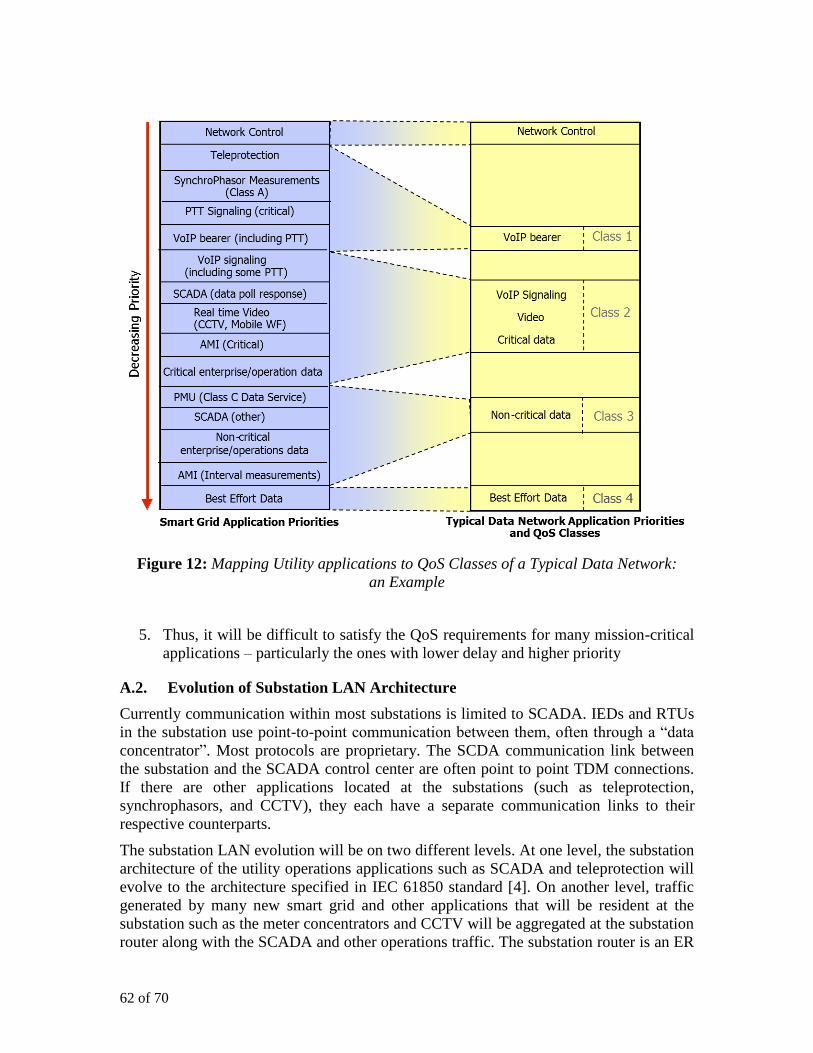
62 of 70
Figure 12: Mapping Utility applications to QoS Classes of a Typical Data Network:
an Example
5. Thus, it will be difficult to satisfy the QoS requirements for many mission-critical
applications – particularly the ones with lower delay and higher priority
A.2. Evolution of Substation LAN Architecture
Currently communication within most substations is limited to SCADA. IEDs and RTUs
in the substation use point-to-point communication between them, often through a “data
concentrator”. Most protocols are proprietary. The SCDA communication link between
the substation and the SCADA control center are often point to point TDM connections.
If there are other applications located at the substations (such as teleprotection,
synchrophasors, and CCTV), they each have a separate communication links to their
respective counterparts.
The substation LAN evolution will be on two different levels. At one level, the substation
architecture of the utility operations applications such as SCADA and teleprotection will
evolve to the architecture specified in IEC 61850 standard [4]. On another level, traffic
generated by many new smart grid and other applications that will be resident at the
substation such as the meter concentrators and CCTV will be aggregated at the substation
router along with the SCADA and other operations traffic. The substation router is an ER
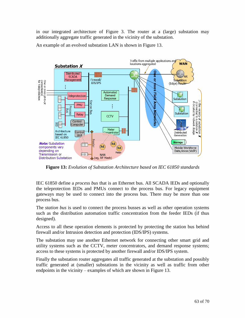
63 of 70
in our integrated architecture of Figure 3. The router at a (large) substation may
additionally aggregate traffic generated in the vicinity of the substation.
An example of an evolved substation LAN is shown in Figure 13.
Figure 13: Evolution of Substation Architecture based on IEC 61850 standards
IEC 61850 define a process bus that is an Ethernet bus. All SCADA IEDs and optionally
the teleprotection IEDs and PMUs connect to the process bus. For legacy equipment
gateways may be used to connect into the process bus. There may be more than one
process bus.
The station bus is used to connect the process busses as well as other operation systems
such as the distribution automation traffic concentration from the feeder IEDs (if thus
designed).
Access to all these operation elements is protected by protecting the station bus behind
firewall and/or Intrusion detection and protection (IDS/IPS) systems.
The substation may use another Ethernet network for connecting other smart grid and
utility systems such as the CCTV, meter concentrators, and demand response systems;
access to these systems is protected by another firewall and/or IDS/IPS system.
Finally the substation router aggregates all traffic generated at the substation and possibly
traffic generated at (smaller) substations in the vicinity as well as traffic from other
endpoints in the vicinity – examples of which are shown in Figure 13.

64 of 70
Note that the utility may continue to use its existing TDM networks and/or possibly
Ethernet connections for the teleprotection traffic. The teleprotection traffic may not be
carried over the IP network for a period of time.

65 of 70
Appendix B: Wireless Access
B1. LTE Architecture
The LTE architecture is streamlined to optimize network performance, maximize data
throughput, and minimize latency. Much simpler than earlier generations of mobile
systems, the LTE architecture will comprise of a simple configuration of just eNode B
and the combined Serving / PDN Gateway (SP-GW) and additionally one control plane
entity (MME). See Figure 14.
Figure 14: All IP LTE Architecture
This is Essentially a two-node architecture – the eNB acting as the base station
connecting to the users (such as utility endpoints) over an IP connection over the radio
access network (called eUTRAN for LTE) and the (combined) Serving and Packet Data
Network gateway (S/PGW) over IP backhaul. The LTE architecture also fully supports
usage of low-cost and secure backhauling such as carrier-grade Ethernet rather than
E1/T1 based leased lines thus leading to operations cost reduction The S/PGW helps
connect the endpoints to the IP Enhance Packet Core that can be considered a part of the
utility IP network if the LTE deployment is utility-owned or to the IP network of the LTE
service provider.
Aligning with the broad trend to converge all communications traffic towards IP, LTE
employs IP-centric communication equipment and VoIP throughout the core and radio
networks. This is the basis to integrate communication needs from a wide range of smart
grid use cases into a single IP based system, whether they be low latency m2m
communications with field devices, interactive multimedia services with repair teams in
the field or video streaming from video surveillance cameras.
66 of 70
As an example for innovative low latency machine to machine communications within
the capabilities of LTE consider protection-related signalling along medium voltage lines
connecting to the DG spread in rural areas. The required latencies of less than 50 ms
make LTE an interesting choice when fiber optic or other wireline connections are not
easily available at these remote locations.
LTE has sophisticated QoS mechanism as part of the standard which support traffic
priorities and allows controlling and guaranteeing delays. This is important when the
utility’s network carries traffic with distinguished latency and priority requirements. As
indicated in Table III, very low latencies are possible. Thus, except possibly for the
teleprotection applications, LTE can support latency requirements for all utility
applications including the smart grid applications. The delays can be controlled by
configuring QoS parameters for the radio bearer. This is in contrast to competing
technologies such as mesh based radio systems with dynamically changing topologies
and unpredictable impacts from interference. On the other hand, the fixed topology of the
LTE network together with the comprehensive LTE QoS provides the utility with robust
control of the communication related delays – supporting a wide range of future current
and future mission critical applications.
What is needed for reasons of flexibility and scalability is a radio technology which can
provide seamless coverage throughout the whole service area of the utility – with a
minimum number of radio sites and at low cost.
Studies have shown that for a variety of smart grid services LTE supports large cell sizes
in the order of up to ~32 km when used as dedicated system in frequency bands < 1 GHz.
For the higher frequency bands around 2.3 GHz, still be reasonably large ~12.5 km large
cells can be built. LTE cells in 700 MHz are ~10 times larger than in 2.4 GHz with
corresponding impacts on the number of sites and cost required for providing coverage.
If spectrum < 1 GHz is available to the utility, high power LTE operation will be
particularly more competitive than other radio systems deployed in the unlicensed 2.4
GHz ISM band (or above) such as the necessarily low power operation of dedicated mesh
networks. If LTE TDD is used around 2.3 GHz, it will still compare favourably with
unlicensed systems, due to the available relatively higher TX powers and interference
free operation
Despite many uncertainties to what the smart grid exactly is, one trend is very clear: the
intelligence and control will expand towards the edge of the power system. Automation
expands from primary substations towards MV transmission lines, secondary substations
and even to the end customer (AMI, DR) as well as the spread-out DG.
Finally, it is extremely important that security is provided for, among other things, denial
of service protection, intrusion detection and eventually providing non-repudiation with
trust-by-wire mechanisms (ie, NON-ambiguity and trustworthiness in the networks).
B2. Sharing of LTE Networking Resources
LTE supports wide range of network infrastructure sharing models. Thus a utility may
share LTE resources with, say public safety. Infrastructure elements that can be shared
include sites, towers, antennas, shelters, site support, and even transmission.

67 of 70
It is also possible to share the RAN between the utility and the other service such as
public safety. Such sharing of the RAN (called eUTRAN for LTE) is illustrated in Figure
15.
Figure 15: Network Sharing: Multi-operator Core Network
Finally, even the spectrum may be shared between utility and another service with these
two operators providing services to their individual customers. Some of the possible
spectrum sharing scenarios are illustrated in Figure 16.

68 of 70
Figure 16: LTE Spectrum Sharing Options

69 of 70
Acronyms
ADR Automated Demand Response
AMI Advanced Metering Infrastructure
AR Access Router
BB Broadband
BR Backbone Router
CCTV Closed Circuit Television
CDMA Code Division Multiple Access
CEN Comité Européen de Normalisation
(European Committee for
Standardization)
CENELEC Comité Européen de Normalisation
Électrotechnique (European
Committee for Electrotechnical
Standardization)
CIM Common Information Model
DG Distributed Generation
DL Downlink
DLR Dynamic Line Rating
DR Demand Response
EC European Commission
EHV Extra High Voltage
EMS Energy Management System
eNB enhanced Node B
EPS Evolved Packet Core
ER Edge Router
ETSI European Telecommunications
Standards Institute
EUTC European Utilities Telecom Council
eUTRAN Evolved Universal Terrestrial Radio
Access Network
EV Electric Vehicle
EV-DO Evolved – Data Optimized
FAN Field Area Network
FDD Frequency Division Duplex
GHz GigaHertz
GPRS General Packet Radio Service
GPS Global Positioning System
HAN Home Area Network
HFC Hybrid Fiber Cable
HSPA High Speed Packet Access
HSS Home Subscriber Server
Hz Hertz
HV High Voltage
ICT Information and Communication
Technology
ICT4SM-
ARTDG
ICT for Smart Distributed
Generation
IDS Intrusion Detection System
IPS Intrusion (Detection and) Protection
System
IED Intelligent Electronic Device
IEC International Electromechanical
Commission
IP Internet Protocol
ISO International Standards Organization
KM Key Message
LMR Land Mobile Radio
LTE Long Term Evolution
LV Low Voltage
Mbps Megabit per second
MBB Mobile Broadband
MDMS Meter Data Management System
MHz Megahertz
MIMO Multiple Input Multiple Output
MME Mobility Management Entity
MPLS Multi-Protocol Label Switching
ms millisecond
MV Medium Voltage
NAN Neighborhood Area Network
NB Narrowband
NIST National Institute of Standards and
Technology
OFDM Orthogonal Frequency Division
Multiplexing
OpTel Operations - Telecommunications
PLC power Line Communication
PMU Phasor Measurement Unit
PRIME PoweRline Intelligent Metering
Evolution)
PTT Push-to-Talk
QoS Quality of Service
RAN Radio Access Network
RFC Request for Comment
RTU Remote Terminal unit
SCADA Supervisory Control and data
Acquisition
SLA Service Level Agreement
SOA Service Oriented Architecture
S/P-GW Serving/(Packet Data Network)
Gateway
SSL Secure Sockets Layers
TD Time Division (Duplex)
TDD Time Division Duplex
TDM Time Division Multiplexing

70 of 70
TLS Transport Layer Security
UL uplink
UNB Ultra Narrowband
UTC Utilities Telecom council
VoIP Voice over IP
VPN Virtual Private Network
WAN Wide Area Network
WF Workforce
WP Work Package