wrs artificial lift system - irp-cdn.multiscreensite.com · c) hydraulic lift with 10k void test....
TRANSCRIPT

WRS Artificial Lift System
Designed to adapt to any type of Artificial Lift Suspension!
Patent Pending

Artificial Lift and Down hole gauge monitoring Is fast Becoming the go to in the oil production market.
The WRS Artificial Lift suspension system will allow you to utilize the same Feed thru Wellhead and hanger system for all types of Artificial Lift Types. It also work equally as well with gauge wires, Fiber optic, etc., without the need for any penetrators or spliced connections.

WRS Artificial lift hanger system ***Patent Pending*** This system was designed to aid in the installation of Multiple types of artificial lift systems without the need to change hangers or adapters. The system can handle ESP suspension without the need for wire splicing. Converts to Gas lift with the same equipment just change out inserts for different line pass thru styles. Convert to rod completion with same changes. Convert to Hydraulic with same changes. Convert to straight production with same changes. Will allow for the passage of gauge wires without the need to do any splicing or without any type of penetration device to get you thru the hanger. Utilizes seals and inserts to accommodate these changes. No need to re plumb after completion switch over. Concentric completion! Temporary Hang off capabilities! Permanent completion utilizing the same equipment! Easy handling and operation! Safe and tested to hold 5k working pressure. String weight is handled with the bottom plate allowing for maximum load capacity.
Interchangeable inserts
Various seal combinations

Dual Wire ports ESP completion
Any combination of ESP wire X capillary and gauge wire can be achieved with the system. Wire size and combinations can be addressed easily by changing out seals and inserts to fit the combination.

Dual wire ports Gas lift completion
Dual capillary and gauge wires can easily be achieved with this system.

ESP Completion When installing the ESP, the last thing you need is to worry about unnecessary splices of the wires controlling your production number cost. Not only will this system allow for concentric completion avoiding costly eccentric setup, It will totally eliminate the need to cut and splice lines and wires during installation. The Patent Pending Hanger system is designed to be used during the running ,with night time seal off capabilities, but it is also designed to be used at final completion.
ESP installation
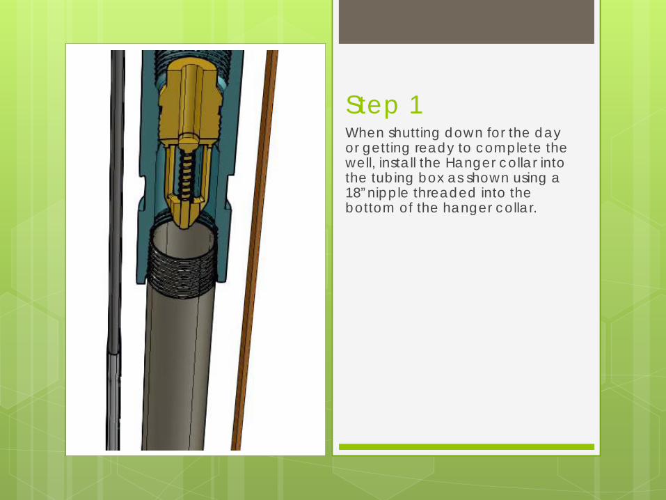
Step 1 When shutting down for the day or getting ready to complete the well, install the Hanger collar into the tubing box as shown using a 18”nipple threaded into the bottom of the hanger collar.

Step 2 Pull the hinge screw and open the Patent pending Split hanger and ready it to be installed around the grooved area of the collar.

Step 3 Install the Patent pending split wrap around in the slot in the collar to ensure positive up and down motion when raising and lowering the hanger into the well bore.

Step 4 Wrap around the collar . Pin to lock hanger in place. This places the hanger in that positive locked position to ensure up and down motion inside the BOP stack during installation and removal.

Step 5 Pull the pin to allow E line door to open. Strip back outer sheath from the E line to expose wires. (Caution should be taken not to damage the Lead Shield!!) Give yourself enough room to be able to separate the wires and insert them one at a time into the rubber of the hanger.

Step 6
a) Position the wires close to the hanger to begin inserting them into the rubber element. b) Starting from the back to the front. c) Lube the wires and slip them into position one at a time. d) Once there all in place ensure that the element has closed around each wire and is sitting firmly in place in its original form. (This also applies to gauge wires…fiber optic, electric, capillary, etc.…)

Step 7 Ensuring not to pinch the wires, close the door and pin with threaded shoulder bolt to encase the wires in the sealing pocket created inside the doors and seal element.

Step 8 Control line sealing. Pull the shoulder bolt to open the door. Lube the line and insert it into the seal element. Once in its position, inspect the element to ensure its back into position to allow for the door to be closed and pinned.

Step 9 Now that all the line have been inserted and secured in place. Finally inspection of the hanger should be done to insure that all the element splits are lined up with each opposing ends and that its ready to be lowered into the tubing head for the night.

Step 10 Lower it thru the stack and into the bowl . At this point the weight of the string will land on the bottom plate Lock down pins are now run in to contain the hanger in the bowl and seal off the well for the night by compressing down on the hanger and sealing off against the thru cables. ( E line, Control line, coupling, etc.)

Step 11 In a Temporary installation, When you return the next work day, its as easy as it was to un install as it was to install! Simply back off the lock down screws in the tubing head and lift the hanger out of the well. At this point, remove the pins holding the doors which are holding in the lines and remove the lines from the hanger. Re pin the doors. Pull the hanger pin and remove from the collar. Now, remove the collar nipple and collar from the string and save encase its needed again.
At this point, you should be ready to take off where you left off the day before. If for some reason you would need to hang off the tubing again, simple repeat steps 1-10 and the system will perform the same way. At the end of the setting process, you will need to finish your well and this same system is designed to be utilized for that also. Its recommended to use a new element, unless it is inspected by competent parties and deemed usable .

This will help to show the major difference of the to collar subs. The Rod completion sub has only a connection on each end with a straight thru bore ID. The Permanent has internal BPV threads with an external “S” seal groove at the top to complete inside the adapter and seal off. Both would be connected to an 18” pipe nipple for easy handling. The weight loading of the assembly is on the lower plate, allowing the upper plate to float and utilize the wellhead lockdown pins for sealing pressure .
Rod completion collar
Permanent collar

Multiple completion style adaptability
With interchangeable inserts and elements to match, the system can be utilized for a multitude of artificial lift types with only a small amount of expense.
Interchangeable inserts allow for different styles of completion
An assortment of elements allow for the different completion styles.

Completion
The system can be tailored to several types of completion scenarios. a)Free flow pressure completion. 10k working pressure. b) ESP completion with 5Kvoid test. c) Hydraulic lift with 10k void test. d)Gas lift with 10k void test. e) Rod lift with 10k void test. The system allows for miscellaneous sensor, electric, capillary and other types of penetrations thru the wellhead without the need for splicing.
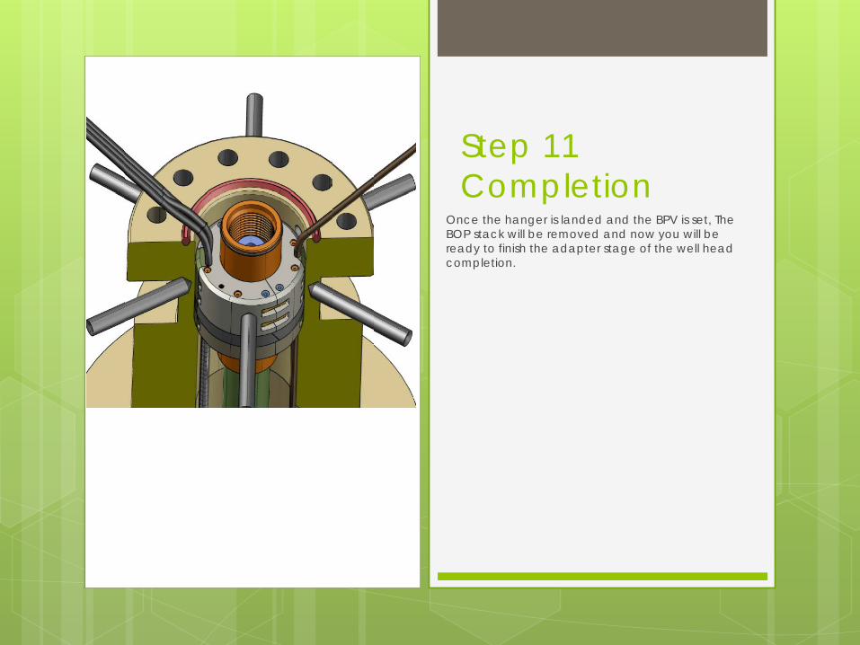
Step 11 Completion
Once the hanger is landed and the BPV is set, The BOP stack will be removed and now you will be ready to finish the adapter stage of the well head completion.

Step 12 Threading the e line and control line thru the ports in the adapter as it is lowered down over the hanger/bowl assembly is easy thru the larger ports. Take caution not to skin the wire or crimp the line as you come down.

Adapter Scenario's Because the hanger system has numerous types of combinations, we designed the system adapters to be able to handle all the different types of possibilities with minor parts to be changed. The exit cap and plug are the only items on the adapter that would need to be changed when switching between completion styles.

Step 12A As the adapter is lowered, pull outward on the lines to ensure the slack doesn’t kink on the bottom side!!

Step 12B With everything in place, continue to lower the adapter flange into place . The neck of the coupling with its “S” seal will seal off the upper portion of the cavity. The hanger seal seals off the annulus. The ring gasket seals off the outside at the top. The next step is to seal the penetrations at the wire and the control/injection line.

Step 13 Our Patent pending wire compression fitting will seal off the wire penetration in a very easily installed process as shown. 1) Insert split wedge around the wire. 2) Insert split washer. 3) Insert seal element. 4) Insert secondary washer. 5) Screw on compression cap. This locks the wire in place and seals it at the
same time.

Step 14 Sealing off the injection line is a simple process which involves and industry standard fitting which seals off the tubing with a swedgloc fitting. Should you be running this for gas lift, chances are we would furnish adapters and hangers with wire ports on each side to help to accommodate gauges and sensor cables along with capillary lines.

Final stage Installing the flow line.
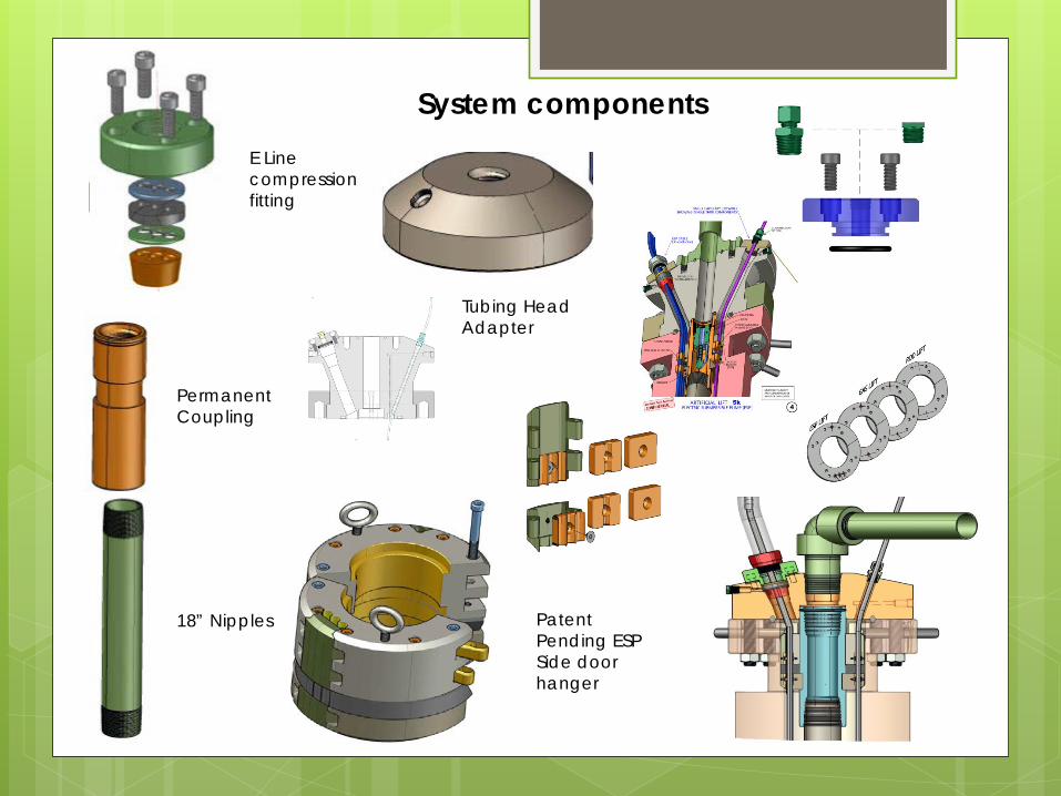
System components
Permanent Coupling
18” Nipples
E Line compression fitting
Tubing Head Adapter
Patent Pending ESP Side door hanger