wwt lesson 8 adec - acrp · · 2012-10-26the major components of a pumping system, ... •...
TRANSCRIPT
PUMP EQUIPMENTWHAT IS IN THIS SECTION?
1. The function of pumping systems
2. Common pump types
3. Basic theory of operation of centrifugal pumps
4. The basic theory of operation of diaphragm pumps
5. The major components of a pumping system, including the building and piping system
6. The terms used to identify common pumps and their components
7. The function of the major components of a centrifugal pump
8. The pumping process used by a pneumatic ejector
9. The components of an air lift pump
KEY WORDS
• Centrifugal force • Centrifugal pump
• Close-coupled pumps • Concentric reducer
• Displacement pumps • Dynamic pumps
• Energy • Eccentric reducer
• End suction centrifugal pumps • Frame-mounted pumps
• Impeller • Mechanical seal
• Packing • Seal water
• Shroud • Stuffing box
• Volute
Pumping Systems
- 307 -

PUMPING EQUIPMENTINTRODUCTIONSection Content & Purpose This section is intended to provide an overview of the
major pumping related components found in smallwastewater systems. The focus of the lesson will be onbasic theory, descriptions of components, commonnames of components and their general functions.
PUMP SYSTEM USESFunctions Wastewater pumping systems in small communities
are used to:• Pump wastewater through portions of the collection
system - a lift station• Pump wastewater from an individual house into a
pressure collection system• Pump wastewater effluent from the plant or septic
tank to a receiving body• Pump wastewater from a major collection point into
a treatment facility• Circulate glycol through a heat exchanger or heating
loop• Pump chemicals into the system
MAJOR COMPONENTSA pump station is composed of four sets of compo-nents:• The structure, including the wet well;• The hydraulic system; the pump and related piping.• The electrical system; the motor and its related com-
ponents.• The control system; pressure, flow and level switch-
es.STRUCTURE/BUILDINGSIntroduction In a wastewater system the most common pumping
structure is the lift station. This is typically a concreteor steel structure placed in the ground with a fiber-glass or wooden building placed over the wet well.Having a building over the wet well provides improvedaccess to the equipment during the months of badweather.
Basic Consideration Regardless of the design, most lift station buildingsare designed with the door opening out. This allowsaccess should there be a broken discharge line in thebuilding. The buildings should be vandal resistant,well heated in the winter and properly vented in thesummer.
Introduction to Small Wastewater Systems
- 308 -
HYDRAULIC SYSTEM
PUMP TYPES
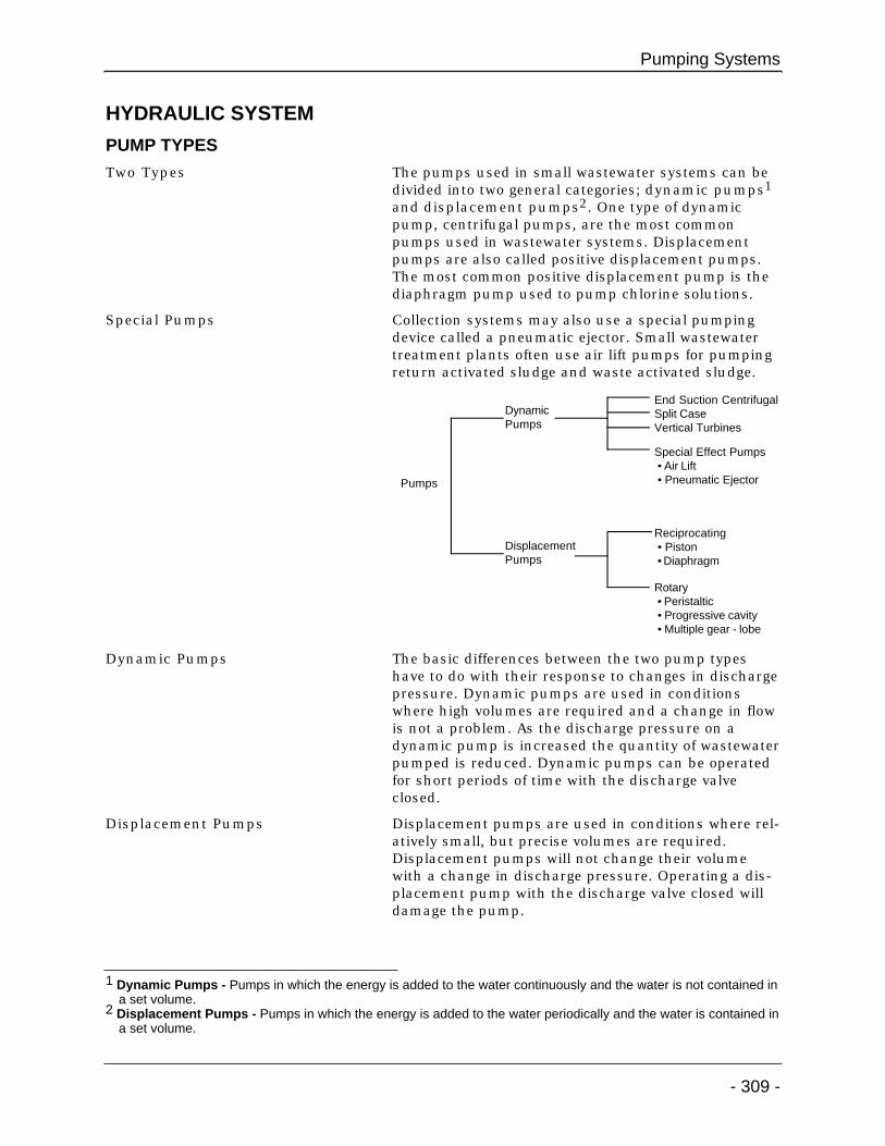
Two Types The pumps used in small wastewater systems can bedivided into two general categories; dynamic pumps1
and displacement pumps2. One type of dynamicpump, centrifugal pumps, are the most commonpumps used in wastewater systems. Displacementpumps are also called positive displacement pumps.The most common positive displacement pump is thediaphragm pump used to pump chlorine solutions.
Special Pumps Collection systems may also use a special pumpingdevice called a pneumatic ejector. Small wastewatertreatment plants often use air lift pumps for pumpingreturn activated sludge and waste activated sludge.
Dynamic Pumps The basic differences between the two pump typeshave to do with their response to changes in dischargepressure. Dynamic pumps are used in conditionswhere high volumes are required and a change in flowis not a problem. As the discharge pressure on adynamic pump is increased the quantity of wastewaterpumped is reduced. Dynamic pumps can be operatedfor short periods of time with the discharge valveclosed.
Displacement Pumps Displacement pumps are used in conditions where rel-atively small, but precise volumes are required.Displacement pumps will not change their volumewith a change in discharge pressure. Operating a dis-placement pump with the discharge valve closed willdamage the pump.
Pumping Systems
- 309 -
Pumps
DynamicPumps
DisplacementPumps
End Suction CentrifugalSplit CaseVertical Turbines
Special Effect Pumps • Air Lift • Pneumatic Ejector
Reciprocating • Piston • Diaphragm
Rotary • Peristaltic • Progressive cavity • Multiple gear - lobe
1 Dynamic Pumps - Pumps in which the energy is added to the water continuously and the water is not contained ina set volume.
2 Displacement Pumps - Pumps in which the energy is added to the water periodically and the water is contained ina set volume.

CENTRIFUGAL PUMP THEORY
Energy Input Device A pump is a device that puts energy3 into thewastewater. This energy can be expressed in twoways; an increase in pressure or an increase in flow.
Centrifugal Pumps - Energy Input If we cut a sectionout of the top of apipe and used acanoe paddle tomove the wastewa-ter we would have apump. It would notbe very efficient butwe would beinputting energyinto the wastewa-ter. If the paddlewere reshaped intoan impeller4 wewould be able toplace more energyinto the wastewa-ter. The energy istransferred fromthe impeller to the wastewater due to the frictionbetween the impeller and the wastewater. However,notice that a lot of the wastewater would splash outonto the floor. This is because centrifugal force5
causes the wastewater to fly outward away from theimpeller.
The Pump Case If we surround the impeller with a case we can controlthe wastewater and obtain a more efficient energytransfer. The case that is used is shaped like a spiraland is called a volute. Volute6 is a geometrical shape;like a circle,a square,etc. A snailshell isvoluteshaped. Theshape of thecase helpsus to deter-mine thedirection ofrotation ofthe pump.
Introduction to Small Wastewater Systems
- 310 -
3 Energy - The ability to do work. Energy can exist in one of several forms, such as heat, light, mechanical, electricalor chemical. Energy can neither be created nor destroyed, but can be transferred from one form to another.Energy also can exist in one of two states - either potential or kinetic.
4 Impeller - A rotating set of vanes designed to impart rotation to a mass of fluid.5 Centrifugal Force - The force that when a ball is whirled on a string, pulls the ball outward. On a centrifugal pump,
it is the force which throws water from the spinning impeller.6 Volute - The spiral shaped casing surrounding a pump impeller that collects the liquid discharged by the impeller.
IMPELLER
SHAFT
©AWWA
©AWWA
disc
harg
e
suction
IMPELLER EYE
IMPELLER
VOLUTE
POWER
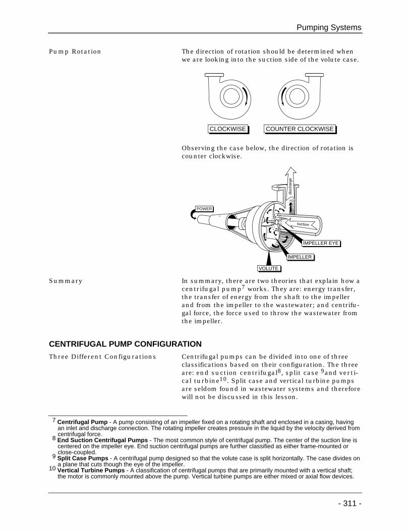
Pump Rotation The direction of rotation should be determined whenwe are looking into the suction side of the volute case.
Observing the case below, the direction of rotation iscounter clockwise.
Summary In summary, there are two theories that explain how acentrifugal pump7 works. They are: energy transfer,the transfer of energy from the shaft to the impellerand from the impeller to the wastewater; and centrifu-gal force, the force used to throw the wastewater fromthe impeller.
CENTRIFUGAL PUMP CONFIGURATION
Three Different Configurations Centrifugal pumps can be divided into one of threeclassifications based on their configuration. The threeare: end suction centrifugal8, split case 9and verti-cal turbine10. Split case and vertical turbine pumpsare seldom found in wastewater systems and thereforewill not be discussed in this lesson.
Pumping Systems
- 311 -
7 Centrifugal Pump - A pump consisting of an impeller fixed on a rotating shaft and enclosed in a casing, havingan inlet and discharge connection. The rotating impeller creates pressure in the liquid by the velocity derived fromcentrifugal force.
8 End Suction Centrifugal Pumps - The most common style of centrifugal pump. The center of the suction line iscentered on the impeller eye. End suction centrifugal pumps are further classified as either frame-mounted orclose-coupled.
9 Split Case Pumps - A centrifugal pump designed so that the volute case is split horizontally. The case divides ona plane that cuts though the eye of the impeller.
10 Vertical Turbine Pumps - A classification of centrifugal pumps that are primarily mounted with a vertical shaft;the motor is commonly mounted above the pump. Vertical turbine pumps are either mixed or axial flow devices.
CLOCKWISE COUNTER CLOCKWISE
disc
harg
e
suction
IMPELLER EYE
IMPELLER
VOLUTE
POWER
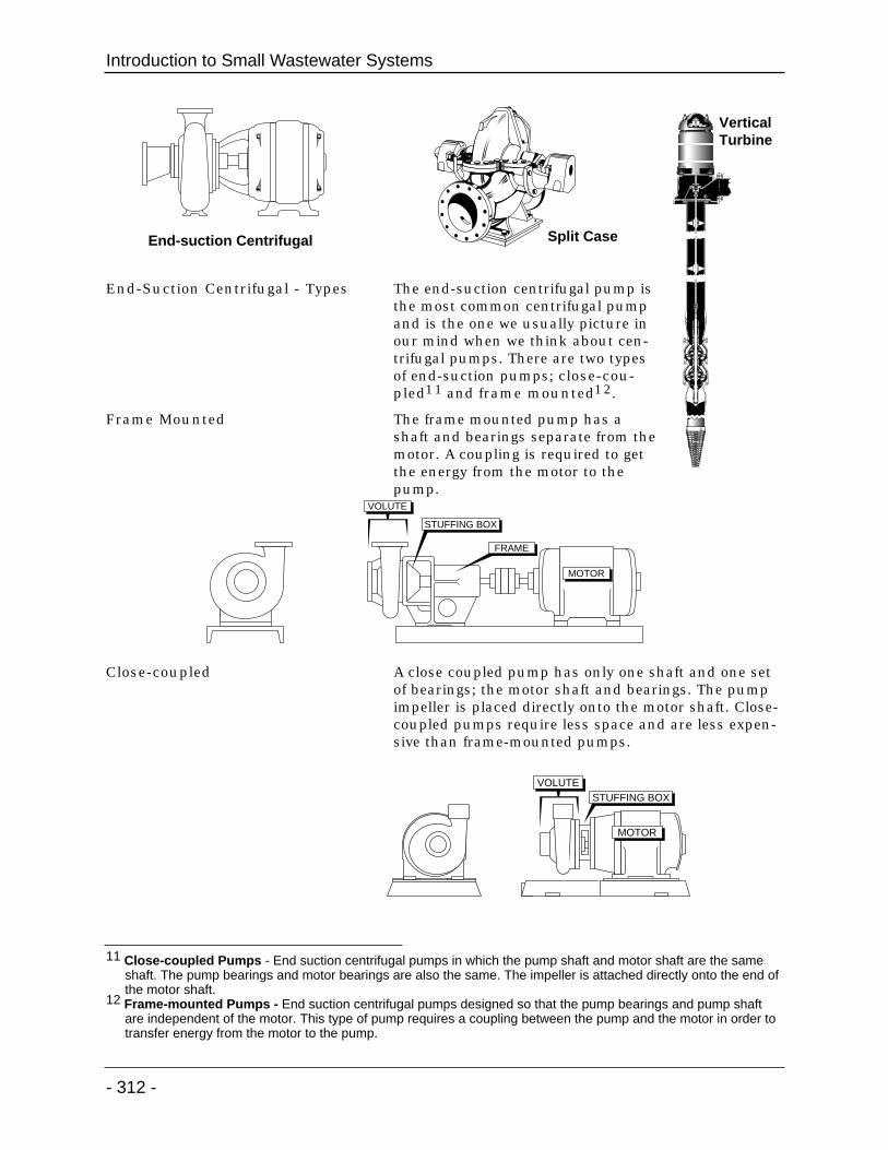
End-Suction Centrifugal - Types The end-suction centrifugal pump isthe most common centrifugal pumpand is the one we usually picture inour mind when we think about cen-trifugal pumps. There are two typesof end-suction pumps; close-cou-pled11 and frame mounted12.
Frame Mounted The frame mounted pump has ashaft and bearings separate from themotor. A coupling is required to getthe energy from the motor to thepump.
Close-coupled A close coupled pump has only one shaft and one setof bearings; the motor shaft and bearings. The pumpimpeller is placed directly onto the motor shaft. Close-coupled pumps require less space and are less expen-sive than frame-mounted pumps.
Introduction to Small Wastewater Systems
- 312 -
End-suction Centrifugal Split Case
VOLUTE
STUFFING BOX
MOTOR
FRAME
11 Close-coupled Pumps - End suction centrifugal pumps in which the pump shaft and motor shaft are the sameshaft. The pump bearings and motor bearings are also the same. The impeller is attached directly onto the end ofthe motor shaft.
12 Frame-mounted Pumps - End suction centrifugal pumps designed so that the pump bearings and pump shaftare independent of the motor. This type of pump requires a coupling between the pump and the motor in order totransfer energy from the motor to the pump.
VOLUTESTUFFING BOX
MOTOR
Vertical Turbine
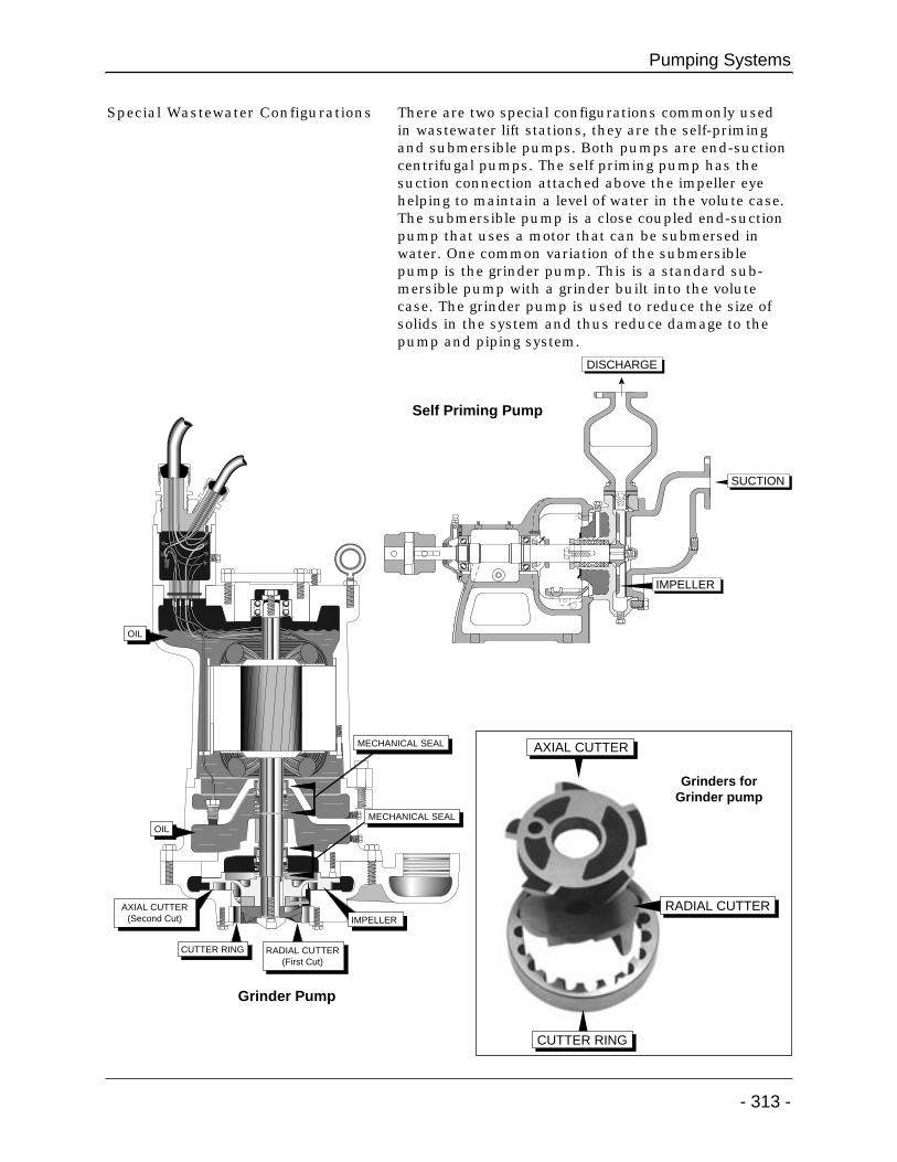
Special Wastewater Configurations There are two special configurations commonly usedin wastewater lift stations, they are the self-primingand submersible pumps. Both pumps are end-suctioncentrifugal pumps. The self priming pump has thesuction connection attached above the impeller eyehelping to maintain a level of water in the volute case.The submersible pump is a close coupled end-suctionpump that uses a motor that can be submersed inwater. One common variation of the submersiblepump is the grinder pump. This is a standard sub-mersible pump with a grinder built into the volutecase. The grinder pump is used to reduce the size ofsolids in the system and thus reduce damage to thepump and piping system.
Pumping Systems
- 313 -
CUTTER RING
IMPELLER
OIL
OIL
RADIAL CUTTER(First Cut)
AXIAL CUTTER(Second Cut)
MECHANICAL SEAL
MECHANICAL SEAL
RADIAL CUTTER
CUTTER RING
AXIAL CUTTER
DISCHARGE
IMPELLER
SUCTION
Grinder Pump
Self Priming Pump
Grinders forGrinder pump
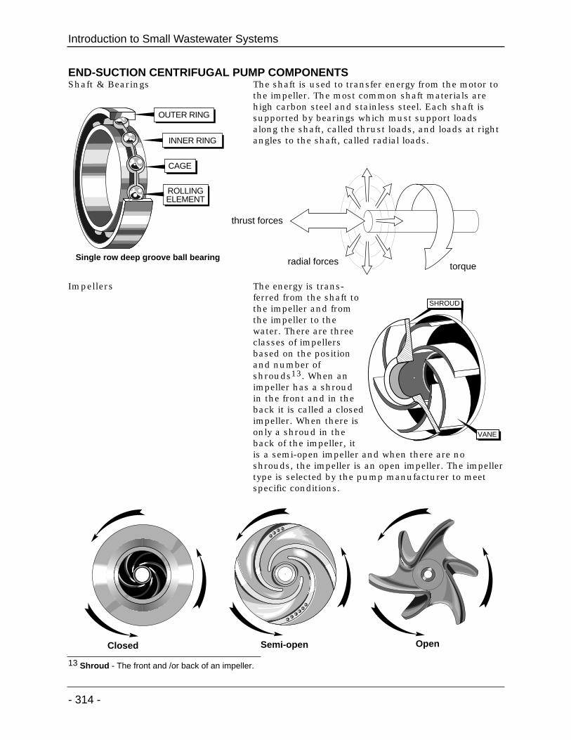
END-SUCTION CENTRIFUGAL PUMP COMPONENTSShaft & Bearings The shaft is used to transfer energy from the motor to
the impeller. The most common shaft materials arehigh carbon steel and stainless steel. Each shaft issupported by bearings which must support loadsalong the shaft, called thrust loads, and loads at rightangles to the shaft, called radial loads.
Impellers The energy is trans-ferred from the shaft tothe impeller and fromthe impeller to thewater. There are threeclasses of impellersbased on the positionand number ofshrouds13. When animpeller has a shroudin the front and in theback it is called a closedimpeller. When there isonly a shroud in theback of the impeller, itis a semi-open impeller and when there are noshrouds, the impeller is an open impeller. The impellertype is selected by the pump manufacturer to meetspecific conditions.
Introduction to Small Wastewater Systems
- 314 -
13 Shroud - The front and /or back of an impeller.
thrust forces
radial forces torque
ROLLINGELEMENT
OUTER RING
INNER RING
CAGE
Single row deep groove ball bearing
SHROUD
VANE
Closed Semi-open Open
Pumping Systems
- 315 -
22 21 19 20 17
15
31
2435
36
1614
13 18 28
1
27
4 5 2
3
23
30
24
3219
33 34
29
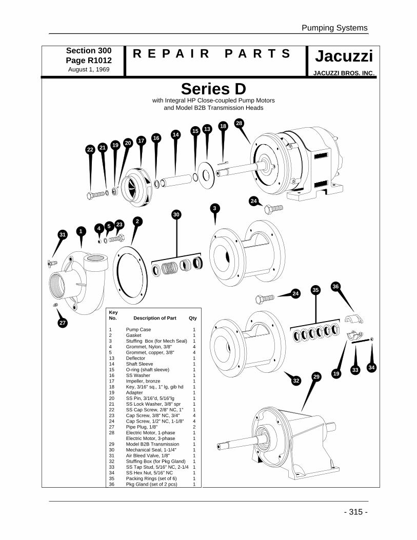
Section 300Page R1012August 1, 1969
R E P A I R P A R T S JacuzziJACUZZI BROS. INC.
Series Dwith Integral HP Close-coupled Pump Motors
and Model B2B Transmission Heads
KeyNo. Description of Part Qty
1 Pump Case 12 Gasket 13 Stuffing Box (for Mech Seal) 14 Grommet, Nylon, 3/8" 45 Grommet, copper, 3/8" 413 Deflector 114 Shaft Sleeve 115 O-ring (shaft sleeve) 116 SS Washer 117 Impeller, bronze 118 Key, 3/16" sq., 1" lg, gib hd 119 Adapter 120 SS Pin, 3/16"d, 5/16"lg 121 SS Lock Washer, 3/8" spr 122 SS Cap Screw, 2/8" NC, 1" 123 Cap Screw, 3/8" NC, 3/4" 424 Cap Screw, 1/2" NC, 1-1/8" 427 Pipe Plug, 1/8" 228 Electric Motor, 1-phase 1
Electric Motor, 3-phase 129 Model B2B Transmission 130 Mechanical Seal, 1-1/4" 131 Air Bleed Valve, 1/8" 132 Stuffing Box (for Pkg Gland) 133 SS Tap Stud, 5/16" NC, 2-1/4 134 SS Hex Nut, 5/16" NC 135 Packing Rings (set of 6) 136 Pkg Gland (set of 2 pcs) 1

Wear Rings With closedimpellers theimpeller fits veryclose to the case. Asa result, the case isworn by materialpassing from thehigh pressure sideof the impeller tothe low pressureside. To protect thecase brass or stain-less steel wear ringsare inserted into the case.
Introduction to Small Wastewater Systems
- 316 -
PACKING
IMPELLER
VOLUTE
SHAFT
PACKING GLAND
WEAR RING
WearRings
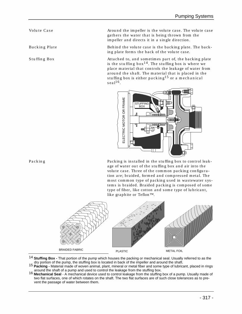
Volute Case Around the impeller is the volute case. The volute casegathers the water that is being thrown from theimpeller and directs it in a single direction.
Backing Plate Behind the volute case is the backing plate. The back-ing plate forms the back of the volute case.
Stuffing Box Attached to, and sometimes part of, the backing plateis the stuffing box14. The stuffing box is where weplace material that controls the leakage of water fromaround the shaft. The material that is placed in thestuffing box is either packing15 or a mechanicalseal16.
Packing Packing is installed in the stuffing box to control leak-age of water out of the stuffing box and air into thevolute case. Three of the common packing configura-tion are; braided, formed and compressed metal. Themost common type of packing used in wastewater sys-tems is braided. Braided packing is composed of sometype of fiber, like cotton and some type of lubricant,like graphite or Teflon™.
Pumping Systems
- 317 -
BRAIDED FABRIC PLASTIC METAL FOIL
ELE
CT
RIC
MO
TO
R O
R F
RA
ME
STUFFINGBOX
14 Stuffing Box - That portion of the pump which houses the packing or mechanical seal. Usually referred to as thedry portion of the pump, the stuffing box is located in back of the impeller and around the shaft.
15 Packing - Material made of woven animal, plant, mineral or metal fiber and some type of lubricant, placed in ringsaround the shaft of a pump and used to control the leakage from the stuffing box.
16 Mechanical Seal - A mechanical device used to control leakage from the stuffing box of a pump. Usually made oftwo flat surfaces, one of which rotates on the shaft. The two flat surfaces are of such close tolerances as to pre-vent the passage of water between them.

Mechanical Seals Mechanical seals are installed in the stuffing box forthe same purpose as packing, to control leakagethrough the stuffing box. A mechanical seal is com-posed of two sets of components, primary componentsand secondary components. The primary componentsare made up of two pieces, a rotating component anda stationary component. One of these must be made ofa hard material (usually ceramic) and one of a softmaterial (usually carbon). One component must bestationary and the other must rotate on the shaft. Thetolerance between these two faces prevents water frompassing. The secondary portion of the mechanical sealis composed of secondary seals that prevent waterfrom leaking along the shaft, a spring or set of springsthat provide pressure on the faces and some type ofretainer used to hold the rotating element on theshaft.
Packing Gland/Seal Gland In order to controlleakage with packing,pressure must beplaced on the pack-ing. This pressure isapplied by the pack-ing gland, two piecesof metal at the back ofthe stuffing box.When a pump uses amechanical seal thiscomponent is called aseal gland.
Introduction to Small Wastewater Systems
- 318 -
Impe
ller
SpringSeal Gland
Rotating Element
Secondary Seals
RetainerStationary Element
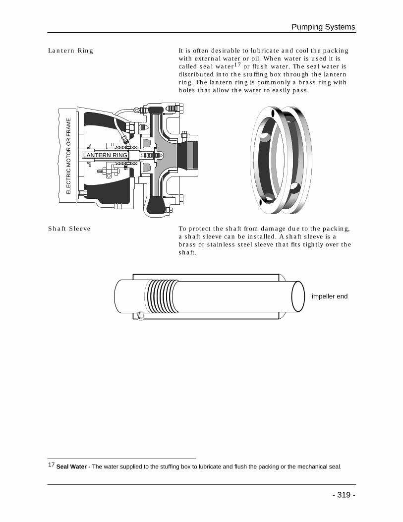
Lantern Ring It is often desirable to lubricate and cool the packingwith external water or oil. When water is used it iscalled seal water17 or flush water. The seal water isdistributed into the stuffing box through the lanternring. The lantern ring is commonly a brass ring withholes that allow the water to easily pass.
Shaft Sleeve To protect the shaft from damage due to the packing,a shaft sleeve can be installed. A shaft sleeve is abrass or stainless steel sleeve that fits tightly over theshaft.
Pumping Systems
- 319 -
ELE
CT
RIC
MO
TO
R O
R F
RA
ME
LANTERN RING
impeller end
17 Seal Water - The water supplied to the stuffing box to lubricate and flush the packing or the mechanical seal.

END-SUCTION CENTRIFUGAL PUMP - PIPING SYSTEM
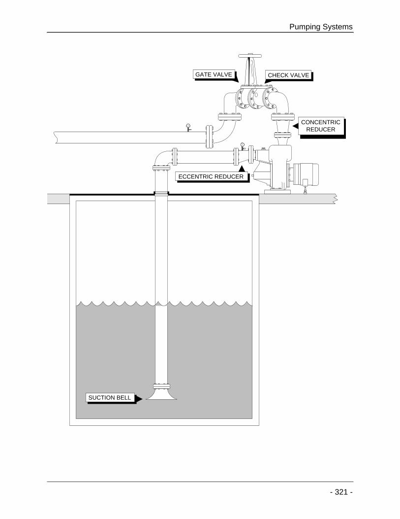
Suction Piping The suction piping more than any other external fac-tor can impact pump performance. In order to reducethe impact of the piping system the suction piping isusually designed one pipe size larger than the inlet ofthe pump, with smooth piping material and fittings.Isolation valves on the suction side of a pump shouldonly be knife gate or plug valves. As the piping reach-es the pump it is reduced to meet the pump connec-tion using an eccentric reducer18. The eccentricreducer prevents air accumulation in the piping.
Discharge Piping The discharge side of a pump usually starts with aconcentric reducer19 taking the pipe up to one pipesize larger than the pump discharge. An isolationvalve, preferably a knife gate or plug valve, is normallyinstalled on the discharge. To reduce repair cost aflange by flange spool or expansion joint is placedbetween the isolation valve and the pump.
Check Valve To prevent the flow of water back through the pump acheck valve is often placed in the discharge line. Thecheck valve could be a swing check or ball check.
Gauges In order to evaluate pump operating conditions, pres-sure gauges are placed on the suction and dischargesides of a pump. Ball valves are installed at the baseof the gauges to allow easy replacement and to shutthe gauges off when not in use, extending their life.
Seal Water Seal water is used to cool packing and prevent materi-al from entering the stuffing box from the volute case.When the pump utilizes a mechanical seal rather thanpacking, the seal water is used to lubricate the facesof the seal. Seal water is supplied from the dischargeof the volute case or an external source. A pressuregauge should be installed in the seal water line inorder to assure that flow of seal water is into the stuff-ing box. If the seal water source is the drinking watersystem then an air gap must be placed between thedrinking water system and the wastewater pump. Thisair gap prevents contamination of the drinking watersystem as a result of backflow from the wastewaterpump.
More Information Additional information on the piping system found ina typical lift station can be found in the lesson on col-lection systems.
Introduction to Small Wastewater Systems
- 320 -
18 Eccentric Reducer - A device used to connect a large pipe to a smaller pipe so that one edge of both pipes isaligned.
19 Concentric Reducer - A device used to connect a large pipe to a smaller pipe so that the center lines of bothpipes are aligned.
Pumping Systems
- 321 -
ECCENTRIC REDUCER
CONCENTRICREDUCER
GATE VALVE CHECK VALVE
SUCTION BELL
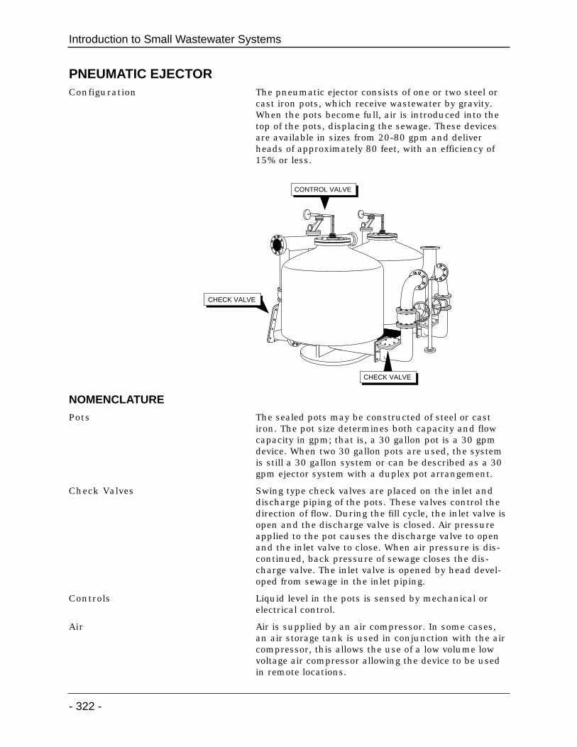
PNEUMATIC EJECTORConfiguration The pneumatic ejector consists of one or two steel or
cast iron pots, which receive wastewater by gravity.When the pots become full, air is introduced into thetop of the pots, displacing the sewage. These devicesare available in sizes from 20-80 gpm and deliverheads of approximately 80 feet, with an efficiency of15% or less.
NOMENCLATURE
Pots The sealed pots may be constructed of steel or castiron. The pot size determines both capacity and flowcapacity in gpm; that is, a 30 gallon pot is a 30 gpmdevice. When two 30 gallon pots are used, the systemis still a 30 gallon system or can be described as a 30gpm ejector system with a duplex pot arrangement.
Check Valves Swing type check valves are placed on the inlet anddischarge piping of the pots. These valves control thedirection of flow. During the fill cycle, the inlet valve isopen and the discharge valve is closed. Air pressureapplied to the pot causes the discharge valve to openand the inlet valve to close. When air pressure is dis-continued, back pressure of sewage closes the dis-charge valve. The inlet valve is opened by head devel-oped from sewage in the inlet piping.
Controls Liquid level in the pots is sensed by mechanical orelectrical control.
Air Air is supplied by an air compressor. In some cases,an air storage tank is used in conjunction with the aircompressor, this allows the use of a low volume lowvoltage air compressor allowing the device to be usedin remote locations.
Introduction to Small Wastewater Systems
- 322 -
CONTROL VALVE
CHECK VALVE
CHECK VALVE

OPERATION SEQUENCE
Three Steps The operation of the ejector is relatively simple andinvolves three basic steps–filling, filled and discharge.
Filling During the filling stage, the discharge check valve isheld closed by a downstream head above the valve.The inlet valve is forced open by incoming sewage. Airin the pot is vented to the upstream manhole throughthe air inlet line.
Full When the tank becomes full, the air control valveshuts off the vent line and allows air into the pot.
Discharging As the air pressure in the pot increases, the inletcheck valve is closed and the sewage is forced out pastthe discharge valve.
Pumping Systems
- 323 -
INLETCHECKVALVE
OUTLETCHECKVALVE

AIR LIFT PUMPSConfiguration The air lift pump is relatively simple, consisting of a
large pipe extending into a fluid and an air supply thatintroduces air into the pipe below the water level.This air supply pipe may extend down inside or out-side the pump pipe.
Use Air lift pumps are used as the return and waste sludgepump on many small activated sludge treatmentplants.
COMPONENTS
The main components of an air lift pump include anair supply, air inlet line and control valve. The air inletline is connected to a footpiece. Below the footpiece isthe fluid inlet pipe called the tailpipe. Above the foot-piece is the eductor pipe and outlet piping.
THEORY OF OPERATION
Drop in Specific Gravity As air is introduced into water inside the pump, thespecific gravity of the wastewater inside is reducedbelow that of the wastewater outside the pump. Thisdifference in specific gravity causes the wastewater onthe outside of the pump to rush into the pipe, thuspushing the wastewater in the pipe up and out.
Velocity Carries Solids As the wastewater approaches the entrance of thepump, its velocity carries large amounts of solidsthrough the pump.
Introduction to Small Wastewater Systems
- 324 -
OUTLET
EDUCTOR PIPE
AIR
TAILPIPE
FOOTPIECE
INLET
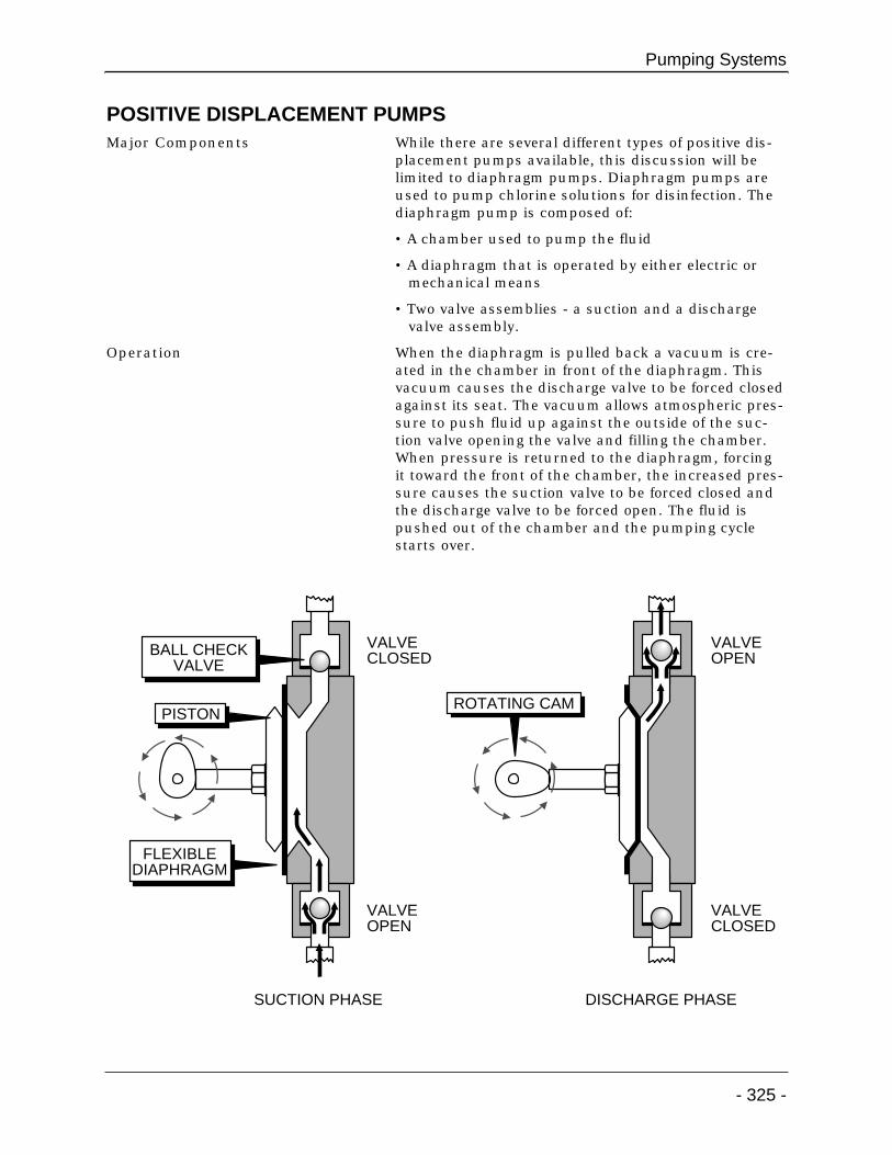
POSITIVE DISPLACEMENT PUMPSMajor Components While there are several different types of positive dis-
placement pumps available, this discussion will belimited to diaphragm pumps. Diaphragm pumps areused to pump chlorine solutions for disinfection. Thediaphragm pump is composed of:
• A chamber used to pump the fluid
• A diaphragm that is operated by either electric ormechanical means
• Two valve assemblies - a suction and a dischargevalve assembly.
Operation When the diaphragm is pulled back a vacuum is cre-ated in the chamber in front of the diaphragm. Thisvacuum causes the discharge valve to be forced closedagainst its seat. The vacuum allows atmospheric pres-sure to push fluid up against the outside of the suc-tion valve opening the valve and filling the chamber.When pressure is returned to the diaphragm, forcingit toward the front of the chamber, the increased pres-sure causes the suction valve to be forced closed andthe discharge valve to be forced open. The fluid ispushed out of the chamber and the pumping cyclestarts over.
Pumping Systems
- 325 -
VALVEOPEN
VALVECLOSED
VALVECLOSED
VALVEOPEN
FLEXIBLEDIAPHRAGM
PISTON
BALL CHECKVALVE
ROTATING CAM
SUCTION PHASE DISCHARGE PHASE
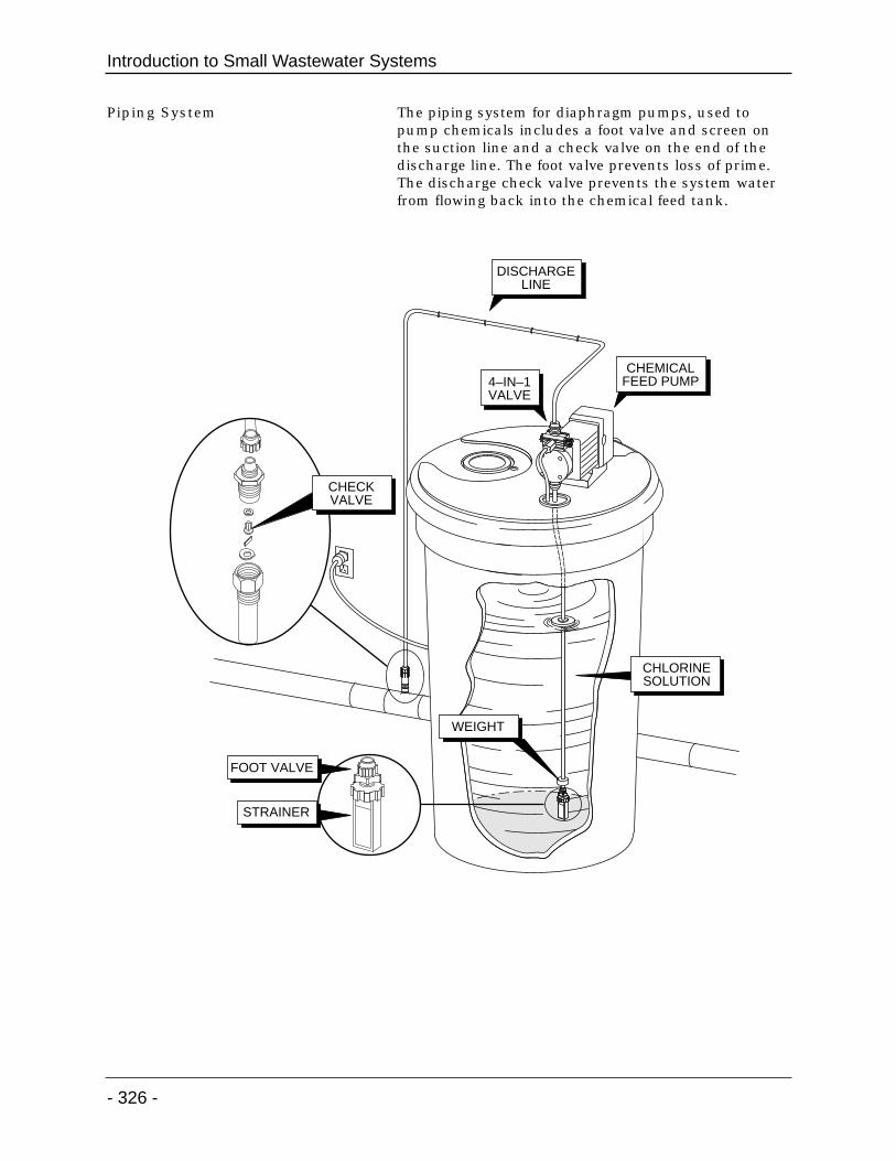
Piping System The piping system for diaphragm pumps, used topump chemicals includes a foot valve and screen onthe suction line and a check valve on the end of thedischarge line. The foot valve prevents loss of prime.The discharge check valve prevents the system waterfrom flowing back into the chemical feed tank.
Introduction to Small Wastewater Systems
- 326 -
CHEMICALFEED PUMP4–IN–1
VALVE
DISCHARGELINE
WEIGHT
CHLORINESOLUTION
CHECKVALVE
FOOT VALVE
STRAINER
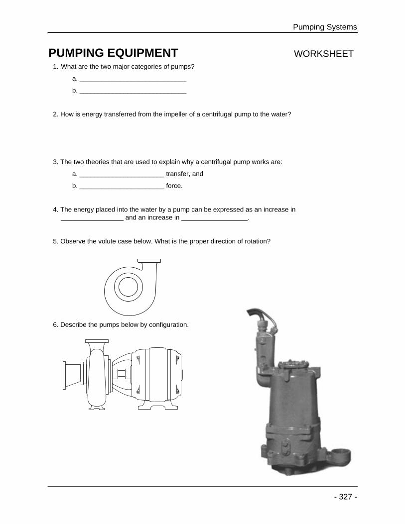
PUMPING EQUIPMENT WORKSHEET1. What are the two major categories of pumps?
a. _____________________________
b. _____________________________
2. How is energy transferred from the impeller of a centrifugal pump to the water?
3. The two theories that are used to explain why a centrifugal pump works are:
a. _______________________ transfer, and
b. _______________________ force.
4. The energy placed into the water by a pump can be expressed as an increase in_________________ and an increase in __________________.
5. Observe the volute case below. What is the proper direction of rotation?
6. Describe the pumps below by configuration.
Pumping Systems
- 327 -

7. Identify the components indicated in the drawing below. Compare the numbers on the drawing to thelist provided.
______ a. Volute case
______ b. Mechanical seal
______ c. Impeller
______ d. Stuffing Box
_____ e. Shaft sleeve
8. What is the energy source used to operate a pneumatic ejector?
9. Pumps are rated in _____________ per __________________.
10. There are two items in a centrifugal pump that are designed to wear out and at the same time protecta portion of the pump. They are:
a. The _______________________ ________________ - designed to protect the shaft.
b. The _______________________ ________________ - designed to protect the volute.
Introduction to Small Wastewater Systems
- 328 -
22 21 19 20 17
15
31
1614 13
18 28
1
27
4 5 2
3
23
30
24

11. Identify the components indicated in the drawing below. Compare the numbers on the drawing to thelist provided.
______ a. Pumps suction valve
______ b. Pumps discharge valve
______ c. Diaphragm
______ d. Foot valve
______ e. Injection check valve
12. Identify the components in the drawing below. Compare the letters on the drawing to the list provided.
______ a. Boot or secondary seal
______ b. Spring
______ c. Stationary component
______ d. Carbon face - rotating component
Pumping Systems
- 329 -
4
2
3
1
5
A B C D E
13. _______________ water is used to cool the packing and provide lubrication to the mechanical seal.
14. Packing and mechanical seals serve the same purpose, __________________ leakage through thestuffing box.
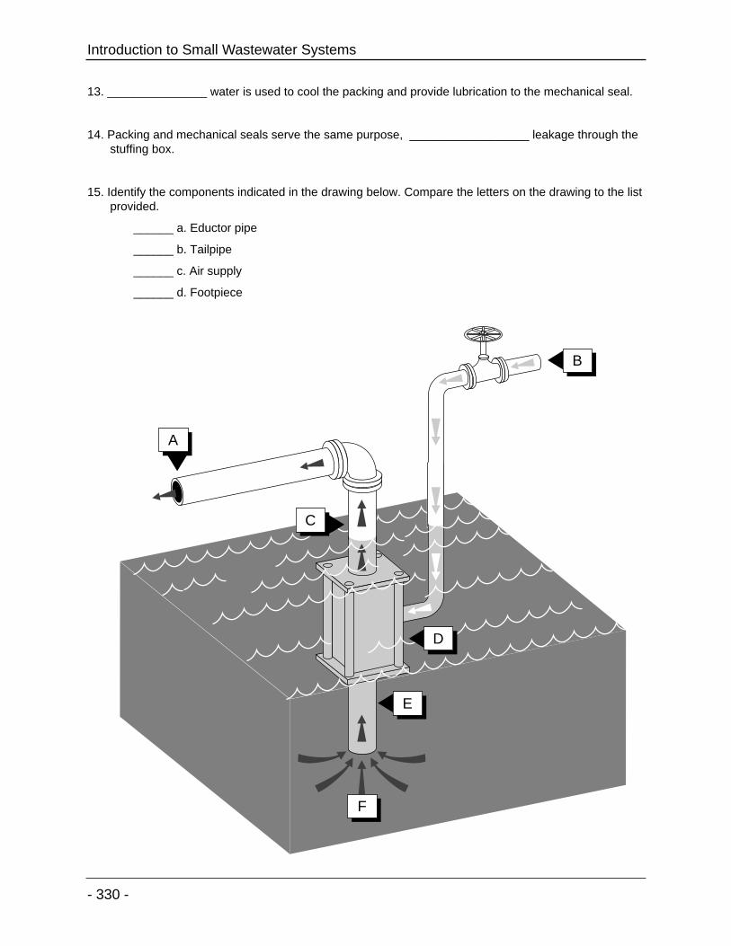
15. Identify the components indicated in the drawing below. Compare the letters on the drawing to the listprovided.
______ a. Eductor pipe
______ b. Tailpipe
______ c. Air supply
______ d. Footpiece
Introduction to Small Wastewater Systems
- 330 -
A
F
B
C
E
D