x a real-time multi-channel memory controller and optimal ...kgoossens/2014-tecs-mc.pdf · x a...
TRANSCRIPT

X
A Real-Time Multi-Channel Memory Controller andOptimal Mapping of Memory Clients to Memory Channels
MANIL DEV GOMONY, Eindhoven University of Technology, The Netherlands
BENNY AKESSON, Czech Technical University in Prague, Czech Republic
KEES GOOSSENS, Eindhoven University of Technology, The Netherlands
Ever increasing demands for main memory bandwidth and memory speed/power trade-off led to the in-troduction of memories with multiple memory channels, such as Wide IO DRAM. Efficient utilization of amulti-channel memory as a shared resource in multi-processor real-time systems depends on mapping ofthe memory clients to the memory channels according to their requirements on latency, bandwidth, commu-nication and memory capacity. However, there is currently no real-time memory controller for multi-channelmemories, and there is no methodology to optimally configure multi-channel memories in real-time systems.As a first work towards this direction, we present two main contributions in this article: 1) A configurablereal-time multi-channel memory controller architecture with a novel method for logical-to-physical addresstranslation. 2) Two design-time methods to map memory clients to the memory channels, one an optimalalgorithm based on an integer programming formulation of the mapping problem, and the other a fastheuristic algorithm. We demonstrate the real-time guarantees on bandwidth and latency provided by ourmulti-channel memory controller architecture by experimental evaluation. Furthermore, we compare theperformance of the mapping problem formulation in a solver and the heuristic algorithm against two exist-ing mapping algorithms in terms of computation time and mapping success ratio. We show that an optimalsolution can be found in 2 hours using the solver and in less than 1 second with less than 7%mapping failureusing the heuristic for realistically sized problems. Finally, we demonstrate configuring a Wide IO DRAM ina High-Definition (HD) video and graphics processing system to emphasize the practical applicability andeffectiveness of this work.
Categories and Subject Descriptors: C.3 [Computer Systems Organization]: Special-Purpose andApplication-Based Systems — Real-Time and Embedded Systems
General Terms: Algorithms, Design, Performance
Additional Key Words and Phrases: Multi-channel memories, Memory controller, Optimal mapping, Heuris-tic algorithm
ACM Reference Format:
Gomony, M.D., Akesson, B., and Goossens, K., 2014. A Real-Time Multi-Channel Memory Controller andOptimal Mapping of Memory Clients to Memory Channels. ACM Trans. Embedd. Comput. Syst. X, X, Arti-cle X (January 2014), 25 pages.DOI:http://dx.doi.org/10.1145/0000000.0000000
1. INTRODUCTION
In heterogeneous multi-processor platforms, main memory (off-chip DRAM) is typi-cally a shared resource for cost reasons and to enable communication between the
This work was partially funded by projects EU FP7 288008 T-CREST and 288248 Flextiles, CA505BENEFIC, CA703 OpenES, ARTEMIS-2013-1 621429 EMC2, 621353 DEWI, and by the European socialfund within the framework of realizing the project ”Support of inter-sectoral mobility and quality enhance-ment of research teams at Czech Technical University in Prague”, CZ.1.07/2.3.00/30.0034.Corresponding authors address: Gomony, M.D., Faculty of Electrical Engineering, Eindhoven University ofTechnology; email: [email protected] to make digital or hard copies of part or all of this work for personal or classroom use is grantedwithout fee provided that copies are not made or distributed for profit or commercial advantage and thatcopies show this notice on the first page or initial screen of a display along with the full citation. Copyrightsfor components of this work owned by others than ACM must be honored. Abstracting with credit is per-mitted. To copy otherwise, to republish, to post on servers, to redistribute to lists, or to use any componentof this work in other works requires prior specific permission and/or a fee. Permissions may be requestedfrom Publications Dept., ACM, Inc., 2 Penn Plaza, Suite 701, New York, NY 10121-0701 USA, fax +1 (212)869-0481, or [email protected]© 2014 ACM 1539-9087/2014/01-ARTX $15.00DOI:http://dx.doi.org/10.1145/0000000.0000000
ACM Transactions on Embedded Computing Systems, Vol. X, No. X, Article X, Publication date: January 2014.

X:2 M.D.Gomony et al.
processing elements. Such platforms run several applications with firm and soft real-time requirements [Kollig et al. 2009; van Berkel 2009; Melpignano et al. 2012], andmoreover, the firm real-time applications impose strict worst-case requirements onmain memory performance in terms of bandwidth and/or latency [van der Wolf andGeuzebroek 2011; Steffens et al. 2008]. These requirements must be guaranteed atdesign time to reduce the verification effort, which is made possible using real-timememory controllers [Paolieri et al. 2013; Akesson and Goossens 2011a; Reineke et al.2011; Shah et al. 2012; Bayliss and Constantinides 2012; Wu et al. 2013; Li et al.2014; Kim et al. 2014] that bound the memory access time by employing predictablearbiters, such as Time Division Multiplexing (TDM) and Round-Robin. Moreover, real-time memory controllers can be analyzed using shared resource abstractions, such asthe Latency-Rate (LR) server model [Stiliadis and Varma 1998] which can be used informal performance analysis based on e.g., network calculus [Cruz 1991] or data-flowanalysis [Sriram and Bhattacharyya 2000].Memories with multiple physical channels and wide interfaces, such as Wide IO
DRAMs [JEDEC ], are essential to meet the main memory power/bandwidth demandsof future real-time systems [Gomony et al. 2012]. In multi-channel memories, a mem-ory client can be mapped to multiple memory channels by interleaving its memory re-quests across different memory channels after splitting it into smaller sized requests.Previous studies on multi-channel memories show that mapping soft real-time mem-ory clients to multiple memory channels according to their memory request sizes ben-efit average-case performance [Sancho et al. 2010; Cabarcas et al. 2010; Nikara et al.2009]. In addition to request sizes, firm real-time memory clients in real-time multi-processor platforms come with different requirements on memory bandwidth, latency,communication and memory capacity as well. The bandwidth allocated to firm real-time memory clients must be minimized to maximize the slack bandwidth that canbe allocated to the soft and non real-time clients in the system, which improves theiraverage-case performance [Lin and Brandt 2005]. The optimal mapping of the memoryclients to the memory channels for efficient memory bandwidth utilization results indifferent granularities at which the memory requests from each of the clients are inter-leaved in each channel, which requires a configurablememory controller and logical-to-physical address translation logic. Currently, there is no configurable real-time mem-ory controller architecture for multi-channel memories and there is no methodologyto map firm real-time memory clients to memory channels, meeting their bandwidth,latency, communication and memory capacity requirements.This article presents two of our main contributions: 1) A real-time multi-channel
memory controller architecture, with a new programmable Multi-Channel Interleaverand a novel method for logical-to-physical address translation that enables interleav-ing of a memory request in different sizes across any number of memory channels.2) Two design-time methods to determine the optimal mapping of memory clientsto the memory channels considering their requirements on bandwidth, latency, com-munication and memory capacity. The first method is an optimal algorithm basedon an integer programming formulation of the mapping problem, and the second afast heuristic algorithm. We demonstrate by experimentation that our multi-channelmemory controller satisfies the real-time requirements of the memory clients. Further-more, we experimentally compare the computation time and mapping success ratio ofthe optimization problem formulation in a solver and the heuristic algorithm againsttwo existing mapping algorithms. Finally, we demonstrate configuring a multi-channelWide IO DRAM for a High-Definition (HD) video and graphics processing system usingour approach.In the remainder of this article, Section 2 reviews the related work, Section 3 gives
an introduction to state-of-the-art real-time memory controllers and the LR servermodel. In Section 4, we introduce our proposed multi-channel memory controller ar-chitecture, including our method for logical-to-physical address translation. The two
ACM Transactions on Embedded Computing Systems, Vol. X, No. X, Article X, Publication date: January 2014.

A Real-Time Multi-Channel Memory Controller and Optimal Mapping of Memory Clients to Memory ChannelsX:3
proposed methods to map memory clients to memory channels, the one based on in-teger programming formulation and the heuristic algorithm are presented in Sec-tion 5 & 6, respectively. In Section 7, we present both the experimental evaluationof the multi-channel memory controller architecture and the performance evaluationof our two mapping methods. Section 8 then presents a case study of configuring aWide IO DRAM in an HD video and graphics processing system, and finally we con-clude in Section 9.
2. RELATED WORK
Among the previous related work, some exploit the benefits of interleaving data acrossmultiple memory channels. [Aho et al. 2009; Nikara et al. 2009; Zhu et al. 2002; Cabar-cas et al. 2010] proposed interleaving data across the memory channels such that allchannels are accessed by a single transaction to improve average-case performance.Similarly, [Casini 2008] proposed splitting the traffic within a logical address regionacross multiple memory channels to improve average-case performance by reducingaverage latency. Dynamic mechanisms for efficient data placement to reduce averagememory access latency in a system comprising multiple memory controllers is pro-posed by [Awasthi et al. 2010]. However, all of them focus on the improvement ofaverage-case performance, and do not consider providing guarantees on bandwidthand latency to firm real-time applications.The rest of the related work focus on memory controller architectures and logical-
to-physical address translation for multi-channel memories. [Zhang et al. 2010] pro-posed a parallel-access mechanism in which two separate DDR Finite State Machines(FSM) are used to control eight memory channels of a 3D-DRAM. The proposed ar-chitecture by [Loi and Benini 2010] has every processing element allocated to itsown local DRAM channel with a memory controller, and a custom crossbar is usedto route incoming traffic from other processing elements. The multi-channel NANDflash memory controller by [Ou et al. 2011] uses a dynamic mapping strategy by usinga mapping table that stores the logical-to-physical address translation, and a crossbarswitch for routing traffic across multiple memory channels. Also, the multi-channelmemory controller architecture by [Bouquet 2000] routes an incoming request to anyof the memory channels using a crossbar. [Zhang et al. 2012] presented an architec-ture for fine-grained DRAM access of memory chips in a DIMM by grouping them inlogical sub-ranks of different interface widths and accessing them concurrently. How-ever, neither of the aforementioned memory controller architectures provide any firmperformance guarantees and hence they cannot be used for formal verification of firmreal-time clients. Conversely, even though there are real-time memory controllers thatprovide bounds on memory performance [Paolieri et al. 2013; Akesson and Goossens2011a; Reineke et al. 2011; Shah et al. 2012; Bayliss and Constantinides 2012; Wuet al. 2013; Li et al. 2014; Kim et al. 2014], they do not consider multi-channel memo-ries and interleaving memory requests across multiple memory channels, i.e., they donot support an efficient mapping of memory clients to memory channels, which couldlead to larger design costs.In our previous work [Gomony et al. 2013], we presented a high-level architecture
of a real-time multi-channel memory controller and an optimal method for mappingmemory clients to memory channels based on an integer programming formulation ofthe mapping problem. As an extension of our previous work, in this article, we presentthe detailed architecture of the multi-channel memory controller including its exper-imental evaluation using a SystemC prototype implementation. We extend our opti-mization problem formulation to determine an optimal frame size for a TDM arbiter.In addition, we present a fast heuristic algorithm to map memory clients to the chan-nels including its performance comparison with the optimal method and two existingmapping algorithms.
ACM Transactions on Embedded Computing Systems, Vol. X, No. X, Article X, Publication date: January 2014.

X:4 M.D.Gomony et al.
3. BACKGROUND
This work relies on existing single-channel real-time memory controllers to boundthe execution time of a memory transaction, and uses the LR server model as theshared resource abstraction to derive bounds on service provided by predictable ar-biters. Hence, we introduce them in this section.
3.1. Real-time memory controllers
State-of-the-art real-time memory controllers [Paolieri et al. 2013; Akesson andGoossens 2011a; Reineke et al. 2011; Shah et al. 2012; Bayliss and Constantinides2012; Wu et al. 2013; Li et al. 2014; Kim et al. 2014] bound the execution time of amemory transaction by fixing the memory access parameters of a transaction, suchas burst length and number of read/write commands, at design time. These parame-ters define the access granularity of the memory controller, which defines the amountof data read/written from/to the memory per request. For a fixed access granularity,real-time memory controllers use a fixed memory command schedule according to thecommand timing requirements provided by the memory data-sheet, which bounds theworst-case execution time of a read/write transaction. Also, the worst-case bandwidthoffered by a memory for a fixed access granularity can be computed [Akesson andGoossens 2011b]. In this article, we refer to a memory transaction of a fixed size asa service unit, and the time taken to serve such a service unit is a service cycle. Theservice cycle for a read and a write transaction can be different and depends on thememory device and the memory controller.
3.2. LR servers
Latency-Rate (LR) servers [Stiliadis and Varma 1998] is a general model to capturethe worst-case behavior of various scheduling algorithms or arbiters in a simple uni-fied manner, which helps to formally verify the service provided by a shared resource.There are many arbiters belonging to the class of LR servers, such as TDM, Round-Robin and its variants Weighted Round-Robin (WRR) [Katevenis et al. 1991], DeficitRound-Robin (DRR) [Shreedhar and Varghese 1996], and priority-based arbiters witha rate-regulator, such as Credit-Controlled Static Priority (CCSP) [Akesson et al. 2008]and Priority Based Scheduler (PBS) [Steine et al. 2009]. The LR abstraction enablesmodeling of many different arbiters, and is compatible with a variety of formal analysisframeworks, such as data-flow analysis [Sriram and Bhattacharyya 2000] or networkcalculus [Cruz 1991].
..N/ρ'..
~N~
Accumulated
service untis
Service cycles
Requested service
Provided service
Minimum provided service
ρ'
~Ɵ~
Fig. 1. Example service curves of a LR server showing service latency (Θ) and completion latency (N/ρ′).
Using the LR abstraction, a lower linear bound on the service provided by an arbiterto a client or requestor can be derived. In this article, we use the term requestor todenote a memory client that requests access to a memory resource with certain band-width and latency requirements. Figure 1 shows example service curves of a LR server.
ACM Transactions on Embedded Computing Systems, Vol. X, No. X, Article X, Publication date: January 2014.

A Real-Time Multi-Channel Memory Controller and Optimal Mapping of Memory Clients to Memory ChannelsX:5
The requested service by a requestor at a time consists of one or more service units,indicated on the y-axis of the figure. The minimum service provided to the requestoris the service guaranteed by the LR abstraction, which depends on two parameters,namely the service latency Θ and the allocated rate ρ′ (bandwidth). The service latencyis intuitively the maximum time before the allocated rate is provided, as seen in thefigure, and depends on the choice of arbiter and its configuration, e.g. allocated rateand/or priority [Akesson and Goossens 2011b]. After a request consisting of N serviceunits is scheduled to be served, it receives service at the allocated rate ρ′ and it hencetakes N/ρ′ service cycles to finish serving the request, called the completion latency of
the requestor. The worst-case latency L (in service cycles) of a requestor is the totaltime taken by its request of size N service units at the head of its request queue to getserved in the worst-case 1, which is the sum of the service latency and the completionlatency, given by Equation (1). The advantage of this approach is that it can be appliedto other arbiters belonging to the class of LR servers by changing the expression for Θ.
L = Θ+ ⌈N/ρ′⌉ (1)
This work considers a TDM arbiter with continuous slot allocation as an exampleof a LR server, but our approach generally applies to other LR servers with linearexpression for Θ, such as a TDM arbiter with distributed slot allocation. As mentionedbefore, the service cycle duration for a read and write can be different. Since a re-questor can issue a read or write request in a TDM slot, we consider a slot size equalto the maximum of read or write service cycles. Note that it is shown in [Goossens et al.2013] that the service cycle for read and write transactions can be made equally longwith negligible loss in the guaranteed memory bandwidth. Figures 2(a) & 2(b) show aTDM frame of size f with requestor R allocated to two slots using continuous and dis-tributed slot allocation strategies, respectively. Here, R gets a rate ρ′ = 2/6, since twoout of six slots are allocated to R. The service latency (Θ) of R is 4 and 2 for continuousand distributed TDM, respectively, because of the interference from other requestorsthat occupy the remaining set of TDM slots. In terms of rate ρ′ and/or frame size f , theservice latencies of continuous and distributed TDM are given by Θ = f × (1 − ρ′) andΘ = f/(f × ρ′)− 1, respectively, as shown in [Akesson and Goossens 2011b].
f
ρ' = 2/6x x x x R R
Ɵ
f
Ɵ
x x R x x R
(a) (b)
Fig. 2. Example TDM frame of size f showing service latency (Θ) of requestor R with its slots allocatedusing (a) continuous and (b) distributed allocation strategies.
Hence, for a TDM arbiter with a frame size f , the worst-case latency of a requestorwith an allocated rate of ρ′ for continuous and distributed TDM is given by Equa-tions (2) & (3), respectively, in which both service latency and completion latency arerounded up to make the bound conservative.
L = ⌈f × (1− ρ′)⌉+ ⌈N/ρ′⌉ (2)
L = f/⌈f × ρ′⌉ − 1 + ⌈N/ρ′⌉ (3)
1For simplicity, we do not consider requestors with multiple outstanding requests, although it can be addedif the characterizations of the arriving traffic is taken into consideration to bound the waiting time in thequeue [Stiliadis and Varma 1998].
ACM Transactions on Embedded Computing Systems, Vol. X, No. X, Article X, Publication date: January 2014.

X:6 M.D.Gomony et al.
4. MULTI-CHANNEL MEMORY CONTROLLER FOR REAL-TIME SYSTEMS
In this section, we present our proposed real-time multi-channel memory controller ar-chitecture. We start this section with an analysis of the impact of interleaving memoryrequests across multiple memory channels on the guaranteed service provided by ar-biters belonging to the class of LR servers, which we refer to as LR arbiters. Then, wepresent our proposed architecture of multi-channel memory controller which is basedon the conclusions from the analysis, followed by a novel method for logical-to-physicaladdress translation.
4.1. Multi-channel memories and LR servers
Compared to a single-channel memory, multi-channel memories give us the opportu-nity to interleave memory requests at different granularities across the memory chan-nels. When the memory request of a requestor is interleaved across multiple memorychannels with each channel consisting of an LR arbiter, the worst-case latency is themaximum of the worst-case latencies among all the memory channels to which the re-quest is interleaved. Using the LR model, the worst-case latency of a requestor with arequired rate (bandwidth) ρ′ increases when the number of channels to which its re-quest is interleaved increases. This counter-intuitive result is shown in Equation (4),which shows the worst-case latency for a TDM arbiter in each memory channel, as-suming the required rate ρ′ and the total number of service units N in a memoryrequest are distributed evenly across the number of channels to which the request isinterleaved, nCh. It can be seen that the service latency increases with nCh, however,the completion latency remains constant 2. However, note that the worst-case latencycan be reduced by interleaving a memory request across multiple memory channelsand by allocating a higher rate than requested, i.e., over-allocating rate.
L′ =
⌈
f ×(
1− ρ′
nCh
)
⌉
+
⌈
N/nCh
ρ′/nCh
⌉
=
⌈
f ×(
1− ρ′
nCh
)
⌉
+
⌈
N
ρ′
⌉
(4)
Interleaving a memory request to more than one memory channel is unavoidableunder the following four conditions: (1) When the latency requirement of a requestorcannot be met in a single channel even after allocating a 100% bandwidth (ρ′ = 1) tothe requestor. This could happen with larger request sizes as can be seen in Equa-tion (2), if the request size is large such that even after allocating a 100% bandwidth(ρ′ = 1) of a channel, it does not meet its latency requirement, it must be interleavedacross multiple channels with an over-allocated rate. (2) When the bandwidth require-ment of a requestor could not be satisfied with the available bandwidth in a singlememory channel. (3) When the memory capacity requirements cannot be met with thecapacity available in a memory channel. (4) When a requestor needs to communicatewith another requestor whose requests are interleaved across multiple memory chan-nels for any of the previous three reasons, since communicating requestors must bemapped to the same channels.In a real-time system consisting of several memory requestors with different request
sizes and diverse requirements on bandwidth, latency, communication and memory ca-pacity, the optimal mapping of requestors to the memory channels for minimal band-width utilization results in different degrees of interleaving across the memory chan-nels for each requestor. This implies that the existing methods, in which all requestorsare interleaved in the same fashion to the memory channels are not always optimal.Hence, we need a programmable memory controller architecture that can be config-
2This conclusion is valid for all other LR arbiters as well since they all have the rate term, ρ′, which willalways gets split across channels and the completion latency remains constant. This is evident from theirworst-case latency equations [Akesson and Goossens 2011b].
ACM Transactions on Embedded Computing Systems, Vol. X, No. X, Article X, Publication date: January 2014.

A Real-Time Multi-Channel Memory Controller and Optimal Mapping of Memory Clients to Memory ChannelsX:7
ured to interleave memory requests of a requestor to any number of available memorychannels at different granularities.
4.2. Real-time multi-channel memory controller architecture
To enable mapping of memory requests from memory clients to memory channels atdifferent granularities, our multi-channel memory controller performs Channel Inter-leaving, by which an incoming memory request is split into several service units ofequal size and routes them to different memory channels. The proposed multi-channelmemory controller, shown in Figure 3, consists of a Multi-Channel Interleaver, and aChannel Controller in each memory channel. The Channel Controller can be any state-of-the-art real-time memory controller [Paolieri et al. 2013; Akesson and Goossens2011a; Reineke et al. 2011; Shah et al. 2012; Bayliss and Constantinides 2012; Wuet al. 2013; Li et al. 2014; Kim et al. 2014] employing any LR arbiter. We use a Multi-Stage Crossbar that connects each requestor to every Channel Controller. The Multi-Channel Interleaver consists of an Atomizer, Channel Selector (CS) and a SequenceGenerator connected to each memory requestor. The Multi-Channel Interleaver hasseparate request and response paths for each requestor.
Channel
Controller 2
Channel
Controller 1Multi-Channel Interleaver
Memory
Channel 1
Memory
Channel 2
Arbiter 1
Arbiter 2
Sequence Gen 1
Sequence Gen 2
Sequence Gen 3
Atomizer 1
Atomizer 2
Atomizer 3
CS1
CS2
CS3
1
2
1
3
5
Multi-stage
Crossbar
Memory
Client 3
Memory
Client 2
Memory
Client 1
3
4
5
66
4
2
Fig. 3. High-level view of real-time multi-channel memory controller architecture showing three memoryclients and two memory channels. The Atomizer splits a memory request in to smaller service units andthe Channel Selector (CS) routes these service units to the different memory channels according to theconfiguration in the Sequence Generators.
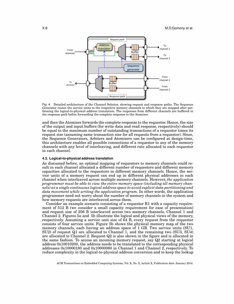
A detailed architecture of the Channel Selector showing both request and responsepaths is shown in Figure 4. In the request path, the Atomizer first splits an incomingmemory request into a number of service units, and then the Sequence Generatorroutes them to the respective memory channels. The Sequence Generator performslogical-to-physical address translation (explained in the next section) for each of theservice units before routing them to the memory channels. The buffers at each outputof the Channel Selector ensures non-blocking delivery of service units (write data) tothe differentmemory channels (assuming no input buffers in the Channel Controllers).The service units routed to the different memory channels may get served at differenttime instants, and hence the (read) responses from the memory channels may arriveat different times and even out-of-order. Hence, the incoming responses are buffered inthe response path until all of the responses from the different channels have arrived,
ACM Transactions on Embedded Computing Systems, Vol. X, No. X, Article X, Publication date: January 2014.
X:8 M.D.Gomony et al.
Address
translator
Sequence
generator
Buffer
Request path
Response path
addr
data
From
atomizer
To
atomizer
To
channel 1
From
channel 1
To
channel 2
From
channel 2
Buffer
Fig. 4. Detailed architecture of the Channel Selector, showing request and response paths. The SequenceGenerator routes the service units to the respective memory channels to which they are mapped after per-forming the logical-to-physical address translation. The responses from different channels are buffered inthe response path before forwarding the complete response to the Atomizer.
and then the Atomizer forwards the complete response to the requestor. Hence, the sizeof the output and input buffers (for write data and read response, respectively) shouldbe equal to the maximum number of outstanding transactions of a requestor times itsrequest size (assuming same transaction size for all requests from a requestor). Since,the Sequence Generators, Arbiters and Atomizers can be configured at design-time,this architecture enables all possible connections of a requestor to any of the memorychannels with any level of interleaving, and different rate allocated to each requestorin each channel.
4.3. Logical-to-physical address translation
As discussed before, an optimal mapping of requestors to memory channels could re-sult in each channel allocated a different number of requestors and different memorycapacities allocated to the requestors in different memory channels. Hence, the ser-vice units of a memory request can end up in different physical addresses in eachchannel when interleaved across multiple memory channels. However, the applicationprogrammer must be able to view the entire memory space (including all memory chan-nels) as a single continuous logical address space to avoid explicit data partitioning anddata movement while writing the application program. In other words, the applicationprogrammer need not worry about the number of memory channels in the system andhow memory requests are interleaved across them.Consider an example scenario consisting of a requestor R1 with a capacity require-
ment of 512 B (we consider a small capacity requirement for ease of presentation)and request size of 256 B interleaved across two memory channels, Channel 1 andChannel 2. Figures 5a and 5b illustrate the logical and physical views of the memory,respectively. Assuming a service unit size of 64 B, every request from the requestorconsists of four service units. Figure 5b shows the physical memory map of the twomemory channels, each having an address space of 1 GB. Two service units (SU1,SU2) of request Q1 are allocated to Channel 1, and the remaining two (SU3, SU4)are allocated to Channel 2. Request Q2 is also shown in the figure and is allocated inthe same fashion. To access an incoming memory request, say Q2 starting at logicaladdress 0x10010200, the address needs to be translated to the corresponding physicaladdresses 0x10000180 and 0x10000080 in Channel 1 and Channel 2, respectively. Toreduce complexity in the logical-to-physical address conversion and to keep the lookup
ACM Transactions on Embedded Computing Systems, Vol. X, No. X, Article X, Publication date: January 2014.

A Real-Time Multi-Channel Memory Controller and Optimal Mapping of Memory Clients to Memory ChannelsX:9
table size to a minimum, we propose a method to compute the logical address in eachchannel, expressed by Equation (5). Note that Request size is in service units.
0x10000000
SU4
SU3
SU2
SU1
SU8
SU7
SU6
SU5
SU6
SU5
SU2
SU1
SU8
SU7
SU4
SU3
0x10000000
0x10010100
0x10010200
0x1FFFFFFE
Requestor R1
0x10000000
0x10000100
0x10000180
0x17FFFFFF
0x10000080
0x17FFFFFF
Q1
(a) Logical view (b) Physical view
Q1
BaseAddrApp
BaseAddrCh2
BaseAddrCh1
Q2
Q2
Q1
Q2
Used region
Channel 1
Used region
Unused region
Unused region
Unused region
Channel 2
Fig. 5. Example memory map showing requestor R1 allocated to two memory channels, with every requestQ1 and Q2 interleaved across the two memory channels.
ReqAddrCh = (ReqAddrApp −BaseAddrApp)≫ log2(Request size/NChn) +BaseAddrChn
(5)The logical address offset between the requested logical address, ReqAddrApp, and
the logical base address of the application, BaseAddrApp, is computed first, and thenadded to the physical base address of the application in the corresponding channel,BaseAddrChn
. When a request is interleaved across multiple channels, the logical ad-dress offset is divided by the ratio of service units allocated to each memory channel.This is because the memory capacity allocated to a requestor in each channel is pro-portional to the number of service units of its request allocated to the channel. For afast and simple hardware implementation, division is performed using a logical shiftoperation. We hence require the number of service units allocated to each channel andrequest sizes (in service units) to be power of two 3.The logical base address of an application, BaseAddrApp, is generated by the appli-
cation compiler/linker, while the number of service units allocated to each channel,NChn
, is decided by the one of our two mapping methods, presented in Section 5 & 6.We generate the base addresses for all the requestors mapped to each of the channels,BaseAddrCh, based on the memory capacity allocated to them.Given that we have presented the multi-channel memory controller architecture
that can be programmed with any mapping, we proceed with our two methods to mapmemory clients to the memory channels in the next two sections.
5. OPTIMAL METHOD FOR MAPPING MEMORY REQUESTORS TO MEMORY CHANNELS
This section presents an optimal method for mapping memory clients to memory chan-nels based on an integer programming formulation of the mapping problem. First, wepresent a formal definition of our system and then a generic optimization problemformulation, which applies to any arbiter belonging to the class of LR servers.
5.1. System model
The set of memory channels is defined as c ∈ C, with each channel having a totalmemory capacity (in Bytes) given by Bch(c). The access granularity (in Bytes) of each
3The request sizes of most of the real-world memory requestors, such as CPUs, DSPs, LCD & DMA con-trollers are in the order of power of two [Steffens et al. 2008; Texas Instruments Inc. ].
ACM Transactions on Embedded Computing Systems, Vol. X, No. X, Article X, Publication date: January 2014.

X:10 M.D.Gomony et al.
memory channel is given by AG, with a service cycle (in ns) given by SCns 4. For eachmemory channel c ∈ C, the worst-case bandwidth (in MB/s) can be computed for a fixedaccess granularity AG (e.g. see [Akesson and Goossens 2011b]), and is given by bch(c).Consider a set of requestors denoted by r ∈ R, each with a worst-case latency re-
quirement (in ns) given by Lns(r), minimum bandwidth requirement (in MB/s) givenby b(r), and a total memory capacity requirement (in Bytes) given by B(r). Note thatthe minimum rate required by a requestor can be computed as the ratio of its mini-mum bandwidth requirement b(r) and the worst-case bandwidth of a channel bch(c).The worst-case latency of a requestor (in service cycles) in each channel c ∈ C is givenby Lc(r), and is defined as:
∀r ∈ R : Lc(r) = ⌊Lns(r)/SCns(c)⌋ (6)
The request size (in Bytes) of requests from a requestor r ∈ R is given by s(r). Weassume a constant request size for all requests from a single requestor since it typi-cally holds for the real-time requestors under consideration, such as CPUs, hardwareaccelerators, DMA and LCD controllers. The number of service units in each requestis given by q(r) and is defined by Equation (7). Since the request sizes, s(r), and accessgranularity of a memory device,AG, is in the order of power of two, q(r) will be a powerof two.
∀r ∈ R : q(r) = s(r)/AG (7)
Each requestor r ∈ R has an associated group number given by g(r), which rep-resents the communication dependency with other requestors, or in other words, re-questors that need to communicate through shared memory are assigned the samegroup number. In the next section, we define the optimization problem statement andformulate it as an integer programming problem. A summary of the memory systemand requestor parameters and their corresponding notations are given in Table I & II,respectively.
Table I. Memory system parameters
Parameter name NotationSet of memory channels C
Memory capacity (in Bytes)of each memory channel
Bch(c)
Access granularity (in Bytes)of each memory channel
AG
Service cycle duration (in ns) SCns
Worst-case bandwidth (inMB/s) of each memorychannel
bch(c)
Table II. Requestor parameters
Parameter name NotationSet of requestors RWorst-case latency requirement (in ns) Lns(r)Minimum bandwidth requirement (in MB/s) b(r)Total memory capacity requirement (in Bytes) B(r)
Worst-case latency (in service cycles) in eachchannel
Lc(r)
Request size (in Bytes) s(r)Request size (in service units) q(r)Group number g(r)
5.2. Optimization problem formulation
In this section, we present the formulation of the mapping problem as an integer pro-gramming problem. As mentioned before, we need to minimize the bandwidth allo-cated to firm real-time requestors to maximize the slack bandwidth, which improvesthe average-case performance of soft real-time requestors in the system. Hence, we de-fine our optimization problem as follows: Find the mapping of requestors to the memorychannels, the number of service units allocated to those channels,Nc, and a rate, ρ′c, foreach requestor r ∈ R in each memory channel c ∈ C, such that all requestor require-ments are satisfied and the sum of rates allocated to all requestors is minimized. Theoptimization problem is defined as:
4For simplicity, we assume the same access granularity in all memory channels.
ACM Transactions on Embedded Computing Systems, Vol. X, No. X, Article X, Publication date: January 2014.

A Real-Time Multi-Channel Memory Controller and Optimal Mapping of Memory Clients to Memory ChannelsX:11
Minimize:∑
c∈C
∑
r∈R
ρ′c(r) (8)
Such that the following seven constraints are satisfied:
Constraint 1: The worst-case latency of each requestor r ∈ R after allocation L′(r)
must be less than or equal to its worst-case latency requirement L(r), and is defined as:
∀r ∈ R : L′(r) ≤ L(r) (9)
The service units of every request of a requestor are allocated across the memorychannels such that each requestor has a (Θ, ρ′) pair per channel. The worst-case la-
tency of a requestor r ∈ R in each channel c ∈ C is then given by Lc′(r), and is defined
by Equation (10) 5, where Θc(r) is the service latency of a requestor in each channel.
∀c ∈ C, r ∈ R : Lc′(r) = Θc(r) + ⌈Nc(r)/ρ
′c(r)⌉ (10)
The worst-case latency of a requestor r ∈ R is then the maximum of the worst-caselatencies among all the memory channels, which is defined as:
∀c ∈ C, r ∈ R : L′(r) = maxc∈C
Lc′(r) (11)
Themax function is removed to enable formulation as an integer programming prob-lem, and Constraint 1 is then defined as:
∀c ∈ C, r ∈ R : L(r) − Lc′(r) ≥ 0 (12)
Constraint 2: The sum of rates allocated to all requestors in each memory channelc ∈ C must not be greater than 1, i.e., 100%, defined as:
∀c ∈ C :∑
r∈R
ρ′c(r) ≤ 1 (13)
Constraint 3: The sum of rates allocated to each requestor r ∈ R across all memorychannels should be greater than or equal to its minimum required rate, defined byEquation (14).
∀r ∈ R :∑
c∈C
ρ′c(r) ≥b(r)
bch(c)(14)
Constraint 4: The sum of service units Nc(r) of each requestor r ∈ R allocated acrossall memory channels must be equal to the total number of service units q(r) in everyrequest from the requestor, defined as:
∀r ∈ R :∑
c∈C
Nc(r) = q(r) (15)
Constraint 5: The number of service units Nc(r) of each requestor r ∈ R allocatedto each memory channel c ∈ C must be a power of two. To formulate this as a linearconstraint, we define two decision variables bc(r) and N ′
c(r) for each requestor in everychannel. bc(r) is a binary decision variable defined by Equation (16) andN ′
c(r) can takea value in the range 0.. log2[q(r)]. Constraint 5 is then defined by Equation (17)
bc(r) =
{
1, if Nc(r) > 0.
0, otherwise.(16)
5For simplicity in presentation, we do not add the fixed delay which depends on the number of pipelinestages in the RTL implementation of the multi-channel memory controller architecture.
ACM Transactions on Embedded Computing Systems, Vol. X, No. X, Article X, Publication date: January 2014.

X:12 M.D.Gomony et al.
∀c ∈ C, r ∈ R : Nc(r) = 2N′
c(r) × bc(r) (17)
Constraint 6: Each pair of communicating requestors, i.e. with the same group num-ber g(r), must be allocated to the same set of memory channels, and the number ofservice units of the requestors allocated in each channel must be proportional for dataalignment since they may have different request sizes. To understand this, consider twocommunicating requestors R1 and R2, each with a request size of eight and four serviceunits, respectively, interleaved across two memory channels. Assume that R1 issues amemory write request Q1 and R2 reads the data with two read requests P1 and P2.In this case, four service units of request Q1 and two service units of requests P1 andP2 must be allocated to each memory channel, as shown in Figure 6, so that the ratioRequest size/NChn
remains same for both requestors and results in coherent addresstranslation according to Equation (5) 6.
SU6
SU5
SU2
SU1SU8
SU7
SU4
SU3
Q1
Q1
Used region
Channel 1
Unused region
Unused region
Channel 2
P2
P1
P2
P1
Fig. 6. Physical memory maps of two memory channels showing request Q1 of size eight service unitsaligned with requests P1 and P2 of size 4 service units each.
For two communicating requestors ri and rj , the constraint is defined by Equa-tion (18). The decision variable N ′
c(r) is the same as defined under Constraint 5. Thisconstraint ensures that for every non-zero number of service units of ri allocated toa memory channel, Nc(ri), a corresponding number of service units in the order of
power-of-two of requestor rj , 2N ′
c(rj) is allocated to the same channel, and vice versa.Also, it ensures that N ′
c(ri) and N ′c(rj) are selected such that Nc(ri) and Nc(rj) are
proportional. To understand this, consider our example with R1 and R2 as ri and rj ,respectively. Assume that Constraint 5 assigns N ′
c(R1) = 2 and N ′c(R2) = 1 resulting
in Nc(R1) = 4 and Nc(R2) = 2, which satisfies Equation (18) since 4 · 21 = 2 · 22. Incontrast, for any non-proportional assignment by Constraint 5, say N ′
c(R1) = 4 andN ′
c(R2) = 1, Equation (18) will not be satisfied since 8 · 21 6= 2 · 24.
∀c ∈ C, ri, rj ∈ R, g(ri) = g(rj) : Nc(ri)× 2N′
c(rj) = Nc(rj)× 2N′
c(ri) (18)
Constraint 7: The total memory capacity of all requestors in each channel c ∈ C mustbe less than or equal to the channel capacity Bch(c), defined by Equation (19). Thisconstraint along with Constraint 4 ensures that the sum of the memory capacitiesallocated to a requestor in all memory channels is equal to its total memory capacityrequirement.
∀c ∈ C :∑
r∈R
Nc(r)
q(r)× B(r) ≤ Bch(c) (19)
6This constraint only ensures that the number of service units allocated in each channel are proportional.Furthermore, the service units of all communicating requestors must be aligned in each memory channel.As shown in Figure 6, the first four service units SU1-SU4 of R1 must be interleaved across two memorychannels so that the response for the first read request from R2 contains four service units (data) fromthe continuous logical address space. To ensure this, the Sequence Generator in the multi-channel memorycontroller must be programmed accordingly.
ACM Transactions on Embedded Computing Systems, Vol. X, No. X, Article X, Publication date: January 2014.

A Real-Time Multi-Channel Memory Controller and Optimal Mapping of Memory Clients to Memory ChannelsX:13
Constraint 8: For every service unit allocated to a memory channel c ∈ C, there mustbe a corresponding rate allocated, and vice versa, defined by Equations (20) and (21).bc(r) is the same as in Constraint 5 and M is a constant with a value larger thanthe maximum rate, i.e., M > 1. Equation (20) ensures that when service units areallocated to a channel (according to Constraint 5), a corresponding rate is allocatedin the channel. Equation (21) ensures that the rate is set to zero when there are noservice units allocated to the channel.
∀r ∈ R, ∀c ∈ C : (1− bc(r)) ×M + ρ′c(r) > 0 (20)
∀r ∈ R, ∀c ∈ C : bc(r) ×M − ρ′c(r) ≥ 0 (21)
In general, our optimization problem formulation can be used for LR servers whoseservice latency is linear or can be linearized, such as TDM with continuous and dis-tributed slot allocation strategies, by using their worst-case latency derivations in Con-straint 1. However, the problem formulationmight have to be extendedwith additionalconstraints which are specific to the arbiter. In this work, we show how to extend ourproblem formulation for a continuous TDM arbiter. In the worst-case latency deriva-tion of continuous TDM (Equation (2)), we can see that for a given frame size, f , therate that needs to be allocated depends on the latency requirement of a requestor andthe discretization of rate when it is converted to TDM slots. This means that we needto make f a decision variable in the optimization problem formulation for an optimalallocated rate. Moreover, the allocated rate needs to be optimized considering the over-allocation of bandwidth due to the discretization of rate. To ensure that the allocatedrate, ρ′c(r), is the discretized rate for a given frame size, we define a decision variable,αc(r), which can take a value between 0 and 1, and the allocated rate is then definedas ρ′c(r) = (⌈f × αc(r)⌉)/f . In essence, this constraints ρ′c(r) such that it gets a valuewhich corresponds to an integer number of slots in the TDM table of a given framesize. Finally, we need to add Constraint 9 to the problem formulation to ensure thatthe frame size is sufficiently large to accommodate the number of slots required by allrequestors in each memory channel.Constraint 9: For a TDM arbiter, the frame size, f , must at least be equal to or greater
than the sum of the number of slots required by the requestors allocated in each memorychannel, defined by Equation (22)
∀c ∈ C : f ≥∑
r∈R
⌈f × ρ′c(r)⌉ (22)
6. A FAST HEURISTIC ALGORITHM FOR MAPPING REQUESTORS TO MEMORY CHANNELS
The optimal algorithm for mapping requestors to memory channels presented in theprevious section may not be scalable for future systems in terms of algorithm compu-tation time, as the number of variables and constraints increases with the problemsize. Hence, we devised a fast heuristic algorithm for mapping requestors to mem-ory channels that minimizes memory bandwidth utilization while considering the re-questor requirements. Our heuristic algorithm consists of two basic steps: (1) Sortingrequestors: We create a sorted list of requestors (in ascending order of their latencyrequirements) after finding the minimum number of channels to which each requestorneeds to be interleaved. By mapping requestors to the memory channels in order fromthis list, over-allocation of rate is reduced. (2) Mapping to the memory channels: Therequestors are mapped to memory channels using a first-fit algorithm, which allocatesthem one by one from the sorted list to the first available channel(s) with enoughresources (bandwidth and memory capacity) to satisfy the requestor requirements.During the mapping process, a configuration process is invoked for each requestor todetermine the interleaving granularity and the rate that needs to be allocated in eachchannel, since according to Equation (4), a higher rate than the requested rate may
ACM Transactions on Embedded Computing Systems, Vol. X, No. X, Article X, Publication date: January 2014.

X:14 M.D.Gomony et al.
need to be allocated depending on the latency requirement and the interleaving gran-ularity. Note that whenever we are computing the allocated rate in this algorithm, weconsider the discretization of rate which happens when it is finally converted to TDMslots. We proceed by discussing the two steps in detail.
6.1. Sorting requestors
As we concluded in Section 4.1, we need to minimize the number of channels to whicha requestor is interleaved to minimize the allocated bandwidth. Since we use a first-fitalgorithm for mapping requestors to memory channels, the last ones are more prone tobe interleaved across multiple memory channels during the mapping process, becausethe available bandwidth and memory capacity in the channels keep reducing.We musthence start mapping the requestors that might end up having a larger over-allocationof rate if interleaved across multiple channels.When a requestor is interleaved across a number of memory channels, nCh, as ex-
pressed by Equation (4), the amount of over-allocation of the required rate increaseswhen its latency requirement is lower and the request size, N , is larger. Hence, wemap requestors with lower latency requirement and larger request sizes first. Since itis hard to sort the requestors based on two parameters, i.e. request size and latencyrequirement, we perform a simple two-step sorting approach:
(1) We find the minimum number of channels to which each requestor must be in-terleaved to meet their latency requirements. If the request size of a requestor islarge such that its latency requirement, L, cannot be satisfied in a single mem-ory channel even after allocating a rate of 100%, it must fundamentally be inter-leaved across multiple memory channels. The minimum number of channels, ˇnCh,to which the request needs to be interleaved is given by:
ˇnCh = 2(⌈log2(q/L)⌉) (23)
In the above equation, q/L is rounded to the upper power-of-two since we need toallocate service units in the order of power-of-two for logical-to-physical addresstranslation according to our method presented in Section 4.3. When the requestsize and the number of service units in each memory channel is a power-of-two,the number of channels to which the request is interleaved must also be a power-of-two to meet the worst-case latency requirement of the requestor. Consider anexample scenario in which q = 8 service units and L = 3 service cycles. In this case,⌈q/L⌉ = 3 and with an allocation of the service units of 4, 2 and 2 in each memorychannel, respectively, the latency requirement of 3 service cannot be met. Hence,we need 4 memory channels to successfully map with 2 service units allocated toeach memory channel. This means that our heuristic distributes the number ofservice units, and thereby also the rate, to all memory channels equally when arequestor is interleaved across multiple memory channels. Note that the optimalmethod presented in Section 5 does not have the restriction of interleaving to thenumber of channels in the order of power-of-two.We make a list of communicating requestor groups with each group consisting ofat least one requestor requiring more than one memory channel, i.e. ˇnCh > 1. Notethat a requestor groupmay consist of a single requestor which do not have any com-munication requirements. We need to map these requestors first because ˇnCh > 1indicates a lower latency and a larger request size, which must be mapped first toavoid a larger over-allocation of rate. We do not sort this list based on the resultof q
L; moreover, we allocate each requestor group from this list to different mem-
ory channels. This is because, we find ˇnCh for each requestor after allocating 100%of bandwidth available in each channel, and hence, a requestor with ˇnCh > 1 uses
ACM Transactions on Embedded Computing Systems, Vol. X, No. X, Article X, Publication date: January 2014.

A Real-Time Multi-Channel Memory Controller and Optimal Mapping of Memory Clients to Memory ChannelsX:15
most of the bandwidth of the ˇnCh memory channels. This means two requestorgroups belonging to this list cannot be mapped to the same set of channels.
(2) The remaining requestor groups with requestors requiring ˇnCh = 1 are sorted (us-ing a quick-sorting algorithm) according to the ascending order of the average ofthe worst-case latency requirements of the requestors in each group. This is be-cause the amount of over-allocation of rate increases as the latency requirementsget tighter according to Equation (4).
Finally, we combine the above two lists in-order to make a single list consisting ofsorted groups of requestors. Mapping of requestors from this sorted list to the memorychannels is presented in the next section.
6.2. Mapping to memory channels
The requestor groups are picked one by one from the sorted list in order and a con-figuration process, shown in Algorithm 1, is used to find the number of service units,i.e. interleaving granularity, and the rate that must be allocated in each channel forthe number of channels, ˇnCh, to which each requestor in the group needs to be inter-leaved. The interleaving granularity,N , in every channel is determined by dividing therequest size by the number of channels to which the request needs to be interleaved(line 2). Note that N will always be in the order of power-of-two since q and ˇnCh arealways power-of-two. For the interleaving granularity in each channel, N, the new rateρ′new is recomputed such that it satisfies the latency requirement L by solving Equa-tion (2). Since the ceiling functions from the latency equation are removed, we added 2to make the computation conservative. The rate required by the requestor in the chan-nel is then maximum of its required rate and the newly computed rate (line 4). Therequired rate is divided equally across the number of channels to which the requestorneeds to be interleaved, since we distribute the number of service units evenly amongthe channels. Finally, the allocated rate, ρ′, is computed considering discretization ofthe required rate (line 5).
Algorithm 1 Find interleaving granularity and allocated rate of a requestor.
Input: Min. number of channels interleaved ˇnCh, request size q, worst-case latency Land bandwidth b requirements, worst-case bandwidth of a memory channel bch, TDMframe size f .Output: Number of service units N and rate ρ′ allocated to each channel.
1: procedure CONFIGURE( ˇnCh, q, L, bch, f, b)
2: N ← qˇnCh
3: ρ′new ←(f−L+2)+
√(f−L+2)2+4·f ·N2·f
4: ρ′req ← max(
bbch· ˇnCh
, ρ′new
)
5: ρ′ ← ⌈f×ρ′
req⌉
f
6: return N , ρ′
7: end procedure
Finally, the requestor is assigned to the number of channels among the set of chan-nels that satisfy its memory capacity and bandwidth requirement using a first-fit al-gorithm. Note that the memory capacity requirement is divided equally among thechannels to which the requestor is interleaved. When a requestor needs to be inter-leaved across multiple memory channels, the algorithm searches among channel com-binations of the specific number of required channels. If there are no such number ofchannels that can satisfy the requirements, ˇnCh is increased to the next power of two.
ACM Transactions on Embedded Computing Systems, Vol. X, No. X, Article X, Publication date: January 2014.

X:16 M.D.Gomony et al.
The configuration process is invoked again to determine the new interleaving gran-ularity and the allocated rate in each channel, and the mapping of requestors to thememory channels is repeated. To determine the optimal frame size, the whole mappingprocess is repeated with different frame sizes, from the lowest value of one to a suffi-ciently large value. Finally, the successful mapping with the lowest total allocated rateis selected which satisfies the condition that the sum of rates allocated to all requestorsin each channel is less than or equal to one.
6.3. Algorithm computational complexity and optimality
For a system consisting of R requestors and C memory channels, finding the mini-mum number of channels for all requestors takes R time units, sorting the requestorgroups using a quick sort algorithm R2 time units (number of groups will be equalto the number of requestors in the worst-case), and mapping each requestor in Rto a memory channel after searching for resource availability in C memory chan-nels with all (log2(C) + 1) possible values of ˇnCh (i.e. different power-of-two combi-nations with C channels) R×C × (log2(C) + 1). In total, our heuristic algorithm takesR + R2 + F × R × C × (log2(C) + 1) time units, since the mapping process needs to berepeated until an upper bound F of frame size. Since the number of requestors will typ-ically be larger than the number of memory channels, i.e. R ≥ C, the time complexityof our heuristic algorithm can be expressed as O(F ×R2 × log2(R)).Our heuristic algorithm always interleaves to a number of memory channels in the
order of power-of-two. Hence, we divide the request size, and thereby also the rate,equally when a requestor is interleaved across multiple memory channels, which isoptimal for requestors with tight latency requirement as we have seen in Section 6.1.However, when the latency requirement of a requestor is relaxed, its request can besplit in different powers-of-two and allocated to different channels with different rates(according to its bandwidth requirement) at the same time meeting its latency re-quirement. We do not consider extending the heuristic to support interleaving acrossa number of memory channels that is not in the order of power-of-two for two reasons:(1) This work primarily focuses on mapping of firm real-time requestors with tight la-tency requirements. (2) When request sizes are not evenly distributed across memorychannels, the complexity of the mapping process increases since we need to check thebandwidth and memory capacity availability in all possible combinations of memorychannels. We evaluate the impact of this restriction on the mapping success ratio ofour heuristic algorithm in the experimental section presented next.
7. EXPERIMENTS
We present two different experiments in this section: First, in Section 7.1, we demon-strate the real-time guarantees provided by our multi-channel memory controller pre-viously presented in Section 4. Then in Section 7.2, we show the performance compar-ison between our two proposed methods for mapping memory requestors to memorychannels, optimal and heuristic algorithm presented in Sections 5 and 6, respectively,and two existing mapping algorithms.
7.1. Multi-channel memory controller architecture evaluation
First, we present our experimental setup and then we proceed with a discussion of thesimulation results.
7.1.1. Experimental setup. We implemented a cycle-accurate SystemC model ofthe multi-channel memory controller architecture using Predator [Akesson andGoossens 2011a] as real-time channel controllers attached to a Wide IO 200 MHzDRAM [JEDEC ] memory model with each channel consisting of 4 banks and a databus of 128-bits wide. TDM arbiters with continuous slot allocations, previously dis-cussed in Section 3.2, are used as the LR arbiter in the channel controllers.
ACM Transactions on Embedded Computing Systems, Vol. X, No. X, Article X, Publication date: January 2014.

A Real-Time Multi-Channel Memory Controller and Optimal Mapping of Memory Clients to Memory ChannelsX:17
To demonstrate the guarantees provided by the multi-channel memory controller onworst-case latency and bandwidth, we consider two requestors: one with low latencyrequirements (R1) and the other with large worst-case bandwidth requirements (R2),which corresponds to real-time low-latency and streaming clients [van der Wolf andGeuzebroek 2011], respectively. We used the mpeg2 decode application from the Me-diaBench [Lee et al. 1997] benchmark suite applications as R1. To emulate R1, weused a SystemC traffic generator that can elastically replay transaction-level tracesof memory requests of the application. The memory request traces are generated byrunning the application on a SimpleScalar out-of-order simulator [SimpleScalar ] witha unified 64 KB and 128 KB L1 and L2 caches, respectively, 64 byte cache lines, 512sets and an associativity of 4. With this configuration, each request in the trace thuscorresponds to a cache miss of 64 B. To measure the actual round-trip latency fromthe point at which a request is issued until the final response is arrived back at therequestor without the impact of self-interference 7, we have configured the traffic gen-erator with maximum one outstanding transaction such that R1 issues memory (read)requests of size 64 B one at a time (for each cache-miss) and the successive requests areblocked until the response of last issued request has arrived. For R2, we used a syn-thetic memory request generator, which generates requests of size 64 B according to anormal distribution with a sufficiently low mean to request more bandwidth than therequestor is allocated to ensure that the requestor is always backlogged. The syntheticrequestor generates a mix of both read and write requests.For the Wide IO SDR 200 MHz device, we selected an access granularity of 32 B in
each channel that provides a worst-case bandwidth of 484.1 MB/s per channel (com-puted according to the analysis in [Akesson and Goossens 2011b]). We selected theservice unit size equal to the access granularity of 32 B, which takes 13 clock cyclesto read and write to the memory (service cycle), and we choose this as the TDM slotsize. We selected this service unit size since it is smaller than the request size (of 64 B)which gives us the flexibility of interleaving the memory requests across channels.Bandwidth is computed by logging the time stamp at which each service unit is
scheduled by the channel controller, and then counting the requests served by a chan-nel controller. When a request is interleaved across multiple memory channels, wecompute the bandwidth in each channel individually and sum them up to find thetotal provided bandwidth. To measure latency of a transaction, we find the time dif-ference between the time at which a read request arrives at the request buffer of themulti-channel memory controller until the complete response arrives back.We measured the latency and bandwidth of R1 and R2, respectively, for different
cases (discussed in the next section) and compared against the analytically computedworst-case bounds. The worst-case bandwidth of a requestor is computed as a frac-tion of the worst-case bandwidth provided by a channel using the fraction of TDMslots (rate) allocated to the requestor. We computed the worst-case latency bound us-ing Equation (2), and also included the overhead due to the number of registers in thecritical path or pipeline stages (9 clock cycles) in the hardware and one refresh dura-tion (130 ns for Wide IO DRAM). We add only one refresh duration to the latency of atransaction, since only one refresh operation can occur in a single TDM wheel consid-ering the much larger refresh interval of 7.8 µs for the WIDE IO 200MHz 2 Gb devicecompared to the TDM frame size of 6 (= 390 ns), which we used in our experiments.
7.1.2. Simulation results. We need to evaluate the guarantees on latency and bandwidthprovided by our multi-channel memory controller to R1 and R2, respectively, underdifferent interleaving schemes. Hence, we perform experiments by configuring the Se-quence Generators in the Channel Selectors for the following four different cases of in-
7To be consistent with our system model that provides guarantees on end-to-end latency for a completetransaction without self-interference.
ACM Transactions on Embedded Computing Systems, Vol. X, No. X, Article X, Publication date: January 2014.

X:18 M.D.Gomony et al.
terleaving: 1) Neither requestor is interleaved across memory channels. 2) Only R1 isinterleaved across two memory channels. 3) Only R2 is interleaved across two memorychannels. 4) Both requestors are interleaved across memory channels. Figures 7 & 8show both TDM slot allocation and the simulation result for Cases 3 & 4, respectively.Due to similarity in results, we do not show Cases 1 & 2. The simulation results showboth measured latency of R1 and bandwidth of R2 during the first 200 µs of the simu-lation with their respective worst-case bounds.
R 1 R 2 R 2 R 2 R 2 R 2 R2 R2 R2 R2 R2 NA
Channel 1 allocation Channel 2 allocation
R 1 R 2 R 2 R 2 R 2 R 2 R1 R2 R2 R2 R2 R2
Channel 1 allocation Channel 2 allocation
0 50 100 150 2000
200
400
600
800
1000
Latency bound
Bandwidth bound
Time (µsec)
Ba
nd
wid
th (
MB
/s)
0 50 100 150 2000
200
400
600
800
1000
1200
La
ten
cy (
ns)
0 50 100 150 2000
200
400
600
800
1000
1200
Fig. 7. Case 3: R2 is interleaved across twomemory channels with a rate of 5/6 in eachchannel, and R1 is interleaved to one memorychannel with a rate of 1/6.
0 50 100 150 2000
200
400
600
800
1000Latency bound
Bandwidth bound
Time (µsec)B
andw
idth
(M
B/s
)
0 50 100 150 2000
200
400
600
800
Late
ncy (
ns)
0 50 100 150 2000
200
400
600
800
Fig. 8. Case 4: Both requestors R1 and R2 areinterleaved across the two memory channelswith a rate of 1/6 and 5/6, respectively, in eachchannel.
In all four cases and for the complete duration of simulation, we observed that theguaranteed latency bound is only about 15% higher than the maximum of the mea-sured latencies (depicted by crosses) of all of the requests and the measured bandwidth(depicted by circles) is 0% off from the guaranteed bandwidth bound as expected. Thisis because the worst-case latency bound is computed according to the abstract LRmodel, which provides a pessimistic bound. However, the worst-case guaranteed band-width is a tight bound, since it is computed considering the actual DRAM commandtiming constraints including refresh. Refresh is periodic and its impact on bandwidthcan be estimated accurately [Akesson and Goossens 2011b]. Note that R2 is constantlybacklogged to measure the guaranteed bandwidth. This shows that the analysis tech-nique that we use in this work gives good bounds. Comparing Figures 7 & 8, it can beseen that the average latency of R1 is lower by about 50% after interleaving across twomemory channels since it gets twice the rate. However, the guaranteed latency boundis lower by about 30% only, as the completion latency is reduced by half but the servicelatency remains the same, according to Equation (4).To summarize, we have demonstrated that the bounds on bandwidth and latency
given to the requestors are conservative and we have verified the conservativenessfor much longer simulation traces than shown in the figures. Also, we have seen thatthe worst-case latency and/or bandwidth bounds varies according to the number ofservice units allocated in each memory channel and the allocated rate. Hence, our con-figurable multi-channel memory controller enables configuring the memory subsystemfor efficient utilization according to the latency and/or bandwidth requirements by thememory requestors.
7.2. Optimal, heuristic and existing mapping algorithms - performance comparison
In this section, we evaluate the mapping success ratio of our two proposed mappingalgorithms, optimal and heuristic (presented in Sections 5 & 6, respectively), and twoexisting mapping algorithms, First-fit and Interleave-all. The First-fit is a basic bin-
ACM Transactions on Embedded Computing Systems, Vol. X, No. X, Article X, Publication date: January 2014.

A Real-Time Multi-Channel Memory Controller and Optimal Mapping of Memory Clients to Memory ChannelsX:19
packing algorithm that picks one requestor at a time and maps to one of the first mem-ory channels that has enough resources (bandwidth and memory capacity) available tomeet the requestor requirements. The First-fit algorithm does not interleave memoryrequests across multiple memory channels, and hence, we used this algorithm to eval-uate the benefits of interleaving across multiple memory channels, since our heuristicalgorithm is based on first-fit which interleaves memory requestors across memorychannels. The Interleave-all algorithm maps every requestor to all memory channelsavailable by distributing the number of service units and rate evenly among all chan-nels. This is the traditional method for mapping in multi-channel memories and hasthe advantage that only a single Channel Controller is required for all the memorychannels [Xilinx Inc. ]. With these algorithms, we span the extreme ends of the designspace from no interleaving to full interleaving, and that our solution is configurablewithin this space. Furthermore, we compare the computation time of our optimal andheuristic algorithms in this section.
7.2.1. Experimental setup. The experimental setup consists of the optimization problemmodel implemented in the CPLEX optimization tool [CPLEX ], implementation of ourproposed heuristic, the First-fit and Interleave-all algorithms in C++, for a TDM ar-biter, and a synthetic use-case generator. For a fair comparison with the heuristic, theFirst-fit and Interleave-all algorithms are also run with different TDM frame sizes todetermine the optimal frame size with the lowest over-allocation of rate (consideringdiscretization of rate) and which satisfies the condition that the sum of rates allocatedto all requestors in each channel is less than or equal to one. For the implementation ofthe optimization problem for a TDM arbiter in CPLEX, we substitute its worst-case la-tency expression given by Equation (2) in Equation (12) of Constraint 1. Since CPLEXdo not support decision variables in the denominator, such as ρ′ in Equation (2), wemultiply the equation by ρ′ and the constraint hence becomes quadratic, as expressedby Equation (24), making it a Quadratic Constrained Quadratic Problem (QCQP). Thetwo ceiling functions had to be removed to make the problem linear, and hence theservice latency and the completion latency are approximated as f × (1− ρ′c(r)) + 1 andNc(r)/ρ
′c(r) + 1, respectively, to make the computation conservative.
∀c ∈ C, r ∈ R : f × ρ′c(r)2 − ρ′c(r) × (f − L(r) + 2)−Nc(r) ≥ 0 (24)
To compare the performance of the optimal method and the heuristic under differ-ent scenarios, we used a synthetic use-case generator, which generates memory re-questors according to a normal distribution function with latency requirements in therange 1-10 µs, bandwidth requirements 1-1000 MB/s and request sizes 64-512 B. Weselected these ranges since they cover the following different traffic classes of realmemory requestors: requestors with low average latency requirements, such as LCDcontrollers and CPUs [Stevens 2010], requestors with medium latency requirements,such as H.264 video decoders [Aho et al. 2009], and requestors with relaxed latencies,which includes a wide variety of requestors with low and high bandwidth require-ments, e.g., graphics processing [Stevens 2010], input processors [Steffens et al. 2008].We do not considermemory capacity requirements since we did not have sufficient datato define the range for the different traffic classes. We considered a 4-channel Wide IO200 MHz DRAM with an access granularity of 64 B and a worst-case bandwidth of966.9 MB/s per channel (as in the previous section) for mapping the requestors.
7.2.2. Mapping success ratio. Using the heuristic, First-fit and Interleave-all algo-rithms, we performed mapping with 200 different use-cases 8, which are feasible ac-cording to the optimal algorithm, with different number of requestors (5-25) with dif-ferent requirements in each use-case. In all algorithms, we set an upper bound of 100for the frame size considering the long computation time of the optimal algorithm, but
8We had to limit the use-cases to 200 due to the long computation time of the optimal algorithm.
ACM Transactions on Embedded Computing Systems, Vol. X, No. X, Article X, Publication date: January 2014.

X:20 M.D.Gomony et al.
we assume that this is sufficiently large for our use-cases. The mapping success ratioof the heuristic, First-fit and Interleave-all algorithms, normalized to the success ratioof the optimal method is shown in Figure 9. It can be seen that our proposed heuristicalgorithm has the highest mapping success ratio of 93%, followed by the First-fit 81%and Interleave-all with 67%. Our heuristic algorithm failed to find a valid mapping forabout 7% of the use-cases consisting mainly of requestors with relaxed latency require-ments. The mapping failed for those use-cases when the total required bandwidth byall requestors is more than 95% of the maximum bandwidth capacity of all channels.As we have already seen in Section 6.3, our heuristic algorithm distributes the rateevenly across the channels to which a requestor is interleaved. Since the heuristic al-gorithm does mapping based on a first-fit algorithm, it could fail for one of the lastrequestors to be mapped (with relaxed latency requirements) which could be allocatedwith different rates in different channels according to the slack bandwidth availablein each channel in order to meet its bandwidth requirement. For all use-cases we con-sidered, our heuristic algorithm allocated requestors with tight latency requirementsto the same number of channels as the optimal algorithm and hence both of have thesame amount of over-allocation of bandwidth.
0
20
40
60
80
100
Heuristic First-fit Interleave-all
Ma
pp
ing
su
cce
ss r
ati
o (
%)
Fig. 9. Mapping success ratio of the heuristic,First-fit and Interleave-all algorithms normal-ized to the optimal method.
0.0
10.0
20.0
30.0
40.0
50.0
60.0
70.0
1 6 11 16 21 26 31 36 41 46 51 56 61 66 71 76 81 86 91 96Ba
nd
wid
tho
ve
r-a
llo
cati
on
(%
)
Use case #
Fig. 10. Bandwidth over-allocation of theInterleave-all algorithm with respect to theoptimal algorithm for different use-cases.
The First-fit algorithm failed for up to 19% of use-cases since it did not interleaverequestors that could have been successfully mapped by interleaving across multiplechannels. Note that we did not include communication requirements for requestors inthe use-cases to be fair against the First-fit algorithm which does not consider commu-nication groups and including them in reality could further reduce the performanceof the algorithm. The Interleave-all algorithm failed for 33% of the use-cases, since itover-allocates a much larger amount of bandwidth than required to meet the latencyrequirements of requestors with tight latency requirements. Figure 10 shows the over-allocated bandwidth by the First-fit algorithm (of 100 feasible mappings) with respectto the heuristic and optimal algorithms.To summarize, we have seen that our heuristic algorithm outperforms the First-fit
and Interleave-all algorithms in terms of mapping success ratio. Note that the front-end for First-fit and Interleave-all algorithms could be simple without the need ofChannel Selector. However, the overhead in the worst-case latency due to the ChannelSelector is one clock cycle which is negligible. Moreover, we saw that the traditionalapproach of interleaving every memory requestor across all memory channels availableis not an efficient method in real-time multi-processor platforms. In the next section,we evaluate the trade-off between algorithm computation time and mapping successratio of our optimal and heuristic algorithms.
7.2.3. Computation time comparison. The computation time of the optimal algorithm inCPLEX and the heuristic algorithm with different number of requestors and for differ-ent number of memory channels are shown in Table III. Note that the solver takes asignificant amount of time to search through all solutions because of the large designspace of the optimization problem. Hence, the time taken by CPLEX shown in this ta-
ACM Transactions on Embedded Computing Systems, Vol. X, No. X, Article X, Publication date: January 2014.

A Real-Time Multi-Channel Memory Controller and Optimal Mapping of Memory Clients to Memory ChannelsX:21
ble is for finding the first optimal solution and this is observed from the solutions foundby the tool at different time instants until it terminates normally. We considered upto 16 memory channels, as it will be a valid multi-channel memory configuration inthe near future [HMC ]. It can be seen that, the heuristic algorithm runs much faster(the First-fit and Interleave-all algorithms also run in less than a second) than the op-timization tool, and is required to scale to future needs. To summarize, we have seenthat our solver-based method finds an optimal solution within few seconds to about2 hours for small to medium-size systems. However, large size future systems requirethe heuristic algorithm to be analyzed in reasonable time and this comes at a reductionof approximately 7% in success ratio of the mapping.
Table III. Tool vs Heuristic - computation time
Channels Requestors CPLEX Heuristic
425 7 mins50 25 mins < 1 sec100 2 hrs
825 4 hrs50 1 day < 1 sec100 > 2 days
162550 > 3 days < 1 sec100
8. CASE STUDY: CONFIGURING A WIDE IO DRAM IN A HD VIDEO AND GRAPHICSPROCESSING SYSTEM
In this section, we present a case study where we use the proposedmulti-channel mem-ory controller and mapping algorithm to configure a 4-channel Wide IO SDR 200MHzDRAM [JEDEC ] device in a HD video and graphics processing system. First, we derivememory subsystem requirements for the video processing system, and then show theconfiguration of the multi-channel memory controller for the Wide IO memory device.
8.1. HD video and graphics processing system requirements
A HD video (1080p) and graphics processing system with a Unified Memory Archi-tecture (UMA) is shown in Figure 11. This system is based on the industrial systemsfrom [Steffens et al. 2008] and [Stevens 2010] combined to create a suitable load fora modern multi-channel memory. The Input Processor (IP) receives the encoded videostream, the Video Engine (VE) decodes the video, the GPU performs post-processing(e.g. video overlay) and finally, the HDLCD Controller (HDLCD) sends the screen re-fresh. In addition, the host CPU and a Direct Memory Access (DMA) controller requirememory access to perform system-dependent activities in UMAs [Stevens 2010]. Forsimplicity, we do not show the DMA block. The GPU and CPU requirements are basedon [Stevens 2010], and the IP requirements on [Steffens et al. 2008]. The VE andHDLCD requirements are computed considering the requirements for HD video witha resolution of 1920× 1080, 8 bpp and 30 fps [Bonatto et al. 2011].
Input
Processor (IP)GPU
Video
Engine (VE)
HDLCD Controller
(HDLCD)
Multi-channel Memory Controller
Multi-channel DRAM
CPU
IPout VEoutVEinGPUoutGPUin LCDin
Fig. 11. Memory-centric architecture of a HD video and graphics processing system.
ACM Transactions on Embedded Computing Systems, Vol. X, No. X, Article X, Publication date: January 2014.

X:22 M.D.Gomony et al.
The Input Processor (IP) receives an H.264 encoded YUV 4:2:0 video stream with aresolution of 720×480, 12 bpp, at a frame rate of 30 Hz [Steffens et al. 2008], and writesto memory (IPout) at 1 MB/s. The VE generates traffic for reading the compressed videoand reference frames for motion compensation (VEin), and decoder output (VEout).The motion compensation is the most bandwidth demanding traffic, and requires atleast 769.8 MB/s to decode the video samples at a resolution of 1920 × 1080, 8 bpp, at30 fps [Hongqi et al. 2007; Bonatto et al. 2011]. The bandwidth requirement to outputthe decoded video image is 93.3 MB/s. These worst-case bandwidth requirements mustbe satisfied to meet the sufficient bandwidth requirements over a frame period. Weconsider the transaction size of IP and VE as 128 B.The bandwidth requirement by the GPU depends on the complexity of the frame to
be processed. Assuming processing requirements of 50 MB/frame in the worst-case,the GPU needs on average a bandwidth of 1500 MB/s [Stevens 2010]. The GPU trafficcan be split into the pixels read by GPU for processing (GPUin) and the frame beingrendered by the GPU (GPUout). The GPU does not know the complexity of a framein advance, and hence it completes processing the frame at its maximum rate andremains idle until the next frame. We consider GPUout has as a firm requirementin order to meet the deadline of 16.6 ms for every frame (for 60 Hz screen refresh).Hence, GPUout needs a bandwidth of at least 248.8 MB/s. Conservatively, we allocatea bandwidth of 1000 MB/s to GPUin. In total, we allocate a worst-case guaranteedbandwidth of 1249.8 MB/s to the GPU, which is conservative compared to its averagebandwidth requirement of 1500 MB/s [Stevens 2010]. We assume a GPU cache-linesize of 256 B for the transaction size.The HDLCD is latency critical [Steffens et al. 2008], and continuously scans the
frame buffer at a constant rate. For an uncompressed 1080p 60 Hz display at 32 bpp,the HDLCD requires at least 248.8 MB/s to output a frame every 33.3 ms. Note thateach rendered frame is displayed two times by the LCD controller. For a LCD DMAburst size of 256 B, the latency requirement would be 1028.8 ns, which is equal to 205clock cycles for a 200 MHz memory device. The CPU is cache-based and has a cacheline size of 64 B [Stevens 2010] . We allocate a bandwidth of 150 MB/s to the latency-sensitive system-dependent bandwidth requirements by the CPU and DMA [Stevens2010]. The summary of system requirements are shown in Table IV. The requestorsthat need to communicate are assigned the same group number g.
8.2. Configuring the Wide IO DRAM
For the Wide IO SDR 200 MHz device with 4 memory channels, we selectedan access granularity of 64 B in each channel that provides a worst-case band-width of 966.9 MB/s. This configuration provides sufficient guaranteed bandwidthof 3867.6 MB/s (4 × 966.9 MB/s) to meet the requirements of all requestors with2511.7 MB/s considering the 35% slack for over-allocation. We selected a service unitsize equal to the access granularity of 64 B, since it is smaller than most of the requestsizes in Table IV, which allows interleaving of the memory requests across channels.For the service unit size of 64 B, it takes 13 clock cycles to perform a read or writeoperation (service cycle), and hence we choose this as the TDM slot size. Our optimiza-tion problem formulation in CPLEX took about 10 minutes and the heuristic algorithmless than a second to find a valid mapping of requestors to the memory channels witha frame size of 10. Both the methods provided the same mapping result, shown inTable V.It can be seen that the requestors GPUout and LCDin are allocated to a single mem-
ory channel. Note that the required rate by each of those requestors is 0.25 and therate allocated is 0.5 i.e., 0.5 × 996.9 = 483.4 MB/s, which amounts to an over-allocatedbandwidth of 241.7 MB/s. The over-allocation primarily is due to its tight latency re-quirement and secondarily due to the discretization of the rate. Hence, interleavingthem across memory channels could result in much larger over-allocation of rate as we
ACM Transactions on Embedded Computing Systems, Vol. X, No. X, Article X, Publication date: January 2014.
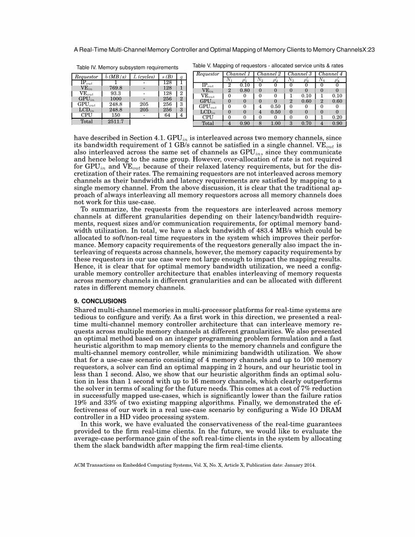
A Real-Time Multi-Channel Memory Controller and Optimal Mapping of Memory Clients to Memory ChannelsX:23
Table IV. Memory subsystem requirements
Requestor b (MB/s) L (cycles) s (B) gIPout 1 - 128 1VEin 769.8 - 128 1VEout 93.3 - 128 2GPUin 1000 - 256 2GPUout 248.8 205 256 3LCDin 248.8 205 256 3CPU 150 - 64 4Total 2511.7
Table V. Mapping of requestors - allocated service units & rates
Requestor Channel 1 Channel 2 Channel 3 Channel 4N1 ρ′1 N2 ρ′2 N3 ρ′3 N4 ρ′4
IPout 2 0.10 0 0 0 0 0 0VEin 2 0.80 0 0 0 0 0 0VEout 0 0 0 0 1 0.10 1 0.10GPUin 0 0 0 0 2 0.60 2 0.60GPUout 0 0 4 0.50 0 0 0 0LCDin 0 0 4 0.50 0 0 0 0CPU 0 0 0 0 0 0 1 0.20Total 4 0.90 8 1.00 3 0.70 4 0.90
have described in Section 4.1. GPUin is interleaved across two memory channels, sinceits bandwidth requirement of 1 GB/s cannot be satisfied in a single channel. VEout isalso interleaved across the same set of channels as GPUin, since they communicateand hence belong to the same group. However, over-allocation of rate is not requiredfor GPUin and VEout because of their relaxed latency requirements, but for the dis-cretization of their rates. The remaining requestors are not interleaved across memorychannels as their bandwidth and latency requirements are satisfied by mapping to asingle memory channel. From the above discussion, it is clear that the traditional ap-proach of always interleaving all memory requestors across all memory channels doesnot work for this use-case.To summarize, the requests from the requestors are interleaved across memory
channels at different granularities depending on their latency/bandwidth require-ments, request sizes and/or communication requirements, for optimal memory band-width utilization. In total, we have a slack bandwidth of 483.4 MB/s which could beallocated to soft/non-real time requestors in the system which improves their perfor-mance. Memory capacity requirements of the requestors generally also impact the in-terleaving of requests across channels, however, the memory capacity requirements bythese requestors in our use case were not large enough to impact the mapping results.Hence, it is clear that for optimal memory bandwidth utilization, we need a config-urable memory controller architecture that enables interleaving of memory requestsacross memory channels in different granularities and can be allocated with differentrates in different memory channels.
9. CONCLUSIONS
Sharedmulti-channel memories in multi-processor platforms for real-time systems aretedious to configure and verify. As a first work in this direction, we presented a real-time multi-channel memory controller architecture that can interleave memory re-quests across multiple memory channels at different granularities. We also presentedan optimal method based on an integer programming problem formulation and a fastheuristic algorithm to map memory clients to the memory channels and configure themulti-channel memory controller, while minimizing bandwidth utilization. We showthat for a use-case scenario consisting of 4 memory channels and up to 100 memoryrequestors, a solver can find an optimal mapping in 2 hours, and our heuristic tool inless than 1 second. Also, we show that our heuristic algorithm finds an optimal solu-tion in less than 1 second with up to 16 memory channels, which clearly outperformsthe solver in terms of scaling for the future needs. This comes at a cost of 7% reductionin successfully mapped use-cases, which is significantly lower than the failure ratios19% and 33% of two existing mapping algorithms. Finally, we demonstrated the ef-fectiveness of our work in a real use-case scenario by configuring a Wide IO DRAMcontroller in a HD video processing system.In this work, we have evaluated the conservativeness of the real-time guarantees
provided to the firm real-time clients. In the future, we would like to evaluate theaverage-case performance gain of the soft real-time clients in the system by allocatingthem the slack bandwidth after mapping the firm real-time clients.
ACM Transactions on Embedded Computing Systems, Vol. X, No. X, Article X, Publication date: January 2014.

X:24 M.D.Gomony et al.
REFERENCES
E. Aho, J. Nikara, P.A. Tuominen, and K. Kuusilinna. 2009. A case for multi-channel memories in videorecording. In Design, Automation Test in Europe Conference Exhibition (DATE), 2009. 934–939.
B. Akesson and K. Goossens. 2011a. Architectures and modeling of predictable memory controllers for im-proved system integration. In Design, Automation Test in Europe Conference Exhibition (DATE), 2011.1–6.
B. Akesson and K. Goossens. 2011b.Memory Controllers for Real-Time Embedded Systems (first edition ed.).Springer.
B. Akesson, L. Steffens, E. Strooisma, and K. Goossens. 2008. Real-Time Scheduling Using Credit-Controlled Static-Priority Arbitration. In Embedded and Real-Time Computing Systems and Applica-tions (RTCSA), 2008. 14th IEEE International Conference on. 3–14.
M. Awasthi, D.W. Nellans, K. Sudan, R. Balasubramonian, and A. Davis. 2010. Handling the problems andopportunities posed by multiple on-chip memory controllers. In Proceedings of the 19th internationalconference on Parallel architectures and compilation techniques (PACT ’10). ACM, 319–330.
S. Bayliss and G.A. Constantinides. 2012. Analytical synthesis of bandwidth-efficient SDRAM address gen-erators. Microprocess. Microsyst. 36, 8 (Nov. 2012), 665–675.
A.C. Bonatto, A.B. Soares, and A.A. Susin. 2011. Multichannel SDRAM controller design for H.264/AVCvideo decoder. In Programmable Logic (SPL), 2011 VII Southern Conference on. 137–142.
C. Bouquet. 2000. Optimal Multi-channel Memory Controller System. Patent number: 6643746. (2000).
F. Cabarcas, A. Rico, Y. Etsion, and A. Ramirez. 2010. Interleaving granularity on high bandwidth memoryarchitecture for CMPs. In Embedded Computer Systems (SAMOS), International Conference on. 250–257.
P. Casini. 2008. SoC Architecture to Multichannel Memory Management Using Sonics IMT. White paper.(2008). Sonics, inc.
CPLEX. IBM ILOG CPLEX Optimizer. http://www.ibm.com.
R.L. Cruz. 1991. A calculus for network delay. II. Network analysis. Information Theory, IEEE Transactionson 37, 1 (1991), 132–141.
M.D. Gomony, B. Akesson, and K. Goossens. 2013. Architecture and optimal configuration of a real-timemulti-channel memory controller. In Design, Automation Test in Europe Conference Exhibition (DATE),2013. 1307–1312.
M.D. Gomony, C. Weis, B. Akesson, N. Wehn, and K. Goossens. 2012. DRAM selection and configuration forreal-time mobile systems. In Design, Automation Test in Europe Conference Exhibition (DATE). 51–56.
S. Goossens, J. Kuijsten, B. Akesson, and K. Goossens. 2013. A Reconfigurable Real-Time SDRAMControllerfor Mixed Time-Criticality Systems. In Int’l Conference on Hardware/Software Codesign and SystemSynthesis (CODES+ISSS), 2013.
HMC. http://www.hybridmemorycube.org.
H. Hongqi, X. Jiadong, D. Zhemin, and S. Jingnan. 2007. High Efficiency Synchronous DRAM Controller forH.264 HDTV Encoder. In Signal Processing Systems, 2007 IEEE Workshop on. 373–376.
JEDEC. Wide I/O Single Data Rate Specification. http://www.jedec.org.
M. Katevenis, S. Sidiropoulos, and C. Courcoubetis. 1991. Weighted round-robin cell multiplexing in ageneral-purpose ATM switch chip. Selected Areas in Communications, IEEE Journal on 9, 8 (1991),1265–1279.
H. Kim, D. de Niz, B. Andersson, M. Klein, O. Mutlu, and R. Rajkumar. 2014. Bounding memory interferencedelay in COTS-based multicore systems. In IEEE Real-Time Technology and Applications Symposium(RTAS 14).
P. Kollig, C. Osborne, and T. Henriksson. 2009. Heterogeneous multi-core platform for consumer multimediaapplications. In Proceedings of the Conference on Design, Automation and Test in Europe (DATE ’09).European Design and Automation Association, 1254–1259.
C. Lee, M. Potkonjak, and W.H. Mangione-Smith. 1997. MediaBench: a tool for evaluating and synthesizingmultimedia and communications systems. In Microarchitecture, 1997. Proceedings., Thirtieth AnnualIEEE/ACM International Symposium on. 330–335.
Y. Li, B. Akesson, and K. Goossens. 2014. Dynamic Command Scheduling for Real-TimeMemory Controllers.In Proc. Euromicro Conference on Real-Time Systems (ECRTS).
C. Lin and S.A. Brandt. 2005. Improving Soft Real-Time Performance Through Better Slack Management.In Real-Time Systems Symposium, 2005. RTSS 2005. 26th IEEE International. 12 pp.–421.
I. Loi and L. Benini. 2010. An efficient distributed memory interface for many-core platform with 3D stackedDRAM. In Design, Automation Test in Europe Conference Exhibition (DATE), 2010. 99–104.
D. Melpignano, L. Benini, E. Flamand, B. Jego, T. Lepley, G. Haugou, F. Clermidy, and D. Dutoit. 2012.Platform 2012, a many-core computing accelerator for embedded SoCs: performance evaluation of visual
ACM Transactions on Embedded Computing Systems, Vol. X, No. X, Article X, Publication date: January 2014.

A Real-Time Multi-Channel Memory Controller and Optimal Mapping of Memory Clients to Memory ChannelsX:25
analytics applications. In Proceedings of the 49th Annual Design Automation Conference (DAC ’12).ACM, 1137–1142.
J. Nikara, E. Aho, P.A. Tuominen, and K. Kuusilinna. 2009. Performance analysis of multi-channelmemoriesin mobile devices. In System-on-Chip (SOC), 2009. International Symposium on. 128–131.
Y. Ou, N. Xiao, and M. Lai. 2011. A Scalable Multi-channel Parallel NAND Flash Memory Controller Archi-tecture. In Chinagrid Conference (ChinaGrid), 2011 Sixth Annual. 48–53.
M. Paolieri, E. Quinones, and F. J. Cazorla. 2013. Timing Effects of DDR Memory Systems in Hard Real-time Multicore Architectures: Issues and Solutions. ACM Trans. Embed. Comput. Syst. 12, 1s, Article64 (March 2013), 26 pages.
J. Reineke, I. Liu, H. D. Patel, S. Kim, and E. A. Lee. 2011. PRET DRAM controller: bank privatizationfor predictability and temporal isolation. In Proceedings of the seventh IEEE/ACM/IFIP internationalconference on Hardware/software codesign and system synthesis (CODES+ISSS ’11). ACM, 99–108.
J.C. Sancho, M. Lang, and D.K. Kerbyson. 2010. Analyzing the trade-off between multiple memory con-trollers and memory channels on multi-core processor performance. In Parallel Distributed Processing,Workshops and Phd Forum (IPDPSW), 2010 IEEE International Symposium on. 1–7.
H. Shah, A. Raabe, and A. Knoll. 2012. Bounding WCET of applications using SDRAM with Priority BasedBudget Scheduling in MPSoCs. In Design, Automation Test in Europe Conference Exhibition (DATE),2012. 665–670.
M. Shreedhar and G. Varghese. 1996. Efficient fair queuing using deficit round-robin. Networking,IEEE/ACM Transactions on 4, 3 (1996), 375–385.
SimpleScalar. http://www.simplescalar.com.
S. Sriram and S. S. Bhattacharyya. 2000. Embedded Multiprocessors: Scheduling and Synchronization (1sted.). Marcel Dekker, Inc., New York, NY, USA.
L. Steffens, M. Agarwal, and P. Wolf. 2008. Real-Time Analysis for Memory Access in Media Processing SoCs:A Practical Approach. In Real-Time Systems, 2008. ECRTS ’08. Euromicro Conference on. 255–265.
M. Steine, M. Bekooij, and M. Wiggers. 2009. A Priority-Based Budget Scheduler with ConservativeDataflow Model. In Digital System Design, Architectures, Methods and Tools, 2009. DSD ’09. 12th Eu-romicro Conference on. 37–44.
A. Stevens. 2010. QoS for High-Performance and Power-Efficient HD Multimedia. ARM White paper,http://wwww.arm.com. (2010).
D. Stiliadis and A. Varma. 1998. Latency-rate servers: a general model for analysis of traffic schedulingalgorithms. Networking, IEEE/ACM Transactions on 6, 5 (1998), 611–624.
Texas Instruments Inc. TMS320VC5505/5504 DSP Direct Memory Access (DMA) Controller.http://www.ti.com.
C. H. (Kees) van Berkel. 2009. Multi-core for mobile phones. In Proceedings of the Conference on Design,Automation and Test in Europe (DATE ’09). 1260–1265.
P. van der Wolf and J. Geuzebroek. 2011. SoC infrastructures for predictable system integration. In Design,Automation Test in Europe Conference Exhibition (DATE), 2011. 1–6.
Z.P. Wu, Y. Krish, and R. Pellizzoni. 2013. Worst Case Analysis of DRAM Latency in Multi-requestor Sys-tems. In Real-Time Systems Symposium (RTSS), 2013 IEEE 34th. 372–383.
Xilinx Inc. LogiCORE IP XPS Multi-channel External Memory Controller (XPS MCH EMC).http://www.xilinx.com.
G. Zhang, H. Wang, X. Chen, S. Huang, and P. Li. 2012. Heterogeneous multi-channel: Fine-grained DRAMcontrol for both system performance and power efficiency. InDesign Automation Conference (DAC), 201249th ACM/EDAC/IEEE. 876–881.
T. Zhang, K. Wang, Y. Feng, Y. Chen, Q. Li, B. Shao, J. Xie, X. Song, L. Duan, Y. Xie, X. Cheng, and Y. Lin.2010. A 3D SoC design for H.264 application with on-chip DRAM stacking. In 3D Systems IntegrationConference (3DIC), 2010 IEEE International. 1–6.
Z. Zhu, Z. Zhang, and X. Zhang. 2002. Fine-grain priority scheduling on multi-channel memory systems.In High-Performance Computer Architecture, 2002. Proceedings. Eighth International Symposium on.107–116.
Received month year; revised month year; accepted month year
ACM Transactions on Embedded Computing Systems, Vol. X, No. X, Article X, Publication date: January 2014.